

Hellwig 7825 User Manual
559-734-7451 800-367-5480 FAX 559-734-7460
INSTALLATION INSTRUCTIONS
Rear Stabilizer Bar
S-10, S-15 Pickups
Thank you for purchasing a quality Hellwig Product.
PLEASE READ THIS INSTRUCTION SHEET COMPLETELY BEFORE STARTING YOUR INSTALLATION
1 2
TORQUE TABLE
BOLT SIZE: 3/8” = 20-30 ft. lbs. – 7/16” = 35-45 ft. lbs. – ½” = 50-70 ft. lbs. – 9/16” = 70-90 ft. lbs.
SAFETY: BEFORE STARTING YOUR INSTALLATION, BE SURE TO SET PARKING BRAKE AND CHOCK TIRES.
NOTE: TO EASE INSTALLATION AND TO PROPERLY ADJUST BAR, THE WEIGHT OF THE VEHICLE MUST BE
ON THE SUSPENSION, AS IF DRIVING DOWN THE ROAD. DO NOT RAISE VEHICLE BY FRAME.
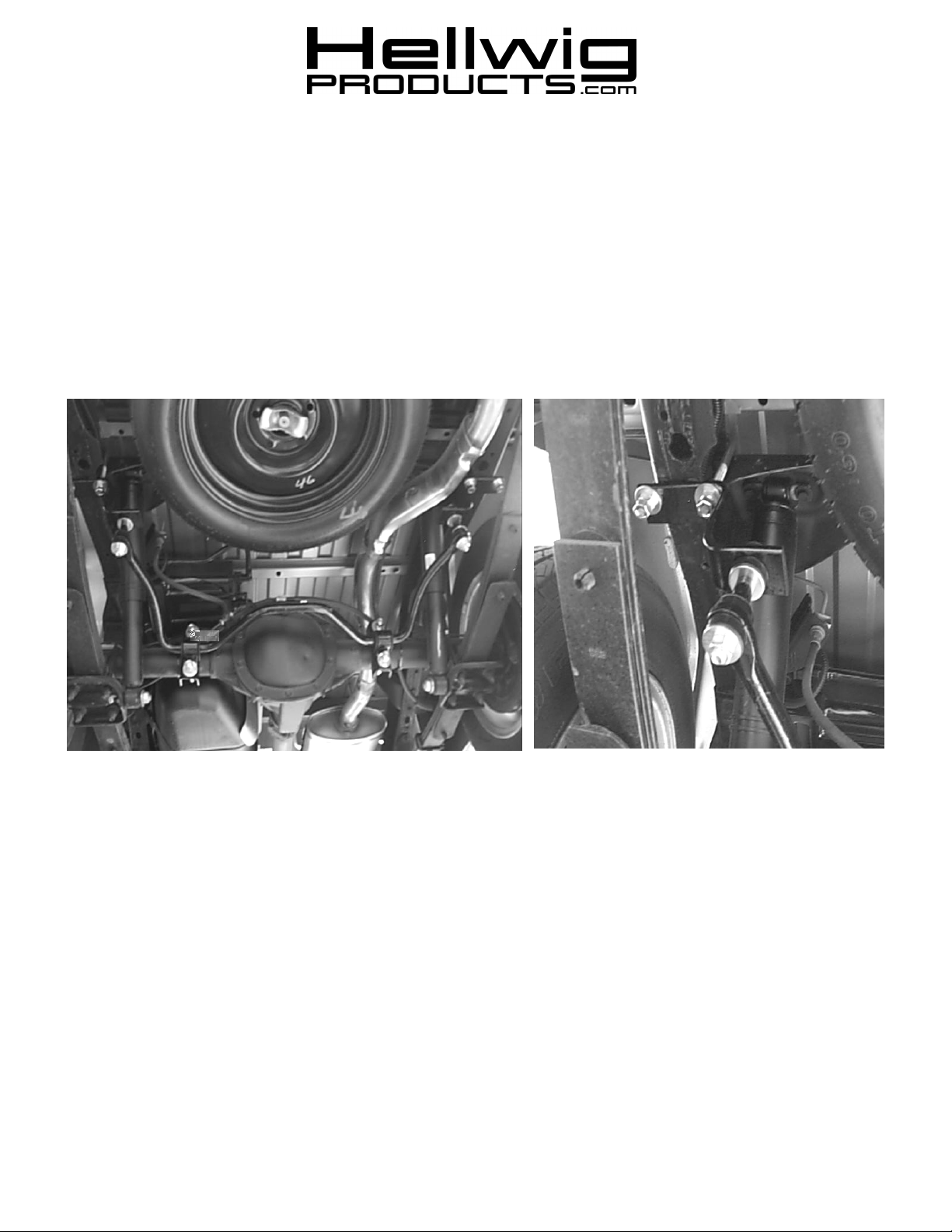
1. As shown in picture 2, locate the square U-bolts over the top of the frame rail directly behind the shock brackets. Be sure to
put U-bolts under any brake lines, wires, cables, or hoses to avoid possible damage. Install hanger brackets with slotted
holes toward rear of vehicle. There are left (driver’s side) and right (passenger side) versions of the hanger brackets so care
must be taken to install the brackets on the correct side of the vehicle. When oriented correctly, the brackets will install as
shown in picture 2.
2. Install flat washers and nuts on the U-bolts. LEAVE LOOSE AT THIS TIME.
(R-376) 08/07/03
2
559-734-7451 800-367-5480 FAX 559-734-7460
3
4
3. Place the D-shaped poly bushings onto straight areas of the bar on each side of the center hump as shown in picture 3. Place
the U-plates over the D-bushings.
4. Hold the bar up to the axle and locate the position on the axles to mount to U-bolts. Install the U-bolt that best fits the axle
tube. Be sure to put the U-bolts under any brake lines, wires, or hoses on the axle to avoid possible damage. The threads of
the U-bolts will point rearward.
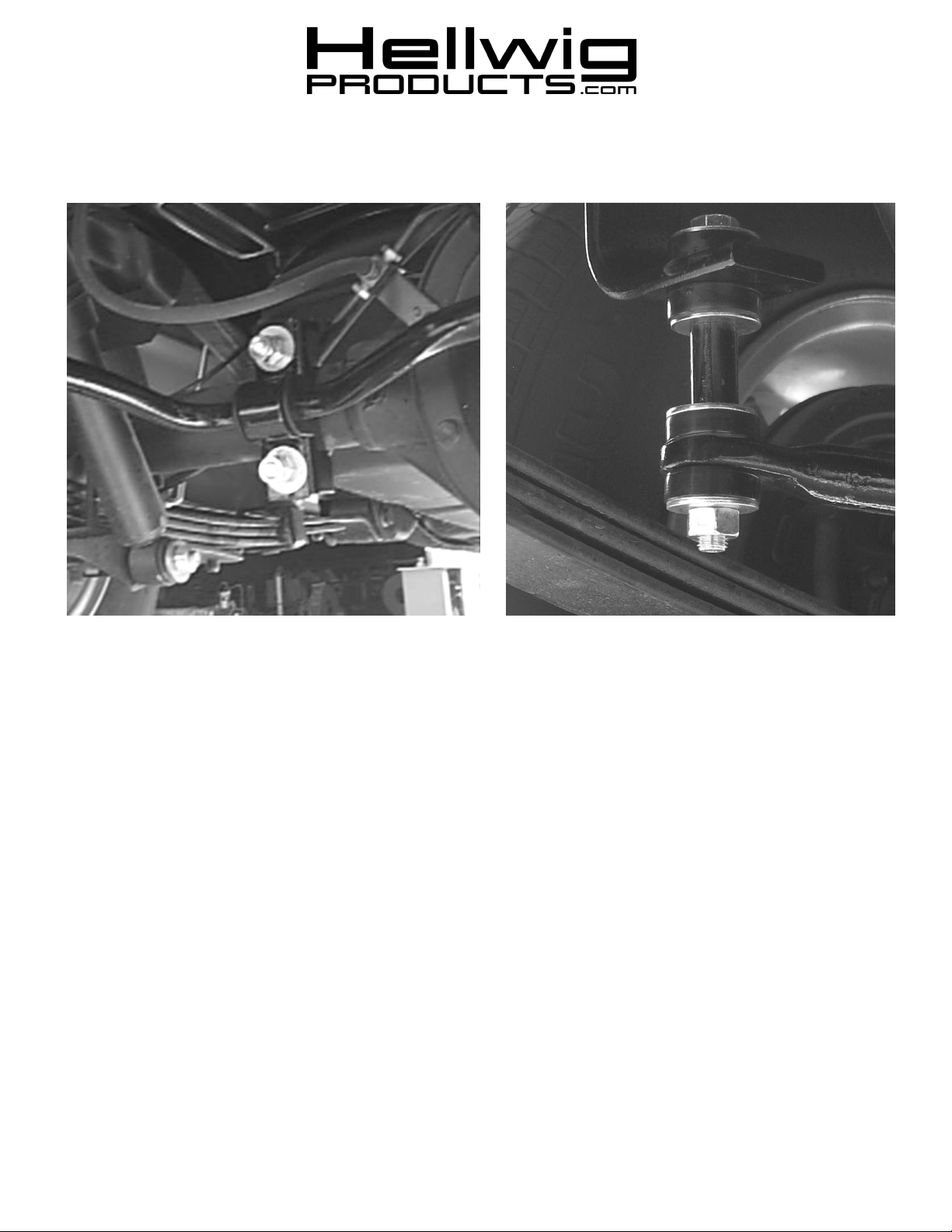
5. Place the saddle brackets over the legs of the U-bolts on the axles. Attach bar to axle by inserting legs of U-bolts through
holes in the U-plates and fasten with flat washers and nuts provided. LEAVE LOOSE AT THIS TIME FOR
ADJUSTMENT LATER.
6. Install end link hardware as shown in picture number 4 using the 7/16” X4 1/2” bolt and the bushing kit to connect the frame
bracket to the sway bar. Align end links so that they are perpendicular to the sway bar and tighten nut until the bushings
bulge slightly.
7. Align the sway bar side to side so that it is centered. The U-bolts and saddle brackets can be rotated on the axle up and down
so that the arms of the sway bar are parallel with the ground. Adjust hanger brackets so that the end links are aligned as
shown in picture 4. Torque the hanger bracket U-bolts to 35 ft-lb and the axle U-bolts to 45 ft-lb. Add a second nut to the
U-bolts and tighten against the first to lock both nuts in place.
8. Bounce the vehicle checking for clearance on all undercarriage components i.e.: exhaust, shocks, etc. Recheck installation
after 100 miles and periodically thereafter.
ATTENTION INSTALLER: PLEASE MAKE SURE CUSTOMER RECEIVES THIS INSTRUCTION SHEET, ALL IMPORTANT NOTE CARDS, WARNING CARDS AND THE WARRANTY FORM.
(R-376) 08/07/03
 Loading...