

Hellwig 7676 User Manual
559-734-7451 800-367-5480 FAX 559-734-7460
INSTALLA TION INSTRUCTIONS
FRONT STABILIZER BAR
2005+ F-250/350 Front Sway Bar
Thank you for purchasing a quality Hellwig Product.
2 1
TORQUE TABLE
BOLT SIZE: 3/8” = 20-30 ft. lbs. – 7/16” = 35-45 ft. lbs. – ½” = 50-70 ft. lbs. – 9/16” = 70-90 ft. lbs.
SAFETY: BEFORE STARTING YOUR INSTALLATION, BE SURE TO SET PARKING BRAKE AND CHOCK TIRES.
NOTE: TO EASE INSTALLATION AND TO PROPERLY ADJUST BAR, THE WEIGHT OF THE VEHICLE MUST BE ON THE SUSPEN-
SION, AS IF DRIVING DOWN THE ROAD. DO NOT RAISE VEHICLE BY FRAME.
NOTE: THIS ANTI SWAY BAR IS DESIGNED TO REPLACE THE FACTORY MOUNTED SWAY BAR USING THE FACTORY END
LINKS AND MOUNTING HARDWARE FOR THE U-PLATES AND THE FACTORY END LINKS.
1. Remove the factory installed sway bar and all the mounting hardware. Do not discard the end link assemblies and the U-plate
mounting bolts as they will be used for reinstallation of the new front sway bar.
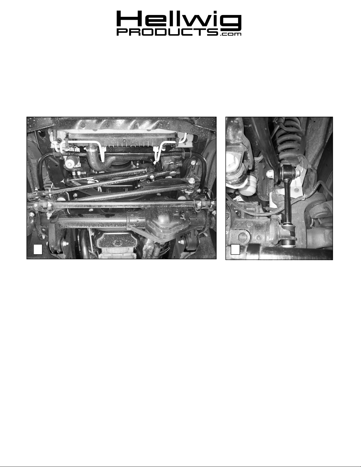
2. Install the D-shaped poly bushings on the sway bar in the same location as the factory sway bar. Position the sway bar up on
the vehicles frame using the U-plates provided. Fasten with the mounting bolts that were removed in step (1). Leave loose at
this time to allow for adjustment later. .
3. With the sway bar properly aligned and the end links are aligned properly, torque all the mounting hardware to the factory
specifications. SEE PHOTO (1).
4. Test drive your vehicle and recheck your installation re-torque if necessary. Recheck your installation on a regular monthly
basis thereafter.
ATTENTION INSTALLER: BE SURE THAT THE CUSTOMER RECEIVES THIS INSTRUCTION SHEET, ALL
IMORTANT NOTE CARDS AND THE WARRANTY FORM
7676 ( R-7676 ) 08/11/05

559-734-7451 800-367-5480 FAX 559-734-7460
PARTS LIST
FSB # 7676
PART # QTY DESCRIPTION
20217676 1 1-1/8” SWAY BAR
20907676 1 COMPLETION KIT #-7676
20800069 2 U-PLATE
111000372 2 1 1/8” POLY D-BUSHING
135007676 1 INSTRUICTION SHEET #-7676
7676 ( R-7676 ) 08/11/05
 Loading...