


P.O. Box 90004
Bowling Green, KY 42102-9004
Hardwired
Electronic
Chime
© 2007 HeathCo LLC |
598-1313-00 |
Chime Replacement Installation
IMPORTANT: Proper installation requires a diode on the front door push button. See Diode Installation Instructions (page 5) after completing steps 1 through 13 below.
Note: Electrical work must be in accordance with national and local electrical codes. If in doubt, consult a qualified electrician.
1.Verify transformer power rating. Power must be supplied from a 16 Volt AC, 10 Watt or a 16 Volt AC, 15 Watt transformer (Heath®/Zenith models 122C, 121AC, or 125C).
2.Remove cover from existing chime.
3.Label all wires before disconnecting. Using masking tape, mark each wire according to existing chime terminal markings.
•“F” – Front Push Button Wire
•“T” – Transformer Wire
•“R” – Rear Push Button Wire (Note: Some installations may not include rear door push button.)
4.Disconnect all wires from existing chime.
5.Remove existing chime base from wall.
6.Determine proper chime base orientation. The chime cover style will determine orientation.
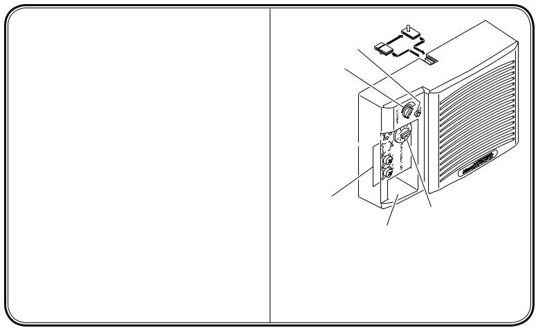
7.A cover pin is installed on two sides of the chime base. After determining correct orientation, remove, turn over, and reinstall the cover pin located on top of chime base (see Figure 1).
Continued
- - |
598-1313-00 |
 Cover Pin
Test Button
Volume Control
Base Orientation 

Marking
Transformer and
Push Button Wire
Connections
Wire Entrance Hole
Front Door Tune Selection Switch (3 Selections or 10 Selections
– Depending on Model)
Figure 1 - Electronic Chime Identification
(2300 Base Shown)
Illustrations may vary from actual chime unit.
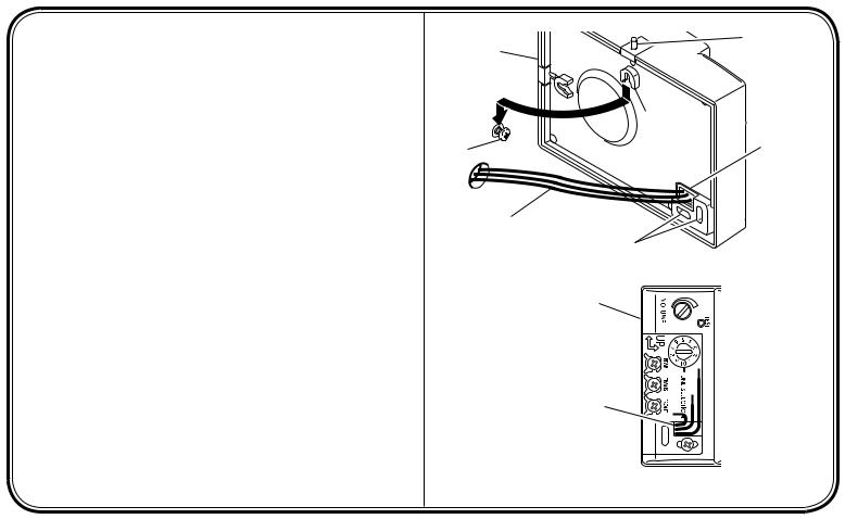
8.Determine mounting location. Note: The back of the chime base is recessed to allow the base to cover the wire hole in the wall when mounting the base to the wall.
9.Mountchimebasetowallusingscrewsandanchorsprovided(see Figure 2). (Drill 7/32" diameter pilot hole for wall anchors.)
•Mount keyhole screw to wall leaving about 1/8" (3 mm) of the screw threads exposed. Note: Keyhole slot is located about 3/4" (19 mm) from top of chime.
•Route wires through wire entrance hole in new chime base.
•Using keyhole on back of chime base, hang base on screw.
•Level chime base.
•Using the slots located in the bottom of the wire entrance hole, insert second screw through whichever slot is horizontal and attach to wall and tighten.
Continued
Back of |
Cover Pin |
|
Chime Base |
Installed |
|
|
Correctly |
|
|
Keyhole Slot |
|
Keyhole |
Wire |
|
Screw |
||
Entrance |
||
|
||
|
Hole |
|
Existing Chime |
Mounting |
|
Wires from Wall |
||
|
Screw Slots |
|
|
Front of Chime |
|
|
Base |
Wire Entrance Hole
Mounting Screw 
Figure 2 - Mounting Chime Base to Wall
- - |
598-1313-00 |
- - |
598-1313-00 |
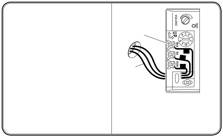
10.Connect wire “F” to screw terminal marked “FRONT”. Connect wire “T” to screw terminal marked “TRANS”. Connect wire “R” to screw terminal marked “REAR” (See Figure 3). Note: Some installations may not include rear door push button.
11.Connect diode to front push button (see page 5).
12.Press the “TEST” button to verify the transformer is connected properly and to listen to the selected front door tune.
13.Hang cover on cover pin.
Note: Never use cleaners or polishes. Never use any fluids on the electronic chime mechanism. Use dry cloth to clean chime cover and base.
Tune Selection (Front Door)
To Select a Tune to Play Each Time the Push Button is Pressed:
1.Turn or slide the tune selection switch (depending upon model) to select a tune.
2.Press the “TEST” button to hear the selected tune.
3.Adjust the “VOLUME” knob to the desired volume level.
Rear Door Push Button
(if Applicable)
R

 T
T
Existing Chime |
F |
|
|
Wires from Wall |
|
Replacement
Chime Base
Figure 3 - Electronic Chime Wiring
(2300 Base Shown)
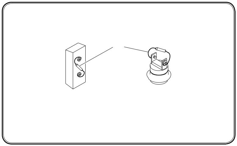
DIODE INSTALLATION INSTRUCTIONS
A small electrical component called a “diode” is required for this chime to play the entire tune. This diode must be installed on the terminal screws of the front door push button (see Figure 4). If not already installed on push button, attach supplied diode as shown below. If, with the diode in place, the chime does not play the complete melody, see Troubleshooting, page 6.
Diode
 Front Door Push Button
(Styles May Vary)
Figure 4 - Attaching Diode to Front Door Push Button
- - |
598-1313-00 |

- - |
598-1313-00 |
TROUBLESHOOTING
Chime does not sound:
•Check Chime: Disconnect wire from terminal marked “TRANS”. Have someone operate push button at front door while you momentarily touch the “TRANS” wire to terminal marked “FRONT”. You will see a small spark if push button, wiring, and transformer are operating properly. Repeat the steps for “REAR” terminal and rear push button. If wiring between transformer and push button(s) check out properly, replace chime.
•Check Transformer: Test transformer voltage output with a volt meter. If a volt meter is not available, momentarily touch the two low-voltage terminals with a screwdriver. You will see a small spark if transformer is operating properly. If no spark is evident, replace transformer.
•Check Push Button(s): Remove suspected push button from door frame, disconnect wire from terminals and touch bare wires together. If chime operates, push button is defective. Replace push button.
Chime sounds but does not complete entire tune:
•Check Diode on Front Push Button:Verify diode is attached securely to push button (see page 5). Chime may not function properly if a diode is installed on more than one push button. Note: Some push buttons have pre-installed diodes. An additional diode should not be added if the push button has a pre-installed diode. If chime still does not play entire tune, replace diode (Type 1N4003-200V-1A, available at local electrical component supplier).

Technical Service
Please call 1-800-858-8501 (English speaking only) for assistance before returning product to store.
If you experience a problem, follow this guide. You may also want to visit our Web site at: www.hzsupport.com. If the problem persists, call* for assistance at 1-800-858-8501, 7:30 AM to 4:30 PM CST (M-F). You may also write* to:
HeathCo LLC
P.O. Box 90004, Bowling Green, KY 42102-9004 ATTN: Technical Service Specialty Products
* If contacting Technical Service, please have the following information available: Model Number, Date of Purchase, and Place of Purchase.
No Service Parts Available for this Product
ONE YEAR LIMITED WARRANTY
This is a “Limited Warranty” which gives you specific legal rights. You may also have other rights which vary from state to state or province to province.
For a period of one year from the date of purchase, any malfunction caused by factory defective parts or workmanship will be corrected at no charge to you. Not Covered - Repair service, adjustment and calibration due to misuse, abuse or negligence, light bulbs, batteries, and other expendable items are not covered by this warranty. Unauthorized service or modification of the product or of any furnished component will void this warranty in its entirety. This warranty does not include reimbursement for inconvenience, installation, setup time, loss of use, unauthorized service, or return shipping charges.
This warranty covers only HeathCo LLC assembled products and is not extended to other equipment and components that a customer uses in conjunction with our products.
THIS WARRANTY IS EXPRESSLY IN LIEU OF ALL OTHER WARRANTIES, EXPRESS OR IMPLIED, INCLUDING ANY WARRANTY, REPRESENTATION OR CONDITION OF MERCHANT ABILITY OR THAT THE PRODUCTS ARE FIT FOR ANY PARTICULAR PURPOSE OR USE, AND SPECIFICALLY IN
LIEU OF ALL SPECIAL, INDIRECT, INCIDENTAL, OR CONSEQUENTIAL DAMAGES.
REPAIR OR REPLACEMENT SHALL BE THE SOLE REMEDY OF THE CUSTOMER AND THERE SHALL BE NO LIABILITY ON THE PART OF HeathCo
LLC FOR ANY SPECIAL, INDIRECT, INCIDENTAL, OR CONSEQUENTIAL DAMAGES, INCLUDING BUT NOT LIMITED TO ANY LOSS OF BUSINESS OR PROFITS, WHETHER OR NOT FORESEEABLE. Some states or provinces do not allow the exclusion or limitation of incidental or consequential damages, so the above limitation or exclusion may not apply to you. Please keep your dated sales receipt, it is required for all warranty requests.
HeathCo LLC reserves the right to discontinue and to change specifications at any time without notice without incurring any obligation to incorporate new features in previously sold products.
- - |
598-1313-00 |

- -
Rear Door
Push Button
(If Applicable)
R
Transformer
T |
F
Front Door
Push Button
With Diode
598-1313-00
Chime
Chime System Wiring Diagram
 Loading...