


HD-9260
All MetAl Motion SenSor
QuArtz light Control
Model HD-9260
© 2008 HeathCo LLC 598-1188-02

Contents
Introduction ................................................................................................... 3
Package Contents ......................................................................................4
Installation ..................................................................................................... 5
Wall Mount ................................................................................................ 5
Eave Mount ............................................................................................... 5
Crossbar Mounting Bracket ..................................................................... 6
Standard Wiring ....................................................................................... 6
Controlling Non-Motion Sensing Fixtures ..............................................7
Finish Mounting .......................................................................................8
Specications ............................................................................................ 8
Test and Adjustment ..................................................................................... 9
Expected Coverage .................................................................................10
Operation ..................................................................................................... 12
Troubleshooting Guide ............................................................................... 13
JourneyMan® Lifetime Warranty ............................................................... 14
-2-
598-1188-02

Introduction
Dear Consumer:
We would like to thank you for purchasing this JourneyMan
that you have purchased the most durable motion sensor available today. This JourneyMan® product will
give you a lifetime worth of operation. We are so confident with the durability of this product that we
are backing it with a Lifetime Warranty.
Enhanced Performance Features
®
product. We at HeathCo LLC feel
☞ Rugged gripping teeth and finger screw provide full three-dimension adjustment of sensor head.
☞ Five silicon rubber gaskets seal internal components and controls from severe environmental
conditions.
☞ Stainless steel screws to prevent rust and corrosion.
☞ Built in 1.25 Mega Watt surge protection.
☞ A.S.I.C. (Application Specific Integrated Circuit) design allows more reliable performance.
☞ Range Boost option to extend range for those hard to cover areas.
☞ Extremely wide angle coverage (up to 270°). Adjustable with built-in lens shields.
☞ Easy to control other lights with your JourneyMan
®
fixture (up to 1000 Watts total load).
☞ Expanded lens area receives more infrared light improving detection sensitivity.
☞ Pulse count technology reduces false sensing from wind and rain for professional reliability.
☞ Automatic photocell deactivates unit in daylight to save energy.
☞ Power outage reset. Turns light off automatically if turned on by power interruption or electrical storm.
☞ Selectable light timer to set the time lights stay on after motion has been detected.
☞ Range control allows adjustment of coverage range.
☞ Manual override to turn lights on/off at your convenience with existing indoor wall switch.
598-1188-02
-3-
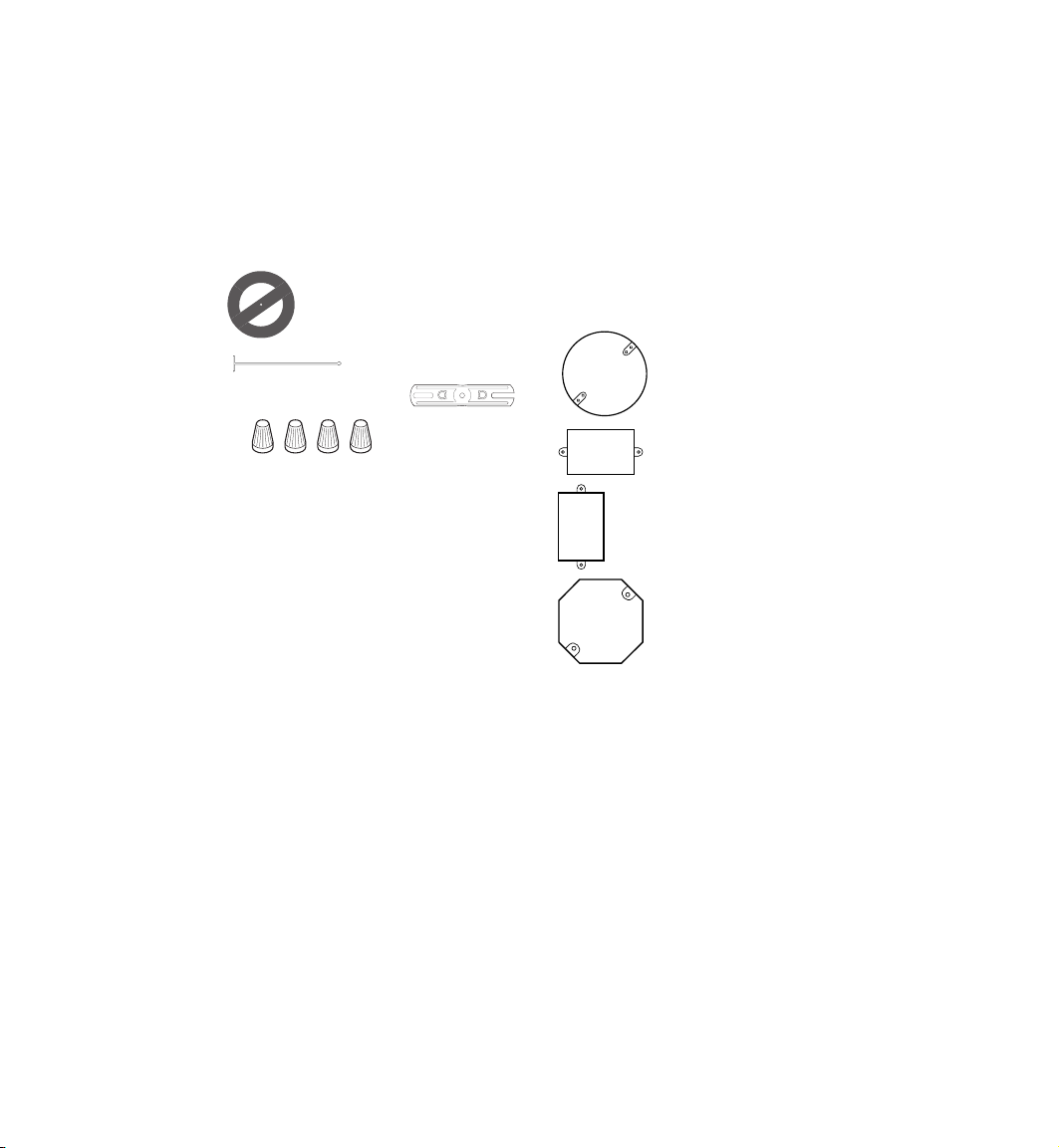
Package Contents
Additional Items Needed
• Motion Sensor Light Fixture
• Two 250 watt halogen lamps
• Manual
• Hardware Pack
1 Gasket
1 Hanger
1 Crossbar Mounting Bracket
4 Wire nuts
2 #6-32 X 3/4" screws
(for small rectangular boxes)
2 #8-32 X 3/8" screws
(for circular or octagon boxes)
2 #10-24 X 1/2" screws
(for water tight boxes)
1 M5 X 0.8 X 40 mm screw
(fixture to mounting bracket)
1 Rubber Plug
• Phillips screwdriver
• Ladder
Fits All Junction Box Configurations
Circular
Horizontal rectangular
Vertical rectangular
Octagon
-4-
598-1188-02
Installation
Caution: Before starting the installation, turn the power off at the
CirCuit Breaker.
If you want to use the Manual Override feature you will need to install the fixture on a circuit controlled
by a switch. The lamps are packed in boxes, inside the lampheads. Open the lampheads by removing
the screws at the top. Use a clean cloth or the foam packing around the lamps to keep your fingers off
the lamps. Install the lamps in the right side of the sockets first, then the left. Close the lampheads and
continue the installation as shown below.
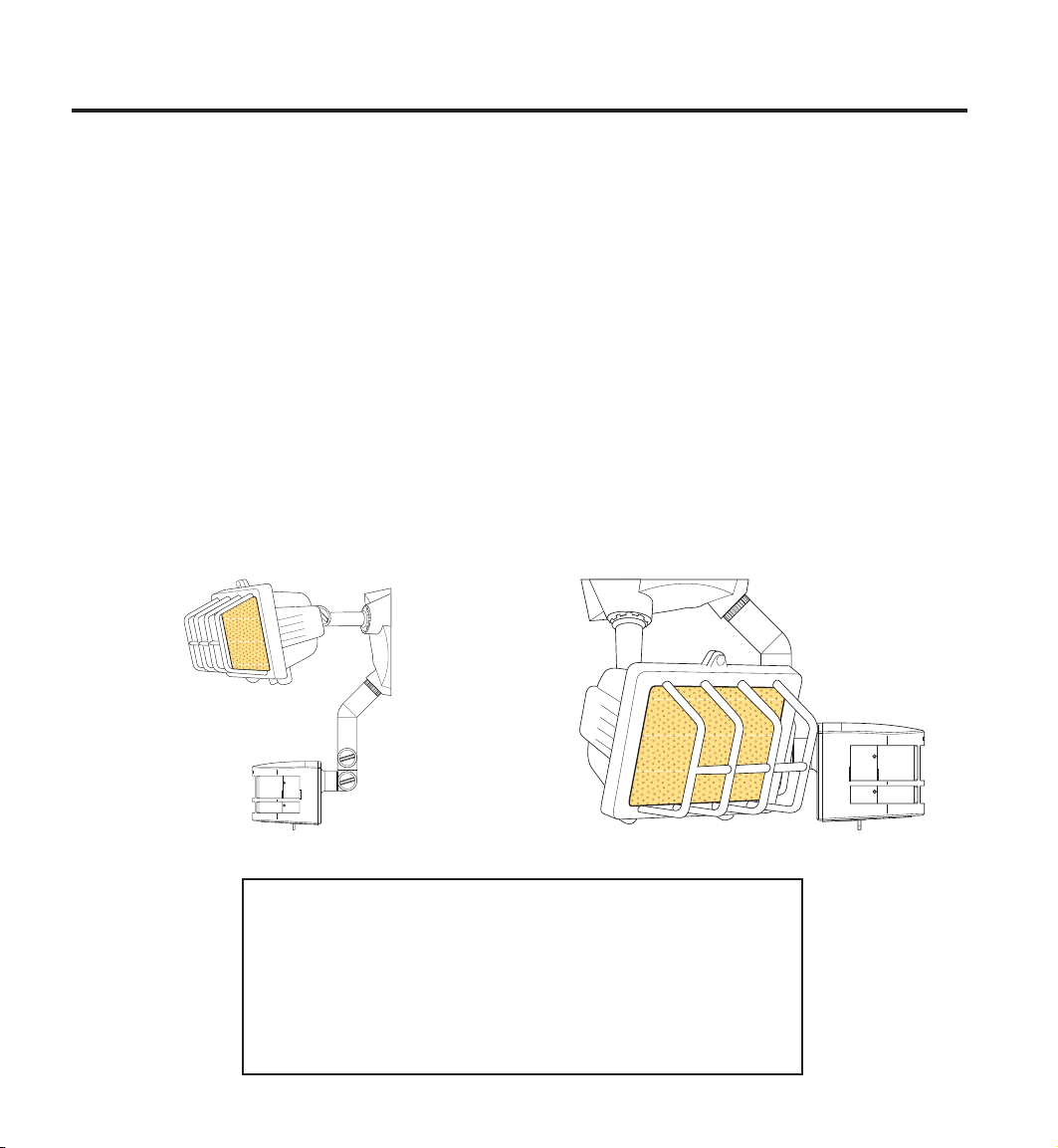
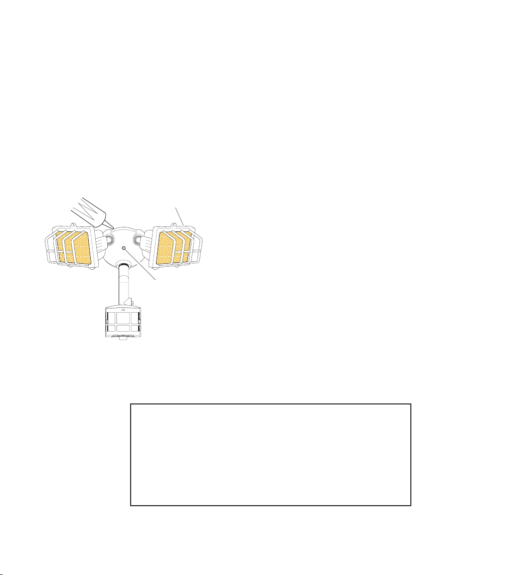
Wall Mount Eave Mount
❒ Loosen the thumbscrews holding the sensor
head and lampheads.
❒ Adjust the various parts so that the fixture
looks similar to this illustration.
❒ Finger tighten the thumbscrews at this time.
CAUTION: To Avoid Fire Or Burn Hazards:
• Allow fixture to cool before touching. The bulb and the fixture
operate at high temperatures.
• Keep fixture at least 3" (76 mm) from combustible materials.
Do not aim at objects closer than 3' (1 m).
• Use only type T 250W (max.) tungsten halogen 120 VAC
lamps.
598-1188-02
❒ Loosen the thumbscrews holding the sensor
head and lampheads.
❒ Adjust the various parts so that the fixture
looks similar to this illustration.
❒ Finger tighten the thumbscrews at this time.
-5-
Mount Fixture with Crossbar
Mounting Bracket
❒
Turn power off at the fuse or circuit breaker.
❒ Remove the existing light fixture (if appli-
cable).
❒ Install the mounting bracket as shown using
two screws supplied in hardware pack that fit
your junction box:
Rectangular Junction Box - Use two #6-32
x 3/4" screws.
Circular or Octagonal Junction Box - Use
two #8-32 x 3/8" screws.
Watertight Junction Box - Use two #10-24
x 1/2" screws.
❒ The plastic hanger can be used to hold the fix-
ture while wiring. The small end of the plastic
hanger can be threaded through the hole in the
center of the cover plate. The small end then
goes into one of the slots on the mounting
bracket.
❒ Route the light control’s wires through the
large gasket holes.
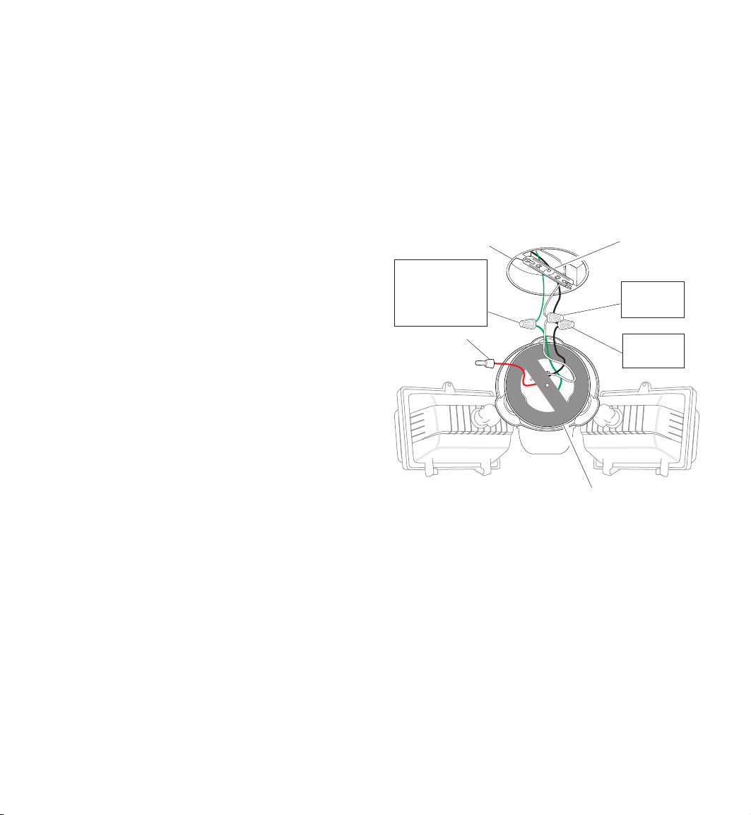
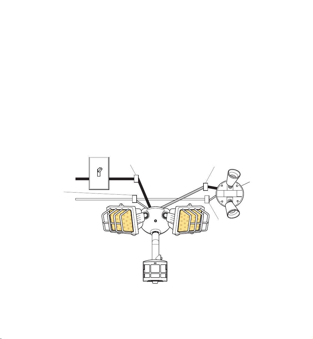
Standard Wiring
CAUTION: If you have not already turned the
power off at the breaker or fuse, do so now.
Connect the junction box wires to the fixture wires.
Twist together and secure with wire connectors.
CAUTION: If you are not controlling additional
fixtures from your JourneyMan® fixture, DO NOT
connect the RED wire or remove wire connector.
Junction Box
Green ground
wire to junc-
tion box
ground wire
RED, not
used in most
applications
Gasket
Mounting
Bracket
White to
White
Black to
Black
-6-
598-1188-02
Controlling Non-Motion Sensing Fixtures
❒ When wiring to additional standard fixture
only: Strip the motion sensor's red wire and
connect to the standard fixture's
Connect all white wires together. Total fixture
ratings must not exceed 1000 Watts (8.3 A).
NOTE: All wiring between fixtures should be run
in accordance with the National Electrical
Code (Canadian Electrical Code in Canada)
through conduit or another acceptable means.
Contact a qualified electrician if there is any
question as to the suitability of the system.
WHITE from Line
to WHITE from
JourneyMan
®
black wire.
BLACK from Switch to
BLACK from JourneyMan
❒ This fixture is provided with a sensor rated
for 1000 Watts. Since the fixture is only rated
500 Watts, 500 Watts of additional load may
be controlled by this sensor.
❒ When determining what a fixture is rated for,
do not simply look at the rating on the lamp in
the fixture. Look at the marking which speci
fies the maximum lamp wattage for which the
fixture is suitable.
❒
Once you have selected the fixtures to be connected and determined their maximum ratings,
add these ratings up. For instance, if you have 3
fixtures rated 100 Watts, 150 Watts, and 75 Watts
respectively, you have a total load of 325 Watts.
®
RED from JourneyMan® to
BLACK from Fixture
Standard
Fixture
-
598-1188-02
WHITE from Line to
WHITE from Fixture
Wiring to a Motion Light & Standard Fixture
-7-
Finish Mounting
Specifications
❒ Align the JourneyMan
®
cover plate, gasket,
and the mounting bracket hole. Secure with
M5 x 0.8 x 40 mm mounting screw supplied.
❒ Push the rubber plug firmly into place.
❒ If not installed on a weatherproof box, caulk
between the cover plate and mounting surface with silicone weather sealant.
To obtain maximum lamp
life, keep the tubular
lamps horizontal.
Rubber Plug
Range ..........................70 feet (21.0 m); 100
feet (30.5 m) with Range
Boost. Varies with sur-
rounding temperature.
Sensing Angle ............. Up to 270° (Adjustable)
Fixture Load ................Up to 500 Watts Maximum
Tungsten Incandescent
[Up to 250 Watts maxi
mum each lamp holder.]
Sensor Load Capacity . Up to 1000 Watts (8.3
amps), Maximum Tung
sten Incandescent
Power Requirements ... 120 VAC, 60 Hz
Operating Modes .........TEST, AUTO, and MAN
UAL OVERRIDE
Time Delay .................. 1, 5, 20 minutes
HeathCo LLC reserves the right to discontinue
products and to change specifications at any time
without incurring any obligation to incorporate
new features in products previously sold.
-
-
-
CAUTION: To Avoid Fire Or Burn Hazards:
• Allow fixture to cool before touching. The bulb and the fixture
operate at high temperatures.
• Keep fixture at least 3" (76 mm) from combustible materials.
Do not aim at objects closer than 3' (1 m).
• Use only type T 250W (max.) tungsten halogen 120 VAC
lamps.
-8-
598-1188-02
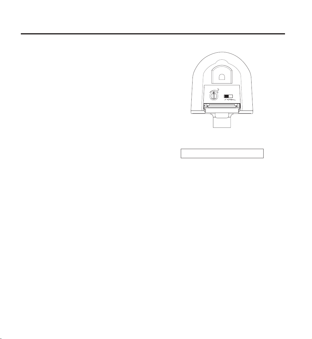
Test and Adjustment
B
O
O
S
T
MIN
TEST 1 5 20
RANGE
MAX
ON-TIME
NOTES: When first turned on or when switching
from Manual to Auto mode wait 1
1
/2
minutes for the unit to calibrate.
Testing with Range Boost on during day-
light may result in abnormal operation.
❒ Turn on the circuit breaker and light
switch.
❒ Open the control access cover (on bottom of unit)
by pulling down on the tab of the metal door.
❒
Turn the Range control to the center of its adjustment and the ON-TIME to TEST position.
Sensor Bottom
Do not aim the sensor at:
• Objects that change temperature rapidly, such
as heating vents and air conditioners, to help
avoid false triggering.
• Where
Nearby large, light-colored objects reflecting
•
pets or traffic may trigger the control.
light may trigger the shut-off feature. Do not
point other lights at the sensor.
598-1188-02
-9-
Adjustments Continued . . .
❒ Loosen the two thumb screws. Estimate the direction to aim the sensor
and tighten the thumbscrews just enough to hold the sensor in place.
NOTE: The top screw allows the sensor to rotate side to side. The bot
tom screw allows the sensor to rotate up and down.
❒ Walk through the coverage area noting where you are when the lights
turn on (also, the LED will flash several times when motion is detected).
Loosen the thumbscrews and readjust the sensor as necessary. Tighten
the thumbscrews (finger tight) when you are satisfied with the coverage
direction.
keep the controls facing downward.
❒ Adjust RANGE as needed to increase or decrease the range. Too much
sensitivity may cause false triggering in some environments.
❒ For maximum range, the sensor must be aiming straight out.
❒ Set the amount of TIME (1, 5, or 20 minutes) you want the lights to stay
on after motion is detected at night.
❒ Release the tab on metal door to allow door to close.
Keep the sensor at least 1 inch (25 mm) from lamps and
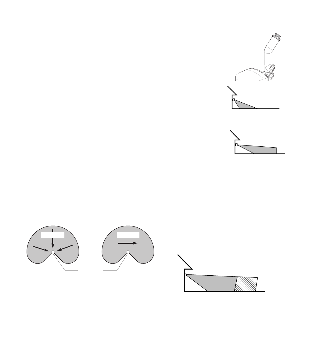
Expected Coverage
-
Aim Sensor Down
for Short Coverage
Aim Sensor Out for
Long Coverage
The sensor is less sensitive to motion directly
towards it, most sensitive to motion across its
field of view.
Motion Motion
Sensor
Least Sensitive Most Sensitive
When mounted 8 feet (2.4 m) from the ground, you
may expect the range shown below. If mounted
much higher the sensor may miss objects near the
ground. If mounted much lower the sensor range
may be reduced.
Maximum Range
(Sensor aiming straight out)
8 ft.
(2.4 m)
70 ft. (21.0 m) 100 ft. (30.5 m)
With RANGE With RANGE
Set to MAX Boosted
-10-
598-1188-02
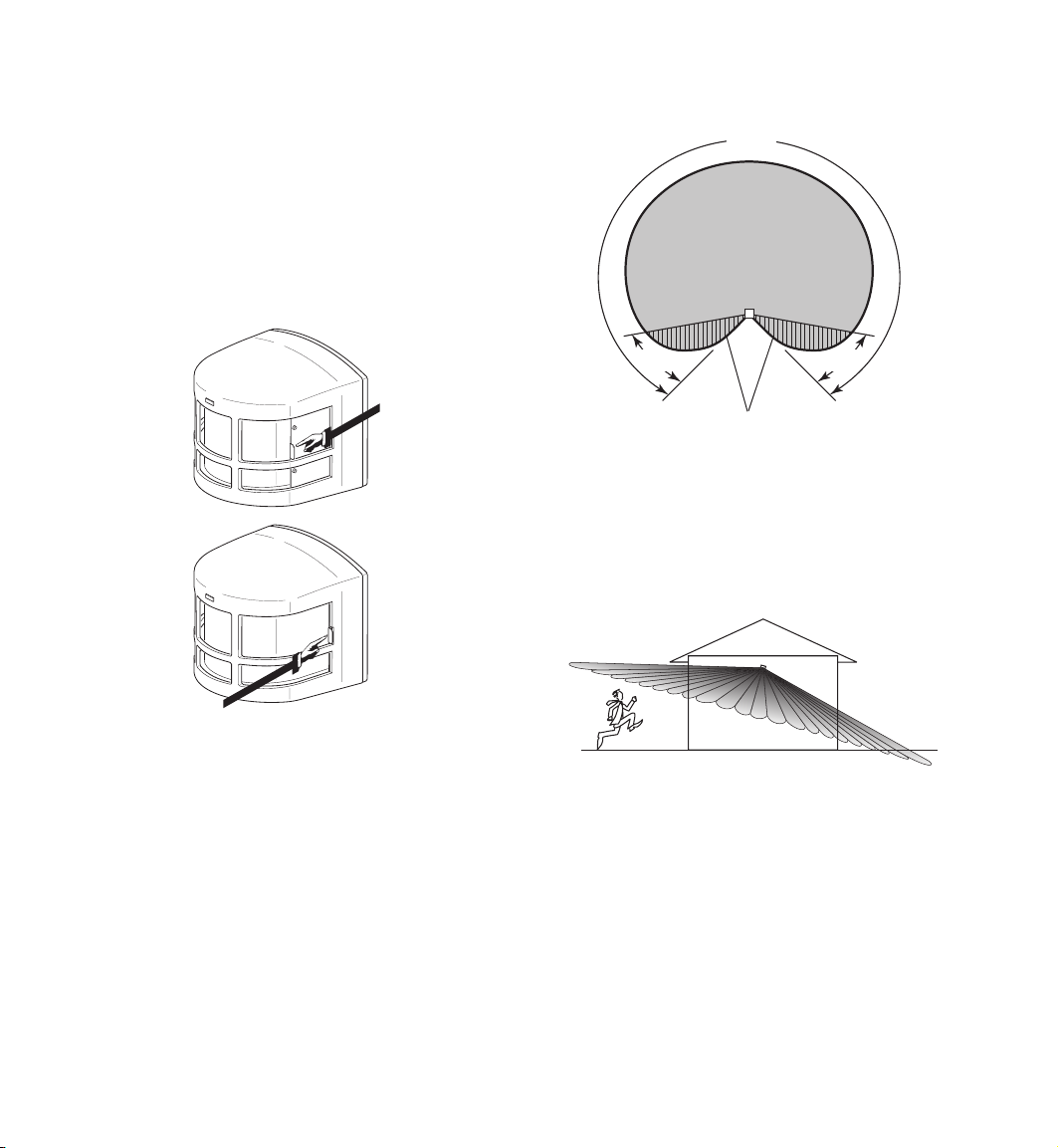
If the wide angle (270°) coverage is too wide for
your application, you may need to use one or both
shields to reduce the coverage angle.
❒
Decide which side of the lens you want to cover.
❒ Pull the lens shield out to block a portion of
the lens. Each lens shield will reduce the cov
erage area by approximately 35° when fully
extended.
Lens
Shield Fully
Extended
Maximum Coverage Angle
(Without Lens Shield)
270°
-
35° 35°
Approximate Area
Blocked with Lens Shield
Fully Extended
If the sensor is not kept level you may experience
an apparent decrease in range because objects
may pass under the detection zone without be
ing detected.
-
Lens Shield
Fully Recessed
598-1188-02
-11-
Operation
MANUAL MODE
AUTO
TEST
B
O
O
S
T
MIN
RANGE
MAX
ON-TIME
TEST 1 5 20
ON-TIME
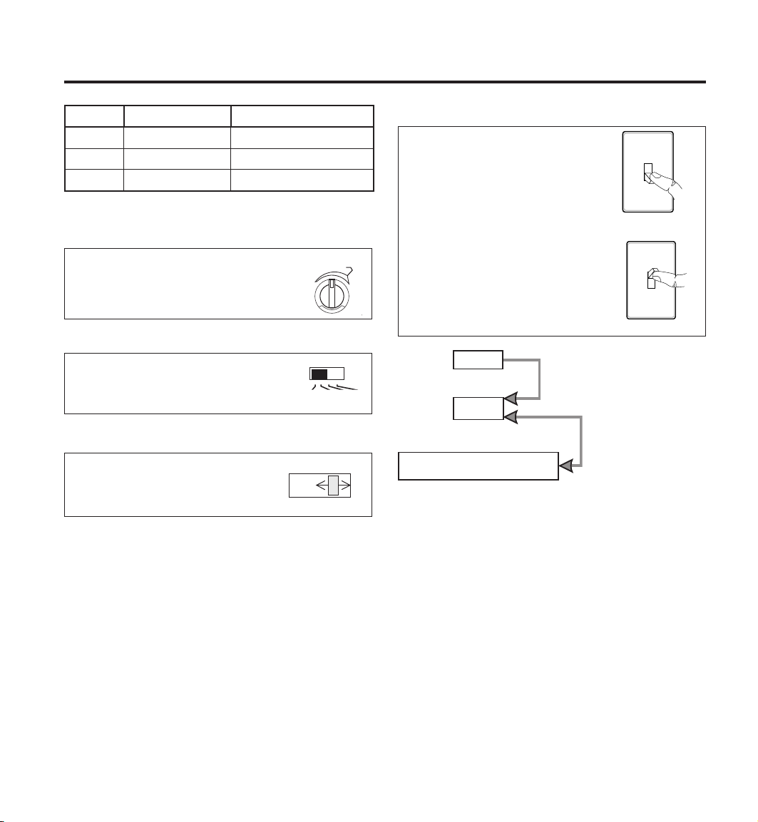
Mode: On-Time: Works: Day Night
Test
Auto
Manual
5 Sec x x
1, 5, or 20 min. x
Until Dawn* x
* resets to Auto Mode at dawn.
RANGE
Turn Range control to the desired
setting.
TEST MODE
Slide the ON-TIME switch to
TEST and turn the Range control
to the center of its adjustment.
AUTO MODE
Put the ON-TIME switch in the 1,
5, or 20 minute position.
ON TIME
TEST 1 5 20
MANUAL MODE
Manual Mode only works at
night because daylight returns
the sensor to AUTO.
Flip the light switch off for one
second then back on to toggle
between AUTO and MANUAL
1 Second OFF
then...
MODE.
Manual Mode only works with
the ON-TIME switch in the 1,
5, or 20 minute position.
Move ON-TIME Switch
to 1, 5, or 20 minutes
... back on.
Flip light switch
off for one second
then back on*
* If you get confused while switching modes,
turn the power off for one minute, then back
on. After the calibration time, the control will
be in the AUTO mode.
-12-
598-1188-02

Troubleshooting Guide
SYMPTOM POSSIBLE CAUSE(S) CORRECTIVE ACTION(S)
Lights will not come on
Lights come on in
daylight
Lights come on for no
apparent reason
Lights stay on
continuously
Lights flash on and off
1. Light switch is turned off.
2. Flood light is loose or burned out.
3. Fuse is blown or circuit breaker is turned off.
4. Daylight turnoff is in effect.
5. Incorrect circuit wiring, if this is a new instal
lation.
6. Sensor does not detect objects in desired
area.
1. Control may be installed in a relatively dark
location.
2. Control is in Test.
1. Control may be sensing small animals or
automobile traffic.
2. Range is set too high.
1. A lamp is positioned too close to the sensor
or pointed at objects that cause the sensor
to trigger.
2. Control is pointed at a heat source like an
air vent, dryer vent, or brightly-painted heatreflective surface.
1. Heat or light from the lamps may be turning
the light control on and off.
2. Reflected heat from other objects are triggering the sensor.
3. Control is in warming up.
4. Control is in Test.
1. Turn light switch on.
2. Tighten or replace flood light.
3. Replace fuse or turn circuit breaker on.
4. Recheck after dark.
-
5. Check circuit wiring.
6. Re-aim sensor to cover desired area. In
crease Range Boost.
1. Relocate light fixture to another junction
box with increased amount of daylight.
2. Set control switch to an ON-TIME position.
1. Re-aim sensor or use lens shield.
2. Reduce range. Turn Range Boost off.
1. Aim the lamp away from the sensor or
objects.
2. Re-aim sensor or use lens shield. Turn
Range Boost off.
1. Aim lamps away from the sensor. Turn
Range Boost off.
2. Re-aim sensor. Turn Range Boost off.
3. Flashing is normal under these conditions.
Wait 1 minute for sensor to warm up.
4. Set control switch to an ON-TIME position.
-
598-1188-02
-13-
 Loading...