

Heat & Glo GFK10 Fan Kit Installation Instructions
TM
Installation
TM
Instructions
Models:
GFK10 Fan Kit
The GFK10 Fan Kit has been designed to circulate room air through the appliance to enhance heat output. The fan kit operates on 120VAC, 60 Hz power. This is available through a receptacle in the factory-installed junction box. The junction box
is located in the controls compartment of the appliance.
A control module is provided with the fan kit which automatically turns the fan on and of f at preset times and is equipped wth
a variable speed control to provide a quiet forced air fl ow at the desired speeds.
Check with your local building code agency before you begin installation to ensure compliance with local codes, including
the need for permits and follow-up inspections. If you encounter any problems regarding code approvals, or if you need
clarifi cation of any of the instructions contained here, contact your Hearth & Home Technologies Inc. dealer. For the dealer
nearest you, please visit www.hearthnhome.com.
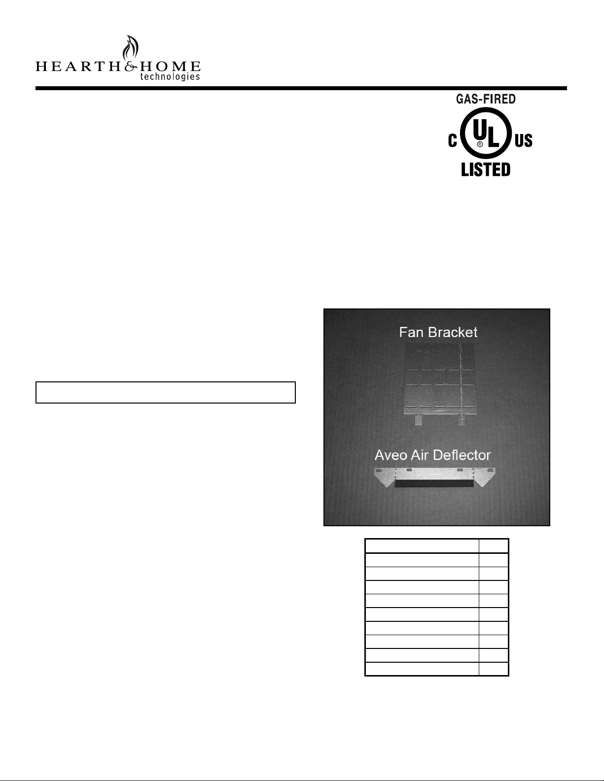
Check Contents of Shipping Carton
Compare contents of carton in Table 1 with the actual parts
received. If any parts are missing or damaged, contact your
dealer before starting installation. Do not install a damaged
fan kit.
Note: You may not need all parts included with this kit.
Installation Precautions
The GFK10 Fan Kit is tested and safe when installed in accordance with this installation manual. It is your responsibility to read all instructions before starting installation and to
follow these instructions carefully during installation to assure maximum benefi t from, and safe operation of, the fan.
NOTICE: This appliance must be electrically wired and
grounded in accordance with local codes or, in the absence
of local codes, with National Electric Code ANSI/NFPA 70-
latest edition or the Canadian Electric Code CSA C22.1
WARNING! Risk of Shock or Explosion! DO NOT wire IPI
controlled appliance junction box to a switched circuit. Incorrect wiring will override IPI safety lockout.
WARNING! Risk of Shock or Explosion! DO NOT wire
110V to the valve or to the appliance wall switch. Incorrect
wiring will damage controls.
WARNING! Risk of Fire and Electric Shock! Use ONLY
Hearth & Home Technologies-approved optional accessories with this appliance. Using non-listed accessories could
result in a safety hazard and will void the warranty.
CAUTION! Risk of Cuts/Abrasions/Flying Debris. Wear
protective gloves and safety glasses during installation.
Sheet metal edges are sharp.
Description Qty.
Fan 1
Screws 6
Foam Tape 1
Control Module 1
Electrical Cord 1
Magnetic Tape 1
Fan Bracket 1
Air Defl ector (Aveo only) 1
Jumper Wire (blue) 1
Table 1 Contents of Carton
Hearth & Home Technologies • GFK10 Fan Kit • 4016-136 • Rev D • 05/09
1
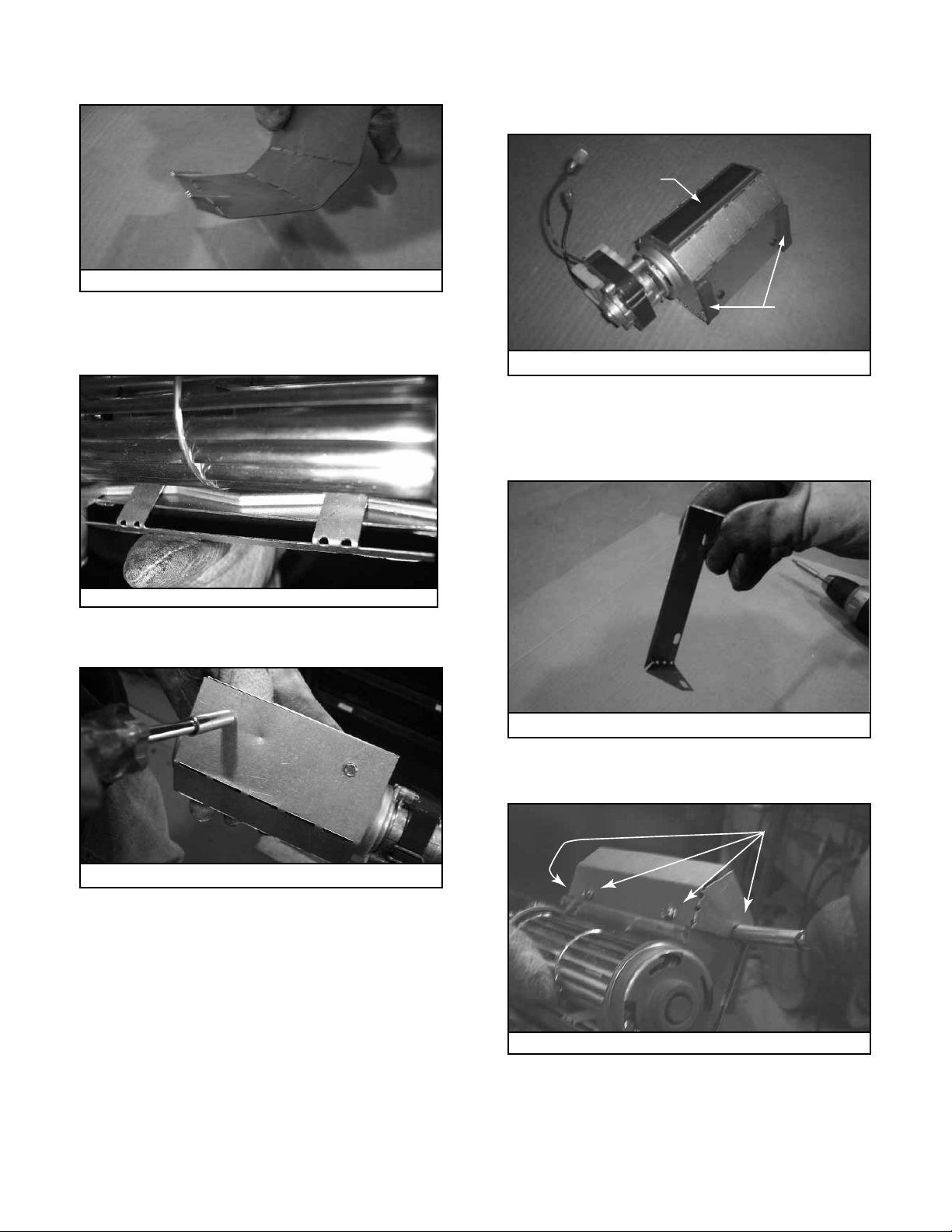
1. Fan Assembly
• Bend hand brakes of fan bracket as shown in Figure 1.
Figure 1
• Attach fan bracket by hooking hand brakes into open end
of fan as shown in Figure 2. Crimp down tight with pliers
so tabs do not interfere with rotor blades.
• Cut foam tape into two equal pieces.
• Apply magnetic tape and foam to fan bracket as shown
in Figure 4.
Magnetic
Tape
Foam
Figure 4
Note: The next two ste ps apply onl y if installing in th e
Aveo:
• Locate air defl ector and hand brake ends as shown in
Figure 5.
Figure 2
• Secure bracket to fan with two screws as shown in
Figure 3.
Figure 3
Figure 5
• Secure the air defl ector with four screws as shown in
Figure 6.
Secure with 4 screws
Figure 6
The following steps apply to all installations:
• Attach power supply cord to terminals of fan motor. Attach
ground wire to fan body with screw.
2
Hearth & Home Technologies • GFK10 Fan Kit • 4016-136 • Rev D • 05/09
 Loading...