

Page 1

User Manual
Flextight X5 / X1
English – v/1.3
Page 2

Table of contents
Wa rn ings and Re st ricti on s 4
Sy st em Re quire me nts 4
Par ts an d compo ne nts 5
Fr o nt p an el 5
B ac k pa ne l a nd c ut a wa y vi ew 6
Set ti ng up t he Sc an ner 7
En v ir on me n ta l Re qu i re me nt s
E le ct r ic al R eq u ir em en t s
I ns ta ll at i on P ro ce d ur e, F ir eW i re I nt er f ac e
Ope ra ting In str uc ti ons 9
Res ol ut ion s 10
Tr ue Re so lu ti o ns
Cal ib rati ng the Scan ne r 11
Fo c us C al i br at io n 12
W hi te C al i br at io n f or R ef l ec ti ve s 13
The Ligh t Tubes 14
Cle an ing t he Ex te rn al S ur face of th e Scann er 16
Dis po sal 16
Techn ic al Sp ec if ica ti ons 16
FC C Not ic e 17
CE - Dec la ratio n of co nfo rm ity 18
Fl e xt ig h t X1 18
Fl e xt ig h t X5 19
Page 3

The Flextight X1 and the Flextight X5 satisfy the demand
for image quality and speed requirements from professional photographers and production environments alike.
Developed around Hasselblad’s patented virtual drum
design and exible magnetic holder and incorporating a
3x8000 optic CCD sensor and a Linos (Rodenstock) lens,
both scanners are fast, easy-to-use and oer unparalleled
image quality. They also feature a new time-saving facility
– an ‘Auto Scan’ button, which with one press automatically delivers a superb, high resolution scan.
The Flextight X1 scans 35mm originals at a maximum
non-interpolated optical resolution of 6300 dpi at a maximum speed of 60MB per minute while the Flextight X5
scans 35mm originals at up to 8000 dpi and at 300MB per
minute, making it the world’s fastest, high-end scanner.
The Flextight X5 also has an A4 reective scanning option, can take a batch or a slide feeder and incorporates
Hasselblad’s active cooling capability, where an electronic
device is placed directly on the CCD to cool it down and
prevent an increase in electrical noise.
As with all Hasselblad scanners, the Flextight X1 and
Flextight X5 oer outstanding sharpness and image quality and are designed to bring out the nest details and
the full tonal range from the professional photographer’s
negatives or transparencies. Both Flextight models oer a
maximum non-interpolated, optical resolution of 3200 dpi
in true 8 or 16 bit colour from 60mm originals and 2040
dpi from 4” x 5” originals, both positive and negative. The
two scanners also provide automatic frame detection,
batch scanning, automatic focus and calibration, hardware (Flextight X5 only) and software-based Auto Dust
Removal and both utilize Hasselblad’s unique FlexColor
software and 3F – Flexible File Format. These features produce a digital data management system to provide users
with a fully integrated workow solution that spans from
image capture to output. Both scanners are PC and Mac
compatible using a FireWire interface.
The Flextight scanners also include a full selection of holders for mounting all of the most common original formats
without requiring gel, tape or glass plates and include a
full selection of the most common negative lm set-up
proles. Support for special formats, such as panoramas,
can also be customised and supplied by Hasselblad. The
scanners use glass-free original holders that ‘ex’ the
original during the scanning process to form a completely
straight line that places nothing between the original and
the electronic image sensor. This ensures that the quality
remains at its highest level without glass distortions and
other unwanted artifacts.
For the optimum in investment security, a Flextight X1
can be modied and upgraded to a Flextight X5 model at
a later date for approximately the dierence in price between the two scanners. Either way you can rest
assured you have made the right choice.
The supreme Hasselblad potential is there,
it’s up to you to exploit it!
3
Page 4

Warnings and restrictions
• Read all of the included documentation before attempting to install and use the
scanner.
• Do not touch the originals and/or the original holder while scanning.
• Do not start scanning or previewing until an original holder with an original has
been mounted.
• e original holder is only to be mounted or removed when the drum is in the load
position.
• When you turn on the scanner, the drum will roll to the load position, if it is not
there already. Do not touch the scanner while the drum is rotating.
• Do not place your fingers or any other object into the scanner while it is connected
to power.
• Before servicing or opening the scanner, the power supply must be disconnected
from the mains (unplugged). It is not sufficient simply to press the on/off button.
• Install the scanner in a location where children can not get to it. It contains small
openings and moving parts that can cause injury.
System requirements
Below are the basic hardware requirements for the PC or Macintosh system to which
the scanner is to be connected. For information about the processor, operating
system, RAM and harddisk requirements please refer to the “Soware Reference”
manual, that comes with the FlexColor soware.
• Screen resolution of minimum 800 x 600 pixels with true colors (24-bits).
• Mouse or other pointing device.
• FireWire interface.
Preventive maintenance
All Flextight scanners should be serviced every 25,000 scans or every 12 months,
whichever comes first. If a Feeder is mounted, the recommended number of scans is
15,000 provided that the feeder is mounted for all scans. Please note that previews are
also counted as scans.
Newer Flextight scanners have a counter installed so that the number of scans can be
monitored from FlexColor. Please refer to the FlexColor manual to learn more about
monitoring the number of scans.
Failures or faults originating from lack of service and/or daily maintenance are not
covered by the factory warranty.
4
Page 5
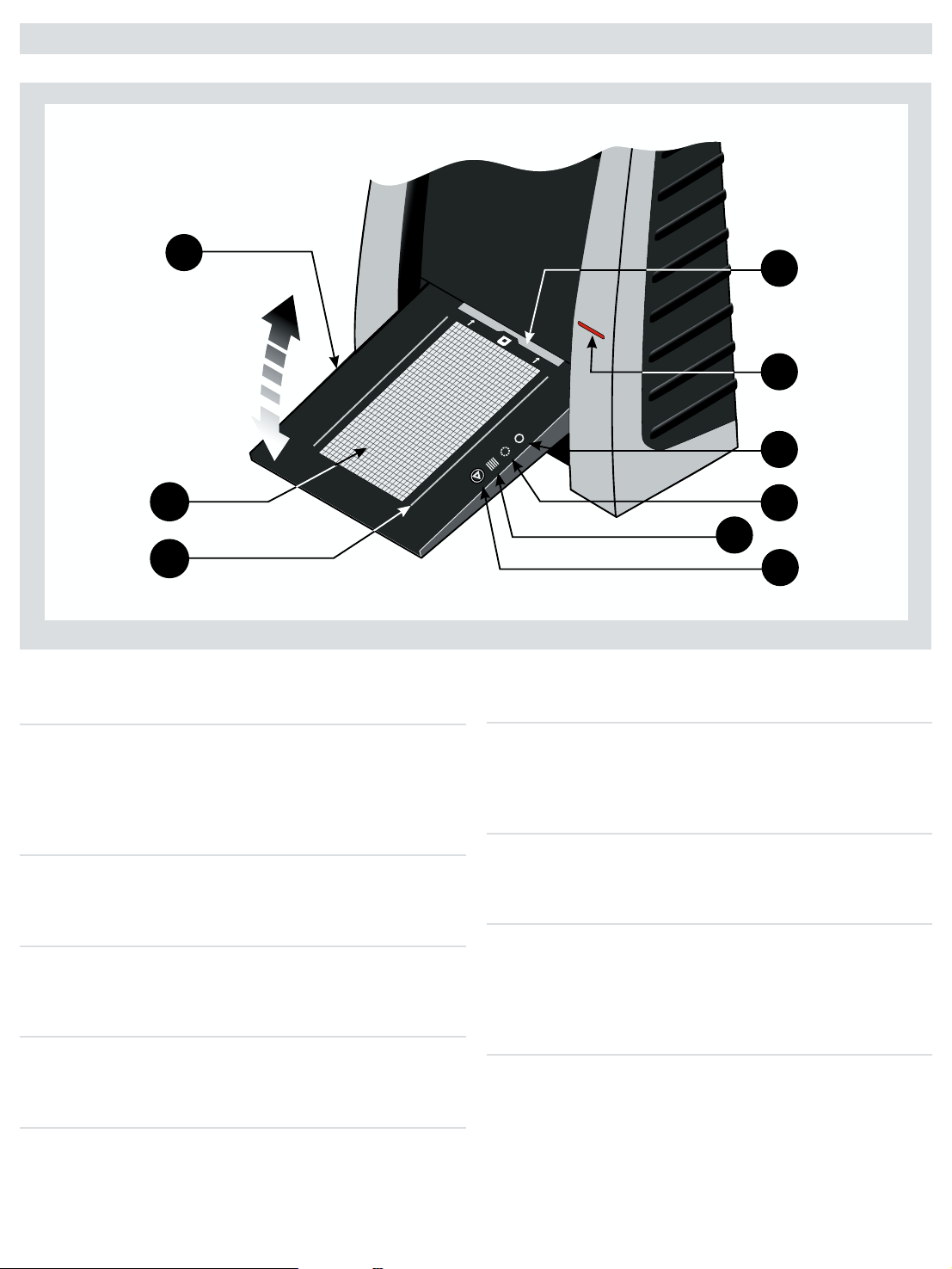
Parts and components − front panel
A
H
I
D
F
G
E
B
C
A Feed table
is must be in the lower position for normal scanning.
When scanner is not in use you can return it to closed
position to protect it from dust etc. Adjust to horizontal
position when using the 35 mm slide mount holder.
B Light table
For viewing originals. e grid helps you to align your
transparent originals.
C Transparency holder guide
Two rails that guide all the transparency holders and keep
them in a straight orientation.
D Original holder clasp
All original holders slide into a slot here and are held in
place by a magnetic clasp.
E Power switch
Button to turn the unit on/off.
F Power indicator (Green)
Remains lit when ready to scan. Flashes when first installed
to indicate that firmware must be loaded (it will be loaded
automatically when you run FlexColor).
G Motor drive indicator (Yellow)
Lights when the scanner is repositioning the optics to scan
in a new format or when drum is repositioning.
H Scan indicator (Red)
Lights when scanning. Do not touch the scanner while this
indicator is lit. If the light is flashing when not scanning,
then an error has occurred - please contact your Flextight
dealer for assistance.
I Start/stop scan button
With this button you can initiate a 3F scan. Parameters are
set according to your 3F scan setup. e button will also
stop any normal scan process.
5
Page 6
FL
E
X
T
I
G
H
T
O
R
I
G
I
N
AL
HO
LD
E
R P
A
TE
NT
PE
N
D
I
N
G
A
B
C
D
F
E
G
H
B
A
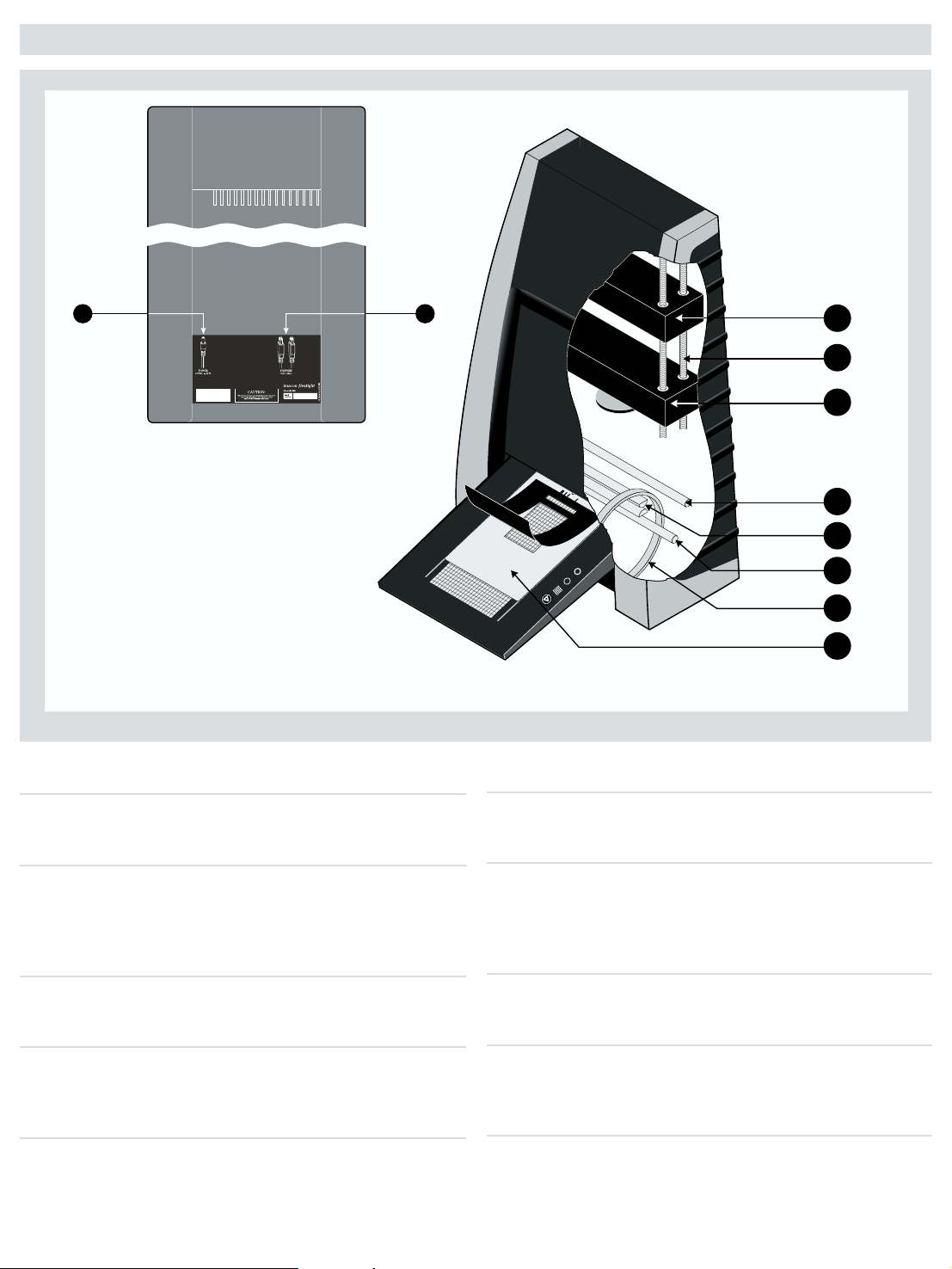
Parts and components − cutaway view
A Power cable socket
Connect the power cable into this socket.
B FireWire interface sockets
Socket for FireWire cable (max. 6 m) for computer connection. e second socket allows connection to another
device (hard disk, printer etc.) in the FireWire chain.
C CCD housing
Movable platform holding the CCD sensor.
D Spindle
For positioning of the CCD housing and optics housing for
the appropriate resolution and original size.
E Optics housing
Movable platform holding the optics that focuses the image
of the original on the CCD-sensor.
F Upper light source
Illuminates reflective originals. Flextigh X5 only.
G Prism-module
Focuses the light from various angles and thereby removes
or heavily reduces dust and scratches in the scanned image.
Flextigh X5 only.
H Lower light source
Illuminates transparent originals.
I Drum
Rotates the original into the scanner and transports it past
the optical scan line.
J Original holder
In this case, a transparency holder is shown in the
mounted position and with the retaining flap held open.
6
Page 7

Setting up the scanner
Environmental requirements
Set up the scanner in a location that fulfils the following requirements:
• Keep the scanner away from sources of heat, such as direct sunlight or a radiator.
Warm temperatures will degrade the quality of your scans - for best results, work in
a cool environment.
• e scanner must be operated away from sources of strong electromagnetic inter
ference. Although the scanner complies with all regulations governing electromagnetic immunity and every reasonable step has been taken to make the unit immune
to electromagnetic interference, it is still a precision electronic device and therefore
strong radio waves could interfere with your scans.
• e surface on which the scanner is placed must be stable and free from vibrations.
If the scanner is shaken or moved while scanning, your results may be affected.
• If the scanner has been in a colder environment (e.g. outside or in storage) just be
fore set up in a warmer room, then wait about two hours before using it - otherwise,
condensation may form, which will prevent the scanner from operating correctly.
• Avoid using the scanner in areas where there is a high level of dust.
Electrical requirements
e Flextight power supply requires a mains voltage of between 100 and 240 V AC at
a frequency of 50 to 60 Hz. is is within the normal wall-socket power standards of
most countries. Do not attempt to use Flextight with any power source outside the
specified range. e scanner and all devices attached to the scanner (computer, monitor, FireWire devices, etc.) must be grounded (i.e. use a three-point electrical connection). Note that the power supply may emit a low hissing sound when plugged in but
not connected to the scanner. is is normal and will not damage the power supply or
scanner.
-
-
Installation procedure − FireWire interface
Proceed as follows:
1. Place the scanner on a table near your computer with the front facing away from
you. Make sure that the location you choose meets all environmental and electrical
requirements.
2. When using a FireWire interface connection, it is not necessary to switch of your
computer and other connected units. Connect a FireWire cable from one of the
FireWire connectors on your scanner (see Back Panel on page 6) to either the computer’s FireWire connector or to a free FireWire connector on any other FireWire
device already connected to your computer.
3. Connect the round connector from your power supply to the power supply socket
on the back of the scanner (see Back Panel on page 6).
IMPORTANT: Make sure that the wall socket you are planning to use meets the
electrical requirements outlined earlier. Plug the Flextight X1 / X5 power supply
into a wall socket. Note that the power supply may emit a low buzzing sound when
plugged in. This is normal and will not damage the power supply or scanner.
4. Turn the scanner around so that the front is facing you.
5. Your system is assembled. Turn on your computer and install the FlexColor image
scanning software.
7
Page 8

Closed
Horizontal
Normal
A
BKL
C
F
LE
X
T
I
G
HT
O
R
I
G
IN
A
L
HO
L
DE
R
P
A
TE
N
T
PEN
D
IN
G
I
J
D
E
G
H
F
For horizontal positioning lift the table
free from the hinges and push.
8
Page 9

Operating instructions
A
BKL
C
F
LE
X
T
I
G
HT
O
R
IG
IN
A
L
HO
L
D
ER
P
A
TE
N
T
PEN
D
IN
G
I
J
D
E
G
H
F
1. It is assumed that the scanner and FlexColor software have
been properly installed.
2. If not already done, lower the feed table
3. Press the red power button
F on the front of the scanner to
switch it on. The green light G starts ashing. This means that
no rmware has been downloaded yet. It will be downloaded
automatically later when you rst run the FlexColor program.
4. Turn on your computer and start the FlexColor program. The
green light G will stop ashing indicating that rmware has
been downloaded to the scanner.
5. Select the original holder
K that matches your original:
• For transparencies, choose one of the holders that has a
square hole in it. The original must completely ll the hole with
no edges showing. Also, no edges of the original must extend
past the outer edges of the holder.
• For reectives, select the large A4/letter-size holder with the
clear plastic layer. The feed table A must be in normal position.
• For 35 mm slide frames use the optional 35 mm slide mount
holder. The feed table A must be adjusted to horizontal position (see diagram). This is obtained by lifting the table slightly
upwards while pushing it gently into the scanner.
NOTE! Each original holder has it’s own unique identication
code (a combination of small rectangular holes at the holder’s
leading edge). These codes, combined with the scanner’s ability to detect the feed table position, ensure that the scanner will
not operate unless the feed table position matches the selected
original holder.
6. Place the original holder
K with the slotted tab facing into the
scanner. For transparencies, the exible magnetic retaining
ap must face upwards. For reectives, the clear plastic sheet
must face upwards. Make sure that the original holder ts
between the appropriate guides C or D on both sides of the
light table.
7. Slide the holder gently into the slot
table. It will slip about ½ cm (¼ inch) into it. Do not press too
hard. It slips in very easily and is held in place by a magnetic
clasp. To remove the holder, simply pull it gently backwards.
8. Lift the retaining ap of the original holder and place your
original L as follows:
• For transparencies, place your original with the emulsion side
down. The original must completely ll the hole with no edges
showing and with a minimum overlap of 2 mm along each
edge. Also, no edges of the original must extend past the outer
edges of the holder. Use the grid on the light table B to help
line up the image.
For transparency holders, the top retaing ap is magnetic,
which will hold the original fast.
• For reectives (Flextight X5 only), make sure that no part of the
original extends past the edge of the holder. Use the dotted
A to normal position.
E at the top of the feed
9
Page 10

lines printed on the holder to line up the image. Handle the clear plastic layer only
! " #
by the edges to avoid ngerprints. Curl the plastic layer back and slip the front edge
into Flextight’s foil holder.
9. Lay the top layer of the holder down at over the original.
• For the reective holder, note the four metal pegs (the top two are shown as
C in the gure below); make sure that the clear plastic sheet is pressed all the way
down over all four pegs. Note also the two curved tabs at the top of the holder (B in
the gure below); the clear sheet must slip under each of these tabs, as shown.
10. Go to your computer and follow the directions given in the FlexColor software
manual to take a preview, make settings, and take the nal scan. Alternatively you
can press the scan button on the light table. This will initiate a 3F scan according to
your 3F settings.
A and
Resolutions
True Resolutions
e table below shows the max. resolutions (in ppi) available with each of the original
holders when scanning in True Resolutions mode.
Original Max. resolution (ppi) at full scanning width.
35 mm Portrait 8000 (Flextight X5) 6300 (Flextight X1)
35 mm Landscape 5000
45 x 60 mm Portrait 4000
60 x 60 - 60 x 70 mm 3200
4” x 5” Portrait 2040
A4 Portrait 960
Table 1: True Resolutions
10
Page 11

Calibrating the scanner
e Flextight X5 scanner requires two types of calibration e Flextight X1 only
requires one:
• Both scanners require focus calibration. Focus calibration adjusts the positioning
of the scanners’ optics for each zoom level. If your scans appear unfocused or are
slightly the wrong size, then you may need to make a new focus calibration to adjust
the zoom mechanism. e focus calibration is stored in the scanners flash PROM, so
it is retained when you move the scanner to a new computer. See
on page 12 for more information.
• White calibration is only required for reflective scans (it is done automatically for
transparencies). During calibration, the scanner scans a white target to establish the
white point along the full length of the scanners CCD. See
Reectives on page 13 for more information.
Both of the calibration procedures are simple and are initiated from the FlexColor
program.
Focus Calibration
White Calibration for
11
Page 12

Focus calibration
e Flextight scanner uses an adjustable zoom and focus mechanism to
optimize its scanning resolution for each of the original formats it can handle. If you
suspect your scans are not as sharp as they should be, then you may need to calibrate
your scanner. Note that you must not calibrate the scanner every day. It is intended
that the scanner is calibrated not more than once every three months. In most cases,
this procedure will never be necessary.
Use procedure below to make
1. Locate the Focus sheet that came with your scanner. It is a 8 x 9 cm (3” x 3.5”)
square of transparent black and white lm.
2. Mount the lm into the 6 x 6 original holder with the text reading normally as
shown. Place the sheet as straight as possible. Use the scanners light table grid and
the corners marked on the sheet to help align it.
Focus Calibration:
3. Select
4. Click on the
5. When the focus calibration is nalized, you will get a message saying that the cali
e scanner is now calibrated for all resolutions and for both transparent and
reflective originals.
Focus Calibration from the Maintenance menu.
Calibrate button, and the focus calibration starts.
bration was succesfull. Click OK..
12
-
Page 13

White calibration for reflectives
e Flextight X5 scanner uses a white reference to make sure that all elements in the
scanner’s CCD react consistently to light brightnesses. e scanner has been calibrated at the factory, and the calibration data is stored in the scanner’s flash PROM.
As the scanner ages, the properties of the light tubes may change slightly. erefore,
you must redo the white calibration every six months or so and immediately aer
changing the light tubes.
Use the procedure below to make a White Calibration:
1. Find the white calibration sheet that came with the scanner. It is a square white
piece of paper (219 x 219 mm (8.6” x 8.6”)). If you have lost the white calibration
sheet, then you can use a at (non-textured), perfectly white piece of paper of the
same dimensions.
2. Your scanner came with several clear plastic layers for the reective original holder.
If you have used the reective holder before, make sure that there are no nger
prints or other marks on the plastic layer. Replace the layer with a new one if
necessary.
3. Align the top edge of the sheet with the dotted line near the top of the original
holder (see the gure below). Align each side of the target with the edges of the
original holder.
4. Select
5. Click on
White Calibration from the Maintenance window. The External White
Calibration window appears.
Calibrate. The scanner will take several scans of the white target and the
whole process will take about eight minutes.
13
Page 14

The light tubes
e Flextight X5 contains two light tubes: one for illuminating reflective originals
from above, the other for shining light through transparencies from below. e
Flextight X1 has only one light tube for transparency scanning.
NOTE! e two lamps are of different types and are not interchangeable.
Replacing the light tubes
If scans are suddenly coming out black (or all white if you are scanning negatives),
then one of your light tubes may be defective. Make a preview using both types of
scans (transparent and reflective) to find out which tube is affected.
• If transparencies are not working, then the bottom tube may be burned out.
• If reflectives are not working, then the top tube may be burned out.
Follow the procedure below to replace a tube:
(See Figure on next page)
1. Obtain the appropriate replacement lamp (ask your Flextight dealer).
2. Turn o and unplug the scanner from the primary power supply.
3.
IMPORTANT: Let the light tubes cool down for approx. 10 minutes before
proceeding.
3. Remove the two allen screws
Do not remove any other screws.
4. Press the back panel down (app. 5 mm) and lift out using the handle
5. Turn the feed table to upright position.
6. Locate the tube to be replaced and dismount the plug
7. Remove the defective tube:
• Press the aps backwards to release the tube
• Pull the tube gently out of the holders and then sideways out of the scanner.
8. If you are replacing the transparencies tube, you need to disassemble the tube from
the sockets as well:
• Remove the screw
• Remove the right socket
screwdriver to loosen this socket).
• Assemble the new tube with the sockets.
9. Insert the replacement tube and mount it into the holders making sure that it is
properly held in place by the aps.
10. Connect the plug
11.
IMPORTANT: The “T” on the lamp board cover D indicates the socket for the
transparencies tube.
12. Lower the feed table
13. Mount the back panel and the two allen screws following the reverse of the
procedure used when removing them.
14. Turn on the scanner and check function of the new tube.
F to release the left socket G.
C.
E.
A (one in each side) using a 2.5 mm Allen key.
B
C.
E.
H by simply pulling it o (you may need to use a small
14
Page 15

PRESS
PULL OUT
PULL OUT
PRESS
A
B
D
C
E
G
H
F
A
15
Page 16

Cleaning the external surface of the scanner
e external surface of the scanner can be cleaned with a damp cloth. Be careful not
to allow any moisture inside the scanner or on any of the connectors. Do not use
alcohol or other solvents.
Disposal
If you need to dispose of the scanner, it must be delivered to an authorized waste
plant for electronics equipment.
Technical specifications
Power Connector
Power Consumption
Max. 75 W during operation
Power Requirements
100-240V AC, 1.3 A, 50-60 Hz
Interface to Computer FireWire (IEEE 1394)
Front Panel
One multifunction switch (on/off switch)
Status indicator LED’s
Drum Force 1 kg (2.2 lbs)
Operating Environment
Operating Temperature: 10 - 35 °C (50 - 95 °F)
Recommended Working Temperature: 10 - 25 °C (50 - 77 °F)
Humidity: 20 - 80 % RH (no condensation)
Storage Environment
Temperature: 0 - 50 °C (32 - 122 °F)
Relative humidity: 20 - 80 % RH (no condensation)
Originals
Transparencies: from 35 mm to 4 x 5 inches, < 1 mm thick
Reflectives: up to 220 x 310 mm (A4 oversize), < 1 mm thick (X5 only)
Standard 35 mm dias in frames (optional)
Lamp type
Reflectives Lamp (for Flextight X5): Part No. 10700022
Transparency lamp for Flextight X5: 10700032
Tranparency lamp for Flextight X1: 10700022
Dimensions
Height: 645 mm (25.4”)
Width: 385 mm (15.2”)
Depth: 220 mm (8.7”) (feed table closed) 440 mm (17.3”) (feed table open)
Weight: 20,5 kg (46 lbs)
16
Page 17

FCC Notice
is equipment has been tested and found to comply with the limits for a Class A
digital device, pursuant to Part 15 of the FCC Rules. ese limits are designed to
provide reasonable protection against harmful interference when the equipment is
operated in a commercial environment. is equipment generates, uses, and can
radiate radio frequency energy and, if not installed and used in accordance with
the instruction manual, may cause harmful interference to radio communications.
Operation of this equipment in a residential area is likely to cause harmful interference in which case the user will be required to correct the interference at their own
expense.
17
Page 18

CE – Declaration of conformity
18
Page 19

CE – Declaration of conformity
19
Page 20

© 2006 Hasselblad A/S. All rights reserved.
Flextight X1 / X5 User’s Guide, Part No 75020123, revision 1.3
e information in this manual is furnished for informational use only,
is subject to change without notice, and should not be construed as a
commitment by Hasselblad A/S.
Hasselblad A/S assumes no responsibility or liability for any errors or
inaccuracies that may appear in this manual. Hasselblad A/S assumes no
responsibility or liability for loss or damage incurred during or as a result
of using Hasselblad soware or products.
Hasselblad, Imacon, FlexColor and Flextight are trademarks of
Hasselblad A/S. Macintosh, Mac OS and FireWire are registered trade
marks of Apple Computer, Inc.
-
 Loading...