

Page 1
Harman/kardon HT 32" 40" 46"
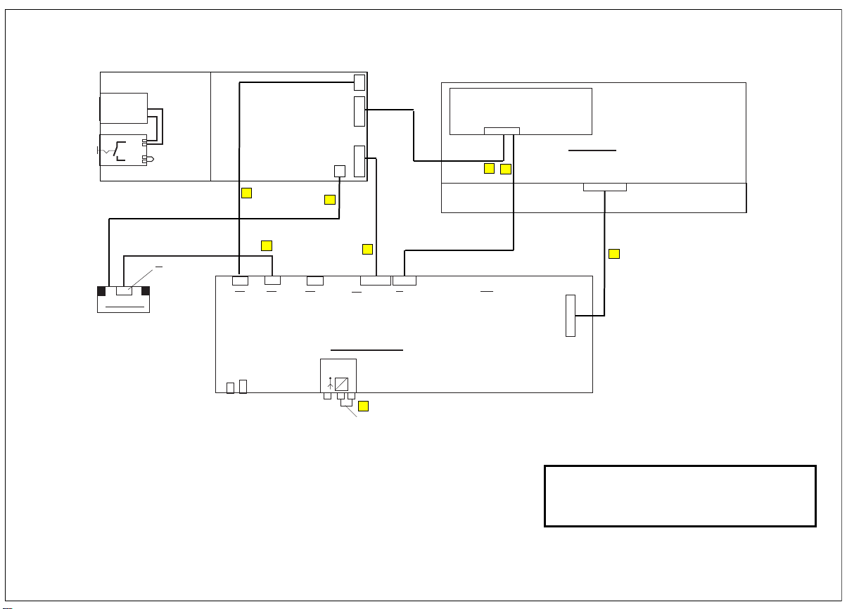
HT32v1 wire diagram
AC power
line
Power Input
Power Switch
X1
IR-Receiver
1a
2a
1
2
IR-control
cable - 20pol
X1
1-2 = n.c.
3 = LED AMBER
4 = LED BLUE
5-12 = n.c.
13 = NC
14 = NC
15 = NC
16 = NC
17 = NC
18 = GND
19 = 5V
20 = IR-RCVR
Power Supply
C4
K12
K12
Audio
Power in
1,2 GND
3,4 30V
2-3 GND
1 Signal
2 GND
1 Signal
R
K8
K9
L
C6
K25
K25
1/7 GND
11 GND
12/18 GND
3 LED red
4 LEDgreen
2/5/6 n.c.
8/10 n.c.
9 BLON
13 S5
14 S4
15 S3
16 S2
17 S1
19 +5VST
20 IRRCVR
CN4
C5
K
K
1
2
3
4
5
6
7
Signal processing
PIPTuner
f1
f2
CN1
CN3
CN2
C3
K22
K22
1/2 +24V/12VS
3 +5V PD/SD
4/6/8 G ND
5/7 +5V
9 +12VA
10 PSSTDBY
11 PSDPMS
12
C7
RF-loop cable
CN3
1/2/3/4/5 +24V
3/4/8/
6/7/8/9/10 GN D
11 nc
12 BL on/off
13 GND
14 Bright
CN2
1/2 +12V
3/4/8/
10/13 GND
5/6 +5V
7 +5VStby
9 Bright
11 BL on/off
12 Relay
K5
K5
1/2 NC
3/6/12 G ND
4/5 NC
7/8 +5VSW
9NC
10 NC
11 NC
DC power line/
control backlight
cable -
1 - 5 24V
2 -10 GND
11 n.c.
12 BL on/off (BLTC)
13 Vdim (BRT2)
14 PWM dim
Power backlight
cable
C2
CN2:
1 LI01
2 LI02
3 LVDSOD05 LVDSOD0+
4 LVDSED06 LVDSED0+
7/8 GND
9 LVDSED112 LVDSED1+
13/14 G ND
15 LVDSOD217 LVDSOD2+
16 LVDSED218 LVDSED2+
19/20 GND
21 LVDSOCK23 LVDSOCK+
22 LVDSECK24 LVDSECK+
C2
Backlight
28 LVDSOD325/26 GND
27 LVDSOD329 LVDSOD3+
28 LVDSED330 LVDSED3+
31/32 GND
33 LVDSOD435 LVDSOD4+
34 LVDSED436 LVDSED4+
37 LO1-5V
38 LIO4
39 LIO3
40 SDA
42 SCL
41/43/45 +5VPNL
47/49 +5VPNL
44/46/48/50 GND
TFT Display
TFT-Signal
CNI1
LVDS - cable
CN2
1
1
1
1
1
1
C1
.
European liaison office: 2, route de Tours, 72500 Château du Loir, France
tel: +33 (0)2 43 38 43 00 fax: +33 (0)2 43 44 93 83 www.harman.com
Harman Consumer Group International is a trading style of
JBL, Incorporated, 8500 Balboa Boulevard, Northridge, CA 91329, USA.
Page 2
Protective
harman/kardon
HT 32" 40" 46"
European liaison office: 2, route de Tours, 72500 Château du Loir, France
tel: +33 (0)2 43 38 43 00 fax: +33 (0)2 43 44 93 83 www.harman.com
Harman Consumer Group International is a trading style of
JBL, Incorporated, 8500 Balboa Boulevard, Northridge, CA 91329, USA.
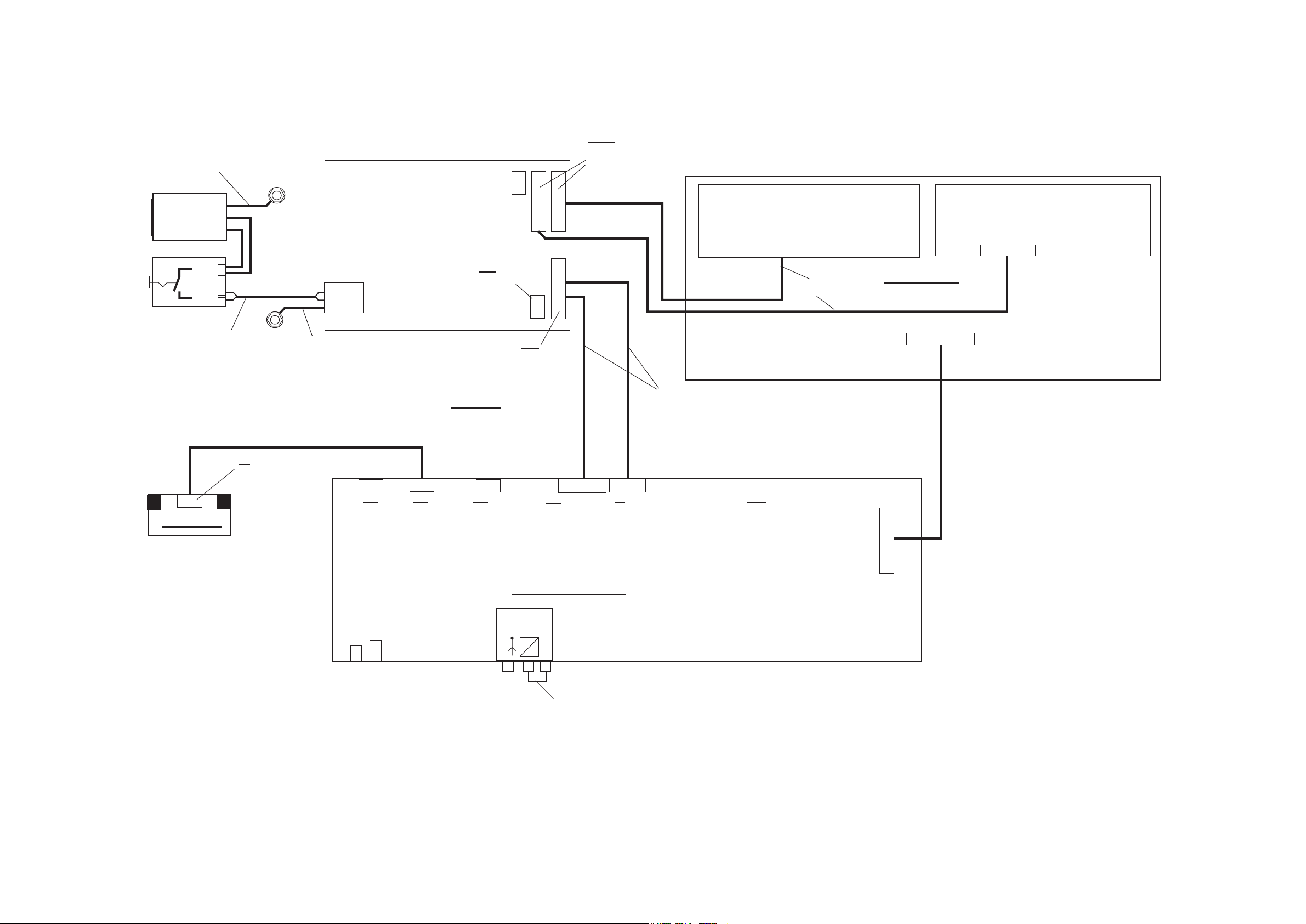
wire diagram HT32v2 HT40 & HT46"
C3
C2
C4
C1
C5
C7
earth cord
Power Input
Line Filter
Power Switch
Power cable
1a
2a
1
2
IR-control
cable - 20pol
AC power
line
Protective
earth cord
Power Supply
CN1
CN6
1 A+5V
2nc
3 A+12V
4/ 5 GND
Option: Fan
CN5
CN4
CN3
CN2
CN6
CN2
1/2 +12V
3/4/8/
10/13 GND
5/6 +5V
7 +5VStby
9 Bright
11 BL on/off
12 Relay
CN3+4
1/2/3/4/5 +24V
3/4/8/
6/7/8/9/10 GND
11 nc
12 BL on/off
13 GND
14 Bright
DC power line/
control backlight
cable - 13pol
1 - 5 24 V
2 -10 GND
11 n.c.
12 BL on/off (BLTC)
13 Vdim (BRT2)
14 PWM dim
J12
Power backlight
cable
Backlight 1
TFT Display
TFT-Signal
CNI1
1 - 5 24 V
2 -10 GND
11 n.c.
12 BL on/off (BLTC)
13 Vdim (BRT2)
14 PWM dim
J12
Backlight 2
X1
IR-Receiver
X1
1-2 = n.c.
3 = LED red
4 = LED green
5-12 = n.c.
13 = Taste S5
14 = Taste S4
15 = Taste S3
16 = Taste S2
17 = Taste S1
18 = GND
19 = 5V
20 = IR-RCVR
K22
K22
1/2 +24V/12VS
3 +5V PD/SD
4/6/8 GND
5/7 +5V
9 +12VA
10 PSSTDBY
11 PSDPMS
12
K5
K5
1/2 BCKPWM
3/6/12 GND
4/5 BCKLGHT
7/8 +5VSW
9 PNLIO3/GND
10 PNLIO4/GND
11 NC
CN2:
1 LI01
2 LI02
3 L VDSOD05 L VDSOD0+
4 L VDSED06 L VDSED0+
7/8 GND
9 L VDSED11 2 LVDSED1+
13/14 GND
15 LVDSOD21 7 LVDSOD2+
1 6 LVDSED21 8 LVDSED2+
19/20 GND
2 1 LVDSOCK23 LVDSOCK+
22 LVDSECK24 LVDSECK+
2 8 LVDSOD325/26 GND
2 7 LVDSOD329 LVDSOD3+
2 8 LVDSED33 0 LVDSED3+
31/32 GND
33 LVDSOD435 LVDSOD4+
34 LVDSED436 LVDSED4+
37 LO1-5V
38 LIO4
39 LIO3
40 SDA
42 SCL
41/43/45 +5VPNL
47/49 +5VPNL
44/46/48/50 GND
LVDS - cable
CN2
L
K25
K25
1/7 GND
11 GND
12/18 GND
3 LED red
4 LEDgreen
2/5/6 n.c.
8/10 n.c.
9 BLON
13 S5
14 S4
15 S3
16 S2
17 S1
19 +5VST
20 IRRCVR
K23
K23
1 ACPWDK
2 LOWVON
3 5VST
4 GND
5 HIGVDN
6 FPVRR
7 N.C.
Signal processing
PIPTuner
f1
f2
K12
K12
Audio
Power in
1,2 GND
3,4 30V
2-3 GND
1 Signal
2 GND
1 Signal
R
K8
K9
HF-cable
Page 3
Harman/kardon HT 32" 40" 46"
10g
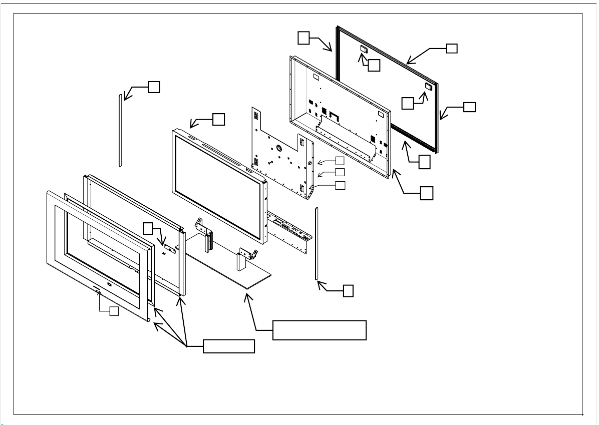
Exploded view HT32" 40" 46"
10h
10f
8
9*
7
1
2
4
12
5
10
10h
9*
9a
11
see part list for Break down of the separate
9*
*assembled in one part
parts included on the stand
European liaison office: 2, route de Tours, 72500 Château du Loir, France
tel: +33 (0)2 43 38 43 00 fax: +33 (0)2 43 44 93 83 www.harman.com
Harman Consumer Group International is a trading style of
JBL, Incorporated, 8500 Balboa Boulevard, Northridge, CA 91329, USA.
Page 4
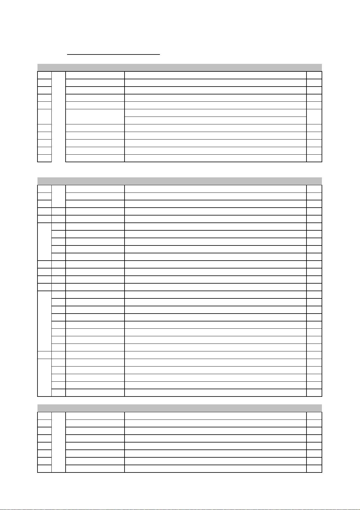
Spare Parts Lists
V1.1
Harman Kardon HT 46"
Electrical
Pos Part Number Description
1 2097-4600-2005 TFT-LCD MODULE 46" 1366x768 1
2 2198-0073-0005 SMPS HT32v2 HT40 HT46 1
4 4042-6350-0100 LP-Signal Processing / input / analog tuner 1
5 4042-6996-0200 LP-IR-Sensor, 2xLED, bl+amber front board HT 32 / 40 / 46 1
C1 2218-1000-0090X1 LVDS-cabel Samsung -W2-L01 (16:9) (CN2 AV5 / CNT1) 1
Power backlight cable (CN3/CN0001)
C2
C3 TBA AV5 supply cable (CN2/K22) 1
C4 TBA AV5 supply cable (CN4/K12) 1
C5 TBA Remote cable (CN4/LED Bd) 1
C6 TBA IR control cable (K25/X1) 1
C7 TBA Antenna cable (RF/PIP) 1
Pos Part Number Description
7 4042-3584-0001 Wall Mount Left 1
8 4042-3585-0001 Wall Mount Right 1
9 TBA Front Frame 46" Harman Kardon complete. 1
9a TBA Label Harman/Kardon 1
10 6046-R004-G210 Rear Cover HT 46" Harman Kardon 1
10a TBA Label - Input 1
10b TBA Label - safety / rating / sn (without SN) HT46 1
10c TBA Label - Caution HT46 1
10d TBA Screw black 13
10e TBA Screw silver 26
10f TBA Screw cover top edge HT46 1
10g TBA Screw cover bottom edge HT46 1
10h TBA Screw cover side edge HT46 2
11 6040-V163-F510 Table Stand mounted Harman Kardon HT40 HT46 1
11a TBA Stand Base Plate HT40/46 1
11b TBA Alu profile Black HT40/46 2
11c TBA Bracket Left 1
11d TBA Bracket Right 1
11e TBA Clear Rubber Feet's 6
11f TBA Headless screw (bracket/Alu profile) 2
11g TBA Screw (Plate/Alu profile) 2
11h TBA Screw (Bracket/Rear panel) 8
12 NA Main chassis HT 40" Harman Kardon 1
12a TBA Label Input HT40 1
12b TBA Tuner shield , cobber tape 2
12c TBA shield soft pad small 1
12d TBA Shield soft pad large 1
12e TBA Shield Clips (hdmi/main chassis) 1
Pos Part Number Description
13 2279-0001-0269 Brown Box 1
14 2279-0001-T102 Beauty Carton HT 46 side 1
15 2279-0001-T108 Beauty Carton HT 46 top 1
16 2279-0002-0232 End Pack EPS left down 1
17 2279-0002-0233 End Pack EPS right down 1
18 2279-0002-0234 End Pack EPS left up 1
19 2279-0002-0235 End Pack EPS right up 1
20 2218-0503-0150 RF Cable 1
TBA
Mechanical
Packing
DC power cable backlight (K5 p6.7.8 / CN0001)
1
Page 5
Spare Parts Lists
V1.1
Harman Kardon HT 40"
Electrical
Pos Part Number Description
1 2097-4000-2007 TFT-LCD MODULE 40" 1366x768 1
2 2198-0073-0005 SMPS HT32v2 HT40 HT46 1
4 4042-6350-0100 LP-Signal Processing / input / analog tuner 1
5 4042-6996-0200 LP-IR-Sensor, 2xLED, bl+amber front board HT 32 / 40 1
C1 2218-1000-0090X1 LVDS-cabel Samsung -W2-L01 (16:9) (CN2 AV5 / CNT1) 1
Power backlight cable (CN3/CN0001)
C2
C3 TBA AV5 supply cable (CN2/K22) 1
C4 TBA AV5 supply cable (CN4/K12) 1
C5 TBA Remote cable (CN4/LED Bd) 1
C6 TBA IR control cable (K25/X1) 1
C7 TBA Antenna cable (RF/PIP) 1
Pos Part Number Description
7 4042-3584-0001 Wall Mount Left 1
8 4042-3585-0001 Wall Mount Right 1
9 TBA Front Frame 40" Harman Kardon complete. 1
9a TBA Label Harman/Kardon 1
10 6040-R013-G210 Rear Cover HT 40" Harman Kardon 1
10a TBA Label - Input 1
10b TBA Label - safety / rating / sn (without SN) HT40 1
10c TBA Label - Caution HT40 1
10d TBA Screw black 13
10e TBA Screw silver 26
10f TBA Screw cover top edge HT40 1
10g TBA Screw cover bottom edge HT40 1
10h TBA Screw cover side edge HT40 2
11 6040-V163-F510 Table Stand mounted 40" Harman Kardon HT40 1
11a TBA Stand Base Plate HT40 1
11b TBA Alu profile Black HT40 2
11c TBA Bracket Left 1
11d TBA Bracket Right 1
11e TBA Clear Rubber Feet's 6
11f TBA Headless screw (bracket/Alu profile) 2
11g TBA Screw (Plate/Alu profile) 2
11h TBA Screw (Bracket/Rear panel) 8
12 NA Main chassis HT 40" Harman Kardon 1
12a TBA Label Input HT40 1
12b TBA Tuner shield , cobber tape 2
12c TBA shield soft pad small 1
12d TBA Shield soft pad large 1
12e TBA Shield Clips (hdmi/main chassis) 1
Pos Part Number Description
13 2279-0001-T101 Beauty Carton HT 40 A 1
14 2279-0001-T107 Beauty Carton HT 40 B 1
15 2279-0002-0232 End Pack EPS left down 1
16 2279-0002-0233 End Pack EPS right down 1
17 2279-0002-0234 End Pack EPS left up 1
18 2279-0002-0235 End Pack EPS right up 1
19 2218-0503-0150 RF Cable 1
TBA
Mechanical
Packing
DC power cable backlight (K5 p6.7.8 / CN0001)
1
Page 6
Spare Parts Lists
V1.2
Harman Kardon HT 32"
Electrical
Pos Part Number Description
1 2097-3200-2003 TFT-LCD MODULE HT 32" 1366 x 768 1
6030-6521-0000 SMPS HT32 (HT32-SN<CG002-03069) 1
2
4 4042-6350-0100 LP-Signal Processing / input / analog tuner 1
5 4042-6996-0200 LP-IR-Sensor, 2xLED, bl+amber front board HT 32 / 40 1
C1 2218-1000-0090X1 LVDS-cabel Samsung -W2-L01 (16:9) (CN2 AV5 / CNT1) 1
C2
C3 TBA AV5 supply cable (CN2/K22) 1
C4 TBA AV5 supply cable (CN4/K12) 1
C5 TBA Remote cable (CN4/LED Bd) 1
C6 TBA IR control cable (K25/X1) 1
C7 TBA Antenna cable (RF/PIP) 1
Pos Part Number Description
7 4042-3584-0001 Wall Mount Left 1
8 4042-3585-0001 Wall Mount Right 1
9 R2142 Front Frame 32" Harman Kardon complete. 1
10 6032-R012-G210 Rear Cover HT 32" Harman Kardon 1
11 6032-V051-F510 Table Stand mounted 32" Harman Kardon HT32 1
12 NA Main chassis HT 32" Harman Kardon 1
Pos Part Number Description
13 2279-0001-T089 Beauty Carton HT 32 /230 1
14 2279-0002-0176 End Pack EPS RG 30g/dmü 4
15 2218-0503-0150 RF Cable 1
2198-0073-0005 SMPS HT32 (HT32-SN>CG002-03070) 1
Power backlight cable (CN3/CN0001)
TBA 1
Mechanical
9a TBA Label Harman/Kardon 1
10a TBA Label - Input 1
10b TBA Label - safety / rating / sn (without SN) HT32 1
10c TBA Label - Caution HT32 1
10d TBA Screw black 13
10e TBA Screw silver 26
10f 6032-3095-F510 Screw cover top edge HT32 1
10g 6032-3096-F510 Screw cover bottom edge HT32 1
10h 6032-3097-F510 Screw cover side edge HT32 2
11a TBA Stand Base Plate HT32 1
11b TBA Alu profile Black HT32 2
11c TBA Bracket Left 1
11d TBA Bracket Right 1
11e TBA Clear Rubber Feet's 6
11f TBA Headless screw (bracket/Alu profile) 2
11g TBA Screw (Plate/Alu profile) 2
11h TBA Screw (Bracket/Rear panel) 8
12a TBA Label Input HT32 1
12b TBA Tuner shield , cobber tape 2
12c TBA shield soft pad small 1
12d TBA Shield soft pad large 1
12e TBA Shield Clips (hdmi/main chassis) 1
Packing
DC power cable backlight (K5 p6.7.8 / CN0001)
Page 7
harman/kardon HT 32" 40" 46"
f
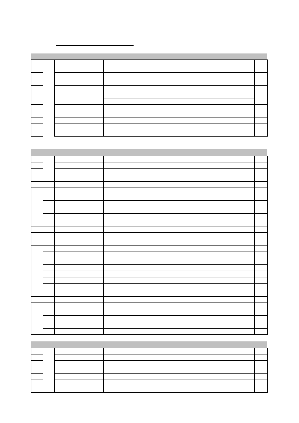
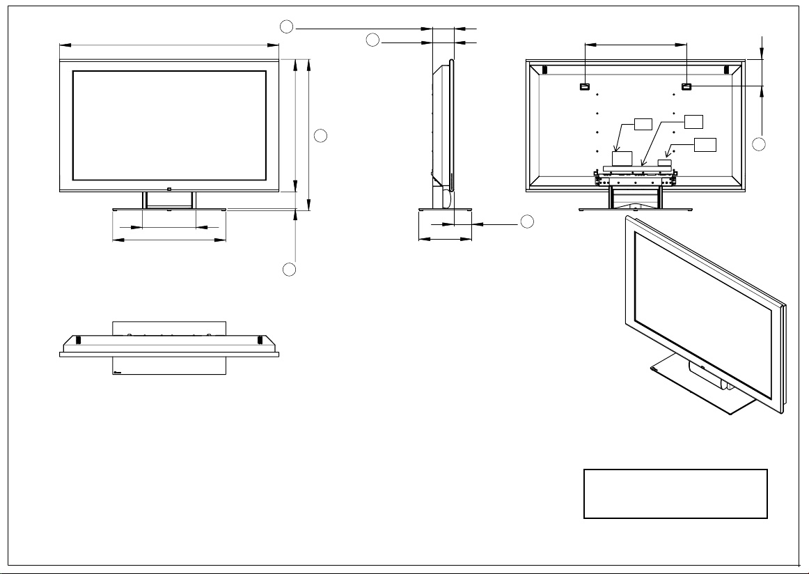
Dimension HT32
±1839
±2 (with wall mounting)
98,3
±296,3
540 ±2
284,2 ±2
600 ±1
±152589,5 ±2
10c
10a
10b
140,1 ±2
625,6 ±3
49,7 ±2
200
±1
European liaison office: 2, route de Tours, 72500 Château du Loir, France
tel: +33 (0)2 43 38 43 00 fax: +33 (0)2 43 44 93 83 www.harman.com
Harman Consumer Group International is a trading style o
JBL, Incorporated, 8500 Balboa Boulevard, Northridge, CA 91329, USA.
Page 8
±2 (with wall mounting)104,2
harman/kardon
HT 32" 40" 46"
European liaison office: 2, route de Tours, 72500 Château du Loir, France
tel: +33 (0)2 43 38 43 00 fax: +33 (0)2 43 44 93 83 www.harman.com
Harman Consumer Group International is a trading style of
JBL, Incorporated, 8500 Balboa Boulevard, Northridge, CA 91329, USA.
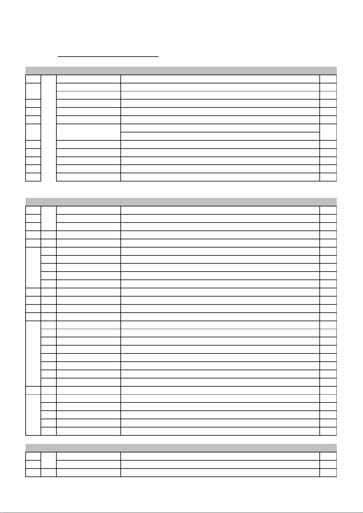
Dimension HT40"
10c
10a
10b
±11031
284,20 ±2
600 ±1
±1626,2089,50 ±2
726,80 ±3
102,2 ±2
540 ±2
140,2 ±2
±2103,8
±1280
Page 9
harman/kardon HT 32" 40" 46"
±11162
±2 (with wall mounting)113,2
111,2 ±2
540 ±2
284,20 ±2
600 ±1
±1702,2089,50 ±2
10c
802,8 ±3
10a
10b
139,8 ±2
01
±294,8
±1280
Dimensions HT 46"
European liaison office: 2, route de Tours, 72500 Château du Loir, France
tel: +33 (0)2 43 38 43 00 fax: +33 (0)2 43 44 93 83 www.harman.com
Harman Consumer Group International is a trading style of
JBL, Incorporated, 8500 Balboa Boulevard, Northridge, CA 91329, USA.
Page 10
±15
harman/kardon
HT 32" 40" 46"
European liaison office: 2, route de Tours, 72500 Château du Loir, France
tel: +33 (0)2 43 38 43 00 fax: +33 (0)2 43 44 93 83 www.harman.com
Harman Consumer Group International is a trading style of
JBL, Incorporated, 8500 Balboa Boulevard, Northridge, CA 91329, USA.
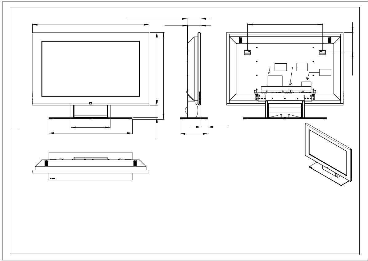
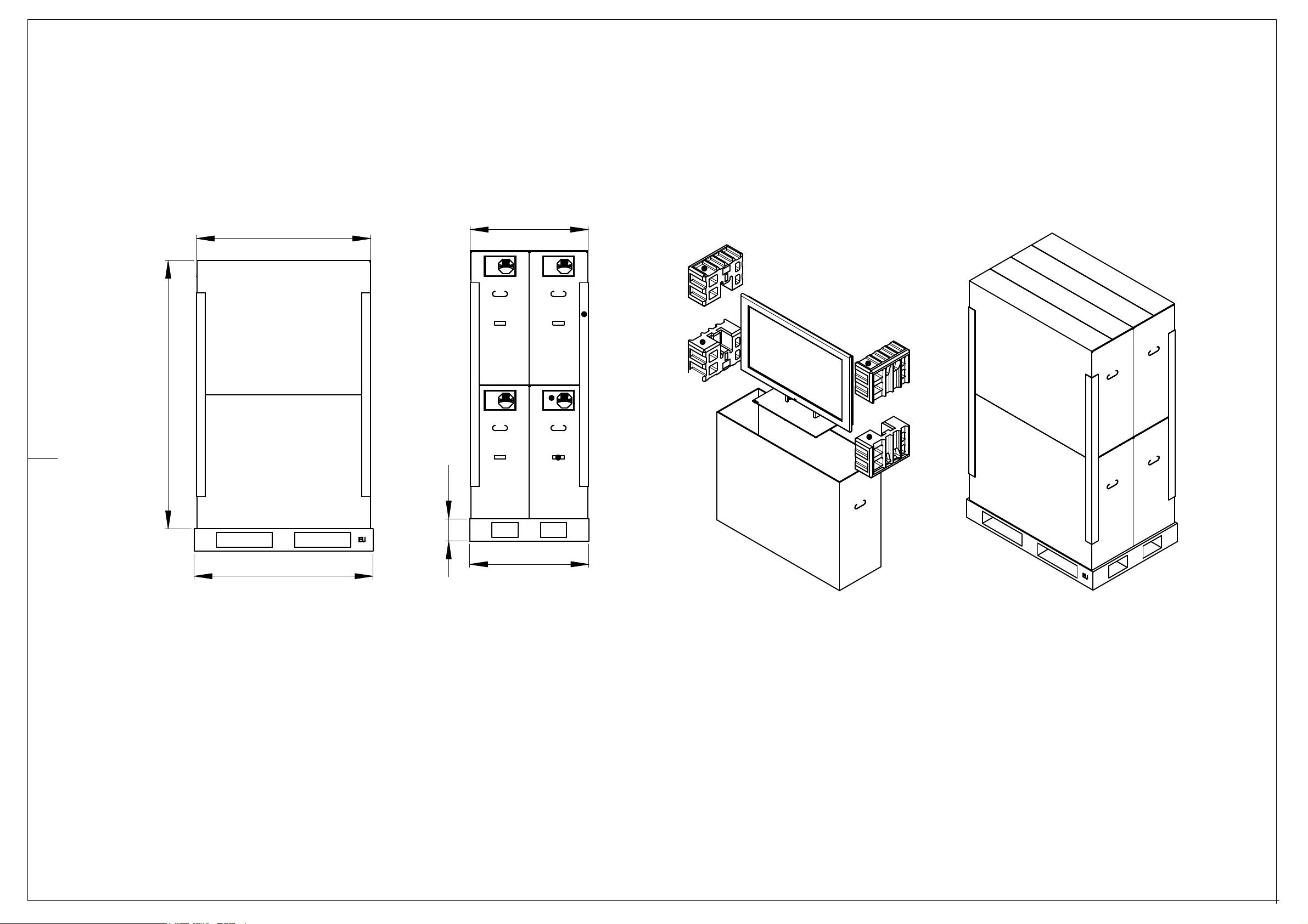
Dimension HT40"
1802,20
1169 ±15
±15792
150
1200
800
Page 11
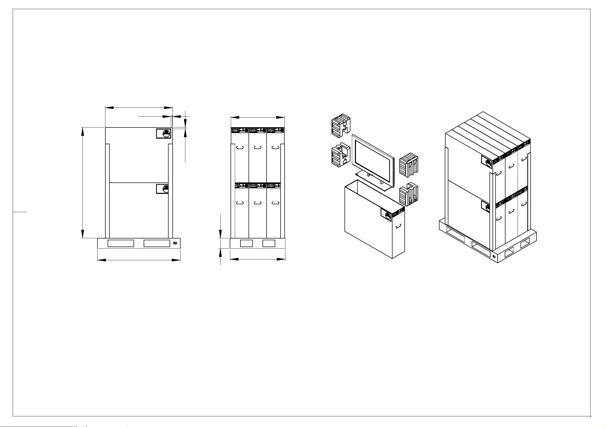
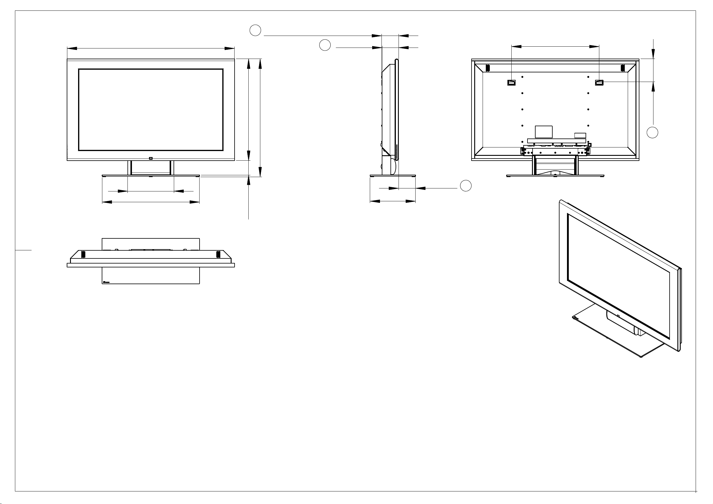
±151610
Dimensions HT32"
±15977
20
±10
±15780
20 ±10
150
1200
800
Page 12
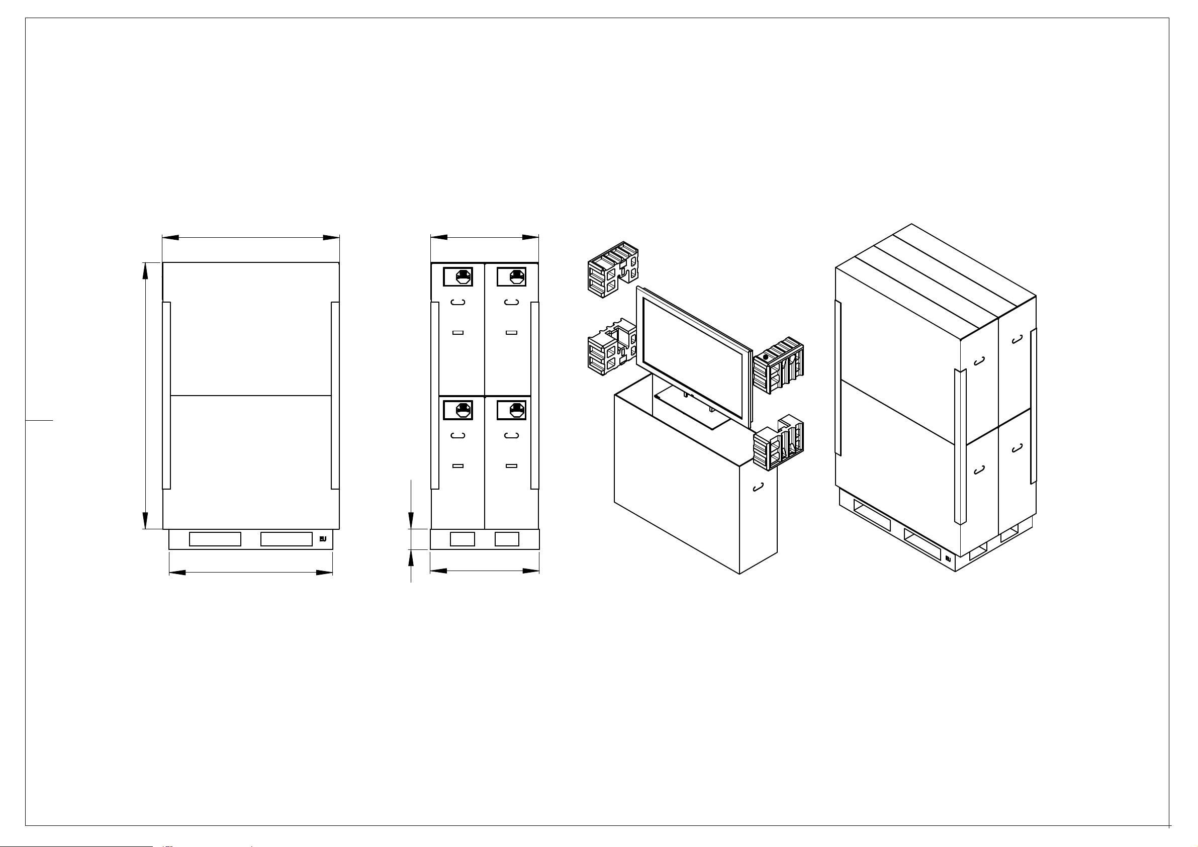
±15
Dimensions HT 46"
1954,20
1300 ±15
±15792
150
1200
800
Page 13
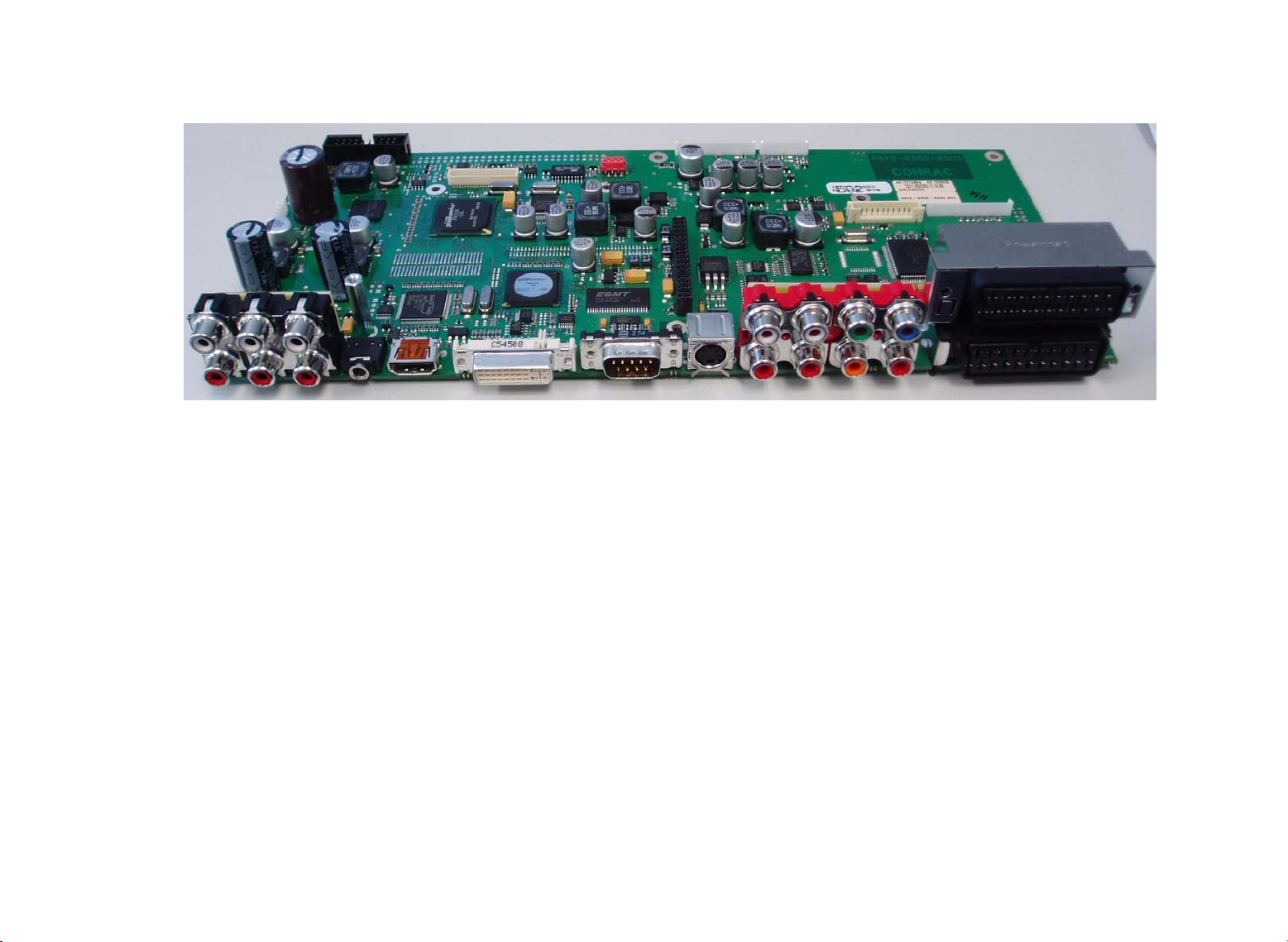
AV5 Main board
Special Features
- High End picture performance
- Manifold Inputs
- Usage of state-of-the-art Video-Processing-ICs
- Digital Audio In- and Output (SPDIF/PCM)
- HDMI-input (1080i max.)
- DVI with HDCP
- Video text, Level 1.5, memory 5000 pages min.
- 2 EURO AV SCART-connectors
- 5H- and 3D-comb filter
Page 14
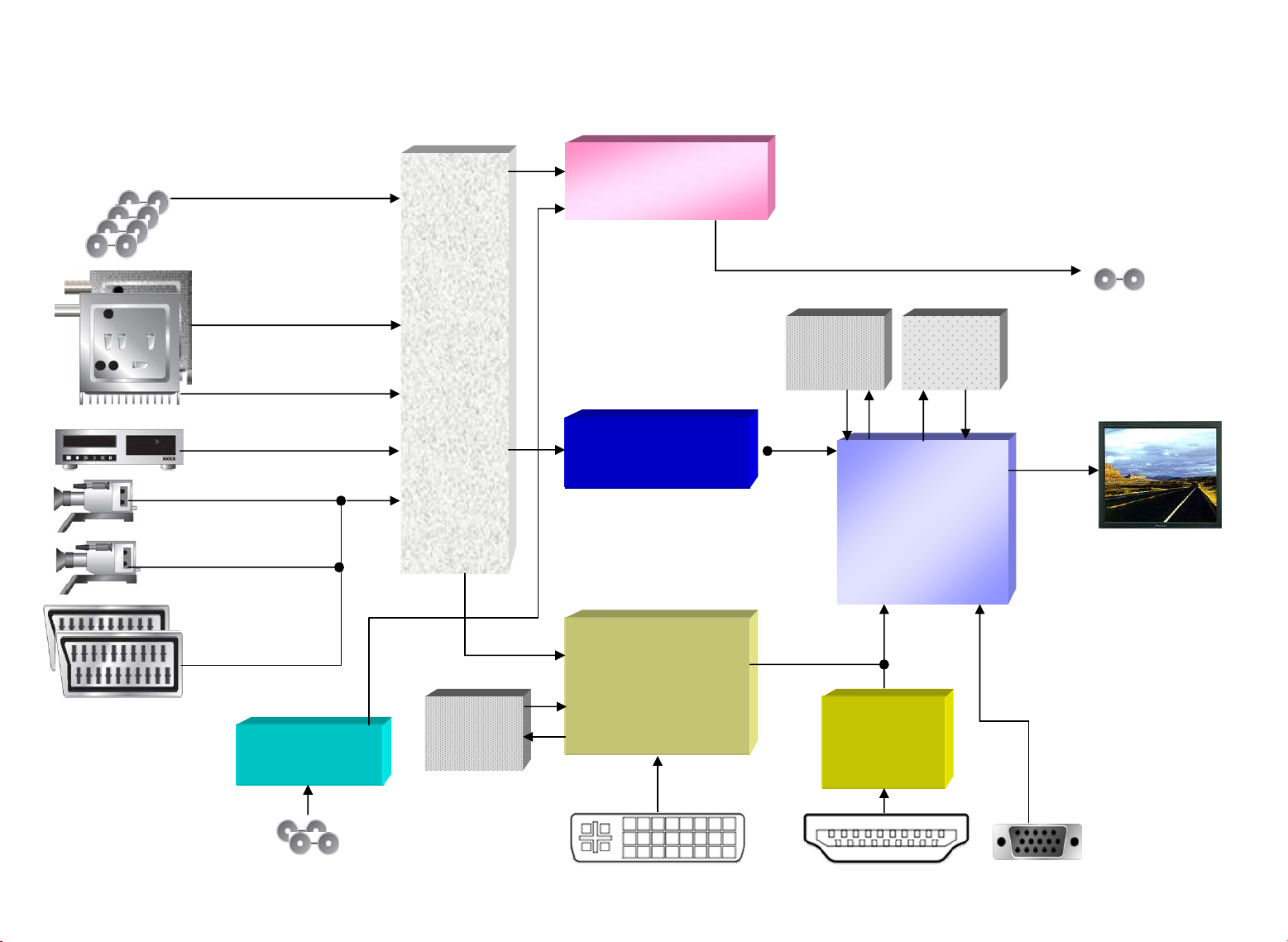
AV5 blockdiagram
Sound DSP
MSP 44x0K
3x Audio Line In
.
PIP Tuner
YUV (1080i)
Front- AV (inkl YC)
YC & CVBS
2x SCART In (1x
RGB, 1x YC)
Audio/
Video
Matrix-
Block
(1x TEA6422,
1x TEA6415,
1x TEA6425,
2x FMS6403)
SDRAM
1MByte
Video Decoder
VPX 3228F
Video Decoder,
ADC, DVI-Rx
PW3300B1
DDR
32MByte
HDMI Rx
SiI 9011
Flash
1MByte
Graphics
Engine
PW318C
1x SPDIF,
,
.
.
2x 10 Bit Dual
LVDS
16:9 Flat Panel
SPDIF In
RS232 ControlHDMI InDVI-I In
Page 15

AV5-connectors
to power supply
to tuner pcb
HT32 to backlight pcb
HT40/46 to power supply
to Panel
to front LED/IR
to power supply
(HT32 only)
288mm
130mm
Audio-Out
Speaker R/L
Dig / Sub-Out
K25
CN2
K12
K22
K5
K18
K11
Line Out R/L
K
6
Double-
Tuner
K15
K13 K1
K21
RF-InPIP-In RF-Out
K7
Audio-In
R/ L
S-Video
CVBS
YUV / CVBS
K19
AV2
UY
PC-Audio-IN
HDMI
DVI
RS232
S-Video
V
SPDIF-In
AV1
Page 16

DL HT32 - HT40 - HT46
Harman Consumer Group International
Introduction
1.1. Intention of the Design Requirements
The intention of this document is determination of the technical parameters, the electrical interfaces
and the mechanical size for the
Electronic.
1.2. Abbreviations
DVI Digital Visual Interface
HDCP High-bandwidth Digital Content Protection
HDMI High Definition Multimedia Interface
SDTV Standard-Definition Television
EDTV Enhanced-Definition Television
HDTV High-Definition Television
NTSC National Television Standards Committee
USB Universal Serial Bus
SPDIF Sony/Philips Digital Interface
FBAS Farb Bild Austast Synchronisation (english CVBS)
CVBS Composite Video Burst Sync (german FBAS)
DVB Digital Video Broadcast
RoHS Restriction for the use of Hazardous Substances
t.b.d. To Be Defined
2. Description of the Electronic
2.1. Functional Description
The Electronic is the interface between analogue/digital video-sources with different standards
In addition the audio input signals are processed.
Is supplied by an external SMPS.
The firmware-update is done by a serial port.
Page 17

DL HT32 - HT40 - HT46
Harman Consumer Group International
2.2. Technical Data
Supply voltages and supply current:
.
1 Stand-By-Voltage
(at K22-3)
2 Logic-Supply-Voltage
(at K22-5 and K22-7)
3 Tuner-Supply-Voltage
(at K22-9) with DualTuner-Module
4 Audio-Supply-Voltage
(at K22-1 and K22-2)
+12V- audio supply
.
.
.
Item Symbol Term/
Voltage +5V PD +4.75 +5.0 +5.25 V
Stability 0.1 – 1A
Ripple + Noise 100 mVpp
Current (RMS) 0.025 0.040 0.055 A
Current instant tbd A
Current inrush tbd A
Voltage +5V +4.75 +5.0 +5.25 V
Stability
Ripple + Noise 100 mVpp
Current (RMS)
No TFT-Load
EXTRA-Load for
TFT-Logic
Current instant tbd A
Current inrush tbd A
Voltage +12V +11.40 +12.0 +12.6 V
Stability 0.1 – 1A
Ripple + Noise 150 mVpp
Current (RMS) 0.74 0.75 0.76 A
Current instant tbd A
Current inrush tbd A
Voltage +V-audio +11.40 +12.0 +12.6 V
Stability
Ripple + Noise 0.01 – 1A 150 mVpp
Current (RMS)* 0.01 1.2 A
Current instant tbd A
Current inrush tbd A
Condition
1.25 1.30 A
TFT-Load up to 2.5A is acceptable (-> in total 3.8A)
Rating No
Min. Typ. Max.
±5.0
±5.0
±5.0
±5.0
Unit
%
%
%
%
Page 18

DL HT32 - HT40 - HT46
Harman Consumer Group International
2.3. Special Features
- High End picture performance
- Versatile Inputs
- Use of latest video-processing-ICs
- DVB capable (optional connector)
- digital audio-input and output (SPDIF)
- integrated audio delay line (up to 200ms per channel) to support lip-sync (optional)
- Digital audio amplifier (95% efficiency)
- HDMI-input (max. 1080i)
- DVI with HDCP
- Teletext, Level 1.5, min 5000 pages program memory
- 2 EURO AV SCART-connectors
- 5H- and 3D-comb-filter
Additional Highlights:
- YUV-Input :
o High Performance HDTV input (high quality motion adaptive deinterlacing) up to 1080i
o input for progressive analog video signals (EIA770.2)
o input resolution up to 1080i
- High performance PIP and multiple windows engine
o movable and scalable video/RGB window on RGB/Video or two separate non-
overlapping windows with independently scaled images
- High performance scaling engine:
o independent programmable input scalers for each input port providing advanced
scaler with adaptive algorithm for intelligent scaling, multiregion, non-linear scaling
o world class image scaler for video and VGA signals
- High performance de-interlacer:
o high performance motion adaptive de-interlacing (up to 1080i)
o high performance film mode treatment
o high performance low angle treatment for moving objects (incl. HDTV 1080i)
- High performance noise reduction:
o high performance noise reduction engine
o spatial and temporal motion adaptive noise reduction
o world class noise reduction
- Option slot for digital video sources:
o option slot is prepared for special add-on board for IEEE1394 (Fire Wire), DV (digital
camcorder), SDI, DVB-T, etc.
- High performance audio processing
o SPDIF input and output
o Delay line to ensure proper lip sync (optional)
o Virtual Dolby Digital processing (optional)
Page 19

DL HT32 - HT40 - HT46
Harman Consumer Group International
3.3. K22, Power supply
Type : B12B-EH-A from JST, No. 2170-0047-1121
Pin arrangement Pin Signal I/O Description
1
2
3
4
5
6
7
8
9
10
11
12
+12V/+24V
+12V/+24V
+5V-StdBy
GND
+5V
GND
+5V
GND
+12V
PSTDBY
PSDPMS
PSVRR
In
Audio-Supply: +12V/+24V (+/-10%, max. 1A)
In
Audio-Supply: +12V/+24V (+/-10%, max. 1A)
In
+5VSTBY (+/- 5%), present all the time (max. 1A)
In
+5V (+/- 5%) applied by PSU in normal mode
In
(same as no. 5, routed in parallel)
In
+12V (+/- 5%) applied by PSU in normal mode
Out
Out
0V -> PSU supplies +5V/+12V; 3.3V -> PSU
stops +5V/+12V
(0V/3.3V) Not used, for future purposes
In
0V -> PSU is working properly, 3.3V -> PSU
(max. 2A)
(max. 0.6A)
problem (diagnostic signal provided by the PSU)
3.4. K12, Audio-supply
Type : B4B-EH-A from JST, No. 2170-0047-1041
Pin arrangement Pin Signal I/O Description
1
2
3
4
GND
GND
+12V/+24V
+12V/+24V
In
In
Audio-Supply: +12V/+24V (+/-10%, max. 1A)
Audio-Supply: +12V/+24V (+/-10%, max. 1A)
Page 20

DL HT32 - HT40 - HT46
Harman Consumer Group International
3.5. K5, Backlight-supply
Type : B12B-PH-SM3-TB from JST, No. 2170-0122-1120
Pin arrangement Pin Signal I/O Description
1
2
3
4
5
6
7
8
9
10
11
12
BCKPWM
BCKPWM
GND
BCKLGHT
BCKLGHT
GND
BO1_5V
BO1_5V
PNLIO3
PNLIO4
N.C.
GND
Out
Out
Out
Out
Out
Out
Out
Out
Backlight PWM-Signal (5V level, alternatively
3.3V)
(same as no. 1, routed in parallel)
BL Analog-Signal (5V level, alternatively 3.3V)
(same as no. 4, routed in parallel)
BL On/Off-Signal (5V level, alternatively 3.3V)
(same as no. 7, routed in parallel)
General I/Os, 3.3V, 10mA
General I/Os, 3.3V, 10mA
Page 21

DL HT32 - HT40 - HT46
Harman Consumer Group International
3.7. K25, Keyboard-connector
Type: 20pin, double row, shrouded pin header, male, pitch 2.54, No. 2170-0043-1200
Pin arrangement Pin Signal I/O Description
1
19
2
20
1
2
3
4
5
6
7
8
9
10
11
12
13
14
15
16
17
18
19
20
GND
NC
Red LED
Green LED
N.C.
N.C.
GND
N.C.
ALC +
N.C.
GND
GND
T5
T4
T3
T2
T1
GND
+5VST
IRR
Out
Out
In
In
In
In
In
In
Out
In
+5V, 10mA, high active
+5V, 10mA, high active
analog Input, 0V..+5V
key5, low active, +5VST
key4, low active, +5VST
key3, low active, +5VST
key2, low active, +5VST
key1, low active, +5VST
50mA for keyboard
IR-input (from TSOP 1238, 5V level)
3.8. K1, RS232-interface, serial interface for firmware-update,
Type: 9pin, double row, D-Sub, male, No. 2170-0218-2091
Pin arrangement Pin Signal I/O Description
Front view
1
2
3
4
5
6
7
8
9
N.C.
Rx
Tx
In
Out
Receive Data (+/-12V)
Transmit Data (+/-12V)
N.C.
GND
N.C.
N.C.
N.C.
N.C.
Page 22

DL HT32 - HT40 - HT46
Harman Consumer Group International
3.9. K21, YC-connector,
Type: Mini-Din-socket MD-146D-4P with GND-clips, No. 2175-0129-3040
Pin arrangement Pin Signal I/O Description
Front view
3.10. K13, DVI-connector
Type: DVI-socket, Molex-reference-No. 74320-1004, No. 2172-0213-0290
Pin arrangement Pin Signal I/O Description
Front view
1
2
3
4
Ground
Ground
Y
C
1
2
3
TX2/4-SHLD
4
5
6
7
DDC-CLK
DDC-Data
8
9
10
11
TX1/3-SHLD
12
13
14
15
16
Ground (for +5V)
HP Detect
17
18
19
TX0/5-SHLD
20
21
22
TXC-SHLD
23
24
C1
C2
C3
C4
C5
Analog RGB Ground
DT2-
DT2+
N.C.
N.C.
AVS
DT1-
DT1+
N.C.
N.C.
+5V
DT0-
DT0+
N.C.
N.C.
CLK+
CLK-
ARED
AGRN
ABLU
AHS
In
In
Luminance
Chrominance
In
In
In
I/O
In
In
In
In
Out
In
In
In
In
In
In
In
In
TMDS Data2-
TMDS Data2+
TMDS Data2 Shield
I2C-Clock, +5V level
I2C-Data, +5V level
Analog Vertical Sync
TMDS Data1-
TMDS Data1+
TMDS Data1 Shield
+5V Power*
Hot Plug Detect
TMDS Data0-
TMDS Data0+
TMDS Data0 Shield
TMDS Clock Shield
TMDS Clock +
TMDS Clock –
Analog Red
Analog Green
Analog Blue
Analog Horizontal Sync
Page 23

DL HT32 - HT40 - HT46
Harman Consumer Group International
3.12. K19-A, (lower SCART-socket: AV1, RGB & CVBS)
Type : 2202-21ST(A) from POWERNET, No. 2172-0302-6200
Pin arrangement Pin Signal Pin Signal
1
2
3
4
AV1
5
6
7
8
9
10
11
Audio-out, right
Audio-in, right
Audio-out, left
Widescreen-s. (CVBS)
SCLSC5V-AV2
Green video in
GND
GND
Audio-in, left
Blue video in
GND
12
13
14
15
16
17
18
19
20
21
SDASC5V-AV2
GND
GND
Red video in
RGB-status-signal (FB)
GND
GND
CVBS2 output, RGB-Sync
CVBS2 input, RGB-Sync
Shielding / GND
Pin 8/14 : Widescreen-Signaling / corresponding GND
+6V : input signal is 16:9-format
+12V : input signal is 4:3 letterbox-format
Pin 16/18 : RGB-status-signal / corresponding GND
High : input signal is RGB
Low : input signal is CVBS
3.13. K19-B, (upper SCART-socket.: AV2, YC & CVBS)
Type : 2202-21ST(A) von POWERNET, No. 2172-0302-6200
Pin arrangement Pin Signal Pin Signal
AV2
1
2
3
4
5
6
7
8
9
10
11
Audio1-out, right
Audio1-in, right
Audio1-out, left
Audio-GND
Audio1-in, left
Widescreen-s. (CVBS)
SCLSC5V-AV1
GND
N.C.
GND
N.C.
12
13
14
15
16
17
18
19
20
21
SDASC5V-AV1
GND
GND
Y/C : C-in
N.C:
GND
GND
CVBS1-out (Y/C)
CVBS1-, Y1 – in (Y/C)
Shielding / GND
Page 24

DL HT32 - HT40 - HT46
Harman Consumer Group International
3.14. K7, YUV-, SPDIF-, audio- input-connector,
Type: RCA-Jack, RS853A8-V-01 . 2175-0130-0080
Pin arrangement Pin Signal I/O Description
Front view
A-pin
A-shield
B-pin
B-shield
A1-pin
A1-shield
B1-pin
B1-shield
C-pin
C-shield
D-pin
D-shield
C1-pin
C1-shield
D1-pin
D1-shield
YUV/CVBS-aud.-R
YUV/CVBS-Aud.-L
Y/C-aud.-R
GND
GND
Y/C-Aud.-L
GND
GND
SPDIF-In
GND
V-In
GND
CVBS / Y-In
GND
U-In
GND
In
In
In
In
In
In
In
In
Red
Red
White
White
Orange
Red
Green
Blue
3.15. K11, audio-out-connector
Type: RCA-Jack, RS621-V-01 No. 2175-0131-0060
Pin arrangement Pin Signal I/O Description
Front view
A-pin
A-shield
B-pin
B-shield
C-pin
C-shield
A1-pin
A1-shield
B1-pin
B1-shield
C1-pin
C1-shield
Speaker-Out-R
GND
SPDIF-OUT
GND
Line-Out-R
GND
Speaker-Out-L
GND
Subwoofer-Line-Out
GND
Line-Out-L
GND
Out
Out
Out
Out
Out
Out
Red
Red
Red
White
White
White
Page 25

DL HT32 - HT40 - HT46
Harman Consumer Group International
3.18. K15, HDMI-connector
Type: 19pin, double row, Molex-reference-No. 500254-1927,No. 2171-0576-2190
Pin arrangement Pin Signal I/O Description
Front view
No additional audio line-input for HDMI
Note:
1
2
3
4
5
6
7
8
9
10
11
12
13
14
15
16
17
18
19
R1X2+
GND
R1X2-
R1X1+
GND
R1X1-
R1X0+
GND
R1X0-
R1XC+
GND
R1XC-
NC
NC
DSCL
DSDA
GND
HDMIHOT
HOTPLUG
In
In
In
In
In
In
In
In
In
I/O
In
Out
Data-Clock
Data-Clock
I2C-Data, +5V level
I2C-Clock, +5V level
+5V Power
Hot Plug Detect Signal
Data
Data
Data
Data
Data
Data
3.19. K18, Tuner-connector
Type: 36pin socket terminal, double row, RM2,54, BL2-36Z, No. 2171-0044-1360
Pin arrangement Pin Signal I/O Description
1
2
3
4
5
6
7
8
9
10
11
12
13
14
15
16
17
18
19
GND
+5V
GND
+5V
GND
+5V
GND
N.C.
GND
N.C.
GND
+9V
GND
+9V
GND
+12V
GND
SSIF2
GND
Out
Out
Out
Out
Out
Out
In
+5V (+/-5%)
+5V (+/-5%)
+5V (+/-5%)
+9V (+/-5%)
+9V (+/-5%)
+12V (+/-5%)
Digital Sound IF2
Page 26

DL HT32 - HT40 - HT46
Harman Consumer Group International
20
1
3
5
31
33
35
2
4
6
32
34
36
21
22
23
24
25
26
27
28
29
30
31
32
33
34
35
36
CVBST2
GND
SW22K5V
GND
TUNMONO
GND
SCL5V
GND
SCL5V
GND
SDA5V
GND
TUNMONO
GND
CVBST1
GND
SSIF1
In
Out
In
Out
Out
In
In
In
In
CVBS Tuner 2
I2C-Clock, 5V level
I2C-Clock, 5V level
I2C-Data, 5V level
CVBS Tuner 1
Digital Sound IF1
Page 27

DL HT32 - HT40 - HT46
Harman Consumer Group International
3.22. CN2, LVDS-output
Type: DF20G-50DP-1 from Hirose, No. 2170-0611-2500
Pin arrangement Pin Signal I/O Description
1
2
3
4
5
6
7
8
9
10
11
12
13
14
15
16
17
18
19
20
21
22
23
24
25
26
27
28
29
30
31
32
33
34
35
36
37
38
39
40
41
42
43
44
45
46
47
48
49
50
FPPAR
FPCTRL
RxO0-
RxE0-
RxO0+
RxE0+
GND
GND
RxO1-
RxE1-
RxO1+
RxE1+
GND
GND
RxO2-
RxE2-
RxO2+
RxE2+
GND
GND
RxOC-
RxEC-
RxOC+
RxEC+
GND
GND
RxO3-
RxE3-
RxO3+
RxE3+
GND
GND
RxO4-
RxE4-
RxO4+
RxE4+
LO1_5V
LIO4
LIO3
SDA
+5VPNL
SCL
+5VPNL
+12VPNL
+5VPNL
+12VPNL
+5VPNL
+12VPNL
+5VPNL
+12VPNL
Out
Out
Out
Out
Out
Out
Out
Out
Out
Out
Out
Out
Out
Out
Out
Out
Out
Out
Out
Out
Out
Out
Out
Out
Out
Out
Out
Out
I/O
I/O
Out
Out
Out
Out
Out
Out
Out
Out
Out
Out
Out
digital I/O with +3.3V level, out max. 10mA
digital I/O with +3.3V level, out max. 10mA
Data
Data
Data
Data
Data
Data
Data
Data
Data
Data
Data
Data
Data-Clock
Data-Clock
Data-Clock
Data-Clock
Data
Data
Data
Data
Data
Data
Data
Data
digital output with TTL +5V level
digital I/O with +3.3V level, out max. 10mA
digital I/O with +3.3V level, out max. 10mA
I2C-Data, +3.3V level
+5V (+/-5%, all +5V pins max. 2A)
I2C-Clock, +3.3V level
+5V
+12V (+/-5%, all +12V pins max. 1.5A)
+5V
+12V
+5V
+12V
+5V
+12V
Page 28

DL HT32 - HT40 - HT46
Harman Consumer Group International
1
3
5
75
77
79
It is also possible to mount on K17 only a 50pin connector (Pin1-Pin50) e.g. for use with
Note:
DVB-module
2
4
6
76
78
80
33
34
35
36
37
38
39
40
41
42
43
44
45
46
47
48
49
50
51
52
53
54
55
56
57
58
59
60
61
62
63
64
65
66
67
68
69
70
71
72
73
74
75
76
77
78
79
80
GND
GND
PORT1Y7
PORT1Y6
PORT1Y5
PORT1Y4
PORT1Y3
PORT1Y2
PORT1Y1
PORT1Y0
GND
GND
DVBIO1
DVBIO3
DVBIO2
IN0CLK
GND
GND
IN0BE9
IN0BE8
IN0BE7
IN0BE6
IN0BE5
IN0BE4
IN0BE3
IN0BE2
IN0GE9
IN0GE8
IN0GE7
IN0GE6
IN0GE5
IN0GE4
IN0GE3
IN0GE2
IN0RE9
IN0RE8
IN0RE7
IN0RE6
IN0RE5
IN0RE4
IN0RE3
IN0RE2
GND
GND
IN0HS
IN0VS
IN0VBI
IN1VBI
ITU-656IN7
ITU-656IN6
ITU-656IN5
ITU-656IN4
ITU-656IN3
ITU-656IN2
ITU-656IN1
ITU-656IN0
GPIO +3.3V ; 10mA
GPIO +3.3V ; 10mA
GPIO +3.3V ; 10mA
Data0 Clock
Data0 Blue Bit9
Data0 Blue Bit8
Data0 Blue Bit7
Data0 Blue Bit6
Data0 Blue Bit5
Data0 Blue Bit4
Data0 Blue Bit3
Data0 Blue Bit2
Data0 Green Bit9
Data0 Green Bit8
Data0 Green Bit7
Data0 Green Bit6
Data0 Green Bit5
Data0 Green Bit4
Data0 Green Bit3
Data0 Green Bit2
Data0 Red Bit9
Data0 Red Bit8
Data0 Red Bit7
Data0 Red Bit6
Data0 Red Bit5
Data0 Red Bit4
Data0 Red Bit3
Data0 Red Bit2
Horizontal Sync0
Vertical Sync0
Vertical Blanking Interval 0
Vertical Blanking Interval 1
Page 29

DL HT32 - HT40 - HT46
Harman Consumer Group International
3.25. CN---, IEC-antenna-connector on separate Tuner-module
Pin arrangement Pin Signal
Front view
Pin
shield
RF-In
GND
3.26. CN---, IEC-antenna-connector
Pin arrangement Pin Signal
IN OUT
Front view
pin
shield
pin
shield
RF-In
GND
RF-Out
GND
separate Tuner-module
Page 30

DL HT32 - HT40 - HT46
Harman Consumer Group International
4.2. Possible in- and output-signals
Interface Connector / Nr. Input Output
Tuner
AV1 / AV2
YUV / CVBS
S-Video
DVI / VGA
HDMI
Front socket
Audio in
(analogue)
Audio in (digital)
Audio out
(analogue)
IEC s. separate Tuner-module
SCART CVBS,
RGB (FB) or YC
AUDIO
CVBS,
AUDIO
3x RCA
Component YCrCb
(SDTV, EDTV, HDTV)
---
4pin Mini Din YC
DVI-I-socket RGB at 75 Ohm, H / V TTL
TMDS DVI 1.0
HDMI plug digital video/audio
2x RCA
Mini DIN
RCA
AUDIO
YC
CVBS
Headphone
2x2 RCA l/r
3.5mm stereo jack
Audio from YC
Audio from YUV / CVBS
Audio from PC
1x RCA SPDIF
2x RCA l/r
AUDIO-Line-out
1x RCA Subwoofer
Audio out
1x RCA SPDIF
(digital)
Service plug
9pin DSUB, male 1 x RS232, Rx 1 x RS232, Tx
Page 31

DL HT32 - HT40 - HT46
Harman Consumer Group International
4.2.1 PC analog input
- RGB-input
• Signal level:
• Polarity:
• Impedance:
• Video Bandwidth
• Rise/Fall time:
• Jitter:
• Syncronization
0 - 700mV, tolerance ± 10%
positive
75 Ohm
≤ 110 MHz
≤ 3.7 ns
≤ 1.1 ns
H/V separate sync: TTL
H/V composite sync: TTL
Sync on green
The video interface must be capable to display video content with high change rate (e.g. pixel patch
pattern one pixel on, one pixel off) without distortion of the image. The display quality must be
maintained over the specified temperature range.
- TTL-inputs (Sync-Signals)
The Monitor has to operate up to the following specified TTL-input signals:
• Level:
L = 0V – 0.8V H = 2.0V - 5V
• Polarity:
H- Sync. and V - Sync. signals at the monitor input
• High logic level:
• Rise time:
• Pos. overshoot:
< 0.7V
2.0V
0.8V
0V
< 50 ns
≥ 2.0 V
0.8 V - 2.0 V: < 50 ns
< 0.7 V
positive or negative
< 200 ns
< 50 ns
• Low logic level:
• Fall time:
• Neg. overshoot:
2.0V
0.8V
< 0.7V
< 200 ns
≤ 0.8 V
2.0 V - 0.8 V: < 50 ns
< - 0.7 V
Page 32

DL HT32 - HT40 - HT46
Harman Consumer Group International
Characteristics of the monitor input circuit
• Threshold voltage:
1.2 V - 1.5 V typ.
• High level noise margin:
• Low level noise margin:
• Impedance:
0.5 V typ., 0.3 V min.
0.4 V typ., 0.2 V min.
≥ 2.2 kΩ
- Noise immunity:
The inputs shall have a hysteresis of 0.4 V min., (0.8 V typ).
Without hysteresis the following condition has to be met:
If there is a second transition of a sync. signal through the threshold region within 100 ns after a trigger
event, it may not cause any malfunction of the monitor.
- DDC-Signals on DVI connector:
• DDC Serial Data:
• DDC Serial Clock:
Pin 7, I
Pin 6, I
2
C-BUS
2
C-BUS
4.2.2 Digital input HDMI and DVI-I
• Signal format:
Panel Link
TM
TMDS
(Transmission Minimized Differential Signalling)
• R/G/B color depth:
• Dot clock rate:
• Signals:
8 bit
110 MHz max. (Single Link)
1 channel TMDS
- TMDS data: TX0+/-, TX1+/-, TX2+/-
- TMDS clock: TXC+/-
- not used: TX3+/-, TX4+/-, TX5+/-
• DDC:
SDA, SCK : I
2
C-BUS
The HDMI and DVI-D input is equipped with HDCP
- Video Blanking
The video will be blanked for a period of 1 s to 2 s during change of modes or if undefined signals are
applied. No switching effects are visible!
- DDC Signals on DVI connector see above
- DDC Signals on HDMI connector:
• DDC Serial Data:
• DDC Serial Clock:
Pin 16, I
Pin 15, I
2
C-BUS
2
C-BUS
Page 33

DL HT32 - HT40 - HT46
Harman Consumer Group International
The monitor has installed 4.7 kΩ pull-up on the SCL-line and a 4.7KΩ pullup resistor on the SDA and
SCL line. The DDC EEPROM’s are connected to monitor Vcc and to DDC +5V as well, that the
system can read the DDC Information also when the Monitor is powered off.
The graphic controller board should provide pull-up resistors of ≥ 1.5 kΩ and ≤ 2.2 kΩ to a +5V
reference or a 3 mA current source for the SCL and SDA open drain signals.
• High logic input level:
• Low logic input level :
≥ 2.8 V (3.0 V)
≤ 0.8 V (1.5 V)
• Low logic output level :
≤ 0.4 V
4.2.3 RF-input
Minimum input level: 50 dBµV @ 75 Ohm
Video standards PAL 4.43 50Hz B/G, D/K, I, L, L1
PAL 4.43 60Hz B/G, I
NTSC 3.58 60Hz M not for tuner-module
NTSC 4.4 60Hz B/G not for tuner-module
SECAM 50Hz B/G, D/K, L, L1
HDTV: 480i, 480p, 576p, 720p, 1080i (1080p optional)
Signals CVBS
Y / C
RGB with additional sync (fast blank possible)
YUV / YCrCb (component)
Audio standards FM-mono B/G, D/K, I, M, N
FM-stereo B/G, D/K, I
FM-bilingual B/G, D/K, I
NICAM-stereo B/G, D/K, I, L
NICAM-bilingual B/G, D/K, I, L
AM-Mono L
SPDIF input Cinch
Options Virtual Dolby®
4.2.4 Video-input
Item Conditions
Y 75 Ohm 1000 mVp-p
Component Input level Pb 75 Ohm 700 mVp-p
Pr 75 Ohm 700 mVp-p
R 75 Ohm 600 700 800 mVp-p
Input level G 75 Ohm 600 700 800 mVp-p
SCART B 75 Ohm 600 700 800 mVp-p
Comp. 75 Ohm 1000 mVp-p
output level Comp. 75 Ohm 1000 mVp-p
S-Video in Input level Y 75 Ohm 1000 mVp-p
C 75 Ohm 300 mVp-p
Composite Input level 75 Ohm 1000 mVp-p
Min Typ Max Unit
Specification
Page 34

d
d
DL HT32 - HT40 - HT46
Harman Consumer Group International
Corresponding Audio-input and output:
Audio in Input level 10 kOhm load 0.5 Vrms
Line output (variable) 10KOhm load 0.5 Vrms
Audio out SCART output 10KOhm load 500 mVrms
Sub woofer output 10KOhm load 250 mVrms
Output level THD 10%
Distortion [1W, 1kHz] TV 1 %
Speaker Other source 0,5 %
output S/N ratio TV TBD dB
Other source TBD dB
TV stereo separation -30dBm, 1kHz TBD dB
TV L,R balance TBD dB
4.2.5 S/PDIF
- S/PDIF IN (Coax)
Signal level: 5V TTL (max. 48KHz), Impedance: 75Ohm (typical)
Connector Type: RCA (orange)
- S/PDIF Out (Coax)
Signal level: 5V TTL (48KHz), Impedance: 75Ohm (typical)
Connector Type: RCA (red)
4.2.6 SCART-Input
Pin Signal Signal level
1 Audio R out 0.5 Vrms 1) 10kOhm loa
2 Audio R in 0.5 Vrms (>= 0.2 Vrms) 1) 15 kOhm
3 Audio L out 0.5 Vrms 1) 10kOhm loa
4 GND Audio
5 GND blue
6 Audio L in 0.5 Vrms (>= 0.2 Vrms) 1) 15 kOhm
7 Blue video 0.7 V (+/- 0.1V) 2) 75 Ohm
8 Switch signal in TV mode: 0 .. 2 V
9 GND green
10 N/C
11 Green video 0.7 V (+/- 0.1V) 2) 75 Ohm
12 N/C
13 GND red
14 GND fast switch
15 Red video/ C
Video
16 Fast switch CVBS: 0 .. 0.4 V
17 GND video out
18 GND video in
19 Video out 3) 1.0 Vss +/- 3dB 75 Ohm
20 Video in 1.0 Vss +/- 3 dB / 75 Ohm
5+5,
PDP
7 +7
Min Typ Max
10 kOhm
AV Wide: 4.5 .. 7 V
AV 4:3: 9.5 .. 12 V
0.7 V (+/- 0.1V) / 0.3V (+/- 0.1V)
2)
RGB: 1.0 .. 3 V
load
75 Ohm
75 Ohm
W
Impedance
Page 35

DL HT32 - HT40 - HT46
Harman Consumer Group International
4.3. Timing Overview
4.3.1 Preset Timing Chart
A
B
Item Description:
A Total time
B Active display area
F Blanking time
G Front porch
H Sync-width
I Back porch
4.3.2 Timing Restrictions
Based on the following conditions the monitor is full-scan capable, the adjustment ranges for picturesize and -position are within specification.
Item Horizontal Vertical
Frequency 1/A 31 kHz - 70 kHz 50 Hz - 90 Hz
Blanking period F
Front porch period G
Sync. Period H
Back porch period I
Blank/Total F/A 29 % max. 26 % max.
Backporch - Frontporch x 100
2 x Total
Detectable mode
frequency separation
F
GH
I
(I -G) x 100
2 x A
(Video)
(Sync.)
2.430 µs min. 525 µs min.
0.188 µs min. 11 µs min.
0.987 µs - 4.0 µs 32 µs - 332 us
0.730 µs min. 427 µs min.
1 – 6.6 1 - 6.6
± 2.0 kHz min. ± 1.5 Hz min.
Page 36

DL HT32 - HT40 - HT46
Harman Consumer Group International
4.3.3 Factory Presetted and Predefined Timings
No Resolution
V-Freq
[Hz]
H-Freq
[kHz]
Pixel
Rate
[MHz]
HS-
pol
VS-
pol
Remark
1 640x480 59.94 31.47 25.175 N N VESA
2 72.81 37.86 31.500 N N VESA
3 75.00 37.50 31.500 N N VESA
4 800x600 56.25 35.156 36.000 P P VESA
5 60.32 37.879 40.000 P P VESA
6 72.2 48.077 50.000 P P VESA
7 75.0 46.875 49.500 P P VESA
8 1024x768 60.0 48.363 65.000 N N VESA
9 70.1 56.476 75.000 N N VESA
10 75.0 60.023 78.750 P P VESA
11 1280x720p 50 37.500 74.250 P P PC mode w/o overscan
12 50 37.500 74.250 P P
HDTV: Component, DVI
13 60 45.150 74.250 P P PC mode w/o overscan
14 60 45.150 74.250 P P
HDTV: Component, DVI
15 1280x1024 60.0 64.000 108.000 P P VESA
16 1360x768 60.0 47.700 85.500 P P VESA, no scaling
17 720x400 70.0 31.460 28.320 N P DOS
18 720x 480i 60.0 All inputs (not DVI-A)
19 720x 576i 50.0 All inputs (not DVI-A)
20 720x480p 60 31.469 27.000
21 720x576p 50 31.250 27.000
22 1920x1080i 50 33.780 74.250
23 60 33.780 74.250
HDTV: Component, DVI, HDMI
HDTV: Component, DVI; HDMI
HDTV: Component, DVI, HDMI
HDTV: Component, DVI, HDMI
PC Modes details for LCD panel resolution
No Resolution Fv
Hz
Fh
kHz
Fpix
MHz
HS VS H.tot
px
H.fp
px
HS.pw
px
V.tot
lines
V.fp
lines
VS.pw
**)
1360x768 50 39.76 71.25 P P 1792 64 112 795 3 6
1360x768 60 47.71 85,50 P P 1792 64 112 795 3 6
**) Fpix +/- 0.5%
lines
Page 37

DL HT32 - HT40 - HT46
Harman Consumer Group International
4.3.4 Digital Control Operation
Signals used for mode
detection:
• Nominal horizontal frequency
• Nominal vertical frequency
• Horizontal Sync. Pulse Polarity
• Vertical Sync. Pulse Polarity
• Amount of total lines
The tolerance for detecting the horizontal frequency is between ± 2% from the horizontal center
frequency.
The tolerance for detecting the vertical frequency is between ± 2% from the vertical center frequency.
PICTURE STABILITY: Picture position, size and image lock has to be stable even during warm up,
this means phase shift ≤ 2ns
PROTECTION CIRCUIT: Missing or improper sync pulses will not damage the monitor. Additionally,
under these conditions, the monitor shall not cause damage to the driving source.
4.4. Audio Electrical Performance
LOUDSPEAKER
Rated input 7W (2 speakers in parallel)
Max. input 10W (2 speakers in parallel)
Impedance
Resonant frequency
Frequency range 150 Hz – 20 kHz +/- 3 dB
AMPLIFIER
Max. Output 7W (PDP), 5W (TFT) per channel
Frequency range 100 Hz – 15 kHz
SUB WOOFER :
The sub woofer output is a "line" output and volume control works together with the built in speaker.
8 Ohm ± 15% (PDP), 2 Ohm ± 15% (TFT)
100 Hz ± 20%
Page 38

DL HT32 - HT40 - HT46
Harman Consumer Group International
4.5.2 On Screen Display (OSD)
PICTURE
DISPLAY
SOUND
VOLUME
BALANCE
EQIUALIZER
MODUS
VOLUME LINE OUT
MAX STARUP VOLUME
AVC
SPDIF INPUT
USER EQUALIZER
SETUP @ selected input:
TUNER
TUNER INPUTS INPUTS PC
OSD OSD OSD OSD OSD
INFO INFO INFO INFO INFO
SETUP\TUNER
AUTO SEARCH
MANUAL SEARCH
EDIT STATION LIST
SETUP\SCART1
TV SCART OFF/ON
RGB IN SCART/UNUSED/ALWAYS
FILM MODE ON/OFF
FORMAT DETECTION VOLTAGE/SOFTWARE
16:9 FORMAT LETTERBOX / ANAMORPH
SETUP\SCART2
TV SCART ON/OFF
YC IN UNUSED/ALWAYS
FILM MODE ON/OFF
FORMAT DETECTION VOLTAGE/SOFTWARE
16:9 FORMAT LETTERBOX / ANAMORPH
SETUP\CVBS
FILM MODE ON/OFF
SETUP\YC
FILM MODE ON/OFF
SETUP\YUV
FILM MODE ON/OFF
SETUP\HDMI
FILM MODE ON/OFF
(SETUP\PC DVI)
Item Options
SCART1,2
CVBS YC YUV
(NO SETUP SELECTIONS)
HDMI PC(DVI) PC(RGB)
Page 39

DL HT32 - HT40 - HT46
Harman Consumer Group International
SETUP\PC RGB
H FREQ
V FREQ
AUTO SETUP
H TOTAL
V POS
V SIZE
H POS
H SIZE
PHASE
SETUP\TUNER\AUTO SEARCH
COUNTRY
(VGA)
UK, France, Germany, Italy, Spain, Austria, Switzerland, Belgium,
Netherlands, Luxembourg, Denmark, Sweden, Finland, Norway,
Eire, Turkey
SEARCH FROM ALL CHANNELS / NEW CHANNELS
START SEARCH
SETUP\TUNER\MANUAL
SEARCH
PROGRAMME PROGRAMME NUMBER FROM 0 TO 99
TYPE CHANNEL / SPECIAL CHANNEL
CHANNEL ENTER A CHANNEL NUMBER or
FREQUENCY 5 DIGIT FREQUENCY
NAME
TV STANDARD
COLOUR STANDARD PAL/SECAM
DECODER
FOR PAL: B/G D/K I
FOR SECAM: B/G D/K L
SETUP\EDIT STATION LIST
SETUP\OSD
TIME OUT OFF 5 10 15 20 25 or 30 sec.
TRANSPARANCY 1 - 10
SHOW LOGO ON/OFF
RESET TO FACTORY
´ DEFAULTS
LANGUAGE
TTX SETUP WEST EAST RUSSIAN ARABIC
YELLOW BUTTON: SELECT THE CHANNEL TO BE SHIFTED
GREEN BUTTON: SELECT A CHANNEL TO BE DELETED
RED BUTTON: CLOSE EDIT MENU
English, Francáis, Deutsch, Italiano, Espanol, Portugues,
Nederlands, Svenska, Noersk, Suomi,
Dansk, Polski
Page 40

DL HT32 - HT40 - HT46
Harman Consumer Group International
After switching on the TV the first time the language and the country has to be selected. After that the
automatic station search starts.
Lanuguage settings for OSD:
English, Francáis, Deutsch, Italiano, Espanol, Portugues, Nederlands, Svenska, Noersk, Suomi,
Dansk, Polski
Selection of the country for the TV channel sorting sequence:
UK, France, Germany, Italy, Spain, Austria, Switzerland, Belgium, Netherlands, Luxembourg,
Denmark, Sweden, Finland, Norway, Eire, Turkey.
OSD menu PICTURE SETTINGS
PICTURE SETTINGS FOR AV SOURCES (TV,CVBS;YC;YUV;SCART1,SCART2,HDMI):
Item Options
PICTURE
CONTRAST X
BRIGHTNESS X
SHARPNESS X
COLOUR X
TINT FOR NTSC ONLY
COLOUR
BALANCE
PICTURE ADJUST Normal. Light, Dark
FILTER Normal, Soft, Intensive (CVBS and YC only)
NOISE RED. DNC (Dynamic Noise Control , not for HDMI)
PHOTO CD On, Off (Not for TV or HDMI ; enhances Photo CDs )
Cool, Normal, Warm
PICTURE SETTINGS FOR pc SOURCES (dvi ; rgb=vga):
Item Options
PICTURE
CONTRAST X
BRIGHTNESS X
SHARPNESS X
COLOUR X
TINT FOR NTSC ONLY
COLOUR
BALANCE
PICTURE ADJUST Normal. Light, Dark
FILTER Normal, Soft, Intensive (CVBS and YC only)
NOISE RED. DNC (Dynamic Noise Control , not for HDMI)
Cool, Normal, Warm
Page 41

DL HT32 - HT40 - HT46
Harman Consumer Group International
4.5.3 Picture formats (Display)
PICTURE FORMATS FOR AV SOURCES (TV,CVBS;YC;YUV;SCART1,SCART2,HDMI):
Item Options
DISPLAY
ZOOM
LAYOUT PIP
FREEZE PICTURE OFF/ON
OVERSCAN ON/OFF
SCREEN SAVER ON/OFF
AUTO ZOOM FILL ALL NORMAL 16:9 16:9 TOP 14:9 14:9 TOP
PANORAMA
PICTURE FORMATS FOR PC SOURCES (DVI , RGB=VGA):
Item Options
DISPLAY
ZOOM FILL ALL NORMAL ONE TO ONE
LAYOUT PIP
FREEZE PICTURE OFF/ONX
4.5.4 PIP Matrix-Table
Page 42

DL HT32 - HT40 - HT46
Harman Consumer Group International
5. Qualification
5.1. Ambient conditions
Operating-temperature : lower = 5°C (+32°F) warranted performance
-20°C (-4°F) no major problem or permanent fault
upper = +35°C (+95°F) warranted performance
storage-temperature : -20°C … +70°C (-4°F … +158°F)
relative humidity : < 80%
maximum air pressure: = 708 hPa (corresponding height 2000m)
5.2. EMI-standards
Criteria
EMI/EMC: EN55013
EN55022-B
ESD: EN61000-4-2 contact discharge 4kV
EN61000-4-2 air discharge 8kV
Radiated RF (80-1000MHz): EN61000-4-3 (20V/m 80% modulation level from 80 –
1000MHz)
Conducted disturbances
induced by RF fields:
Radiated RF: ENV50204:1995
EN61000-4-6 (10Veff, AM 80%, 1kHz from 150kHz –
80MHz)
900MHz, 20V/m, pulse 50%
D
B
A
A
A
5.3. El. safety
• EN60065/09.93 + A11 (latest revision)
• EN60950:2000
• Designed to meet UL1950 3
5.4. Vibration and shock
MECHANICAL STRESS
rd
edition or higher
Shock: 20G, 11ms, half sine (x/y direction)
15G, 11ms, half sine (z direction)
Vibration: 1.2G, 10 – 55Hz, sinus
Sweep: 1 minute/octave
Amplitude: 0.35mmp-p (x-direction)
0.35mmp-p (y direction)
0.175mmp-p (z-direction)
Time : 30 minutes
Standard: Conform to EN60605
Page 43

Power Supply
HT32v2 HT40 HT46 SMPS
Page 44

Power Supply
Page 45

Power Supply
 Loading...