

Page 1

harman kardon
Model HS300
INTEGRATED HOME THEATER SYSTEM
DVD/DVD-Audio/DVD±R/RW/CD/CD±R/VCD/SVCD Player
5 X 35W 5.1 CHANNEL A/V RECEIVER
Service Manual
- Contents -
ESD PRECAUTIONS……..…….…....................2
SERVICING PRECAUTIONS……………...……3
SPECIFICATIONS………………………….…….4
PACKAGING/ACCESSORIES………………….5
FRONT PANEL CONTROLS……………..…….6
REAR PANEL CONNECTIONS…………...…...8
REMOTE CONTROL………………..………….10
INSTALLATION/CONNECTIONS…..………….13
SYSTEM SETUP.................................…….…20
OPERATION………………………………….…28
harman/k ar don, I nc .
250 Crossways Park Dr.
Released 2006 Woodbury, New York 11797 Rev0 7/2007
Discontinued XXXX
BASIC TROUBLESHOOTING GUIDE/RESET……………..49
OVERALL EXPLODED VIEW……………..…..…51
BLOCK DIAGRAM.……………..…………..…..…52
HS300 ELECT R I C AL PART S LI ST …….. …........53
HS300 MECHANICAL PARTS LIST…………….63
PCB DRAWINGS……………………………….…65
SEMICONDUCTOR PINOUTS………..…………79
SCHEMATICS…………………………..…………95
WIRING DIAGRAM…………………………..…..109
Page 2

HS300 harman/kardon
2
Some semiconductor (solid state) devices can be damaged easily by static electricity. Such components commonly are called
Electrostatically Sensitive (ES) Devices. Examples of typical ES devices are integrated circuits and some field effect transistors and
semiconductor "chip" components.
The following techniques should be used to help reduce the incidence of component damage caused by static electricity.
1. Immediately before handling any semiconductor component or semiconductor-equipped assembly, drain off any electrostatic charge on
your body by touching a known earth ground. Alternatively, obtain and wear a commercially available discharging wrist strap device,
which should be removed for potential shock reasons prior to applying power to the unit under test.
2. After removing an electrical assembly equipped with ES devices, place the assembly on a conductive surface such as aluminum foil, to
prevent electrostatic charge build-up or exposure of the assembly.
3. Use only a grounded-tip soldering iron to solder or unsolder ES devices.
4. Use only an anti-static solder removal device. Some solder removal devices not classified as "anti-static" can generate electrical charges
sufficient to damage ES devices.
5. Do not use freon-propelled chemicals. These can generate electrical change sufficient to damage ES devices.
6. Do not remove a replacement ES device from its protective package until immediately before you are ready to install it. (Most replacement
ES devices are packaged with leads electrically shorted together by conductive foam, aluminum foil or comparable conductive material.)
7. Immediately before removing the protective material from the leads of a replacement ES device, touch the protective material to the
chassis or circuit assembly into which the device will be installed.
CAUTION :
8. Minimize bodily motions when handling unpackaged replacement ES devices. (Otherwise harmless motion such as the brushing together
or your clothes fabric or the lifting of your foot from a carpeted floor can generate static electricity sufficient to damage an ES devices.
Be sure no power is applied to the chassis or circuit, and observe all other safety precautions.
Each precaution in this manual should be followed during servicing.
Components identified with the IEC symbol in the parts list are special significance to safety. When replacing a component identified with
, use only the replacement parts designated, or parts with the same ratings or resistance, wattage, or voltage that are designated in the
parts list in this manual. Leakage-current or resistance measurements must be made to determine that exposed parts are acceptably
insulated from the supply circuit before retuming the product to the customer.
Page 3
SAFETY PRECAUTIONS
The following check should be performed for the continued
protection of the customer and service technician.
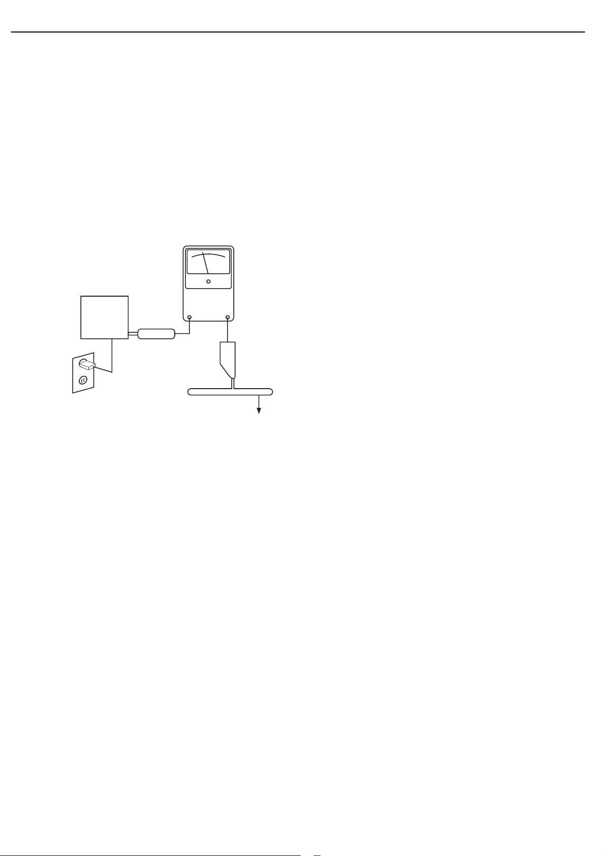
LEAKAGE CURRENT CHECK
Measure leakage current to a known earth ground (water
pipe, conduit, etc.) by connecting a leakage current tester
between the earth ground and all exposed metal parts of the
appliance (input/output terminals, screwheads, metal
overlays, control shaft, etc.). Plug the AC line cord of the
appliance directly into a 120V AC 60Hz outlet and turn the
AC power switch on. Any current measured must not exceed
o.5mA.
ANY MEASUREMENTS NOT WITHIN THE LIMITS
OUTLINED ABOVE ARE INDICATIVE OF A
POTENTIAL SHOCK HAZARD AND MUST BE
CORRECTED BEFORE RETURNING THE APPLIANCE
TO THE CUSTOMER.
3
HS300 harman/kardon
Reading should
not be above
0.5mA
Device
under
test
Leakage
current
tester
Test all
exposed metal
surfaces
Also test with
plug reversed
(Using AC adapter
plug as required)
Earth
ground
AC Leakage Test
Page 4

4
HS300 harman/kardon
HS 300 TECHNICAL SPECIFICATIONS
DVD Player
Pickup: Semiconductor laser, wavelength 650nm
Video signal system: NTSC
Video signal horizontal resolution: >480 lines (DVD)
Video signal-to-noise ratio: >60dB (DVD)
Audio frequency response: DVD (PCM): 20Hz – 22kHz (±1dB)
(Stereo) CD (PCM): 20Hz – 20kHz (±1dB)
Audio signal-to-noise ratio: >80dB (PCM)
Total harmonic distortion: <0.01% (PCM)
Dynamic range: DVD (PCM): >85dB (EIAJ, 2kHz)
CD: >85dB (EIAJ)
FM Tuner
System: PLL quartz-locked digital synthesizer system
Tuning range: 87.50 – 108.00MHz
Antenna terminals: 75 Ohms, unbalanced
Intermediate frequency: 10.7MHz
AM Tuner Section
Frequency range: 520 – 1720kHz
Signal-to-noise ratio: 45dB
Usable sensitivity: Loop 500µV
Distortion: 1kHz, 50% Mod 0.8%
Selectivity: ±10kHz, 30dB
Video Outputs
Component video output: Y: 1 Vp-p/75 ohms, sync negative polarity
Pr: 0.7 Vp-p/75 ohms
Pb: 0.7 Vp-p/75 ohms
Composite video output: 1 Vp-p/75 ohms
S-video output: Y: 1 Vp-p/75 ohms
C: NTSC 0.286 Vp-p/75 ohms
HDMI Output
Video: 480p, 720p, 1080i
HDMI Version 1.0-compliant
HDCP Version 1.1-compliant
Audio Section
Amplifer power: 35 Watts per channel, 20Hz – 20kHz,
<0.5% THD into 6 ohms
Line output: 1 Vrms, 1 kilohm
General
Power requirements: AC 120V, 50Hz
Power consumption: 3W Standby, 380W Maximum
Dimensions (H x W x D): 3-3/16" x 17-15/16" x 15-3/4"
Weight: 10.6 lb
Depth measurement includes knobs, buttons and terminal connections. Height measurement includes feet and chassis.
All features and specifications are subject to change without notice.
Harman Kardon is a registered trademark, and Designed to Entertain is a trademark, of Harman International Industries, Incorporated.
Dolby,Pro Logic and the double-D symbol are trademarks of Dolby Laboratories, registered in the United States and/or other countries. All rights reserved.
DTS,DTS ES and DTS Neo:6 are registered trademarks of DTS, Inc. 96/24 is a trademark of DTS, Inc.
Blu-ray Disc is a trademark of the Blu-ray Disc Association.
HD-DVD is a trademark of the DVD Format/Logo Licensing Corporation (DVD FLLC).
HDMI and High-Definition Multimedia Interface are trademarks of HDMI Licensing LLC.
Kodak is a registered trademark of Eastman Kodak Company.
TiVo is a registered trademark of TiVo Inc.
Windows Media®Audio (WMA) is a proprietary file format developed by Microsoft. Microsoft, Windows and Windows Media are registered trademarks of Microsoft Corporation in the United States
*
and/or other countries.
This product incorporates copyright protection technology that is protected by method claims of certain U.S. patents and other intellectual property rights owned by Macrovision
Corporation and other rights owners. Use of this copyright protection technology must be authorized by Macrovision Corporation and is intended for home and other limited
viewing uses only unless otherwise authorized by Macrovision Corporation. Reverse engineering or disassembly is prohibited.
Page 5
5
HS300 harman/kardon
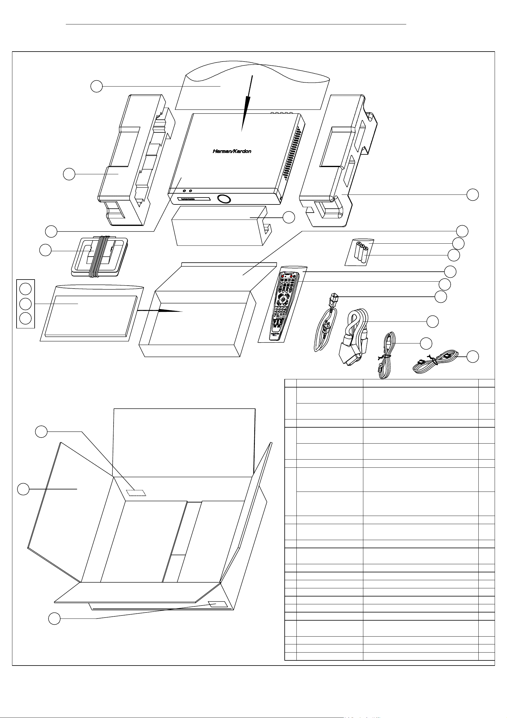
PACKAGE
19
17
5
4
3
6
18
17
16
15
14
13
12
11
9
(230V EU version)
8
7
10
1
2
2
HS300/500 Packing
2006-7-21
No. Part No. Description Qty.
1 0100BZXWE237 Carton box HS300 EU version 1
0100BZXWE238 Carton box HS300 US version 1
1
1
2 Barcode label
3 0100YSSM1E265 Owner manual HS300 US version 1
0100YSSM1E266 Owner manual HS300 EU version 1
1
1
4 Plastic bag for manual 25*35cm
5 0100YSFY3E468 Safety instruction manual HS300 EU 1
0100YSFY3E469 Warning card HS300 US version 1
0100YSFY3E470 Guarantee card HS300 US version 1
1
1
6 0147CNTCTXE042 AM antenna AM-300-AWM 1
7 0147CNTCTXE037 FM antenna FM-075 1
0147CNTCTXE038 FM antennab FM-TV-75-A 1
8 0147CNTLJX5012 SCART cable 1
9 0147CNTACXE052 AC power cord EU version 1
0147CNTACXE053 AC power cord US version 1
10CBADV-19P-19P-2M HDMI 19P/M to HDMI 19P/M CABLE 1
110100RCEHS300 Remote control HS300-RC 1
12 Plastic bag for RC 9*27.5cm
13 battery
14 Plastic bag for battery 6*9cm
15 accessories box 1
16 accessories Polyfoam 2
170100BZFPE100 Polyfoam HS300- left
0100BZFPE101 Polyfoam HS300- right
18 Main unit 1
19
Plastic bag
(230V EU version)
Page 6

6
HS300 harman/kardon
FRONT-PANEL CONTROLS
Standby/On Switch: This is an electrical switch that turns the
HS 300 on for playback, or leaves it in standby mode for quick turn-on
using this switch or the remote control.
Power Indicator: This LED surrounds the Standby/On Switch. When
the HS 300 is plugged into AC power, the LED turns amber to indicate
that the HS 300 is in Standby mode (ready to be turned on). When the
HS 300 is turned on (by pressing the Standby/On Switch or one of the
Source Selectors on the remote), the LED turns blue. If this LED ever
turns red, immediately unplug the HS 300. Check the speaker-wire
connections to make sure no wires are shorting out by touching each
other. If the LED remains red, bring the HS 300 to an authorized
Harman Kardon service provider.
Open/Close: Press this button to open or close the disc drawer.
When the HS 300 is in standby mode, press this button to turn on the
HS 300 and open the drawer. Before pressing this button, always make
sure no objects are blocking the drawer. Remember to close the door
or turn off the HS 300 when you have finished. The door will only close
automatically when the unit is turned off.
Volume Control: Turn this knob to raise or lower the volume,
which will be shown on screen as an increasing or decreasing row
of bars in the Message Display.
Message Display: Various messages appear in this display
in response to commands. In addition, a variety of indicators will
light at various times to display the current source, playback mode
(if appropriate), video settings or other aspects of the HS 300’s
status as described throughout this manual.
Disc Drawer: This drawer holds a disc that is played in the HS 300.
Press the Open/Close button on top of the HS 300 to access it. Be sure
to carefully seat all discs in the recess in the drawer tray. Remember to
close the drawer when you are finished, as it will not close automatically
without turning off the unit.
Headphone Jack: Insert a 1/8" headphone plug into this jack for
private listening. An optional adapter is necessary to use 1/4" or other
size headphone plugs.
USB 1 Port: Gently insert a flash drive, card reader, digital camera
or other USB device, or a USB standard-A cable connected to a USB
device, in this port. Be certain to orient the plug’s plastic tongue so that
it will insert adjacent to the receptacle’s tongue, and seat the plug fully.
You may insert or remove the device at any time; there is no installation
or ejection procedure.The HS 300 is capable of playing MP3 and
Windows Media
AVI files that are stored on the device. The HS 300 can also display
still-image files, but only in the JPEG format.
other USB host/controller to this port, or you may damage both the
HS 300 and your device.
®
WMA audio files, and MPEG 2 and uncompressed
Do not connect a PC or
8
Page 7
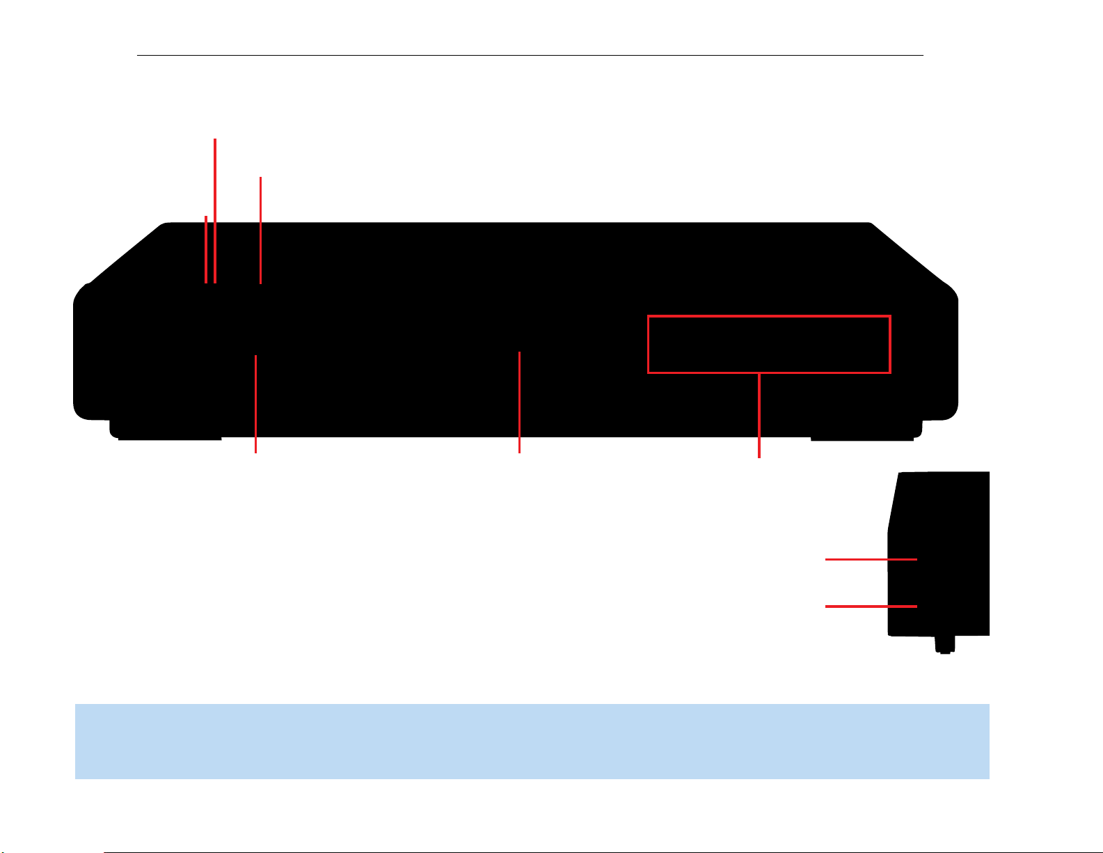
Disc Drawer
Volume Control
Message Display
and Indicators
Power
Indicator
Standby/On
Open/Close
Headphone Jack
USB 1 Port
7
HS300 harman/kardon
FRONT-PANEL CONTROLS
NOTE: To make it easier to follow the instructions throughout the manual that refer to this illustration, a copy of this page may be downloaded from the Product Support section at
www.harmankardon.com.
9
Page 8

8
HS300 harman/kardon
REAR-PANEL CONNECTIONS
AM Antenna Terminals: Assemble the AM loop antenna supplied
and make sure to connect the white wire to the “AM” terminal and the
black wire to the “GND” terminal.
FM Antenna Terminal: Connect the included FM antenna to its
terminal.
Front, Center and Surround Speaker Outputs: Use two-
conductor speaker wire to connect each set of terminals to the correct
speaker. Remember to observe the correct polarity (positive and
negative connections). Always connect the positive lead to the colored
terminal on the HS 300 and the red terminal on the speaker. Connect
negative lead to the black terminal on both the HS 300 and the
the
speaker.
connecting your speakers.
See the Connections section for more information on
Subwoofer Output: Connect a powered subwoofer to this jack.
Subwoofer Trigger Output: A 1/8" mini-plug cable is supplied
with the speakers included in the HS 300 system. Connect one end
of the cable to this jack, and the other end to the trigger input on
the subwoofer to automatically turn on the subwoofer whenever the
HS 300 system is turned on. The subwoofer’s master power switch
must be turned on for the trigger turn-on to operate.
USB 2 Port: Gently insert a flash drive, card reader, digital camera
or other USB device, or a USB Standard-A cable connected to a USB
device, in this port. Be certain to orient the plug’s plastic tongue so that
it will insert adjacent to the receptacle’s tongue, and seat the plug fully.
You may insert or remove the device at any time; there is no installation
or ejection procedure.The HS 300 is capable of playing MP3 and
Windows Media
AVI video files that are stored on the device. The HS 300 can also
display still-image files, but only in the JPEG format.
a PC or other USB host/controller to this port, or you may damage
both the HS 300 and your device.
HDMI™Output: HDMI (High-Definition Multimedia Interface
a newer type of connection for transmitting digital audio and video
signals between devices. If your video display is HDMI-capable, you
may connect the HDMI output to your video display for improved
video performance. It is recommended that you disable the HDMI audio
function of your video display to benefit from the HS 300’s multichannel
audio processing.
®
WMA audio files, and MPEG 2 and uncompressed
Do not connect
™
) is
Auxiliary Analog Audio Inputs: These jacks may be used to
connect an audio-only source component (e.g., tape deck). Do not
connect a turntable to these jacks without a phono preamp.
Analog Audio Outputs: These jacks may be used to connect a
CDR or another audio-only recorder.
TV Analog Audio Inputs: Depending on how you receive broadcast
television, connect the analog audio outputs of your cable television,
satellite or HDTV set-top box to these inputs. Connect the video output
of any of these devices directly to your video display or television. If you
receive television programming using an antenna and tuner built into the
television set, connect the TV’s analog audio outputs to these jacks to
take advantage of the HS 300’s high-quality audio performance.
Coaxial and Optical Digital Audio Inputs: If your source has
a compatible digital audio output, connect it to one of these jacks.
Remember to use only one type of digital audio connection for each
source.
Coaxial Digital Audio Output: If you have connected an audio
recorder to one of the digital audio inputs, you may connect the coaxial
digital audio output to the recorder’s input.
Component Video Monitor Outputs: If your television or video
display is component-video-capable, you may connect these jacks to
the corresponding inputs on your video display.
AC Power Input: After you have made all other connections, plug
the AC power cord into this input and into an unswitched outlet.
Remote Infrared (IR) Input and Output: When the remote
IR sensor on the front panel is blocked, such as when the HS 300 is
placed inside a cabinet, connect an optional IR receiver to the Remote
IR Input jack for use with the remote control. The Remote IR Output
may be connected to the Remote IR Input of a compatible source
device (or other product) to enable remote control through the HS 300.
When several source devices are used, connect them in “daisy chain”
fashion.
Composite and S-Video Monitor Outputs: If your video display
is not equipped with component video inputs, connect one of these
monitor outputs to the corresponding inputs on your television or video
display in order to view the sources. S-video is preferred when available.
Page 9
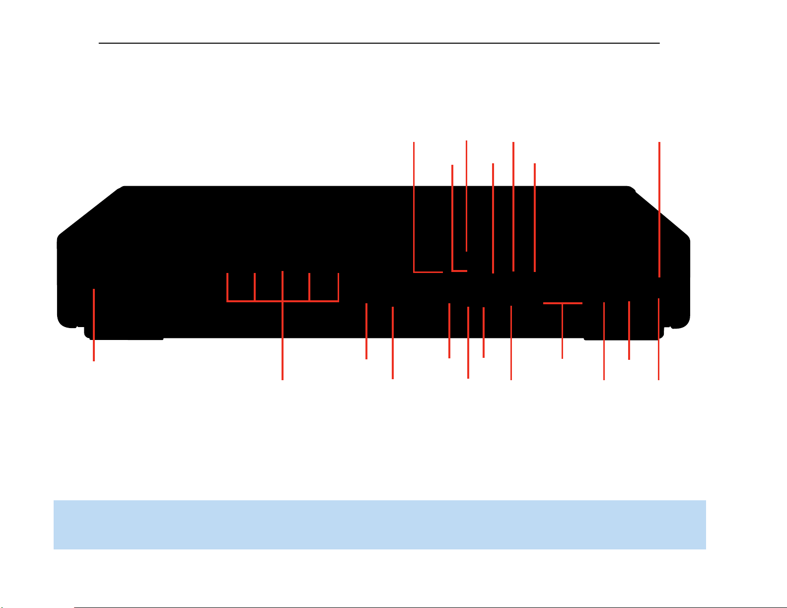
Subwoofer
Output
Remote
IR Input
Remote
IR Output
HDMI
Output
USB 2
Port
FM Antenna
AM Antenna
Subwoofer
Tri gger Output
Component Video
Monitor Outputs
S-Video Monitor
Output
Composite Video
Monitor Output
Optical Digital
Audio Input
TV Analog
Audio Inputs
Auxiliary Analog
Audio Inputs
Analog
Audio Outputs
Coaxial Digital
Audio Output
Coaxial Digital
Audio Input
Speaker Outputs
AC Power Input
9
HS300 harman/kardon
REAR-PANEL CONNECTIONS
NOTE: To make it easier to follow the instructions throughout the manual that refer to this illustration, a copy of this page may be downloaded from the Product Support section at
www.harmankardon.com.
Page 10

10
HS300 harman/kardon
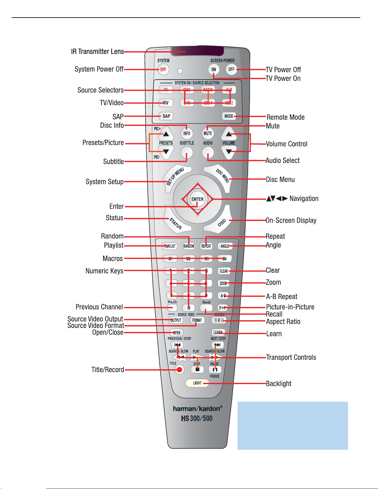
REMOTE CONTROL FUNCTIONS
The HS 300 remote is capable of controlling four devices, including the
HS 300 with its internal disc player and tuner, as well as a TV and
devices connected to the Auxiliary and Digital Audio Inputs. Each time
you wish to use the codes for any component, press the Selector button
for that component to change the button functions to the correct codes.
Each Source Selector is used to power on the HS 300, select the
source indicated, and switch the remote’s mode to operate the source
and the HS 300 system, i.e., volume, mute, source selection and
on-screen displays.The Source Selectors that operate the HS 300’s
internal sources, including the DVD player, the tuner and the USB ports,
are not programmable.As explained in the Initial Setup section, you may
program the TV, Auxiliary and Digital Input Source Selectors to operate
any external components you connect to the HS 300.
TV: Selects the source connected to the analog or digital audio input
assigned to the TV and switches the remote to operate a television set.
Disc: Selects the HS 300’s internal disc player as the source and
switches the remote to Disc mode.
Radio: Selects the HS 300’s internal tuner as the source and switches
the remote to Tuner mode. Additional presses toggle the tuner band
between AM and FM.
AUX: Selects the source connected to the Auxiliary analog audio inputs
and switches the remote to operate the device.
D-IN: Selects the source connected to the digital audio input assigned
to the D-IN source and switches the remote to operate the device.
USB 1: Selects the device connected to the front-panel USB port
(on right side of unit) as the source and switches the remote to operate
the device using the HS 300’s on-screen menu system.
receives codes transmitted by your source component’s original remote
through this lens.The remote is then capable of storing the new code
in the memory for a button you select. See the Installation section for
more information.
Program Indicator: This LED lights up or flashes in one of three colors
as the remote is programmed or operated.
System Power Off Button: Press this button to turn off the
HS 300 or another device.
Screen Power On and Off: Press these buttons to turn your video
display on or off.
Source Selectors: Press one of these buttons to select a source
device, which is a section of the HS 300 (DVD player or tuner) or an
external component where a playback signal originates, e.g., cable TV,
satellite or HDTV tuner. This will also turn on the HS 300 and switch
the remote to the codes that operate the source device.
TV/Video: This button has no effect on the receiver, but is used to
switch video inputs on the TV.
SAP: This button toggles the SAP (Secondary Audio Program) feature
on and off. Some television programs are broadcast with a second
audio track, such as a translation into another language, and this button
allows you to access that audio.
Mode: This button has no effect on the HS 300, but enables you to
switch the remote to another mode so that it operates another device
without selecting it as the source. Each press of the Mode button
changes the remote’s mode in this order: TV, DISC, RADIO,AUX, D-IN,
USB 1 and USB 2, and then back to TV again. The corresponding
Source Selector will light to indicate the mode.
USB 2: Selects the device connected to the rear-panel USB port as
the source and switches the remote to operate the device using the
HS 300’s on-screen menu system.
NOTE: When the remote is switched to USB mode, it does not
directly operate the USB device.The device is navigated and
controlled indirectly using the HS 300’s on-screen menu
system.
The Mode button allows you to change the remote’s mode to control a
different device without selecting that device as a source.This is useful
if, for example, you wish to adjust your video display screen (TV mode)
while watching a DVD (Disc Mode).
Any given button may have different functions, depending on the
remote’s mode. Some buttons are labeled with these functions. For
example, the Preset Buttons are labeled for use as Picture Up/Down
Buttons when viewing JPEGs on a CD or USB device. See Table A8
in the appendix for listings of the different functions for each type of
component.
IR Transmitter Lens: As buttons are pressed on the remote,
infrared codes are emitted through this lens. Make sure it is pointing
toward the component being operated. In Learning mode, the remote
Presets/Picture Up/Down: When the tuner is the source, these
buttons scroll through the preset stations.When the DVD player or USB
is the source these buttons scroll through still images stored on a disc
or USB device.
Disc Info: Press this button to display the Disc Information screen,
which contains detailed information about the current disc.
Mute Button: Press this button to mute the HS 300’s speaker and
headphones outputs temporarily. To end muting, press this button
or adjust the volume. Muting also ends when the system is turned off.
Volume Controls: Press these buttons to raise or lower the volume,
which will be shown in decibels (dB) in the Message Display.
Subtitle: Press this button while a DVD containing subtitle information
is playing to turn subtitles off or select a subtitle language. This setting
will only be in effect for the current disc.
NOTE: When you wish to make a recording, if you have
programmed the recorder’s control codes into the remote, you
will need to simultaneously press both the Subtitle button and
the Record button to transmit the Record control code.
Page 11
NOTE: To make it easier to follow the instructions throughout the manual that refer to this
illustration, a copy of this page may be downloaded from the Product Support section at
www.harmankardon.com.
REMOTE CONTROL FUNCTIONS
11
HS300 harman/kardon
Page 12

12
HS300 harman/kardon
REMOTE CONTROL FUNCTIONS
Audio: Press this button while a DVD is playing to display the current
audio track information and to select another audio format.
Setup Menu: Press this button to access the System Setup menu.
See the Initial Setup section for more information.
Disc Menu: Press this button while a DVD is playing to view the
disc’s menu.
Navigation and Enter Buttons: These buttons are used together
to make selections within the on-screen menu system.
Status: When a DVD or VCD is playing, press this button to view the
Status Bar, which contains playback mode information.
On-Screen Display (OSD): Press this button to activate the
on-screen menu system.
Playlist: Each press of this button toggles between playback in the
disc’s original order and play of a previously programmed playlist.
Press the Play Button to begin playback.
Random: This button turns on or off random play mode, which plays
the tracks on a CD in random order.
Repeat: Press this button repeatedly to cycle through the repeat
modes available with the current disc. Repeat may also be used with
the tracks stored on a device connected to one of the USB ports.
This button is not used to access A-B Repeat mode.
chapters. Press the button once to select the starting point (“A”), and
a second time to select the end of the passage (“B”). Press the button
again to end repeat play.
Pre. Ch: This button has no function with the HS 300. However, for
many televisions pressing this button returns the TV to the previous
channel.
Recall: This button has no function with the HS 300. However, for
many televisions pressing this button displays the channel number, time
or other information.
Picture-in-Picture: This button has no function with the HS 300.
However, for many televisions pressing this button activates the picturein-picture function for simultaneous viewing of two channels or inputs.
Source Video Output: This button selects the S-video, component
video or HDMI output to be used when the internal disc player or a
device connected to one of the USB ports is the source. Since the
HS 300 cannot output S-video and component video simultaneously,
the S-video or YUV (for component video) indicator will light in the
front-panel display when that video output has been selected.
Source Video Format: This button selects the upscaled video
output resolution (480i, 720p, 1080i) when the internal disc player or
a device connected to one of the USB ports is the source.The 720p
or 1080i indicator will light in the front-panel display to indicate the
upscaled resolution.
Angle: When a DVD encoded with multiple camera angles is playing
and when the Angle Icon appears to indicate that the multiple-angle
passage has been reached, press this button to cycle through the
various available angles.
This button is also used to rotate still images. Each press rotates the
image 90 degrees.
Macros: These buttons may be programmed to execute long
command sequences with a single button press.They are useful for
programming the command to turn on or off all of your components, or
for accessing specialized functions for a different component than you
are currently operating.
Numeric Keys: Use these buttons to enter radio station frequencies
when using the tuner, or to select station presets. When a disc is playing,
you may directly enter a track or chapter number to skip to that section
of the disc.
Clear: Press this button to clear a radio station frequency or other
number you have started to enter. This button may also be used to clear
the on-screen displays. Press and hold this button for 5 seconds to
reset the HS 300 to its factory-default settings.
Zoom: When viewing a DVD, VCD or JPEG still image, press this button
repeatedly to enlarge the on-screen image by 2x, 3x, 4x or 5x (2x or
3x only for VCDs) before returning to the original size. While enlarged,
use the Navigation buttons to explore the image.
A-B Repeat: While a disc is playing, the A-B Repeat function allows
you to repeatedly play a passage, which may include several tracks or
Aspect Ratio: This button has no effect on the HS 300, but pressing
it adjusts the aspect ratio on some video displays.
Open/Close: Press this button to open or close the disc drawer. If
the HS 300 is in standby mode, pressing this button will turn it on.
Learn: The HS 300 remote is capable of “learning” individual IR
codes from the original remote that came with your TV or a device that
is connected to the Auxiliary or Digital Audio Inputs. See the Installation
section for instructions for learning remote codes. There is also a quick
reference for learning remote codes on the back of the remote.
Transport Controls: These buttons are used to operate the
HS 300’s internal disc player. Use the controls to skip forward or
reverse by track or chapter; to fast-search forward or reverse; and
to play, pause or stop the disc. After pressing the Pause button, the
skip buttons may be used to step frame-by-frame through a video
presentation, and the fast-search buttons may be used for slow-play.
Title/Record: When used with the internal disc player, this button
allows you to select from the titles stored on the disc, which may include
“making of” or other featurettes. If you have connected a recorder to the
HS 300, this button may be used to make recordings when it is pressed
simultaneously with the Subtitle button.
Backlight: Press this button to turn on the backlight to make it easier
to see the buttons in a darkened room. The backlight will remain on for
a few seconds after your last button press before going out, or you may
turn off the backlight by pressing this button again.
Page 13
Subwoofer
Pre-out
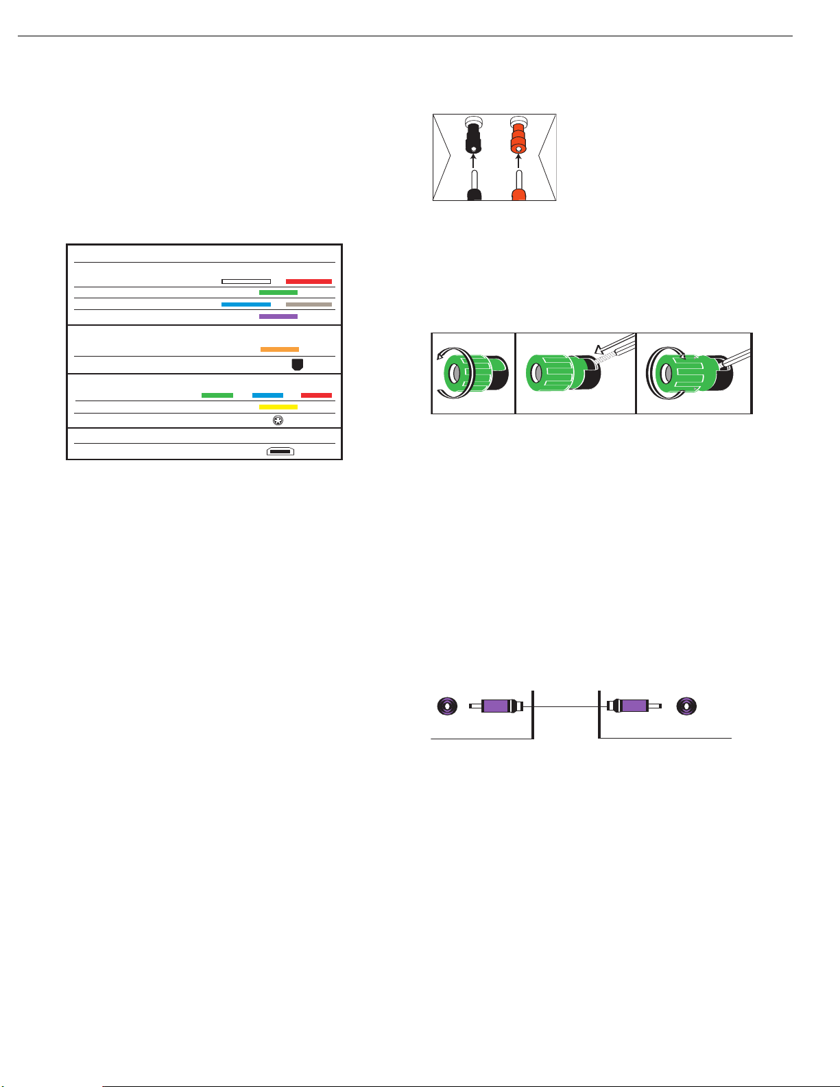
HOW TO USE THE BINDING-POST SPEAKER TERMINAL
COMMENT UTILISER LA BORNE DES HAUT-PARLEURS DE CONNEXION
CÓMO USAR EL TERMINAL DE ALTAVOZ DE POSTE DE SUJECIÓN
Audio Connections
Left Right
Front (FL/FR)
Center (C)
Surround (SL/SR)
Subwoofer (SUB)
Digital Audio Connections
Coaxial
Optical Output Input
Video Connections
Component Y Pb Pr
Composite
S-Video
12 3
+
Audio Connections
Left Right
F
ront (FL/FR)
C
enter (C)
S
urround (SL/SR)
S
ubwoofer (SUB)
D
igital Audio Connections
Coaxial
O
ptical Input
Video Connections
Component Y Pb Pr
Composite
S-Video
HDMI™ Connections
H
DMI
13
HS300 harman/kardon
CONNECTIONS
There are different types of audio and video connections used to
connect the HS 300 to the speakers and video display, and to connect
any source devices to the HS 300. To make it easier to keep them all
straight, the Consumer Electronics Association (CEA) has established
a color-coding standard. Table 1 may be helpful to you as a reference
while you set up your system.
Table 1 – Connection Color Guide
Types of Connections
This section will briefly review different types of cables and connections
that you may use to set up your system.
Speaker Connections
Speaker cables carry an amplified signal from the receiver’s speaker
terminals to each loudspeaker. Speaker cables generally contain two
wire conductors, or leads, inside plastic insulation. The two conductors
are usually differentiated in some way, by using different colors, or
stripes, or even by adding a ridge to the insulation.
The differentiation is important because each speaker must be
connected to the HS 300’s speaker-output terminals using two wires,
one positive (+) and one negative (–). This is called speaker polarity.
It’s important to maintain the proper polarity for all speakers in the
system. If some speakers have their negative terminals connected to
the HS 300’s positive terminals, performance can suffer, especially for
the low frequencies.
Always connect the positive terminal on the loudspeaker, which is
colored red, to the positive terminal on the HS 300, which is colored
as shown in the Connection Color Guide (Table 1). Similarly, always
connect the black negative terminal on the speaker to the black
negative terminal on the HS 300. The wires in the speaker system
included with your HS 300 Home Theater System are color-coded
with bands.
The HS 300 uses binding-post speaker terminals that can accept
banana plugs or bare-wire cables, should you wish to upgrade your
system in the future.
Banana plugs are simply plugged into the hole in the middle of the
terminal cap. See Figure 1.
Figure 1 – Binding-Post Speaker Terminals With
Banana Plugs
Bare wire cables are installed as follows (see Figure 2):
1. Unscrew the terminal cap until the pass-through hole in the collar
is revealed.
2. Insert the bare end of the wire into the hole.
3. Screw the cap back into place until the wire is held snugly.
Figure 2 – Binding-Post Speaker Terminals With Bare Wires
Subwoofer
The subwoofer is a specialized type of loudspeaker that is usually
connected in a different way. The subwoofer is used to play only the
low frequencies (bass), which require much more power than the other
speaker channels. In order to obtain the best results, the HS 300
includes a powered subwoofer that contains its own amplifier on board.
A line-level (nonamplified) connection is made from the HS 300’s
Subwoofer Output to a corresponding jack on the subwoofer.
See Figure 3.
Although the subwoofer output looks similar to the analog audio jacks
used for the various components, it is filtered and only allows the low
frequencies to pass. Don’t connect this output to your other devices.
Although doing so won’t cause any harm, performance will suffer.
Figure 3 – Subwoofer
Connecting External Source Devices to the
HS 300
The HS 300 is designed to process audio input signals.These signals
originate in what are known as “source devices,” including the internal
DVD/CD player, a DVR (digital video recorder) or other recorder, a tape
deck, a game console, a cable or satellite television box, a flash drive
or an MP3 player. Although the tuner and disc player are built into the
HS 300, they also count as sources, even though no external connections are needed, other than the FM and AM antennas.
In general, separate connections are required for the audio and
video portions of the signal. The types of connections used depend
upon what’s available on the source device, and for video signals, the
capabilities of your video display.
Page 14
FM
AM
SUB
FR
FL
SR
SL
C
14
HS300 harman/kardon
INSTALLATION
You are now ready to connect the various components to the HS 300.
Before beginning, make sure that all components, including the HS 300,
are turned completely off and their power cords are unplugged. Don’t
plug any of the power cords back in until you have finished
making all of your connections.
The HS 300 generates heat while it is playing. Select a location that
leaves several inches of space on all sides. It is preferable to avoid
completely enclosing it inside a cabinet. It is also preferable to stack
components on separate shelves rather than directly on top of the
HS 300. Some surface finishes are delicate. Try to select a location
with a sturdy surface finish.
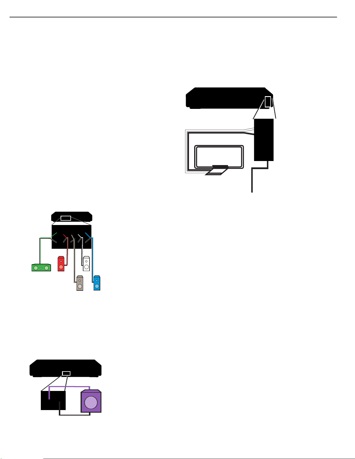
Step One – Connect the Speakers
If you have not yet done so, place your speakers in the listening room
as described in the Speaker Placement section above.
Connect the center, front left, front right, surround left and surround right
loudspeakers to the corresponding speaker terminals on the HS 300.
Remember to maintain the proper polarity by always connecting the
positive and negative terminals on each speaker to the positive and
negative terminals on the receiver. Use the Connection Color Guide
on page 16 as a reference. See Figure 14.
Step Three – Connect the Antennas
Connect the FM and AM antennas to their terminals. Keep in mind that the
AM terminals are polarized. Connect the white lead to the AM terminal and
the black lead to the GND terminal.
Figure 16 – Antenna
Connections
Step Four (Optional) – Connect Any External
Source Components
Figure 14 – Speaker Connections
Step Two – Connect the Subwoofer
Connect the Subwoofer Output on the HS 300 to the line-level input on
your subwoofer. Use the 1/8-inch mini-plug cable packed with the
speaker system to connect the Subwoofer Trigger on the HS 300 to the
External Trigger Input on the subwoofer. See Figure 16. The trigger will
automatically turn on the subwoofer when the HS 300 is turned on.
Consult the owner’s guide for the subwoofer for additional information.
Although the HS 300 already contains an FM/AM tuner and DVDAudio/Video player on board, you may have other components you
would like to use with your home theater system. The HS 300 can
accommodate up to two analog audio, two digital audio and two USB
devices.You may connect different devices to the digital and analog
audio inputs; they are treated as separate sources. You will notice that
the HS 300 has no video inputs. Connect each source’s video output
directly to your television, but connect its audio output to the HS 300
to benefit from the multichannel surround sound. If you wish to make a
recording from the disc player, you will only be able to make an analog
recording of copy-protected materials, and you will need to connect the
video inputs of your recorder to either the composite or S-video output
of the HS 300.
When deciding which components to connect to each input, bear in
mind that the remote may be programmed to control the device. By
default, the Auxiliary input is preprogrammed to operate a VCR or DVR
(TiVo), and the digital inputs (D-IN) are preprogrammed to operate a
cable or satellite set-top box. Thus, you may want to connect your
components accordingly. However, you may reassign the product types
when you program the remote, and any compatible component with
the correct audio outputs may be connected to any of the sources.
Use the worksheets in the Appendix to note which connections you will
use for each of your source devices.
Figure 16 – Subwoofer Connection
For each source, select a source input (TV, AUX, D-IN). In Table 2 we
recommend connecting certain types of sources to certain source inputs
to make it easier to program and use the remote control.
Decide which audio connections you will use. If your source has them,
either the coaxial digital or the optical digital audio connection.
use
Page 15
15
HS300 harman/kardon
INSTALLATION
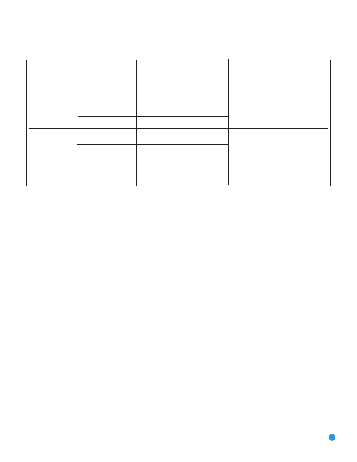
Table 2 – Recommended Source Component Connections
Device Type HS 300 Source Input Audio Connections Video Connections
VCR, DVR, PVR, • AUX • Analog inputs and outputs • Connect recorder’s video output directly
TiVo®or other to video display
audio/video recorder • D-IN • Coaxial input and output • For recording, use S-video or
composite video output
CDR, MiniDisc, • AUX • Analog inputs and outputs Not required
cassette
• D-IN • Coaxial input and output
TV, cable TV, satellite, • TV • Analog inputs or Not required for television set; connect other
HDTV or other device • Coaxial or Optical input device’s video output directly to video display
that delivers television
programs
Digital camera*, flash • USB 1 • Side input at front of unit Included in single USB connection
drive, hard disc drive or • USB 2 • Rear-panel input
other USB device**
• D-IN • Coaxial or Optical input
* The HS 300 is only compatible with cameras that output files in the JPEG format.
** The HS 300 is only compatible with video files in the MPEG 2 and AVI formats. Do not connect a PC or other “host” USB device to the HS 300’s USB ports.
Audio/Video Recorder
Select either the analog or digital audio connections for your recorder.
Each connection is treated as a separate source by the HS 300.
If you are using analog audio, connect the analog audio outputs on your
recorder to the AUX analog audio inputs on the HS 300, and the AUX
analog audio outputs to the analog audio inputs on your recorder.
TV, Cable, Satellite, HDTV
Select either the analog or coaxial or optical digital audio connection
for your device.You may select either for the TV source.
If you are using analog audio, connect the analog audio outputs on your
TV or set-top box to the TV analog audio inputs on the HS 300.
See Figure 19.
See Figure 17.
Figure 19 – TV Analog Audio Inputs
Figure 17 – AUX Analog Audio Inputs and Outputs
If you are using the digital audio connections, you will need to use the
D-IN coaxial input and output, as there is no optical audio output on the
HS 300. See Figure 18.
Figure 18 – D-IN Coaxial Digital Audio Input and Output
When connecting a recorder, be careful to always connect one device’s
input to the other device’s output.
If you would like to record video from the HS 300’s internal disc player
or a USB device, connect the recorder’s S- or composite video input to
If you are using digital audio, your TV or set-top box must have a
compatible digital audio output, which should be connected to either
the Coaxial or Optical Input on the HS 300. See Figure 20. The set-top
box should be selected as the D-IN source.
Figure 20 – Coaxial and Optical Digital Audio Inputs
When you select TV as your source input, you may select between the
analog audio (line) or either digital audio input.
If you are using a cable or satellite set-top box to receive television
broadcasts, connect
one of its video outputs directly to your video
display.
either the S- or composite video output on the HS 300. When recording from the S-video output, select the S-video output in the Video
Setup Menu, as component and S-video outputs are not available
simultaneously. Connect
one video output on the recorder directly to
your video display or television.
21
Page 16
16
HS300 harman/kardon
INSTALLATION
Digital Camera, Flash Drive, Hard Disc Drive
The HS 300 is equipped with two independent USB ports for use with
USB devices, but not “host” devices, such as your PC. Do not connect
your PC to either of the HS 300’s USB ports.
The USB 1 port is located on the right side of the HS 300, near the
front panel. See Figure 21.
Figure 21 – USB 1 Port
The USB 2 port is located on the rear panel. See Figure 22.
Figure 22 – USB 2 Port
You may connect any USB device, such as a digital camera, flash drive
or hard disc drive to either USB port. The HS 300 will automatically
recognize any of the following types of files stored on the device: MP3
or WMA audio; MPEG 2 or uncompressed AVI video; JPEG still image.
You may navigate the files using the HS 300’s on-screen menu system,
as explained in the Operation section.
NOTES:
• The HS 300 is not compatible with digital cameras that do
not produce images in the JPEG file format.
• There is no special procedure for installing or removing USB
devices; simply plug in or remove the device at any time.
Step Five – Connect Video Display
Only video connections should be made between the receiver and
your video display (TV), unless your TV is the source for your television
programming (see above).
Determine what types of video your display is capable of handling.
Remember that HDMI is preferred, followed by component video
S-video and then composite video.
Select the best type of video your display is capable of handling,
and connect only one of the HS 300’s video outputs to your display.
See Figure 23.
AC Input, and plug the other end of the cord into a working, unswitched
AC outlet. See Figure 24. If you are using any external components with
the HS 300 system, you may plug those into AC power at this time.
Figure 24 – AC Input for Power Cord
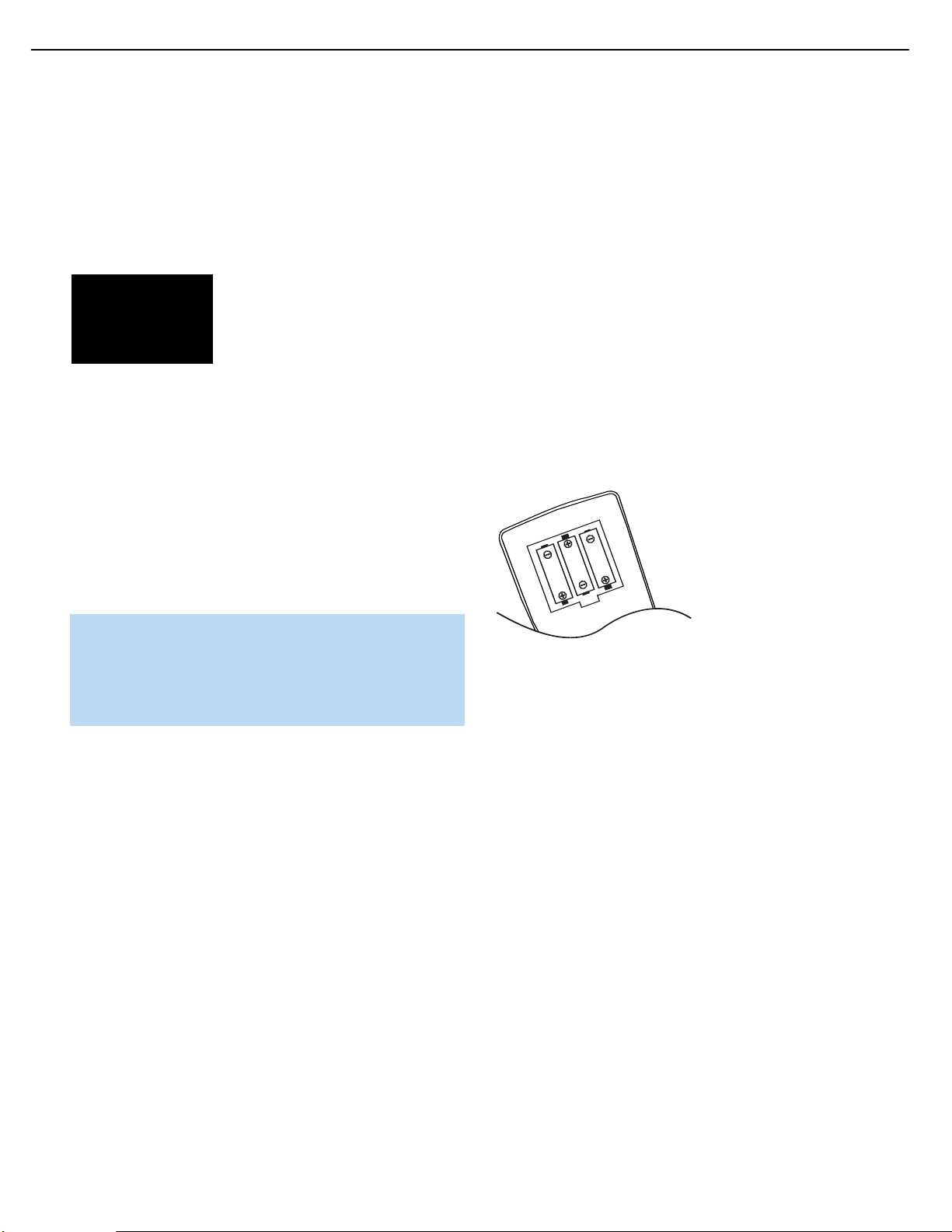
Step Seven – Insert Batteries in Remote
The HS 300 remote control uses three AAA batteries (included).
To remove the battery cover located on the back of the remote, firmly
press the ridged depression and slide the cover towards the top of
the remote.
Insert the batteries as shown in Figure 25, making sure to observe
the correct polarity.
Figure 25 – Remote Battery
Compartment
When using the remote, remember to point the lens toward the front
panel of the HS 300. Make sure no objects, such as furniture, are
blocking the remote’s path to the receiver. Bright lights, fluorescent lights
and plasma video displays may interfere with the remote’s functioning.
The remote has a range of about 20 feet, depending on the lighting
conditions. It may be used at an angle of up to 30 degrees to either
side of the HS 300.
If the remote seems to operate intermittently, or if pressing a button
on the remote does not cause one of the source selectors to light up,
then make sure the batteries have been inserted correctly, or replace
all three batteries with fresh ones.
Step Eight – Program Sources Into the Remote
The HS 300 remote is capable of controlling not only the HS 300,
but it may also be programmed to control many brands and models of
VCRs, cable boxes, satellite receivers, cassette decks and TVs.
Figure 23 – Video Outputs
Step Six – Plug In AC Power
Having made all of your wiring connections, it is now time to power
up the HS 300. The HS 300 comes with a detachable power cord,
which enables you to pre-install all wiring before final installation of the
HS 300. Connect the female end of the power cord to the HS 300’s
It may help to think of the remote as a book with pages. Each page
represents the button functions for a different device. In order to access
the functions for a particular device, you first need to turn to that page.
This is done by pressing the Source Selector buttons to access the
codes for the devices programmed into the remote.There is no “page”
specifically set aside for the HS 300’s system functions. Instead, the
volume and audio controls are always active, and the functions for the
internal disc player and tuner are active when those sources are selected.
Page 17
17
HS300 harman/kardon
INSTALLATION STEPS
At the factory, the codes to operate the HS 300 are preprogrammed.
If you have other source devices in your system, follow these steps to
program the correct codes into the remote.
1. Using the codes in Tables A9–A13 of the Appendix, look up the
product type (e.g., TV, cable TV box) and the brand name of your
source.The number(s) listed are potential candidates for the correct
code set for your particular device.
2. Turn on your source device.
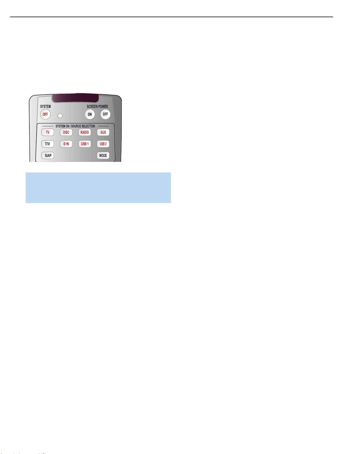
3. By default, the AUX Source Selector is assigned device type
VCR/Tivo, and the D-IN Source Selector is assigned device type
CBL/SAT. However, you may reassign the device type of either
Source Selector.
To program the device type for the AUX or D-IN Source Selector:
5. Enter a three-digit code from Step 1 above.
a) If the device turns off, then press the Source Selector again to
accept the code, and it will flash. The remote will exit Program
mode.
Figure 26 – Source Selectors
a) Press and hold the Source Selector for at least three seconds until
the Program Indicator LED flashes in green. The Source Selector
button will also light up in red, and will then flash once, twice or three
times to indicate the current device assignment (refer to Table 3).
b) To change the device assignment, within five seconds hold down
the Mode button on the remote while pressing the Numeric Key
corresponding to the desired device type.
c) Release and press the Source Selector button to record the entry.
Table 3 – Device Types for AUX and D-IN Source
Selectors
Device Type Indicated by Flashes Numeric Key
to Select
Tape One 1
VCR/TiVo Two 2
CBL/SAT Three 3
Default (VCR/TiVo for Ten (or many fast flashes) 0
AUX; CBL/SAT for D-IN)
NOTE: The TV Source Selector is programmable, but its device
type may not be changed. Since the Disc and Radio Source
Selectors control the HS 300 itself, they are not programmable.
USB devices are also controlled using the HS 300’s menu system, and these Source Selectors are also not programmable.
4. To program a particular product into the TV, AUX or D-IN Source
Selector, press and hold the Source Selector and the Mute Button
simultaneously until the Program Indicator flashes in amber, then
release. See Figure 26.
b) If the device does not turn off, try entering another code. If you
run out of codes, you may search through all of the codes in the
remote’s library for that product type by pressing the
button repeatedly until the device turns off. When the device turns
off, enter the code by pressing the Source Selector, which will
flash. The remote then exits Program mode.
NOTE: When you have entered a valid three-digit product code,
the Program Indicator LED will flash in green. However, if you
enter an invalid product code, the Program Indicator LED will
flash in red. You may then enter another code.
6. Once you have accepted a code, it’s a good idea to try using some
other functions to control the device. Sometimes manufacturers
use the same Power code for several different models, while other
codes will vary.You may wish to repeat this process until you’ve
programmed a satisfactory code set that operates most of the
functions you frequently use.You will be able to program individual
codes into the buttons on the HS 300 remote by “learning” them
from the original component’s remote as explained in Step 8 below.
7. You may find out which code number you have programmed by
pressing and holding the Source Selector and Mute Button simultaneously to enter Program mode.Then press the Enter Button, and
the Program Indicator LED will flash in green in the code sequence.
One flash represents “1”, two blinks for “2”, and so forth. A series of
many fast flashes represents “0”. Record the codes programmed for
each device in Table 4.
⁄ or ¤
Table 4 – Remote Control Codes
Source Input Product Type Remote Control Code
AUX
D-IN
TV TV
8. After you have programmed a code set to operate a device, test the
functions to see which ones may be missing or not operating correctly.
You may “learn” individual key codes if you have the device’s original
remote control by following this procedure:
Page 18
18
HS300 harman/kardon
INSTALLATION
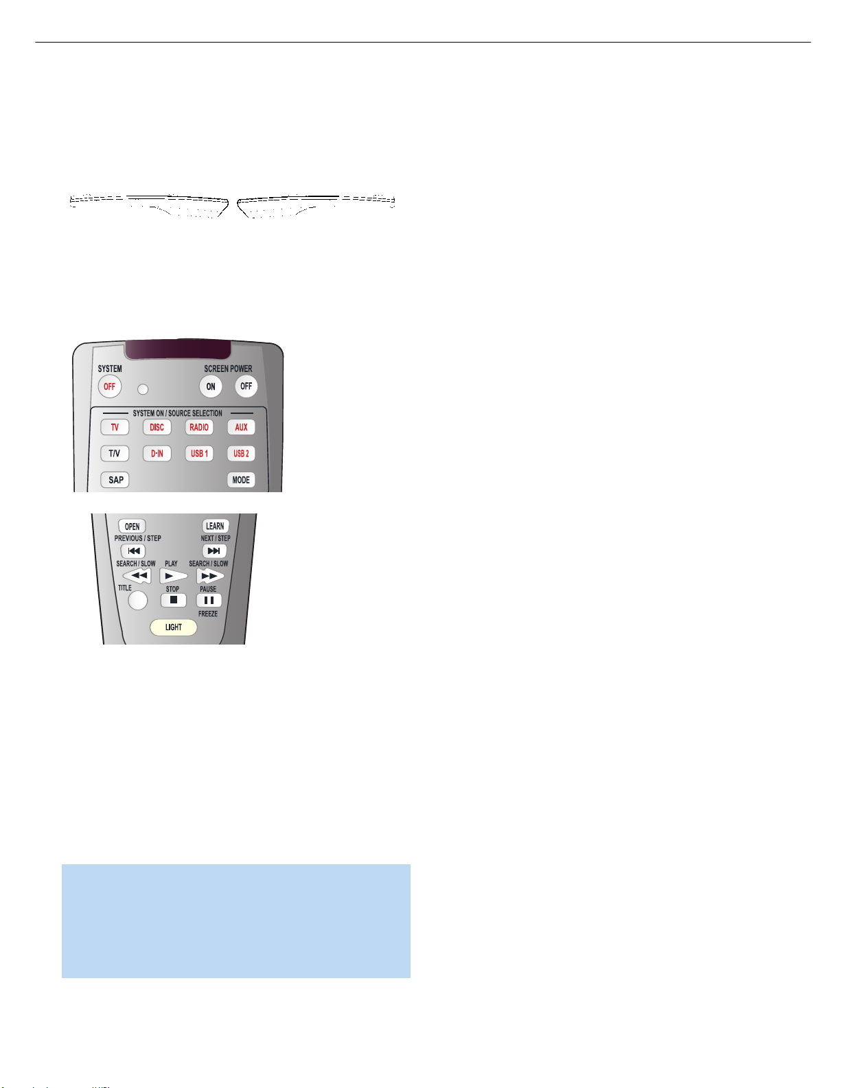
a) Place the two remotes so that their IR transmitters face each other
end to end, separated by about one inch. See Figure 27. The HS
300 remote’s transmitter also serves as an IR receiver during the
learning process.
Figure 27 – HS 300 and Original Remote Head-to-Head
b) Place the HS 300 remote in Learning mode by simultaneously
pressing and holding the Source Selector you wish to learn a
code for and the Learn buttons until the Program Indicator flashes
in amber, then release. See Figure 28.
If you are unable to locate a code set that correctly operates your
source device, you may still connect the source to the HS 300 and
operate it using the device’s original remote control. Alternatively, you
may wish to consider purchasing Harman Kardon’s optional TC 30
activity-based remote, which is programmed by accessing a large database of product codes on the Internet. The TC 30 is also capable of
“learning” codes from your device’s original remote.
Most of the button labels on the remote describe the button’s function
when used to control the HS 300. However, the button may perform a
very different function when used to control another device. Refer to the
Remote Control Function List, Table A9 in the Appendix, for a list of
each button’s functions with the various product types.
If you wish, you may program Macros, which are preprogrammed code
sequences that execute many code commands with a single button
press.You may also program “punch-through” codes, which allow the
remote to operate the volume, channel or transport controls of another
device without having to switch the remote to the mode for that device.
See pages 55 through 56 for instructions on these advanced programming functions.
If you make a mistake in programming your remote and you wish to
completely reset it to its factory defaults, follow this procedure:
1. Simultaneously press any Source Selector and the “0” Numeric Key
until the Program Indicator LED flashes in amber, and release.
Figure 28 – Learning Remote Commands
c) Press and hold the button on the HS 300 remote you wish to
program with the new code until the Program Indicator remains
steadily lit in amber, then release it.
d) Press and hold the button on the device’s original remote whose
code you wish to “learn” until the Program Indicator flashes in
green, then release it.
e) You may program additional buttons by repeating steps c) and d).
To exit Learning mode, press the Learn button once. If you prefer,
you may wait for the remote to “time out” and exit Learning mode
on its own, but this will take about thirty seconds.
NOTE: The following buttons on the remote are not programmable,
and are not subject to learning new codes: System Off, all of the
Source Selectors, Mode, Subtitle, Audio, Status, Source Video
Output, Source Video Format, Learn and Light. If you learn a
code into a Macro key, you will not be able to program a Macro
into that key, as the learned code will take priority.
2. Enter the numeric code “333”.
3. The Program Indicator LED will light steadily in green, indicating that
it is resetting the remote. Do not press any buttons while the LED is
lit green. When it goes dark, the remote has been completely reset.
Step Nine – Turn On the HS 300
Plugging the HS 300 into AC power places it in Standby mode, which
is indicated by the Power Indicator (surrounding the Standby/On Switch)
turning amber.
There are several ways in which the HS 300 may be turned on from
Standby mode.
a) Press the Standby/On Switch on the top panel. See Figure 29.
Figure 29 – Standby/On Switch on Top Panel
b) Press the Open/Close Button on the top panel. See Figure 30.
Figure 30 – Open/Close Button
Page 19
19
HS300 harman/kardon
INSTALLATION
Pressing the Open/Close Button will also select the Disc Player as the
source input, and open the disc drawer.
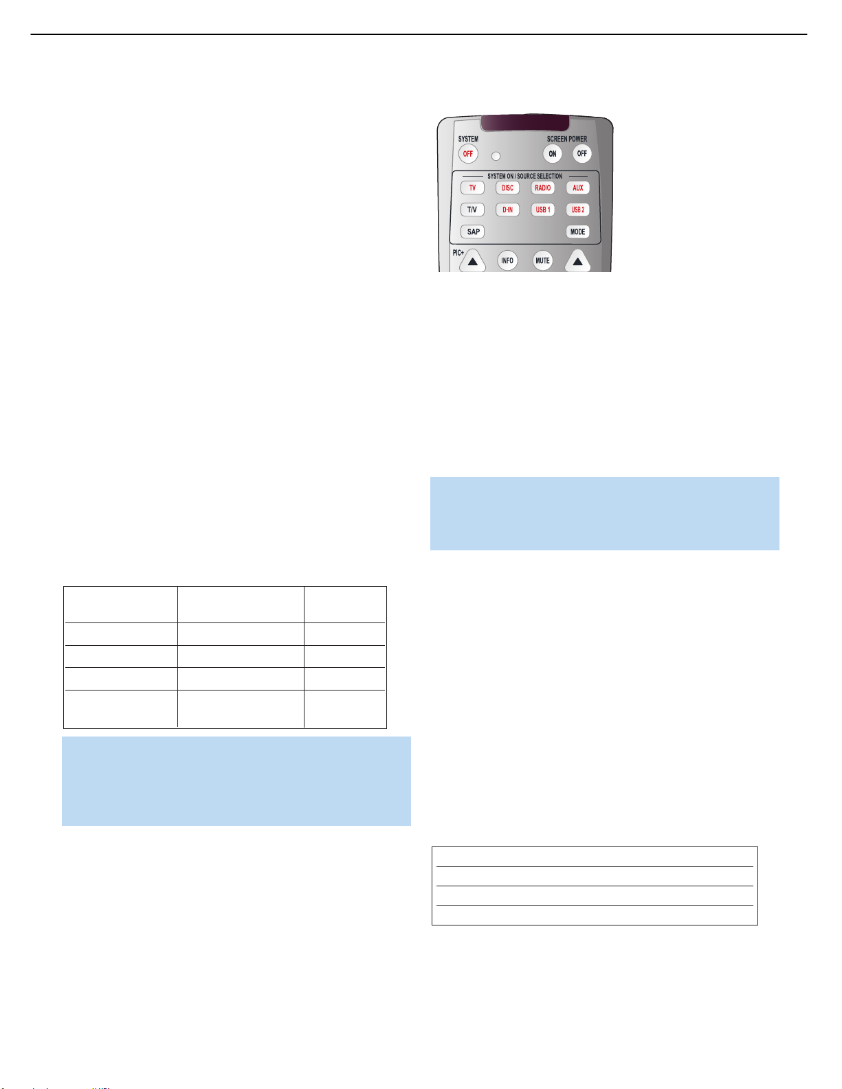
c) Using the remote, press any one of these buttons: TV, DISC, RADIO,
D-IN, USB 1 or USB 2, the HS 300 will select that source. See
Figure 31.
Figure 31 – Source Selectors
NOTE: Any time you press one of the Input Selectors on the
remote (i.e.,TV, DISC, RADIO, AUX, D-IN, USB 1 or USB 2),
the remote will switch modes so that it will transmit the codes
programmed to operate that device.
Page 20

20
HS300 harman/kardon
INITIAL SETUP
Before you begin enjoying your new home theater, a few adjustments
should be made to configure the system.
Make sure that you have connected a video display to one of the video
monitor outputs.When you turn on your display and the HS 300, you
should see the HS 300’s splash screen. The last-used source will be
selected. If it was the Disc Player, the HS 300 will determine whether a
disc is loaded and, if so, begin play. If not, the splash screen will remain.
For other sources the corresponding screen will be displayed.
Using the On-Screen Menu System
The HS 300 uses two types of menu screens: Setup menus and
Source menus.
Press the Setup Menu button on the remote to display the System
Setup menu. See Figures 32 and 33.
Most of the screen contains the various configuration settings, with the
current setting displayed to the right. Use the Navigation buttons to
highlight a setting. See Figure 34.
Figure 34 – Selecting a Setting
Press the Enter Button to make changes to the setting. The screen’s
appearance will change to alert you that you are affecting the system
configuration. The selected setting line will remain fully lit, and the setting
itself will change from a button to plain text with arrows on both sides.
The remaining setting lines on the screen will dim. On the options line
at the bottom of the screen, the current setting will be highlighted as
a button. Use the
‹/› buttons to scroll through the options list. As
various options are highlighted at the bottom of the screen, the new
setting will appear on the setting line. See Figure 35.
Figure 32 – Setup Menu Button
Figure 33 – System Setup Menu Screen
All of the HS 300’s menu screens follow the same basic format.
The top line is the Main Menu line.The first six selections correspond
to the source inputs. Selecting one of these menus also selects that
source.The last item is the Setup menu that is used to configure the
HS 300’s system settings.
The HS 300 displays instructions at the bottom of the screen to guide
you in making your selections.When adjusting a setting, available
options will appear below the instructions line.
On the left side of the screen are navigation icons that may be used to
access the submenus or display information. Use the Navigation buttons
on the remote to highlight an icon, and press the Enter button to select
or deselect it. When the icon is selected, it will look like a button that
has been pressed in. When it is deselected, it looks like a button in the
out position.
Figure 35 – Choosing a New Option for a Setting
Press the Enter Button when the desired setting is highlighted, and use
⁄/¤ buttons to select another setting line.
the
When you have made all desired adjustments to the current submenu,
use the Navigation buttons to highlight the icon for the next submenu,
and press the Enter Button to switch to that submenu.
When you have finished adjusting all settings, press the OSD button
(but not the Setup Menu button) to clear the menu from the display.
See Figure 32.
Step One – System Setup
In this step you will configure some basic system settings using the
System Setup submenu. Press the Setup Menu button and the Enter
button as explained above to access the settings in this submenu. Your
screen should look similar to the one shown in Figure 33.
DISPLAY LANGUAGE: This setting selects the language that will be
used for the HS 300’s OSD menus and other system messages.
The default is English, but you may select French, Spanish, German
or Italian.
Page 21

21
HS300 harman/kardon
INITIAL SETUP
PREFERRED SUBTITLE LANGUAGE: This setting selects the language
used for the display of subtitles.The default setting is OFF, to play discs
without subtitles.To set the player so that subtitles will always play in a
specific language when they are available, select from the choices
shown.
If you do not find your preferred language in the options list, you may
select a preferred language by first pressing the
UNKNOWN or OTHER is highlighted in the options list. Press the Enter
Button, and you will be prompted to enter a four-digit language code.
See Figure 34. Select the code for the desired language from the list
in Table A14 in the Appendix, and use the Numeric Keys to enter the
code, then press the Enter Button.
This procedure selects a preferred subtitle language, but it will only be
available when the disc being played contains that language.The list of
subtitles available on any given disc is always shown on the disc jacket,
usually at the bottom of the back cover. The subtitles may also be
switched on or off, or a new language selected during playback using
the Subtitle Button.
If you have selected a subtitle language and subtitles do not appear on
screen, press the Subtitle Button to display the Subtitle banner. Press
the Enter button to display the subtitle language options available on
the disc. Use the
the Enter button. Then use the
button, and press Enter to clear the banner from the screen.
If subtitles still do not appear, press the Disc Menu Button to make
sure that subtitling has been selected in the disc’s menu system. See
Figure 32.
‹/› Buttons to select the desired option, and press
‹/› buttons to navigate to the Done
‹/› Buttons so that
Figure 36 – Entering a Code for a
Subtitle Language
STATUS BAR TIME-OUT: This setting selects the timeout interval for
the on-screen Status Bar that appears at the top of your video screen
when the Status Button is pressed while a disc is playing. During DVD
playback, the status bar shows the current title and chapter, playback
mode, the elapsed or remaining time in the current chapter or title, a
setting to adjust the time display, and a temperature bar for the time
display.
You may program the status bar to remain on screen for either five or
20 seconds after the Status Button is pressed. When OFF is selected,
the timeout is disabled, and the status bar will remain on the screen until
the Status Button or Clear Button is pressed. We strongly recommend
programming the Status Bar to disappear on its own to avoid burning
its image into a plasma or CRT display.
PARENTAL CONTROL: The HS 300’s password system allows you to
restrict viewing of certain materials that may not be suitable for younger
members of the household by requiring the viewer to enter a password
to view those materials.The system is based on rating information
encoded in some DVDs that classifies materials into eight levels, roughly
corresponding to the Motion Picture Association of America (MPAA)
voluntary ratings system:
Level 1G: Corresponds to the MPAA’s “G” (General Audiences) rating,
and is considered suitable for all viewers.
Level 2: Intermediate level between the “PG” and “G” ratings.
Level 3PG: Corresponds to the MPAA’s “PG” (Parental Guidance) rating.
Level 4PG13: Corresponds to the MPAA’s “PG-13” (Parental
Guidance and 13 years old) rating.
Level 5: Intermediate level between the “R” and “PG-13” ratings.
Level 6PG-R: Corresponds to the MPAA’s “R” (Restricted) rating.
Level 7NC17: Corresponds to the MPAA’s “NC-17” (17 years and
older) rating.
Level 8Adult: All DVDs, including adult materials, can be played.
Off: Any DVD may be viewed without entering the password.
NOTE: Due to the variations in how DVD discs are authored,
the subtitle languages displayed by the HS 300 may not accurately reflect the actual languages available on the disc. It is
recommended that subtitles be selected using the disc’s menu.
PANEL TIME-OUT: This setting allows you to select the length of time
the Front-Panel Display remains lit during disc playback (as some people
find the front-panel display distracting while a movie is playing). You may
program the HS 300 to refresh the front-panel display only when a
button is pressed on the remote or front panel, and to turn the display
off again after either five or 20 seconds.When the display is off, the
blue Power Indicator will remain lit to remind you that the unit is turned
on. When the Panel Time-Out setting is set to “Off,” the display remains
lit at all times.
The HS 300 is shipped from the factory with the parental control system
unlocked (no password is required to view any DVD), and with the
password set to the four-digit code “8888.” To activate the system,
highlight the Parental Control Setting on the SYSTEM SETUP submenu,
and press the Enter Button. You will be prompted to enter the four-digit
password. See Figure 37.
Figure 37 – Parental Control
Page 22

22
HS300 harman/kardon
INITIAL SETUP
If you have entered the password correctly, the ratings levels will be
displayed on the options line. See Figure 38.
Figure 38 – Parental Control Ratings
Scroll to the left or right to select a rating, or to display additional
options, including Off and New Password. See Figure 39.
Figure 39 – Additional Parental Control Ratings
The first time you use the HS 300, it is recommended that you scroll
to the New Password setting and press the Enter Button to enter a new
password. Use the Numeric Keys to enter your new password once at
the New Password prompt, and a second time at the Confirm Password
prompt. See Figures 40 and 41. The HS 300 will return to the screen
shown in Figure 38, and you may then change the Ratings Setting.
Once you press the Enter Button and return to the
submenu, the new password will take effect.
SYSTEM SETUP
DISC RECOGNITION: The setting for the Disc Recognition feature,
when turned on, allows you to stop a DVD-Video disc, remove it from
the player, play another disc, and then resume playback of the original
disc at a later time from the point at which you paused. When a previously played disc is reinserted in the HS 300, you will be presented with
an on-screen status message asking whether you wish to start playback
from the beginning of the disc or resume at the point where you left off.
Even when the setting is activated, you must press the Stop Button
either once (Resume mode) or twice (Stop mode), but not the Pause
Button. The unit may be turned off between discs. The HS 300 can
store the information for up to 100 DVDs at a time.
PBC SUPPORT: This setting controls the activation of PBC (Play Back
Control) Support for VCD discs. If you plan to play VCD discs, which are
a CD-ROM-based format that predates DVD, we recommend that the
setting be turned ON. However, with PBC enabled, the Repeat Track,
Repeat Disc and Random functions may not be available for VCDs.
NOTE: The PBC indicator will light in the front-panel display any
time a VCD encoded with playback control is loaded, regardless
of whether the PBC Support setting has been activated.
SCREEN SAVER: The HS 300 offers a Screen Saver option to protect
your TV or video display from damage that may occur if the player is left
turned on with the same still image for a period of time, as there is a
possibility that the image may be “burned” into some display devices.
This is particularly important for plasma displays and some CRT devices.
Set Screen Saver to ON so that the HS 300 will run the screen saver
when no action has been detected for two minutes. Press a desired
command key on the front panel or remote to “wake” the HS 300 and
resume normal operation.
IMPORTANT NOTE: If the screen cursor is left either on the
Main title line (without selecting a source or the Setup menus)
or on one of the navigation icons on the left side of the screen,
the screen saver will not be activated. Moreover, some discs,
such as DVD-Audio discs and JPEG discs, can leave a still
image displayed indefinitely. Use caution in both of these situations to avoid causing burn-in on your video display.
Figure 40 – Enter New Password
Figure 41 – Confirm New Password
SHOW ANGLE ICON: Some DVDs are programmed with multiple-angle
capability, allowing you to view the same scene from a different camera
angle. Normally, the angle icon will be displayed on screen at the
beginning of those sections of the disc to inform you that you may press
the Angle Button to change to a different view. The front-panel Angle
indicator will remain lit for the duration of the sequence containing multiple camera angles. If you find the appearance of the icon on-screen
distracting, select the Show Angle Icon setting in the System submenu,
and set it to OFF.
NOTE: When the on-screen angle icon is disabled, the frontpanel Angle indicator will also be disabled.
Page 23

23
HS300 harman/kardon
INITIAL SETUP
Step Two – Audio Setup
In this step you may make adjustments to the audio settings using the
Audio Setup submenu.
‹/› Buttons to move the cursor to the submenu icons on the
Use the
left side of the screen, and then use the
Audio Setup icon, which has a picture of a gear on it. See Figure 42.
Press the Enter Button, and then use the Navigation Buttons to move
the cursor to the settings on the Audio Setup submenu.
PREFERRED AUDIO LANGUAGE: This setting is used to select the
default language that will be used for program playback. The factory
default setting is English, but you may choose French, Spanish, German
or Italian by making a selection from the options list as explained in the
Using the On-Screen Menus section. To select a language other than
those shown, select UNKNOWN (or OTHER) from the options list and
press the Enter Button. You will be prompted to enter a four-digit
language code. Look up the code for the desired language in the
Language Code List, Table A14 in the Appendix.
This procedure selects a preferred audio program language, but it will
only be available when the disc being played contains that language.
The list of languages available on any given disc is always shown on the
disc jacket, usually at the bottom of the back cover. The audio playback
language may also be changed during playback using the Audio Select
Button, but any changes made will only be effective during playback of
that disc.
NOTE: The Audio Select Button is also used to change the
disc’s audio output format, e.g., Dolby Digital 5.1 versus Dolby
Digital 2.0.
DYNAMIC RANGE: This setting allows you to take advantage of the
Night-mode encoding present on some Dolby Digital recordings to
reduce the volume of louder passages while maintaining intelligibility of
quieter passages.This allows you to listen to programs at a level that
allows the full impact of a soundtrack to be heard at a volume that is
lower than you might otherwise use to avoid disturbing others.The
HS 300 accomplishes this by compressing the audio to a greater or
lesser degree, depending on which setting you choose. Three options
are available:
MAXIMUM does not make any changes to the original playback,
•
and should be used when the volume setting in the listening room
may be as loud as you desire.
MEDIUM applies a moderate amount of compression so that
•
⁄/¤ buttons to highlight the
Figure 42 – Audio Setup Submenu
louder passages are a little bit quieter.
MINIMUM applies more compression so that louder passages are
•
much softer.
Feel free to experiment with the settings at any time.
DELAY UNIT: This setting selects the unit of distance used for calculat-
ing delay times when the AUDIO ADJUSTMENTS submenu is activated.
The default unit is feet, but you may select meters.
TONE CONTROL: This setting determines whether the Tone Controls
are activated. When OFF is selected, the audio output is run “flat” with
no tone cut or boost. When ON is selected, the tone control settings
made in the next two adjustments are applied.
BASS LEVEL: When the Tone Control setting (above) is ON, you may
boost or cut the amount of bass (low frequency) by up to ±6dB.
TREBLE LEVEL: When the Tone Control setting (above) is ON, you may
boost or cut the amount of treble (high frequency) by up to ±6dB.
DVD SOUND MODE: This setting selects the surround mode that will
be used when a DVD is playing. (To set the surround mode option for
another input, such as “TV,” “Digital In,” “AUX” or the tuner, go to the
specific menu for that input.) The factory default is ORIGINAL, which will
play back DVDs in the format output from the disc, such as Dolby Digital
or DTS. When only two-channel audio is available on the disc, such as
for a CD, you may select Stereo (no surround sound), or one of the
Dolby Pro Logic II modes (Movie, Music or original Dolby Pro Logic).
Step Three – Configure Speakers
Although the HS 300 is custom-designed to be used specifically with
the loudspeakers that are included in your system, a few adjustments
need to be made to insure optimum performance in your particular
listening room.
You will need to measure the distance from each of the five main
speakers to the listening position. If you use the metric system, return
to the Audio Setup submenu and change the Delay Unit setting from its
default of FEET to METER.
You may find it convenient to record the measurements in Table A3 in
the Appendix before entering them into the HS 300.
NOTE: The HS 300 is designed to accommodate speaker
placements of up to 15 feet from the listening position. If you
have placed your speakers further from the listening position,
move them closer.
Before you begin to make the audio adjustments, select test program
material, either a test DVD you have purchased, or a movie or music
selection you are familiar with. For best results, you may wish to also
purchase a sound-pressure level (SPL) meter to assist you in setting
the output levels correctly. If you use an SPL meter, set it to the
C-Weighting, Slow scale, and adjust the HS 300 volume control until
the meter measures 75dB. If you don’t have an SPL meter, you may
set the output levels “by ear”.
Page 24

24
HS300 harman/kardon
INITIAL SETUP
Use the ‹/› Buttons to move the cursor to the submenu icons on the
left side of the screen, and then use the
⁄/¤ buttons to highlight the
Audio Adjustments icon, which has a picture of a set of slide switches
on it. See Figure 43. Press the Enter Button, and then use the
Navigation Buttons to move the cursor to the settings on the Audio
Adjustments submenu.
Figure 43 – Audio Adjustments
Submenu
DELAY SETTINGS: The delay settings indicate the distance from each
speaker to the listening position. Although ideally you placed all of your
speakers in a circle equidistant from the listening position, we recognize
that it isn’t always practical to do so.This setting enables the HS 300 to
delay the signal from some speakers by up to 16 mS to compensate.
You will notice that the delay settings are set in tandem for the front left
and right speaker pair, and for the surround left and right speaker pair.
Changing the settings for either speaker in these pairs also affects that
setting for the other speaker in that pair. For this reason, it is important
to place both speakers in each pair at about the same distance from the
listening position.
If you are using an SPL meter with a disc containing test tones, adjust
the level of each channel so that the meter reads 75dB. If you don’t
have a meter or a test disc, adjust the levels until all channels sound
equally loud. Make sure not to use a surround sound-encoded disc for
this process, or the surround channels will be set too high.
Use the Navigation Buttons to highlight the level setting for the front left
channel. Press the Enter Button to display the available settings, which
range from –6 dB to +6dB, and use the
‹/› Buttons to scroll through
them until you are satisfied with the level setting for that channel. Press
the Enter button to select the setting, and use the Navigation Buttons to
select the next channel. Repeat the procedure to enter the output level
offset, if needed, that brings all of the channels to the same output
volume.You may need to repeat this procedure more than once to
accurately set the levels.
Step Four – Video Setup
In this step you will make a few adjustments to insure that the video
signal is output in a way that is compatible with your video display.
‹/› Buttons to move the cursor to the submenu icons on the
Use the
left side of the screen, and then use the
Video Setup icon that has a picture of a gear on it. See Figure 44.
Press the Enter Button, and then use the Navigation Buttons to move
the cursor to the settings on the Video Setup submenu.
⁄/¤ buttons to highlight the
Use the Navigation buttons to highlight the distance for each speaker,
and press the Enter button to change it. Use the
‹/› Buttons to scroll
through the available settings.
NOTE: There is no delay setting for the subwoofer. Lowfrequency sound waves by their nature are not noticeably
affected by the distances in a typical listening room.
OUTPUT LEVEL SETTINGS: Output level adjustment is a key part of
the configuration process for any surround sound system. The goal is to
set the output levels so that all channels sound equally loud at the listening
position. This is important because movie directors adjust the loudness
of each channel in the recording to produce a desired sound presentation.
Usually the director reduces the loudness, or even the presence, of
information in the surround channels so as not to distract the viewer
from the main action taking place on screen. If the test tones on your
test disc sound as loud in the rear speakers as they do coming from
the other speakers, the HS 300 is performing correctly.
In many cases the factory default setting of 0dB should accomplish that.
However, in some cases the specifics of your listening room may require
some adjustments.
To adjust the output levels, first insert a disc with test tones or content
you are familiar with, and that has a reasonably even level without many
dynamic changes.
Figure 44 – Video Setup Submenu
ASPECT RATIO: This setting selects the aspect ratio of video programming. Your choice should be made according to the shape of your video
display and your personal preferences.Three choices are available:
16:9: If you have a widescreen (16:9) display, or a display that has
•
a widescreen mode, choose this setting. The HS 300 will adjust the
output for widescreen movies so that they fill the entire screen in the
proper aspect ratio. However, a disc recorded in the 4:3 aspect ratio
will appear as a boxed image in the center, with black or gray bars on
the left and right side of the screen. If the widescreen option is chosen
and a widescreen movie is played on a conventional 4:3 aspect ratio
set, the image will be distorted due to vertical compression.
4:3 Letterbox: If you have a standard, 4:3 aspect ratio video display,
•
choose this setting to see the entire frame of the movie as it is
recorded on the disc without any image cutoff at the left and right
sides.While this allows widescreen movies to be shown in their entirety,
they will occupy a smaller portion of the screen and black “letterbox”
bars may appear at the top and bottom of the screen.
Page 25

25
HS300 harman/kardon
INITIAL SETUP
• 4:3 PanScan: If you have a standard, 4:3 aspect ratio video display
and prefer to view widescreen movies without the black bars at the
top and bottom of the screen, choose this option. However, since
most DVDs do not contain special “pan/scan” coding that keeps
the action in the frame, you may find that while the image will fill
the screen, the vertical spread will cause it to be cropped at the
left and right side.
SCAN TYPE: This setting allows you to select between progressive and
interlaced scanning for the Component Video Outputs to maximize the
image resolution for the type of video display in use.The output at the
S-video and Composite Video Outputs will always be standard-rate video
that is compatible with any television set or video display.
Two choices are available:
Progressive: Select this option if you have a video display that is
•
compatible with input sources of 480p or greater. Displays labeled
as “HDTV Ready,” including virtually all large-screen LCD and plasma
displays, are compatible with progressive scan.
Interlaced: Select this option when you are using an older video
•
display that has Y/Pr/Pb component inputs, but which is not capable
of displaying high scan rate, or “HD,” signals.
NOTE: Changing the Scan Type setting from Interlaced to
Progressive will automatically change the Video Output setting
from S-video to Component.
VIDEO OUTPUT: The HS 300 is not designed to output both S-video
and component video signals simultaneously, and this setting selects
between them. If you have connected the HS 300’s component video
outputs to your video display and are not seeing a picture, this setting
may be the problem. In that case, you may adjust this setting without
viewing the on-screen menu by pressing the Source Video Output
button on the remote repeatedly.
VIDEO MODE: This setting only affects the HDMI and Component Video
Outputs, and it controls how the video signals are optimized for progressive-scan display.
In most cases, the “automatic” mode is your best choice, as it senses
whether the disc being played was originally recorded on video or shot
on film. However, in some cases you may wish to compensate for errors
in the disc authoring that occur when the frame rate is not properly
maintained when films are converted to video.Three choices are
available:
using the HDMI Output, the display sends information to the HS 300
that indicates the highest video resolution it is capable of handling, and
the HS 300 automatically sets the video output to match it. That resolution is displayed here, and may also be indicated by the corresponding
indicator in the front-panel display. You may use this setting to manually
select a lower video output resolution. Changes made here remain
active until the HS 300 or the display is turned off. When either is turned
off, and then on again, the HS 300 will revert to the default setting
transmitted by the display. Make sure your video display is capable of
handling the HS 300’s HDMI output signal.
This setting also may be used to adjust the resolution of the component
video output signal. If you wish to increase the resolution to 480p or
better, make sure your video display device is capable of properly
displaying the signal.
Do not attempt to change this setting from 480i to the progressive or
high-definition settings (480p, 720p or 1080i) when the Composite
or S-video Output is in use.
You may also access this setting by repeatedly pressing the Source
Video Format button on the remote.
Step Five – Video Adjustments
In this step you may adjust five key parameters of the video signal to
compensate for differences between HS 300 and other video sources.
You may use either the HS 300’s built-in color bar test signal or a test
disc as the standard for the adjustments.To ensure that your system is
properly optimized, we strongly recommend that you adjust your video
display using the display’s own controls before making any changes to
the HS 300’s output. Once the display is properly calibrated with all
settings on the HS 300 set to their midpoint, use the controls on this
menu to fine tune the HS 300’s output.
Due to the nature of these settings, the navigation is somewhat different
from the HS 300’s other menus and controls. The menu itself is called
up in the same way as the other menus. Use the
the cursor to the submenu icons on the left side of the screen, and then
⁄/¤ buttons to highlight the Video Adjustments icon that has
use the
a picture of a set of slide switches on it. Press the Enter Button, and
the video adjustments will appear as a banner at the top of the screen.
See Figure 45.
‹/› Buttons to move
Auto: This is the recommended setting, as it lets the HS 300 analyze
•
the signals from the DVD and adjust the output accordingly.
Movie: Choose this option for optimal playback of material that was
•
shot on film, even though you are viewing it on video via a DVD.
Video: Choose this option for optimal playback of material that was
•
shot directly to video, such as concerts and sports programming.
VIDEO RESOLUTION: This setting displays the characteristics of the
video output signal. When the HS 300 is connected to a video display
Figure 45 – Video Adjustments Banner
Page 26
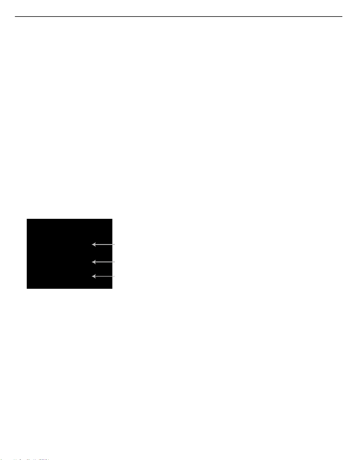
Color Bars
Gray Scale
100%
Black/White
Fields
26
HS300 harman/kardon
INITIAL SETUP
To change any of the video adjustments shown at the top of the screen,
use the Navigation Buttons to highlight the “+” to the right of a parameter name to increase the setting, or “–” to the left of a parameter name
to decrease the setting. Then press the Enter Button to change the value
as shown by the number of lines to the left or right of the center line in
the temperature bar for the parameter.
When only the dark center line is shown with no blue lines, the setting
is at the default midpoint value.
When adjusting the Black Level setting, only two adjustments are available:
“0 to 100” provides a full black level setting, which is indicated by the
bar at the midpoint
“7.5 to 100” or “full,” which complies with standards for video with
“setup”
Changes to any of the settings may be made with a test disc or broadcast signal playing, or you may use the internal test screen by using the
Navigation Buttons to highlight the word OFF next to the TEST SCREEN
line. Press the Enter Button and the setting will change to ON. A special
combination test screen, including both color bars and gray scale along
with 100% black and white fields, will be displayed. See Figure 46. To
recall the video controls, press the OSD Button. Navigate the settings to
make any necessary changes.
2. Adjust the contrast to the lowest level where you still can see all
bars within the gray scale in the test picture separately and clearly.
3. Adjust the brightness so that the bars in the gray scale are all
visible.The bar farthest to the left has to be as black as possible
rather than gray but the next gradation must clearly be distinct from
it. All the bars in the gray scale should be gradually and evenly
changing from black to white, left to right.
Contrast Adjustment
1. Adjust the contrast on your TV until you see a bright white bar in
the lower right corner of the screen and a deep-dark-black bar to
the left. The optimal contrast setting will depend on your preference
and the surrounding light in the TV room.
2. If the brightness of the white bar no longer increases when the
contrast is turned up or the borders of the white “harman/kardon”
letters on top bloom (overlight) into the black areas (drastically
decreasing the sharpness of the type), the contrast has been turned
up too much. Reduce the contrast until these effects disappear and
the video still looks realistic.
3. If you are watching TV with customary surrounding daylight, adjust
the contrast so that a normal video picture has about the same look
as the surroundings in your room. That way the eye is relaxed when
watching the TV picture. This contrast setting may be reduced when
the surrounding light is dimmed, thereby usually improving the
sharpness of a video significantly.
Figure 46 – Video Test Screen
With the test screen showing on your video display, the following
adjustments may be made:
• The proper color intensity setting on your TV.
• Proper color adjustments using the color bars, which should be
(left to right) black, white, yellow, cyan (turquoise), green, magenta,
red, blue, black.
• The proper color transition, seen as sharp separation of the bars.
• The performance of the color circuits in your TV (with “Video”
signals); bar edges should show no vertical crawling dots.
With the gray scale and the black/white fields below the color bars, the
brightness and contrast of your screen can be adjusted.
Brightness Adjustment
1. Turn down the color control on your TV until the color bars are
visible in black and white.
4. The gray scale in the middle line needs to have the same clear
difference between each bar as before the contrast adjustment.
If not, go back to “Brightness Adjustment” and repeat Step 3 and
then “Contrast Adjustment,” making only minor adjustments each
time for optimization.
Color and Tint Adjustment
1. When the brightness and contrast are set optimally, adjust the color
control to the level of your preference. Set the level where the colors
look strong but still natural, not overdone. If the color level is too
high, depending on the TV, some of the bars will seem wider or the
color intensity will not increase while the control is turned up. Then
the color control must be reduced again. Ultimately, you also should
test the color intensity with a video – e.g., pictures of natural faces,
flowers, fruit and vegetables, and other common natural articles for
an optimal setting of the color intensity.
2. Use the large white bar below the gray scale to tweak the warmth
of the picture. Every viewer has a preference as to how the glow of
the picture should be. Some prefer a little colder picture, some a
warmer glow. The Tint function and the white bar can be used to
control this.Adjust the Tint to the level where you feel the white
color has the tone you prefer.
Page 27

27
HS300 harman/kardon
INITIAL SETUP
Step Six – Configure Sources
This is the last step in the configuration process. It is necessary so
that the correct inputs are selected as you use various sources with
your HS 300.
NOTE: If you have not connected any devices to the TV or D-IN
input jacks on the HS 300, then you may skip this step. You are
now ready to begin enjoying the finest in home entertainment
using your HS 300 system. Turn to the Operation section to
learn how to make the most of the many features of the
HS 300.
Select the TV, AUX or D-IN source either by pressing its Source Selector
on the remote (see Figure 47), or by pressing the OSD button and
using the
the screen. See Figure 48 for the screen for the TV source.
‹/› Buttons to select the source from the list at the top of
Figure 49 – Digital Input (D-IN) Source Menu
Use the ¤ Button to select the Digital Input setting line, and press the
Enter Button to view the options of Coaxial or Optical digital audio input.
Select the input to which you have connected the source device you
wish to listen to, and press the Enter Button.
You may also select a surround mode for this source at the Audio
setting line, and you may adjust the volume level for this source at the
Level Adjustment setting line, but it is not necessary to make these
adjustments now.These settings only apply to the D-IN source.
Figure 47 – Source Selectors
Figure 48 – TV Source Menu
Press the Enter Button to access the TV menu settings, and use the
¤ Button to select the Audio Input setting. Press the Enter Button
to display the input options: Coaxial or Optical (digital audio) or Line
(analog audio). Use the
you connected your TV’s audio output, and press the Enter Button.
You may also select a surround mode for this source at the Audio
setting line, and you may adjust the volume level for this source at the
Level Adjustment setting line, but it is not necessary to make these
adjustments now.These settings only apply to the TV source.
‹/› buttons to select the input to which
You are now ready to begin enjoying the finest in home entertainment
with your HS 300 home theater system!
To configure the D-IN (Digital Input) source, use the Navigation Buttons
to highlight D-IN on the top line, and press the Enter Button to access
the settings for the D-IN source. See Figure 49.
Page 28
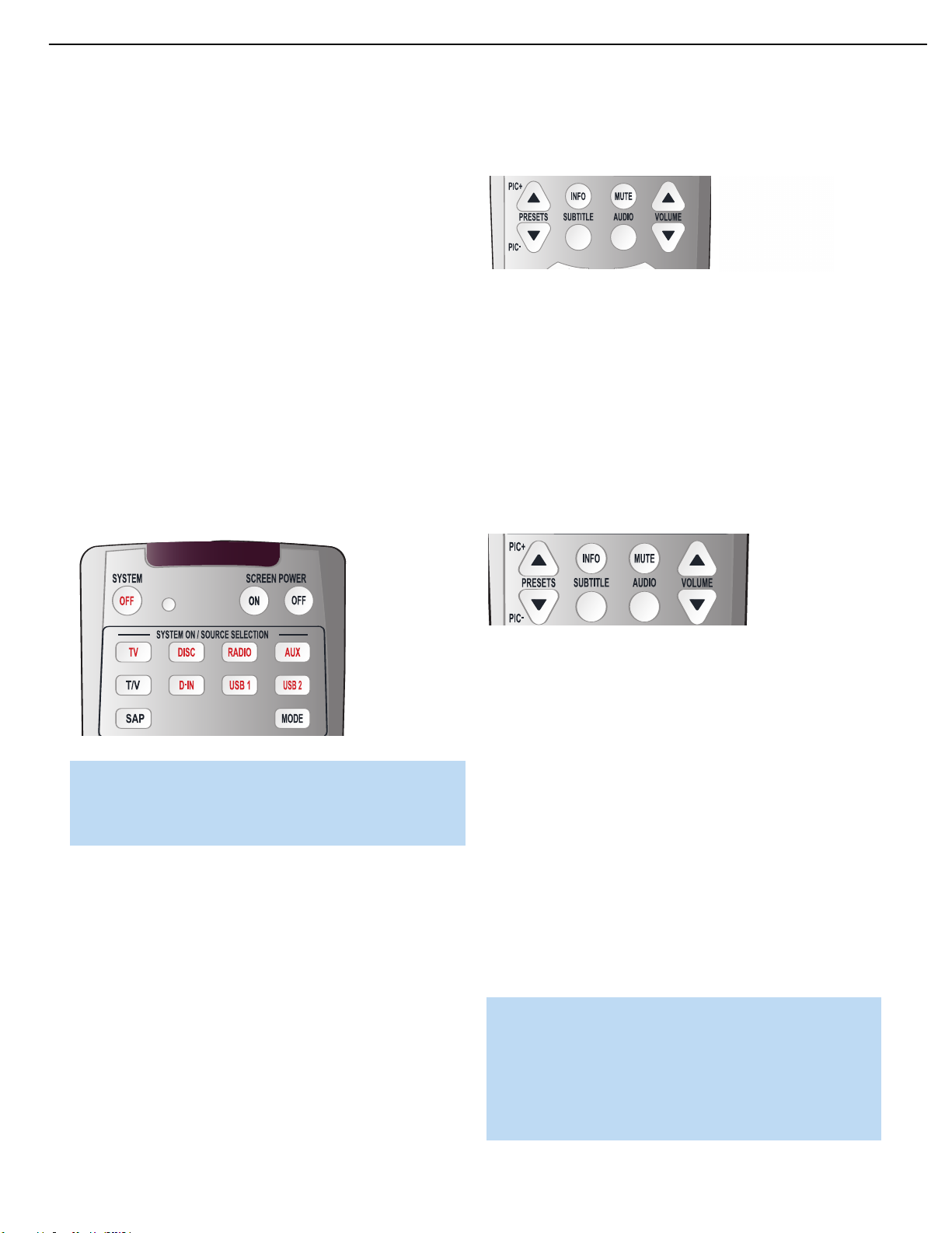
28
HS300 harman/kardon
OPERATION
Now that you have installed and configured your system components,
you are ready to begin enjoying your home theater system.
Turning On the HS 300
When you have plugged in the HS 300, the Power Indicator surrounding
the power switch should light up in amber. This indicates that the HS 300
is in Standby mode and is ready to be turned on. See Figure 50
Figure 50 – Power Indicator and Standby/On Switch
There are several ways in which the HS 300 may be turned on:
a) Press the Standby/On Switch on the top panel. See Figure 50.
b) Press the Open/Close Button on the top panel. See Figure 50.
c) Using the remote, press any one of these buttons: TV, DISC, RADIO,
AUX, D-IN, USB 1 or USB 2. See Figure 51.
audio materials, even 0dB may be too high, allowing for damage to
equipment.
Figure 52 – Volume Controls
The HS 300 is designed to reproduce audio with a minimum amount
of distortion. This clarity may lead you to think that your hearing and the
equipment can handle higher volumes.We urge caution with regard to
volume levels.
Mute Function
To temporarily mute all speakers and the headphones, press the Mute
Button on the remote. See Figure 53. Any recording in progress will not
be affected. The MUTE message will appear briefly in the display. To
restore normal audio, either press the Mute Button again, or adjust the
volume.Turning off the HS 300 will also end muting.
Figure 51 – Source Selectors
NOTE: Any time you press one of the remote’s Source
Selectors (i.e.,TV, DISC, RADIO, AUX, D-IN, USB 1 or USB 2),
the remote will switch modes so that it will transmit the codes
programmed to operate that device.
To turn the HS 300 off, press either the Standby/On Switch on the top
panel, or press the System OFF Button on the remote. See Figure 51.
When the HS 300 is unplugged, any settings you have programmed,
including system configuration and preset radio stations, will be
preserved for up to four weeks.
Volume Control
The volume may be adjusted either by turning the knob on the front
panel (clockwise to increase volume or counterclockwise to decrease
volume), or by pressing the Volume Control Buttons on the remote. See
Figure 52. The volume is displayed as a negative number of decibels
(dB) below the 0dB reference point. Unlike some volume controls on
other products, 0dB is the maximum volume for the HS 300. Although
it’s physically possible to turn the volume to a higher level, doing so may
damage your hearing and your speakers. For certain more dynamic
Figure 53 – Mute Button
Tone Controls
You may boost or cut either the treble or the bass frequencies by up
to 6dB.
The tone controls are adjusted using the Audio Setup submenu as
described in Step Two of the Initial Setup section.
Press the Setup Menu button on the remote, and use the Navigation
Buttons to highlight the Audio Setup menu icon on the left side of the
screen (has picture of a gear). Press the Enter Button to view the Audio
Setup menu, and use the Navigation Buttons to highlight the Tone
Control setting. To adjust the tone controls, the Tone Control setting
must be ON.The Bass and Treble controls may then be boost or cut
as desired. See Figure 42.
If you wish to remove the tone controls from the circuit for “flat”
response without losing bass or treble settings for future use, set the
Tone Control to OFF.
NOTE: The HS 300 does not have a conventional balance control.
The settings made using the Audio Adjustments submenu as
explained in Step Three of the Initial Setup section compensate
for any special acoustic characteristics of your room or speakers,
and we recommend that you leave the settings as they are after
you have completed the configuration process. It is possible to
manually adjust the levels of the left and right channels –
Page 29
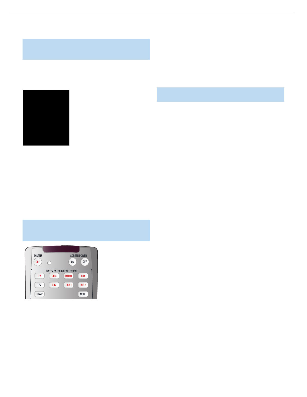
29
HS300 harman/kardon
OPERATION
decreasing one and increasing the other by the same amount –
using the Audio Adjustments submenu. This achieves the same
effect as using a balance control.
Headphones
Plug the 1/8" plug on a pair of headphones into the headphone jack
on the right side of the HS 300 for private listening.
Figure 54 – Headphone Jack
The HS 300 cannot accommodate a 1/4” headphone plug without
an adapter (not included). Using the headphones output mutes the
speakers.
Source Selection
Most of the time you may find it convenient to select a source by
pressing its Source Selector on the remote. See Figure 51.
The adjustment is called DVD Sound Mode for the Disc Player, and
is adjusted using the System Audio Setup submenu. There is no
surround sound processing available for materials on USB devices,
and they are always played in their original formats.
3. For the TV, AUX and D-IN sources, the HS 300 will adjust the audio
level (volume) for that source only, based on the setting in the
Source submenu.
NOTE: Pressing the Open/Close button always causes the
HS 300 to select the Disc Player as the source.
The following sections describe the operation of the internal disc player
and tuner, as well as the other sources.
Pressing a Source Selector not only selects that source as the HS 300’s
input, but also turns on the HS 300 if it is in Standby mode, and switches
the remote to the mode that operates the source.
NOTE: Press the Mode button on the remote to switch it to
operate another device without changing the source selection
for the HS 300. See Figure 55.
Figure 55 – Mode Button on Remote
When the source is selected, the HS 300 will make the following
selections as appropriate to the source:
1. For the TV and D-IN sources, the HS 300 will select the correct
analog or digital audio input. See Step Six of the Initial Setup
section for more information on configuring the audio input.
2. For all sources, the HS 300 will select the correct audio, or
surround sound, mode. The Audio Mode setting is adjusted using
the Source submenu for the RADIO, TV,AUX and D-IN sources.
Page 30

AUDIO/VIDEO
30
HS300 harman/kardon
OPERATION
USING THE HS 300 DISC PLAYER
Thanks to advanced digital technology, the HS 300 features an internal
DVD-Audio/Video disc player within its low-profile chassis.Although
you may previously have owned a CD or DVD player, we recommend
you take a few minutes to learn the specifics of operating the HS 300
disc player. You also may want to take a moment now to review the
glossary terms in the back of the manual to familiarize yourself with
the terminology used to describe DVD players.
Playback Basics
In some respects disc playback is the same for all types of discs.
We suggest you read through the basic instructions, and then read
the sections pertaining to the various disc types.
Disc Handling Precautions
• To keep the disc clean, handle the disc by its edge. Do not touch
the surface. See Figure 56.
Loading Discs
To load discs in the HS 300, first turn it on by pressing in the
Standby/On Switch or the Open/Close button on the top panel or the
DISC button on the remote.The Power Indicator is amber when the
unit is connected to an AC power source, and it turns blue when the
HS 300 is turned on.
Next, if you have not already done so, press the Open/Close Button so
that the disc tray opens.
Hold the disc by the edge, and gently place it into the disc drawer, making
certain that the disc is properly seated in the tray’s insert. If the disc is
not correctly centered, you may damage both the disc and the player
when the drawer closes.When loading discs, please note the following:
• The HS 300 will play discs with the following logos as well as
most DVD-RW or DVD+RW discs and most WMA and JPEG discs,
including Kodak Picture CDs, but not Kodak Photo CDs. DO NOT
attempt to play another type of disc.
Figure 56 – How to Handle a Disc
• Do not stick paper or tape on the disc. If there is glue (or a similar
substance) on the disc, remove the glue completely before using
the disc.
• Do not expose the disc to direct sunlight or sources such as hot air
ducts, or leave it in a car parked in direct sunlight, as there can be
a considerable rise in temperature inside the car.
• After playing, store the disc in its case.
• Do not write on the label side with a ball-point pen or other sharp
writing utensil.
• Be careful not to drop or bend the disc.
Disc Cleaning Precautions
• Before playing, clean the disc with a cleaning cloth. Wipe the disc
from the center out.
• Do not use solvents such as benzene, thinner, commercially available
cleaners or anti-static spray intended for vinyl LPs.
Disc Loading Precautions
• Do not load more than one disc on disc tray.
• Do not place a disc on the tray upside down.
• Do not try to close the disc tray when the disc is not positioned or
centered properly.
• The HS 300 will only display video in the NTSC format. Although the
PAL format is generally used in Europe and other regions of the world
outside North America, some music or other DVDs are available in
PAL with a Region Code of “0,” which means they may be played
on any DVD player around the world. The HS 300 will automatically
detect the PAL format, and make the necessary conversions so that
the video may be displayed on an NTSC TV. PAL discs bearing a
Region Code other than “0” or “1” may not be played on the
HS 300.
• Playback capability for CD-RW, DVD-RW, DVD-R, DVD+RW or
DVD+R discs will vary according to the quality of the disc. On some
occasions it is possible that these discs may not play on the HS 300.
This does not indicate any problem with the HS 300.
• The HS 300 will only play discs that are coded for Region 1 or discs
that are open to being played in all regions (Region Code “0”). Discs
that contain a Region Code of 2, 3, 4, 5 or 6 (as noted by a number
inside a world map logo on the disc’s jacket) will not play.
• Both 5-inch (12cm) and 3-inch (8cm) discs may be used.
Page 31

31
HS300 harman/kardon
OPERATION
• Load CDs or DVD-Audio discs, with the label side up.
• When loading DVD-Video discs with printed labels, load them label
side up. If the disc contains both standard and high-definition (not
HD-DVD or Blu-ray Disc) versions of the program, make sure the
desired label faces up.
• Some DVD-Video discs are double-sided. The title information for
these will be printed on the inner ring of the disc, very close to the
center hole.The title for the side you wish to play should be facing up.
After a disc is properly loaded, press the Open/Close Button to close
the disc drawer. After the drawer closes, you will see the READING message in the Main Information Display to alert you to the fact that the unit
is determining the type of disc (DVD-Video, DVD-Audio, CD, VCD, JPEG,
WMA or MP3) and is reading the data for track, chapter, title and other
information about the disc.
Once the disc’s data has been read, the type of disc will be displayed
by the Disc-Type Indicator in the front-panel display. If the disc is a DVD,
CD or VCD2.0 disc, it will automatically begin playing. The disc’s track
and timing information and other relevant data will appear in the Main
Information Display.
Any time a control button is pressed, an icon will appear in the upper
right corner of the screen to indicate the player’s action. These icons
include the standard transport modes (play, stop, pause, forward and
reverse fast and slow search, track skip), the opening or closing of the
disc drawer, or the prohibit icon (Ø) if the command action is not available at that time or for that disc.As explained in more detail below,
pressing the Status Button displays the Status Banner for DVDs, and
pressing the Info Button displays the Player submenu.
• VCD2.0 discs will begin play automatically, similar to a conventional
audio CD. Not all VCDs will play on the HS 300. VCDs containing raw
MPEG files will not play.
If a disc is already in the drawer when the unit is turned on, it will begin
playing. If the disc was stopped using the Resume function, playback
will begin from the point where it was stopped. If the disc was stopped
by pressing the Stop Button twice, the disc will begin playing from its
beginning. If the Disc Recognition feature was turned on in the System
Setup menu (see Figure 33), a screen will appear asking you whether to
begin playback from the beginning of the disc, or from the point where
playback was stopped during the last viewing session. See Figure 58.
Figure 58 – Disc-Recognition Resume Screen
Playback Features for DVD and CD Discs
See Figure 59 for reference to the transport controls described below.
• When a DVD is detected, playback will automatically begin and the
screen will show the program or the disc’s menu, depending on how
the disc was created.
• If a CD is detected, playback will begin automatically.
• If the disc contains MP3, WMA or JPEG files, or if it is a VCD without
playback control, the Player Information display will appear. See Figure
57. To play one of these files, use the Navigation Buttons to select a
folder and press the Enter Button to open it. Use the Navigation
Buttons to select a file for playback, and press the Enter Button to
begin play.
Figure 57 – Player Information Screen (JPEG/WMA Disc)
Figure 59 – Transport Controls
• To momentarily pause playback and freeze the current picture frame
on a DVD, press the Pause Button. To resume playback after pressing
the Pause button, press the Play Button.
• To move forward or backward through the tracks on a DVD-Audio
disc or CD, or the chapters on a DVD, press the Previous/Next
Buttons on the remote.
• To move forward or backward through the DVD or CD disc being
played at fast speed, press the Search Forward/Reverse Buttons.
Once one of these buttons is pressed, the fast search will continue
until the Play Button is pressed. Each additional press of the Search
Forward/Reverse Buttons will cycle through the five available fastsearch speeds.The speed will be indicated by the number of filled-in
triangles that appear in the upper right corner of the screen.
Page 32

32
HS300 harman/kardon
OPERATION
NOTE: Fast search is available when DVD-Audio, MP3 and
WMA discs are playing. Search speeds available may vary for
different types of discs.
• When a DVD is playing, you may move forward or backward through
the disc in slow motion by first pressing the Pause Button and then
pressing the Search/Slow Forward or Search/Slow Reverse Buttons.
Each additional press of the buttons will cycle the player through one
of the five forward or reverse slow-play speeds, as indicated by the
number of filled-in triangles appearing in the upper right corner of the
screen. Press the Play Button to resume normal playback.
NOTE:There is no audio playback during fast or slow-forward or
-reverse play. This is normal for DVDs, as surround processors
cannot process the digital audio streams during slow modes.
Slow-play is available for VCDs, but not for audio CDs, MP3s or
WMAs. Slow-play speeds may vary for different types of discs.
• To advance frame by frame while a DVD is playing, first press the
Pause Button, then press the Skip/Step (Previous) or Skip/Step (Next)
button repeatedly. Press the Pause or Play Button to resume normal
play. Frame-by-frame movement in reverse is not available.
NOTE: Playback of a disc with 96kHz/24-bit audio requires the
use of circuitry normally used for other features. Accordingly,
Slow Play Reverse and Step Advance features are not available
with these discs.
• When a camera icon appears on screen, or the Angle Indicator
appears on the front panel, it indicates that there is multiple-angle
information on the disc being played. To change the angle, press the
Angle Button repeatedly until the desired angle view appears.An onscreen banner message will appear to indicate the angle view in use.
• To illuminate the buttons on the remote control so that they may be
seen in low-light conditions, press the Light Button.
The availability of the Zoom, Repeat, Repeat A-B and Random functions
depends on the type of disc. In addition, the availability of the Player
Information screens and Status Bar vary from one disc type to another.
These features are described in the following sections describing playback of DVDs, CDs, MP3s, WMAs, JPEGs and VCDs. Programming
playlists is explained after the section on VCDs.
Page 33

33
HS300 harman/kardon
OPERATION
DVD PLAYBACK
Using a DVD’s Menu
One of the unique features of the DVD system is that it offers a producer the opportunity to include a wide range of features on a disc, including multiple language tracks; subtitles in a variety of languages; special
information such as movie trailers and cast information; and other customized information. In addition, producers may divide a movie or program into chapters that allow for quick access to specific parts of the
program. These chapters may be accompanied by thumbnail pictures of
a scene from the specific chapter to help you select the desired spot on
the disc.
When a disc is playing, press the Disc Menu Button to pause the playback and display the disc’s menu. As there are no hard rules about style
and contents for DVD menus, the way they appear on the screen and
the information they contain will vary from one disc to another. However,
the following general rules apply to most menus:
• You may move through the options on a menu with the Navigation
Buttons, as the disc’s programming allows. The option selected will
typically be highlighted in a certain color or inside an outline box.
• To select a highlighted option, which may either play a portion of the
disc or move to a submenu, press the Enter Button.
Zoom
The HS 300’s advanced digital video processing circuits include a
Zoom feature that allows you to enlarge the image of a DVD, VCD or
JPEG for closer examination of a particular part of the picture. Four
steps of enlargement are available.
Figure 60 – Zoom Button
• To use the Zoom feature, press the Zoom Button while a disc is
playing or paused. See Figure 60. Each press of the button will
increase the zoom-in effect. When you have zoomed through all
four steps (two steps of enlargement for VCDs), the picture will return
to normal size.
• When the zoom feature is activated, you may use the Navigation
Buttons to explore the enlarged picture once the information box with
the zoom ratio and playback time no longer appears on the screen.
• Some discs are created in a way that prevents the Zoom feature
from operating. In addition, the Zoom feature will not operate on disc
menus and may not operate on subtitles.
• On some discs, when you select the DVD menu during the playback
of a movie, the disc will return to the point in the program where the
menu was selected by offering a “Play Movie” option. Press the Enter
Button or Play Button to resume play. However, not all discs offer this
feature, and selecting the menu while playing a movie may mean that
you will have to go back to either the beginning of the program or the
start of a chapter. This feature is out of the control of the HS 300, as
it is set by the disc’s internal programming.
IMPORTANT NOTE ON DVD PLAYBACK
The HS 300 is capable of all the features and options covered
by the DVD standards. However, not all discs will function identically, and some discs will not have many of the features of the
DVD system. For example, most current DVD discs do not take
advantage of the multiple-angle feature.
When you press a button and the player displays the “Feature
Prohibited” icon “Ø”, this is an indication that the disc has not
been programmed for that feature. In addition, it is common for
the producers of DVD discs to block the use of certain functions
during only some parts of a disc. For example, many discs
prohibit the use of fast-play buttons or prohibit access to the
Chapter Menu display during the playback of copyright notices,
studio logos, movie credits or trailers.
Playback Resume
The HS 300 offers a “Resume” feature for DVD playback that is different from the conventional “Stop” function you may be used to on CD
players.When the Stop Button is pressed once, the disc will stop and
Resume will appear briefly in the upper right corner of the video screen
and in the Main Information Display. While the Resume feature is active,
the disc’s position is entered into the unit’s memory so that when the
Play Button is pressed to resume playback, the program will continue at
the point where it was when the Stop Button was pressed. To completely
stop playback, press the Stop Button twice.
You may resume a DVD (Audio or Video), CD, VCD with Playback
Control, MP3 or JPEG disc after placing the HS 300 in Standby mode.
Resume will not operate for WMA files or for VCDs that do not have
playback control.
Disc Recognition
When the Disc Recognition feature is turned on in the SYSTEM SETUP
menu, you may press the Stop Button either once (to enter Resume
mode) or twice (to enter Stop mode) and remove the DVD from the
player. Even if you turn the HS 300 off, the next time you insert that
DVD, you will be presented with the option of either starting playback
from the beginning, or resuming playback at the point at which you
stopped previously. The HS 300 can recognize up to 100 DVDs total.
Page 34

34
HS300 harman/kardon
OPERATION
Player Information Menu
The HS 300’s Player Information menu displays disc information and
enables you to program playback modes. Press the Info Button to
display the Player Information menu. See Figure 61.
Figure 61 – Player Information Screen (Info Button)
The Player Information menu has three submenus, which may be
accessed by using the Navigation Buttons to highlight the submenu’s
icon, and pressing the Enter Button to select it. These submenus are
different from the Setup menus in that many items are for display only
and cannot be changed using the menu system.
PLAYBACK INFO Submenu: This submenu displays basic disc and
playback mode information. See Figure 62. Access it either by pressing
the OSD button, or by highlighting the Info icon with the lower case “i”
(see Figure 61) and selecting it twice.
The top line shown in the contents section of Figure 62 is the current
title. Move the cursor to highlight this line and press the Enter button
to view a list of all the titles on the disc. Select any title and press Enter
to expand it and view the chapter list for that title. Select a chapter and
press the Enter button to begin play of that chapter.
The arrow(s) at the lower left of the screen enable you to advance forward or backward through the contents of the disc a page at a time.
PROGRAM submenu: The Program submenu displays the play order
of each title or chapter, depending on the current view, and allows you
to edit the order. See the section on Programming Play Lists below for
more information.
Figure 63 – Disc Info Submenu
DISC INFO Submenu: This submenu displays detailed information
about the disc content (see Figure 63). You will not be able to make any
changes to the items on this submenu. However, you may use the Video
Setup submenu to change the HS 300 player settings for video aspect
ratio or scan type.
Figure 62 – Player Information Screen (OSD Button)
Disc: This line displays the disc type, such as DVD-Video.
Audio: The current audio track will be displayed here. You may navigate
to this line, press the Enter button, and use the
through the available audio tracks, which are usually the available surround sound formats or audio languages. You may also change this
setting by repeatedly pressing the Audio button on the remote.
Playlist: This line indicates whether playback will occur in the disc’s
order, or following a programmed playlist.
Repeat: This line displays the current repeat mode, or Off if Repeat
mode is not active.
Random: Random play is not available for DVDs.
Subtitle: You may select from the subtitles available on the disc at
this line.
The disc’s contents are displayed below this basic information.
‹/› buttons to scroll
Disc: This line displays the disc type.
Disc ID: If the disc is encoded with an identification label, it will appear
here.
Aspect Ratio: This line displays the aspect ratio of the video content
on the disc, and the format in which it is being played back according to
the setting established in the VIDEO SETUP submenu. Some discs may
contain two versions of the same program with a widescreen aspect
ratio on one side of the disc, and a standard aspect ratio on the other.
Video Standard:
this will normally be NTSC, although some DVDs that are open region
(playable in all regions) may be in the PAL format. The HS 300 will
convert the video to the NTSC format used by your television.
Scan Type: This line displays whether the video program on the DVD
was recorded with a progressive- or interlaced-scan rate. It also displays
how the program is being played back, based on the setting established
in the VIDEO SETUP submenu.
Audio Resolution: This line displays the sample rate and bit rate for
the current audio format.
Audio Format: This line displays the current audio track, such as
Dolby Digital 5.1 or linear PCM.
The disc’s format is shown here. For Region 1 players,
Page 35

35
HS300 harman/kardon
OPERATION
Video Bit Rate: This line displays the video bit rate up to the maximum
of 10 Mbps.This indication will vary as a disc is played in response to
changes in the amount of compression that was applied to the video
signal when the disc was created. Thus, as shown in Figure 63, when
the disc is stopped or paused, this line will remain blank.
Audio Bit Rate: This line displays the audio bit rate up to the maximum
of 5 Mbps.
When you have finished viewing the Player menus, press the Info, OSD
or Clear Button to remove the displays from the screen and return to
normal play.
On-Screen Status Display
When a DVD is playing, you may press the Status Button at any time to
view a quick summary of the disc’s playback status.The Status Bar not
only gives you a snapshot of the unit’s current state, it also provides an
easy way to select a different group, title, chapter or track, or use the
time search feature. See Figure 64.
the time display options are Group Elapsed, Group Remaining, Track
Elapsed and Track Remaining.
Time Bar: This display is a graphic representation of the time elapsed
•
for the title being played. As the disc plays, the number of bars will
increase to reflect approximately what percentage of the title has been
played thus far.
Titles and Groups
To select a title or group, first press the Status Button so that the Status
Display appears.The Current Title or Group will be highlighted in a blue
box. Press the Enter Button and arrows will appear on either side of the
current title or group number, enabling you to either use the Numeric
Keys to enter the desired title/group or to use the
Buttons to scroll through the available title/group numbers. Press the
Enter Button again to begin playing the new title or group. See Figure 65.
‹/› Navigation
Figure 64 – Status Bar
• Group/Title: For DVD-Video discs, this displays the current title
number. For DVD-Audio discs, the group number is shown.
Chapter: For DVD-Video discs, this shows the current chapter.
•
For DVD-Audio discs, the current track is shown.
Play Mode Icon: This displays the current play mode icon;
•
e.g., Play
Time Display: This section of the display shows the time correspon-
•
ding to the type of display indicated in the Time Display Type.The
Time Search function enables you to start playback at any point in the
program. Use the
You may then use the Numeric Keys to enter the numbers corresponding to the time on the disc at which you wish play to commence.
After you enter the last digit, there will be a momentary delay before
the digit appears while the HS 300 locates the selected time position,
then play will begin.
Time Display Type: This section identifies the type of information
•
in the Time Display section of the display. Use the Navigation Buttons
to select this setting, and each subsequent press of the Enter Button
will change the time display from Title Elapsed, to Title Remaining,
to Chapter Elapsed to Chapter Remaining, and cycle back to Title
Elapsed. The time displayed on screen and in the front-panel
Information Display will change accordingly. For DVD-Audio discs,
›, Pause ±, Stop Í.
‹/› Navigation Buttons to highlight this display.
Figure 65 – Selecting a Title
If a “ø” icon appears when you attempt to select a new title (group),
this is an indication that the disc does not allow the title (group) to be
changed in this manner, even though a list of numbers will appear. This
is a function of the way the disc was created and is not a flaw in the
HS 300.
For some discs, you may press the Title or Audio Button during playback
to change the current title or group. Other discs will switch to the disc
menu, and some discs may simply restart play from the beginning of the
current title or group.This is a function of how the disc was authored,
and does not reflect a problem with the HS 300.
Chapters and Tracks
To select a chapter for DVD-Video discs or a track for DVD-Audio discs,
first press the Status Button so that the Status Display appears. Next,
press the
Number is highlighted. Press the Enter Button and arrows will appear on
either side of the current chapter or track number, enabling you to either
use the Numeric Keys to enter the desired chapter/track or to use the
‹/› Navigation Buttons to scroll through the available chapter/track
numbers. Press the Enter Button again to begin playing the new chapter
or track.
To select a specific chapter or track on a DVD at any time during playback, simply press the number corresponding to the chapter or track
you wish to view using the Numeric Keys.You may also move one by
one through the chapters or tracks at any time by pressing the Skip
Reverse (Previous)/Skip Forward (Next) Buttons.
› Navigation Button so that the Current Chapter or Track
Page 36

36
HS300 harman/kardon
OPERATION
Audio Soundtracks
Many DVDs contain more than one audio soundtrack. On many discs,
you will find multiple languages, while others will offer a choice of different audio formats or mixes (e.g., Dolby Digital or DTS), while some will
also contain commentary from the director or stars. The default audio
language is set in the Audio Setup menu.
To change the audio soundtrack, press the Audio Select Button to
display the Audio banner and show the current audio soundtrack
configuration. See Figure 66.
Figure 66 – Audio Status Bar
Each press of the Audio Select Button will change the current audio
soundtrack. Alternatively, press the Enter Button to enable you to scroll
through the choices of available soundtracks. See Figure 67.
Setup menu for the disc currently being played. The unit will
revert to its default setting with the next disc.
Subtitles (DVD-Video Discs Only)
Many DVDs contain one or more subtitle languages.The default subtitle
language is set in the System Setup menu, but you may also turn the
subtitles on or off, or change the language at any time during a disc’s
playback. To change the subtitle language or turn the subtitles on or off,
press the Subtitle Button to display the Subtitle banner and show the
current configuration. Each press of either the Subtitle Button will
change the current subtitle language, or turn subtitling off. Or you may
press the Enter Button and scroll through the available choices.When
your desired selection appears, press the
‹/› Navigation Buttons until
Done is highlighted and then press the Enter Button to remove the
banner display and return to normal playback.
NOTE: Due to the variations in how DVD discs are authored,
subtitle languages displayed by the HS 300 may not accurately
reflect the actual languages available on the disc. It is recommended that subtitles be selected using the disc’s menu.
Angles (DVD-Video Discs Only)
Some DVDs contain multiple-angle views, which allow the disc’s creators
to provide different camera views of the same scene. In many cases
the disc will alert you to the presence of multiple angles by showing a
camera icon or other indication, but in any case where multiple-angle
material is available, if the Show Angle Icon setting in the System Setup
menu has been set to On, the Multiple Angle Icon will appear on screen
briefly at the beginning of the passage where multiple camera angles
are available, and the Angle Indicator will light in the front panel
Information Display for the entire duration of the passage.
Figure 67 – Selecting an Audio Track
When the desired selection appears, press the ‹/› Navigation Buttons
so that Done is highlighted, and then press the Enter Button to remove
the banner display and return to normal playback.
NOTES ON AUDIO TRACKS:
• Not all discs contain multiple audio soundtrack choices.
Check the information on back of the disc jacket to see what
audio languages or format options are available.
• Some DVDs do not allow direct selection of the audio track
during playback. For these discs, you must change the audio
soundtrack using the disc’s menu system. Press the Disc Menu
Button to display the disc’s menu and then use the Navigation
Buttons to make your selection following the navigation scheme
of the individual disc.
• When you change the audio soundtrack or language with the
Audio Select Button on the remote control as shown above, you
only override the audio language setting established in the Audio
If the Show Angle Icon setting has been set to Off, neither the on-screen
nor front-panel icons will appear at any time, although you may still
change the camera angle as described below if you are familiar with the
presentation.
When multiple angle views are available, press the Angle Button to
change the view. See Figure 68. The current angle number and total
available angles will be displayed in the upper right corner of the screen.
Each press of the Angle Button will change the current camera angle.
Wait a brief moment for the angle status bar to disappear from view on
its own. If you press the Angle Button during a section where multiple
views are not available, the prohibit icon will appear.
Figure 68 – Angle Button
Page 37

37
HS300 harman/kardon
OPERATION
Repeat Play
The HS 300 offers several repeat functions that allow you to take
advantage of the capacity of the unit for unattended playback. Press the
Repeat button once to display the Repeat/Random Status Bar on-screen.
See Figure 69. Press the Repeat Button again to cycle through the
options, or press the Enter Button and scroll through the options:
Figure 69 – Repeat/Random Status Bar
• Repeat 1: Repeats the DVD chapter or DVD-Audio track currently
being played until the disc is manually stopped. The Repeat (“Rep.”)
and 1 indicators will light in the front-panel display.
Repeat Title or Group: This mode repeats the title or group currently
•
being played until the disc is manually stopped. The Repeat (“Rep.”)
indicator will light in the front-panel display.
A-B Repeat Play
The Repeat A-B function allows you to select any portion of a DVDVideo disc and have it repeat continually until stopped.
To initiate a Repeat A-B playback sequence, follow these steps while
a disc is playing:
Figure 70 – A-B Repeat Button
1. Press the A-B Repeat Button (see Figure 70) on the remote when
you want to choose the beginning point; the Status Bar will appear
on screen, and “REPEAT A-” will appear next to the playback mode
indicator. The “A” indicator will light in the front-panel display.
2. Press the A-B Repeat Button again to choose the end point. Repeat
A-B has been set, and the A-B section will be played continuously.
3. Press the A-B Repeat Button on the remote again to cancel Repeat
A-B mode.
Page 38

38
HS300 harman/kardon
OPERATION
CD PLAYBACK
Many functions of the HS 300 operate the same way for CD playback
as for DVD play; however, there are some important differences.When
a CD is loaded, the HS 300 will automatically display the Player
Information menu. See Figure 71. Status banners are not available during CD play. Features unique to CD play are described in this section.
Figure 71 – CD Player Information Screen
Player Information Menu
The HS 300’s Player Information menu displays disc information and
enables you to program playback modes. If it is not already on screen,
press the Info Button to display the Player Information menu. See
Figure 71.
Time Search Function: While the disc is in Play mode, you may begin
playback from a specific time in the track or disc by navigating until the
time is highlighted. Use the Numeric Keys to enter the desired start time,
remembering to enter leading zeros. For example, if you wish to begin
play at one minute and thirty seconds into the current track, enter “0-01-3-0.” After you enter the last digit, there will be a momentary delay
before the digit appears while the HS 300 locates the selected time
position, then play will begin.
Track List: A list of tracks on the disc will appear. Use the Navigation
Buttons to scroll through the list. Press the Enter Button or the Play
Button while a track is highlighted to begin play. If the disc contains
more tracks than there is room to display at once, a page down arrow
will appear in the lower left corner of the screen. Highlight it and press
the Enter button to view the next page of track listings. On subsequent
pages a page up arrow will also appear.
The Player Information menu has two submenus, Playback Info and
Program, which may be accessed by using the Navigation Buttons to
highlight the submenu’s icon, and pressing the Enter Button to select.
Playback Info Submenu: This submenu displays basic disc and
playback mode information. See Figure 71.
Disc: This line displays the disc type, such as CD.
Audio: This line displays the type of audio recorded on the disc, usually
Stereo for CDs.
Playlist: You may choose to play the tracks in order as they appear on
the disc, or you may program a playlist containing some or all of the
tracks in the order in which you wish to hear them. This line indicates
which of these two modes has been selected.
Repeat: With this line highlighted, press the Enter Button or the Repeat
Button to activate Repeat mode. Each press will change the repeat
mode from Repeat 1 (repeat one track) to Repeat All (repeat all tracks
on the disc) to Repeat Off. Repeat A-B is not selected using this setting.
Random: With this line highlighted, press the Enter Button or the
Random Button to activate Random play mode, in which the tracks on
the disc are played in random order. Each press will toggle between
turning Random play on or off.
Figure 72 – CD Program Screen
Program Submenu: This submenu lets you program a playlist. See
Figure 72. It looks similar to the Player Information submenu, but adds
a column to the right of the track list for indicating the play order. See
the section on Programming a Play List for more information. When you
have finished viewing the Player menus, press the OSD or Clear Button
to remove the displays from the screen.
Tracks
To select a track, make sure the Player Information menu is on screen.
Press the Info or OSD Button to activate it if necessary. Next, press the
Navigation Buttons so that the Track is highlighted, and press the Enter
Button to begin playing the new track.
During playback, you may move one by one through the chapters at
any time by pressing the Skip Reverse (Previous)/Skip Forward (Next)
Buttons.When you press the Previous or Skip Reverse button once, the
player will return to the start of the current track. Additional presses of
either button will step back through the available tracks, one at a time.
See Figure 73.
Time: This line indicates the time display mode (Track Elapsed, Track
Remaining, Disc Elapsed, Disc Remaining), with the time displayed to
the right. Press the Enter Button to enable scrolling through the time display options, and press the Enter Button again to make your selection.
Figure 73 – Skip Reverse (Previous) and Skip Forward (Next) Buttons
NOTE: When a JPEG, MP3 or Windows Media disc is playing, a
special screen will appear. See the section describing those
types of discs for more information.
Page 39

39
HS300 harman/kardon
OPERATION
Repeat Play
The HS 300 offers several repeat functions for CDs that allow you to
take advantage of the capacity of the unit for unattended playback:
Repeat Program: Repeats the current playlist if Programmed Order
•
has been selected at the Playlist setting.
Repeat 1 Track: For CDs, VCDs, MP3s and WMAs, repeats the track
•
or file currently being played until the disc is manually stopped. The
Repeat and 1 indicators will light in the front-panel display.
Repeat Disc: For CDs, VCDs, MP3s, WMAs and JPEGs, repeats the
•
entire disc until play is manually stopped. The Repeat indicator will
light in the front-panel display.
Repeat Folder: For MP3s, WMAs and JPEGs, repeats all tracks with-
•
in the current folder until play is manually stopped. The Repeat indicator will light in the front-panel display.
Repeat A-B: Repeats any selected portion of the disc until the disc
•
is manually stopped (see below for more information).
Each press of the Repeat Button (see Figure 74) cycles through the
available Repeat options (except Repeat A-B). In addition, the Repeat
setting in the Player Information menu will change.
Random Play
The Random Play function will play all of the tracks on a CD in a
random order, as selected by the HS 300. Once the HS 300 has
played all of the tracks on the disc once, it will stop.
Select the random mode by pressing the Random Button on the
remote. See Figure 75. Each press of the Random Button will toggle
the setting between “Off” and “On”, meaning that the remaining tracks
on the disc will be played in random order.
The Random Indicator in the Front-Panel Information Display will light
when the Random setting is on.
Figure 75 – Random Button
Figure 74 – Repeat Button
A-B Repeat Play
The Repeat A-B function allows you to select any portion of a CD and
have it repeat continually until the unit is manually stopped.
To initiate a Repeat A-B playback sequence, follow these steps while
a disc is playing:
1. Press the A-B Repeat Button on the remote (see Figure 70) when
you want to choose the beginning point; the Repeat A- icon appears
on the Repeat line of the Player Information menu to indicate the
beginning of the passage to be repeated.
2. Press the A-B Repeat Button again to choose the end point. Repeat
A-B has been set, and the A-B section will be played continuously.
3. Press the A-B Repeat Button again to cancel Repeat A-B mode.
Page 40

40
HS300 harman/kardon
OPERATION
MP3, WINDOWS MEDIA AND JPEG PLAYBACK
The HS 300 will recognize data on CD-ROM discs and USB devices
recorded in the MP3, Windows Media 9 (WMA) or JPEG formats,
including images stored on Kodak
discs with more than one of the three formats.
The specific file types that may be played on the HS 300 are:
•
MP3 Files: MP3 is a popular audio compression format that was
developed by the Motion Picture Experts Group as part of the MPEG1 video compression format. Depending on the specific MP3 encoder
used, file size is greatly reduced so that you store many more songs
on one compact disc than in the standard audio CD format. MP3 is
also used to download audio files to computers for home use. In
order to play an MP3 file on the HS 300, the disc may not contain
any encryption or coding that prevents playback. Always be certain
that you have, or have purchased, the proper rights or authorization
before creating a CD-ROM with MP3 or any other codec format.
WMA Files: WMA (Windows Media Audio) is an audio compression
•
format developed by the Microsoft
Windows Media Player. WMA files may be created with greater
compression than MP3 without sacrificing audio quality so that even
more songs may be recorded on a disc.There have been a number
of versions of Windows Media, and the HS 300 is compatible only
with files that end in the “wma” extension and that were recorded
using the Windows Media Series 9 encoding, but only up to 320kbps.
®
Picture CDs.You may also play
®
Corporation for use with its
MP3 or WMA Disc Playback
MP3 and WMA discs may contain 200 tracks or even more. To get the
best overview about all tracks on the disc and their names and to select
them comfortably, use the on-screen display rather than the front-panel
display. The front-panel display will only show the number and the
elapsed time of the track being played.
The supported bit rate for WMA files is between 64kbps and 320kbps.
The supported bit rate for MP3 files is between 32kbps and 320kbps.
• To select a folder (if any), press the Navigation Buttons until the
desired folder name is highlighted, then press the Enter Button.
• To select a track, press the Navigation Buttons until the desired track
name is highlighted.
To start play of the selected track, press the Enter or Play Button.
During MP3/WMA playback, some of the standard CD/DVD playback
controls operate in their normal fashion (refer to Figure 59):
• You may skip forward to the next track on the disc by pressing the
Skip/Next Button.
• You may skip back to the previous track on the disc by pressing the
Skip/Prev Button
• Press the Pause Button to momentarily stop playback. Press the Play
Button to resume play. Press the Stop Button to enter stop mode.
twice.
JPEG Files: “JPEG” is the acronym used to identify image files
•
recorded according to specifications established by Joint
Photographic Experts Group for compressing still images. Identified by
the file extension “jpg” when they are recorded on most computers,
JPEG files may be created by a digital still camera and then edited
and “burned” to a disc in your personal computer, recorded on a
CD-ROM disc from film images by a photo processor, or scanned
from printed photos into your personal computer and then burned
onto a CD-ROM. You may also connect a digital camera directly to
one of the HS 300’s USB ports, if the camera is equipped with a
USB connection, and if it stores its images in the JPEG format.
Discs containing MP3, WMA or JPEG files are navigated and controlled
a little differently from standard DVDs and CDs.When a disc containing
one or more of these types of files is loaded in the HS 300, the Player
Information menu screen will appear. See Figure 76.
Figure 76 – Player Information Screen
(JPEG/WMA Disc)
This screen will display a list of the main folders contained on the disc
The elapsed time will appear in the upper right corner of the screen. It
isn’t possible to change the time display, and the Time Search function
is not available.
• Press the Search Forward or Search Reverse buttons, for fast search
of a track. Press the Play
›, Pause ± or Stop Button Í to end fast
play.
• Slow-play is not available during MP3/WMA playback.
• You may play an MP3 or WMA disc in random mode by adjusting
the Random setting in the Player Information submenu. You may also
access the Random function while an MP3 or WMA disc is playing
by pressing the Random Button. See Figure 75.
• The Repeat function may be accessed during playback of an MP3 or
WMA disc by pressing the Repeat Button on the remote. See Figure
74. Repeatedly press the Repeat Button to scroll through the options
of Repeat 1 (repeat one file), Repeat All (repeat all files) or Repeat
Folder (repeat all files within the current folder). The next press will
turn the repeat function off. Repeat A-B is not available during
MP3/WMA playback.
NOTES ON MP3 AND WMA PLAYBACK
• During playback, the front-panel display and the time indicator
on the screen above the list will show the elapsed time of the
track being played. Other time display options are not available
with MP3/WMA playback.
• The HS 300 is only compatible with standard MP3- and
WMA-encoded discs. Other compressed audio formats used
for Internet audio downloads will not play on the HS 300.
Page 41

41
HS300 harman/kardon
OPERATION
• Due to the differences in various versions of the MP3 and
WMA formats, and the many differences between the CD-R
machines used to record discs on a computer, it is possible
that some discs may not play on the HS 300 even though
they will work on a computer. This is normal and does not
indicate a fault with the unit.
• When a multisession disc with both standard CD audio and
MP3 or WMA content is in use, the HS 300 will play only the
CD audio sections of the disc.Track numbers will be visible in
the display, but the files will not be decoded.
• If a disc containing MP3, WMA and/or JPEG files is created
in more than one session, the HS 300 may not recognize
files added during the later sessions, especially if the disc was
finalized after the first session.
• When a disc with multiple folders is playing, only tracks from
one folder can be displayed and played at a time. Select the
desired folder and press the Play Button or Enter Button to
start the first track. To see and play tracks from other folders,
you must first select the root folder using the Navigation
Buttons, and press the Enter Button to open or close that
folder. You may then navigate an open folder and select the
desired folder. Press the Enter Button to open the folder, and
select the desired track. Then press the Play Button.
You may view thumbnails of the images in the selected folder by pressing the Disc Menu Button. When the images appear on screen, you may
use the Navigation Buttons to move the picture frame until the desired
image is selected. Press the Enter Button to display a full-size view of
that image. See Figure 77.
Figure 77 – Thumbnail Image Menu
Simultaneous Playback
When MP3 audio files are stored on the same disc as the JPEG stillimage files, you may simultaneously play the audio and view the still
images.To access each set of folders, i.e., audio and still-image, select
both the Music and Picture icons on the left side of the screen. See
Figure 78. Each click on one of the icons selects or deselects the
relevant folders for listening or viewing. For WMA files, you may only
select one of the icons at a time, as simultaneous playback is not
available for JPEG and WMA files.
• Only stereo-audio playback is available for MP3 and WMA
discs.
• Programmed playlists are not available for MP3/WMA discs.
• Use the Navigation Buttons to select the DISC INFO Submenu
icon on the left side of the screen, and press the Enter Button
to view it. If the disc contains ID3 tag information, then the
current MP3 track information – song title, artist, album, year,
genre, and any comments – for WMA and JPEG files, only
the file name will appear.
JPEG Playback
The HS 300 is capable of recognizing JPEG still-image files and displaying them. When a disc or folder containing JPEG files is loaded, the
JPEG Disc-Type Indicator will light in the Main Information Display.The
disc will immediately begin displaying the images on the disc in order.
When viewing JPEG images, the Angle Button may be used to rotate
the image.With the image onscreen, press the Angle Button once to
display the current orientation of the image, usually +0. Press the Angle
Button again to rotate the image clockwise 90 degrees. Each additional
press of the Angle Button will continue to rotate the image clockwise by
90 degrees.
You may use the Zoom Button to enlarge a JPEG image, and the
Navigation Buttons to explore the enlarged image.
Figure 78 – Simultaneous Playback
NOTE: High-resolution images may not display correctly during
simultaneous playback due to the HS 300’s memory limitations.
Slide Shows
If several JPEG still-image files are available in the selected folder, the
HS 300 will display them in turn automatically as a “slide show.” You
may program the amount of time each still image remains on screen
using the Picture setting in the Player Information menu. See Figure 79.
Select from a viewing time of 15, 30 or 45 seconds, or when simultaneous playback with MP3 audio files is desired, you may program the
HS 300 to synchronize display of the still images to the audio track by
selecting the Follow Audio Track option.
Figure 79 – Picture Viewing Time
Page 42

42
HS300 harman/kardon
OPERATION
VCD PLAYBACK
VCD, a video-playback format that predates DVD, is based on a different
compression format than DVD and uses a recording method that is
similar to CD. Although the DVD has, for the most part, replaced VCD
as a format, the HS 300 offers VCD playback so that you may play your
existing library of VCD discs, or home movies that you have recorded
as VCDs on your computer.
There are two versions of the VCD format: an early version which is
simply called “VCD” and a later version with Playback Control that’s
called “Version 2.0” or “PBC.” The HS 300 is compatible with both
forms of VCD, although playback will vary according to which version
is used and the specific way in which the disc was created.
Even though VCD discs provide video, because the format is based on
CD technology, the playback functions for a VCD disc are similar to CD.
To play a VCD disc, place it in the HS 300 as you would do with any
other CD or DVD disc.The unit takes a few seconds to read the disc’s
contents; the VCD Disc Type Indicator in the front-panel display will light
and the disc will begin playing.
Keep in mind that the exact level of functionality for any VCD will vary
widely and it is ultimately determined by the way the disc was created,
not by the HS 300, particularly if the disc has been created under VCD
Version 2.0 with Playback Control (see “Playback Control”).
NOTE: VCDs that contain only raw MPEG files will not play in the
HS 300.
When playing VCD discs, most standard DVD/CD playback controls are
used, including Play, Stop, Pause, Resume, Track Skip Forward and
Reverse, Slow Forward, Step Forward and Fast Forward. The Reverse
Search and Step Reverse functions are not available with VCDs.
DVDs.The elapsed time will appear as a graphic temperature bar, with
additional lines added as more of the track or disc is played.
Figure 80 – VCD Status Bar
Zoom
The Zoom function is available for VCDs by pressing the Zoom Button.
Repeatedly pressing this button will cycle through the possible settings of
1x, 2x and 3x zoom, as shown in the upper right corner of the screen.
After the enlargement indication disappears from view, you may explore
the image using the Navigation Buttons.
Playback Control
VCD discs made under the Revision 2.0 specification will usually offer
PBC playback control. The PBC Indicator in the front display will turn on
automatically with any VCD when the disc is played. With PBC, you can
select titles and navigate the disc as with DVDs. However, the access to
some functions may be prohibited by PBC playback control; in that case,
the prohibit icon will appear on screen.
When a VCD is made without PBC, the disc can be controlled the
same as an audio CD, but direct track access by entering a number
is not possible without opening the Status Bar. With PBC, many discs
include chapter selection menus that are similar to those found on
DVDs. However, on VCD discs, the disc menu (if any) is accessed and
controlled differently than on DVDs.
• Play will start with the first track (which may be an intro), then proceed
to the VCD menu (if any) automatically.
With VCDs, you have access to information on the disc playing by
pressing the Info Button on the remote.The availability of the Repeat
and Random functions will depend on whether PBC Support has been
activated using the System Setup Submenu. With PBC Support on,
Repeat and Random will not be available.
Repeat A-B is always available. Simply press the Repeat A-B Button
once at the beginning of the passage to be repeated, again at the end
of the passage, and a third time to cancel Repeat A-B mode.
Status Bar
When playing VCD discs, it is possible to access the disc’s features
using the Status Bar. Press the Status Button to view it.
The Status Bar will appear the same as for DVDs (see Figure 80),
except that the current track number will be shown, rather than the title,
and there is no chapter display. You may select the track number and
change it to skip to another track. You may also begin play from a
specific time marker by selecting the numeric time display and entering
the desired starting point using the Numeric Keys.You may also change
the time display from Track Elapsed, to Track Remaining, to Disc
Elapsed, to Disc Remaining, and back to Track Elapsed, just as with
• The Next (Skip Forward) command will skip to the VCD menu from
the intro (Track 1) directly.
• Once the menu options appear on the screen, make your selection
by pressing the Numeric Keys that correspond to your desired choice.
The desired selection will begin playing automatically.
• Direct number entry without any VCD menu shown on-screen has no
effect – even when the Status Bar is on.
The Disc Menu Button used during DVD playback is not used for VCD
playback. Use of functions when PBC is on will vary according to the
disc type. Note that if the disc was created with Playback Control (PBC)
it is not possible to change track numbers directly.
Page 43

43
HS300 harman/kardon
OPERATION
PROGRAMMING A PLAYLIST
You may program a playlist for any type of disc except for VCDs by
following these steps:
1. If the disc is playing press the Stop button. Playlists may only be
programmed in Stop mode.
2. If the Player Information screen is not visible, press the OSD button
to display it. Make sure to press the Program icon on the left side of
the screen so that you may view the column indicating the play order
of the tracks, chapters or titles. Navigate until the Disc List setting is
highlighted. See Figure 81.
Figure 81 – Program Submenu
Figure 83 – Adding a Track to the Playlist
5. Repeat Step 4 to add as many tracks as you desire to your playlist.
You need not add all tracks on the disc.
NOTE: If you select a track that was already added to the playlist and add it again, it will not repeat. Instead it will be moved
to the end of the playlist. If you wish to repeat a track during
programmed play, use the Repeat functions.
6. Navigate to the Disc list column heading and select the Prg list option
to view the tracks in programmed play order. You will notice that the
tracks have automatically been reordered, and that any gaps in the
play order have been filled. See Figure 84.
3. Press the Enter Button and select the Clear Program option, which
clears all tracks from the playlist. See Figure 82.
Figure 82 – Clearing Play-Order List
4. The simplest way to program your playlist is to scroll down to each
track in the desired playlist order. Press the Enter Button and select
the Add option. Remember to stay in the Play Order column. If you
press Enter while the track name is highlighted, the HS 300 will
simply play that track.
See Figure 83, in which the user scrolled to Track 5 in the list, pressed
the Enter Button to program it, and selected the Add option. Track 5
was automatically programmed as the next track in the playlist. Since
the playlist was empty, Track 5 was programmed to play first.
Figure 84 – Programmed Playlist
7. To play your programmed play list, navigate to the Playlist setting near
the top of the screen. Select it, and choose the Programmed order
option. See Figure 85.
Figure 85 – Playlist Setting
Page 44

44
HS300 harman/kardon
OPERATION
Alternatively, press the Playlist Button to toggle the Playlist setting
between Disc and Programmed order. See Figure 86.
Figure 86 – Playlist Button
9. Press the Play button to begin play.
Editing a Programmed Playlist
You may edit your playlist by following these steps:
1. If the disc is playing press the Stop button. Playlists may only be
programmed or edited in Stop mode.
2. If the Player Information screen is not visible, press the OSD button
to display it. Make sure to press the Program icon on the left side of
the screen so that you may view the play order column, and navigate
until the Prg List setting is highlighted. See Figure 87. Select it and
change it to the Disc List option so that you may view all tracks on
the disc.
d) If you wish to add a track that was not previously programmed
into your playlist, then scroll to its play order number, select it and
program it into the list using either option a) to add it to the end of
the list or option b) to program it to a specific place in the list. See
Figure 89.
Figure 89 – Adding a New Track to an Existing Playlist
Canceling A Programmed Playlist
If you wish to play the tracks in the original order in which they appear
on the disc, navigate to the Playlist setting and select the Disc’s order
option. Your playlist will be saved, and you may play the tracks in
programmed order by changing the Playlist setting.
To clear a programmed playlist from the HS 300’s memory, follow one
of these procedures:
Figure 87 – Viewing a Programmed Playlist
3. Scroll to the play order number for the track you wish to edit, and
select it. See Figure 88.
Figure 88 – Editing a Track Within a Playlist
a) To move the selected track to the end of the playlist, select the
Add option.
b) To move the selected track to a different position in the playlist, scroll
to the option that shows three dashed lines. Use the Numeric Keys to
enter the desired order in the playlist, and press the Enter button.
1. Navigate to the heading of the play-order column (either Disc list or
Prg list) and select it. Choose the Clear Program option.
2. Open the disc drawer. When you close it, even if the same disc is
loaded, the playlist will have been cleared.
c) To delete the track from the playlist, select the Clear option.
Page 45

45
HS300 harman/kardon
OPERATION
USING THE HS 300 TUNER
Select the HS 300 tuner as the source either by pressing the RADIO
button on the remote, which will also turn on the system if it is in
Standby mode, or by pressing the OSD button to access the menu for
the current source. Use the
and press Enter to select it. The Radio screen will appear as shown in
Figure 90.
Figure 90 – Radio (Tuner) Screen
The screen contains the following information:
AUDIO: This setting is used to select the audio surround mode.
STATION NAME: If you have selected the RDS (Radio Data Service)
display by selecting its icon on the left side of the screen, this line will
display any identifier transmitted by the radio station. Press the RDS icon
to deselect it and remove the Station Name line from view.
#: The HS 300’s tuner includes a total of 60 preset station locations,
30 for each band (AM or FM), which may be viewed on screen. The
numeric column on the left side of the station list indicates the preset
number for each station. The first time you select the tuner as the
source you will see a default list of presets. Most likely these stations
are not in use in your area. You may select the # symbol at the head
of this column and you will be presented with the following options
(see Figure 91):
Auto Preset: Select this option to have the HS 300 automatically
scan for stations with acceptable signal strength. Each station found
will be added as a preset.
Clear List: Select this option to clear the list of presets.
Restore Default List: Select this option to reset the presets to
the factory default list.
‹/› Navigation Buttons to highlight RADIO
Station: The Station column lists your preset stations by name. Press
the Enter Button to listen to the highlighted station, and press the Enter
Button again when the proper name of the station is shown on the
Station Name line to capture the station’s name, if it is being transmitted
as an RDS signal and if you have selected RDS display using the icon.
Frequency: Unlike other tuners you may have used previously, the
HS 300 is tuned using the preset locations. You may select a preset
station to listen to as described above, or you may tune a new
frequency for that preset using the Frequency column.
NOTE: Changing the frequency so that you may listen to a different station permanently changes the preset for that location.
If you wish to listen to a new station, we recommend that you
scroll down to an unused preset location, or one which you
don’t wish to listen to before tuning to a new frequency.
To tune a new frequency:
1. Highlight the frequency of an unused preset, or a preset you no
longer wish to save.
2. Tune to the new frequency in one of three ways:
Auto Tuning: If the Tuning icon on the left side of the screen is
depressed so that the word AUTO appears, then the tuner is in auto
tuning mode. Use the Forward or Reverse Search/Slow Buttons on
the remote (see Figure 92) to scan to a higher or lower frequency.
Press the Search Button once, and the tuner will scan until it finds a
station of acceptable signal strength. To stop scanning without finding
such a station, press the opposite-direction Search Button.
Figure 92 – Tuning a Radio Station
Manual Tuning: If the Tuning icon on the left side of the screen is
deselected so that the word MANUAL appears, then the tuner is in
manual tuning mode.The HS 300 defaults to auto tuning mode;
thus you may find it necessary to select manual tuning mode first.
Use the Forward or Reverse Search/Slow Buttons on the remote
(see Figure 92) to tune to a higher or lower frequency by one
frequency increment at a time (0.1MHz for FM, or 10kHz for AM).
Direct Tuning: If you know the frequency of the station you wish
to listen to, use the Numeric Keys to enter it, and it will be tuned
immediately. You must enter digits for all places in the frequency for
it to be accepted; e.g., if you wish to tune to station 92.3 FM, enter
9 – 2 – 3 – 0.
Figure 91 – Programming Presets
To switch between the AM and FM bands, navigate to the tuner band
selector icon on the left side of the screen. Press the Enter Button until
the desired band appears on the icon. Alternatively, press the Radio
button on the remote repeatedly to toggle between the bands.
Deselect the Info icon on the left side of the screen to remove the
Audio and Station Name lines from view, enabling you to view a few
more presets at a time on screen.
Page 46

46
HS300 harman/kardon
OPERATION
Select a preset station by following one of these steps:
1. With the cursor anywhere on the screen except in the Frequency
column, use the Numeric Keys to directly enter the desired preset
number, and press the Enter Button to begin listening to that station.
Remember to first select the desired tuner band.
2. With the cursor anywhere on the screen use the Preset Buttons on
the remote to scroll through the list of stations.The Preset Up Button
will navigate to a higher-numbered preset, and the Preset Down
Button navigates to a lower-numbered preset. However, the cursor
will appear to travel in the wrong direction, as the preset stations list
is numbered in increasing order down the screen.
3. With any station highlighted, use the
scroll through the list of presets, and press Enter to tune the highlighted station. Use the Navigation Buttons to highlight the large Page
Up and Page Down icons when visible on the left side of the screen.
Each press of either icon will skip one page of preset stations.
NOTE: Be aware that the screen saver may not activate itself
when the tuner is in operation. After selecting the desired station,
you may wish to turn off your video display to avoid “burn-in.”
You will still be able to use the Search and Preset buttons, as
well as the Numeric Keys, to tune a new station or preset, which
will be displayed on the HS 300’s front panel.
⁄/¤ Navigation Buttons to
Page 47

47
HS300 harman/kardon
OPERATION
SELECTING AN EXTERNAL SOURCE
As explained in the Installation and Initial Setup sections, you may
connect the audio outputs of an external source device, such as a cable
television set-top box, to any of the HS 300’s analog or digital inputs.
You may select any one of the three source inputs: TV, AUX (Auxiliary)
or D-IN (Digital Input).
Select the source in one of two ways:
1. Press the correct Source Selector on the remote. If the HS 300 is
in Standby mode, this will turn it on.
2. Press the OSD button and use the
source in the list at the top of the screen. Press the Enter Button to
select the source, and its menu screen will be displayed. Press the
OSD button to clear the menu from view.
‹/› Buttons to highlight the
TV Source
When you highlight TV at the top of the screen, the screen shown in
Figure 93 will appear.
Figure 93 – TV Source Screen
Press the Enter Button to select TV as the source input, and to access
the menu settings.
Figure 94 – AUX Source Screen
Press the Enter Button to select AUX as the source input, and to
access the menu settings.
Audio: Use this setting to select a surround mode.
Level Adjustment: This setting allows you to adjust the volume
independently for this source.
NOTE: There is no setting for selection of the audio input for
this source. Only the Auxiliary analog audio input is available.
Press the OSD button to clear this menu from the screen.
Digital Input Source
When you highlight D-IN at the top of the screen, the screen shown
in Figure 95 will appear.
Audio: Use this setting to select a surround mode.
Audio Input: Use this setting to select either the Coaxial or Optical
Digital or TV Analog Audio input, depending on which input the TV
source device is connected to.
Level Adjustment: This setting allows you to adjust the volume
independently for this source.
Press the OSD button to clear this menu from the screen.
Auxiliary Source
When you highlight AUX at the top of the screen, the screen shown in
Figure 94 will appear.
Figure 95 – D-IN Source Screen
Press the Enter Button to select D-IN as the source input, and to
access the menu settings.
Digital Input: Use this setting to select either the coaxial or optical digital
audio input, depending on which input the source device is connected
to. If you have used the coaxial input for the TV source, then connect
the D-IN source device to the optical input, and select that input here.
Audio: Use this setting to select a surround mode.
Level Adjustment: This setting allows you to adjust the volume
independently for this source.
Press the OSD button to clear this menu from the screen.
Recording
Two-channel analog and digital audio signals are normally available at
the Coaxial Digital and Analog Audio recording outputs. Thus, to make a
recording, you need only make sure to connect your audio recorder to
Page 48

48
HS300 harman/kardon
OPERATION
the appropriate output jacks, insert blank media and make sure the
recorder is turned on and recording while the source is playing.
NOTES:
1. Analog audio signals are not converted to digital form, and
digital audio signals are not converted to analog audio form.
However, you may record a coaxial digital audio source using
the digital audio output.
2. Only PCM digital audio signals are available for recording.
Proprietary formats such as Dolby Digital and DTS may not
be recorded using the digital audio connection, although, if
the source is connected using the analog audio connections,
an analog recording may be made.
3. To activate recording using the HS 300 remote, if you have
programmed your recorder’s codes, press the title and subtitle buttons simultaneously.
4. Please make certain that you are aware of any copyright
restrictions on any material you record. Unauthorized duplication of copyrighted materials is prohibited by federal law.
USB Source
The HS 300 is equipped with two USB ports, located on the front right
side (USB 1) and the rear (USB 2) of the unit. See Figure 96.
Many of the elements of the screen are similar to the Disc Player
Information screen used to navigate CDs.
Disc: Identifies the type of files found on the device.
Time: The time appears in the upper right corner of the screen.
It is for display only, and the time-search function is not available.
Audio: This setting allows you to select a surround mode.
Playlist: This setting cannot be changed for USB devices, as
programmed play is not available.
Repeat: This setting allows you to repeat play of one track, one folder
of files or to turn off repeat play.
Random: Random play is not available for USB devices.
Picture: If there are JPEG still-image files stored on the device, you
may select the amount of time each remains on-screen – 15, 30 or 45
seconds.There is no option for simultaneous playback of JPEG and
MP3 or other audio files.
You may remove the above lines from view by highlighting the Info icon
on the left side of the screen. Pressing the Enter Button to deselect it.
Navigate the files stored on the device as you would the tracks on a
CD. Press the Enter Button to expand or collapse a folder, and use the
⁄/¤ buttons to scroll through the files. Press the Enter Button to
play the highlighted file.
Figure 96 – Front and Rear USB ports
You may insert or remove a client USB device at any time. Do not connect a host USB device, such as a personal computer, to either USB
port. Doing so may damage the HS 300 or the computer, which would
not be covered under warranty.
The USB source device is controlled on-screen. See Figure 97.
Figure 97 – USB Menu Screen
Select the ID3 icon on the left side of the screen to display additional
information about the current file, if it has been encoded. ID3 tag information is for display only, and no settings on that screen may be
changed.
You may select which types of files on the device are available at any
time by selecting the Music, Picture and/or Movie icon. You may select
up to three file types at the same time, but at least one file type will
always be selected.
MPEG 2 files: MPEG stands for the Motion Pictures Expert Group,
•
which defines digital audio/video standards.The MPEG 2 format is
a method of compressing video presentations, and is the standard
generally used for television broadcasting and DVD, with some minor
modifications appropriate to each type of use.
AVI (Audio Video Interleave) files: The AVI format was developed
•
by Microsoft Corporation to contain media files.AVI files can be quite
large, and a number of compression techniques have been developed. Due to the lack of standardization among these compression
programs, the HS 300 is not able to play compressed AVI files.
Because enthusiasts have adopted a variety of techniques for adding
features to the AVI format, it is possible that any particular AVI file will
not be compatible with the HS 300.
Page 49

49
HS300 harman/kardon
TROUBLESHOOTING GUIDE
SYMPTOM CAUSE SOLUTION
Unit does not function when Main • No AC Power • Make certain AC power cord is plugged into
Power Switch is pushed a live outlet
• Check to see whether outlet is switch-controlled
Display lights, but no sound • Intermittent input connections • Make certain that all input and speaker connections
or picture are secure
Mute is on • Press Mute Button
•
• Volume control is down • Turn up volume control
No sound from any speaker; • Amplifier is in protection mode • Check speaker wire connections for shorts at receiver and
light around power switch is red due to possible short speaker ends
• Amplifier is in protection mode • Contact your local Harman Kardon service center
due to internal problems
No sound from surround or • Incorrect surround mode • Select a mode other than Stereo
center speakers • Input is monaural • There is no surround information from mono sources
• Incorrect configuration • Check speaker-mode configuration in Audio Adjustments
• Stereo or Mono program material submenu
• The surround decoder may not create center- or rear-channel
information from nonencoded programs
Unit does not respond to • Weak batteries in remote • Change remote batteries
remote commands • Wrong device selected • Press the correct selector
• Remote sensor is obscured • Make certain front panel sensor is visible to remote
or connect an optional remote sensor
Intermittent buzzing in tuner • Local interference • Move unit or antenna away from computers, fluorescent
lights, motors or other electrical appliances
No picture • Intermittent connections • Check all video connections.
• Wrong input • Check input selection of TV or video display.
• Progressive Scan output selected • Use Progressive Scan mode only with compatible TV. Press
Source Video Format Button to toggle to the correct resolution.
• HDMI Output is connected to a video • The HDMI Output may not be used with video displays that
display that is not HDCP-compliant are not HDCP-compliant. Unplug the cable and select
another audio and video connection
• Wrong video output setting • S- and component video are not available simultaneously.
Press Source Video Output Button to toggle to the correct
video output.
Disc does not play • Disc loaded improperly • Load disc label-side up; align the disc with the guides and
place it in its proper position.
• Incorrect disc type • Check to see that the disc is CD, CD-R, CD-RW, VCD, MP3,
WMA, JPEG, DVD-R/RW, DVD+R/RW (standard-conforming),
DVD-Audio or DVD-Video; other types will not play.
• Invalid Region Code • Use Region 1 or Open Region (0) disc only.
• Rating is above parental control setting • Enter password to override or change rating settings
No sound • Intermittent connections • Check all audio connections.
• Incorrect audio input selection for • Make sure audio input selection matches physical
external source connection.
• DVD disc is in fast or slow mode • There is no audio playback on DVD discs during fast
or slow modes.
Picture is distorted or jumps • MPEG-2 decoding • It is a normal artifact of DVD playback for pictures to jump
during fast forward or reverse play or show some distortion during rapid play.
Page 50

50
HS300 harman/kardon
TROUBLESHOOTING GUIDE
SYMPTOM CAUSE SOLUTION
Some remote buttons do not operate • Function not permitted at this time • With most discs, some functions are not permitted at certain
during DVD play; prohibited symbol times (e.g., Track Skip) or at all (e.g., direct audio track
Ø appears selection).
The OSD menu is in a foreign • Incorrect OSD language • Change the display language selection in the System Setup
language menu.
The Ø symbol appears • Requested function not available • Certain functions may be disabled by the DVD itself during
at this time some passages of a disc.
Picture is displayed in the • Incorrect match of aspect-ratio • Change aspect-ratio settings.
wrong aspect ratio settings to disc
Disc will not copy to VCR • Copy protection • Many DVDs are encoded with copy protection to prevent
copying to VCR.
Password not accepted. • Incorrect password being used or • Stop play of disc and clear all displays from screen.
password has been forgotten Press and hold Clear Button until the display blinks.
This resets the password and all settings to their defaults.
You will need to reenter all audio, video and system settings.
Disc Drawer remains open indefinitely • Drawer does not close automatically • Press Open/Close button or turn off HS 300 to
close disc drawer.
Screen Saver not activated • Screen saver will not activate when • Move cursor to main disc information or playlist area
cursor is on top main title line of OSD, to avoid burn-in on plasma and CRT displays.
or in column of icons on left side of
screen
Front-panel PBC indicator remains • PBC indicator reflects disc encoding, • This is normal behavior.
list even when PBC setting is Off not HS 300 status
in System Setup menu
Pressing Setup Menu button during • This is normal behavior when activating • Press Setup Menu button a second time to view System
disc playback displays Player OSD during disc playback Setup menu.
Information menu
Cannot program playlist • Programmed play is not available for • Programmed play is available only for CDs, DVD-Audio and
all disc types Video discs, MP3s, WMAs and JPEGs. Programmed play
is not available for VCD discs or for files stored on
a USB device.
• HS 300 must be in Stop mode to • Stop play of disc before programming a playlist.
program a playlist
In addition to the items shown above, additional information on troubleshooting possible problems with your HS 300, or installation-related issues,
may be found in the list of "Frequently Asked Questions" which is located in the Product Support section of our Web site at www.harmankardon.com.
Page 51

51
HS300 harman/kardon
EXPLODED VIEW
Page 52

5
52
4
3
2
1
HS300 harman/kardon
HT1/HT2 BLOCK DIAGRAM
(optional)
iPod input
MIC inMIC pre-amp
D D
Front
USB plug
OTG242
M2
Flash
16Mb
SDRAM
4*16Mb
M1
SDRAM
4*16Mb
EEPROM
24C64
NJM2561
Video
Output
Block
ADA4410-6
Rear
USB plug
HDMI Block HDMI output
C C
Motor Driver
BA5954FP
or
BA5888FP
RF
AML3501
MPEG
AML3278
Tuner
ALPS
EU/US
RDS
BU1924F
Room EQ
block
(optional)
DSP Board
SiI9030
Audio
Input
ADC
CVBS output
YPbPr output
S-Video output
Scart out/in
(EU version only)
Tuner audio
input
Scart audio input
iPod audio input
TV input
Audio
B B
VFD Driver
MCU
Standby control
Block
PIC16C56A
SMPS Board
Loader
VFD
Display
Functional
buttons
IR
receiver
Power
indicator
Supply power
for all boards
74HC158
DDX8001
DV342
Front Panel Board
A A
AC Power cord
Coaxial In
Optical In
IR In/Out Block
5
4
3
WM8776
Aux input
Audio
output
DAC
Downmix line output
Headphone
Subwoofer line outpu t
Amplifier
output
DDX2100
DDX2160
5 channels output
Sub trigger control Sub Trigger output
SPDIF input
IR in
IR out
2
Title
HT1/HT2 DIAGRAM 060523
Size Document Number Rev
A3
Date: Sheet
Coaxial
output
BLOCK DIAGRAM 1.6
SPDIF
output
1
120Friday, May 26, 2006
of
Page 53

53
HS300 harman/kardon
HS300 Electrical Parts List
Part Number Description Qty Reference Designator
Main Board 1802C
Resistors
01.57.R.2.E000J Resistor, chip 0603-0Ω ±5% 12
01.57.R.2.E100J Resistor, chip 0603-10Ω±5% 3 R132 R156 R158
01.57.R.2.E200J Resistor, chip 0603-20Ω±5% 4 R42 R43 R61 R62
01.57.R.2.E220J Resistor, chip 0603-22Ω±5% 10
01.57.R.2.E330J Resistor, chip 0603-33Ω±5% 13
01.57.R.2.E680F Resistor, chip 0603-68Ω ±1% 1 R99
01.57.R.2.E750F Resistor, chip 0603-75Ω±1% 17
01.57.R.2.E101J Resistor, chip 0603-100Ω±5% 6
01.57.R.2.E151J Resistor, chip 0603-150Ω±5% 2 R179 R150
01.57.R.2.E201J Resistor, chip 0603-200Ω±5% 1 R8
01.57.R.2.E221J Resistor, chip 0603-220Ω±5% 5 R19 R136 R137 R138 R140
01.57.R.2.E271J Resistor, chip 0603-270Ω±5% 1 R173
01.57.R.2.E301J Resistor, chip 0603-300Ω±5% 1 R7
01.57.R.2.E391J Resistor, chip 0603-390Ω±5% 1 R167
01.57.R.2.E4751F Resistor, chip 0603-475Ω 1% 1 R141
01.57.R.2.E821J Resistor, chip 0603-820Ω±5% 1 R183
01.57.R.2.E102J Resistor, chip 0603-1KΩ±5% 3 R20 R26 R77
01.57.R.2.E122J Resistor, chip 0603-1.2KΩ±5% 2 R80 R83
01.57.R.2.E152J Resistor, chip 0603-1.5KΩ±5% 2 R79 R86
01.57.R.2.E182J Resistor, chip 0603-1.8KΩ±5% 2 R160 R161
01.57.R.2.E202J Resistor, chip 0603-2KΩ±5% 8
01.57.R.2.E302J Resistor, chip 0603-3KΩ±5% 2 (R188) (R189)
01.57.R.2.E332J Resistor, chip 0603-3.3KΩ±5% 1 R69
01.57.R.2.E392J Resistor, chip 0603-3.9KΩ±5% 3 R44 R46 R52
01.57.R.2.E472J Resistor, chip 0603-4.7KΩ±5% 16
01.57.R.2.E512J Resistor, chip 0603-5.1KΩ±5% 1 R50
01.57.R.2.E682J Resistor, chip 0603-6.8KΩ±5% 1 R40
01.57.R.2.E752J Resistor, chip 0603-7.5KΩ±5% 1 R88
01.57.R.2.E103J Resistor, chip 0603-10KΩ
01.57.R.2.E123F Resistor, chip 0603-12KΩ±1% 2 R48 (R72)
01.57.R.2.E153J Resistor, chip 0603-15KΩ±5% 2 R17 R91
01.57.R.2.E223J Resistor, chip 0603-22KΩ±5% 2 R84 R85
01.57.R.2.E273J Resistor, chip 0603-27KΩ±5% 1 R90
01.57.R.2.E333J Resistor, chip 0603-33KΩ±5% 1 R53
01.57.R.2.E393J Resistor, chip 0603-39KΩ±5% 1 R51
01.57.R.2.E473J Resistor, chip 0603-47KΩ±5% 5 R22 R54 R93 R95 R165
01.57.R.2.E104J Resistor, chip 0603-100KΩ±5% 3 R57 R58 R63
01.57.R.2.E105J Resistor, chip 0603-1MΩ±5% 1 R73
01.57.R.3.E2R0J Resistor, chip 0805-2Ω±5% 2 R59 R60
01.57.R.8.EP0004 Resistor, thick film chip network 0Ω*4 ±5% 2 RN1 RN2
01.57.R.8.EP1004 Resistor, thick film chip network 10Ω*4 ±5% 1 RN4
01.57.R.8.EP4724 Resistor, thick film chip network 4.7KΩ*4 ±5% 1 RN3
01.57.R.C.EG180 Fixed carbon film RT2W-18Ω 1 R176
01.57.R.8.EP3304 Resistor, thick film chip network 33Ω*4 ±5% 7
±5% 26
R9 R10 R45 R49 (R70) R71
R81 R181 R154 R166 R175
R187
R29 R30 (R31) R32 (R33) R34
(R35) R36 (R37) R38
R47 R124 R125 R126 R127 R145
R146 R151 R153 R155 R142
R147 R149
R97 R98 R100 R101 R102 R103
R104 R105 R106 R107 R108
R109 R110 R111 R114 R116 R117
R6 (R120) (R121) R130 (R133)
R139
R13 R14 R15 R16 R18 R41
R87 R92
R5 R27 R74 R96 R131 R135
R168 R170 R178 R190 R191
R192 R162 R163 R185 R186
R21 R24 R25 R28 R39 R55 R56
R64 R65 (R66) (R67) (R68) R75
R76 R78 R82 R89 R122 R123
R128 R129 R171 R172 R182
R143 R144
RN6 RN7 RN8 RN9 RN10 RN11
RN12
Page 54

54
HS300 harman/kardon
Part Number Description Qty Reference Designator
Main Board 1802C
Capacitors
01.54.CS.2.E3P3N Capacitor,multilayer ceramic, chip 0603-3.3P NPO±0.25%/50V 1 C192
01.54.CS.2.E6P8N Capacitor,multilayer ceramic, chip 0603-6.8P NPO±0.25PF/50V 4 (C146) (C147) (C64) (C65)
01.54.CS.2.E200N Capacitor,multilayer ceramic, chip 0603-20P NPO±5%/50V 4 C139 C140 C141 C142
01.54.CS.2.E330N Capacitor,multilayer ceramic, chip 0603-33P NPO±5%/50V 2 (C161) (C164)
01.54.CS.2.E101N Capacitor,multilayer ceramic, chip 0603-100P NPO±5%/50V 1 C112
01.54.CS.2.E181N Capacitor,multilayer ceramic, chip 0603-180P NPO±5%/50V 1 C116
01.54.CS.2.E221N Capacitor,multilayer ceramic, chip 0603-220P NPO±5%/50V 3 C84 C87 (C115)
01.54.CS.2.E271N Capacitor,multilayer ceramic, chip 0603-270P NPO±5%/50V 1 C162
01.54.CS.2.E391N Capacitor,multilayer ceramic, chip 0603-390P NPO±5%/50V 1 (C129)
01.54.CS.2.E471X Capacitor,multilayer ceramic, chip 0603-470P X7R±10%/50V 4 (C82) (C86) C90 C103
01.54.CS.2.E561N Capacitor,multilayer ceramic, chip 0603-560P NPO±5%/50V 1 C163
01.54.CS.2.E681X Capacitor,multilayer ceramic, chip 0603-680P X7R±10%/50V 4 C105 C106 C108 C111
01.54.CS.2.E102X Capacitor,multilayer ceramic, chip 0603-102 X7R±10%/50V 8
01.54.CS.2.E152X Capacitor,multilayer ceramic, chip 0603-152 X7R±10%/50V 1 (C19)
01.54.CS.2.E272X Capacitor,multilayer ceramic, chip 0603-272 X7R±10%/50V 1 (C20)
01.54.CS.2.E332X Capacitor,multilayer ceramic, chip 0603-332 X7R±10%/50V 3 C113 C114 C120
01.54.CS.2.E472X Capacitor,multilayer ceramic, chip 0603-472 X7R±10%/50V 2 (C88) (C107)
01.54.CS.2.E103Y Capacitor,multilayer ceramic, chip 0603-103 Y5V-20+80%/50V 1 (C8)
01.54.CS.2.E153Y Capacitor,multilayer ceramic, chip 0603-153 Y5V-20+80%/50V 1 C100
01.54.CS.2.E183X Capacitor,multilayer ceramic, chip 0603-183 X7R±10%/50V 2 C168 (C169)
01.54.CS.2.E223X Capacitor,multilayer ceramic, chip 0603-223 X7R±10%/50V 4 C16 C117 C127 C136
01.54.CS.2.E683X Capacitor,multilayer ceramic, chip 0603-683 X7R±10%/50V 1 C121
C91 C94 C97 C98 C99 (C109)
C118 C119
C6 (C7) C9 C10 (C11) C12 C13
(C14) (C15) (C17) (C18) (C21)
(C22) C23 (C24) C25 (C26) (C27)
(C28) (C29) (C30) C31 (C32) (C33)
(C34) (C35) (C36) (C37) (C38)
(C39) C40 C41 C42 (C43) (C44)
(C45) (C46) (C47) (C48) (C49)
(C50) (C51) (C52) (C53) (C54)
(C55) (C56) (C57) (C58) (C59)
(C60) (C61) C62 (C63) C66 (C67)
(C68) (C69) (C70) (C71) (C72)
(C73) (C74) (C75) (C76) (C77) C78
01.54.CS.2.E104Y Capacitor,multilayer ceramic, chip 0603-104 Y5V-20+80%/50V 134
01.54.CS.2.E105Y16V Capacitor,multilayer ceramic, chip 0603-105 Y5V-20+80%/16V 7
01.34.CL.D.E2U216VC Capacitor, AL.electrolytic CD110-2.2UF/16V 5*11 1 EC37
01.34.CL.D.E10U10VC Capacitor, AL.electrolytic CD110-10UF/10V 5*11 4 EC41 EC42 EC46 EC47
01.34.CL.D.E10U16VC Capacitor, AL.electrolytic CD110-10UF/16V 5*11 3 EC4 EC25 EC51
01.34.CL.D.E22U16VC Capacitor, AL.electrolytic CD110-22UF/16V 5*11 3 EC43 EC44 EC45
01.34.CL.D.E33U10VC Capacitor, AL.electrolytic CD110-33UF/10V 5*11 1 EC27
01.34.CL.D.E47U10VC Capacitor, AL.electrolytic CD110-47UF/10V 5*11 11
01.34.CL.D.E47U16VC Capacitor, AL.electrolytic CD110-47UF/16V 5*11 5 EC18 EC19 EC22 EC23 EC52
01.34.CL.D.E47U25VC1 Capacitor, AL.electrolytic CD110-47UF/25V 5*11 1 EC39
01.34.CL.D.E100U10VD Capacitor, AL.electrolytic CD110-100UF/10V 5*12 8
(C79) (C80) C81 C83 C85 (C89)
(C92) (C93) (C95) C96 C101 C102
C104 (C110) (C122) (C123) C124
(C125) (C126) (C128) (C130)
(C131) (C132) (C133) (C134)
(C135) C137 C138 C143 (C144)
C148 C149 (C150) C151 (C152)
(C153) (C154) (C155) (C156)
(C157) (C158) (C159) (C160) C165
C166 C167 (C187) (C190) (C170)
(C171) (C172) (C173) (C174)
(C175) (C176) (C177) C178 C179
(C180) (C181) C182 C183 C184
C185 C186 C188 C189
(C0) (C194) (C195) (C196) (C197)
(C198) (C199)
EC3 EC5 EC6 EC7 EC8 EC9
EC10 EC11 EC16 EC17 EC50
EC2 EC13 EC14 EC15 EC26
EC35 EC36 EC49
Page 55

55
HS300 harman/kardon
Part Number Description Qty Reference Designator
Main Board 1802C
01.34.CL.D.E100U25VD Capacitor, AL.electrolytic CD110-100UF/25V 6.3*12 1 EC38
01.34.CL.D.E100U16VC Capacitor, AL.electrolytic CD110-100UF/16V 5*11 9
01.34.CL.D.E220U10VD Capacitor, AL.electrolytic CD110-220UF/10V 5*12 4 EC28 EC29 EC31 EC32
01.34.CL.D.E220U16VD Capacitor, AL.electrolytic CD110-220UF/16V 6.3*12 1 EC34
01.34.CL.D.EV1500U6V3S Capacitor, AL.electrolytic CD110-1500UF/6.3V 8*17 1 EC30
Semiconductors
01.41.D.PS.ELL4148 Diode LL4148 SMD 8 D4 D5 D6 D11 D12 D13 D14 D15
01.41.D.PD.E5393 Diode IN5393 DIP 6 D1 D2 D3 D8 D9 D10
01.42.Q.S.E1132 Transistor 2SB1132 SMD SOT89 2 Q1 Q6
01.42.Q.S.E3018 Transistor 2SK3018T106 SMD UMT3 3 Q2 Q5 Q9
01.42.Q.S.E2N3904 Transistor 2N3904 SMD 2 Q3 Q4
01.42.Q.S.EC8550 Transistor KTC8550 SMD 1 Q10
01.44.IC.S.EC5FP IC,Rohm ,Voltage Regulator BA00HC5FP SMD Rohm T0252-5 1 U1
01.46.IC.E7414 IC, Philips, Hex inverting Schmitt trigger 74HCT14 SMD 1 U2
01.44.IC.S.E24C64 IC, Atmel, EEPROM
01.44.IC.S.E3278 IC, Amlogic, decoder AML3278 SMD Amlogic PQFP256LD 1 U4
01.44.IC.S.E9536 IC,Xilinx ,CPLD
01.44.IC.S.E16400B IC, ISSI, SDRAM IS42S16400B-6T SMD ISSI TSOP54 2 U7 U8
01.44.IC.S.E29LV160DB IC, AMD, Flash memory
01.44.IC.S.E6208F IC, Rohm, Motor driver BA6208F SMD Rohm SOP8 1 U10
01.44.IC.S.E5888 IC, Rohm, Actuator driver BA5888FP SMD Rohm HSOP28 1 U11
01.44.IC.S.E3501 IC, Amlogic, RF Processor AML3501 SMD Amlogic TSSOP48 1 U12
01.44.IC.S.ELM358M IC, Fairchild, Dual Op-amp LM358M SMD SMT SO8 3 U6 U13 U28
01.44.IC.S.E2561
01.44.IC.S.E4410 IC,Analog Devices,Integrated Video Filter ADA4410-6 SMD AD CP-32-3 1 U15
01.44.IC.S.E0514 IC,Semtech ,ESD protection device
01.44.IC.S.E242L
01.44.IC.S.E1924 IC, Rohm, RDS decoder BU1924F SMD Rohm SOP16 1 U18
01.44.IC.D.EL7809 IC, NS, Voltage Regulator (-9v) L7809 DIP TO220 1 U19
01.44.IC.D.E78L05 IC, NS, Voltage Regulator (+5v) 78L05 DIP TO-92 1 U20
01.44.IC.D.EPC817 IC, Sharp, Photoelectric Coupler PC817 DIP Sharp 1 U27
01.44.IC.D.EL7805 IC, NS, Voltage Regulator (+5v) L7805 DIP TO220 1 U32
01.44.IC.S.E9030A
01.44.IC.S.E1117H
01.44.IC.S.EA11171V8
01.44.IC.S.EA11173V3
01.44.IC.S.E672T IC,NEC,level shift device UPA672T SMD NEC SC-70 1 U31
IC,JRC,Low Voltage Video Amplifier
contained LPF circuit
IC,TransDimension Inc.,USB host
controller
IC,Silicon Image,HDMI PanelLink
transmitter
IC,Advanced Analog Circuits Corporation,
Voltage Regulator
IC,Advanced Analog Circuits Corporation,
Voltage Regulator
IC,Advanced Analog Circuits Corporation,
Voltage Regulator
AT24C64-2.7 SMD (burn-in firmware US
version)Atmel SO8
XC9536XL-10VQ44C SMD (burn-in
firmware on board) Xilinx VQFP44
AM29LV160DB-90EC SMD (burn-in
firmware US version)AMD TSOP48
NJM2561F1 SMD JRC MTP6 1 U14
RClamp0514M SMD Semtech MSOP10L
TDOTG242LP SMD Amlogic LQFP-64 1 U17
SiI9030CTU SMD TQFP80 1 U21
AZ1117H-5.0 SMD SOT223 1 U29
AZ1117H-1.8 SMD SOT223 1 U23
AZ1117H-3.3 SMD SOT223 1 U30
EC1 EC12 EC20 EC21 EC24
EC33 EC40 EC53 EC48
1 U3
1U5
1U9
4 U16 U24 U25 U26
Miscellaneous
01.13.L.L.S.E018 Inductor, multilayer ceramic, chip 1206-10UH 2 L1 L2
01.13.L.L.S.E144 Inductor, multilayer ceramic, chip 0603-47nH(MLG1608B47NJT000) 1 FB53
01.13.L.R.E068 Tuner 19k filter EJ219 TOKO 2 B1 B2
01.13.L.L.S.E136 Inductor, chip ACM2012-900-2P (TDK) 4 L3 L4 L5 L6
01.40.CON.DCZ.E316 Jack,HDMI 1747981-1 SMD 51UO19S-331N-A 1 J4
01.40.CON.DCZ.E045 Jack,YuanChang,video output AV1-8.4-8G,yellow,fireproof 1 J2
01.57.R.Y.E270 Zinc oxide varistor, for ESD AVR-M1608C270MTABB SMD (TDK) 2 ESD1 ESD2
01.00.JZ.E2700C Fundamental. Oscillator 27.00MHZ with 3.3v(basic frequency) 1 Y1
01.00.JZ.E06000A Fundamental. Oscillator 6.000MHZ-49S-6.8P (basic frequency) 1 Y2
01.00.JZ.E4332 Fundamental. Oscillator 4.332MHz-49S-20P Basic frequency 1 Y3
Page 56

56
HS300 harman/kardon
Part Number Description Qty Reference Designator
Main Board 1802C
FB16 FB18 FB20 FB22 FB23
01.13.L.Z.ESA50 Bead, chip 0603-50Ω 25
01.13.L.Z.ESB50 Bead, chip 0805-50Ω 12
01.13.L.Z.E102YN Bead, chip PBY160808T-102Y-N 1 R174
Bead, leaded fixed
01.57.R.R.E050 Resettable Fuse JK-MSMD050 SMD JinKe PTC 1 PTC1
01.40.CON.DDZ.EDSW-6 Jack,S-video output DSW-6 1 J1
01.40.CON.DCZ.E293 Jack,YuanChang,component output
01.40.CON.DCZ.E217 Jack,BaiChuanHe,USB input USB-A-05,environmental protection 1 J7
01.40.CON.DCZ.E203 Jack,YuanChang,headphone output CKX-3.5-22 2 J5 J6
01.40.CON.DPH.E020 connector PH-4A ,in-line package,fireproof 1 CN14
01.40.CON.DPH.E024 connector PH-5A,in-line package,fireproof 2 CN1 CN6
01.40.CON.DPH.E028 connector PH-6A ,in-line package,fireproof 2 CN2 CN17
01.40.CON.DPH.E002 connector PH-10A ,in-line package,fireproof 1 CN9
01.40.CON.DPH.E047 connector PH-13A ,in-line package,fireproof 1 CN5
01.40.CON.S10.FPC2.E030
01.40.CON.S10.FPC2.E024
01.40.CON.S10.FPC2.E031
01.40.CON.DCZ.E062 FPC double line connector 1.25-11P ,in-line package 1 CN12
01.40.CON.S13.FPC2.E020
01.40.CON.S05.E007 Connector,chip FPC-0.5-24P,with upside touch 1 CN3
Bead, leaded fixed 50Ω(3.5*6.0*0.8) 11
AV3-8.4-14/PB-left green,middle
blue,right red,fireproof
FPC connector
FPC connector
FPC connector
FPC double line connector
1.0-14P,in-line package w double
touch,blk
1.0-14P,in-line package w double
touch,blk
1.0-14P,in-line package w double
touch,blk
1.25-18P,in-line package w single
touch,wht
FB24 FB25 FB26 FB27 FB28
FB29 FB30 FB31 FB32 FB33
FB35 FB36 FB37 FB38 FB39
FB40 FB47 (FB48) FB49 FB52
FB1 FB7 FB9 FB11 (FB13) FB19
FB5 FB42 FB43 FB44 FB45 FB46
FB3 FB4 FB6 FB8 FB10 FB12
FB14 FB15 FB17 FB34 FB41
1J3
1 CN13
1 CN7
1 CN11
1 CN4
Audio Input/Ouput Board 1804C
Resistors
01.57.R.2.E000J Resistor, chip 0603-0Ω ±5% 1 R356
01.57.R.2.E100J Resistor, chip 0603-10Ω±5% 1 R353
01.57.R.2.E561J Resistor, chip 0603-560Ω±5% 1 R379
01.57.R.2.E750J Resistor, chip 0603-75Ω±5% 1 R378
01.57.R.2.E111J Resistor, chip 0603-110Ω±5% 1 R343
01.57.R.2.E151J Resistor, chip 0603-150Ω±5% 1 R342
01.57.R.2.E221J Resistor, chip 0603-220Ω±5% 1 R341
01.57.R.2.E331J Resistor, chip 0603-330Ω±5% 3 R321 R328 R344
01.57.R.2.E681J Resistor, chip 0603-680Ω±5% 2 R320 R327
01.57.R.2.E1781F Resistor, chip 0603-1.78KΩ±1% 2 R319 R329
01.57.R.2.E222J Resistor, chip 0603-2.2KΩ±5% 4 R304 R312 R364 R380
01.57.R.2.E332J Resistor, chip 0603-3.3KΩ±5% 5 R310 R313 R315 R316 R317
01.57.R.2.E472J Resistor, chip 0603-4.7KΩ±5% 3 R300 R305 R352
01.57.R.2.E4752F Resistor, chip 0603-4.75KΩ 1% 4 R323 R324 R336 R337
01.57.R.2.E512J Resistor, chip 0603-5.1KΩ±5% 2 R354 R355
01.57.R.2.E752F Resistor, chip 0603-7.5KΩ 1% 2 R326 R332
R301 R302 R303 R307 R309
01.57.R.2.E103J Resistor, chip 0603-10KΩ±5% 25
01.57.R.2.E473J Resistor, chip 0603-47KΩ±5% 3 R334 R335 R381
01.57.R.2.E104J Resistor, chip 0603-100KΩ±5% 1 R349
01.57.R.3.E222J Resistor, chip 0805-2.2KΩ±5% 6
01.57.R.3.E103J Resistor, chip 0805-10KΩ±5% 6
01.57.R.C.ED151 Fixed carbon film RT1/4W-150Ω 1 R314
01.57.R.C.ED102 Fixed carbon film RT1/4W-1KΩ 2 R306 R308
R311 R322 R325 R330 R331
R333 R339 R340 R345 R346
R347 R350 R351 R359 R360
R363 R365 R382 R361 R362
(R366) (R368) R(370) (R372)
(R374) (R376)
(R367) (R369) (R371) (R373)
(R375) (R377)
Page 57

57
HS300 harman/kardon
Part Number Description Qty Reference Designator
Audio Input/Ouput Board 1804C
Capacitors
01.54.CS.2.E200N Capacitor,multilayer ceramic, chip 0603-20P NPO±5%/50V 2 C300 C303
01.54.CS.2.E470N Capacitor,multilayer ceramic, chip 0603-47P NPO±5%/50V 2 C325 C326
01.54.CS.3.E101N Capacitor,multilayer ceramic, chip 0805-100P NPO±5%/50V 2 C306 C314
01.54.CS.2.E101N Capacitor,multilayer ceramic, chip 0603-100P NPO±5%/50V 2 C317 C318
01.54.CS.3.E681N Capacitor,multilayer ceramic, chip 0805-680P NPO±5%/50V 2 C307 C311
01.54.CS.3.E102N Capacitor,multilayer ceramic, chip 0805-102 NPO±5%/50V 2 C305 C310
01.54.CS.2.E104Y Capacitor,multilayer ceramic, chip 0603-104 Y5V-20+80%/50V 15
01.34.CL.D.E10U16VC Capacitor, AL.electrolytic CD110-10UF/16V 5*11 12
01.34.CL.D.E47U16VC Capacitor, AL.electrolytic CD110-47UF/16V 5*11 4 EC302 EC303 EC307 EC310
01.34.CL.D.E47U25VC1 Capacitor, AL.electrolytic CD110-47UF/25V 5*11 2 EC313 EC314
01.34.CL.D.E100U16VC Capacitor, AL.electrolytic CD110-100UF/16V 5*11 1 EC323
01.34.CL.D.E220U16VD Capacitor, AL.electrolytic CD110-220UF/16V 6.3*12 2 EC309 EC311
Semiconductors
C308 C309 C312 C313 C315
C316 C319 C320 C322 C324
C327 C328 C301 C302 C304
EC304 EC305 EC312 EC315
EC316 EC318 EC320 EC322
EC300 EC301 EC306 EC308
01.41.D.PS.ELL4148 Diode LL4148 SMD 9
01.42.Q.S.E8050 Transistor KTC8050 SMD SOT23 2 Q300 Q302
01.42.Q.S.EC8550 Transistor KTC8550 SMD SOT23 3 Q301 Q303 Q311
01.42.Q.S.E343 Transistor DTC343TK SMD SMT3 7
01.44.IC.S.E833 IC,NS,Dual Audio Operational Amplifier LM833M SMD 1 U301
01.44.IC.S.E8776
01.44.IC.S.E74HC158 IC, TI, Data selectors 74HC158 SMD (TI or TOSHIBA)SOP16 1 U303
01.46.IC.E74H04 IC,Philips,hex inverter 74HCU04 SMD TSSOP14 1 U304
Miscellaneous
01.40.CON.S10.FPC2.E030
01.40.CON.S10.FPC2.E031
01.40.CON.DPH.E002 connector PH-10A ,fireproof 1 CN303
01.40.CON.DPH.E020 connector PH-4A fireproof 1 CN304
01.43.E004 Jack, Fiber optic output jack with shutter GP1FA513RZ 1 J305
01.40.CON.DCZ.E218 Jack, YuanChang, Coaxial output jack AV2-8.4-9/PB,orange color with shield 1 J304
01.40.CON.DCZ.E242
01.40.CON.DCZ.E181 SCART JACK CS-101 with shield 1 J301
01.57.R.Y.E270 Zinc oxide varistor, for ESD AVR-M1608C270MTABB 6
01.13.L.Z.ESA50 Bead, chip 0603-50Ω 8
IC, Wolfson, Stereo CODEC with 5
Channel I/P Multiplexer
FPC connector
FPC connector
Jack,YuanChang,audio input & output,TV
input
WM8776SEFT SMD Wolfson TQFP48 1 U302
1.0-14P,in-line package with double side
touch ,black)
1.0-20Pin-line package with double side
touch ,black)
AV6-8.4-7/PB ,fireproof,down red and up
white
D300 D301 D302 D303 D304
D305 D306 D307 D308
Q307 Q308 309 Q310 Q304 Q305
Q306
1 CN301
1 CN302
1 J302
ESD300 ESD301 ESD302
ESD303 ESD304 ESD305
FB306 FB307 FB300 FB301
FB302 FB303 FB304 FB305
Amplifier Board 1805C
Resistors
01.57.R.2.E000J Resistor, chip 0603-0Ω ±5% 4 R405 R406 R407 R408
01.57.R.2.E151J Resistor, chip 0603-150Ω±5% 1 R443
01.57.R.2.E271J Resistor, chip 0603-270Ω±5% 1 R403
01.57.R.2.E102J Resistor, chip 0603-1KΩ±5% 1 R413
01.57.R.2.E152J Resistor, chip 0603-1.5KΩ±5% 1 R412
01.57.R.2.E332J Resistor, chip 0603-3.3KΩ±5% 3 R404 R411 R416
01.57.R.2.E103J Resistor, chip 0603-10KΩ±5% 7
01.57.R.2.E473J Resistor, chip 0603-47KΩ±5% 1 R419
R409 R410 R414 R415 R440
R441 R442
Page 58

s
58
HS300 harman/kardon
Part Number Description Qty Reference Designator
Amplifier Board 1805C
01.57.R.4.E6R2J Resistor, chip 1206-6.2Ω±5% 10
01.57.R.4.E100J Resistor, chip 1206-10Ω±5% 10
01.57.R.3.E102J Resistor, chip 0805-1KΩ±5% 2 R418 R445
01.57.R.3.E103J Resistor, chip 0805-10KΩ±5% 3 R446 R444 (R449)
R430 R431 R432 R433 R434
R435 R436 R437 R438 R439
R420 R421 R422 R423 R424
R425 R426 R427 R428 R429
Capacitor
01.54.CS.2.E270N Capacitor,multilayer ceramic, chip 0603-27P NPO±5%/50V 1 C407
01.54.CS.2.E101N Capacitor,multilayer ceramic, chip 0603-100P NPO±5%/50V 1 C405
01.54.CS.2.E221N Capacitor,multilayer ceramic, chip 0603-220P NPO±5%/50V 1 C424
01.54.CS.2.E102X Capacitor,multilayer ceramic, chip 0603-102 X7R±10%/50V 1 C404
01.54.CS.2.E153Y Capacitor,multilayer ceramic, chip 0603-153 Y5V-20+80%/50V 1 C400
C421 C422 C426 C427 C428
01.54.CS.2.E104Y Capacitor,multilayer ceramic, chip 0603-104 Y5V-20+80%/50V 18
01.54.CS.3.E104Y Capacitor,multilayer ceramic, chip 0805-104 Y5V+80-20%/50V 38
01.54.CS.3.E102N Capacitor,multilayer ceramic, chip 0805-102 NPO±5%/50V 10
01.54.CS.2.E122X Capacitor,multilayer ceramic, chip 0603-122 X7R±10%/50V 1 C425
01.54.CS.4.E681N Capacitor,multilayer ceramic, chip 1206-680P NPO±5%/50V 10
01.33.CT.EC1U50V Solid Electrolyte Tantalum Chip Capacitor C-1UF-50V 6 C442 C444 C447 C449 C496 C498
C429 C430 C415 C431 C432
C433 C434 C435 C436 C437
C438 C439 C440
(C402) (C403) (C408) (C410)
(C413) (C414) (C416) (C417)
(C418) (C419) (C420) C461 C462
C463 C464 C465 C488 C466
C467 C468 C469 C470 C495
C471 C472 C473 C474 C475
C476 C477 C478 C401 C443
C445 C448 C450 C497 C499
(C484) (C485) (C486) (C487)
(C489) (C490) (C491) (C492)
(C493) (C494)
C451 C452 C453 C454 C455
C456 C457 C458 C459 C460
01.33.CT.EB22U10V Solid Electrolyte Tantalum Chip Capacitor B-22UF-10V 2 C412 C423
01.00.CD.JZ.E474
01.34.CL.D.E10U25VC1 Capacitor, AL.electrolytic CD288H-10UF/25V 5*11 1 EC402
01.34.CL.D.EH100U16VD Capacitor, AL.electrolytic CD288H-100UF/16V 5*12 2 EC403 EC404
01.34.CL.D.E1000U50VH Capacitor, AL.electrolytic CD288H-1000UF/50V 13*25 3 EC405 EC406 EC407
01.34.CL.D.EH47U25VD Capacitor, AL.electrolytic CD288H-47UF/25V 5*12 2 EC400 EC401
Semiconductors
01.41.D.PS.ELL4148 Diode LL4148 SMD 3 D400 D401 D402
01.42.Q.S.E343 Transistor DTC343TK SMD SMT3 1 Q400
01.42.Q.S.EC8550 Transistor KTC8550 SMD SOT23 1 Q401
01.42.Q.S.E8050 Transistor KTC8050 SMD SOT23 1 (Q402)
01.44.IC.S.E2160 IC, Apogee, Power Device DDX2160 SMD 3 U403 U404 U405
01.44.IC.S.E8001 IC, Apogee, Digital Audio Processor DDX8001 SMD TQFP64 1 U402
01.44.IC.S.EAAT3522IGY IC, Analogic, Microprocessor Reset Circuit AAT3522IGY-3.08-200-T1 SMD SOT23 1 U401
01.44.IC.S.E2068 IC, JRC, Dual Op-amp NJM2068M SMD SO8 1 U406
01.44.IC.S.E9161A IC, RichTek, Voltage Regulator RT9161A-33CG SMD SMT 1 U400
Miscellaneous
01.40.CON.DCZ.E129 connector
01.40.CON.S10.FPC2.E024
01.40.CON.DCZ.E172 Jack,sub output AV1-8.4-6G(purple,fireproof) 1 J402
01.40.CON.DCZ.E325 Jack,sub output
01.40.CON.DPH.E024 Connector PH-5A ,fireproof 1 CN402
Box-type metallized polyester film
capacitor
FPC connector
474J 100V FaLa in XiaMen 5 C479 C480 C481 C482 C483
Vertical VH three holes two
pins(white,upright,fireproof)
1.0-16P(upright with double side
touch,black)
WP10-23-3PB (up green red grey white
blue,down black)
1 CN403
1 CN401
1 J403
Page 59

s
59
HS300 harman/kardon
Part Number Description Qty Reference Designator
Amplifier Board 1805C
01.40.CON.DCZ.E203 Headphone jack CKX-3.5-22 1 J401
01.57.R.R.E010 Resettable Fuse JK-MSMD010 SMD JinKe PTC 1 PTC400
01.13.L.L.D.E082 Inductor NFE61PT101Z1H9L 2606 Murata 1 FL400
01.13.L.Z.ESB50 Bead, chip 0805-50Ω 2 L401 (L413)
01.13.L.Z.ESB300 Bead, chip 0805-300Ω 2 L402 L403
01.13.L.L.D.E127 Magnetic shielding Inductor
SMPS Power Supply Board 1806C
Resistors
983BN-1003-15UH HuaJian in
ShanTou(TOKO)
L400 L404 L405 L406 L407 L408
10
L409 L410 L411 L412
01.57.R.3.E4R7J
01.57.R.3.E100J
01.57.R.3.E220J Resistor, chip 0805-22Ω±5% 3 R518 R522 R520
01.57.R.3.E330J Resistor, chip 0805-33Ω±5% 1 R501
01.57.R.3.E101J Resistor, chip 0805-100Ω±5% 1 R515
01.57.R.3.E221J Resistor, chip 0805-220Ω±5% 1 R523
01.57.R.3.E471J Resistor, chip 0805-470Ω±5% 2 R532 R561
01.57.R.3.E511J Resistor, chip 0805-510Ω±5% 1 R556
01.57.R.3.E102J Resistor, chip 0805-1KΩ±5% 14
01.57.R.3.E222J Resistor, chip 0805-2.2KΩ±5% 2 R541 R560
01.57.R.3.E302F Resistor, chip 0805-3KΩ±1% 2 R552 R559
01.57.R.3.E362F Resistor, chip 0805-3.6KΩ±1% 1 R558
01.57.R.3.E472J Resistor, chip 0805-4.7KΩ±5% 9
01.57.R.3.E4992F Resistor, chip 0805-4.99KΩ±1% 1 R525
01.57.R.3.E103J Resistor, chip 0805-10KΩ±5% 8
01.57.R.3.E133J Resistor, chip 0805-13K±5% 1 R506
01.57.R.3.E203J Resistor, chip 0805-20KΩ±5% 1 R544
01.57.R.3.E303F Resistor, chip 0805-30KΩ ±1% 1 R549
01.57.R.3.E513J Resistor, chip 0805-51K±5% 1 R564
01.57.R.3.E473J Resistor, chip 0805-47KΩ±5% 2 R588 R546
01.57.R.3.E6043F Resistor, chip 0805-60.4KΩ ±1% 1 R509
01.57.R.3.E683J Resistor, chip 0805-68KΩ±5% 1 R511
01.57.R.3.E8253F Resistor, chip 0805-82.5KΩ ±1% 1 R569
01.57.R.3.E104J Resistor, chip 0805-100KΩ±5% 2 R505 R539
01.57.R.3.E4124F Resistor, chip 0805-412KΩ ±1% 2 R526 R545
01.57.R.3.E105J Resistor, chip 0805-1MΩ±5% 1 R586
01.57.R.4.E101J Resistor, chip 1206-100Ω±5% 2 R597 R598
01.57.R.4.E103J Resistor, chip 1206-10KΩ±5% 1 R599
01.57.R.4.E564J Resistor, chip 1206-560KΩ ±5% 2 R528 R572
01.57.R.C.ED473 Fixed carbon film RT1/4W-47KΩ 1 R527
01.57.R.J.ED3752F Cermet Resistor RJ1/4W-375KΩ±1% 2 R514 R513
01.57.R.J.ED3572F Cermet Resistor RJ1/4W-357KΩ
01.57.R.J.ED2492F Cermet Resistor RJ1/4W-249KΩ ±1% 2 R507 R508
01.57.R.C.ED102 Fixed carbon film RT1/4W-1KΩ 1 R573
01.57.R.C.EF101 Fixed carbon film RT1W-100Ω 3 R533 R534 R595
01.57.R.C.EF104 Fixed carbon film RT1W-100KΩ 1 R530
01.57.R.C.EHR3 Fixed carbon film RT3W-0.3Ω 3 R574 R502 R524
01.57.R.C.EH300 Fixed carbon film RT3W-300Ω 1 R582
01.57.R.Y.E10K Zinc oxide varistor 10K.471 1 RZ503
01.57.R.R.E8R210 Thermal resistor 8R210 DIP 2 RZ501 RZ502
01.57.R.C.40E515 High-Resistance Cermet Resistor RI40-1/2W-5.1MΩ 2 two in series at R575
Resistor, chip
Resistor, chip
0805-4.7Ω±5% 1 R517
0805-10Ω±5% 1 R529
R551 R553 R557 R555 R563
R580 R581 R565 R566 R540
R567 R568 R587 R536
R516 R519 R521 R547 R548
R550 R562 R585 R589
R510 R531 R570 R571 R583
R543 R535 R596
±1% 2 R503 R504
Capacitor
01.54.CS.3.E101N Capacitor,multilayer ceramic, chip 0805-100P NPO±5%/50V 3 C529 C523 C530
01.54.CS.3.E151N Capacitor,multilayer ceramic, chip 0805-150P NPO±5%/50V 1 C509
01.54.CS.3.E221N Capacitor,multilayer ceramic, chip 0805-220P NPO±5%/50V 1 C508
01.54.CS.3.E331N Capacitor,multilayer ceramic, chip 0805-330P NPO±5%/50V 1 C513
01.54.CS.3.E471N Capacitor,multilayer ceramic, chip 0805-470P NPO±5%/50V 1 C507
Page 60

60
HS300 harman/kardon
Part Number Description Qty Reference Designator
SMPS Power Supply Board 1806C
01.54.CS.3.E102X Capacitor,multilayer ceramic, chip 0805-102 X7R ±10%/50V 1 C511
01.54.CS.3.E152X Capacitor,multilayer ceramic, chip 0805-152 X7R±10%/50V 1 C510
01.54.CS.3.E332Y Capacitor,multilayer ceramic, chip 0805-332 Y5V 1 C527
01.54.CS.3.E153X Capacitor,multilayer ceramic, chip 0805-153 X7R±10%/50V 1 C514
01.54.CS.3.E473X100V Capacitor,multilayer ceramic, chip 0805-473 X7R±10%/100V 2 C517 C528
01.54.CS.3.E104Y Capacitor,multilayer ceramic, chip 0805-104 Y5V+80-20%/50V 4 C524 C525 C526 C522
01.54.CS.3.E474Y Capacitor,multilayer ceramic, chip 0805-474 Y5V+80-20%/50V 3 C504 C506 C536
01.54.CS.3.E105X25V Capacitor,multilayer ceramic, chip 0805-105 X7R±10%/25V 3 C505 C512 C538
01.35.CC.E12064U725V Capacitor,multilayer ceramic, chip 1206-4.7UF-25V 1 C535
01.54.CS.4.E474 Capacitor,multilayer ceramic, chip 1206-474 1 C534
01.00.CD.DL.E223100V Dacron terylene condenser 223/100V 1 C533
01.00.CD.DS.E10450V Monolithic Ceramic Capacitor 104/50V X7R±10% (pin space 5.08) 1 C521
01.00.CD.GY.E334275V High-voltage metallized polyester film 334/275V X2(pin space15/pin length 4) 1 C502
01.00.CD.JZ.E104630V Metallized capacitor 104/630V 1 C515
01.00.CD.JZ.E472630VA Metallized capacitor 472/630V(pin space10) 1 C518
01.00.CD.GY.E2211KV High-voltage metallized polyester film 221/1KV 1 C537
01.00.CD.GY.E4711KV High-voltage metallized polyester film 471/1KV 2 C519 C520
01.00.CD.GY.E224275V High-voltage metallized polyester film 224/275V X2(pin space15/pin length 5.5) 2 C501 C503
01.00.CD.GY.E102400V250V
01.00.CD.GY.E222400V250V
01.00.CD.JZ.E47463V
01.34.CL.D.E1U50VC1 Capacitor, AL.electrolytic CD288H-1UF/50V 5*11 2 EC509 EC531
01.34.CL.D.E28810U50VD Capacitor, AL.electrolytic CD288H-10UF/50V 5*12 2 EC527 EC530
01.34.CL.D.EH47U50VD Capacitor, AL.electrolytic CD288H-47UF/50V 6.3*12 1 EC503
01.34.CL.D.E288100U25VD
01.34.CL.D.EH470U16VD Capacitor, AL.electrolytic CD288H-470UF/16V 8*12 2 EC515 EC516
01.34.CL.D.E288470U25VE
01.34.CL.D1000U16V Capacitor, AL.electrolytic CD288H-1000UF/16V 10*17 2 EC521 EC525
01.34.CL.D.E1000U50VH Capacitor, AL.electrolytic CD288H-1000UF/50V 13*25 3 EC505 EC506 EC507
01.34.CL.D.E288220U10VH
01.34.CL.D.E220U450VK Capacitor, AL.electrolytic CD294-220UF/450V 30*40 1 EC502
High-voltage metallized polyester film
High-voltage metallized polyester film
Box-type metallized polyester film
capacitor
Capacitor, AL.electrolytic CD288H-100UF/25V 6.3*12 5
Capacitor, AL.electrolytic CD288H-470UF/25V 8*14 5
Capacitor, AL.electrolytic CD288H-2200UF/10V 10*20 2 EC520 EC526
102/400V(X1) 250V(Y1) (pin space10/pin
longth 16)
222/400V(X1) 250V( Y1)(pin
space10/pin longth 16)
474/63V 1 C516
2 CY1 CY2
2 CY501 CY502
EC510 EC511 EC514 EC518
EC528
EC513 EC517 EC523 EC504
EC522
Semiconductors
01.41.D.PD.EIN4001 Diode IN4001 DIP 3 D501 D502 D503
01.41.D.PS.ELL4148 Diode LL4148 SMD 0.5W 7
01.41.D.PD.EFR104 Diode FR104 DIP 3 D506 D507 D516
01.41.D.PD.EHER208G Diode HER208G DIP 2 D519 D527
01.41.D.PD.EDQ06 Diode 21DQ06 DIP 1 D515
01.41.D.PD.E21DQ10 Diode 21DQ10 DIP 1 D514
01.41.D.PD.EIN5819 Diode IN5819 DIP 1 D525
01.41.D.PD.E2010DN Diode, Fairchild FYPF2010DN DIP 2 D518 D526
01.41.D.PD.E308 Diode HER308 DIP 2 D508 D509
01.41.D.PD.E30U20S Diode, Fairchild FFPF30U20STU DIP 4 D510 D511 D521 D522
01.41.D.WD.E5V6 Zener diode,DIP 5.6V 1 Z509
01.41.D.WD.E9V1 Zener diode,DIP 9.1V 1 Z508
01.41.D.WD.E16V Zener diode,DIP 16V 5 Z502 Z501 Z504 Z506 Z505
01.41.D.WS.E15V Zener diode,SMD 15V 0.5W 2 Z503 Z511
01.41.D.PD.E1560 Diode, Fairchild ISL9R1560PF2 DIP 1 D504
01.41.D.PD.ED10XB60 Diode D10XB60 DIP SHINDENGEN 1 DB501
01.41.D.PD.EP6KE200A Diode P6KE200A DIP 1 Z510
01.42.Q.S.E2N3904 Transisitor 2N3904 SMD SOT23 3 Q505 Q507 Q511
01.42.Q.S.E2N3906 Transisitor 2N3906 SMD SOT23 2 Q506 Q509
01.44.IC.S.E4835 IC, Anachip, P-channel MOSFET AF4835 SMD 2 Q502 Q510
01.44.IC.S.E2302 IC, Anachip, N-channel MOSFET AF2302 SMD 1 Q508
01.44.IC.D.E460C IC,Fairchild,Power MOSFET IRFP460C DIP 3 Q501 Q503 Q504
01.44.IC.D.E278R05 IC, Fairchild, Voltage Regulator (+5v) KA278R05CTU DIP Or PQ05RD21 1 U514
01.44.IC.D.E7913 IC, Fairchild, Voltage Regulator (-12v) KA7912 DIP 1 U512
01.44.IC.D.EBA033 IC, Fairchild, Voltage Regulator BA033BCO DIP 1 U509
D512 D513 D523 D524 D528
D529 D530
Page 61

s
s
61
HS300 harman/kardon
Part Number Description Qty Reference Designator
SMPS Power Supply Board 1806C
01.44.IC.D.E78R05 IC, Fairchild, Voltage Regulator (+5v) KA78R05STU DIP 1 U508
01.44.IC.D.E78R12 IC, Fairchild, Voltage Regulator (+12v) KA78R12 DIP 1 U507
01.44.IC.D.EKA431
01.44.IC.D.E817 IC, Sharp, Photoelectric Coupler H11A817B DIP 3 U502 U504 U505
01.44.IC.S.E324 IC,NS, Quad Op-amp LM324 SMD 1 U506
01.44.IC.S.EL4800
01.44.IC.D.E07652 IC,Fairchild,Power Switch FSDM07652RBWDTU DIP 1 U503
Miscellaneous
IC,Fairchild,Programmable Shunt
Regulator
IC,Fairchild,Power Factor Correction and
PWM Controller Combo
KA431LZTA 0.5% DIP 2 U511 U513
ML4800 SMD 1 U501
01.40.CON.DCZ.E129 Connector
01.40.CON.DTJ.E008 Connector TJC3-4A ,fireproof 1 CN508
01.40.CON.DTJ.E011 Connector TJC3-5A ,fireproof 1 CN505
01.40.CON.DTJ.E012 Connector TJC3-6A ,fireproof 1 CN503
01.40.CON.DTJ.E002 Connector TJC3-13A ,fireproof 1 CN504
01.40.CON.DCZ.E131 Fuse Holder BLX-2A Fireproof 1 for F501
01.38.FUSE.D.E315AL Fuse T3.15AL/250V 1 F501
01.13.L.R.E103 Transformer BCK-ER2855 1 T502
01.13.L.R.E097 Transformer BCK-EE1325 1 T503
01.13.L.R.E104 Transformer BCK-ER4201 1 T501
01.00.FZ.QT.E231 Manganin wires φ0.8 length φ0.8*15MM 2 R591 R592
01.00.WJ.QT.E041 Three pins metal pad M4 4 A1 A2 A3 A4
01.57.R.R.EJK16300 Resettable Fuse JK16 300 1 RZ504
01.13.L.L.D.E143 step-up inductor L-ER4201 DIP 1 L501
01.13.L.L.D.E144 storage inductor L-ER3501 DIP 1 L502
01.13.L.L.D.E145 Filter inductor L-100A DIP 1 L503
01.13.L.L.D.E141 Filter inductor L-200A DIP 2 L511 L509
01.13.L.L.D.E171 Common Mode Choke LCL-471A 1 L504
01.13.L.L.D.E002 Filter inductor LH0608-20UH 3 L505 L507 L510
01.13.L.L.D.E146 EMI Filter inductor LCL-ET2812 DIP 2 L512 L513
Vertical VH three holes two pins(white
color,upright,fireproof )
2 CN501 CN506
Front Panel Board 1819C
Resistors
01.57.R.3.E000J Resistor, chip 0805-0Ω ±5% 2 (R645) (R646)
01.57.R.3.E101J Resistor, chip 0805-100Ω±5% 2 (R606) (R607)
01.57.R.3.E471J Resistor, chip 0805-470Ω±5% 1 (R605)
01.57.R.3.E472J Resistor, chip 0805-4.7KΩ±5% 6
01.57.R.3.E103J Resistor, chip 0805-10KΩ±5% 1 (R637)
01.57.R.3.E153J Resistor, chip 0805-15KΩ±5% 1 (R602)
01.57.R.3.E203J Resistor, chip 0805-20KΩ±5% 1 (R636)
01.57.R.4.E301J Resistor, chip 1206-300Ω±5% 3 (R649) (R650) (R651)
(R601) (R603) (R604) (R611)
(R612) (R613)
Capacitor
01.54.CS.3.E220N Capacitor,multilayer ceramic, chip 0805-22P NPO±5%/50V 2 (C604) (C605)
01.54.CS.3.E300N Capacitor,multilayer ceramic, chip 0805-30P NPO±5%/50V 1 (C620)
01.54.CS.3.E560N Capacitor,multilayer ceramic, chip 0805-56P NPO±5%/50V 2 (C611) (C612)
01.54.CS.3.E473X Capacitor,multilayer ceramic, chip 0805-473 X7R±10%/50V 2 (C618) (C626)
01.54.CS.3.E104Y Capacitor,multilayer ceramic, chip 0805-104 Y5V+80-20%/50V 9
01.54.CS.3.E225Y Capacitor,multilayer ceramic, chip 0805-225 Y5V-20+80%/16V 2 (C603) (C619)
01.34.CL.D.E10U16VB Capacitor, AL.electrolytic CD11X-10UF/16V 4*7 2 EC616 EC617
01.34.CL.D.E47U16VB Capacitor, AL.electrolytic CD11X-47UF/16V 5*7 2 EC601 EC620
01.34.CL.D.EX100U16VB Capacitor, AL.electrolytic CD11X-100UF/16V 6.3*7 1 EC602
(C606) (C607) (C608) (C627)
(C628) (C629) (C630) (C633)
(C635)
Semiconductor
01.41.D.PS.ELL4148 Diode LL4148 SMD 2 (D601) (D605)
Page 62

62
HS300 harman/kardon
Part Number Description Qty Reference Designator
Front Panel Board 1819C
01.44.IC.S.E75710 IC,VFD driver LC75710NE SMD QFP64E 1 (U604)
01.44.IC.S.E0514 IC,Semtech ,ESD protection device
01.44.IC.D.E16C56A IC, Microchip, MCU PIC16C56A-04/P Burn-in firmware 1 U601
Miscellaneous
RClamp0514M SMD Semtech MSOP10L
1 (U602)
01.16.E1303F VFD
01.00.JZ.E04000 Fundamental. Oscillator 4.000MHZ-49S-22P 1 Y601
01.44.IC.D.E38B17 IR receiver HL38B17(IR receiver)DIP 1 IR601
01.40.CON.DCZ.E219 Headphone Jack CKX-3.5-12 YuanChang 1 J602
01.40.CON.DCZ.E217 USB Jack USB-A-05 BaiChuangHe 1 J601
01.40.CON.DPH.E020 Connector PH-4A, fireproof 1 CN605
01.40.CON.DPH.E024 Connector PH-5A , fireproof 1 CN603
01.40.CON.DPH.E028 Connector PH-6A, fireproof 1 CN602
01.40.CON.DPH.E032 Connector PH-7A , fireproof 1 CN606
01.40.CON.DPH.E038 Connector PH-9A, fireproof 1 CN611
01.40.CON.S13.FPC2.E020
01.57.R.Y.E270 Zinc oxide varistor, for ESD AVR-M1608C270MTABB 1 (ESD601)
01.13.L.Z.ESB50 Bead, chip 0805-50Ω 3 (FB601) (FB602) (FB603)
FPC double line connector
VFD22-1303F JingDongFang In
ZheJiang
1.25-18P,in-line package with single side
touch ,white
1 VFD601
1 CN601
Front Panel Board 1820C
Resistors
01.57.R.3.E101J Resistor, chip 0805-100Ω±5% 2 (R638) (R641)
01.57.R.3.E181J Resistor, chip 0805-180Ω±5% 4 (R622) (R623) (R624) (R625)
01.57.R.3.E222J Resistor, chip 0805-2.2KΩ±5% 1 (R644)
01.57.R.3.E472J Resistor, chip 0805-4.7KΩ±5% 2 (R617) (R618)
01.57.R.3.E103J Resistor, chip 0805-10KΩ±5% 3 (R640) (R642) (R643)
01.57.R.3.E104J Resistor, chip 0805-100KΩ±5% 1 (R639)
01.57.R.4.E153J Resistor, chip 1206-15KΩ±5% 3 (R652) (R653) (R654)
01.54.CS.3.E821N Capacitor,multilayer ceramic, chip 0805-820P NPO±5%/50V 2 (C601) (C602)
01.54.CS.3.E123X Capacitor,multilayer ceramic, chip 0805-123 X7R±10%/50V 1 (C625)
01.54.CS.3.E104Y Capacitor,multilayer ceramic, chip 0805-104 Y5V+80-20%/50V 1 (C614)
01.54.CS.3.E105Y Capacitor,multilayer ceramic, chip 0805-105 Y5V-20+80%/16V 1 (C624)
01.34.CL.D.E47U16VB Capacitor, AL.electrolytic CD11X-47UF/16V 5*7 1 EC603
01.34.CL.D.E47U50VCD Capacitor, AL.electrolytic CD110-47UF/50V 6.3*12 11
01.41.D.PS.ELL4148 Diode LL4148 SMD 9
01.42.Q.S.EC8550 Transistor KTC8550 SMD SOT23 2 (Q604) (Q605)
01.41.D.WD.E6V2 Zener Diode,DIP 6.2V 1 DZ601
01.36.VR.E20K Volume encoder ,pulse ED1612-24-24-HC-F20(2) ChangTaiEr 1 W601
01.41.D.FD.EHZFBA65018 LED,blue color HZFBA65018CP Ф5 DIP High light blue 4 LED603 LED604 LED605 LED606
01.44.IC.S.E9022
01.40.CON.DPH.E038 Connector PH-9A ,fireproof 1 CN609
IC, NS, Vacuum Fluorescent Display
Filament Driver
LM9022 SMD 1 (U605)
EC605 EC606 EC607 EC608
EC609 EC610 EC611 EC612
EC613 EC614 EC615
(D606) (D607) (D608) (D609)
(D610) (D611) (D612) (D613)
(D614)
Front Panel Board 1822C
01.57.R.3.E201J Resistor, chip 0805-200Ω±5% 2 (R614) (R647)
01.57.R.3.E511J Resistor, chip 0805-510Ω±5% 2 (R615) (R648)
01.57.R.3.E472J Resistor, chip 0805-4.7KΩ±5% 2 (R609) (R610)
01.54.CS.3.E104Y Capacitor,multilayer ceramic, chip 0805-104 Y5V+80-20%/50V 1 (C634)
01.41.D.PS.ELL4148 Diode LL4148 SMD 2 (D602) (D603)
01.42.Q.S.E8050 Transistor KTC8050 SMD SOT23 1 (Q602)
01.42.Q.S.EC8550 Transistor KTC8550 SMD SOT23 1 (Q603)
01.39.SW.QC.ED665 Touch switch 6*6*5 2 K602 K601
01.41.D.FD.E503 LED,blue&orange color HFT503CPB0(high lighT LED two color) 2 LED601 LED602
01.40.CON.DPH.E060 Connector PH-7A ,fireproof,lie-down 1 CN607
Page 63

r
63
HS300 harman/kardon
HS300 Mechanical Parts List
Part Numbe
0100WJTJE583 HS300 metal part HS300-chassis 1 HS300-PT01
0100WJTJE416 HS300 metal part HS300-top cover 1 HS300-PT02
0100WJTJE584 HS300 metal part HS300-rear panel(EU) 1 HS300-PT03 EU version
0100WJTJE585 HS300 metal part HS300-rear panel(US) 1 HS300-PT03 US version
0100WJTJE544 HS300 metal part HS300-top cover support 1 HS300-PT04
0100WJTJE798 HS300 metal part HS300-mainboard-top cover support 1 HS300-PT05
0100SJHS300E001 HS300 plastic part HS300-front panel 1 HS300-RE01
0100SJHS100E003 HS300 plastic part HS300-2 in 1 button 1 HS300-RE03
0100SJHS100E005 HS300 plastic part HS300-Open/Close button collar 1 HS300-RE05
0100SJHS100E006 HS300 plastic part HS300-volume chamfer 1 HS300-RE06
0100SJHS100E007 HS300 plastic part HS300-power indicator lampshade 1 HS300-RE07
0100SJHS100E008 HS300 plastic part HS300-volume button lampshade 1 HS300-RE08
0100SJHS100E009 HS300 plastic part HS300-disc tray door 1 HS300-RE09 Light black
0100SJHS100E010 HS300 plastic part HS300-volume button 1 HS300-RE10
0100SJHS100E011 HS300 plastic part HS300-pedestal underlay 2 HS300-RE11 Transparent PC
0100SJHS100E012 HS300 plastic part HS300-len for tray door(2mm width) 1 HS300-RE12
0100SJHS300E002 HS300 plastic part HS300-len for VFD(3mm width) 1 HS300-RE02
0100FZQT153 Astigmatism PVC Φ45.5*Φ9.5mm 1 Between volume button and PCB
0100SJQTE019 VFD filter 124.5*33.5*0.5mm 1
0140CONDCZE178 AC power socket WS-044-0 1
0100SBE035 Metal logo 47mm"Harman" super slim logo 1 Stick on the len for tray door
0100SBE036 Metal logo 100mm"Harman" super slim logo 1 Stick on the top cover
0100SBE054 Metal logo HS300 super slim logo 1
01.15.JX.DV342 Loader DV342 loader (Sanyo laser) 1
0149E11 Tuner module TFCF1E806A 1 EU version
01.49.E07
0100WJJGE628 Screw 3*4RBTTNI (lead-free) 8
0100WJJGE629 Screw 3*6PWBTTNI W=7 (lead-free) 7
0100WJJGE632 Screw 3*10PMHO (lead-free) 3
0100WJJGE632 Screw 3*10PMHO (lead-free) 2 For SCART output port EU version
0100WJJGE633 Nut M3 (lead-free) 2 For SCART output port EU version
0100WJJGE633 Nut M3 (lead-free) 3
0100FZQTE187 Mask PVC Φ38.5 (bottom with glue)black PVC 1 Stick inside the volume button
0147CNTLJX7E026 Connect cable 2.0-5Y-5Y-260mm-B(UL20080 28AWG) 1 Connect loader and CN1 on mainboard
0147CNTLJX7E125 Connect cable 2.0-6Y-6Y-350mm-B(UL20080 28AWG) 1 Connect loader and CN2 on mainboard
0147CNTLJX7E357 Connect cable 2.0-7Y-7Y-220MM -A 1
Description Specification QtyLocation Note
Transparent ABS + astigmatism
liquid
Transparent ABS + astigmatism
liquid
Tuner module TFCF1E804A 1 US version
For rear panel and chassis(4),top cover and
chassis(4)
For top cover and chassis with rear
panel(5),top cover support and chassis(2)
For IC and SQR7 on SMPS(1),and AC power
socket(2)
For IC and SQR7 on SMPS(1),and AC power
socket(2)
Connect CN606 on 1819C and CN607 on
1822C
Page 64

r
64
HS300 harman/kardon
HS300 Mechanical Parts List
Part Numbe
0147CNTLJX7E176 Connect cable 2.54-2.0-6Y-310mm-B 1
0147CNTLJX7E358 Connect cable 2.54-2.0-4Y-210mm-A 1
0147CNTLJX7E054 Connect cable 2.0-10Y-10Y-70mm-A 1
0147CNTLJX7E312 Connect cable 2.54-2.0-13Y-120mm-B 1
0147CNTLJX7E180 Connect cable 2.54-2.0-5Y-80mm-B 1
0147CNTLJX7E420 Connect cable
0147CNTLJX7E401 Connect cable
0147CNTLJX7E361 Connect cable 2.0-4Y-4Y-580MM-A(with shield) 1
0147CNTLJX7E402 Connect cable
0147CNTLJX7E052 Connect cable 2.0-9Y-9Y-70mm-A 1
0148BPX1E109 Flat cable 1.0*20P*60mmA 1
0148BPX1E108 Flat cable 1.0*14P*60mmA 1
0148BPX1E107 Flat cable 1.25*18P*380mmA 1
0148BPX1E103 Flat cable 1.0*16P*70mmA 1
0148BPX1E085 Flat cable 1.25*11P*70mmA 1
0148BPX2E041 Flat cable 0.5*24P*270mmB 1 Connect loader and CN3 on mainboard
Description Specification QtyLocation Note
Connect CN503 on SMPS and CN602 on
1819C (B)
Connect CN508 on SMPS and CN14 on
mainboard(M)
Connect CN9 on mainboard (L) and CN303
on output board(L)
Connect CN509 on SMPS and CN5 on
mainboard (K)
Connect CN505 on SMPS and CN402 on
amplifier (I)
VH-3Y-2Y-2Y-610mm-A(with magnetism
annulus)
VH-3Y-2Y-330mm-B(with magnetism
annulus)
2.0-5Y-5Y-480MMA(red,black,white,black shield,green)
Connect CN506 on SMPS and CN403 on
1
amplifier(J)
1 Connect power socket and SMPS
Connect CN605 on 1819C and CN304 on
outputboard(F)
Connect CN603 on 1819C (H)and CN6 on
mainboard(H)(with shield ,order on
1
mainboard from fist pin:red,black,white,black
shield,green)
Connect CN609 on 1802C (E) and CN611 on
1819C (E)
Connect CN11 on mainboard (O) and CN302
on mainboard(O)
Connect CN13 on mainboard (N) and
CN301on outputboard (N)
Connect CN601 on 1819C (A) and CN4 on
mainboard (A)
Connect CN7 on mainboard (C) and CN401
on amplifier (C)
Connect tuner module and CN12 on
mainboard
cable wrap magnetism annulus in
one circuit,and the length from
magnetism annulus to another end is
120mm(one cable length
610mm,another 300mm)
140mm from magnetism annulus to
another solder end
Page 65

65
HS300 harman/kardon
Page 66

66
HS300 harman/kardon
Page 67

67
HS300 harman/kardon
Page 68

68
HS300 harman/kardon
Page 69

69
HS300 harman/kardon
Page 70

70
HS300 harman/kardon
Page 71

71
HS300 harman/kardon
Page 72

72
HS300 harman/kardon
Page 73

73
HS300 harman/kardon
Page 74

74
HS300 harman/kardon
Page 75

75
HS300 harman/kardon
Page 76

76
HS300 harman/kardon
Page 77

77
HS300 harman/kardon
Page 78

78
HS300 harman/kardon
Page 79

79
HS300 harman/kardon
Pinouts For HS300 & HS500
8050, NPN Transistor, SMD 8550, PNP Transistor, SMD
2N3904, NPN Transistor, SMD 2N3906,PNP Transistor, SMD
DTC343TK, NPN Transistor, SMD 2SB1132 ,Medium Power Transistor, SMD
Page 80

80
HS300 harman/kardon
LM9022, Vacuum Fluorescent PIC16C56A, MCU, DIP
Display Filament Drive, SMD
LC75710NE, VFD driver, SMD RCLamp0514M ,
ESD Element, SMD
Page 81

81
HS300 harman/kardon
DDX2160, Power Device, SMD IS42S16400B-6T, SDRAM, SMD
AAT3522IGY-3.08, RT9161/A-33, Voltage Regulator, SMD
Microprocessor Reset Circuit, SMD
Page 82

82
HS300 harman/kardon
LM833M, pre-amp, SMD NJM2068M, pre-amp, SMD
DDX8001, Digital Audio Processor, SMD
Page 83

83
HS300 harman/kardon
74HCU04, Hex inverter, SMD 74HC158 ,data selectors, SMD
74HCT14, Hex inverting Schmitt trigger, SMD AT24C64, EEPROM, SMD
Page 84

84
HS300 harman/kardon
BA00HC5FP, Lower Power Device , SMD
AM29LV160DB-90EC, flash, SMD
Page 85

85
HS300 harman/kardon
MBM29LV160BE-70P, flash, SMD
LM358,Dual Operational Amplifier,SMD BA6028F, motor driver, SMD
Page 86

86
HS300 harman/kardon
NJM2561F1,LOW VOLTAGE VIDEO AMPLIFIER ,SMD BU1924, RDS decoder, SMD
1
OUAL
2
RDATA
3
VERL
4
MUX
5
VDD1
6
VSS1
7
VSS3
RCLK
NC
X0
X1
VDD2
VSS2
T1
16
15
14
13
12
11
10
8 9
CAP T2
BU1924F
ADA4410-6, Video Buffer, SMD 2SK3018, Silicon N-channel MOSFET, SMD
Page 87

87
HS300 harman/kardon
TDOTG242LP ,USB decoder, SMD
LM324, Dual Operational Amplifier, SMD
Page 88

88
HS300 harman/kardon
WM8776SEFT ,Audio ADC & DAC, SMD
XC9536XL , High Performance CPLD, SMD
Page 89

89
HS300 harman/kardon
AML3501,DVD/CD RF processor, SMD UPA672T , N-channel MOSFET , SMD
AZ1117H-(1.8 &3.3 &5.0) AF4835
Low Dropout linear regulator ,SMD P-channel power MOSFET, SMD
AF2302, N-channel MOSFET , SMD
Page 90

90
HS300 harman/kardon
SiI9030CTU , DMI panelLink cinema transmitter, SMD
ML4800,power factor conection and PWM controller combo, SMD
Page 91

91
HS300 harman/kardon
AML3278 ,decoder, SMD
4
8
2
8
0
3
5
6
0
7
2
2
2
.
0
5
2
4
9
1
1
1
1
2
7
3
2
_
_
V
V
2
2
.
.
1
1
_
_
S
S
S
S
V
V
F
R
2
1
S
S
V
A
9 272
4
5
_
_
V
V
2
2
.
.
1
1
_
_
S
S
S
S
V
V
V
D
S
A
3
3
3
3
S
S
S
S
V
V
A
A
3
5
9
8
7
6
_
_
_
_
V
V
V
V
2
2
2
2
.
.
.
.
1
1
1
1
_
_
_
_
S
S
S
S
S
S
S
S
V
V
V
V
O
V
D
C
S
A
V
3
3
3
3
3
3
D
D
S
S
D
D
V
V
V
A
A
A
5 252
445774891
2
1
0
2
3
_
_
_
1
_
V
V
V
3
V
3
3
.
.
.
2
3
.
3
3
_
_
_
1
_
S
S
S
S
S
S
S
S
V
V
V
P O W E R
V
O
C
V
3
3
D
A
C
D
Z
D
V
S
T
A
4
5
3435363738394041424
5
2
1
3
5
7
2
3
4
4
0
7
9
6
1
1
0
1
4
6
7
9
0
1
1
1
1
1
1
2
2
455675901
2
1
2
4
5
6
7
8
_
_
_
_
_
V
V
V
V
V
3
3
3
3
3
.
.
.
.
.
3
3
3
3
3
_
_
_
_
_
S
S
S
S
S
S
S
S
S
S
V
V
V
V
V
3
9
0
1
_
_
_
_
1
1
1
_
_
_
V
V
V
V
V
3
3
3
3
V
V
.
.
.
.
3
3
3
.
3
3
3
3
.
.
_
_
_
_
3
3
3
_
_
_
S
D
D
D
S
S
S
S
D
D
D
S
S
S
V
V
V
V
V
V
V
FED
R
E
S
O
N
N
D
E
T
O
Y
R
I
L
P
K
L
M
O
C
C
I
S
L
T
T
0
1
O
B
R
I
O
T
D
D
D
S
L
H
M
V
V
3
656463626160595
4
_
V
3
.
3
_
D
D
V
2
D
V
0
GPIO
3
2
4
5
7
9
0
1
1
1
1
1
1
2
2
5
6
7
8
9
0
1
2
_
_
_
_
_
1
1
1
_
_
_
V
V
V
V
V
3
3
3
3
3
V
V
V
.
.
.
.
.
3
3
3
3
3
3
3
3
.
.
.
_
_
_
_
_
3
3
3
_
_
_
D
D
D
D
D
D
D
D
D
D
D
D
D
D
D
D
V
V
V
V
V
V
V
V
DVDD_DAC(1.2V)
DVSS_DAC(1.2V)
AVDD_DAC(3.3V)
AVDD_DAC_R(3.3V)
AVDD_DAC_G(3.3V)
AVDD_DAC_B(3.3V)
AVDD_DAC_X(3.3V)
AVSS_DAC(3.3V)
AVSS_DAC_R(3.3V)
AVSS_DAC_G(3.3V)
AVSS_DAC_B(3.3V)
AVSS_DAC_X(3.3V)
C
A
D
o
e
d
i
V
I
V
D
3
4
5
6
7
D
D
D
D
D
V
V
V
V
V
8
o
i
d
u
A
VREF_OU T
HD_D_DE
HD_D_HS
HD_D_VS
IEC958
AMCLK
AOCLK
ALRCLK
ADATA_0
ADATA_1
ADATA_2
ADATA_3
COMP
RSET
VREF_I N
HD_D _0
HD_D _1
HD_D _2
HD_D _3
HD_D _4
HD_D _5
HD_D _6
HD_D _7
HD_D _8
HD_D _9
HD_D_10
HD_D_11
HD_D_12
HD_D_13
HD_D_14
HD_D_15
HD_D_16
HD_D_17
HD_D_18
HD_D_19
HD_D_20
HD_D_21
HD_D_22
HD_D_23
HD_CK
HD_GP0
HD_GP1
203
204
205
206
221
222
223
224
244
243
225
232
235
238
241
226
231
234
237
240
230
229
227
228
233
IOR
236
IOG
239
IOB
242
IOX
211
210
209
208
207
164
163
162
161
158
157
156
155
154
153
55
54
53
52
51
50
49
48
47
46
216
212
215
217
218
199
200
106
112
111
110
109
108
107
105
77
83
82
76
78
81
79
84
88
87
86
85
100
98
96
95
97
99
102
101
66
70
80
71
93
69
68
67
94
116
117
118
119
126
129
132
127
130
133
125
128
131
134
4
9
0
3
7
8
9
9
1
1
1
1
0
1
O
A
A
K
B
B
L
_
_
C
1
1
_
M
M
1
M
ECS_N
EOE_N
M2_D_0
M2_D_1
M2_D_2
M2_D_3
M2_D_4
M2_D_5
M2_D_6
M2_D_7
M2_D_8
M2_D_9
M2_D_10
M2_D_11
M2_D_12
M2_D_13
M2_D_14
M2_D_15_A
M2_A_0
M2_A_1
M2_A_2
M2_A_3
M2_A_4
M2_A_5
M2_A_6
M2_A_7
M2_A_8
M2_A_9
M2_A_10
M2_A_11
M2_DQM1
M2_DQM0
M2_WE_N
M2_CAS_N
M2_RAS_N
M2_SCS_N
M2_BA0
M2_BA1
M2_CLKO
AICLK_GP0
AICLK_GP1
SCLK_XOUT
SCLK_XIN
DVDD_PLL0
DVDD_PLL1
DVDD_PLL2
AVDD_PLL0
AVDD_PLL1
AVDD_PLL2
DVSS_PLL0
AVSS_PLL0
VSS_PLL1
VSS_PLL2
8
8
8
1
1
N
N
N
_
_
_
S
S
S
A
A
C
S
C
R
_
_
_
1
1
1
M
M
M
8
8
9
7
5
7
8
1
1
1
1
1
1
1
9
0
1
0
1
N
_
1
1
_
M
M
_
_
A
E
_
Q
Q
A
A
_
_
1
D
D
W
_
_
_
1
1
M
1
1
1
M
M
M
M
M
8
8
1
1
7
8
_
_
A
A
_
_
1
1
M
M
9
9
8
8
1
1
1
1
3
4
5
6
_
_
_
_
A
A
A
A
_
_
_
_
1
1
1
1
M
M
M
M
Memory #1
9
9
1
1
1
2
_
_
A
A
_
_
1
1
M
M
M
7
7
6
6
6
6
5
1
1
1
1
1
1
1
9
0
1
2
3
4
5
0
_
A
_
1
_
1
1
1
1
1
1
_
_
_
_
_
_
D
_
D
D
D
D
D
D
_
_
_
_
_
_
1
1
1
1
1
1
1
M
M
M
M
M
M
M
4
4
4
4
4
4
4
7
1
1
1
1
1
1
1
1
2
3
4
5
6
7
8
_
_
_
_
_
_
_
D
D
D
D
D
D
D
_
_
_
_
_
_
_
1
1
1
1
1
1
1
M
M
M
M
M
M
M
3
9
5
9
9
4
1
143372911
0
1
1
_
_
_
V
D
D
_
_
2
.
1
1
1
_
M
M
D
D
V
6
1
3
6
7
1
4
153
1
1
1
2
2
0
9
8
7
6
5
4
2
3
_
_
_
V
V
V
2
2
2
.
.
.
1
1
1
_
_
_
D
D
D
D
D
D
V
V
V
1
_
_
_
_
_
_
1
_
V
V
V
V
V
V
V
2
2
2
2
2
2
.
.
.
.
.
2
.
1
1
1
1
1
1
_
_
_
_
_
_
1
_
S
D
D
D
D
D
S
D
D
D
D
D
D
V
D
V
V
V
V
V
V
0
1
2
3
4
5
8
9
2
1
0
9
8
7
6
1
5
6
7
8
5
4
3
2
1
0
4
5
0
3
6
7
U4
2
#
y
r
o
m
e
M
L
L
P
&
S
K
C
O
TEST
L
C
N
D
_
N
N
A
F
_
_
T
P
E
E
T
T
S
E
R
7
3
1
S
S
R
E
T
T
5
6
3
3
1
1
R
M
I
O
V
C
S
2 3 4 6 7 8 1011121
11
S
O
K
I
C
M
D
D
T
T
T
T
4
2
1
3
2
2
2
2
1
1
1
AML3278
FE ANALOG
V
V
S
S
F
V
1
2
2
P
O
I
C
N
S
C
A
A
I
C
F
E
L
S
C
R
C
P
P
E
L
E
I
G
G
C
P
D
FET
TEP
3
161718192021222324282930312
0
S
E
X
P
P
C
R
2
O
M
M
O
O
F
F
O
O
O
O
M
E
E
O
R
V
L
C
C
S
S
T
D
F
R
R
262
O
O
F
C
V
V
S
S
2
3
1
P
P
O
M
M
A
O
O
P
G
C
C
7
4
C
V
R
V
F
2
2
2
2
1
1
F
R
1
N
E
C
D
I
D
S
A
R
F
S
D
D
P
F
E
V
V
V
G
A
A
A
R
R
1
2
9
5
6
8
5
5
4
5
5
4
2
2
2
2
2
L7912 or LM7912, Voltage Regulator, TO-220 IRFP460C ,Power MOSFET, TO-247
Page 92

92
HS300 harman/kardon
KA278R05C Voltage Regulator, TO-220F-4L KA78R05C Voltage Regulator, TO-220F-4L
KA78R12 Voltage Regulator, TO-220F-4L KA431, Precision Adjustable Voltage
PC817, Photoelectric Coupler, DIP L7809, Voltage Regulator, TO-220
Regulator, TO-92
Page 93

93
HS300 harman/kardon
LM7805, Voltage Regulator, TO-220 78L05, Voltage Regulator, TO-92
D10XB60, Bridge Rectifiers, In-line Package FYPF2010DN
Schottky barrier rectifiers, TO-220F
Page 94

94
HS300 harman/kardon
FFPF30U20STU,ultra fast recovery ISL9R1560PF2
Power rectifier, TO-220F ultrasoft recovery rectifier TO-220
FSDM07652R,green mode Fairchild, BA033BCO
power switch, TO-220F Low Dropout voltage regulator, TO-220Fp
Page 95

5
95
4
3
2
1
HS300 harman/kardon
K
CN5
1
S+5V
2
3
4
13pin 2.0mm
D5V
C6
104
5
6
7
8
9
10
11
12
13
DGND
DGND
1N5393
EC1
100uF/16V
D D
C C
FB4 50R
A+5V
FB6 50R
D+5V D5V
FB8 50R
FB10 50R
+3.3V
FB12 50R
FB14 50R
-12V
FB15 50R
+12V
FB17 50R
5VON
FB19 50R
12VON
FB21 50R N/A
D2
D1
1N5393
1N5393
100uF/10V
S5V
A5V
3.3V
D-12V
D+12V
+5VON
+12VON
D3
C7
EC2
104
DGND
Power Supply on Main board
Come from SMPS board
D-12V
D+12V
+5VON
+12VON
U1
BA00HC5FP
5
2
FB1 50R
FB2 50R N/A
FB3 50R
FB7 50R
FB9 50R
FB11 50R
FB13 50R
VCC
PVCC
RF5V
VIDEO5V
HDMI5V
DGND
R6
100R
EC3
47uF/10V
R8
200R
D5V
3.3V
USB3.3V
FE3.3V
RF3.3V
AVDD_DAC
Core3.3V
VCC1.2V
IR
VFD_STB
DATA/SDA
CLOCK/SCL
MCU_OFF
C8
103
3.3VA
VCC1.2V
4
VO
FIN
ADJ
6
1
D5V
+3.3V
FRONT_LED
R1 4.7K N/A
R2 4.7K N/A
R5 4.7K
R4 4.7K N/A
R3 4.7K N/A
R191 4.7K
R190 4.7K
R192 4.7K
FB16 50R
FB18 50R
FB20 50R
FB22 50R
FB23 50R
go to Front Panel board
R
G
B
CVBS
RGB_SWITCH
TVFORMAT0
TVFORMAT1
TUNER_IN_L
TUNER_IN_R
IR_IN
DGND
D+5V
D-12V
MCU_MUTE
C3 N/A
C4 N/A
C2 N/A
C1 N/A
DGND
14
13
12
11
10
9
8
7
6
5
4
3
2
1
+3.3V
D+12V
C5 N/A
CN13
14pin 1.0mm
N
CN4
18
17
16
15
14
13
12
11
10
9
8
7
6
5
4
3
2
1
DGND
18pin 1.25mm
A
go to Audio In/Out board
HW_MUTE_2
HW_MUTE
ADATA_IN
C193 N/A
DGND
AMCLK
ALRCK
ASCLK
ADATA3
ADATA2
ADATA1
ADATA0
RESET_N
DATA/SDA
CLOCK/SCL 27MCLK2
R7 300R
R9 0R
R10 0R
MCLK
LRCK
SCLK
DGND
D5V
AMCLK
R178 4.7K
COAXIAL
SPDIF_SW
SPDIF_IN
CN8
2
4
6
8
10
12
14
16
18
20
22
24
26
28
30
15x2 pin 2.0mm N/A
ALRCK
ASCLK
R179 150R
ADATA3
DGND
MUTE_HP_SUB
MCU_MUTE
DATA/SDA
CLOCK/SCL
Q
1
3
5
7
9
11
13
15
17
19
21
23
25
27
29
DGND
MCLK_OUT
LRCK_OUT
SCLK_OUT
ODATA3
ODATA2
ODATA1
ODATA0
3.3VA
D5V
DGND
CN11
20
19
18
17
16
15
14
13
12
11
10
9
8
7
6
5
4
3
2
1
20pin 1.0mm
O
go to DSP board
ADATA0
ADATA1
ADATA2 ODATA2
install RN1 and RN2 if
without DSP board
CN7
16
AMP_TWAR
AMP_PD
ODATA2
ODATA1
ODATA0
LRCK_OUTIR
SCLK_OUT
MCLK_OUT
DATA/SDA
CLOCK/SCL
DGND
Title
Size Document Number Rev
A3
Date: Sheet
Power and connector 060407
15
14
13
12
11
10
9
8
7
6
5
4
3
2
1
16pin 1.0mm
1802C
RN2
0R
ODATA0
78
ODATA1
56
34
12
C
620Tuesday, May 23, 2006
1
of
1.6
GND
GND
GND
GND
GND
GND
G2 install hole
GND
GND
GND
GND
GND
GND
GND
GND
1234567891011
DGND
G5 install hole
GND
GND
GND
GND
GND
GND
GND
GND
1234567891011
GND
GND
GND
GND
GND
GND
G3 install hole
GND
GND
GND
GND
GND
GND
GND
GND
1234567891011
DGND
GND
GND
SCLK
LRCK
MCLK
go to AMP board
2
DGND
CN9
10
9
8
7
6
5
4
3
2
1
10pin 2.0mm
L
CN10
1
2
3
4
4pin 2.0mm N/A
P
GND
Power Supply for Audio
In/Out board
go to Audio In/Out board
R11 10R N/A
IR_IN
R12 10R N/A
iPod_Rx
iPod_Tx
DGND
A+5V
DGND
3.3VA
DGND
D-12V
D+12V
DGND
+5VON
+12VON
REMOTE_SENSE
go to Audio In/Out board, R11
CN10 N/A if without iPod.
4
3
RN1
0R
78
56
34
12
SCLK_OUT
LRCK_OUT
MCLK_OUT
MUTE_HP_SUB
G1 install hole
GND
GND
GND
GND
GND
GND
GND
GND
1234567891011
B B
A A
DGND
G4 install hole
GND
GND
GND
GND
GND
GND
GND
GND
1234567891011
DGND DGND
LOCATION-PAD
5
Page 96

5
96
M1_CLK
174
M1_CLKO
M1_BA1
193
VCC1.2V
190
M1_BA1
C40
104
M1_BA0
189
M1_BA0
10K N/A
R28
10K
M1_SCS_N
M1_RAS_N
188
M1_RAS_N
M1_SCS_N
R23
M1_A[0..11]
M1_CAS_N
M1_DQM0
M1_DQM1
M1_WE_N
M1_A10
M1_A11
194
175
150
173
186
187
M1_A_10
M1_A_11
M1_DQM0
M1_DQM1
M1_WE_N
M1_CAS_N
Memory #2CLOCKS & PLL
TEST
TMS
TCK
TDO
TDI
124
122
121
123
RESET_N
Core3.3V
R24
10K
DGND
FB27
50R
EC5
47uF/10V
Core3.3V
C41
C42
104
104
M1_A9
180
AVDD0
C37
104
199
ECS_N
200
EOE_N
106
M2_D_0
112
M2_D_1
111
M2_D_2
110
M2_D_3
109
M2_D_4
108
M2_D_5
107
M2_D_6
105
M2_D_7
77
M2_D_8
83
M2_D_9
82
M2_D_10
76
M2_D_11
78
M2_D_12
81
M2_D_13
79
M2_D_14
84
M2_D_15_A
88
M2_A_0
87
M2_A_1
86
M2_A_2
85
M2_A_3
100
M2_A_4
98
M2_A_5
96
M2_A_6
95
M2_A_7
97
M2_A_8
99
M2_A_9
102
M2_A_10
101
M2_A_11
66
M2_DQM1
70
M2_DQM0
80
M2_WE_N
71
M2_CAS_N
93
M2_RAS_N
69
M2_SCS_N
68
M2_BA0
67
M2_BA1
94
M2_CLKO
116
AICLK_GP0
117
AICLK_GP1
118
SCLK_XOUT
119
SCLK_XIN
126
DVDD_PLL0
129
DVDD_PLL1
132
DVDD_PLL2
127
AVDD_PLL0
130
AVDD_PLL1
133
AVDD_PLL2
125
DVSS_PLL0
128
AVSS_PLL0
131
VSS_PLL1
134
VSS_PLL2
TUNER_DO
VFD_STB
HP_DETECT
AMP_TWAR
C38
104
M1_A[0..11]
TMS
TCK
TDO
TDI
C39
104
D5V
D5V
EC4
10uF/16V
R17
15K
D D
C C
B B
A A
FB48
50R
C14
104
100uF/16V
DGND
M2_D[0..15]
M2_A[0..11]
27MCLK2
Core3.3V
DGND
CN16
JTAG N/A
Debug
EC12
DGND
1 2
D4
1N4148
M2_D[0..15]
M2_A[0..11]
R177
100R N/A
Y1
OUTVCC
1 2
OE GND
OSCIL
Core3.3V
123456
1
2
3
4
5
6
DGND
HD_D_0
HD_D_1
HD_D_2
HD_D_3
R28 10k
R23 10K
Yes
N/A
N/ANormal Yes
Core3.3V
C30
C31
104
104
34
DGND
C32
104
U2A
74HC14/SO
M2_DQM1
M2_DQM0
M2_WE_N
M2_CAS_N
M2_RAS_N
M2_SCS_N
M2_BA0
M2_BA1
M2_CLK
DATA/SDA
CLOCK/SCL
RN3
78
4.7k
RN4 10R
12
34
56
78
12
34
56
78
RN5
10R N/A
RN4 10R
N/A
Yes
C33
104
5
ECS_N
EOE_N
M2_D0
M2_D1
M2_D2
M2_D3
M2_D4
M2_D5
M2_D6
M2_D7
M2_D8
M2_D9
M2_D10
M2_D11
M2_D12
M2_D13
M2_D14
M2_D15
M2_A0
M2_A1
M2_A2
M2_A3
M2_A4
M2_A5
M2_A6
M2_A7
M2_A8
M2_A9
M2_A10
M2_A11
EMI important
R174
PBY160808T-102Y-N
AVDD2
C34
C35
104
104
RESET_N
DVDD
AVDD1
DGND
C36
104
4
M1_A_9
M1_A8
181
M1_A7
M1_A_8
M1_A5
M1_A4
M1_A6
184
183
182
M1_A_5
M1_A_6
M1_A_7
Memory #1
185
M1_A3
M1_A_4
198
M1_A2
M1_A_3
197
M1_A1
196
M1_A_2
M1_A0
195
M1_A_1
M1_A_0
M1_D[0..15]
M1_D5
M1_D7
M1_D4
M1_D8
M1_D9
M1_D3
M1_D6
M1_D11
M1_D10
M1_D15
M1_D12
M1_D13
M1_D14
143
144
145
148
149
172
171
170
169
168
167
166
151
M1_D_4
M1_D_5
M1_D_6
M1_D_7
M1_D_8
M1_D_9
M1_D_10
M1_D_11
M1_D_12
M1_D_13
M1_D_14
M1_D_15
M1_D[0..15]
Core1.2V
M1_D1
M1_D2
M1_D0
140
141
142
14337291113
139
165
179
219
246
M1_D_0
M1_D_1
M1_D_2
M1_D_3
VDD_1.2V_1
VDD_1.2V_2
VDD_1.2V_3
VDD_1.2V_4
VDD_1.2V_5
VDD_1.2V_6
VDD_1.2V_7
VDD_1.2V_8
VDD_1.2V_9
VDD_1.2V_10
U4
AML3278
FE ANALOG
COMPAD
RFS
SLCCED
CECFETEINTEPI
RESET_N
TRST_N
TEST_N
SVIREF
234678101112
137
135
136
1
SLC
RFS
COMPAD
TEST_N
TRST_N
C19 1500p
C23
104
DGND
VCC1.2V Core1.2V
FB34
50R
EC13
100uF/10V
DGND
4
GPAIP2
13
16171819202122232428293031
PLCC
CE_D
CE_C
TEIN
PI
CE
FE_BUF
TE_BUF
R22 47K
C16 223
C20 2700p
R27
4.7K
DGNDDGND DGND DGND DGND
FE1.2VVCC1.2VVCC1.2V FE1.2VCO
FB28
50R
EC6
47uF/10V
DGND
C43
C44
C45
104
104
104
REFCSV
PLCC
GPAO2
FOO
SLO
REF2X
SVOREF
TRO
DMO
26
SVOREF
R70 0R
SLO
FOO
TRO
DMO
C22 104
C21 104
VCC1.2V DAC1.2V
C24
47uF/10V
104
C46
C48
C47
104
104
104
FB29
50R
COMP0SV
SDEN
COMP1SV
iPod_Tx
EC7
COMP2SV
HW_MUTE
C49
104
GPAO1
COMP3SV
247
251
TUNER_CE
DRVBIAS
C50
104
GPAIN2
255
REFCRF
C17 104
DGND
AVDD12RF
REFCRF
RFREF
AVDD12VCO
252
256
248
RFREF
FE1.2V
FE1.2VCO
C18 104
R26 1K
C25
104
C52
C51
104
104
3
HS300 harman/kardon
15
32
VSS_1.2V_1
AVSS12VCO
249
250
RFSD/d
Core1.2V
92
114
73
VSS_1.2V_4
VSS_1.2V_5
VSS_1.2V_3
VSS_1.2V_2
AVSS33AD
AVSS33SV
AVSS12RF
927253
DGND
FB24 50R
47uF/10V
C53
104
DGND
138
152
178
220
VSS_1.2V_6
VSS_1.2V_7
VSS_1.2V_8
VSS_1.2V_9
P O W E R
AVDD33AD
AVDD33SV
AVSS33VCO
525254
FE3.3V
FB26 50R
FB25 50R
TP5
FB30
50R
EC8
3
44577489103
245
VSS_3.3V_1
VSS_3.3V_2
VSS_1.2V_10
AVDD33VCO
TZC
343536373839404142
TZC
DVDD
C26
104
100uF/10V
115
VSS_3.3V_3
VSS_3.3V_4
VSS_3.3V_5
FED
SDA
SCK
TCLOSE
SDA
SCK
IN/OUT
EMF_RAW
Core1.2V
EC14
DGND
146
160
177
VSS_3.3V_6
VSS_3.3V_7
VSS_3.3V_8
VSS_3.3V_9
TOPEN
LIMIT
MIRROR
STBY
STBY
LIMIT
MIRROR
FB31
50R
EC9
47uF/10V
C54
104
DGND
192
202
214
VSS_3.3V_10
VSS_3.3V_11
VSS_3.3V_12
LDON
HOLD
43
DFCT
iPod_Rx
C55
104
45567590104
VDD_3.3V_1
VDD_3.3V_2
VD0
65646362616059
VD1
IR
AVDD0
DGNDDGND
C56
104
Core3.3V
120
147
159
176
191
201
213
VDD_3.3V_3
VDD_3.3V_4
VDD_3.3V_5
VDD_3.3V_6
VDD_3.3V_7
VDD_3.3V_8
VDD_3.3V_9
VDD_3.3V_10
VDD_3.3V_11
VDD_3.3V_12
Audio
DVDD_DAC(1.2V)
DVSS_DAC(1.2V)
AVDD_DAC(3.3V)
AVDD_DAC_R(3.3V)
AVDD_DAC_G(3.3V)
AVDD_DAC_B(3.3V)
AVDD_DAC_X(3.3V)
AVSS_DAC(3.3V)
AVSS_DAC_R(3.3V)
AVSS_DAC_G(3.3V)
AVSS_DAC_B(3.3V)
AVSS_DAC_X(3.3V)
Video DAC
VREF_OUT
DVI
GPIO
VD1
VD2
VD3
VD4
VD5
VD6
VD7
58
VD7
M2_A19
M2_A18
HD_INT
SPDIF_IN
ADATA_IN
Core1.2V Core1.2V
FB32
50R
C27
104
EC10
47uF/10V
AVDD_DAC
C59
104
C58
C57
104
104
100uF/10V
2
Core3.3V
R13 2K
R14 2K
R15 2K
R16 2K
R18 2K
DGND
AMCLK_0
ADATA0
ADATA1
ADATA2
ADATA3
R19 220R
47uF/10V
C60
104
2
C12 104
HD_D_0
HD_D_1
HD_D_2
HD_D_3
HD_D_4
HD_D_5
HD_D_6
HD_D_7
HD_D_8
HD_D_9
HD_D_10
HD_D_11
HD_D_12
HD_D_13
HD_D_14
HD_D_15
HD_D_16
HD_D_17
HD_D_18
HD_D_19
HD_D_20
HD_D_21
HD_D_22
HD_D_23
R94 N/A
1
R198 N/A
7
FB33
50R
EC11
C61
C62
104
104
SPDIF_OUT
FB53
47nH
AVDD_DAC
AVDD_DAC
R/Cr/Pr
G/Y/Y
B/Cb/Pb
V_COMP
RF5V
DGND
FE3.3V
203
IEC958
204
AMCLK
205
AOCLK
206
ALRCLK
221
ADATA_0
222
ADATA_1
223
ADATA_2
224
ADATA_3
244
243
225
232
235
238
241
226
231
234
237
240
230
COMP
229
RSET
227
VREF_IN
228
233
IOR
236
IOG
239
IOB
242
IOX
211
HD_D_0
210
HD_D_1
209
HD_D_2
208
HD_D_3
207
HD_D_4
164
HD_D_5
163
HD_D_6
162
HD_D_7
161
HD_D_8
158
HD_D_9
157
HD_D_10
156
HD_D_11
155
HD_D_12
154
HD_D_13
153
HD_D_14
55
HD_D_15
54
HD_D_16
53
HD_D_17
52
HD_D_18
51
HD_D_19
50
HD_D_20
49
HD_D_21
48
HD_D_22
47
HD_D_23
46
HD_CK
216
HD_D_DE
212
HD_D_HS
215
HD_D_VS
217
HD_GP0
218
HD_GP1
TE_BUF
FE_BUF
AVDD1
C28
104
DGND DGND
FE3.3VAVDD_DAC
EC15
DGND
Power_on
Configuration
EMI important
ADATA[0..3]
C11
104
HD_CK
HD_D_DE
HD_D_HS
HD_D_VS
HD_RESET
RF5V
U6A
84
LM358
3
+
2
-
U6B
84
LM358
5
+
6
-
AVDD2
C29
104
C63
104
ADATA3
ADATA0
ADATA1
ADATA2
ALRCK
DAC1.2V
DGND
DGND
HD_D_[0..23]
AMCLK
ASCLK
ALRCK
ADATA[0..3]
MIC_DETECT
EXP_STB
TE
FE
1
D5V
3.3V
D5V
5 6
U2C
74HC14/SO
HD_D_[0..23]
GATE_SEL = 1 RDS
GATE_SEL = 0 USB
HW_MUTE_C
VD1
VD7
RDS_SCK
RDS_DAT
USB_INT
USB_CS
FB47
C187
104
3.3V
REFCRF
Title
Size Document Number Rev
C
Date: Sheet
FB50
50R N/A
C9
104
HW_MUTE_C
3.3V
50R
DGND
R40 6.8K
D5V
DGND
R20 1k
FB49
50R
3.3V
U3
8
VCC
DATA/SDA
5
SDA
CLOCK/SCL
6
SCL
4
GND
24C64
DGND
9 8
11 10
13 12
3 4
2
3
5
6
7
8
12
13
14
16
18
19
20
21
22
23
9
11
10
26
DGND
C10 104
U2D
74HC14/SO
U2E
74HC14/SO
U2F
74HC14/SO
U2B
74HC14/SO
3.3V
XC9536/VFPU5
35
15
I/O
I/O
VCC
VCC
I/O
I/O
I/O
I/O
I/O
I/O
I/O
I/O
I/O
I/O
I/O
I/O
I/O
I/O
I/O
I/O
I/O
I/O
I/O
I/O
I/O
I/O
I/O
I/O
I/O/GCK1
I/O
I/O/GCK2
I/O
I/O/GCK3
I/O/GSR
TDI
I/O/GTS1
I/O/GTS2
TCK
TDO
TMS
VCCIO
GND
GND
GND
41725
DGND
D5V
U28B
LM358
84
5
+
6
-
R69
3.3K
DGND
84
3
+
2
-
U28A
LM358
DECODE 060414
1802C 1.6
1
A0
A1
A2
WP
HW_MUTE_2
3.3V
C13
104
27
28
29
30
31
32
37
38
39
40
41
42
43
44
1
33
36
34
24
CPLD_TDO
CPLD_TCK
CPLD_TMS
CPLD_TDI
7
R21
10k
DGND
1
DGND
1
2
3
7
DGND
COAXIAL
SPDIF
C15
104
AMP_PD
TVFORMAT0
TVFORMAT1
RGB_SWITCH
FRONT_LED
MCU_OFF
TCLOSE
TOPEN
LDON
CD/DVD
CLOCK/SCL
DATA/SDA
EXP_STB
Filter_Sel_A
SPDIF_SW
Filter_Sel_B
6pin 2.0mm
REFCRF_OUT
720Tuesday, May 23, 2006
3.3V
DGND
CN17
1
2
3
4
5
6
of
Page 97

5
97
4
3
2
1
HS300 harman/kardon
M1_A[0..11]
D D
M1_D[0..15]
M1_BA1
M1_BA0
M1_DQM0
M1_DQM1
M1_CLK
M2_A19
M2_A18
M1_WE_N
M1_CAS_N
M1_RAS_N
M1_SCS_N
RESET_N
Core3.3V
M2_BA1
M2_BA0
M2_CAS_N
M2_RAS_N
M2_DQM1
M2_DQM0
M2_A11
M2_A10
M2_A9
M2_A8
M2_A7
M2_A6
M2_A5
M2_A4
M2_A3
M2_A2
M2_A1
M2_A0
MBM29LV160BE-70P or AM29LV160DB-90EC
C C
B B
M1_A0
M1_A1
M1_A2
M1_A3
M1_A4
M1_A5
M1_A6
M1_A7
M1_A8
M1_A9
M1_A10
M1_A11
M1_D0
M1_D1
M1_D2
M1_D3
M1_D4
M1_D5
M1_D6
M1_D7
M1_D8
M1_D9
M1_D10
M1_D11
M1_D12
M1_D13
M1_D14
M1_D15
R29 22R
R31 22R
R33 22R
R35 22R
R37 22R
U9
47
BYTE
15
RY/BY
9
A19
16
A18
17
A17
48
A16
1
A15
2
A14
3
A13
4
A12
5
A11
6
A10
7
A9
8
A8
18
A7
19
A6
20
A5
21
A4
22
A3
23
A2
24
A1
25
A0
10
NC1
13
NC2
14
NC3
M1_CLKB
M1_WE_NB
M1_CAS_NB
M1_RAS_NB
M1_SCS_NB
A-1/DQ15
DQ14
DQ13
DQ12
DQ11
DQ10
DQ9
DQ8
DQ7
DQ6
DQ5
DQ4
DQ3
DQ2
DQ1
DQ0
RESET
VCC
GND1
GND2
M2_A[0..11]
M2_D[0..15]
M2_BA1
M2_BA0
M2_DQM0
M2_DQM1
M2_WE_N
M2_CAS_N
M2_RAS_N
M2_SCS_N
M2_D15
45
M2_D14
43
M2_D13
41
M2_D12
39
M2_D11
36
M2_D10
34
M2_D9
32
M2_D8
30
M2_D7
44
M2_D6
42
M2_D5
40
M2_D4
38
M2_D3
35
M2_D2
33
M2_D1
31
M2_D0
29
RESET_N
12
ECS_N
26
CE
OE
WE
EOE_N
28
M2_WE_NB
11
37
27
46
DGND
M2_CLK
ECS_N
EOE_N
C80
104
R30 22R
R32 22R
R34 22R
R36 22R
R38 22R
Core3.3V
M2_A0
M2_A1
M2_A2
M2_A3
M2_A4
M2_A5
M2_A6
M2_A7
M2_A8
M2_A9
M2_A10
M2_A11
M2_D0
M2_D1
M2_D2
M2_D3
M2_D4
M2_D5
M2_D6
M2_D7
M2_D8
M2_D9
M2_D10
M2_D11
M2_D12
M2_D13
M2_D14
M2_D15
M2_CLKB
M2_WE_NB
M2_CAS_NB
M2_RAS_NB
M2_SCS_NB
M1_A0
M1_A1
M1_A2
M1_A3
M1_A4
M1_A5
M1_A6
M1_A7
M1_A8
M1_A9
M1_A10
M1_A11
M1_BA0
M1_BA1
M1_CLKB
Core3.3V Core3.3V
C64
6.8pF
DGND
Core3.3V
EC16
47uF/10V
M1_SCS_NB
M1_RAS_NB
M1_CAS_NB
M1_WE_NB
M1_DQM0
M1_DQM1
23
24
25
26
29
30
31
32
33
34
22
35
20
21
38
37
19
18
17
16
15
39
Place close to SDRAM1 Place close to SDRAM2
C66
C67
C68
104
104
104
SDRAM1 SDRAM2
U7
A0
A1
A2
A3
A4
A5
A6
A7
A8
A9
A10
A11
BA0
BA1
CLK
CKE
CS#
RAS#
CAS#
WE#
DQML
DQMH
IS42S16400B-6T
C70
C69
104
104
C71
104
VDDQ
VDDQ
VDDQ
VDDQ
M1_D0
2
DQ0
M1_D1
4
DQ1
M1_D2
5
DQ2
M1_D3
7
DQ3
M1_D4
8
DQ4
M1_D5
10
DQ5
M1_D6
11
DQ6
M1_D7
13
DQ7
M1_D8
42
DQ8
M1_D9
44
DQ9
M1_D10
45
DQ10
M1_D11
47
DQ11
M1_D12
48
DQ12
M1_D13
50
DQ13
M1_D14
51
DQ14
M1_D15
53
DQ15
36
NC
Core3.3V
40
NC
1
VDD
14
VDD
27
VDD
3
9
43
49
28
VSS
41
VSS
54
VSS
6
VSSQ
12
VSSQ
46
VSSQ
52
VSSQ
DGND
Core3.3V Core3.3V
C72
104
DGND
C65
6.8pF
DGND
M2_CLKB
EC17
47uF/10V
M2_A1
M2_A2
M2_A3
M2_A4
M2_A5
M2_A6
M2_A7
M2_A8
M2_A9
M2_A10
M2_A11
M2_BA0
M2_BA1
M2_SCS_NB
M2_RAS_NB
M2_CAS_NB
M2_WE_NB
M2_DQM0
M2_DQM1
C73
104
C74
104
U8
23
A0
24
A1
25
A2
26
A3
29
A4
30
A5
31
A6
32
A7
33
A8
34
A9
22
A10
35
A11
20
BA0
21
BA1
38
CLK
37
CKE
19
CS#
18
RAS#
17
CAS#
16
WE#
15
DQML
39
DQMH
IS42S16400B-6T
C75
104
C76
104
C77
104
C78
104
DQ0
DQ1
DQ2
DQ3
DQ4
DQ5
DQ6
DQ7
DQ8
DQ9
DQ10
DQ11
DQ12
DQ13
DQ14
DQ15
VDD
VDD
VDD
VDDQ
VDDQ
VDDQ
VDDQ
VSS
VSS
VSS
VSSQ
VSSQ
VSSQ
VSSQ
C79
104
M2_D0
2
M2_D1
4
M2_D2M2_A0
5
M2_D3
7
M2_D4
8
M2_D5
10
M2_D6
11
M2_D7
13
M2_D8
42
M2_D9
44
M2_D10
45
M2_D11
47
M2_D12
48
M2_D13
50
M2_D14
51
M2_D15
53
36
NC
Core3.3V
40
NC
1
14
27
3
9
43
49
28
41
54
6
12
46
52
DGND
DGND
A A
Title
Size Document Number Rev
A3
5
4
3
2
Date: Sheet
SDRAM and FLASH 050830
1802C
820Tuesday, May 23, 2006
1
1.6
of
Page 98

98
CN1
5pin 2.0mm
CN2
6pin 2.0mm
CN3
RF5V
S5V
C131
104
1
2
3
4
5
6
5
4
3
2
1
28
27
26
25
24
23
22
21
20
19
18
17
16
15
14
13
12
11
10
9
8
7
6
5
4
3
2
1
RF5V
R39
10K
LOAD+
LOAD-
DGND
RF5V
R54
47K
SLED+
SLED-
SPIN+
SPIN-
DGND
24pin 0.5mm
DGND
C128
C132
104
104
C122
104
IN/OUT
RF5V
EC21
100uF/16V
DGND
C123
104
LIMIT
C124
104
S5V
LOAD-
LOAD+
D12
1N4148
D13
1N4148
FOCUSFOCUS+
TRACK+
TRACKC/c
D/d
CD_DVD
DVDRFP
A/a
B/b
F/f_out
E/e_out
CD_VR
DVD_VR
LD-CD
MD
LD-DVD
EC53
100uF/16V
C125
104
C83
104
C126
104
C94
102
C97
102
R71 0R
DGND
C109 102
S5V
DGND
U10 BA6208F
1
VCC
2
Bout
GND
3
GND
4 5
Aout Bin
DVD_VR
31
Q2
R58 100K
2
2SK3018
REFCRF_OUT
DGND
CD_VR
31
Q5
2
2SK3018
DGND
VC_OPURF5V
C110 104
DGND
EC20
100uF/16V
VC_OPU
C133
104
8
Ain
NC
E/e_out
F/f_out
EC22
47uF/16V
TOPEN
7
6
TCLOSE
R55
10K
3
C
Q3
2N3904
R25
R63 100K R59 2R
10K
D14
1N4148
D15 1N4148
1
DGND
R80 1.2K
R83 1.2K
VCI
C134
104
HS300 harman/kardon
R44 3.9k
FOO
SLO
C107
472
DGND
F/f
E/e
VC_OPU
DVDLD
CDLD
MD
LDON
C135
104
D/d
C/c
B/b
A/a
RF5V
RF3.3V
DGNDDGNDDGND
CD_DVD
CD/DVD
R47 33R
R51 39k
C103 470p
R88 7.5K
EC24
100uF/16V
C88
472
DGND
SLEDSLED+
FOCUS-
FOCUS+
C105 680p
C106 680p
C108 680p
C111 680p
C112 100p
2
R57 100K
BE
1
DGND
3
C
2
BE
C98
102
VC_OPU
C113 3300p
EC23
47uF/16V
Q4
2N3904
R64 10K
RFS
DVDRFP
R75 10K
C114 3300p
RF3.3V
R56
10K
R76 10K
DRVBIAS
RF5VRF5V
C89
104
SIGO
AIP
AIN
C82
470p
VC2
TE_raw
R45 0R
C84 220p
R48 12k
C90 470p
R53 33k
C95
104
DGND
RF5V
DGND
U12
AML3501
1
RFAC
2
VPA
3
AIP
4
AIN
5
A2
6
B2
7
C2
8
D2
9
CP
10
CN
11
D
12
C
13
B
14
A
15
CD-F
16 33
CD-E V165
17
VPB
18
VC
19
VNB
20
DVDLD
21
CDLD
22
DVDPD
24
LDON
TE
R92 2K
DGND DGND
TE_BUF
C129
390p
U11
1
VINFC
2
CFCERR1
3
CFCERR2
4
VINSL+
5
VINSL-
6
VOSL
7
VNFFC
8
VCC
9
PVCC1
10
PGND
11
VOSL-
12
VOSL+
13
VOFC-
14
VOFC+
SDATA
C127 223
C/c
SDEN
SCLK
MNTR
MLPF
BA5954FP or BA5888FP
GND
29
DGND
48
BYP
47
DIN
46
DIP
45
FNP
44
FNN
43
VNA
42
RX
41
40
39
38
V33
37
36
FE
35
TE
34
PI
32
PIO
31
MIN
30
29
DB
28
MB
27
MP
2623
DFTCDPD
25
MIRR
R93 47K
STBY
BIAS
VINTK
CTKERR1
CTKERR2
VINLD
PREGND
PVCC2
VNFTK
PGND
VOLD-
VOLD+
VOTK-
VOTK+
GND
30
C101 104C100 15nF
C102 104
C104 104
R72 12K 1%
FE_raw
TE_raw
PI_raw
C117 223
C118 102
C119 102
C120 332
C121 683
R87 2K
R95
47K
R96 4.7K
RF5V
COMPADTEIN
28
27
26
25
24
23
22
21
20
19
18
17
16
15
R77 1K
R81 0R
S5V
R41
2K
R49 0R
C87 220p
S5VS5V
R60 2R
DGND
DGND
DFCT
MIRROR
C136
223
VCI
RF5V
DRVBIAS
C93
104
RF5V
R66 10K
RF3.3V
CE
R67 10K
RF5V
EC18
STBY
R46 3.9K
C86
C85
470p
104
DGND
R52 3.9K
C92
104
DGND
SPINSPIN+
R68 10K
FNP
FNN
SDEN
SDA
SCK
C115
C116
220p
180p
DGND
C130
104
TRACKTRACK+
FE
PI
TRO
DMO
LD-CD
LD-DVD
SPINSPIN+
R78
10K
R82 10K
COMPAD
DGND
Title
Size Document Number Rev
A3
Date: Sheet
C81 104
DGND
Q1
2SB1132(SOT89EBC)
or KTA1164Y
L1
10uH
C96 104
DGND
Q6
2SB1132(SOT89EBC)
or KTA1164Y
L2
10uH
R79
1.5K
R84
R85
22K
22K
R86
1.5K
DGND
R89 10K
R90 27K
Driver and preamp 060405
R42 20R
R61 20R
3
2
5
6
1802C
R43 20R
32
E
C
DGND
RF5V
R62 20R
32
E
C
DGND
RF5V
RF5V
DGND
C91
102
D5
1N4148
C99
102
D6
1N4148
84
+
-
84
+
-
47uF/16V
B
R50 5.1k
1
EC19
47uF/16V
B
R65 10k
1
R73 1M
U13A
1
LM358
U13B
LM358
7
R91 15K
VC_OPU
920Tuesday, May 23, 2006
of
R74
4.7K
CDLD
DVDLD
EMF_RAW
1.6
Page 99

1
99
EC25
10uF/16V
DGND
VIDEO5V
C138
104
C137
104
U14
NJM2561
6
PowerSave
V+
4 3
Vin Vsag
NJM2561
DGND
VoutGND
VIDEO5V
V_COMP
D D
R98
75R 1%
R99
68R 1%
DGND
HS300 harman/kardon
EC26
100uF/10V
1
25
EC27
33uF/10V
R97 75R 1%
R100 75R 1%
FB35 50R
C139
20p
DGND
CVBS_OUT
DGND
1
2
3
Composite video output
VIDEO5V
ESD2
DGND
DGND
Y_OUT
C_OUT
DGND
J3
TOP
Pr
5
Pb
3
PY
1
GND
6
GND
4
GND
2
Y Pb Pr component video output
CVBS
R
B
G
R180
N/A
R181
0R
C191
104 N/A
R196
N/A
R197
N/A
C190
104
R183
820R
R182
10k
DGNDDGND
Filter_Sel_A
Filter_Sel_B
B/Cb/Pb
R103
75R 1%
R104
75R 1%
DGND
C C
G/Y/Y
R107
75R 1%
R108
75R 1%
DGND
R/Cr/Pr
R110
75R 1%
R111
75R 1%
U15
ADA4410-6
1
Pb1/B1_HD
2
GND
3
Pr1/R1_HD
4
F_SEL_A
5
F_SEL_B
6
Y2/G2_HD
7
GND
8
Pb2/B2_HD
31
32
GND
GND
9
10
DGND
VIDEO5V
EC33
B B
100uF/16V
DGND
C144
104
RGB_SWITCH
28
LEVEL1
MUX_HD
Y1/G1_HD
ADA4410-6
MUX_SD
Y1_SD
Pr2/R2_HD
111213
DGNDDGND
R118 4.7K
VIDEO5V
25
263029
27
VEE
VCC
LEVEL2
DISABLE
Y/G_HD_OUT
Pb/B_HD_OUT
Pr/R_HD_OUT
Y_SD_OUT
C_SD_OUT
CV_OUT
Y2_SD
C1_SD
VCC
C2_SD
14
15
16
C145
104
G_SEL
VEE
C143
104
R112
24
23
22
21
20
19
18
17
VIDEO5V
2K
3
C
BE
2
EC29 220uF/10V
R184 0R N/A
EC31 220uF/10V
R194 0R N/A
DGND
D-12V
R115 2K
Q8
8050
1
DGND
EC28 220uF/10V
R148 0R N/A
EC30 1500uF/6.3V
R193 0R N/A
R195 0R N/A
EC32
220uF/10V
D-12V
3
C
R113
BE
15K
2
1
DGND
Microvision control
circuit, only for EU
version.
Q7
8050
R101 75R 1%
R102 75R 1%
R109 75R 1%
R105 75R 1%
R106 75R 1%
R114 75R 1%
R116 75R 1%
R117 75R 1%
FB40 50R
FB38 50R
FB39 50R
FB36 50R
AVR-M1608C270M*ABB
FB37 50R
AVR-M1608C270M*ABB
C142
20p
DGND
C140
20p
DGND
C141
20p
DGND
ESD1
DGND
PR_OUT
PB_OUT
PY_OUT
CSY
SIG
GND
TOP VIEW
J1
4
Y
3
C
1
GND
2
GND
5
GND
6
GND
7
GND
go to CN301
J2
ENTRY SIDE
5
S-VIDEO
4
2
3
RBG
BOTTOM
TOP VIEW
TUNER_VCC
TUNER_VCC
A A
U32
L7805
1
OUT
IN
GND
2
DGND
VIDEO5V
3
C149
104
DGND
Title
Size Document Number Rev
A3
1
Date: Sheet
VIDEO OUTPUT 060405
1802C
10 20Tuesday, May 23, 2006
1.6
of
Page 100

5
100
OSC2
OSC1
CLKw
VBUS
ENVREG
VBP
/EXVBO
DM1
DP1
DM2
DP2
VREGOUT
VDD2.5
VDD2.5
VDD2.5
VDD2.5
VDD3.3
VDD3.3
VDD3.3
VDDw
VDDw
VDDw
AVss
/PO
/OC
Vss
Vss
Vss
ID
6.00MHz
U17
USB_INT
RESET_N
D D
C C
USB_CS
M2_WE_N
EOE_N
M2_DQM0
M2_A[0..11]
M2_D[0..15]
HP_DETECT
MIC_DETECT
M2_A11
M2_A10
M2_A9
M2_A8
M2_A7
M2_A6
M2_A5
M2_A4
M2_A3
M2_A2
M2_A1
M2_D15
M2_D14
M2_D13
M2_D12
M2_D11
M2_D10
M2_D9
M2_D8
M2_D7
M2_D6
M2_D5
M2_D4
M2_D3
M2_D2
M2_D1
M2_D0
DGND DGND
11
INT
47
/Reset
30
/CS
12
/WR
13
/RD
27
A12
26
A11
25
A10
24
A9
23
A8
22
A7
20
A6
19
A5
18
A4
17
A3
16
A2
14
A1
9
D15
8
D14
7
D13
6
D12
4
D11
3
D10
2
D9
1
D8
59
D7
58
D6
57
D5
56
D4
52
D3
51
D2
50
D1
49
D0
48 44
R130
100R
TEST AVss
TDOTG242LP
Y2
64
63
60
46
41
38
37
40
34
33
32
31
39
36
42
62
53
29
10
45
43
35
55
21
5
54
28
15
61
4
DGND
C147
C146
6.8p
6.8p
R119 100K N/A
R120 100R
R121 100R
R122 10k
VBP
R123 10k
PO_n
OC_n
3
2
1
HS300 harman/kardon
R128
10K
USB5V
EC34
C148
220uF/16V
104
DGND
USB3.3V
DGND
R129
10K
R124 33R
R125 33R
R126 33R
R127 33R
USB2.5V
USB3.3V
DGND
DM2
DP2
DM1
DP1
DGND
DGND
4
3
1
2
+5V
DD+
GND
CN14
1
2
3
4
4pin 2.0mm
7
8
GND
GND
GND
GND
5
6
USB-A-05
CN6
1
2
3
4
5
H
J7
M
5pin 2.0mm
USB3.3V
C150
104
C151
104
DP1
1
DM1
1
2
2
3
VCC
4
4
5 6
56
RCLamp0514M
ESD protection for USB port
D7
U16
1N4148 N/A
C152
104
C153
104
C154
104
EC35
100uF/10V
GND
10
C155
104
DP1
10
DM1
9
9
8
7
7
DGND
USB2.5VUSB3.3V
EC36
100uF/10V
C159
C157
C156
C158
104
104
104
104
DGNDDGND
RDS5V
B B
TUNER_VCC
C160
104
CN12
11
10
9
8
7
6
5
4
3
2
1
TUNER_CE
DATA/SDA
CLOCK/SCL
TUNER_DO
DGND
4.7K N/A
11pin 1.25mm
go to Tuner Module
A A
RDS_MPX
3.3V RDS5V
3.3V
FB52
50R
R134
5
R132
C162
10R
270p
FB51
50R N/A
R135
4.7K
R136 220R
R137 220R
R138 220R
R140 220R C169
EC37
2.2uF/10V
C168
183
DGND
183
DGND
DGND
1
IN
2
CAP
3
GNCOUT
1
IN
2
CAP
3
GNCOUT
1
2
3
4
5
6
7
8 9
C163
560p
47
B1
GG
47
B2
GG
4
U18
OUAL
RCLK
RDATA
VERL
MUX
VDD1
VDD2
VSS1
VSS2
VSS3
CAP T2
BU1924F
Pilot tone filter
6
5
R188
3K
DGND
Pilot tone filter
6
5
R189
3K
DGND
16
15
NC
14
X0
13
X1
12
11
10
T1
EC41
R133
10uF/10V
100R
EC42
R139
10uF/10V
100R
DGND
R131
4.7K
Y3
4.332M
C161
33p
C164
33p
RDS_DAT
RDS_SCK
DGND
TUNER_IN_L
TUNER_IN_R
3
D+12V
EC38
100uF/25V
D+12V
FB41 50R
C165
104
DGND
TUNER_VCC
TUNER_VCC
EC39
47uF/25V
U20
78L05
3
IN
1
OUT
GND
2
USB and Tuner 060414
1802C
U19
L7809
1
IN
2
3
OUT
GND
C166
2
104
Title
Size Document Number Rev
A3
Date: Sheet
C167
104
RDS5V
EC40
100uF/16V
DGNDDGND DGND DGND
11 20Tuesday, May 23, 2006
1
1.6
of
 Loading...