

Page 1
harman kardon
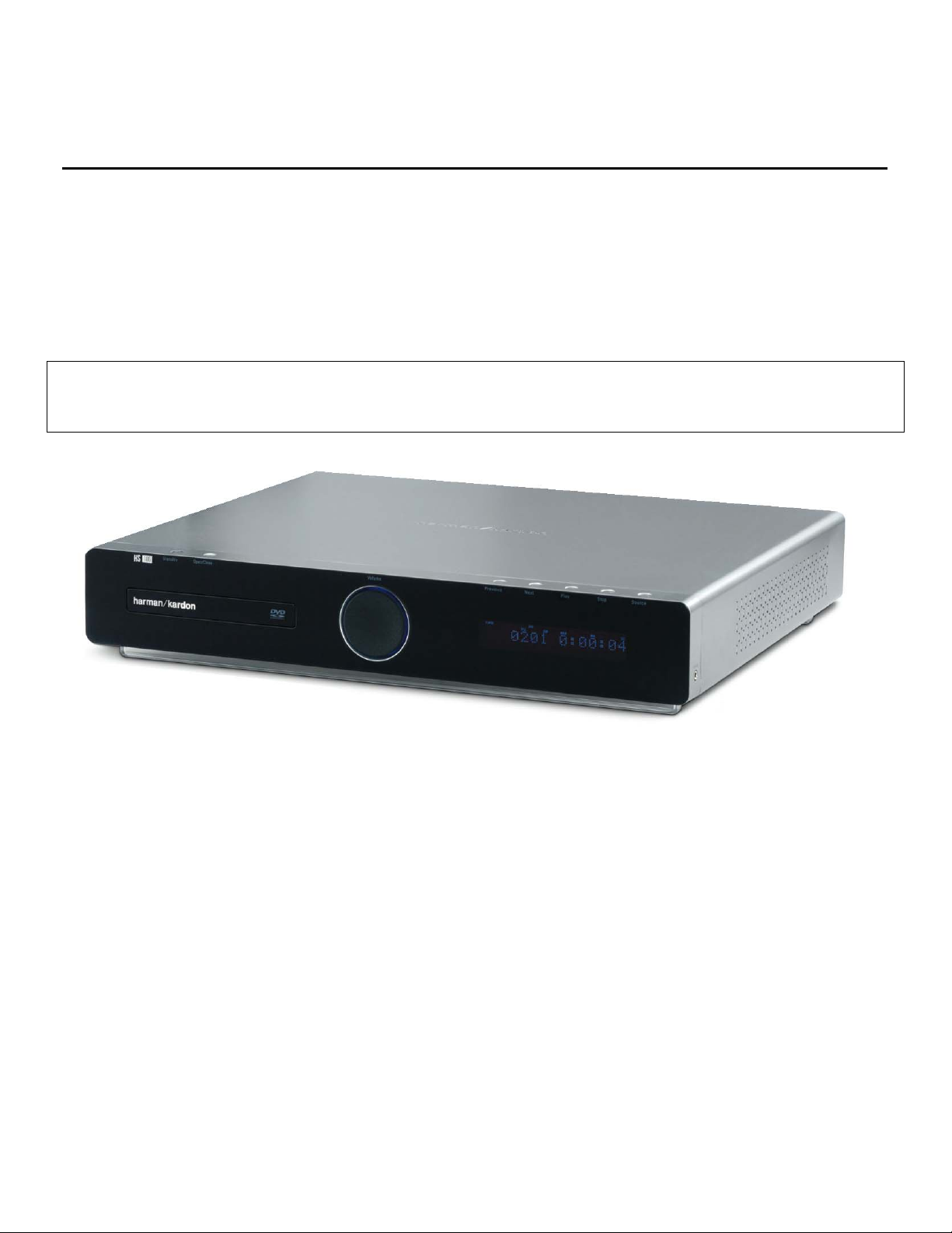
Model HS100
INTEGRATED HOME THEATER SYSTEM
DVD/ DVD-Audio/DVD±R/RW/CD/CD±R/VCD/SVCD Player
5 X 35W 5.1 CHANNEL A/V RECEIVER
Service Manual
- Contents -
SERVICING PRECAUTIONS……………...……2
ESD PRECAUTIONS……..…….…....................4
SPECIFICATIONS………………………….…….5
PACKAGING/ACCESSORIES………..…..…….6
FRONT PANEL CONTROLS……………..…….7
INFORMATION DISPLAY……………………….8
REAR PANEL CONNECTIONS…………...…...9
REMOTE CONTROL………………..………….10
INSTALLATION/CONNECTIONS…..………….12
SYSTEM SETUP.................................…….…14
harman/kardon, Inc.
250 Crossways Park Dr.
Woodbury, New York 11797
BASIC OPERATION………….…….…………..…19
BASIC TROUBLESHOOTING GUIDE/RESET.…..…..….20
OVERALL EXPLODED VIEW……………..…..…21
BLOCK DIAGRAM.……………..…………..…..…22
HS100 ELECT R I C AL PART S LI ST……..…....... .2 3
HS100 MECHANICAL PARTS LIST…………….31
PCB DRAWINGS……………………………….…33
SEMICONDUCTOR PINOUTS………..…………43
SCHEMATICS…………………………..…………53
Rev 1 6/2007
Page 2
2
HS100 Integrated Hom e Theater System harman/kardon
SERVICING PRECAUTIONS
NOTES REGARDING HANDLING OF THE PICK-UP
1. Notes for transport and storage
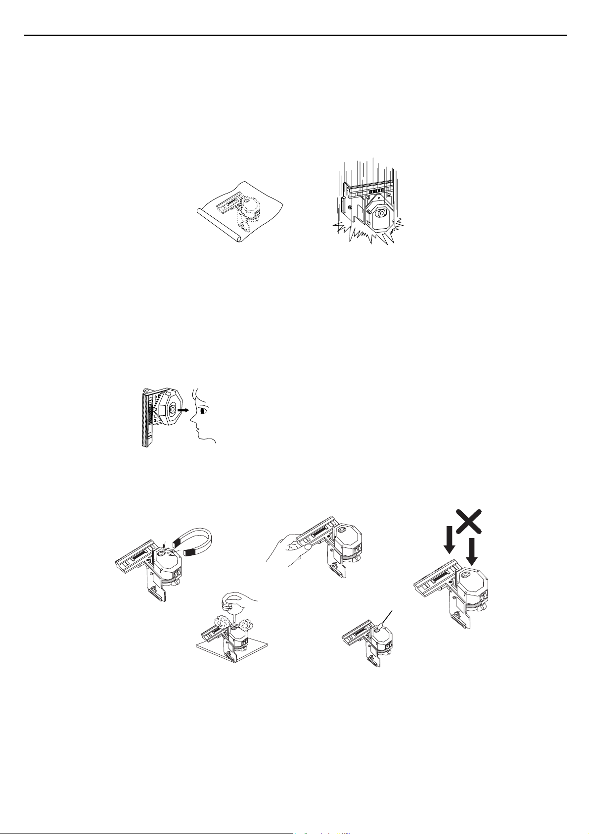
1) The pick-up should always be left in its conductive bag until immediately prior to use.
2) The pick-up should never be subjected to external pressure or impact.
Storage in conductive bag
Drop impact
2. Repair notes
1) The pick-up incorporates a strong magnet, and so should never be brought close to magnetic materials.
2) The pick-up should always be handled correctly and carefully, taking care to avoid external pressure and
impact. If it is subjected to strong pressure or impact, the result may be an operational malfunction
and/or damage to the printed-circuit board.
3) Each and every pick-up is already individually adjusted to a high degree of precision, and for that reason
the adjustment point and installation
screws should absolutely never be touched.
4) Laser beams may damage the eyes!
Absolutely never permit laser beams to enter the eyes!
Also NEVER switch ON the power to the laser output part (lens, etc.) of the pick-up if it is damaged.
NEVER look directly at the laser beam, and don’t let contact
fingers or other exposed skin.
5) Cleaning the lens surface
If there is dust on the lens surface, the dust should be cleaned away by using an air bush (such as used
for camera lens). The lens is held by a delicate spring. When cleaning the lens surface, therefore, a cotton swab should be used, taking care not to distort this.
Pressure
Magnet
Pressure
How to hold the pick-up
Cotton swab
Conductive Sheet
6) Never attempt to disassemble the pick-up.
Spring by excess pressure. If the lens is extremely dirty, apply isopropyl alcohol to the cotton swab. (Do
not use any other liquid cleaners, because they will damage the lens.) Take care not to use too much of
this alcohol on the swab, and do not allow the alcohol to get inside the pick-up.
Page 3
3
HS100 Integrated Hom e Theater System harman/kardon
NOTES REGARDING COMPACT DISC PLAYER REPAIRS
1. Preparations
1) Compact disc players incorporate a great many ICs as well as the pick-up (laser diode). These components are sensitive to, and easily affected by, static electricity. If such static electricity is high voltage,
components can be damaged, and for that reason components should be handled with care.
2) The pick-up is composed of many optical components and other high-precision components. Care must
be taken, therefore, to avoid repair or storage where the temperature of humidity is high, where strong
magnetism is present, or where there is excessive dust.
2. Notes for repair
1) Before replacing a component part, first disconnect the power supply lead wire from the unit
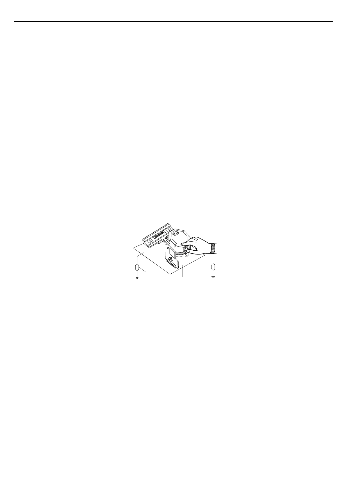
2) All equipment, measuring instruments and tools must be grounded.
3) The workbench should be covered with a conductive sheet and grounded.
When removing the laser pick-up from its conductive bag, do not place the pick-up on the bag. (This is
because there is the possibility of damage by static electricity.)
4) To prevent AC leakage, the metal part of the soldering iron should be grounded.
5) Workers should be grounded by an armband (1MΩ)
6) Care should be taken not to permit the laser pick-up to come in contact with clothing, in order to prevent
static electricity changes in the clothing to escape from the armband.
7) The laser beam from the pick-up should NEVER be directly facing the eyes or bare skin.
Resistor
(1 Mohm)
Armband
Resistor
(1 Mohm)
Conductive
Sheet
Page 4

4
HS100 Integrated Hom e Theater System harman/kardon
ESD PRECAUTIONS
Electrostatically Sensitive Devices (ESD)
Some semiconductor (solid state) devices can be damaged easily by static electricity. Such components commonly are called Electrostatically Sensitive Devices (ESD). Examples of typical ESD devices are integrated circuits and some field-effect transistors and semiconductor chip components. The following techniques should
be used to help reduce the incidence of component damage caused by static electricity.
1. Immediately before handling any semiconductor component or semiconductor-equipped assembly, drain off
any electrostatic charge on your body by touching a known earth ground. Alternatively, obtain and wear a
commercially available discharging wrist strap device, which should be removed for potential shock reasons
prior to applying power to the unit under test.
2. After removing an electrical assembly equipped with ESD devices, place the assembly on a conductive surface such as aluminum foil, to prevent electrostatic charge buildup or exposure of the assembly.
3. Use only a grounded-tip soldering iron to solder or unsolder ESD devices.
4. Use only an anti-static solder removal device. Some solder removal devices not classified as "anti-static"
can generate electrical charges sufficient to damage ESD devices.
5. Do not use freon-propelled chemicals. These can generate electrical charges sufficient to damage ESD
devices.
6. Do not remove a replacement ESD device from its protective package until immediately before you are
ready to install it. (Most replacement ESD devices are packaged with leads electrically shorted together by
conductive foam, aluminum foil or comparable conductive materials).
7. Immediately before removing the protective material from the leads of a replacement ESD device, touch the
protective material to the chassis or circuit assembly into which the device will by installed.
CAUTION : BE SURE NO POWER IS APPLIED TO THE CHASSIS OR CIRCUIT, AND OBSERVE ALL
OTHER SAFETY PRECAUTIONS.
8. Minimize bodily motions when handing unpackaged replacement ESD devices. (Otherwise harmless motion
such as the brushing together of your clothes fabric or the lifting of your foot from a carpeted floor can generate static electricity sufficient to damage an ESD device).
Page 5

SPECIFICATIONS 33
DVD Player
Pickup: Semiconductor laser, wavelength 650nm
Video signal system: NTSC
Video signal horizontal resolution: > 480 lines (DVD)
Video signal-to-noise ratio: > 60dB (DVD)
Audio frequency response: DVD (PCM): 20Hz – 22kHz (±1dB)
(Stereo) CD (PCM): 20Hz – 20kHz (±1dB)
Audio signal-to-noise ratio: >80dB (PCM)
Total harmonic distortion: < 0.01% (PCM)
Dynamic range: DVD (PCM): >85dB (EIAJ, 2kHz)
CD: >85dB (EIAJ)
FM Tuner
System: PLL quartz-locked digital synthesizer system
Tuning range: 87.50 – 108.00MHz
Antenna terminals: 75 Ohms, unbalanced
Intermediate frequency: 10.7MHz
AM Tuner Section
Frequency range: 520 – 1720kHz
Signal-to-noise ratio: 45dB
Usable sensitivity: Loop 500 µV
Distortion: 1kHz, 50% Mod 0.8%
Selectivity: ±10kHz, 30dB
Video Outputs
Component video output: Y: 1 Vp-p/75 ohms, sync negative polarity
Pr: 0.7 Vp-p/75 ohms
Pb: 0.7 Vp-p/75 ohms
Composite video output: 1 Vp-p/75 ohms
S-video output: Y: 1 Vp-p/75 ohms
C: NTSC 0.286 Vp-p/75 ohms
Audio Section
Amplifer power: 35 watts per channel, 20Hz – 20kHz,
< 0.5% THD into 6 ohms
Line output: 1 Vrms, 1 kilohm
General
Power requirements: AC 120V, 50Hz
Power consumption: 3W Standby, 380W Maximum
Dimensions (HxWxD): 2-11/16" x 17-15/16" x 2-3/16"
Weight: 10.6 lb
HS 100 SPECIFICATIONS
Depth measurement includes knobs, buttons and terminal connections. Height measurement includes feet and chassis.
All features and specifications are subject to change without notice.
Harman Kardon and Power for the Digital Revolution are registered trademarks of Harman International Industries, Incorporated.
Dolby, Pro Logic and the double-D symbol are trademarks of Dolby Laboratories, registered in the United States and/or other countries. All rights reserved.
DTS is a trademark of DTS, Inc.
* Windows Media
®
Audio (WMA) is a proprietary file format developed by Microsoft. Microsoft, Windows and Windows Media are registered trademarks of Microsoft Corporation in the United States
and/or other countries.
This product incorporates copyright protection technology that is protected by method claims of certain U.S. patents and other intellectual property rights owned by Macrovision
Corporation and other rights owners. Use of this copyright protection technology must be authorized by Macrovision Corporation and is intended for home and other limited
viewing uses only unless otherwise authorized by Macrovision Corporation. Reverse engineering or disassembly is prohibited.
Supplied Accessories
The following accessory items are supplied with the HS 100 controller. If any of these items are missing, please contact Harman Kardon customer service at
www.harmankardon.com.
• A system remote control • An AM loop antenna
• An FM wire antenna • Three AAA batteries
• AC power cord
HS 100 SPECIFICATIONS
5
HS100 Integrated Hom e Theater System harman/kardon
Page 6
16
6
HS100 Integrated Hom e Theater System harman/kardon
18
15
5
4
3
6
17
15
15
13
12
11
10
9
8
7
1
2
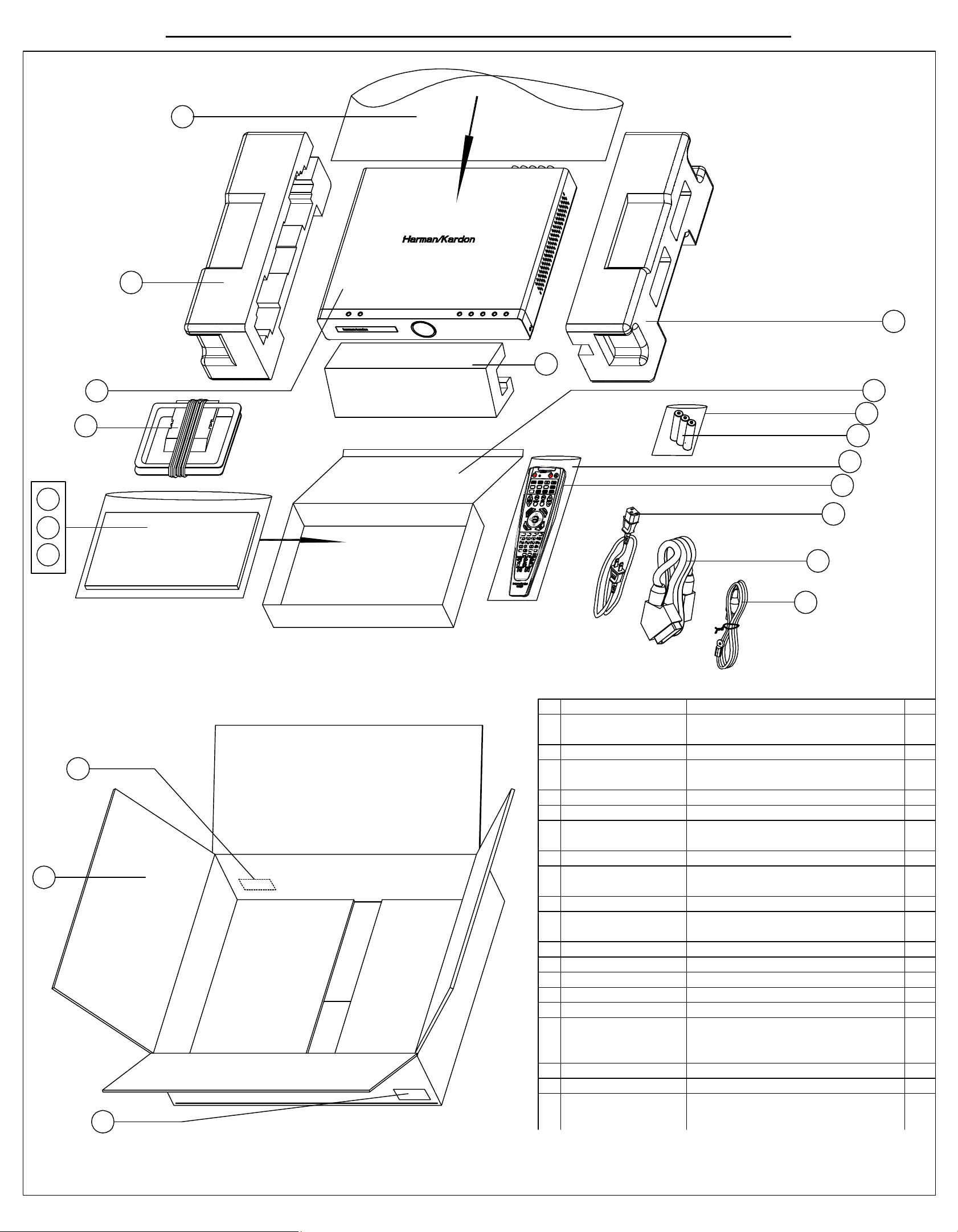
No. Part No. Description Qty.
1 01.00.BZ.X.W.E232 Carton box HS100 EU version 1
01.00.BZ.X.W.E231 Carton box HS100 US version 1
2 Barcord label 1
3 01.00.YS.SM1.E261 Owner manual HS100 US version 1
01.00.YS.SM1.E262 Owner manual HS100 EU version 1
4 Plastic bag for manual 25*35cm 1
5 01.00.YS.FY3.345 Safety instruction manual HS100 EU 1
01.00.YS.FY3.346 Warning card HS100 US version 1
01.00.YS.FY3.347 Guarantee card HS100 US version 1
6 01.47.CNT.CTX.042 AM antenna AM-300-AWM 1
7 01.47.CNT.CTX.037 FM antenna FM-075 1
01.47.CNT.CTX.038 FM antennab FM-TV-75-A 1
8 01.47.CNT.LJX.5.012 SCART cable 1
9 01.47.CNT.ACX.E052 AC power cord EU version 1
01.47.CNT.ACX.E053 AC power cord US version 1
1001.00.RC.100 Remote control HS100 1
11 Plastic bag for RC 9*27.5cm 1
1201.14.DX.B.0007 battery 7# battery 3
13 Plastic bag for battery 6*9c 1
14 accessories box 1
15 accessories Polyfoam 2
01.00.BZ.F.P.E100 Polyfoam HS100- left 1
01.00.BZ.F.P.E101 Polyfoam HS100- right 1
16 Main unit 1
17 Plastic bag for unit 54.5*60cm 1
2
Page 7
FRONT-PANEL CONTROLSFRONT-PANEL CONTROLS
FRONT-PANEL CONTROLS 55
NOTE: To make it easier to follow the instructions that refer to this illustration, a larger copy may be downloaded from the Product Support section for this product
at www.harmankardon.com.
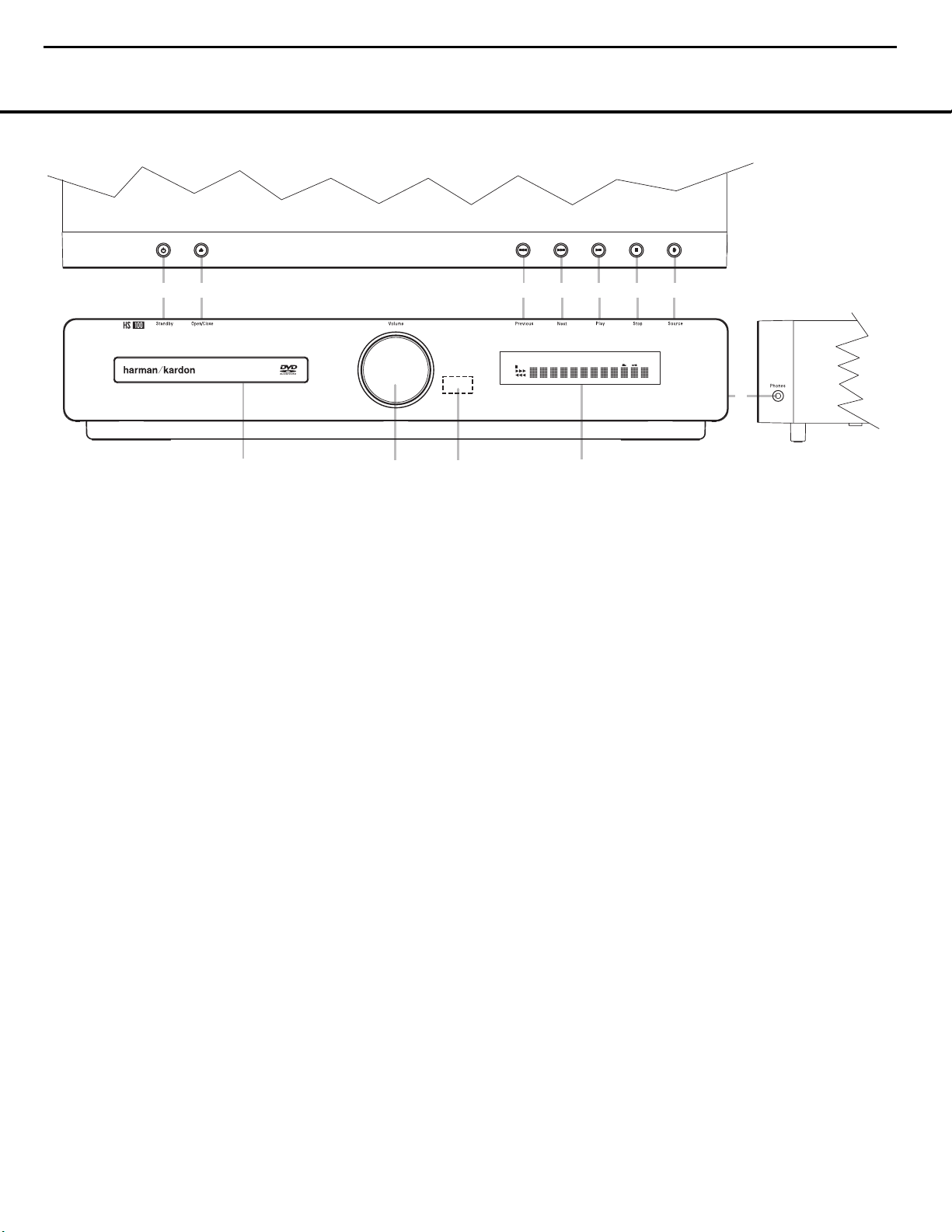
Power On/Off (Standby): When the HS 100
is connected to AC power, the ring around this button
will glow amber, indicating that the unit is in Standby
and is ready to be turned on. Press this button (or the
Power On Button 0 on the remote control) to turn
the unit on. When the unit is on, the amber illumination
around the button turns blue and the lighting surrounding the Volume Control A will turn blue.
1
Open/Close: Press this button to open or close
the Disc Tray.
2
Skip (Previous): Press this button to move
backward through the music tracks on a CD or the
chapters on a DVD.
3
Skip (Next): Press to move forward through the
music tracks on a CD or the chapters on a DVD.
4
Play/Pause: Press to initiate playback or to
momentarily pause playback. To resume playback,
press the button again. If a DVD is playing, action will
freeze and a still picture will be displayed when the
button is pressed.
5
Stop: Press this button once to place the disc in
the Resume mode, which means that playback will
stop; but as long as the tray is not opened, DVD playback will continue from the same point on the disc
when the Play button is pressed again. Resume will
also work if the unit was turned off. When this button
is pressed twice, playback of the disc will restart at
the beginning of the disc.
6
Source: Press this button repeatedly to scroll
through the available audio and video sources.
7
Headphone Jack: This jack may be used to listen
to the system’s output through a pair of headphones
with a standard 3.5mm stereo mini plug. Note that the
main room speakers will automatically be turned off
when the headphone jack is in use.
8
Information Display: This display delivers mes-
sages and status indications to help you operate the
HS 100 controller.
9 Remote Sensor: The infrared sensor that
receives commands from the remote control is behind
the front-panel lens in this area. To ensure proper
operation of the HS 100, it is important that this area
is not blocked or covered.
A
Volume Control: Turn this knob clockwise to
increase the volume, counterclockwise to decrease the
volume. If the HS 100 is muted, adjusting the volume
control will automatically release the unit from the
silenced condition.
B Disc Drawer: This drawer holds the discs played
in the HS 100. Be certain to properly seat all discs
carefully in the recess in the drawer tray. Do not
press down on the drawer when it is open, as this
will damage the player.
Power On/Off (Standby)
1
Open/Close
2
Skip (Previous)
3
Skip (Next)
4
Play/Pause
5
Stop
6
Source
7
Headphone Jack
8
Information Display
9
Remote Sensor
A
Volume Control
B
Disc Drawer
7
HS100 Integrated Hom e Theater System harman/kardon
1
2
3
PLAYER
DVD-AUDIO
5.1ch
CD
JPEG MP3
RADIO
VCD
AUX
DVD
DIGITAL IN
WMA
PROG
RAND
HOUR
TRACK
CHAP
TITLE
GROUP
4
REP
PBC
5
6
A-B
P.SCAN
TEST
1 ALL
SEC
MIN
V.OFF
7
B
A
9
8
Page 8
FRONT-PANEL DISPLAY
6 FRONT-PANEL DISPLAY
NOTE: To make it easier to follow the instructions that refer to this illustration, a larger copy may be downloaded from the Product Support section for this product
at www.harmankardon.com.
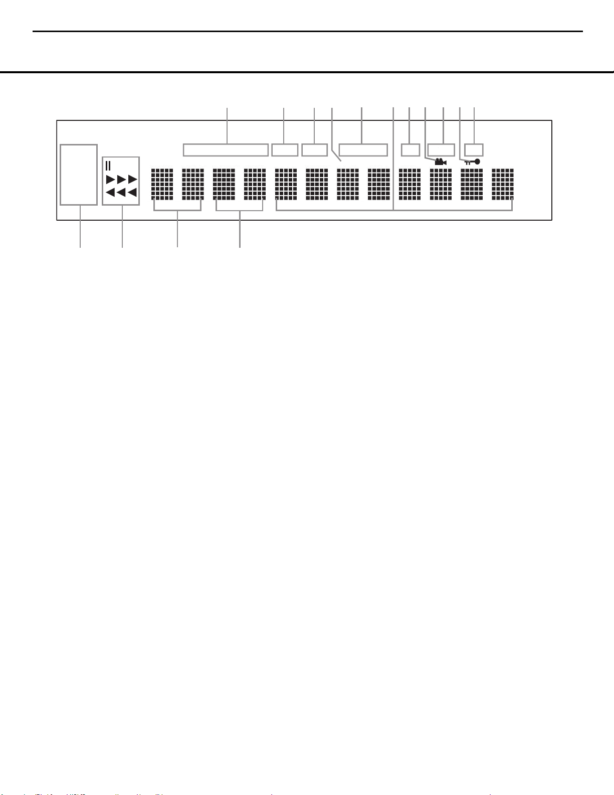
A Disc Type Indicators
B Program Indicator
C Random Indicator
D VCD Playback Control Indicator
E Repeat Indicators
F Time Indicators
G A-B Repeat Indicator
H Angle Indicator
I Progressive Scan Indicator
J Parental Lock Indicator
K Test Indicator
L Source Indicators
M Playback-Mode Indicators
N Title Indicators
O Chapter/Track Number Indicators
A
Disc Type Indicators: The CD, DVD or DVD-Audio
indicator will light to show the type of disc currently
being played.
B Program Indicator: This indicator lights when the
programming functions are in use.
C Random Indicator: This indicator lights when the
unit is in the Random Play mode.
D VCD Playback Control Indicator: This indicator
lights when the playback control function is turned on
with VCDs.
E Repeat Indicators: These indicators light when
any of the Repeat functions are in use.
NOTE: In addition to functioning individually to display
information about DVD, DVD-Audio or CD discs, the
NOF indicators also are used together as a group
to display information messages about the status of
the HS 100, such as the selected input’s name and
surround mode, the station playing when the tuner
is in use and specific function messages when a
DVD, DVD-Audio or CD disc is playing (such as
Reading when the disc is loading).
F Time Indicators: These positions in the indicator
will show the running time of a DVD in play. When a
CD is playing, these indicators will show the current
track time, time remaining in the current track, or the
total remaining time on the disc.
G A-B Repeat Indicator: This indicator lights when
a specific passage for repeat playback has been
selected.
H Angle Indicator: This indicator blinks when alter-
nate viewing angles are available on the DVD currently
playing.
I Progressive Scan Indicator: This indicator lights
when the unit sends out a progressive scan signal.
J Parental Lock Indicator: This indicator lights
when the parental lock system is engaged in order to
prevent anyone from changing the rating level without
a code.
K Test Indicator: This indicator lights when the TV
test screen is activated.
L Source Indicators: These indicators will light to
show which source is currently selected.
M Playback-Mode Indicators: These indicators light
to show the current playback mode:
N
Lights when a disc is playing in the normal mode.
NNN
When the HS 100 is in the Fast Search play
mode, two or three of these indicators will light to
show that the unit is in a Fast Play mode, depending
on the speed.
1
Lights when the disc is paused.
‹‹‹
Lights when the disc is in the Fast Search
Reverse mode. Two or three of these indicators will
light to show that the unit is in a Fast Play mode,
depending on the speed.
N Title Indicators: These two positions in the dis-
play will show the current title number when a DVD
disc is playing.
O Chapter/Track Number Indicators: When a
DVD disc is playing, these two positions in the display
will show the current chapter. When a CD is playing,
they will show the current track number.
8
HS100 Integrated Hom e Theater System harman/kardon
K
TEST
SEC
PLAYER
JPEG MP3
RADIO
VCD
AUX
DVD
DIGITAL IN
GROUP
CD
TITLE
A
DVD-AUDIO
TRACK
5.1ch
CHAP
B
PROG
C
RAND
HOUR
D
REP
PBC
E
1 ALL
HJ
GF
A-B
I
P.SCAN
MIN
WMA
L
M
N
O
Page 9
REAR-PANEL CONNECTIONS 7
REAR-PANEL CONNECTIONS
0
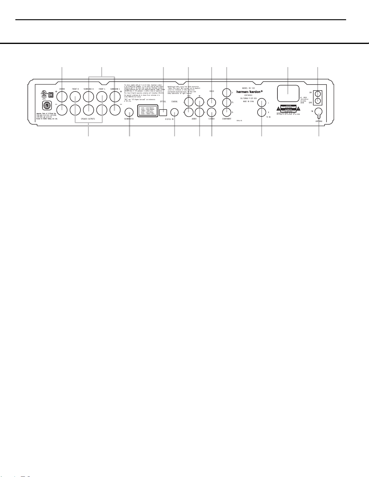
Center Speaker Outputs
1
Front Speaker Outputs
2
Surround Speaker Outputs
3
Subwoofer Output
4
Optical Digital Input
5
Coaxial Digital Input
6
Analog Audio Outputs
7
Analog Audio In
8
Composite Video Output
9
S-Video Output
A
Component Video Outputs
B
TV Audio In
C
AC Power Cord Jack
D
FM Antenna
E
AM Antenna
NOTE: To make it easier to follow the instructions that refer to this illustration, a larger copy may be downloaded from the Product Support section for this product
at www.harmankardon.com.
0
Center Speaker Outputs: Connect these outputs
to the matching + and – terminals on your center
channel speaker. The Green terminal is the positive (+)
terminal that should be connected to the Red (+) terminal on the speakers. Connect the Black (–) terminal
on the HS 100 to the Black negative (–) terminal on
your speaker. (See page 12 for more information on
speaker polarity.)
1
Front Speaker Outputs: Connect these outputs
to the matching + or – terminals on your left and right
speakers. The White terminal is the positive (+) terminal
that should be connected to the Red (+) terminal on
Front Left speaker, while the Red terminal is the positive
(+) terminal that should be connected to the Red (+)
terminal on Front Right speaker. Connect the Black (–)
terminals on the HS 100 to the Black (–) terminals on
the speakers. See page 11 for more information on
speaker polarity.
2
Surround Speaker Outputs: Connect these out-
puts to the matching + and – terminals on your surround channel speakers. The Blue terminal is the positive (+) terminal that should be connected to the Red
(+) terminal on the Surround Left speaker, while the
Gray terminal should be connected to the Red (+)
terminal on the Surround Right speaker. Connect the
Black (–) terminal on the HS 100 to the matching
Black negative (–) terminals for each surround speaker.
(See page 11 for more information on speaker
polarity.)
NOTE: You’ll find more details about all Audio/Video
connections under Setup and Connections on the
following pages.
3
Subwoofer Output: Connect to the SUB/LFE input
on the subwoofer.
4
Optical Digital Input: Connect the optical digital
output from an HDTV receiver, LD player, MD player,
satellite receiver or CD player to this jack. The signal
may be a Dolby Digital signal, DTS signal or a standard
PCM digital source.
5
Coaxial Digital Input: Connect the coax digital
output from an HDTV receiver, LD player, MD player,
satellite receiver or CD player to this jack. The signal
may be a Dolby Digital signal, DTS signal or a standard
PCM digital source. Do not connect the RF digital output of an LD player to these jacks.
6
Analog Audio Outputs: Connect these jacks to
the Record/Input jacks of an audio recorder for
recording.
7
Analog Audio In: Connect to the output of a
line-level analog audio source: TV, tape player,
Minidisc, PC, etc.
8
Composite Video Output: Connect this jack to the
video input on a television or video projector.
9
S-Video Output: Connect this jack to the S-video
input on a television or video projector.
A
Component Video Outputs: These outputs carry
the component video signals for connection to display
monitors with component video inputs. For standard
analog TVs or projectors with inputs marked Y/Pr/Pb or
Y/Cr/Cb, connect these outputs to the corresponding
inputs. If you have a high-definition television or projector that is compatible with high-scan-rate progressive
video, connect these jacks to the “HD Component”
inputs. Note that if you are using a progressive scan
display device, then “Progressive” must be selected in
the Video Setup menu in order to take advantage of the
progressive scan circuitry. See page 14 for more information on progressive scan video.
IMPORTANT: These jacks should NOT be connected to
standard composite video inputs.
B TV Audio In: Connect the analog left/right outputs
of a cable TV set-top, satellite receiver, or the analog
left/right stereo outputs from a video display with integrated digital tuner to these jacks.
C
AC Power Cord: Connect the AC power cord to
this jack when the installation is complete. To ensure
safe operation, use only the power cord supplied with
the unit. If a replacement is required, it must be of the
same type and capacity.
D
FM Antenna Jack: Connect to the supplied FM
antenna.
E AM Antenna: Connect the AM loop antenna sup-
plied with the receiver to these terminals with the white
wire connected to the “AM” terminal and the black wire
connected to the “GND” terminal. If an external AM
antenna is used, make connections to the AM and GND
terminals in accordance with the instructions supplied
with the antenna.
9
HS100 Integrated Hom e Theater System harman/kardon
0
1
2
3
4
6
5
7
8
9
A
C
B
E
D
Page 10
8 REMOTE CONTROL
REMOTE CONTROL
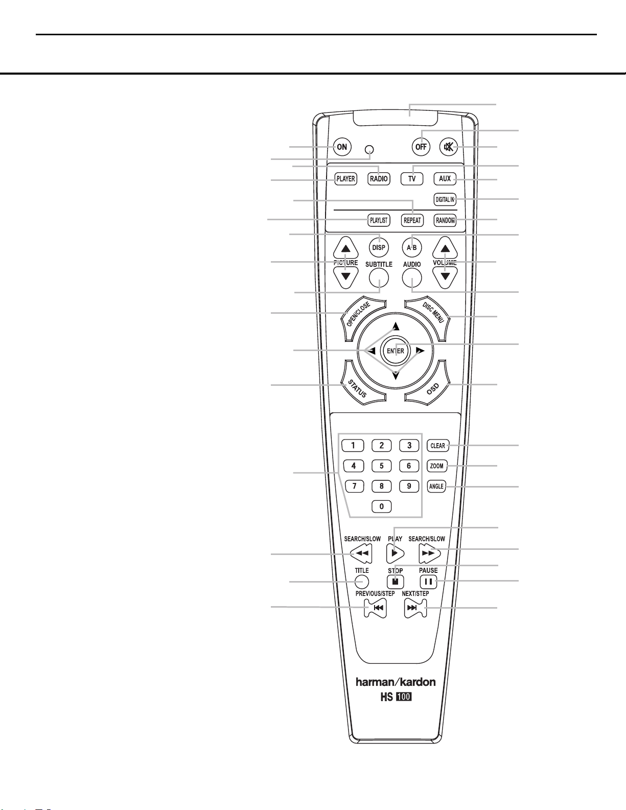
0
Power On
1
Transmit Indicator
2
Radio
3
Player
4
Repeat
5
Playlist
6
Display
7
Pic +/Pic –
8
Subtitle
9
Open/Close
A
Navigation Buttons
B
Status
C
Numeric Keys
D
Search/Slow Reverse
E
Title
F
Skip/Step (Previous)
G
Skip/Step (Next)
H
Pause
I
STOP
J
Search/Slow Forward
K
Play
L
Angle
M
Zoom
N
Clear
O
OSD
P
Enter
Q
Disc Menu
Audio
Volume Control
A-B Repeat
Random
Digital In
AUX
TV
Mute
Power Off
IR Transmitter Window
NOTE: To make it easier to follow the instructions
that refer to this illustration, a larger copy may be
downloaded from the Product Support section for
this product at www.harmankardon.com.
10
HS100 Integrated Hom e Theater System harman/kardon
1
3
5
7
9
B
D
F
0
2
4
6
8
A
C
E
Q
P
O
N
M
L
K
J
I
H
G
Page 11

REMOTE CONTROL 9
REMOTE CONTROL
0
Power On: Press this button to turn the HS 100
on when it is in Standby mode.
1 Transmit Indicator: This LED will light red when
any button is pressed to confirm that the remote code
is being transmitted.
2
Radio: Press this button to select the internal
tuner as the input source. When the tuner is in use,
press this button to switch between the AM and FM
frequency bands.
3
Player: Press this button to select the internal
CD/DVD drive as the input source.
4
Repeat: Press this button to go to the Repeat
menu. You can repeat a chapter, track or the
entire disc.
5
Playlist: Press this button to change the playback
order of the disc.
6
Display: Press this button to change the bright-
ness of the front-panel display or to turn the display off
completely in the following order: FULL BRIGHTNESS
➜ HALF BRIGHTNESS ➜ OFF ➜ FULL BRIGHTNESS.
7
Pic +/Pic –: Press these buttons to move to the
previous or next image when viewing JPEG images.
8
Subtitle: When a DVD is playing, press this but-
ton to select a subtitle language or to turn subtitles off.
9
Open/Close: Press this button to open or close
the disc tray.
A
Navigation Buttons (M/N/K/L): Press
these buttons to move the cursor in the OSD.
B
Status: Press this button while a disc is play-
ing to view the banner display. Use the Navigation
Buttons
A
to move through the different features in
the banner display. When a symbol is highlighted, press
the Enter Button P on the remote to select it.
C
Numeric Keys: Press this button to select
numbers.
D
Search/Slow (Rev.): Allows you to search in
reverse through a disc while it is in Play mode. Each
time you press this button, the search speed changes
as indicated by a number of arrows on the right top of
your screen. After pressing the Pause Button H
and then pressing this button, each press will change
the slow-play speed as indicated by the number of
arrows on the right top of the screen.
E
Title: When a disc is playing, press this button to
go back to the first section of the disc.
F
Skip/Step (Previous): Press this button to go
to the beginning of the current track. Press it again
quickly to go to the beginning of the previous track.
After pressing the Pause Button H, each press
of this button will move the image in reverse, frame
by frame.
G
Skip/Step (Next): Press this button to go to the
beginning of the next track. After pressing the Pause
Button H, each press of this button will move the
image forward, frame by frame.
H
Pause: Press this button to freeze a picture (with
DVD/VCD) or pause playback (CD). Press it again for
normal playback.
I
Stop: Press this button to stop a disc. When a
disc is playing, if you press STOP and the Play Button
K
, the disc will resume play; i.e., it will start from the
same point on the disc where the unit was stopped.
If you press STOP twice and the Play Button
K
,
the disc will start from the beginning.
J
Search/Slow (Fwd.): Press this button to search
forward through a disc while it is in Play mode. Each
time you press this button, the search speed changes,
as indicated by a number of arrows on the right top of
your screen. After pressing the Pause Button H
and then pressing this button, each press of this button
will change the slow-play speed, as indicated by the
number of arrows on the right top of the screen.
K
Play: Press this button to begin playback of a
disc. If the disc drawer is open, pressing this button will
also close the drawer automatically.
L
Angle: Press this button to access various cam-
era angles on a DVD (if the DVD contains multiple
camera angles) or to rotate JPEG images.
M
Zoom: When a DVD or VCD is playing, press this
button to zoom the picture. There are four steps to the
zoom function, each progressively larger. Press through
each of the zoom stages to return to a normal picture.
N
Clear: Press this button to remove the Banner
menu from the screen.
O
OSD: Press this button to access the On-Screen
Display menu.
P
Enter: Press this button to activate a setting or
option.
Q
Disc Menu: Press this button to display the
actual DVD Disc menu on the TV screen in Play mode.
When playing discs with JPEG images, pressing this
button will access the thumbnails.
Audio: Press this button to access various audio
languages on a DVD (if the DVD contains multiple
audio streams).
Volume (+ or –): Increase/decrease the master
volume level.
A-B: Press this button to select section A-B and to
play repeatedly.
Random: Press this button for Random playback
in random order.
Digital In: Press this button to selects the audio
device connected to either digital audio input as the
input source.
AUX: Press this button to select the device con-
nected to the Audio In Jacks 7 as the input
source.
TV: Press this button to select the device con-
nected to the TV In Audio Jacks
B
as the input
source.
Mute: Press this button to mute the sound.
Press the button again, or press either of the Volume
Control Buttons
, to return to normal audio
output.
Power Off: Press this button to place the
HS 100 in the Standby mode.
IR Transmitter Window: Point this window
toward the HS 100 when pressing buttons on the
remote to make certain that the infrared commands
are properly received.
11
HS100 Integrated Hom e Theater System harman/kardon
Page 12
10 INSTALLATION AND CONNECTIONS
INSTALLATION AND CONNECTIONS
Installation and Connections
After unpacking the HS 100 controller unit and the
speakers, the first step is to place each speaker and
the HS 100 controller unit in its location in your listening room. Consult the separate owner’s manual packed
with the speaker system for detailed information on
physical mounting of the speakers.
When making any connections between speakers and
the HS 100, as well as between the HS 100 and other
audio/video components, it is important that both the
HS 100 and external components be turned off,
preferably with the power removed from the AC outlet.
This protects against accidental turn-on that might
cause damage not covered by the products’ warranty.
When placing any speaker or the controller, make certain that it is on a solid surface capable of supporting
its weight, and make certain that there is a means for
connecting cables or speaker wires to reach through
the back of any cabinets or shelves to the components
they are connected to. As important, please note that
due to the weight of the speaker cabinets, particularly
the subwoofer, and the weight of and heat generated
by the HS 100 controller, there is the remote possibility
that the rubber padding on the bottom of the feet of
the system components may leave marks on certain
soft woods, wood veneers or carpets. Always use caution when placing any speaker or electronic component
on a material that is soft or porous, or of a significantly
different color than the feet or rubber padding on the
component.
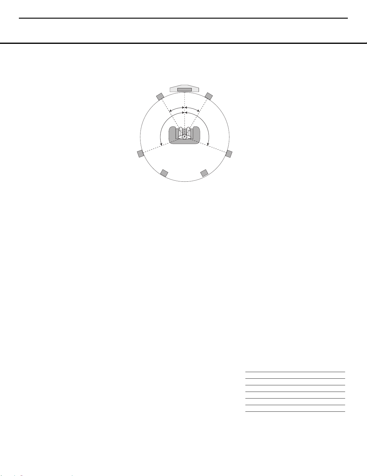
Speaker Placement
It is important that the speakers be placed in positions
that enable them to do the best job of reproducing the
sound as it was meant to be heard, regardless of the
program content. Particularly in a multichannel 5.1 system, the placement of speakers can have a noticeable
impact on the accuracy of the surround process.
When placing your speakers in a listening room, picture an imaginary circle starting at the center of your
video screen that arcs around the room with the prime
listening position, or “sweet spot” at the center of the
circle. Depending on the number of speakers in your
system, there is a recommended placement along the
arc for each speaker, though the specific construction
of your room (taking into account the available walls,
bookcases, or floor space at which the speakers may
be placed) will obviously have some impact on where
the speakers are ultimately located. As a general rule,
try to place all speakers so that they are positioned at
the same height as your ears when you are seated at
the prime listening position.
Use the following suggestions as a guide, and make
the changes needed to fit the speakers to your room.
Don’t be afraid to experiment a bit until you find the
right combination of locations that works for you. There
is no real “right” or “wrong” place to put the speakers;
work to optimize their locations so that audio moves
across the front of the room smoothly, without seeming
to jump from one speaker to another.
Center Channel Speaker
The ideal location for the center channel speaker is at
“0 degrees” in our circle, directly in front of the prime
listening position. Place the center channel speaker as
close to the top (or bottom) of the video screen as
possible so that when you position the front left/right
speakers the tweeters of all three front channel speakers are within 24" of one another.
Front Left/Right Speakers
The recommended placement for front left/right speakers is to place them at the 30-degree position with reference to the center channel speaker. The distance
between them should be about the same as the distance from the center channel speaker to the prime
listening position.
Although the natural tendency is to place the speakers
so they are parallel to the wall behind them, and thus in
line with the video screen, the preferred placement is
to angle the speakers slightly (“toe in”) so that they
point to the prime listening position.
Surround Speakers
In a 5.1 surround system, an additional pair of left/right
speakers is added to the front left, right and center
speakers. Although many believe that these speakers
should be placed at the rear of the room, the preferred
position for them is at the sides of the room, with rear
placement a second option when room conditions prevent the use of side-mounted surround speakers.
When side-wall mounting is possible, place the left/right
surround speakers at a point that is 110 degrees along
our circle from the center of the video screen. This
translates to placing them to the side and slightly
behind your preferred listening position. If possible,
angle the speakers in slightly so that they are pointing
toward the listener’s ears.
If it is not possible to place the surround speakers at
the sides of the room, the alternate position is at the
back of the room, about 150 degrees on our circle
from the center of the video screen. Another way to
spot the optimal, alternate rear-wall mounting position is
to place the left surround speaker on the back wall so
that it points directly at the front right speaker, and to
have the right surround speaker point directly at the
front left speaker. If possible aim the surround speakers
so that they point “in” toward the listening area, rather
than perpendicular to the walls.
NOTES ON SPEAKER PLACEMENT:
The limitations of your listening room, including the
placement of walls and furniture, may make it difficult
to follow the speaker placement suggestions shown
above. Depending on the specific layout of the room,
here are some ways to compensate for unusual
conditions:
• Try to follow the suggested placement, but move
the speakers within a few feet from the preferred
locations.
• Regardless of where they are placed, always try to
make certain that the main surround speakers are
the same distance from the front speakers. (For
example, try not to have the right surround speaker
further back into the room than the left surround
speaker.)
• If it is not possible to wall-mount or place speakers
on a shelf, consider the use of optional floor stands.
Main Speaker Connections
Once you have placed your left, center, right and surround speakers in the listening room, use the speaker
wire supplied with the HKTS 7 speaker system to connect the individual speakers to the rear panel of the
HS 100. Follow the instructions in the HKTS 7 owner’s
manual concerning connection of the speaker wire to
the back of each of the main speakers.
To simplify installation, the speaker wire included with
the HKTS 7 has a color marking tab at each end of the
wire to indicate the channel the wire’s speaker is connected to. When connecting the wire to the speakers,
we strongly recommend that you connect the wire in
con
formance with this color code, as it then makes it
easier
to match the color code for the speaker termi-
nals on the HS 100.
The color coding is as shown below:
Speaker Position Cable Color Code
Front Left White
Center Green
Front Right Red
Surround Right Gray
Surround Left Blue
If you wish to shorten the length of the speaker wires,
a set of colored stickers is included with the HKTS 7
owner’s manual. For consistency, apply the tab to the
12
HS100 Integrated Hom e Theater System harman/kardon
Video Screen
Center Speaker
30° 30°
Front Right
Speaker
110 °
Side Surround
Right Speaker
Side Surround
Left Speaker
Front Left
Speaker
110 °
Alternate position for surround positions
Page 13
INSTALLATION AND CONNECTIONS 11
INSTALLATION AND CONNECTIONS
side of the cable pair that has a white stripe. The
speaker wires are not only color-coded for channel
identification; they are also color-coded for polarity.
Since proper polarity is important for system performance, note that the side of each cable pair with the
white stripe and color tab is the positive side, and the
pure black side of the cable pair is the negative. When
connecting the cables to the speakers, the red speaker
terminal is positive (+), and should be connected to the
side of the wire with the white stripe and color tab. The
pure black side of the cable, where there is no color
tab, is negative and should be connected to the black
speaker terminal.
Once the wires are connected at the speaker end, connect each speaker to the rear panel of the HS 100.
The color-coding on the speaker wire connectors
makes it easy to make the connections properly.
The positive (+) connection for the Front Speaker
Connections 1 are white for left and red for
white, positive connection for the Center Speaker
Connection 0 is green, and the positive connections
for the Surround Speakers 2 are blue for left and
gray for left. In each case, the corresponding black side
of each speaker cable is the negative (–) connection
and goes to the matching black terminal for the
speaker.
Subwoofer Placement and Connection
Since subwoofers produce nondirectional sound, they
may be placed almost anywhere in a room. Actual
placement should be based on room size and shape
and the type of subwoofer used. One method of finding the optimal location for a subwoofer is to begin by
placing it in the front of the room, about six inches
from a wall, or near the front corner of the room.
Another method is to temporarily place the subwoofer
at your normal listening position, and then walk around
the room until you find a spot where the subwoofer
sounds best. Place the subwoofer in that spot, or you
may wish to experiment with the best location for a
subwoofer in your listening room.
Using the audio interconnect packaged with the
HKTS 7 system, connect one end to the Subwoofer
Output 3 on the rear panel of the HS 100 and
connect the other end to the “SUB” input on the
subwoofer.
Audio Equipment Connections
Since the HS 100 is a complete integrated home theater system with an onboard DVD Audio/Video player
and tuner, you may not need to make any additional
audio equipment connections. However, if you have any
external audio components, they should be connected
as follows:
Products with digital audio outputs, such as an external
CD changer, set-top cable box, satellite receiver, video
game console, compatible computer sound card or
HDTV receiver may be connected to either the
Optical 4 or Coaxial 5 Digital inputs.
Connections to the analog audio output of a cable settop, satellite receiver, or the Left/Right analog output of
a TV set with built-in digital television tuner should be
connected to the TV Audio Inputs B.
You may connect the outputs of any other analog audio
device, such as a phono preamp, video game console,
camcorder, audio recorder or similar to the Analog
Audio Inputs 7. If you are connecting an audio
recorder to the HS 100, the record/in jacks on the
recording device should be connected to the Analog
Audio Outputs 6 on the HS 100.
Video Equipment Connections
Depending on the type of TV set or video display to be
used, connect the HS 100 to the display using one of
the following methods:
• If you have a high-definition, or “digital”, television,
connect the Component Video Outputs B to a
matching set of component inputs on the display.
• If your TV set has only S-video and standard,
composite video inputs, we recommend that the
S-Video Output 9 be used as the connection.
• When a standard, composite video input is all that is
available on the TV set for video input, connect the
Composite Video Output 8 to the TV.
System Connections
Connect the FM antenna supplied with the HS 100,
or an optional, external FM antenna feed to the FM
Antenna Jack D. If the antenna uses 300-ohm
twin-lead cable, you must use an optional 300-ohm to
75-ohm adaptor to make the connection. Assemble
the supplied AM loop antenna so that the tabs at the
bottom of the antenna loop snap into the holes in the
base. Connect the white wire to the “AM” terminal and
the black wire to the GND Terminals E.
Connect the AC power cord to the AC Power Cord
Jack C, and then plug the cord into an unswitched
AC outlet. Note that the ring surrounding the Power
On/Off switch will turn amber to indicate that the
HS 100 is connected to an AC power source and
in the Standby mode.
System Preparation
Remove the protective plastic film from the HS 100’s
front-panel lens. If left in place, this film may affect the
performance of the remote control.
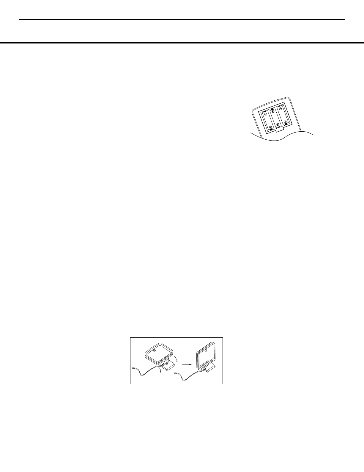
Install the three supplied AAA batteries in the remote,
as shown below.
To remove the battery cover, place your thumb on the
round inset area on the door and gently press upward
until the door slides out. When inserting the batteries
be certain to follow the (+) and (–) polarity indications
that appear at the bottom of the battery compartment.
Replace the battery compartment cover by pressing it
down toward the bottom of the remote until it snaps
into place.
Connecting the AC Power
You are now ready to power up the HS 100 controller
before beginning the final adjustments.
1. Plug the AC power cord into the AC Power Cord
Jack
C
, and then into an unswitched AC outlet.
Note that the Power Indicator
1
will turn orange,
indicating that the unit is in the Standby mode.
2. Turn the HS 100 on either by pressing the Power
On/Off
1
or the Input Source Selector4on
the front panel, or via the remote by pressing the
Power On Button
0
on the remote. The Power
Indicator
1
will turn blue to confirm that the unit is
on, and the Main Information Display
will also
light up.
Congratulations! You have now completed the physical
installation and connection of your HS 100 system and
only a few configuration steps are needed to tailor the
way the HS 100 operates to meet your needs and the
requirements of your listening room. Please continue
with the steps on the following pages to make certain
that your new system delivers all the performance it
was designed to provide.
13
HS100 Integrated Hom e Theater System harman/kardon
Page 14
12 SYSTEM SETUP
SYSTEM SETUP
System Setup
The final step in the installation of the HS 100 is to
establish the system’s configuration. Before proceeding,
make certain that the HS 100 is properly connected to
a video display and an AC power source. Turn on the
video display, and switch its input, if necessary, to the
input connected to the HS 100’s video output.
Turn on the HS 100 by pressing the Power On/Off
Switch on the front panel or the Power On
Button 0 on the remote. Note that the lighting
surrounding the Power On/Off Switch will turn
blue, a blue light will surround the front-panel Volume
Control 9, the Information Display 8 will light
and the HS 100 screen will appear on your video
display.
In many cases you will not need to change the default
settings. This is normal, as we have anticipated the typical system setup. Of course, you may return to the
setup menus and change them at any time to reflect a
change in your personal preferences or equipment
selection.
System Defaults
General Functionality of the OSD Menu
The setup and control of the HS 100 takes place in an
advanced user-guided On Screen Display (OSD) menu
system. The OSD can be activated by pressing the OSD
Button
O
on the remote control. Pressing this button
again de-activates the OSD.
The main menu consists of a PLAYER menu,
RADIO menu, TV menu, AUX menu,
DIGITAL IN menu and a SET-UP menu.
The PLAYER menu will show all information and
options available for the disc currently playing. The
RADIO menu will show radio and RDS options. The
TV, AUX and DIGITAL IN menus show the
surround options for these specific audio inputs.The
SET-UP menu will help you configure all audio and
video settings which are normally made only once.
Each main menu contains submenus.These submenus
are shown as icons on the left side of the menu. They
may be selected by moving the white highlighted square
around the icon by pressing the Navigation Buttons
A
. Menus may be activated by pressing the Enter
Button
P
when an icon is highlighted. When the
Enter Button
P
has been pressed, the color of the
icon will change to dark blue and the current settings of
this submenu will appear on the right side of the menu.
Although each menu has various submenus and
settings, they are all navigated in the same way. All submenus, settings and options can be accessed with the
help of the Navigation Button
A
and the Enter
Button
P
on the remote control.
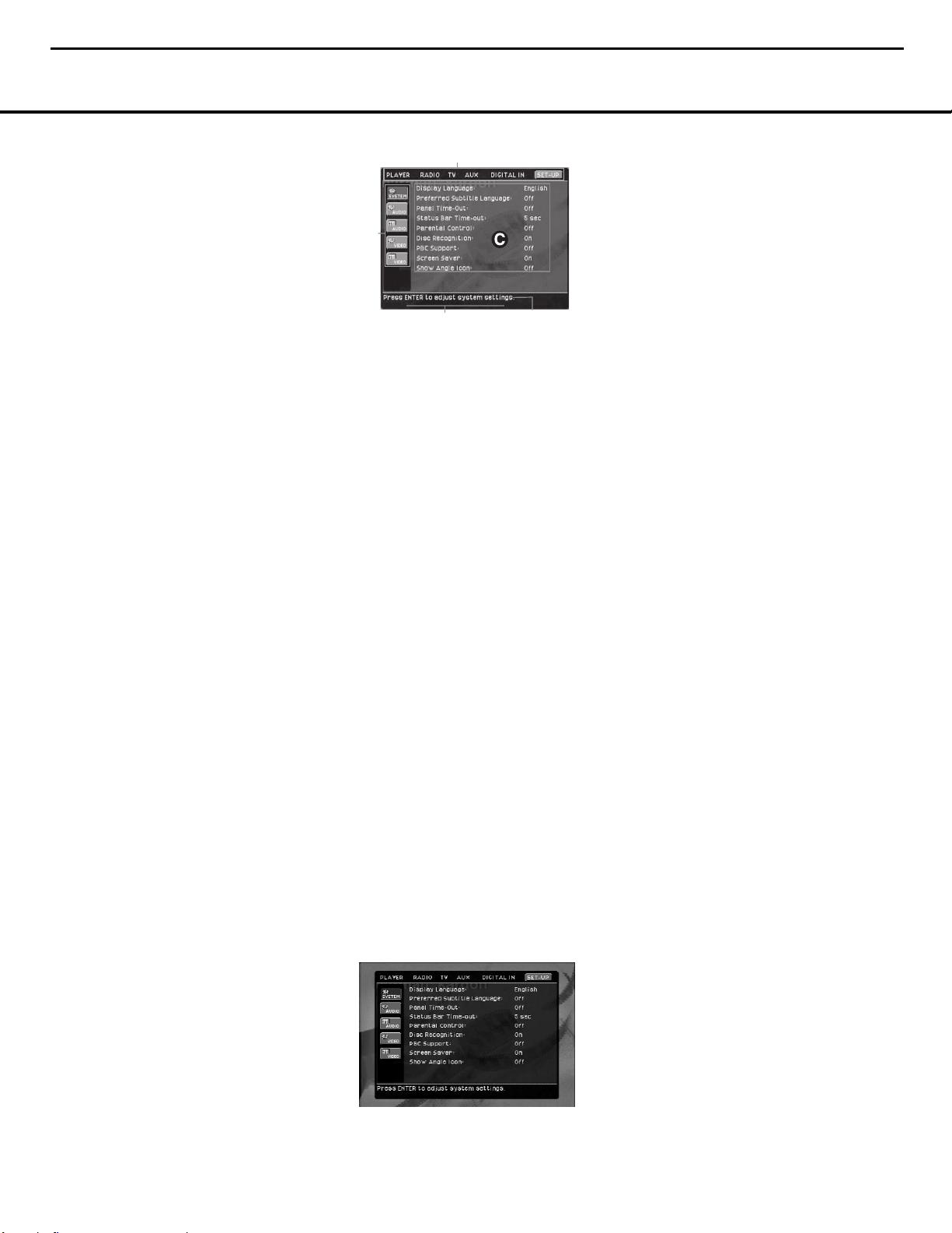
å Main Menu Line
∫ Submenus
ç Current Settings
∂ Command Descriptions
é Option Descriptions
To change a setting, simply move the highlight cursor to
the setting you wish to change.This setting will be highlighted in light blue, and a brief explanation will appear
in the Upper Menu Line on the bottom of your screen,
together with the available options for this setting on the
Lower Menu Line. Use the
M/N
Navigation Buttons
A
to highlight the requested option for this setting.
Press the Enter Button
P
to activate the new
setting.
Setup Menu
The first step in checking or changing the system
defaults is to access the SET-UP Menu. First,
make certain that the HS 100 Controller is properly
connected to a video display, and that power is
connected. For this process, however, you do not
need to load a disc into the unit.
During Stop, Pause or Play mode, if you press the OSD
Button
O
on the remote, the main menu appears on
the screen.
In the SET-UP menu you will find submenus for
making or changing all settings and adjustments for
both the Audio and Video aspects of your HS 100.
To access the SET-UP Menu, press the OSD Button
O
, and press theM/N/K/LNavigation
Buttons
A
until SET-UP is highlighted. Press
Enter Button
P
to activate the SYSTEM
settings:
System Settings
The System Setting submenu contains the following
sections. Follow the explanations in the Upper Menu
Line at the bottom of the screen to change settings.
Display Language: This setting selects the language
that will be used for the HS 100’s OSD menus and
other system messages. The default is English, but you
may also select French, Spanish, German or Italian.
Preferred Subtitle Language: This setting selects the
language used for the display of subtitles. The default
setting is OFF, which plays discs without subtitles. To
set the player so that subtitles will always play in a specific language when they are available, select from any
of the choices shown on the Option Descriptions É
when adjusting this item, as shown above. If you do not
find your preferred language in the list of options, you
may select a preferred language by first pressing the
‹/›
Navigation Buttons k during the setting
adjustment so that OTHER is highlighted. Press the
Enter Button z and then use the Numeric Keys
m to enter the four-digit code listed on page 31 for
the desired language. This selects a preferred subtitle
language, but it will only be available when the disc
being played contains that language. The list of subtitles available on any given disc is always shown on the
disc jacket, usually at the bottom of the back cover.
Note that the subtitles may also be switched on or off,
or a new language selected during playback using the
Subtitle Button 8, as described on page 21.
Panel Time-Out: This settings selects the time-out
interval for the front-panel Information Display 9.
The default setting is OFF, which disables this feature
so that the front-panel indicators are always illuminated.
You may also choose five to 20 seconds as the length
of time after you press any button on the front panel or
remote for the display to go out. To view the displays
when they are off, press any button on the remote.
Status Bar Time-Out: This setting selects the time-out
interval for the on-screen Status Bar that appears at the
top of your video screen when the Status Button l
is pressed while a disc is playing. During DVD playback,
the status bar shows the current title and chapter, as
well as the elapsed or remaining time in the current
title. You may program the status bar to remain on
screen for either five or 20 seconds after the Status
Button l is pressed. When OFF is selected, the
time-out is disabled, and the status bar will remain on
the screen until the Status Button l or Clear
Button x is pressed.
Parental Control: This setting enables you to restrict
viewing to films or other discs encoded with parental
control information to a specific level or below, and it
also allows you to change the password that must be
entered to change the settings for this option. The
default setting allows all discs to be played, but you
may change the setting so that viewing is controlled
within eight steps, with lower numbers being more
14
HS100 Integrated Hom e Theater System harman/kardon
å
∫
é
∂
Page 15
SYSTEM SETUP 13
SYSTEM SETUP
restrictive and high numbers allowing more material
to be viewed. The steps correspond to the standard
MPAA ratings symbols as follows. Additional information about movie ratings is available online at
www.mpaa.org/movieratings.
• Step 1 is equivalent to a “G” rating for general audiences with material appropriate for all viewers.
• Step 2 is an intermediate level between “G” and
“PG” rated material.
• Step 3 is equivalent to a “PG” rating.
• Step 4 is equivalent to a “PG-13” rating.
• Step 5 is an intermediate level between “PG-13” and
“R” rated material.
• Step 6 is equivalent to an “R” rating.
• Step 7 is equivalent to an “NC17” rating.
• Step 8 allows all discs to be played, regardless
of their content rating.
To access the Parental Control settings, press the
K/L
Navigation Buttons k until the current
setting on the Parental Control Settings line is highlighted and press the Enter Button z. Next, enter
the default password by pressing “8888” using the
Numeric Buttons m. Finally, use the
M/N
Navigation Buttons k to highlight the desired
parental control level as shown on the Options
Descriptioins É line as described above. You may
also change the password by highlighting NEW
PASSWORD, pressing Enter Button z and
by following the instructions that appear in the
Command Descriptions ∂ line.
Disc Recognition: This setting controls the Disc
Recognition feature. When turned on, it allows you to
pause a DVD-Video disc, remove it from the player,
play another disc, and then resume the playback of the
original disc at a later time from the point at which you
paused. When a previously played disc is reinserted
in the HS 100, an on-screen status message will ask
whether you wish to start playback from the beginning
of the disc or resume at the point where you left off.
Note that even when the setting is activated, you must
pause
the playback, rather than bring it to a full stop,
and the unit must not be turned off between discs.
PBC Support: This setting controls the activation of
PBC (Play Back Control) Support for VCD discs. If you
plan to play VCD discs, which are a CD-ROM-based
format that predates DVD, we recommend that the setting be turned ON.
Screen Saver: This setting controls the activation of
a screen saver that prevents the image of the “splash
screen” from being “burned” into the face of your video
display when a disc is stopped for more than five minutes. If you use the HS 100 with a plasma display,
direct-view CRT set or a CRT-based projector, we
strongly recommend that the setting be turned ON.
Show Angle Icon: This setting controls the activation
of the Angle Icon. When this setting is turned ON,
the Angle Icon, which is a small image of a movie
camera, will appear in the upper right corner of the
screen when multiple-angle material is available on the
disc being played. When the icon appears, press the
Angle Button v on the remote to switch between
the available views or program material.
Audio Setup Menu
This menu establishes the HS 100’s configuration for
general audio settings, such as preferred language and
digital audio settings.
As with all setup menus, press the OSD Button `
to activate the main menu screen, and then press the
M/N
Navigation Buttons k so that SETUP is
highlighted. Press Enter Button z, and then use
the
M/N/K/L
Navigation Buttons k until the
AUDIO SETUP menu is highlighted within a
white outline and press the Enter Button z again.
Finally, press the
M/N/K/L
Navigation Buttons
e once more to move the highlight to the Control
Settings ç side of the menu screen.
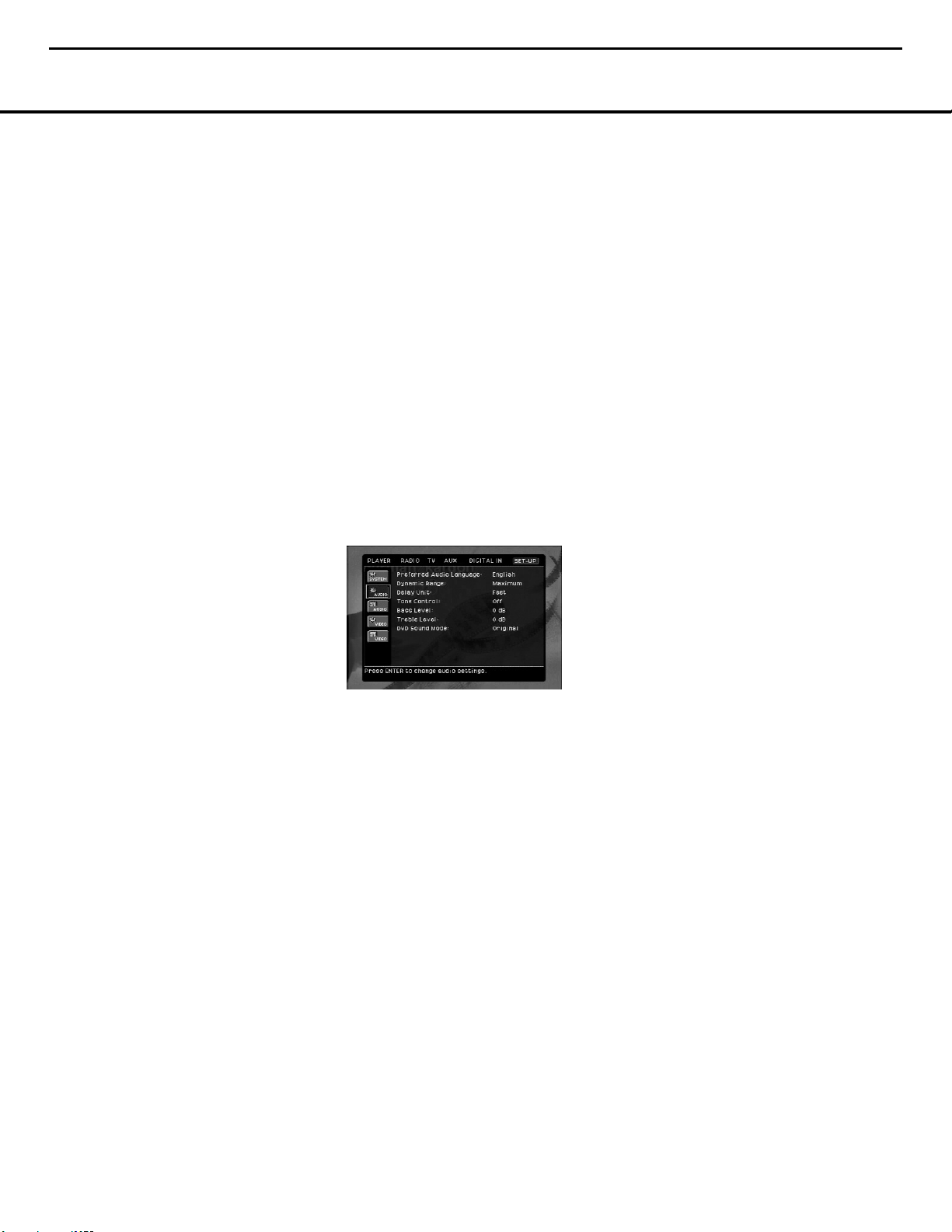
The following adjustments are available on the
AUDIO SETUP menu:
Preferred Audio Language: This setting is used to
select the default language that will be used for program playback. The factory default setting is English,
but you may choose French, Spanish, German or
Italian by making a selection on the Options
Descriptions É line. To select a language other than
those shown, select OTHER from the choices on
the Options Descriptions É line and press the
Enter Button z. Then, use the Numeric Keys p
to enter the four-digit code listed on page 31 for the
desired language. This selects a preferred audio program language, but it will only be available when the
disc being played contains that language. The list of
languages available on any given disc is always shown
on the disc jacket, usually at the bottom of the back
cover. Note that the audio playback language may
also be changed at any time during playback using
the Audio Button , as described on page 20,
but any changes made will only be effective during
playback of that disc.
Dynamic Range: This setting allows you to take
advantage of the programming present on some
Dolby Digital recordings to reduce the volume of
louder, peak passages while maintaining intelligibility
of quieter passages. This means that you may listen
to programs at a level that allows the full impact of a
soundtrack to be heard at a volume that is lower than
you might otherwise use to avoid complaints about
loud volume levels. The HS 100 accomplishes this by
compressing the audio to a greater or lesser degree,
depending on which setting you choose. Three options
are available:
• MINIMUM does not make any changes to the
original playback, and should be used when the
volume setting in the listening room may be as loud
as you desire.
• MEDIUM applies a moderate amount of com-
pression so that louder passages are a little quieter.
• MAXIMUM applies more compression so that
louder passages are much softer.
Feel free to experiment with the settings at any time.
Note that if your receiver or processor also allows you
to program the dynamic range setting, also known as
the “Night Mode,” you do not need to make any adjustments on the HS 100 and should leave the setting at
MINIMUM.
Delay Unit: This setting selects the measurement system used in entering delay times when the AUDIO
ADJUSTMENTS menu is activated. Distance
entry in feet is the default, but you may alternatively
choose to enter the distances in meters.
Tone Control: This setting determines whether the
Tone Controls are activated. When OFF is selected,
the audio output is run “flat” with no tone cut or boost.
When ON is selected, the tone control settings made
in the next two adjustments are applied.
Bass Level: When the Tone Control setting (above) is
ON, the amount of bass (low frequency) boost or cut
selected here is applied to the output signal. To change
the setting, make certain that the number at the right
side of the Bass Level Command Descriptions Line is
press the Enter Button P and then use the
Navigation Buttons A to change the setting.
Treble Level: When the Tone Control setting (above)
is ON, the amount of treble (high frequency) boost
or cut selected here is applied to the output signal. To
change the setting, make certain that the number at the
right side of the Treble Level Command Descriptions
Line is press the Enter Button P and then use the
M/N
Navigation Buttons A to change the setting.
DVD Sound Mode: This setting selects the surround
mode that will be used when a DVD is playing. (To set
the surround mode option for another input, such as “TV,”
“Digital In,” “AUX” or the unit’s internal AM/FM tuner, go
to the specific menu for that input.) The factory default
is ORIGINAL, which will play back DVDs in the
format output from the disc, such as Dolby Digital or
15
HS100 Integrated Hom e Theater System harman/kardon
Page 16
SYSTEM SETUP
14 SYSTEM SETUP
DTS. To select the mode that will be used when a disc
with two-channel audio is playing, make certain that
the mode name at the right side of the DVD Sound
Mode Command Descriptions Line is highlighted and
then press the Enter Button P. Use the
M/N
Navigation Buttons A to change the setting.
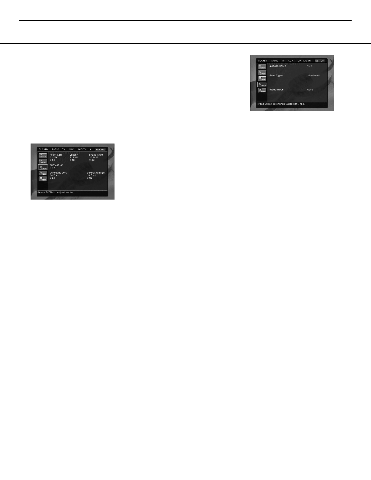
Audio Adjustment
The Audio Adjustment Submenu contains the speaker
delay and output level adjustment settings of the
HS 100. Follow the explanations in the Command
Options ∂ on the bottom of your screen to make
adjustments.
Delay
Due to the different distances between the listening
position for the front and surround channel speakers,
the amount of time it takes for sound to reach your
ears from each set of speakers is different. You may
compensate for this difference through the use of the
delay settings to adjust the timing for specific speaker
placement in your particular home theater or listening
room. Before proceeding, measure the distance
between each speaker and the preferred listening
location.
Next, press the
M/N/K/L
Navigation Buttons
A so that the second of the two AUDIO icons in
the Sub-Menus column ∫ is surrounded by a white
outline, with the icon box turning dark, rather than light,
blue. This is the Audio Settings Menu. Next, press the
M/N/K/L
Navigation Buttons A until the dis-
tance setting under the Front Left speaker title is highlighted and press the Enter Button P. To change
the setting, press the
M/N
Navigation Buttons A
so that the number highlighted in the Options
Description line é at the bottom of the screen is
the distance from the speaker to the listening position.
Press the Enter Button P when you are done.
Press the
M/N/K/L
Navigation Buttons A to
move across the menu screen to each of the distance
settings under each of the rest of the speaker positions, and repeat the procedure to enter the distance
setting. Note that distance setting for the subwoofer
does not need to be entered, as delay is not a factor
with low-frequency information.
Output Level Adjustment
Output level adjustment is a key part of the configuration process for any surround sound system.
NOTE:
Listeners are often confused about the operation
of the surround channels.While some assume that
sound should always be coming from each speaker,
most of the time there will be little or no sound in the
surround channels.This is because they are only used
when a movie director or sound mixer specifically
places sound there to create ambience, a special
effect or to continue action from the front of the room
to the rear. When the output levels are properly set,
it is normal for surround speakers to operate only
occasionally.Artificially increasing the volume to the
rear speakers may destroy the illusion of an enveloping
sound field, which duplicates the way you hear sound in
a movie theater or concert hall.
For ideal surround playback, the output level from each
channel should be equal, and in most cases the factory
default setting of 0dB should accomplish that. However,
in some cases the specifics of your listening room may
require some adjustments. To adjust the output levels,
first put in a disc with test tones or content you are
familiar with, and that has a reasonably even level without a great deal of changes. Then, press the
M/N
/
K/L
Navigation Buttons A until the output level
setting with the factory default of “+0dB” at the bottom
of the list under the Front Left speaker distance setting
is highlighted. If an increase or decrease needs to be
made to the level, press the Enter Button P and
then use the
M/N
Navigation Buttons A so
that the desired level is highlighted in the Options
Description line é at the bottom of the menu
screen. Press the Enter Button P, and then press
the
M/N/K/L
Navigation Buttons A to move
across the menu screen to each of the output level
settings under each of the rest of the speaker positions,
and repeat the procedure to enter the output level offset, if needed, that brings all of the channels to the
same output volume. You may need to repeat this procedure more than once to accurately set the levels.
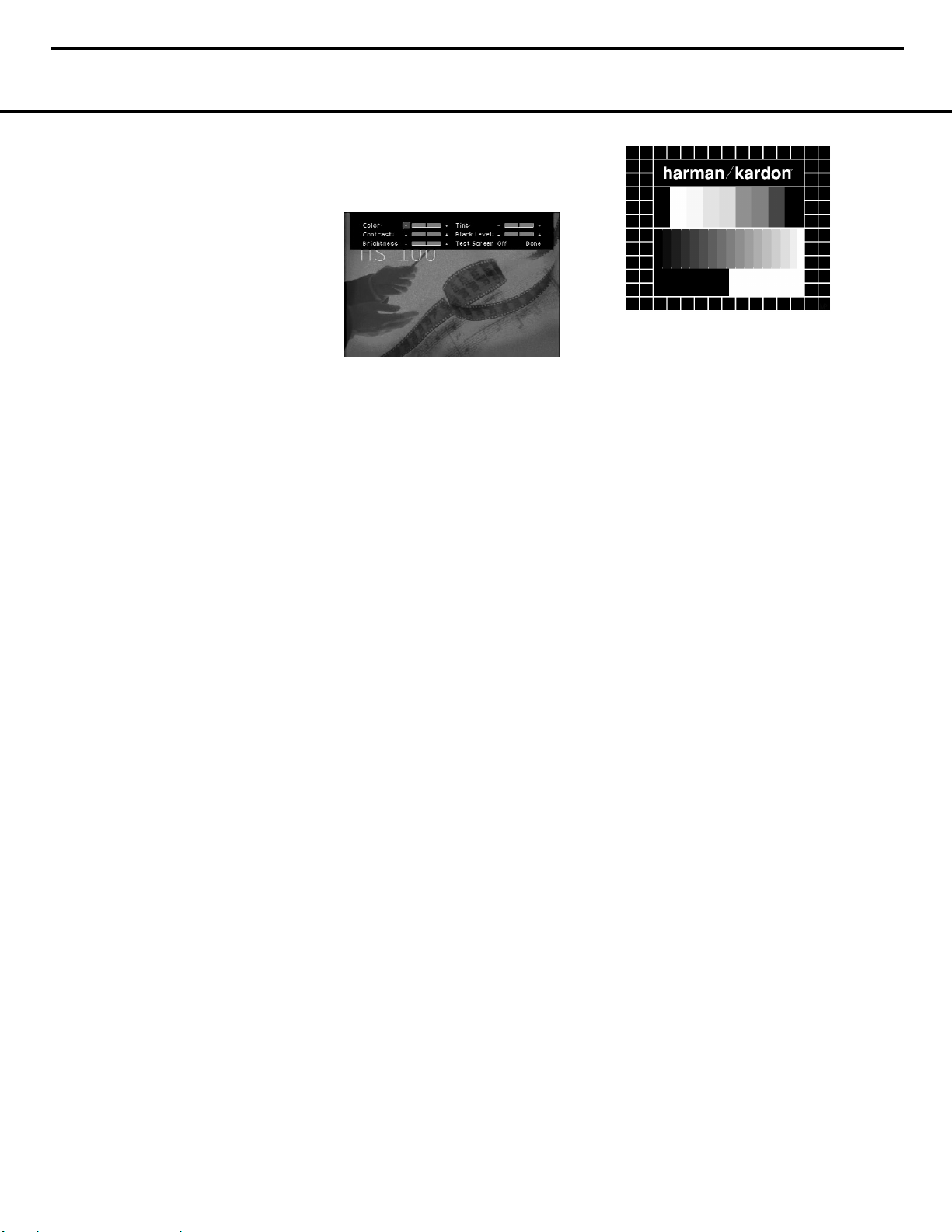
Video Setting
This menu establishes the DVD’s configuration for video
format settings such as aspect ratio and output scan.
As with all setup menus, press the OSD Button y
to activate the main menu screen, and then press the
M/N
Navigation Buttons k so that SETUP
is highlighted. Press the Enter Button z, and then
use the
M/N/K/L
Navigation Buttons k until
the VIDEO SETUP menu is highlighted within
a white outline, and press the Enter Button z
again. Finally, press the
M/N
Navigation Buttons
e once more to move the highlight to the Control
Settings ç side of the menu screen.
The following adjustments are available on the Video
Setup menu:
Aspect Ratio: This setting selects the aspect ratio
of video programming. Your choice should be made
according to the shape of your video display and your
personal preferences. Three choices are available:
• 16:9: If you have a widescreen (16:9) display, or a
display that has a widescreen mode, choose this setting. With this setting, the HS 100 will adjust the output for widescreen movies so that they fill the entire
screen in the proper aspect ratio. Note, however, that
in this setting a disc recorded in the 4:3 aspect ratio
will appear in the widescreen as a boxed image in
the center, with black columns on the left and right
side of the screen. Note that if the widescreen option
is chosen and a widescreen movie is played on a
conventional 4:3 aspect ratio set, the image will be
distorted due to vertical compression.
• 4:3 Letterbox: If you have a standard, 4:3 aspect
ratio video display, choose this setting if you wish to
see the entire frame of the movie as it is recorded
on the disc without any image cutoff at the left and
right sides. While this allows widescreen movies to
be shown in their entirety, they will occupy a smaller
portion of the screen and black “letterbox” bars may
appear at the top and bottom of the screen.
• 4:3 PanScan: If you have a standard, 4:3 aspect
ratio video display and prefer to have widescreen
movies displayed without the black bars at the top
and bottom of the screen, choose this option. Note,
however, that since most DVDs do not contain special “pan/scan” coding that allows the on-screen
image to follow the action, you may find that while
the image will fill the screen, the vertical spread will
cause it to be cropped at the left and right side.
Scan Type: This setting allows you to select
between progressive and interlaced scanning for the
Component Video Outputs ⁄ to maximize the
image resolution for the type of video display in use.
When all desired setup and configuration entries have
been made, press the OSD Button y to return
the player to normal operation and you are ready to
enjoy the finest in DVD or CD playback. Note that the
output at the S-Video ‚ and Composite Video ª
outputs will always be standard-rate video that is
compatible with any television set or video display.
Two choices are available:
16
HS100 Integrated Hom e Theater System harman/kardon
Page 17
SYSTEM SETUP
SYSTEM SETUP 15
• Progressive: Select this option if you have a video
display that is compatible with input sources of 480p
or greater. Displays labeled as “HDTV Ready,” including virtually all large-screen LCD and plasma displays, are compatible with progressive scan.
• Interlaced: Select this option when you are using
an older video display that has Y/Pr/Pb component
inputs, but which is not capable of displaying high
scan rate, or “HD,” signals.
Video Mode: This setting affects only the Component Video Outputs ⁄, and it controls how the
video signals are optimized for progressive scan display. In most cases, the “automatic” mode is your best
choice, as it senses whether the disc being played was
originally recorded on video or shot on film. However,
in some cases you may wish to compensate for errors
in the disc authoring that occur when the frame rate is
not properly maintained when films are converted to
video. Three choices are available:
• Auto: This is the recommended setting, as it lets the
HS 100 analyze the signals from the DVD and adjust
the output accordingly.
• Movie: Choose this option for optimal playback of
material that was shot on film, even though you are
viewing it on video via a DVD.
• Video: Choose this option for optimal playback of
material that was shot directly to video, such as concerts and sports programming.
Video Adjustments Menu
This menu allows you to adjust five key parameters
of the video signal to compensate for differences
between HS 100 and other video sources. You may
use either the HS 100’s built-in color bar test signal
or a test disc as the standard for the adjustments. To
ensure that your system is properly optimized, we
strongly recommend that you adjust your video display
using the display’s own controls before making any
changes to the HS 100’s output. Once the display is
properly calibrated with all settings on the HS 100 set
to their midpoint, use the controls on this menu to finetune the HS 100’s output.
Due to the nature of these settings, the navigation is
somewhat different from the HS 100’s other menus
and controls. The menu itself is called up in the same
way as the other menus. Press the OSD Button y
to activate the main menu screen, and then press the
K/L
Navigation Buttons k so that SETUP
is highlighted. Press the Enter Button z, and then
use the
M/N/K/L
Navigation Buttons k until
the VIDEO ADJUSTMENTS menu box
(which contains an icon with slider controls and the
word VIDEO, and is located at the bottom of the
column in the Submenus Area ∫) is highlighted
within a white outline. Then press Enter z again.
When you press Enter z the video adjustments will
appear inside a black bar at the top of the screen, with
either the video from a disc being played or the splash
screen shown on the rest of the screen.
To change any of the video adjustments shown at
the top of the screen, first press the
M/N/K/L
Navigation Buttons k so that the “+” to the right
of a parameter name is highlighted to increase the setting or “–” to the right of a parameter name is highlighted to decrease the setting. Then press the Enter
Button z to change the value as shown by the
number of blue lines to the left or right of the center
line. When only the dark center line is shown with no
blue lines, the setting is at the midpoint default value.
When adjusting the Black Level setting, note that the
adjustment available is to either have the setting at the
midpoint, which provides a full “0 to 100” black level
setting, or “full,” which complies with standards for
video with what is called “setup,” or a “7.5 to 100”
black level setting.
Changes to any of the settings may be made with
a test disc playing, or you may use the internal test signal by pressing the
M/N/K/L
Navigation Buttons
k until the word OFF is highlighted next to the
TEST SCREEN line. To activate the test signal,
press the Enter Button z and note that a special
combination test signal, including both color bars and
gray scale along with 100% black and white fields, will
be displayed. To recall the video controls, press the
OSD Button y and then navigate among the settings and make any necessary changes following the
steps in the previous paragraph.
Test Screen
With the test screen showing on your video display, the
following adjustments may be made:
• The proper color intensity setting on your TV.
• Proper color adjustments using the color bars, which
should be (left to right) black, white, yellow, cyan
(turquoise), green, magenta, red, blue, black.
• The proper color transition, seen as sharp
separation of the bars.
• The performance of the color circuits in your TV
(with “Video” signals); bar edges should show
no vertical crawling dots.
With the gray scale and the black/white fields below
the color bars, the brightness and contrast of your
screen can be adjusted.
TV Picture Adjustment With Test Screen
Brightness Adjustment:
1. Turn down the color control on your TV until the
color bars are visible in black and white.
2. Adjust the contrast to the lowest level where you still
can see all bars within the gray scale in the test picture separately and clearly.
3. Adjust the brightness so that the bars in the gray
scale are all visible. The bar furthest to the left has to
be as black as possible rather than gray but the next
gradation must clearly be distinct from it. All the bars
in the gray scale should be gradually and evenly
changing from black to white, left to right.
Contrast Adjustment:
1. Adjust the contrast on your TV until you see a bright
white bar in the lower right corner of the screen and
a deep-dark-black bar to the left. The optimal contrast setting will depend on your preference and the
surrounding light in the TV room.
2. If the brightness of the white bar no longer increases
when the contrast is turned up or the borders of the
white “harman/kardon” letters on top bloom (overlight) into the black areas (drastically decreasing
the sharpness of the type), the contrast has been
turned up too much. Reduce the contrast until these
effects disappear and the video still looks realistic.
3. If you are watching TV with customary surrounding
daylight, adjust the contrast so that a normal video
picture has about the same look as the surroundings
in your room. That way the eye is relaxed when
watching the TV picture. This contrast setting may be
reduced when the surrounding light is dimmed,
thereby usually improving the sharpness of a video
significantly.
4. The gray scale in the middle line needs to have
the same clear difference between each bar as
17
HS100 Integrated Hom e Theater System harman/kardon
Page 18

SYSTEM SETUP
16 SYSTEM SETUP
before the contrast adjustment. If not, go back to
“
Brightness Adjustment” and repeat Step 3 and then
“
Contrast Adjustment,” making only minor adjust-
ments each time for optimization.
Color and Tint Adjustment
1. When the brightness and contrast are set optimally,
adjust the color control to the level of your preference. Set the level where the colors look strong but
still natural, not overdone. If the color level is too
high, depending on the TV, some of the bars will
seem wider or the color intensity will not increase
while the control is turned up. Then the color control
must be reduced again. Ultimately, you also should
test the color intensity with a video – e.g., pictures
of natural faces, flowers, fruit and vegetables, and
other common natural articles for an optimal setting
of the color intensity.
2. Use the large white bar below the gray scale to
tweak the warmth of the picture. Every viewer has a
preference as to how the glow of the picture should
be. Some prefer a little colder picture, some a
warmer glow. The Tint function and the white bar
can be used to control this. Adjust the Tint to the
level where you feel the white color has the tone
you prefer.
18
HS100 Integrated Hom e Theater System harman/kardon
Page 19

BASIC OPERATION 19
BASIC OPERATION
Basic Operation
Once all connections have been made and the proper
configuration settings entered, you are ready to enjoy
the incredible listening and viewing experience made
possible by the HS 100. The pages that follow have all
the information needed to operate the HS 100, but the
following will help get you started with a basic overview.
• To turn on the HS 100, press the ON Button 0
on the remote or the Power On/Off Button on
the front panel to use the input that was in use when
the HS 100 was turned off.
• The HS 100 may also be turned on with direct
access of a specific input by pressing the Player
3, Radio 2, TV , Aux or Digital In
buttons on the remote.
• To select another input, press the Player 3,
Radio 2, TV , Aux or Digital In
buttons on the remote to choose the source.
• Turn the Volume Control A or press the Volume
Control Buttons on the remote to raise or
lower the volume.
• To temporarily silence the output, press the Mute
Button . Press the Mute Button again or
use the Volume Control A to return to normal
operation.
• Control over the settings for an individual input, such
as DVD playback and navigation or using the tuner is
done through a combination of the on-screen menus
and the remote control and front panel buttons.
Í To access the menu for a specific input, press
the OSD Button O, and then press the
‹/›
Navigation Buttons A until the desired source
(or the Setup menu for global system adjustments)
is highlighted in a light blue box. Note that the current source will be shown with a white line below
its name while you select another source. Press
the Enter Button P to select the highlighted
source.
Í Consult the pages in this manual pertaining to
each input source for the specific instructions
about using or configuring that source.
Surround Modes
One of the most important features of the HS 100 is
its ability to reproduce a multichannel surround presentation from digital sources, analog matrix-encoded
sources or traditional two-channel stereo program
material. In some cases, such as when a Dolby Digital
or DTS source with a 5.1 soundtrack is playing, surround mode selection is automatic, regardless of which
mode may be set in an input’s menu. In other cases,
the surround mode may be preset within the individual
input’s menu page. Each time the source is changed,
the HS 100 will automatically change to the Surround
Mode selected for that source.
When a DVD is playing, there may be a number of
different surround mode or audio options such as
a full 5.1 soundtrack in one language, a 2.0 soundtrack in different languages, or special commentary
or descriptive tracks for the vision-impaired. You may
select these tracks, when available, during DVD playback by pressing the Audio Button and then
using the
‹/› Navigation Buttons A to choose
from the options shown in the on-screen menu.
19
HS100 Integrated Hom e Theater System harman/kardon
Page 20

32 TROUBLESHOOTING
TROUBLESHOOTING
If you experience any of the following difficulties while
using the system, use this troubleshooting guide to help
you remedy the problem. Should any problem persist,
consult your authorized Harman Kardon dealer.
No power.
• Is the power cord firmly plugged into the power
outlet?
• The system’s processor may require a reset. In this
event, unplug the player from the power outlet briefly
and then plug it in again.
No picture.
• Check that the system is connected correctly and
securely.
• The video cable may be damaged. Replace it with a
new one.
• Make sure the system is connected to a video input
on the TV (see page 12).
• Make sure the TV is turned on.
• Make sure the correct video input on the TV is
selected for viewing with this system.
There is no sound, or volume is very low.
• Check that the speakers and components are
connected correctly and securely.
• Make sure that you have selected the correct source
on the system.
• Press MUTE on the remote control, if the words
“MUTE ON” are blinking on the front-panel display.
• The protective circuitry has been activated because of
a short circuit. Turn off the system, eliminate the short
circuit problem and turn on the power again.
• An audio interconnect cable is damaged. Replace it
with a new one.
• The system is in pause mode or in slow-motion play
mode, or fast forward or fast reverse. Press
N
to
return to normal play mode.
• Check the speaker settings (see page 16).
The audio channels are reversed.
• Check that the speakers and components are
connected correctly and securely.
Severe hum or noise is heard.
• Check that the speakers and components are
connected securely.
• Check that the connecting cords are away from a
transformer or motor or fluorescent light.
• The audio plugs are dirty. Wipe them with a cloth
slightly moistened with alcohol.
• Clean the disc.
The surround effect is difficult to hear when you
are playing a Dolby Digital soundtrack.
• Check to see whether the Dolby Digital mode is
turned on properly; otherwise, unload and load the
disc again.
• Check the speaker connections.
• Depending on the DVD disc, the output signal may at
times be mono or stereo even if the soundtrack is
recorded in Dolby Digital format.
The sound comes from the center speaker only.
• Depending on the disc, sound may sometimes come
from the center speaker only.This also applies to
mono recordings (from disc or any analog source),
when Pro Logic mode is selected. This is normal.
No sound is heard from the center speaker.
• Adjust center speaker volume (see pages 16).
No sound or only very low volume from the rear
speakers.
• Adjust the rear speaker volume (see page 16).
Radio stations cannot be tuned in.
• Check that the antenna is connected correctly.Adjust
the antenna and connect an external antenna if
necessary.
• No stations have been preset.
• The tuner mode is not selected, select the Radio
mode.
The remote does not function.
• Remove any obstacles between the remote control
and the system.
• Move the remote control closer to the system.
• Point the remote control at the remote sensor on the
front panel.
• Replace all the batteries in the remote control with
new ones if they are weak.
• Check that the batteries are loaded correctly.
The disc does not play.
• There is no disc inside. (“NO DISC” appears
on the front-panel display and the TV screen.) Insert
a disc.
• Insert the disc correctly with the playback side facing
down on the disc tray.
• Clean the disc.
• The system cannot play certain disc types
(see page 3).
• DVD with wrong region code (see page 11).
Playback stops automatically.
• Some discs include an auto pause signal. When
playing such a disc, the system stops playback at the
signal.
Track Skip or Direct Select with numeric buttons,
Search, Slow-Motion Play, Repeat Play or Program
Play, etc., cannot be done.
• Depending on the DVD, some of the above operations
may not be available (playback control with DVD).
The audio language cannot be changed when you
play a DVD.
• Multilingual sound is not recorded on the DVD.
• Changing the language for the sound is prohibited on
the DVD.
The subtitle language cannot be changed when
you play a DVD.
• Multilingual subtitles are not recorded on the DVD.
• Changing the language for the subtitles is prohibited
on the DVD.
The subtitles cannot be turned off when you play
a DVD.
• Depending on the DVD, you may not be able to turn
the subtitles off.
The angles cannot be changed when you play
a DVD.
• Multi-angles are not recorded on most DVDs.
• Change the angles when the angle mark appears on
the TV screen.
• Changing the angles is prohibited on some DVDs.
Please also refer to the Troubleshooting guide
contained in the HKTS 7 owner’s manual if you
suspect a problem with the speakers.
32 TROUBLESHOOTING
20
HS100 Integrated Hom e Theater System harman/kardon
Page 21
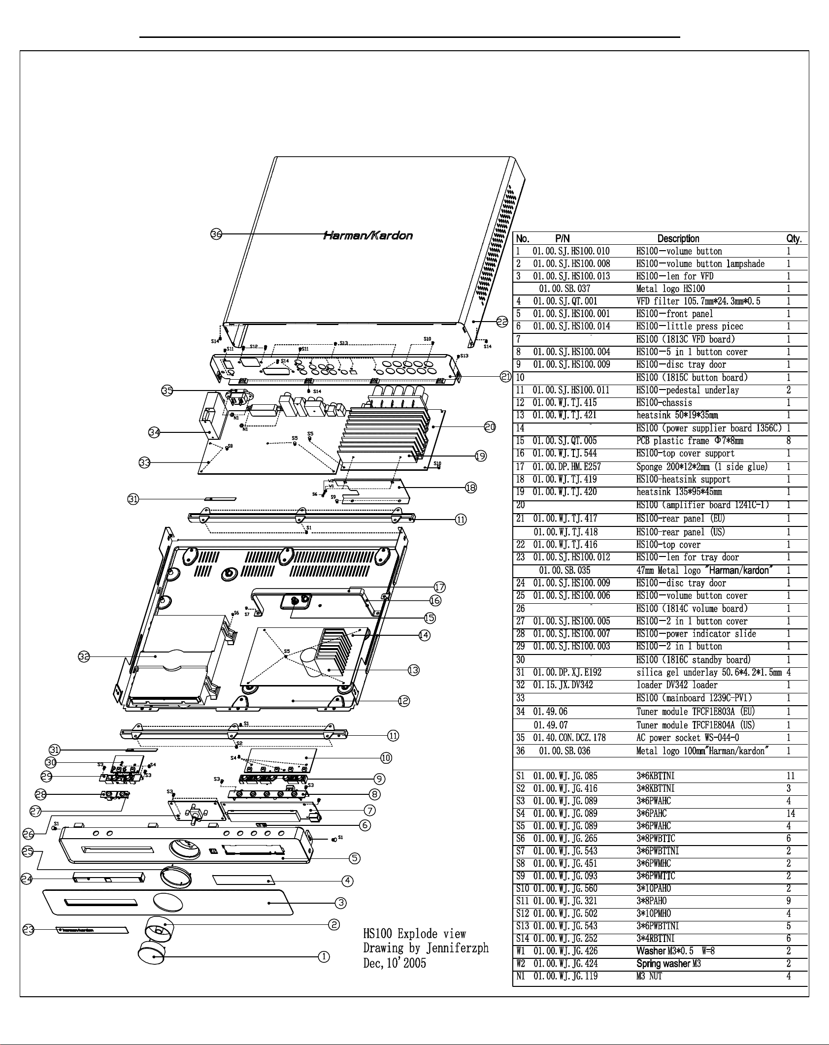
21
HS100 Integrated Hom e Theater System harman/kardon
Page 22
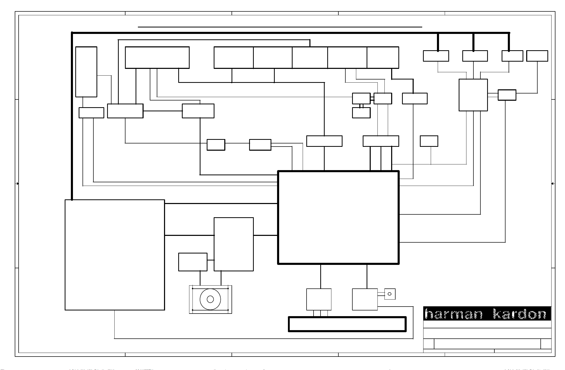
5
22
4
3
2
1
HS100 Integrated Hom e Theater System harman/kardon
VIDEO OUT
D D
TUNER
BU1924F
C C
RDS
AUXIN
TUNER IN
74HC4052
SCART
SCART IN
SCART CONTROL
L/R OUT
SWITCH
74HC164
RGB/Y/Pb/Pr CVBS&S-VIDEO AUXIN DOWNMIX
HEADPHONE
VIDEO OUTPUT
BH7862
LM833
L/R IN
CS5333
CLK
CLKL/R IN
DAC_IN
LR
NJM4558
LM4880
DIGITAL IN
LM833
WM8728
CLK
DATA3
74AHC158
SDA/SCL
RDS
28V 28V 28V
DDX2100 DDX2100 DDX2100
DDX8001 NJM4558
DIGITAL IN
24C64
SDA/SCL
DATA0/1/2
SUBWOOFER
POWER SUPPLY
+28V
+12V
CLK
-12V
B B
+D5V
+3.3V
+A5V
POWER SUPPLY
PV1
ATAPI
AMUTE
+S5V
SMPS
A A
5
AN8785SB
POWER/STANDBY
4
IR
LC75710
VFD
3
PIC16C56A
H arm an Kardon,N orthridge,C alifornia 91329,U SA
Title
H S 100 M AIN B O ARD 050725
Size D ocum entN um ber R ev
SYSTEM 3.43
B
of
2
Date: Sheet
124Tuesday,N ovem ber 22,2005
1
Page 23

23
HS100 Integrated Hom e Theater System harman/kardon
HS100 Electrical Parts List (120v)
MainBoard (1239C-PV1)
Part Number Description Qty Reference Designator
Resistors
01.57.R.2.E000J Resistor, chip 0603-0Ω ±5% 8 R1 R116 FB24 FB25 DR1 DR2 DR3 R143
01.57.R.2.E100J Resistor, chip 0603-10Ω±5% 9 R61 R62 R63 R114 3R2 3R4 DR4 DR5 DR6
01.57.R.2.E220J Resistor, chip 0603-22Ω±5% 6 R29 (R30) (R31) (R32) (R33) R202
01.57.R.2.E270J Resistor, chip 0603-27Ω±5% 2 R145 R146
01.57.R.2.E330J Resistor, chip 0603-33Ω±5% 5 R184 R185 R186 R189 R190
01.57.R.2.E560J Resistor, chip 0603-56Ω±5% 2 R149 R150
01.57.R.2.E750F Resistor, chip 0603-75Ω±1% 16 R9 R37 R39 R40 (R41) (R42) R43 (R44)
01.57.R.2.E820J Resistor, chip 0603-82Ω±5% 3 R182 R183 R187
01.57.R.2.E910J Resistor, chip 0603-91Ω±5% 1 AR10
01.57.R.2.E101J Resistor, chip 0603-100Ω±5% 5 R117 R137 R199 RR11 RR12
01.57.R.2.E151J Resistor, chip 0603-150Ω±5% 2 R89 R98
01.57.R.2.E1870F Resistor, chip 0603-187Ω±1% 2 R11 (R12)
01.57.R.2.E221J Resistor, chip 0603-220Ω±5% 4 RR6 RR7 RR8 RR9
01.57.R.2.E331J Resistor, chip 0603-330Ω±5% 2 R56 R67
01.57.R.2.E471J Resistor, chip 0603-470Ω±5% 4 R193 R211 (R212) R213
01.57.R.2.E681J Resistor, chip 0603-680Ω±5% 4 R55 R66 (3R3) (3R9)
01.57.R.2.E102J Resistor, chip 0603-1KΩ±5% 9 R78 R191 R192 R194 RR3
01.57.R.2.E122J Resistor, chip 0603-1.2KΩ±5% 1 R204
01.57.R.2.E1781F Resistor, chip 0603-1.78KΩ±1% 2 R57 R68
01.57.R.2.E222J Resistor, chip 0603-2.2KΩ±5% 1 R139
01.57.R.2.E272J Resistor, chip 0603-2.7KΩ±5% 5 (R17) (R18) (R19) (R20) AR11
01.57.R.2.E302J Resistor, chip 0603-3KΩ±5% 2 R81 R120
01.57.R.2.E392J Resistor, chip 0603-3.9KΩ±5% 1 (R195)
01.57.R.2.E472J Resistor, chip 0603-4.7KΩ±5% 23 R4 R7 R15 (R53) (R65) R93 R99 R106 R107
R45 R46 R47 R48 AR3 AR4 AR5 AR6
R173A1 R173B1 R173C1 R173D1
R108 R109 R110 R111 R113 AR2 AR12
(R4B1) (R5A1) (R121) (R122) (R123) AR7
R144
01.57.R.2.E4752F Resistor, chip 0603-4.75KΩ 1% 2 R54 R64
01.57.R.2.E562J Resistor, chip 0603-5.6KΩ±5% 2 R133 R197
01.57.R.2.E622J Resistor, chip 0603-6.2KΩ±5% 1 R128
01.57.R.2.E682J Resistor, chip 0603-6.8KΩ±5% 2 R86 R97
01.57.R.2.E752J Resistor, chip 0603-7.5KΩ±5% 6 R58 R69 R126 R196 R131 R134
01.57.R.2.E822J Resistor, chip 0603-8.2KΩ±5% 2 R90 R96
01.57.R.2.E103J Resistor, chip 0603-10KΩ±5% 52 (R2) (R3) (R5) (R6) (RR1) (RR2) (RR10)
01.57.R.2.E103F Resistor, chip 0603-10KΩ±1% 2 R130 R135
01.57.R.2.E153J Resistor, chip 0603-15KΩ±5% 3 R26 (R119) (R210)
01.57.R.2.E183J Resistor, chip 0603-18KΩ±5% 3 R124 R141 R201
01.57.R.2.E203J Resistor, chip 0603-20KΩ±5% 4 3R1 3R5 3R6 3R10
01.57.R.2.E273J Resistor, chip 0603-27KΩ±5% 1 R203
01.57.R.2.E333J Resistor, chip 0603-33KΩ±5% 1 R127
01.57.R.2.E473J Resistor, chip 0603-47KΩ±5% 1 R115
01.57.R.2.E683J Resistor, chip 0603-68KΩ±5% 1 R181
01.57.R.2.E104J Resistor, chip 0603-100KΩ±5% 5 (R28) R95 R102 (R129) 3R7
01.57.R.2.E105J Resistor, chip 0603-1MΩ±5% 4 (R14) (R138) R198 3R8
01.57.R.3.E2R2J Resistor, chip 0805-2.2Ω±5% 2 R147 R148
01.57.R.8.EP3304 Resistor, thick film chip network 33Ω*4 ±5% 4 RN13 RN16 RN17 RN18
01.57.R.8.EP0824 Resistor, thick film chip network 82Ω*4 ±5% 1 RN12
01.57.R.8.EP4734 Resistor, thick film chip network 47KΩ*4 ±5% 1 RN2
01.57.R.C.ED750 Fixed carbon film RT1/4W-75Ω 1 R75
01.57.R.Y.270 Zinc oxide varistor, for ESD AVR-M1608C270MTABB 2 ESD10 ESD11
(R16) (R21) (R22) (R23) (R24) (R27) (R34)
R35 (R36) R38 R59 (R60) (R71) R72 (R79)
R80 R84 (R85) R112 (R118) (R125) R132
R151 R152 R153 R154 R155 R158 R159
R167 R172 R175 (R176) (R177)
(R178) R180 R188 (R205) (R206) (R207)
(R208) R209 (R215) R156 R157
Page 24

24
HS100 Integrated Hom e Theater System harman/kardon
Part Number Description Qty Reference Designator
MainBoard (1239C-PV1)
Capacitors
01.54.CS.2.E6P8X Capacitor,multilayer ceramic, chip 0603-6.8P X7R 1 C24
01.54.CS.2.E100N Capacitor,multilayer ceramic, chip 0603-10P NPO±5%/50V 4 (C21) C124 C125 (C151)
01.54.CS.2.E200N Capacitor,multilayer ceramic, chip 0603-20P NPO±5%/50V 6 (2C4) (2C8) (C31) (C35) (C37) (C43)
01.54.CS.2.E220N Capacitor,multilayer ceramic, chip 0603-22P NPO±5%/50V 3 (C22) (C23) (C47)
01.54.CS.2.E330N Capacitor,multilayer ceramic, chip 0603-33P NPO±5%/50V 3 (C91) (C95) C119
01.54.CS.2.E470N Capacitor,multilayer ceramic, chip 0603-47P NPO±5%/50V 8 (C20) C81 C83 C108 C115 C60 C61 C87
01.54.CS.2.E510N Capacitor,multilayer ceramic, chip 0603-51P NPO±5%/50V 2 (C38) (C42)
01.54.CS.2.E201N Capacitor,multilayer ceramic, chip 0603-200P NPO±5%/50V 2 C59 C74
01.54.CS.2.E221N Capacitor,multilayer ceramic, chip 0603-220P NPO±5%/50V 1 C109
01.54.CS.2.E271N Capacitor,multilayer ceramic, chip 0603-270P NPO±5%/50V 1 C90
01.54.CS.2.E561N Capacitor,multilayer ceramic, chip 0603-560P NPO±5%/50V 3 (C26) (C72) C94
01.54.CS.2.E102X Capacitor,multilayer ceramic, chip 0603-102 X7R±10%/50V 1 (C139)
01.54.CS.2.E152X Capacitor,multilayer ceramic, chip 0603-152 X7R±10%/50V 1 C110
01.54.CS.2.E562X Capacitor,multilayer ceramic, chip 0603-562 X7R±10%/50V 1 C116
01.54.CS.2.E103Y Capacitor,multilayer ceramic, chip 0603-103 Y5V-20+80%/50V 5 C82 C84 (C114) (C158) (C161)
01.54.CS.2.E183X Capacitor,multilayer ceramic, chip 0603-183 X7R±10%/50V 3 (C122) (C28) (C36)
01.54.CS.2.E333X Capacitor,multilayer ceramic, chip 0603-333 X7R±10%/50V 1 (C112)
01.54.CS.2.E104Y Capacitor,multilayer ceramic, chip 0603-104 Y5V-20+80%/50V 122 CB1 CB2 CB3 CB4 CB5 CB6 CB7 CB8 CB9
CB10 CB11 CB12 CB13 CB14 CB15 CB16
CB17 CB18 CB19 CB20 CB21 CB22 CB23
CB24 CB25 CB26 CB27 CB28 CB29 CB30
CB31 CB32 CB33 CB34 CB35 CB36 CB37
CB38 CB39 CB40 CB41 CB42 CB43 CB44
CB45 CB46 CB47 CB48 CB49 CB50 CB51
CB52 CB53 CB54 CB55 CB56 CB57 CB58
CB59 CB60 CB61 CB62 CB63 CB64 CB65
CB66 CB67 CB68 CB69 CB70 CB71 CB72
CB73 CB74 CB75 CB76 CB77 CB78 CB79
CB80 CB81 CB82 CB83 CB84 CB85 CB86
CB87 CB88 CB89 CB90 CB91 CB92 CB93
CB94 CB95 CB96 CB97 CB98 CB99 CB102
CB103 CB104 CB105 CB106 CB107 CB108
CB110 CB111 CB112 CB113 CB114 CB115
CB116 CB117 CB135 CB120 CB121 CB122
CB131 CB132 CB134 C85
01.54.CS.2.E105Y Capacitor,multilayer ceramic, chip 0603-105 Y5V-20+80%/10V 3 (C150) (C156) (C157)
01.54.CS.3.E101N Capacitor,multilayer ceramic, chip 0805-100P NPO±5%/50V 2 C54 C64
01.54.CS.3.E681N Capacitor,multilayer ceramic, chip 0805-680P NPO±5%/50V 2 (C67) (C68)
01.54.CS.3.E102N Capacitor,multilayer ceramic, chip 0805-102 NPO±5%/50V 2 C56 C69
01.34.CL.D.E1U50VC Capacitor, AL.electrolytic CD110-1UF/50V 5*11 9 C41 C44 EC22 EC23 EC24 EC25 3C1 3C2
01.34.CL.D.EV2U250VC Capacitor, AL.electrolytic CD110-2.2UF/50V 5*11 1 C93
01.34.CL.D.E4U750VC Capacitor, AL.electrolytic CD110-4.7UF/50V 5*11 2 EC43 EC44
01.34.CL.D.E10U16VC Capacitor, AL.electrolytic CD110-10UF/16V 5*11 12 EC15 EC16 EC20 EC21 EC28 EC29 EC33
01.34.CL.D.E22U16VC Capacitor, AL.electrolytic CD110-22UF/16V 5*11 3 C27 C40 C46
01.34.CL.D.E47U16VC Capacitor, AL.electrolytic CD110-47UF/16V 5*11 24 C6 C14 C15 C29 C30 C49 C51 C58 C66
01.34.CL.D.E100U10VD Capacitor, AL.electrolytic CD110-100UF/10V 5*12 7 C11 C25 C39 C45 EC1 EC2 EC32
01.34.CL.D.E100U25VD Capacitor, AL.electrolytic CD110-100UF/25V 6.3*12 4 C17 C76 EC30 EC31
01.34.CL.D.E100U50VD Capacitor, AL.electrolytic CD110-100UF/50V 8*12 2 C4 C7
01.34.CL.D.E220U16VD Capacitor, AL.electrolytic CD110-220UF/16V 6.3*12 18 EC3 EC4 EC5 EC6 EC7 EC8 EC11 EC40
01.34.CL.D.E330U16VD Capacitor, AL.electrolytic CD110-330UF/16V 6.3*12 2 C52 C53
01.34.CL.D.E470U16VD Capacitor, AL.electrolytic CD110-470UF/16V 8*12 3 C5 C13 C18
01.34.CL.D.EV1500U6V3 Capacitor, AL.electrolytic CD110-1500UF/6.3V 8*17 1 C48
Semiconductors
01.41.D.PD.IN4148 Diode IN4148 DIP 5 D15 D17 D18 D19 D20
01.41.D.PD.5393 Diode IN5393 DIP 3 D24 D26 D27
01.41.D.PS.LL4148 Diode LL4148 SMD 2 D16 D25
3C3
EC34 EC35 EC36 EC39 C12
C75 C79 C80 C99 C100 C101 EC9 EC10
EC12 EC13 EC14 EC19 EC27 EC42 EC45
EC41 C1 C3 C8 C16 C19 C34 C77 3C6 3C7
Page 25

25
HS100 Integrated Hom e Theater System harman/kardon
Part Number Description Qty Reference Designator
MainBoard (1239C-PV1)
01.42.Q.S.9014 Transistor C9014 SMD 7 Q3 Q4 Q5 Q6 Q7 Q8 Q13
01.42.Q.S.8050 Transistor KTC8050 SMD 6 Q23 Q24 Q25 2Q4 2Q5 Q20
01.42.Q.S.8550 Transistor S8550 SMD 5 Q1 Q2 Q12 Q17 Q26
01.42.Q.S.EDTC343 Transistor DTC343TKT146 SMD 4 Q9 Q10 (Q19) (Q27)
01.42.Q.S.DTA114 Transistor DTA114EKAT146 SMD 1 Q22
01.42.Q.S.E3018 Transistor 2SK3018T106 SMD 1 Q18
01.42.Q.D.8050 Transistor 8050 DIP 1 Q16
01.42.Q.D.8550 Transistor 8550 DIP 1 Q15
01.44.IC.S.8785 IC, Panasonic, Motor Driver AN8785SB, HSOP042 1 U1
01.44.IC.S.018EZ01 IC, Sharp, Voltage Regulator O18EZ01, PQ025 1 U2
01.44.IC.D.79L05 IC, NS, Voltage Regulator 79L05, 3P, TO-92 1 U3
01.44.IC.S.3390 IC, Amlogic, decoder AML3390DTS, 208P, PQFP 1 U4
01.44.IC.S.74HC164 IC, TI, 8-bit serial-in/ parallel-out
shift register
01.44.IC.S.29LV160DB IC, AMD, Flash AM29LV160DB-90EC, 48P, TSOP48 1 U7(burn-in firmware)
01.46.IC.27C02 IC, Atmel Servo FLASH. AT27C020-70ZC, PLCC 1 U8(burn-in servo code)
01.44.IC.S.103S47 IC, Panasonic, Servo chip MN103S47JRB, 176P, QFP 1 U9
01.46.IC.641620 IC, Hyundai, SDRAM HY57V641620HGT-7, 54P, TSOP54 1 (U6)
01.44.IC.S.4558 IC, JRC, Pre-amp NJM4558, 8P, SOP 1 U12
01.44.IC.S.833 IC, NS, Pre-amp LM833, 8P, SOP 2 U11 U20
01.44.IC.S.7862 IC, Rohm, Video Buffer BH7862FS, 32P, SSOP-A32 1 U14
01.44.IC.S.4880 IC, NS, Audio Power Amplifier LM4880, 8P, SOP8 1 3U2
01.44.IC.S.24C64 IC, Atmel, EEPROM AT24C64, 8P, SOP 1 U15(burn-in EU or US firmware)
01.44.IC.S.8728 IC, Wolfson, Audio DAC WM8728, 20P, SSOP20 1 U16
01.44.IC.D.78L05 IC, NS, Voltage Regulator 78L05, 3P, TO-92 3 U10 U13 U19
01.44.IC.S.4052 IC, NS, Analog Multiplexer CD4052, 16P, SOP16 1 U21
01.44.IC.S.74HC158 IC, TI, Data selectors 74HC158, 16P, SOP16 1 U22
01.44.IC.S.5333 IC, Crystal, A/D Converter CS5333, 16P, TSSOP16 1 U23
01.44.IC.D.L7809 IC, NS, Voltage Regulator L7809, 3P, TO-220 1 U24
01.44.IC.S.1924 IC, Rohm, RDS decoder BU1924, 16P, SOP16 1 U25
01.46.IC.7414 IC, Philips, Hex inverting Schmitt
trigger
74HC164, 14P, SO14 1 U5
74HCT14, 14P, SO14 1 U26
Miscellaneous
01.13.L.L.S.E002 Inductor, multilayer ceramic, chip 0603-10UH 1 R136
01.13.L.L.S.E117 Inductor, multilayer ceramic, chip 0805-0.39UH 1 (L18)
01.13.L.L.S.E118 Inductor, multilayer ceramic, chip 0805-0.68UH 2 (L16) (L17)
01.13.L.R.068 Tuner 19k filter EJ219 2 Z1 Z2
01.13.L.Z.ESA300 Bead, chip 0603-300Ω 1 R74
01.13.L.Z.ESA50 Bead, chip 0603-50Ω 11 FB10 FB11 FB12 (FB13) (FB14) (FB15) FB26
01.13.L.Z.ESB50 Bead, chip 0805-50Ω 37 FB1 FB2 FB4 FB6 FB7 FB8 FB27 FB28
01.13.L.Z.ED50A Bead, leaded fixed 50Ω(3.5*6.0*0.8) 4 FB3 FB5 FB9 FB30
01.13.L.Z.EHFSF Bead, without pin HFSFBB3.5*6*0.8 2 match with Y1
01.00.JZ.E27000 Fundamental. Oscillator 27.000MHZ-49S-20P 1 Y1
01.00.JZ.E33868 Fundamental. Oscillator 33.8688MHZ-49S-20P 1 Y2
01.00.JZ.E4332 Fundamental. Oscillator 4.332MHz-49S-20P 1 Y3
01.40.CON.S05.E007 Connector FPC-0.5-24P (upward touching) 1 CN3
01.43.004 Jack, Sharp, Fiber optic input jack GP1FA513RZ, In-line Package 1 CN2
01.40.CON.DCZ.062 Connector 1.25-11P 1 CN1
01.40.CON.DPH.023 Connector PH-5A, 5P, In-line Package 2 CN4 CN6
01.40.CON.DPH.027 Connector PH-6A, 6P, In-line Package 1 CN5
01.40.CON.DPH.041 Connector PH-9A, 5P, In-line Package 1 CON6
01.40.CON.DPH.001 Connector PH-10A, 6P, In-line Package 1 CON7
01.40.CON.DCZ.142 Video&S-Video output jack SAV-01 (yellow) 1 CON8
01.40.CON.DCZ.183 Component Video output jack AV3-8.4-13G 1 CON4
01.40.CON.DCZ.173 Audio output&input jack AV4-8.4-5 1 CON9
01.40.CON.DCZ.123 Coaxial output jack AV1-8.4-6G (orange) 1 CON5
01.40.CON.S10.E024 Connector 1.0-16P 1 CON1
FB31 FB32 FB33 (FB34)
FB29 L1 L2 L3 L4 L5 L6 L7 (L8) L9 L10 L11
L12 L13 L14 L15 L19 L20 L21 L22 (L23) L24
L25 L26 L28 L29 L30 L31 L33
Page 26

A
A
A
26
HS100 Integrated Hom e Theater System harman/kardon
Part Number Description Qty Reference Designator
MainBoard (1239C-PV1) only for US version
01.57.R.2.E472J
01.57.R.2.E822J
01.57.R.C.EC302
01.57.R.Y.270
01.40.CON.DCZ.182
Resistor, chip
Resistor, chip
Fixed carbon film
Zinc oxide varistor, for ESD
Connector
0603-4.7KΩ±5% 4
0603-8.2KΩ±5% 2
RT1/6W-3KΩ 2
VR-M1608C270MTABB 2
V2-8.4-7B/PB 1
R92 R101 R104 R105
R88 R94
hand-make solder
ESD4 ESD5
CON3
MainBoard (1239C-PV1) only for EU version
01.57.R.2.E750F
01.57.R.2.E202J
01.57.R.2.E332J
01.57.R.2.E472J
01.57.R.2.E822J
01.57.R.2.E153J
01.57.R.C.ED151
01.57.R.C.ED102
01.57.R.Y.270
01.54.CS.2.E104Y
01.13.L.Z.ESA50
01.42.Q.S.EDTC343
01.40.CON.DCZ.181 SCART Connector CS-101 with shield 1
Resistor, chip
Resistor, chip
Resistor, chip
Resistor, chip
Resistor, chip
Resistor, chip
Fixed carbon film
Fixed carbon film
Zinc oxide varistor, for ESD
Capacitor, multilayer ceramic, chip
Bead, chip
Transistor
0603-75Ω±1% 4
0603-2KΩ±5% 2
0603-3.3KΩ±5% 6
0603-4.7KΩ±5% 3
0603-8.2KΩ±5% 4
0603-15KΩ±5% 1
RT1/4W-150Ω 1
RT1/4W-1KΩ 2
VR-M1608C270MTABB 6
0603-104 Y5V-20+80%/50V 3
0603-50Ω 6
DTC343TKT146 SMD 3
R49 R50 R51 R52
2R11 2R12
2R3 2R4 2R6 2R7 2R8 2R9
R104 R105 2R10
R88 R94 R92 R101
(2R13)
2R5
2R1 2R2
ESD4 ESD5 ESD6 ESD7 ESD8 ESD9
CB100 CB101 CB109
FB18 FB19 FB20 FB21 FB22 FB23
2Q1 2Q2 2Q3
CON3
Amplifier Board (1241C-1)
Resistors
01.57.R.2.E000J Resistor, chip 0603-0Ω ±5% 6 RR1 RR2 RR3 RR7 RR8 RR9
01.57.R.2.E151J Resistor, chip 0603-150Ω±5% 1 R11
01.57.R.2.E271J Resistor, chip 0603-270Ω±5% 1 R15
01.57.R.2.E102J Resistor, chip 0603-1KΩ±5% 2 R8 R12
01.57.R.2.E152J Resistor, chip 0603-1.5KΩ±5% 3 R7 R9 R10
01.57.R.2.E332J Resistor, chip 0603-3.3KΩ±5% 1 AR5
01.57.R.2.E103J Resistor, chip 0603-10KΩ±5% 7 R3 R4 R5 R6 AR9 AR16 AR23
01.57.R.2.E473J Resistor, chip 0603-47KΩ±5% 1 R13
01.57.R.4.E4R7J Resistor, chip 1206-4.7Ω±5% 10 AR6 AR7 AR10 AR11 AR13 AR14 AR17
01.57.R.4.E150J Resistor, chip 1206-15Ω±5% 5 AR8 AR12 AR15 AR19 AR22
AR18 AR20 AR21
Capacitors
01.54.CS.2.E270N Capacitor,multilayer ceramic, chip 0603-27P NPO±5%/50V 1 C2
01.54.CS.2.E101N Capacitor,multilayer ceramic, chip 0603-100P NPO±5%/50V 1 C5
01.54.CS.2.E221N Capacitor,multilayer ceramic, chip 0603-220P NPO±5%/50V 1 AC22
01.54.CS.2.E102X Capacitor,multilayer ceramic, chip 0603-102 X7R±10%/50V 2 AC6 C4
01.54.CS.2.E153Y Capacitor,multilayer ceramic, chip 0603-153 Y5V-20+80%/50V 1 C1
01.54.CS.2.E104Y Capacitor,multilayer ceramic, chip 0603-104 Y5V-20+80%/50V 42 (CB2) CB3 (CB4) (AC1) (AC2) (AC3)
01.54.CS.3.E102N Capacitor,multilayer ceramic, chip 0805-102 NPO±5%/50V 10 (CB7) (CB8) (CB9) (CB10) (CB11) (CB12)
01.54.CS.2.E122X Capacitor,multilayer ceramic, chip 0603-122 X7R±10%/50V 1 AC20
01.54.CS.3.E104Y Capacitor,multilayer ceramic, chip 0805-104 Y5V+80-20%/50V 20 AC28 AC33 AC38 AC41 AC43 AC47 AC52
01.54.CS.4.E470 Capacitor,multilayer ceramic, chip 1206-470P X7R±10%/50V 5 AC30 AC46 AC58 AC74 AC86
01.33.CT.C1U50V Solid Electrolyte Tantalum Chip
Capacitor
01.33.CT.B22U10V Solid Electrolyte Tantalum Chip
Capacitor
01.34.CL.D.E68463J Box-type metallized poly film cap 0.68uF 63V J NPO P=5 5 AC36 AC49 AC64 AC77 AC92
01.34.CL.D.E10U25VC Capacitor, AL.electrolytic CD110-10UF/25V 5*11 1 EC5
C-1UF-50V 5 AC37 AC44 AC65 AC72 AC93
B-22UF-10V 2 AC11 AC24
(AC4) (AC7) (AC8) (AC9) (AC10) (AC13)
(AC14) (AC15) AC18 (AC19) AC23 AC25
(AC26) (AC27) (AC29) AC31 AC32 AC40
AC42
AC50 AC51 AC55 AC59 AC60 AC68 AC70
AC78 AC79 AC83 AC87 AC88 AC98 AC96
(CB13) (CB14) (CB15) (CB16)
AC54 AC56 AC61 AC66 AC69 AC71 AC75
AC80 AC82 AC84 AC89 AC94 AC97
Page 27

27
HS100 Integrated Home Theater System harman/kardon
Part Number Description Qty Reference Designator
Amplifier Board (1241C-1)
01.34.CL.D.E100U16VC Capacitor, AL.electrolytic CD110-100UF/16V 5*11 3 EC1 EC2 AC12
01.34.CL.D.E1000U50V Capacitor, AL.electrolytic CD288H-1000UF/50V 13*25 3 AC34 AC62 AC90
01.34.CL.D.E47U16VC Capacitor, AL.electrolytic CD110-47UF/16V 5*11 2 EC3 EC4
Semiconductors
01.44.IC.S.2100 IC, Apogee, Power Device DDX2100, 36P 3 AU1 AU2 AU3
01.44.IC.S.8001 IC, Apogee, Digital Audio
Processor
01.44.IC.S.3522 IC, Analogic, Microprocessor Reset
Circuit
01.42.Q.S.EDTC343 Transistor DTC343TKT146 SMD 1 Q2
01.44.IC.S.4558 IC, JRC, Pre-amp NJM4558, 8P, SOP 1 U4
01.44.IC.S.9161A IC, RichTek, Voltage Regulator RT9161/A-33, 4P, SOT-89 1 U1
01.41.D.PS.LL4148 Diode LL4148 SMD 2 D4 D5
Miscellaneous
01.13.L.Z.ESB50 Bead, chip 0805-50Ω 1 FB1
01.13.L.Z.ESB300 Bead, chip 0805-300Ω 2 L2 L3
01.13.L.L.D.127 Magnetic shielding Inductor 983BN-1003-15UH 10 LL1 LL2 LL3 LL4 LL5 LL6 LL7 LL8 LL9 LL10
01.00.FZ.ZZ.009 Jumper 5mm 1 Q1
01.40.CON.DCZ.129 Connector Vertical VH three holes two pins 1 CN1
01.40.CON.S10.E024 Connector 1.0-16P 1 CN5
01.40.CON.DCZ.172 Sub output jack AV1-8.4-6G (Purple) 1 CN3
01.40.CON.DCZ.184 Amplifier output jack WP10-23-3 1 CN4
01.40.CON.DPH.058 Connector PH-5A 1 CN6
DDX8001, 64P, TQFP64 1 U3
AAT3522IGY-3.08, 3P, SST3 1 U2
Front Panel Board - VFD board (1813C)
01.57.R.3.E472J Resistor, chip 0805-4.7KΩ±5% 1 3R35
01.57.R.3.E103J Resistor, chip 0805-10KΩ±5% 3 3R1 3R2 3R14
01.57.R.3.E203J Resistor, chip 0805-20KΩ±5% 1 3R13
01.57.R.Y.270 Zinc oxide varistor, for ESD AVR-M1608C270MTABB 2 ESD1 ESD2
01.54.CS.3.E300N Capacitor,multilayer ceramic, chip 0805-30P NPO±5%/50V 1 3C18
01.54.CS.3.E560N Capacitor,multilayer ceramic, chip 0805-56P NPO±5%/50V 2 C90 C91
01.54.CS.3.E101N Capacitor,multilayer ceramic, chip 0805-100P NPO±5%/50V 3 3C4 3C19 3C20
01.54.CS.3.E473X Capacitor,multilayer ceramic, chip 0805-473 X7R±10%/50V 2 3C21 3C22
01.54.CS.3.E104Y Capacitor,multilayer ceramic, chip 0805-104 Y5V+80-20%/50V 1 3CB1
01.54.CS.3.E225Y Capacitor,multilayer ceramic, chip 0805-225 Y5V-20+80%/16V 1 3CB5
01.34.CL.D.EX100U16VB Capacitor, AL.electrolytic CD11X-100UF/16V 6.3*7 1 3C5
01.41.D.PS.LL4148 Diode LL4148 SMD 1 3D12
01.42.Q.S.8050 Transistor KTC8050 SMD 1 3Q2
01.42.Q.S.8550 Transistor S8550 SMD 1 3Q1
01.44.IC.S.75710 IC, Sanyo, VFD driver LC75710 1 3U2
01.44.IC.D.38B17 IR receiver HL38B17, DIP 1 3IR1
01.13.L.Z.ESB220 Bead, chip 0805-220Ω 2 FB9 FB10
01.13.L.Z.ESB50 Bead, chip 0805-50Ω 1 FB5
01.13.L.L.S.E007 Inductance, chip 0805-10UH 1 FB11
190-0001301F-0120 VFD VFD22-1301F 1 VFD
01.40.CON.DCZ.219 Headhpone jack CKX-3.5-12 1 3J5
01.40.CON.DPH.023 Connector PH-5A 1 3J3
01.40.CON.DPH.031 Connector PH-7A 1 3J10
01.40.CON.DPH.041 Connector PH-9A 2 3J11 3J12
Front Panel Board - Volume board (1814C)
01.57.R.3.E000J Resistor, chip 0805-0Ω ±5% 2 3R15 3R21
01.57.R.3.E101J Resistor, chip 0805-100Ω±5% 2 3R17 3R19
01.57.R.3.E301J Resistor, chip 0805-300Ω±5% 4 3R6 3R28 3R29 3R30
01.57.R.3.E222J Resistor, chip 0805-2.2KΩ±5% 1 3R24
01.57.R.3.E103J Resistor, chip 0805-10KΩ±5% 3 3R20 3R22 3R23
01.57.R.3.E104J Resistor, chip 0805-100KΩ±5% 1 3R18
01.54.CS.3.E123X Capacitor,multilayer ceramic, chip 0805-123 X7R±10%/50V 1 3CB8
01.54.CS.3.E104Y Capacitor,multilayer ceramic, chip 0805-104 Y5V+80-20%/50V 1 3CB4
Page 28

28
HS100 Integrated Hom e Theater System harman/kardon
Part Number Description Qty Reference Designator
Front Panel Board - Volume board (1814C)
01.54.CS.3.E105Y Capacitor,multilayer ceramic, chip 0805-105 Y5V-20+80%/16V 1 3CB7
01.34.CL.D.E47U10V2B Capacitor, AL.electrolytic CD11X-47UF/10V 4*7 1 3C3
01.34.CL.D.E22U35VB Capacitor, AL.electrolytic CD11X-22UF/35V 5*7(105℃) 8 3C1 3C8 3C9 3C10 3C11 3C12 3C14 3C15
01.34.CL.D.E100U35VD Capacitor, AL.electrolytic CD110-100UF/35V 6.3*12 2 3C6 3C7
01.34.CL.D.E22U50VB Capacitor, AL.electrolytic CD11X-22UF/50V 6.3*7 1 3C13
01.41.D.PS.LL4148 Diode LL4148 SMD 9 3D1 3D2 3D3 3D4 3D5 3D6 3D7 3D8 3D10
01.41.D.WD.6V2 Zener Diode 6.2V 1 3DZ1
01.44.IC.S.9022
01.36.VR.20K Volume encoder ED1612-24-24HC-F20(Z) 1 CON1
01.41.D.FD.65018 Diode, color is blue HFBA65018CP Ф5 4 3LD1 3LD2 3LD3 3LD4
01.40.CON.DPH.031 Connector PH-7A 1 3J9
Front Panel Board - Button board (1815C)
01.57.R.3.E101J Resistor, chip 0805-100Ω±5% 1 3R38
01.57.R.3.E471J Resistor, chip 0805-470Ω±5% 1 3R7
01.57.R.3.E102J Resistor, chip 0805-1KΩ±5% 1 3R4
01.57.R.3.E472J Resistor, chip 0805-4.7KΩ±5% 7 3R3 3R25 3R26 3R27 3R31 3R34 3R36
01.57.R.3.E153J Resistor, chip 0805-15KΩ±5% 1 3R5
01.54.CS.3.E220N Capacitor,multilayer ceramic, chip 0805-22P NPO±5%/50V 2 3C16 3C17
01.54.CS.3.E821N Capacitor,multilayer ceramic, chip 0805-820P NPO±5%/50V 2 3C23 3C24
01.54.CS.3.E104Y Capacitor,multilayer ceramic, chip 0805-104 Y5V+80-20%/50V 2 3CB3 3CB6
01.54.CS.3.E225Y Capacitor,multilayer ceramic, chip 0805-225 Y5V-20+80%/16V 1 3CB2
01.34.CL.D.E47U10V2B Capacitor, AL.electrolytic CD11X-47UF/10V 4*7 1 3C2
01.41.D.PS.LL4148 Diode LL4148 SMD 1 3D9
01.42.Q.S.8550 Transistor S8550 SMD 1 3Q5
01.00.JZ.E04000 Fundamental. Oscillator 4.000MHZ-49S-22P 1 3Y1
01.39.SW.QC.D665 Touch switch 6*6*5 5 3K2 3K3 3K4 3K5 3K6
01.44.IC.D.16C56A IC, Microchip, MCU PIC16C56A-04/P 1 3U1 (burn-in MCU code)
01.40.CON.DPH.060 Connector PH-7A 1 3J7
01.40.CON.DPH.041 Connector PH-9A 1 3J8
01.40.CON.DTJ.006 Connector TJC3-3A 1 3J4
IC, NS, Vacuum Fluorescent
Display Filament Driver
LM9022, 8P, SO8 1 3U3
Front Panel Board - Standby board (1816C)
01.57.R.3.E621J Resistor, chip 0805-620Ω±5% 2 3R11 3R111
01.57.R.3.E202J Resistor, chip 0805-2KΩ±5% 2 3R12 3R122
01.57.R.3.E472J Resistor, chip 0805-4.7KΩ±5% 2 3R9 3R10
01.41.D.PS.LL4148 Diode LL4148 SMD 2 3D14 3D15
01.42.Q.S.8050 Transistor KTC8050 SMD 1 3Q3
01.42.Q.S.8550 Transistor S8550 SMD 1 3Q4
01.41.D.FD.503 Diode, color is blue & orange HFT503CPB0 2 3LCD1 3LCD2
01.39.SW.QC.D665 Touch switch 6*6*5 2 3K1 3K7
01.40.CON.DPH.060 Connector PH-7A 1 3J6
Power Supply Board (1356C)
Resistors
01.57.R.C.EC100 Fixed carbon film RT1/6W-10Ω 4 R3 R5 R23 R25
01.57.R.C.EC101 Fixed carbon film RT1/6W-100Ω 1 R16
01.57.R.C.EC221 Fixed carbon film RT1/6W-220Ω 2 R13 R14
01.57.R.C.EC331 Fixed carbon film RT1/6W-330Ω 1 R30
01.57.R.C.EC102 Fixed carbon film RT1/6W-1KΩ 3 R27 R31 R36
01.57.R.C.EC222 Fixed carbon film RT1/6W-2.2KΩ 4 R18 R19 R20 R29
01.57.R.C.EC512 Fixed carbon film RT1/6W-5.1KΩ 6 R33 R32 R11 R12 R15 R17
01.57.R.C.EC103 Fixed carbon film RT1/6W-10KΩ 1 R10
01.57.R.C.EC123 Fixed carbon film RT1/6W-12KΩ 1 R22
01.57.R.C.EC303 Fixed carbon film RT1/6W-30KΩ 1R9
01.57.R.C.EC104 Fixed carbon film RT1/6W-100KΩ 1 R21
01.57.R.C.ED200 Fixed carbon film RT1/4W-20Ω 1 R26
01.57.R.C.ED301 Fixed carbon film RT1/4W-300Ω 1 R39
01.57.R.C.ED102 Fixed carbon film RT1/4W-1KΩ 1 R35
01.57.R.C.ED473 Fixed carbon film RT1/4W-47KΩ 1R4
Page 29

29
HS100 Integrated Hom e Theater System harman/kardon
Part Number Description Qty Reference Designator
Power Supply Board (1356C)
01.57.R.C.ED303 Fixed carbon film RT1/4W-30KΩ 2 R7 R8
01.57.R.C.ED474 Fixed carbon film RT1/4W-470KΩ 1R2
01.57.R.C.ED105 Fixed carbon film RT1/4W-1MΩ 1R0
01.57.R.C.40E435 Cermet Resistor RI40-1/2W-4.3MΩ 1R6
01.57.R.C.EF683 Fixed carbon film RT1W-68KΩ 2 R1 R24
01.57.R.C.EGR22 Fixed carbon film RT2W-0.22Ω 1 R28
01.57.R.C.EG102 Fixed carbon film RT2W-1KΩ 2 R34 R38
01.57.R.R.5D9 NTC thermistor NTC-5D-9 1 NTC
01.57.R.Y.10K Zinc oxide varistor 10K.471 1 RV1
Capacitors
01.00.CD.GY.E104275V High-voltage metallized polyester
film
01.00.CD.GY.E471400V High-voltage metallized polyester
film
01.00.CD.GY.E221400V High-voltage metallized polyester
film
01.00.CD.CP.E1031KV High-voltage metallized polyester
film
01.00.CD.DS.E47150V Radial leads mlcc 471/50V X7R±10% 1 C13
01.00.CD.DS.E47325V Radial leads mlcc 473/25V X7R±10% 3 C2 C8 C14
01.00.CD.DS.E10425V Radial leads mlcc 104/25V X7R±10% 6 C3 C4 C5 C6 C7 C11
01.00.CD.DS.E27250V Radial leads mlcc 272/50V X7R±10% 1 C12
01.00.CD.JZ.104100VJ Metallized capacitor CT-104/100V 1 C16
01.34.CL.D.E1U50VC Capacitor, AL.electrolytic CD110-1UF/50V 5*11 2 EC22 EC25
01.34.CL.D.E2U225VC Capacitor, AL.electrolytic CD110-2.2UF/25V 5*11 1 EC10
01.34.CL.D.E47U50VCD Capacitor, AL.electrolytic CD110-47UF/50V 6.3*12 2 EC1 EC17
01.34.CL.D.E100U16VC Capacitor, AL.electrolytic CD110-100UF/16V 5*11 3 EC23 EC24 C9
01.34.CL.D.E100U25VD Capacitor, AL.electrolytic CD110-100UF/25V 6.3*12 4 EC3 EC4 EC5 EC6
01.34.CL.D.E1000U35V Capacitor, AL.electrolytic CD288H-1000UF/35V 12*25 105°C 4 EC18 EC19 EC20 EC21
01.34.CL.D.E1000U16VG Capacitor, AL.electrolytic CD288H-1000UF/16V 10*20 105°C 2 EC13 EC14
01.34.CL.D.E220U10VD Capacitor, AL.electrolytic CD110-220UF/10V 5*12 2 EC9 EC15
01.34.CL.D.E220U16VD Capacitor, AL.electrolytic CD110-220UF/16V 6.3*12 4 EC7 EC8 EC11 EC12
01.34.CL.D.E220U400V Capacitor, AL.electrolytic CD294-220UF/400V 25*40 105°C 1 EC16
01.34.CL.D.E4U7160V Capacitor, AL.electrolytic CD110-4.7UF/160V 8*13 1 EC2
Semiconductors
01.41.D.PD.8M Bridge Rectifiers KBU8M 1 BG1
01.41.D.PD.21DQ10 Diode 21DQ10 DIP 1 D7
01.41.D.PD.31DQ06 Diode 31DQ06 DIP 1 D9
01.41.D.PD.FR107 Fast recovery rectifiers diode FR107 DIP 8 D1 D2 D3 D5 D6 D8 D13 D15
01.41.D.PD.IN4148 Switching Diode IN4148 DIP 4 D10 D11 D12 D16
01.41.D.PD.20A20 Schottky diode FCH20A20 DIP 2 D17 D18
01.41.D.PD.207 Fast recovery rectifiers diode FR207 DIP 1 D14
01.41.D.WD.24V Zener Diode 24V 1 ZD1
01.41.D.WD.18V Zener Diode 18V 1 ZD2
01.41.D.PD.MCR100-6 Silicon controlled rectifiers MCR100-6 DIP 1 SC1
01.42.Q.D.5551 NPN Transistor 2N5551 DIP 2 Q1 Q3
01.42.Q.D.9014 NPN Transistor C9014 DIP 2 Q4 Q7
01.42.Q.D.8550 PNP Transistor 8550 DIP 1 Q5
01.44.IC.D.11N90 MOS-FET FQA11N90 DIP 1 Q6
01.44.IC.D.L7805 IC, NS, Voltage Regulator L7805 DIP 1 IC5
01.44.IC.D.7812 IC, NS, Voltage Regulator L7812 DIP 1 IC3
01.44.IC.D.7912 IC, NS, Voltage Regulator L7912 DIP 1 IC4
01.44.IC.D.BA033T IC, Rohm, Voltage Regulator BA033T DIP 1 IC6
01.44.IC.D.7554 IC, Fairchild, Versatile PWM Control FAN7554 DIP 1 IC2
01.44.IC.D.5L0380R IC, Fairchild, Power Switch KA5L0380RYDTU DIP 1 IC1
01.44.IC.D.KA431A IC, Fairchild, Precision Adjustable
Voltage Regulator
01.44.IC.D.PC817 IC, Sharp, Photoelectric Coupler PC817 DIP 2 PH1 PH2
104/275V X2 3 CX3 CX1 CX2
471/400V Y1 4 CY3 CY4 CY5 CY6
221/400V Y1 2 CY1 CY2
103/1KV 2 C1 C10
KA431AZ DIP 2 IC7 IC8
Miscellaneous
01.13.L.L.D.013 Filter inductor L630-100 1 L7
Page 30

30
HS100 Integrated Hom e Theater System harman/kardon
Part Number Description Qty Reference Designator
Power Supply Board (1356C)
01.13.L.L.D.085 Filter inductor L630(10UH) 1 L6
01.13.L.L.D.E002 Filter inductor LH0608-20UH 4 L2 L3 L4 L5
01.13.L.L.D.132 Common Mode Choke LCL-UF1601(30mH) 1 LF2
01.13.L.L.D.133 Common Mode Choke LCL-203A(20mH) 1 LF1
01.13.L.L.D.037 Inductor 10UH 1 FB1
01.13.L.L.D.134 Filter inductor 470UH 1 LF3
01.40.CON.DCZ.129 Connector Vertical VH three holes two
pins(white)
01.40.CON.DCZ.130 Connector Vertical VH three holes two
pins(orange)
01.40.CON.DTJ.006 Connector TJC3-3A 1 CN4
01.40.CON.DTJ.028 Connector TJC3-10A 1 CN5
01.40.CON.DTJ.011 Connector TJC3-5A 1 CN6
01.40.CON.DCZ.131 Fuse Holder BLX-2A 1 FU1
01.38.FUSE.D.315AL Fuse T3.15AL/250V 1 FU1
01.13.L.R.082 Transformer BCK-ER2802S1 1 TR1
01.13.L.R.081 Transformer BCK-EC4201A 1 TR2
2 CN2 CN3
1 CN1
Page 31

31
HS100 Integrated Hom e Theater System harman/kardon
HS100 Mechanical Parts List
Part Number Description Qty Notes
01.15.JX.DV342 loader DV342 loader 1
01.49.06 Tuner module TFCF1E803A EU version 1
01.49.07 Tuner module TFCF1E804A US version 1
01.00.WJ.TJ.415 HS100 metals part HS100-chassis 1
01.00.WJ.TJ.416 HS100 metals part HS100-top cover 1
01.00.WJ.TJ.417 HS100 metals part HS100-rear panel (EU) 1
01.00.WJ.TJ.418 HS100 metals part HS100-rear panel (US) 1
01.00.WJ.TJ.419 HS100 metals part HS100-heatsink support 1
01.00.WJ.TJ.544 HS100 metals part HS100-top cover support 1
01.13.L.H.011 Magnetism annulus H16*9*28-HA 1
01.00.WJ.TJ.420 heatsink 135*95*45mm 1
01.00.WJ.TJ.317 heatsink 16*12*32mm 2
01.00.WJ.TJ.421 heatsink 50*19*35mm 1
01.00.WJ.TJ.268 heatsink 28*28*10mm 1
01.00.WJ.QT.041 3 pin grounding piece M4 4
01.00.SJ.HS100.001 HS100 plastic part
01.00.SJ.HS100.002 HS100 plastic part
01.00.SJ.HS100.003 HS100 plastic part
01.00.SJ.HS100.004 HS100 plastic part
01.00.SJ.HS100.005 HS100 plastic part
01.00.SJ.HS100.006 HS100 plastic part
01.00.SJ.HS100.007 HS100 plastic part
01.00.SJ.HS100.008 HS100 plastic part
01.00.SJ.HS100.009 HS100 plastic part
01.00.SJ.HS100.010 HS100 plastic part
01.00.SJ.HS100.011 HS100 plastic part
01.00.SJ.HS100.012 HS100 plastic part
01.00.SJ.HS100.013 HS100 plastic part
01.00.SJ.HS100.014 HS100 plastic part
01.00.SJ.1000A.016 HS100 plastic part 1000A-IR receiver support 1
01.00.FZ.TG.025 Screw map Ф3*4mm 2
01.00.SJ.QT.005 PCB plastic frame Φ7*8mm 8
01.00.FZ.QT.153 astigmatism PVC Φ45.5*Φ9.5mm 1
01.00.SJ.QT.001 VFD filter 105.7mm*24.3mm*0.5 1
01.40.CON.DCZ.178 AC power socket WS-044-0 1
01.00.SB.035 Metal logo 47mm"Harman" supper slim logo 1
01.00.SB.036 Metal logo 100mm"Harman" supper slim logo 1
01.00.SB.037 Metal logo HS100 supper slim logo 1
01.13.L.H.020 Magnetism annulus M248 1
01.00.FZ.QT.122 Plastic fastener 12mm 3
01.47.CNT.LJX.7.026 Connect cable 2.0-5Y-5Y-260mm -B 1
01.47.CNT.LJX.7.087 Connect cable 2.0-6Y-6Y-320mm -B 1
01.47.CNT.LJX.7.096 Connect cable VH 40mm 1
01.47.CNT.LJX.7.088 Connect cable 2.0-9Y-9Y-320mmA 1
01.47.CNT.LJX.4.015 Connect cable 2.54-10Y-2.0-160mmB 1
01.47.CNT.LJX.4.016 Connect cable 2.54-5Y-2.0-200mmA 1
01.47.CNT.LJX.7.097 Connect cable VH-3Y-2Y-2Y-180mmB 1
01.47.CNT.LJX.7.172 Connect cable VH-3Y-2Y-700mm 1
01.47.CNT.LJX.7.173 Connect cable 2.0-5Y-5Y-720mmA (with shield) 1
01.47.CNT.LJX.4.013 Connect cable 2.54-3Y-3Y-150mmA 1
01.47.CNT.LJX.7.090 Connect cable 2.0-7Y-7Y-240mmA 1
01.47.CNT.LJX.7.150 Connect cable 2.0-9Y-9Y-60mmB 1
01.47.CNT.LJX.7.092 Connect cable 2.0-7Y-7Y-80mmA 1
01.47.CNT.LJX.5.052 Grounding cable 40mm(solder one end and grounding piece 1
01.47.CNT.LJX.5.023 Grounding cable 35mm 1
HS100-front panel
HS100-5 in 1 button
HS100-2 in 1 button
HS100-5 in 1 button collar
HS100-Open/Close button collar
HS100-volume chamfer
HS100-power indicator lampshade
HS100-volume button lampshade
HS100-disc tray door
HS100-volume button
HS100-pedestal underlay
HS100-
HS100-len for VFD
HS100-little plastic piece
len for tray door
EU version
US version
HS100-PT01
HS100-PT02
HS100-PT03
HS100-PT03
DSC1000-PT07
HS100-PT04
toggle headphone line
DSC1000-PT08 for AMP board
match D17,D18
match Q6 on SMPS
for U4 on mainboard
G1 G2 G3 G4 on SMPS
HS100-RE01
1
HS100-RE02
1
HS100-RE03
1
HS100-RE04
1
HS100-RE05
1
HS100-RE06
1
HS100-RE07
1
HS100-RE08
1
HS100-RE09
1
HS100-RE10
1
HS100-RE11
2
HS100-RE12
1
HS100-RE13
1
HS100-RE14
1
between volume button and PCB
stick on the len for tray door
stick on the top cover
stick on len for front panel
for AC power cord
connect loader and mainboard
connect loader and mainboard
for CN1 on power supplier board
connect VFD board and mainboard
connect power supplier board and
mainboard
connect power supplier board and
amplifier board
connect power supplier board and
amplifier board
connect power supplier board and AC
power socket
connect front panel board and
mainboard
connect VFD board and power supplier
board
connect 1815C and 1816C
connect 1815C and 1813C
connect 1814C and 1813C
connct 1813C and ground
connect point A and B on power
supplier board
Page 32

n
32
HS100 Integrated Hom e Theater System harman/kardon
01.48.BPX.1.E084 flat cable 1.0*16P*50mmA 1
01.48.BPX.1.E085 flat cable 1.25*11P*70mmA 1
01.48.BPX.2.E031 flat cable 0.5*24P*190mmB 1
01.00.DP.XJ.E192 silica gel underlay 50.6*4.2*1.5mm (with 500# white glue) 4
01.00.DP.HM.E165 sponge 10*10*4mm (with double sides glue) 1
01.00.DP.HM.E199 sponge 20*20*7mm (with double sides glue) 2
01.00.DP.HM.E142 sponge 20*10*2.5mm (with double sides glue) 1
01.00.DP.JY.E110 Insulated PVC 130*126mm (with single side glue) 1
01.00.DP.JY.E149 Insulated PVC
01.00.DP.HM.E198 sponge 20*20*11mm (with double sides glue) 1
01.00.DP.HM.E250 sponge 20*20*10mm (with single side glue) 3
01.00.DP.HM.E207 sponge 20*10*10mm (with single side glue) 2
01.00.DP.HM.E015 sponge 20*20*3.5 (with single side glue) 2
01.00.DP.HM.E252 sponge 20*20*10mm (with double sides glue) 1
01.00.DP.HM.E255 sponge 70*30*67mm( +0/-0.5 with single side glue) 1
01.00.DP.HM.E243 sponge 165*12*2mm (with single side glue) 1
01.00.DP.JY.111 Talc piece 20*24mm 1
01.00.DP.JY.112 Diathermanous Se Rubber 16*11*1mm 3
01.00.DD.PM.074 sponge with electric material 10*10*15mm 5
01.00.DD.QT.E049 I/O electric interleaver WNH4P-S-46.2-2-96-N-P 1
01.00.DD.QT.E050 electric cloth 95*12mm 1
80*55*0.5mm (transparence PVC with si
connect amplifier board and mainboard
connect tuner module and mainboard
connect loader and mainboard
HS100-H01 for pedestal underlay
for IR receiver support
for VFD
fixed plat cable on the chassie
for power supplier
stick on the top cover support
1
place between the main transfer and
chassis
place under the amplifier board
place under the amplifier board
place between the amplifier board and
heatsink
place between tuner module and left
side of chassis
place on the chassis to support the top
cover
match Q6 on SMPS
place on AU1 AU2 AU3
fixed on the mainboard and amplifier
board
cover on the amplifier output jack
connect the bottom ground and
amplifier output jack
Page 33

33
HS100 Integrated Hom e Theater System harman/kardon
Page 34

34
HS100 Integrated Hom e Theater System harman/kardon
Page 35

35
HS100 Integrated Hom e Theater System harman/kardon
Page 36

36
HS100 Integrated Hom e Theater System harman/kardon
Page 37

37
HS100 Integrated Hom e Theater System harman/kardon
Page 38

38
HS100 Integrated Hom e Theater System harman/kardon
Page 39
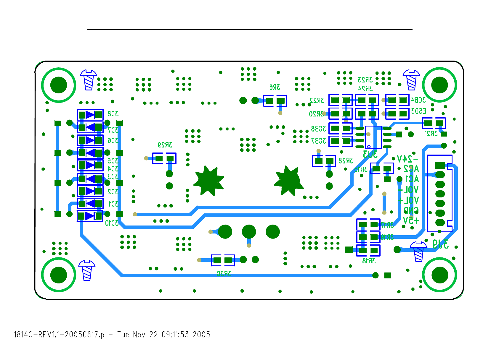
39
HS100 Integrated Hom e Theater System harman/kardon
Page 40

40
HS100 Integrated Hom e Theater System harman/kardon
Page 41

41
HS100 Integrated Hom e Theater System harman/kardon
Page 42

42
HS100 Integrated Hom e Theater System harman/kardon
Page 43

43
HS100 Integrated Hom e Theater System harman/kardon
Pinouts for HS 100
8050, NPN Transistor, SMD 8550, NPN Transistor, SMD
9014, NPN Transistor, SMD DTC343TK, NPN Transistor, SMD
DTC114EKA, PNP Transistor, SMD 2SK3018, Silicon N-channel MOSFET, SMD
AT27C020-70JC, Servo Memory, SMD PT28C020P-90, Servo Memory, SMD
Page 44

44
HS100 Integrated Hom e Theater System harman/kardon
LM833M, pre-amp, SMD NJM4558, pre-amp, SMD
74HCT14, Hex inverting Schmitt trigger, SMD AN8785SB, motor driver, SMD
AM29LV160DB-90EC, flash, SMD MBM29LV160BE-70P, flash, SMD
Page 45

45
HS100 Integrated Hom e Theater System harman/kardon
AML3390DTS, decoder, SMD
208
207
206
205
204
203
202
201
200
199
198
197
196
195
194
193
192
191
190
189
188
187
186
185
184
183
182
181
180
179
178
177
176
175
174
173
172
170
171
169
168
167
166
165
164
163
162
161
160
159
158
157
DA2
DA1
1
VSS_18
2
VD7
3
VD6
4
VD5
5
VD4
6
VD3
7
VD2
8
VD1
9
VD0
10
AOCLK
11
ADATA3
12
ADATA2
13
ADATA1
14
ADATA0
15
ALRCLK
16
AMCLK
17
VSS_18
18
VDD_18
19
VDD_DAC0
20
VSS_DAC0
21
AVID2
22
AVDD_DAC0_B
23
AVSS_DAC0_B
24
AVID1
25
AVDD_DAC0_G
26
AVSS_DAC0_G
27
AVID0
28
AVDD_DAC0_R
29
AVSS_DAC0_R
30
COMP0
31
RSET0
32
VREF0_OUT
33
VRET0_IN
34
AVSS_DAC0
35
AVDD_DAC0
36
AVDD_DAC1
37
AVSS_DAC1
38
VRET1_IN
39
VREF1_OUT
40
RSET1
41
COMP1
42
AVSS_DAC1_R
43
AVDD_DAC1_R
44
AVID3
45
AVSS_DAC1_G
46
AVDD_DAC1_G
47
AVID4
48
AVSS_DAC1_B
49
AVDD_DAC1_B
50
AVID5
51
VSS_DAC1
52
VDD_DAC1
VDD_18
DA0
DD15
DD14
DD13
DD12
DD11
DD10
DD9
DD8
DD7
DD6
DD5
DD4
DD3
DD2
VDD_33
DD1
DD0
VSS_33
VDD_18
AICLK_XIN
AICLK_XOUT
VSS_18
SCLK_XIN
SCLK_XOUT
DMACK_n
DIOW_n/err
DIOR_n/sos
DIORDY/stb
CS0_n/req
CS1_n
DMARQ/dack
CSEL
IRQ14
AML3390DTS
TDO
RESET_n
TEST_n
TCK
TRST_n
DVDD_PLL2
VSS_PLL2
VSS_PLL1
AVDD_PLL2
DVDD_PLL1
AVSS_PLL0
DVSS_PLL0
AVDD_PLL1
DVDD_PLL0
AVDD_PLL0
VDD_33
VSS_33
M2_D15
M2_D1
M2_D2
M2_D3
M2_D4
VDD_18
VSS_18
M2_D5
M2_D6
M2_D0
M2_D7
M2_A0
M2_ECS_n
M2_A1
M2_A10
VDD_33
VSS_33
M2_A2
M2_EOE_n
M2_A3
M2_A11
M2_A4
M2_A9
M2_A5
M2_A8
M2_A6
VDD_18
VSS_18
M2_D9
M2_A7
M2_D10
VDD_33
VSS_33
M2_D13
M2_WE_n
M2_D14
M2_D12
M2_D11
M2_D8
M2_DQM0
M2_CAS_n
M2_RAS_n
M2_SCS_n
M2_BA0
M2_BA1
M2_DQM1
M2_CLKO
VDD_18
TMS
TDI
156
155
154
153
152
151
150
149
148
147
146
145
144
143
142
141
140
139
138
137
136
135
134
133
132
131
130
129
128
127
126
125
124
123
122
121
120
119
118
117
116
115
114
113
112
111
110
109
108
107
106
105
M1_D5
VSS_33
62
61
M1_D7
M1_D6
VDD_33
64
63
VDD_18
VSS_18
M1_DQM0
M1_D15
M1_D14
66
65
67
686970717273747576
M1_D13
M1_D12
M1_D11
M1_D10
M1_D9
M1_D8
M1_DQM1
M1_CLKO
78
77
VSS_18
M1_A11
VDD_18
79
80
M1_A9
M1_A8
M1_A7
M1_A6
8182838485
M1_A5
53
ADC
54
IEC958
M1_D0
55
M1_D2
M1_D1
585756
M1_D4
M1_D3
60
59
AT24C64, EEPROM, SMD
M1_WE_n
M1_CAS_n
M1_RAS_n
M1_SCS_n
MA_BA0
M1_BA1
93
M1_A4
VDD_33
VSS_33
8889909192949596979899
87
86
M1_A10
M1_A0
M1_A1
M1_A2
M1_A3
100
M1_ECS_n
M1_EOE_n
VDD_33
VSS_33
101
103
102
VSS_18
104
Page 46

46
HS100 Integrated Hom e Theater System harman/kardon
78L05, Voltage Regulator, TO-92 78L12, Voltage Regulator, TO-92
79L05, Voltage Regulator, TO-92 MCR100-6, Silicon controlled rectifiers, TO-92
2N5551, NPN, TO-92 8550, PNP, TO-92
8050, NPN, TO-92 9014, NPN, TO-92
PC817, Photoelectric Coupler, DIP KA431, Precision Adjustable Voltage Regulator, TO-92
Page 47

47
HS100 Integrated Hom e Theater System harman/kardon
MN103S47JRB, servo, SMD
O18EZ01, Voltage Regulator, SMD WM8728, Audio DAC, SMD
GNDVIN
DPAK
TOP VIEW
VOUT
T0-252
135
SHARP 018EZ01
Page 48

48
HS100 Integrated Hom e Theater System harman/kardon
BH7862FS, Video Buffer, SMD
LC75710NE, VFD driver, SMD 74HC164, SMD
8-bit serial-in/ parallel-out shift register
Page 49

49
HS100 Integrated Hom e Theater System harman/kardon
LM9022, SMD PIC16C56A, MCU, DIP
Vacuum Fluorescent Display Filament Driver
L7809, Voltage Regulator, TO-220 LM7805, Voltage Regulator, TO-220
BA033T, Voltage Regulator, TO-220
L7812 or LM7812, Voltage Regulator, TO-220 L7912 or LM7912, Voltage Regulator, TO-220
Page 50

50
HS100 Integrated Hom e Theater System harman/kardon
KA5L0380R, Power Switch, In-line Package BU1924, RDS decoder, SMD
1
OUAL
2
RDATA
3
VERL
4
MUX
5
VDD1
6
VSS1
7
VSS3
8 9
CAP T2
RCLK
NC
X0
X1
VDD2
VSS2
T1
BU1924F
HY57V641620HG, SDRAM, SMD DDX2100, Power Device, SMD
1
GNDS
2
OUTNR1
3
OUTNR2
4
VCC2N
5
PGND2N
6
PGND2P
7
VCC2P
8
OUTPR1
9
OUTPR2
10
OUTNL1
11
OUTNL2
12
VCC1N
13
PGND1N
14
PGND1P
15
VCC1P
16
OUTPL1
17
OUTPL2
18 19
NC GNDREF
VSIG2
VSIG1
VREG22
VREG21
INRB
INRA
INLB
INLA
TWARN
FAULT
TRI-STATE
PWRDN
CONFIG
VL
VREG12
VREG11
GNDR1
16
15
14
13
12
11
10
36
35
34
33
32
31
30
29
28
27
26
25
24
23
22
21
20
DDX2100
LM4880, Audio Power Amplifier, SMD CD4052, Analog Multiplexer, SMD
Page 51

51
HS100 Integrated Hom e Theater System harman/kardon
DDX8001, Digital Audio Processor, SMD
AAT3522IGY-3.08, Microprocessor Reset Circuit, SMD RT9161/A-33, Voltage Regulator, SMD
74HC158, data selectors, SMD CS5333, A/D Converter, SMD
Page 52

52
HS100 Integrated Hom e Theater System harman/kardon
KBU8M, Bridge Rectifiers, In-line Package FCH20A20, Schottky diode, In-line Package
FQA11N90, MOS-FET, In-line Package FAN7554, Versatile PWM Controller, DIP
Page 53

53
HS100 Integrated Hom e Theater System harman/kardon
87654321
IC5 7805
Vin
2
C7
104/25V
EC21
Vout
GND
1000U/35V
1
D10
IC3 7812
Vin
IC4 7912
Vin2GND1Vout
A +5V / 200mA (600mA Max)
3
220u/10V
220uF/16V
R39
300R
1N4148
R36 1K
R34
1K/2W
A+12V / 100mA
3
Vout
GND
EC23
2
100u/16V
EC24
100u/16V
3
A-12V / 100mA
C6
EC9
104/25V
L5
20uH
EC11
EC12
220uF/16V
+5.0V / 900 mA
IC6
BA033T
1
Vin
Vout
GND
2
R18
C9
R19
2.2K
100uF/16V
R38
LF3
1
1
1K/2W
470UH
Title
Number RevisionSize
A3
Date: 29-Aug-2005 Sheet of
File: F:\HS100.ddb Drawn By:
C4
104/25V
C5
104/25V
+3.3V / 340mA
3
EC15
220u/10V
2.2K
C16
104/50V
HS100 PWOER SUPPLY
CN6
5
+12V
4
GND
3
-12V
2
+5V
GND
REV 1.9
D
C
B
A
1
CON5-2.5A
CN3
10
+12V
9
GND
8
-12V
7
GND
6
+3V3
5
A+5V
4
D+5V
3
GND
2
S+5V
1
GND
CON10-2.5A
CN4
1
+5V
2
STBY
3
GND
CON3-2.5
CN5
+22V
GND
Yicong Huang
TR1
8
,9
R4
R5 10R
C8
473/25V
C2
AGND
8
FAN7554
413
2
AGND
AGND
R23
10R
IC2
1U/50V
4.7uF/160V
D13
FR107
567
EC22
EC2
AGND
R1
68K/1W
D1
FR107
2N5551
471/400V
C13
470pF
Q3
PH1 PC817
CY4
D16 IN4148
R7
30K 1/4W
AGND
IC7
KA431
100K 1W(NC)
R26 20R 1/4W
R27 1K
C1
103/1KV
R8
30K 1/4W
ZD1
24V
R9
30K
R10
10K
R37
1
R25 10R D15 FR107
DS
G
R35
1K 1/4W
AGND
D2 FR107
D3 FR107
104/25V
R24
68K 1W
Q6
FQP11N90
R28
0.22/2W
FR207
C3
D14
R12 5.1KR11 5.1K
C10
103/1kV
C14 473/25V
AGND
AGND
AGND
6
3
4
2
1,
R13 220R
R14 220R
R6 4.7M
CY5 471/400V
6
TR2
,7
5
4
2
1
CY6 471/400V
PH2 PC817
IC8
KA431
12,13,
CY3
471/400V
D
Drain2VCC
3
FB1
10uH
R21
100K
4
R20
2.2K
Q1 2N5551
R3
10R
EC1
47UF/50V
C11
104/25V
AGND
Q7
9014
AGND
AGND
ZD2
18V
EC16
220u/400v
47U/50V
R22
12K
AGND
EC17
47K
473/25V
C12
272/25V
IC1 5L0380
GND1FB
R2
470k 1/4W
AGND
C
+
+
~1
B
CY1
221/400V
NTC
I&T
5D-9
A
CN1
To Swicth
~2
~
DB1
~
8A/800V
-
-
AGND
CX2
104/275V
LF2
UF1601
CY2
221/400V
CX1
104/275V
LF1
LCL-203A
R0
1M
RV1
10D471K
FU1
FUSE_MARK_T
T3.15AL/250V
CN2
AC Input
CX3
104/275V
1 2 3 4 5 6 7 8
FR107
D5
11
10,
12
D6 FR107
13
D7 21DQ10
16
17
18
D8 RF107
14
D9
31DQ06
15
D11 1N4148
D12 1N4148
D17 20A/200V
1
10
8,9,
3
1
3
D18 20A/200V
14
R31 1K R32 5.1K
R15
5.1K
EC25
1UF/50V
EC3
100u/25V
EC5
100u/25V
EC7
220u/16V
EC13
1000u/16V
C8550
2
EC18
2
1000U/35V
R29 2.2K
R30 330R
MCR100-6
Q5
L2
L3 20uH
L4
SC1
R16
100R
L6
EC19
20uH
20uH
10uH
R17
1000U/35V
R33 5.1K
5K1
L7 20UH
EC4
EC6
EC8
220u/16V
Q4
9014
EC10 2.2uF/25V
EC14
1000u/16V
EC20
100u/25V
100u/25V
1
1000U/35V
Page 54

5
54
4
3
2
1
HS100 Integrated Hom e Theater System harman/kardon
A4
AMCLK
ASCLK
ALRCLK
D D
A0
NRST#
SDD[0..15]
SDA[0..2]
SDMARQ
DMACK
SDIOWR#
SDIORD#
SCS1FX#
C C
SCS3FX#
SINTRQ
12
VD4
SDD[0..15]
SDA[0..2]
SDMARQ/dack
SDMACK_n
SDIOW_n/err
SDIOR_n/sos
SCS0_n/req
SCS1_n
SIRQ14
<2>:SERVO
B B
ADATA3
HW_MUTE
PHONE_DET
DI/SDA
CL/SCL
ML
RESET_n
REMOTE
V_COMP
V_Y
V_C
B/Cb/Pb
R/Cr/Pr
G/Y/Y
V_SW1
TVFORMAT0
TVFORMAT1
RGB_SWITCH
ADC_DAT
TDI
AIN_SEL0
AIN_SEL1
SW2
DO
DI/SDA
CL/SCL
TUNER_CE
TUNER_ON
RDATA
RCLK
A4_2
<4>:AUDIOOUT
AMCLK
ASCLK
ALRCK
ADATA3
HW_MUTE
PHONE_DET
DI/SDA
CL/SCL
ML
RESET_n
A3_1
<3>:VIDEOOUT
REMOTE
V_COMP
V_Y
V_C
B/CB/PB
R/CR/PR
G/Y/Y
V_SW1
TVFORMAT0
TVFORMAT1
RGB_SWITCH
A5_2
<5>:INPUT
RESET_n
AMCLK
ASCLK
ALRCLK
ADC_DAT
TDI
AIN_SEL0
AIN_SEL1
SW2
DO
DI/SDA
CL_SCL
TUNER_CE
TUNER_ON
RDATA
RCLK
SCART_R
SCART_L
SCART_L
SCART_R
TVIN_R
TVIN_L
TVIN_L
TVIN_R
4
<1>:MPEG
Harman Kardon, Northridge, California 91329, USA
Title
HS100 MAIN BOARD 050725
Size Document Number Rev
1239C-PV1 3.43
A4
3
Date: Sheet
2
224Tuesday, November 22, 2005
of
1
A A
5
Page 55

5
55
4
3
2
HS100 Integrated Hom e Theater System harman/kardon
1
220U/16V
FB5 FB
L12 FB
L20 FB
L11 FB
EC4
+
220U/16V
L22 FB
L7 FB
C3
+
DGND
CB10
104
A3V_S
TO SERVO
VL
TO CS5333
VPP
TO U7
CB116
104
VA5V
TO BH7862
TO SERVO
S5VA
5V
TO 74HC4052
U3
123
GND
VIN
VOUT
79L05
47UF/16V
-5V
D5VCC
CB9
C6
+
104
DGND
D5VCC
PAD1
INSTALL1
GND
123456789
GND
GND
GND
+
GND
FB3 FB
L21 FB
C16
220U/16V
D24
IN5393
GND
GND
GND
GND
+5V
5VD
D26
IN5393
PAD2
INSTALL1
GND
GND
GND
GND
GND
123456789
TO U5
GND
GND
GND
FOR LM833&NJM4558
+12VCC
EC10
+
CB7
GND
AAGND
GND
-12VCC
U2 SHARP 018EZ01
GND
GND
GND
GND
104
CB13
104
135
GND
GND
GND
47UF/25V
PAD3
INSTALL1
D27
IN5393
GND
123456789
GNDVIN
DPAK
TOP VIEW
T0-252
CB8
104
CB14
104
+A12V
-12VA
VOUT
C14
+
47U/16V
+
EC12
47U/16V
TP6
+1.8V
C5
470U/16V
+
VCORE
C17
100U/16V
CB122
104
VCC1.8
FB6 50R
+
EC6
D D
CON7
TOPVIEW
+12V
GND
-12VA
GND
+3.3V
D5V
A5V
POWER SUPPLY
GND
S5VCC
SGND
C C
DGND
B B
220U/16V
FB1 50R
1
2
FB4 50R
3
4
5
FB9 50R
6
7
8
FB7 50R
9
10
SGND AGND
220UF/16V
PGND
C13
470U/16V
C18
470U/16V
C1
+
CB91
104
PGND
CB5 104
CB11 104
FB2 50R
S5V
VCC3.3
VA+5V
C11
470U/16V
-12VA
+12VCC
-12VCC
CB2
104
R75 75R
CB93
104
A A
Harman Kardon, Northridge, California 91329, USA
Title
HS100 MAIN BOARD 050725
Size Document Number Rev
1239C-PV1
A3
5
4
3
2
Date: Sheet
1
of
324Tuesday, November 22, 2005
3.43
Page 56

56
HS100 Integrated Home Theater System harman/kardon
5
Core_1.8
TUNER_CE
M1_WE_n
M1_DQM1
M1_DQM0
M1_CLKO
M1_BA0
M1_BA1
M1_CAS_n
M1_RAS_n
67
M1_DQM1
M1_DQM0
M1_ECS_n
Audio
ADATA0
ADATA1
ADATA2
93
MA_BA0
M1_CLKO
ADATA3
8990919492
M1_BA1
M1_WE_n
Memory #2
AOCLK
ALRCLK
15
16
TDI
TMS
TCK
TDO
M1_SCS_n
M1_CAS_n
M1_RAS_n
M1_SCS_n
IEC958
AMCLK
54
M1_A10
M1_A11
M1_A9
78
M1_A10
M1_A11
Memory #1
ADC
Core_3.3
M1_A8
M1_A9
M1_A7
M1_A8
DGND
DGND
VCC3.3
ADATA0
ADATA1
ADATA2
ADATA3
TUNERON/OFF
1007677
101
M1_EOE_n
143
M2_D0
151
M2_D1
150
M2_D2
149
M2_D3
148
M2_D4
145
M2_D5
144
M2_D6
142
M2_D7
114
M2_D8
124
M2_D9
122
M2_D10
115
M2_D11
116
M2_D12
119
M2_D13
117
M2_D14
152
M2_D15
141
M2_A0
139
M2_A1
135
M2_A2
133
M2_A3
131
M2_A4
129
M2_A5
127
M2_A6
123
M2_A7
128
M2_A8
130
M2_A9
138
M2_A10
132
M2_A11
110
M2_SCS_n
111
M2_RAS_n
112
M2_CAS_n
118
M2_WE_n
108
M2_BA1
109
M2_BA0
107
M2_DQM1
113
M2_DQM0
140
M2_ECS_n
134
M2_EOE_n
106
M2_CLKO
1413121110
D5VCC
R19
R20
2.7K
2.7K
CB18
CB19
CB17
104
Core_1.8
+
EC2
CB28
100U/16V
D D
C C
B B
A A
104
M2_D[0..7]
M2_A18
M2_A19
M2_A20
DAC_ML
M2_A[0..11]
M2_RAS_n
M2_CAS_n
M2_WE_n
M2_DQM1
M2_DQM0
M2_EOE_n
Power_on
Configeration
ADATA0
ADATA1
ADATA2
ADATA3
ASCLK
ALRCK
AMCLK
ADC_DAT
RESET_n
HW_MUTE
M2_BA1
M2_BA0
TDI
TWARN
PWRDN
DEBUG PORT
104
CB29
104
R35
10k
104
CB30
104
M2_D[0..7]
VFDCLK
M2_A[0..11]
R38
R36
10k
10k
CB20
104
CB31
104
VCC3.3
R34
10k
CON2
+3.3V
GND
TMS
TDI
TCK
TDO
ARC JTAG
5
DGND
DGND
R17
2.7K
M2_A18
M2_A19
M2_A20
RESET_n
1
2
3
4
5
6
M2_D0
M2_D1
M2_D2
M2_D3
M2_D4
M2_D5
M2_D6
M2_D7
M2_A0
M2_A1
M2_A2
M2_A3
M2_A4
M2_A5
M2_A6
M2_A7
M2_A8
M2_A9
M2_A10
M2_A11
R18
2.7K
4
VCC1.8
M1_A7
M1_A6
M1_A5
M1_A6
M1_A4
M1_A5
M1_A4
M1_A3
M1_A2
M1_A3
M1_A1
M1_A2
M1_A0
M1_A1
M1_A[0..11]
M1_D15
M1_A0
M1_D14
M1_D14
M1_D15
M1_D12
M1_D13
M1_D13
M1_D11
M1_D11
M1_D12
M1_D9
M1_D10
M1_D10
M1_D8
M1_D9
M1_D7
M1_D8
M1_D6
M1_D7
M1_D6
M1_D5
M1_D5
M1_D4
M1_D3
M1_D4
M1_D2
M1_D3
M1_D1
M1_D2
M1_D0
555657585960636475747372717069689697989988858483828195
M1_D1
M1_D[0..15]
M1_D0
AML3370
U4
CLOCKS
MPEG AUDIO VIDEO
R28
100K
SCLK_XOUT
182
AICLK_XOUT
SCLK_XIN
185
18453181
22PF
C23
AICLK_XIN
CB46
104
PLL PLL PLL
AVDD_PLL0
AVSS_PLL0
DVDD_PLL0
AVDD_PLL1
DVSS_PLL0
157
158
160
161
159
DGND
AV1 AV0
VCC1.8Q
CB47
104
AVGND
162
R21 1 0K
R22 1 0K
TDI
TMS
155
156
167
R25
open(OPT)
TCK
171
TEST
TDO
DGND
RESET_n
TEST_n
TRST_n
170
169
168
AV0
R16
10K
Y1
27M
C22
22PF
DGND DGND
4
L1
FB
Core_1.8
80
VDD_18
VDD_18
DVDD_PLL1
VSS_PLL1
163
CB48
104
126
1056618
VDD_18
VDD_18
VDD_18
VSS_PLL2
AVDD_PLL2
165
164
147
186
VDD_18
VDD_18
DVDD_PLL2
166
FB
L8
220U/16V
208
VDD_18
AV1
EC7
1176579104
VSS_18
VSS_18
VSS_18
Core_1.8
+
DGNDDGND
125
146
VSS_18
VSS_18
VSS_18
Power
IRQ14
172
173
CSEL
SIRQ14
3
VCC3.3
DGND
1836287
VSS_18
VSS_18
CS0_n/req
CS1_n
CSEL
176
175
SCS0
SCS1
3
Core_3.3
VDD_33
DMARQ/dack
DMACK_n
180
174
179
SDMACK
SDMARQ/dack
L2
FB
121
103
VDD_33
VDD_33
3.3VCore 1.8V Core GND
DIOW_n/err
DIORDY/stb
177
178
SDIOR
SDIOWR
137
1548661
VDD_33
VDD_33
DIOR_n/sos
207
SDA2
Core_3.3
+
EC1
100U/16V
CB21
104
153
136
120
190
102
VSS_33
VSS_33
VDD_33
VDD_33
VSS_33
VSS_33
VSS_33
GND
IDE / DVD_DSP
DD12
DD13
DD14
DD15
DA0
DA1
DA2
200
201
202
203
204
205
206
SDD12
SDD15
SDD14
SDD13
SDD11
SDA0
SDA1
SDA[0..2]
C20
47PF
CB22
104
CB24
104
CB23
104
DGND
189
VSS_33
VSS_33
GPIO,Video
1.8V
1.8V
GND
GND
3.3V
AVDD_DAC0_G
AVDD_DAC0_R
GND
1.8V
GND
3.3V
AVDD_DAC1_G
AVDD_DAC1_R
GND
DD6
DD7
DD8
DD9
DD10
DD11
194
195
196
197
198
199
SDD10
SDD6
SDD7
SDD8
SDD9
SDD5
DGND DGND
CB26
104
CB25
104
gpio7
gpio6
gpio5
gpio4
gpio3
gpio2
gpio1
gpio0
VDD_DAC0
VSS_DAC0
AVDD_DAC0
AVDD_DAC0_B
AVSS_DAC0
AVSS_DAC0_B
AVSS_DAC0_G
AVSS_DAC0_R
COMP0
RSET0
VREF0_OUT
VRET0_IN
AVID0
AVID1
AVID2
AVID3
AVID4
AVID5
COMP1
RSET1
VREF1_OUT
VRET1_IN
VDD_DAC1
VSS_DAC1
AVDD_DAC1
AVDD_DAC1_B
AVSS_DAC1
AVSS_DAC1_B
AVSS_DAC1_G
AVSS_DAC1_R
DD1
DD2
DD3
DD4
DD5
188
191
192
193
SDD3
SDD1
SDD2
SDD4
C21
10PF
CB27
104
VD7
VD6
VD5
VD4
VD3
VD2
VD1
VD0
187
SDD0
2
D5VCC
CB62
104
DGND
VD7
2
VD6
3
VD5
4
5
VD4
6
7
VD1
8
9
19
20
35
22
25
28
34
23
26
29
CB37
30
104
31
32
33
27
24
21
44
47
50
41
40
39
38
52
51
36
49
46
43
37
48
45
42
DD0
D5VCC
AR2
4.7K
R11 187
CB39
104
DGND
DGND DGND
CB42
104
CB38 104
R12
187
CB43
104
R23
10K
2
U15
1
8
NC
VCC
DI/SDA
CL/SCL
REMOTE
CB33
104
CB40 104
VCC3.3Q1
CB45
CB44
104
104
Q0 R ES ERVE
Q1-Q3 FS0,FS1 AND RGB_SEL FOR SCART OUT
Q4,Q5 Audio INPUT (AUX,SCART,TUNER)SELECT
Q6 OPTICAL/OAXIAL INPUT SELET
Q7 SCART OUT Y/VBS AND R/C SELECT
SDD[0..15]
R24
10K
5
SDA
6
SCL
4
GND
24C64
VD4
RDSCLK
RCLK
VCC3.3Q0
CB34
104
AVID0
AVID1
CB35
104
NC
NC
WP
CB32
104
L6FB
CSEL
DI/SDA
CB36
104
2
3
7
VCC3.3
VDD_DAC0
+
VDD_DAC1
EC3
220U/16V
CB41
104
DGND
D5V
R27 10 k
AMUTE
PRE_RE
REMOTE
VFD_CE
DI/SDA
CL/SCL
MCU-CLK
DO
CL/SCL
DI/SDA
VD4
VFD_CE
VCC1.8
L3FB
VCC3.3
L4
FB
R9
75R
V_Y
V_C
V_COMP
B/Cb/Pb
G/Y/Y
R/Cr/Pr
+
EC5
220U/16V
DGND
1
A
VCC
2
B
3
Q0
4
Q1
5
Q2
6
Q3
MR
7 8
GND CP
DGND
U5
74VHC164
Harman Kardon, Northri dge, California 91329, USA
Title
HS100 MAIN BOARD 050725
Size Document Number Rev
1239C-PV1
C
Tuesday, November 22, 2005
Date: Sheet
Q7
Q6
Q5
Q4
R2 10k
VCC1.8
L5FB
R3 10k
RR1 10 k
RR2 10 k
14
13
12
11
10
9
AMUTE
FB26 FB
FB32 FB
FB31 FB
FB33 FB
FB34 FB
CON1
16
15
14
13
12
11
10
+5V
AIN_SEL1
AIN_SEL0
1
NA
NA
9
8
7
6
5
4
3
2
1
DAMP CON/16P,1.0mm
CB108
104
SDD[0..15]
SDA[0..2]
SDIOR
SDIOWR
DETECT
SDMARQ
SDMACK
SCS0
SCS1
CSEL
SIRQ14
1
D5V
NA
NA
NA
AMUTE
TWARN
PWRDN
ADATA2
ADATA1
ADATA0
ALRCK
ASCLK
AMCLK
DATA/SDA
CLOCK/SCL
RESET_n
SW2
AIN_SEL1
AIN_SEL0
RGB_SWITCH
TVFORMAT1
TVFORMAT0
4
C9
9
8
7
6
5
4
3
2
1
PH-10A-2.0mm
C50
C10
TWARN
PWRDN
ADATA2
ADATA1
ADATA0
ALRCK
ASCLK
AMCLK
DI/SDA
CL/SCL
of
3J3
+5V
GND
AMUTE
RESET
IR
VFDCE
SDA
SCL
MCU-CLK
C57
C55
AMUTE
24
3.43
Page 57

5
57
D3.3
DGND
M2_A20
M2_A19
M2_A18
M2_BA1
M2_BA0
M2_CAS_n
M2_RAS_n
M2_DQM1
M2_DQM0
M2_A[0..11]
M2_EOE_n
M1_D[0..15]
M1_A[0..11]
CB50
104
R29
22
M1_SCS_n
M1_RAS_n
M1_CAS_n
M1_WE_n
DGND
M2_BA1
M2_BA0
M2_CAS_n
M2_RAS_n
M2_DQM1
M2_DQM0
M2_A[0..11]
M2_EOE_n
C24
6.8PF
D3.3
R30 22
R31 22
R32 22
R33 22
M1_A0
M1_A1
M1_A2
M1_A3
M1_A4
M1_A5
M1_A6
M1_A7
M1_A8
M1_A9
M1_A10
M1_A11
M2_A11
M2_A10
M2_A9
M2_A8
M2_A7
M2_A6
M2_A5
M2_A4
M2_A3
M2_A2
M2_A1
M2_A0
M1_D[0..15]
M1_A[0..11]
D D
C C
B B
A A
CB49
104
M1_BA0
M1_BA1
M1_CLKO
M1_SCS_n
M1_RAS_n
M1_CAS_n
M1_WE_n
M1_DQM0
M1_DQM1
5
23
24
25
26
29
30
31
32
33
34
22
35
20
21
38
37
19
18
17
16
15
39
U6
1MX16X4
A0
A1
A2
A3
A4
A5
A6
A7
A8
A9
A10
A11
BA0
BA1
CLK
CKE
CS#
RAS#
CAS#
WE#
DQML
DQMH
4
3
2
1
HS100 Integrated Home Theater System harman/kardon
M1_D0
2
DQ0
4
M1_D1
DQ1
M1_D2
5
DQ2
7
M1_D3
DQ3
M1_D4
8
DQ4
M1_D5
10
DQ5
11
M1_D6
DQ6
M1_D7
13
DQ7
42
M1_D8
DQ8
M1_D9
44
DQ9
M1_D10
45
DQ10
47
NC
NC
VDD
VDD
VDD
VSS
VSS
VSS
RESET_n
48
50
51
53
36
40
1
14
27
3
9
43
49
28
41
54
6
12
46
52
R122
4.7K
M1_D11
M1_D12
M1_D13
M1_D14
M1_D15
D3.3
CB54
CB52
CB53
104
104
104
D3.3
DGND
CB55
104
DGND DGND DGND
DGND
M2_A20
M2_A19
M2_A18
RESET_n
D3.3
CB56
104
CB58
104
DGND
VPP
3
CB57
104
U7
37
9
16
17
48
1
2
3
4
5
6
7
8
18
19
20
21
22
23
24
25
45
15
12 11
GND
VCC
GND
A19
BYTE
A18
A17
A16
A15
A14NCNC
A13
DQ14
A12
A11
DQ13
A10
DQ12
A9
DQ11
A8
DQ10
A7
DQ9
A6
DQ8
A5
DQ7
A4
DQ6
A3
DQ5
DQ4
A2
A1
DQ3
DQ2
A0
DQ1
DQ15/A-1
DQ0
RY/BY
RESET
AMD29LV160DB-90
MBM29LV160BE-70
27
46
47
10
NC
13
14
43
41
39
36
34
32
30
44
42
40
38
35
33
31
29
26
CE
28
OE
WE
DGND
DQ11
DQ12
DQ13
DQ14
DQ15
VDDQ
VDDQ
VDDQ
VDDQ
VSSQ
VSSQ
VSSQ
VSSQ
VPP
R121
R123
4.7K
4.7K
RESET_n
RESET_n
4
CE#
DGND
M2_D7
M2_D6
M2_D5
M2_D4
M2_D3
M2_D2
M2_D1
M2_D0
D3.3
EC8
220UF/16V
M2_WE_n
+
DGND
+
DGND
M2_D[0..7]
M2_WE_n
FB27 FB
C19
220U/16V
VCC3.3
CB51
104
DGND
2
VCC3.3
CB16
104
+
C8
220UF/16V
M2_D[0..7]
Harman Kardon, Northridge, California 91329, USA
Title
HS100 MAIN BOARD 050725
Size D ocument Number Re v
1239C-PV1 3.43
B
Date: Sheet
524Tuesday, November 22, 2005
1
of
Page 58

TRVSW
58
SPIN
TRVIN
STANDBY
FOIN
TRIN
DMV
VHALF
TRAY
OPSW
CLSW
R127 33K
C72
560P
D_GND
R119 1 5K
R128 6.2K
Q26
8550
HS100 Integrated Home Theater System harman/kardon
C26
560P
D_GND
R130
10K
D1.5VDVCC
321
R124 18K
R131 7.5K
C74 200P
C59 200P
R1347.5K
R13510K
CB77
104
C129
NA
P_GND
P_GND
D_GND
CB66
104
12345
GND
CLSW
CN4
5X2.0mm
LM+
OPSW
LM-
AN8785SB
2
IN5
3
OPOUT
4
OPIN-
5
OPIN+
6
VREF
7
IN2+
30 29
FIN1 FIN2
8
CH.4SW
9 20
IN2- IN3
10 19
PVcc2 PVcc3
11
D2+
12
D2-
13
D3+
14
D3-
P_GND
U1
281
D1+D1-
27
PGND1
26
D5-
25
D5+
24
PVcc1
23
IN1
22
SVcc
21
IN4
18
D4-
17
D4+
16
Standby
15
PGND2
CB69
104
C77
220uF/16V
S5V
CB131
104
R126
7.5K
R133
5.6K
D3.3V
R129 100K
1
SPDM-
2
SPDM+
3
LIMITSW
4
LIMITSW
5
SLEDMT-
6
D_GND
SLEDMT+
CN5
6X2.0mm
S3V3
VA+5V
L30 FBR141 18K
L28 FB
L29 FB
D3.3V D3V_SA3.3V A3V_S
DVCC
FF+
TT+
RFP
FE2
FE1
VREF2.2V
PINDVD
PINCD
R203
D_GND
CB79
104
CB95
104
27K
2
R201
18K
R204
1.2K
EC41
47UF/10V
CB80
104
C25
+
100UF/25V
CDDVD
F2
TB
F1
TC
RFP
TD
TA
T1
T2
S5VA
L13 FB
PINDVD
PINCD
3
Q25
8050
1
VRCD
VRDVD
CLD
DLD
R202
22
EC40
100uF/16V
HFM
S5VA
S5VA
Q5
9014
R153
10K
321
R154
10K
321
321
Q7
9014
Harman Kardon, Northridge, California 91329, USA
Title
HS100 MAIN BOARD 050725
Size Document Number R ev
A3
Date: Sheet
1239C-PV1 3.43
A_GND
Q6
9014
R155
10K
R158
10K
R151
3
Q3
2
9014
R159
1
10K
10K
10K
R152
CDDVD
3
Q4
2
9014
1
VRDVD
VRCD
of
624Tuesday, November 22, 2005
L10 FB
C79
HFM33V
47uF/6.3V
R149 56R
R147
2R2
R172 1 0K
1
2
3
A3.3V
R167
10K
3
2
1
+
LPCO1
LPCO2
CD/DVD
F-
1
F-
2
F+
3
T+
4
T-
5
C
6
D
7
CDDVD-SW
8
RF
9
A
10
B
11
F
12
GND-PD
13
VC
14
VCC
15
E
16
NC
17
VR-CD
18
VR-DVD
19
CD-LD
20
MD
21
HFM
22
NC
23
LD-DVD
24
GND-LD
CN3
FH12-24S-0.5SH
FOR SANYO DV34
VC
RFVCC
E
HFM
F+
T+
TC
D
A
B
F
A_GND
R145
27R
Q8
9014
Q1
8550
C80
47uF/6.3V
R150 56R
2
A_GND
R148
2R2
R146
27R
C101
10uF/16V
1
2
Q2
8550
3
EC11
220U/16V
+
R170 10K
3
Q13
9014
1
NA
2
10K
A_GND
S5VA
A_GND
10K
CB87
104
S5VA
1
3
CB86
104
CLD
DLD
Q22
DTA114TCA
OR
DTA114EKA
L9 FB
Page 59

59
HS100 Integrated Hom e Theater System harman/kardon
U8
FADR0
RESET_n
12
11
FADR1
10
FADR2
FADR3
1 2
L24 FB
EC43
4.7uF/25V
1
3 4
5 6
L15 FB
+
A_GND
FADR4
FADR5
FADR6
FADR7
27
FADR8
26
FADR9
23
FADR10
RN2
4X47K
25
FADR11
FADR12
28
FADR13
7 8
29
FADR14
FADR15
FADR16
30
FADR17
22
/CE
24
/OE
D_GND
A3.3V
D16 1N4148
1 2
CB4 10 4
S5VA
R193
R211
470R
470R
32
32
Q23
8050
1
R212
R213
470R
470R
Harman Kardon, Northridge, California 91329, USA
Title
Size Document Number Re v
C
Date: Sheet
DVCC
HIORDY
R205 10K
IOCS16
R206 10K
R207 10K
/DMACK
R208 10K
R175 10K
SDD[0..15]
DVCC
SDMARQ
SDMACK
R207 10 K
/DMACK
/IORD
SDIOWR
R118 10 K
R144 4.7K
/HRST
VD4
R142 0R
NA
R8 10R
NA NA
SDIOWR
SDIOR
SIRQ14
SDA1
SDA0
SDA2
SCS0
SCS1
R125 10 K
D_GND
CLSW
OPSW
HFM33V
D3.3V
R156 10K
/DASP
VD4
C108
104
SDD9
SDD6
SDD8
SDD7
SDD11
SDD4
SDD10
SDD5
SDD13
SDD2
SDD12
SDD3
SDD15
SDD0
SDD14
SDD1
HIORDY
IOCS16
SDMARQ
D_GNDD3V_S
CLSW
OPSW
HFM33V
RN18 33X4
RN17 33X4
RN16 33X4
RN13 33X4
R182 82R
R183 82R
R184 33R
R185 33R
R186 33R
R187 82R
RN12 82X4
R189 33R
R190 33R
R215 10 K
R157 10K
R160 0R
1
C151
10PF
D_GND
78
56
34
12
78
56
34
12
78
56
34
12
78
56
34
12
78
56
34
12
/DMARQ
/DMACK
D_GND
R140 10R
R143 0R
32
Q20
8050
HDD9
HDD6
HDD8
HDD7
HDD11
HDD4
HDD10
HDD5
HDD13
HDD2
HDD12
HDD3
HDD15
HDD0
HDD14
HDD1
/IOWR
/IORD
IORDY
INTRQ
/IOCS16
DA1
DA0
DA2
/CS1FX
/CS3FX
NA
D_DRAM
FADR17
FADR11
FADR9
FADR8
FADR13
FADR14
FADR16
FADR15
FADR12
FADR7
FADR6
FADR5
FADR4
FADR3
FADR2
FADR1
FADR0
FDT0
FDT1
FDT2
FDT3
FDT4
FDT5
FDT6
FDT7
FADR10
D3.3V
NRST
R191 1K
R192 1K
NWE
/CE
/OE
D3V_S
CB134 104
EC42
1 2
+
D3V_S
D_GND
10uF/16V
D1.5V
R188 1 0K
C124
10PF
C125
10PF
D_GND
10
11
12
13
14
15
16
17
18
19
20
21
22
23
24
25
26
27
28
29
30
31
32
33
34
35
36
37
38
39
40
41
42
43
44
D_GND
D3V_S
1
2
3
4
5
6
7
8
9
P2/EXINT0
P3/EXINT1
P4/EXCNT0
VDD3
VSS
P5/EXCNT1
P7/FADR17
P8/FADR18
FADR11
FADR9
VDD15
FADR8
FADR13
FADR14
NWE
FADR16
FADR15
DRAMVSS
DRAMVDD15
DRAMVDD33
VSS
FADR12
FADR7
FADR6
FADR5
FADR4
FADR3
FADR2
FADR1
FADR0
VSS
VDD3
FDT0
FDT1
FDT2
FDT3
FDT4
FDT5
FDT6
FDT7
NCE
FADR10
NOE
MMOD
HDD9
HDD6
HDD5
HDD8
HDD7
/HRST
CB135
104
167
168
169
170
171
172
173
174
175
176
VSS
VDD3
HDD9
HDD6
HDD8
HDD7
VDDH
NRESET
MASTER
VSS
SCLOCK/Dwire0
SDATA/Dwire1
TxD/Dwire2/MDATA
RxD/Dwire3/MCLOCK
VDD3
NRST
SERIAL_Rx
SERIAL_Tx
454950515253545556575859606162636465666768
464748
CB73 104
OSCI
D_GND
R198
Y2
1M
33.86M
R199
100R
CB82 104
C161 103
HDD5
OSCI1
HDD10
166
HDD4
165
HDD10
OSCO1
HDD11
164
HDD4
VSS
R196 7.5K
TRSDRV
HDD3
163
HDD11
DRV0
R197 5.6K
SPDRV
/CS1FX
148
NCS1FX
NCS3FX
VDD15
VSS
CB74 104
A_GND
INTRQ
/IOCS16
DA1
/IORD
DA0
DA2
143
144
145
146
147
DA0
VSS
DA2
VDD3
AVDDD
PLFIL2
PLFIL1
VREFC
C112 333
CB68 104
C119 33PF
CB63 104
142
NPDIAG
VREFB
CB60 104
DA1
VREFA
141
NIOCS16
AVSSD
140
C114 103
/DMACK
139
INTRQ
VC0
R195 3.9K
138
IORDY
NDMACK
RESI
ANAMONI
137
C115 47PF
/IOWR
/DMARQ
133
134
135
136
VSS
VDD3
NIORD
NIOWR
NTRYCL/MONI7
NEJECT/MONI6
DASPST/MONI5
MASPOL/MONI4
CWBLOUT
POFLT
CDATA
CCAPA
CGD
88
C116 562
104
C122 183
CB64
DMARQ
VDD3
MONI3
MONI2
MONI1
MONI0
AVSSA
DAC0
DAC1
AVDDA
AVDDB
VCOF
CWBLIN
CSLFLT
CTKC
AVSSB
LPCO1
LPCO2
VHALF
VREFH
AVSSC
VIN10
RFINP
RFINN
AVDDC
A3V_S
LPC1
LPC2
D_GND
C157
105
CB75
104
CB72 104
C150 105
R210
15K
CB70
A3V_S
104
R194 1K
L14
FB
C158 103
D_GND
C109
221
D3.3V
R17710K
R20910K
R17610K
R178
10K
D_GND
R180 10K
102
C139
A_GND
C110
152
R181 68K
LPC1
CB132
104
A_GND
VHALF
L25 FB
Q24
8050
CB76
CB81
104
104
D3V_S
CB71 104
132
131
130
129
128
127
VSS
126
125
124
123
122
121
120
119
118
AD0
117
AD1
116
AD2
115
114
RVI
113
112
111
110
109
108
107
106
105
104
103
102
101
100
99
VIN9
98
VIN4
97
VIN3
96
VIN2
95
VIN1
94
VIN8
93
VIN7
92
VIN6
91
VIN5
90
89
VREFH
L26
FB
105
C156
159
VSS
157
158
VDD15
DRAMVSS
DRAMVDD15
HDD15
HDD0
HDD1
HDD13
HDD14
/DASP
/CS3FX
149
150
151
152
153
154
155
156
HDD0
HDD1
VDD3
NDASP
HDD15
HDD14
HDD13
U9
HDD2
HDD12
160
161
162
HDD2
HDD3
HDD12
PV1
DRV1
DRV2
DRV3
DRV4
DRV5
DRV6
DRV7
VSS
DRV8
DRV9
DRV10
VDD3FGTX
69707172737475767778798081828384858687
D1.5V
STANDBY
TRVSW
CD/DVD
TRAY
D_DRAM
D3V_S
D1.5V
IORDY
13
A0
I/O0
14
A1
I/O1
15
A2
I/O2
9
17
A3
I/O3
8
18
A4
I/O4
7
19
A5
I/O5
6
20
A6
I/O6
5
21
A7
I/O7
A8
A9
A10
A11
4
A12
A13
31
A14
VPP
3
32
A15
VCC
2
A16
A17
1
16
A18
GND
CE
OE
AT27C020
PT28C020
VREFH
D3.3V
+
EC44
4.7uF/25V
D_GND
HS100 MAIN BOARD 050725
1239C-PV1
CB59
FDT0
FDT1
FDT2
FDT3
FDT4
FDT5
FDT6
FDT7
NWE
104
STANDBY
TRAY
TRVSW
CD/DVD
SPDRV
TRSDRV
CB1
104
DMV
FOIN
TRIN
VHALF
PINCD
FE2
T2
T1
TB
TC
TD
TA
PINDVD
FE1
F2
F1
RFP
VREF2.2V
LPCO1
LPCO2
STANDBY
TRAY
TRVSW
CD/DVD
SPIN
TRVIN
L32 FB
L33 FB
724Tuesday, November 22, 2005
VA+5V
D3.3V
NA
3.43
of
Page 60

1
60
HS100 Integrated Hom e Theater System harman/kardon
D D
VA5V
C C
V_C
AR10
91R 1%
AVGND
AVGND
AVGND
AVGND
AVGND
AR3
75R 1%
AR4
75R 1%
AR5
75R 1%
75R 1%
AVGND
AVGND
AVGND
AVGND
AVGND
V_Y
G/Y/Y
VIDEO
B/CB/PB
R/CR/PR
B B
R43
75R 1%
R45
R46
75R 1%
R47
75R 1%
R48
75R 1%
75R 1%
AVGND
CB3
104
AVGND
AVGND
AVGND
C34
220UF/16V
AVGND
C38
51PF
CB99 104
C41 1U/6.3V
C44 1U/6.3V
C47
22PF
C49 47U/10V
C51 47U/10V
C2
NA
AVGND
AVGND
AVGND
AVGND
L16
0.68UH
L18
0.39UH
L27
NA
BH7862FS
U14
1
CTRAP
2
MUTE1
3
CIN
4
GND
5
YIN
6
VCC
7
GND
8
PYIN
9
GND
BH7862SF
10
PYTRAP
11
VCC
12
PbIN
13
GND
14
PrIN
15
MUTE2
16
PrTRAP
COUT
MIXOUT
MIXFB
YTRAP
YOUT
PYOUT
PbOUT
PrOUT
32
31
TEST
GND
GND
GND
PYFB
GND
N.C.
AVGND
30
29
C40 22U/10V
28
AVGND
27
L17
0.68UH
26
AVGND
25
24
YFB
23
AVGND
22
21
20
AVGND
19
18
17
RGB_SWITCH
CB111 104
C39 100U/6.3V
C42 51PF
CB112 104
C45 100U/6.3V
C46 22U/6.3V
CB113 104
C48 330U/6.3V
C27 22U/10V
C52 330U/16V
CB115 104AR6
C53 330U/16V
AVGND
CB114104
CB98
104
2R10 4.7K
AVCC
AVGND
2R11
2K
2Q4
8050
2R12 2K
2Q5
8050
2R13
15K
AVGND
-12V
CVBS_OUT
Y_OUT#1
C_OUT#1
CB_OUT#1
CR_OUT#1
PY_OUT#1
R37
75R 1%
R39
75R 1%
R40
75R 1%
R41
75R 1%
R42
75R 1%
R44
75R 1%
R49 75R 1%
R50 75R 1%
R51 75R 1%
R52 75R 1%
FB10
0603 50R
C31
20PF
AVGND
FB11
0603 50R
ESD10
AVR-M1608C270M*ABB
FB12
0603 50R
AVR-M1608C270M*ABB
FB13
0603 50R
C35
20PF
AVGND
FB14
C37
0603 50R
20PF
AVGND
FB15
0603 50R
C43
AVGND
TVIN_R
TVIN_L
SCART_R
SCART_L
TVFORMAT1
TVFORMAT0
RGB_SWITCH
AVGND
ESD11
20PF
AVGND
Y_OUT
C_OUT
PB_OUT
PY_OUT
AVGND
AVGND
PR_OUT
AVGND
7
CVBS
6
GND
4
Y
5
C
1
GND
2
GND
3
GND
8
GND
9
GND
(CHASSIS)
CVBS + S-VIDEO
YELLOW
COMPOSITE
S-VIDEO
CON4
1
7
3
2
5
6
4
CONN TRIPLE RCA VIDEO W/ CHASSY PIN
CONNECTOR COLOR
COMPONENT VIDEO
TVIN_R
TVIN_L
SCART_R
SCART_L
B
G
CVBS
R
TVFORMAT1
TVFORMAT0
RGB_SWITCH
GREEN
BLUE
RED
TO SCART
Y
PB
PR
CON8
A A
Harman Kardon, Northridge, California 91329, USA
Title
HS100 MAIN BOARD 050725
Size Document Number R ev
1239C-PV1 3.43
A2
1
Date: Sheet
of
824Tuesday, November 22, 2005
Page 61

61
HS100 Integrated Home Theater System harman/kardon
+A12V
2R1
1K
3
TVFORMAT1
TVFORMAT0
RGB_SWITCH
2R3
3.3K 5%
2R6
3.3K 5%
2R8
3.3K 5%
DGND
DGND
2R4
3.3K
2R7
3.3K
4.7K
BE
2
DGND
C
DGND
CB101
104
2Q1
DTC343TK
ROHM
1
SMT3
CB100
104
4.7K
2
DGND
3
C
BE
DGND
2R2
1K
2Q2
DTC343TK
ROHM
1
SMT3
2R9
3.3K
VA+5V
3
C
4.7K
BE
2
DGND
2R5
150R
CB109
104
1
2Q3
DTC343TK
ROHM
SMT3
FB19
0603 50R
FB22
0603 50R
DGND
DGND
SCART_R
TVIN_R
SCART_L
2C4
20PF
2C8
20PF
R73
10R
R70
10R
TVIN_L
NA
NA
FB18
FB20
FB21
AAGND
NA
FB16
TVIN_R
NA
FB17
TVIN_L
AVR-M1608C270M*ABB
AVR-M1608C270M*ABB
AVR-M1608C270M*ABB
FB23
AVR-M1608C270M*ABB
ESD6
ESD7
ESD8
ESD9
AOR
2C2
681
AOL
2C1
681
AVGND
AVGND
AVGND
AVGND
NA
NA
ESD5
ESD4
EC15
10UF/16V
AAGND
AVGND
EC16
10UF/16V
SWITCH
AVGND
AVGND
AVGND
DGND
AVGND
AVR-M1608C270M*ABB
AVR-M1608C270M*ABB
AAGND
AAGND
B_OUT
G_OUT
R OUT
BLNK
CVBS
SCART
CON3
1
AOR
2
AIR
3
AOL
4
AGND
5
BGND
6
AIL
7
B
8
SWTCH
9
GGND
10
CLKOUT
11
G
12
DATA
13
RGND
14
DATAGND
15
R//C
16
BLNK
17
VGND
18
BLNKGND
19
VOUT//Y
20
VIN
21
SHIELD
SCART CONNECTOR, RIGHT ANGLE, FEMALE
SCART CONNECTOR
BACK PANEL VIEW
B
G
R
CVBS
RGBSWITCH
X
X
X
0
1
DGND
TVFORMAT0
TVFORMAT1
10
0 SCART Active Auto Switch to 4:3 Aspect Ratio
1
X
0
0
SCART Active Auto Switch to 16:9 Aspect Ratio
X
XX
TV FUNCTION
SCART Inactive (Standby)
RGB
CVBS
PIN8(V) PIN16(V)
0V
12V
6V
X
X
X
X
X
1-3V
0-0.4V
Harman Kardon, Northridge, California 91329, USA
Title
HS100 MAIN BOARD 050725
Size Document Number Re v
1239C-PV1
B
Date: Sheet
924Tuesday, November 22, 2005
3.43
of
Page 62

62
HS100 Integrated Home Theater System harman/kardon
5
ALRCK
AMCLK
ASCLK
ADATA3
3 4
5 6
9 8
D5VCC
U26B
74HC14/SO
U26C
74HC14/SO
U26D
74HC14/SO
AR11
2.7K
R61 10R
R62 10R
R63 10R
DR6 10R
DR4 10R
DR5 10R
D D
DAC_ML
CL/SCL
DI/SDA
ALRCK
AMCLK
ASCLK
ADATA3
C C
B B
PRE_RE
D5VCC
VCC
D25
R26
1N4148
15K
1 2
1 2
U26A
+
EC34
74HC14/SO
10uF/10V
DGND
4
2-CHANNEL AUDIO DAC
U16
7
R4B1 4.7K
6
15
20
19 11
18
17
16
1
4
3
2
5
R5A1 4.7K
AAGND
ML
SCK VOUTL
SDI
RESET_n
DVDD
DGND
CSBIWL
LATI2S
SCKDSD VOUTL
SDIDEM
MUTEB
MODE
LRCIN
MCLK
BCKIN
DIN
ZERO
WM8728
AVDD
VREFP
AGND
VREFN
VOUTR
VMID
10
14
9
13
8
VOUTR
12
CB94
AAGND
CB85
104
3
DVC
-12VA
CB120
104
L31
AAGND
FB
+
C75
47uF/16V
AAGND
MAIN L/R
C12
10U/10V
104
LEFT
RIGHT
C58
C66
L-filt
SCART
AUDIO
R-filt
-12VA
AAGND
47U/10V
16V
47U/10V
16V
L-filt
R-filt
+
EC9
47U/25V
R173B1
1k
R173C1
AAGND
1k
R60
10K
R71
10K
R57
1.78K 1%
R68
1.78K 1%
R173A1
2
3
R173D11k
6
5
+A12V
AL2
AR2
-12VA
8 4
+A12V
-12VA
8 4
C56
0805
102
R58
7.50K 1%
R69
7.50K 1%
C69
0805
102
1k
-
U12A
1
+
NJM4558
-
U12B
7
+
NJM4558
4.7K
680PF
680PF
4.7K
R53
C68
C67
R65
AAGND
AAGNDAAGND
AAGND
AAGND
C99
47U/10V
16V
C100
47U/10V
16V
0805
0805
AAGND
AAGND
0805
C54 100PF
R54
4.75K 1%
2
3
6
5
V- V+
4
-12VA
0805
R64 4.75K 1%
C64 100PF
R79
10K
R85
10K
8
+A12V
TO HEADPHONE
1
U11
LM833M
7
C29
47U/10V
16V
C30
47U/16V
16V
HP_L
HP_R
2
L-filt
L-filt
R55
650R
R59
10K
AAGND
R66
650R
R72
10K
R-filt
AAGND
R76
650R
NA NA
R82
650R
AAGND
AAGND
AAGND
AAGND
R56
330R
Q9
DTC343TK
ROHM
SMT3
R67
330R
Q10
DTC343TK
ROHM
SMT3
O R SELE
R77
330R
Q11
NA
DTC343TK
ROHM
SMT3
R83
330R
Q14
NA
SMT3
DTC343TK
ROHM
FB24
.05K
NANA
AUXIN_L
AUXIN_R
FB25
.05K
EC35 10U/10V
EC36 10U/10V
AUXIN L
AUXIN R
DOWNMIXL
DOWNMIXR
ESD12
AVR-M1608C270M*ABB
ESD13
AVR-M1608C270M*ABB
ESD14
AVR-M1608C270M*ABB
ESD15
AVR-M1608C270M*ABB
NA
AAGND
SCART_L
SCART_R
1
CON9
1
2
3
4
5
NA
NA
NA
AMUTE
U19
CB6
104
78L05
3 1
IN OUT
GND
2
AAGND
+A12V
+
C76
100U/16V
A A
5
L19 FB
CB15
104
DVC
AAGND
+
220U/10V
R132
+A12V
C15
-12VA
RESET_n
RESET_n
HWMUTE
HWMUTE
4
3
R137
100R
10K
D20
1N4148
C4
100uF/50V
12
R1
0
D181N4148 N/A
D171N4148 N/A
D15
1 2
1N4148
Q12
8550
R78
D19
1K
1N4148
C7
100uF/50V
12
R84 10K
12
12
AMUTE
R80 10K
Q17
8550
R139 2.2K
MUTE LOGIC
2
R116
0R
-12VA
D5VCC
Harman Kardon, Northridge, California 91329, USA
Title
H S100 MAIN BOARD 050725
Size Document Number Rev
1239C-PV1 3.43
Custom
Date: Sheet
1
10 24Tuesday, November 22, 2005
of
Page 63

5
63
4
3
2
1
HS100 Integrated Hom e Theater System harman/kardon
D D
FB8
FB 50R
EC45
47uF/16V
CB84
104
HPV5
+A12V
U13
78L05
3 1
IN OUT
GND
2
3C6
220uF/16V
3R10
20k 1%
3R8
CB90
104
3R2
10R
104
CB89
3R4
10R
220uF/16V
3C7
3R3
680R
3R9
680R
1M
3R1
20k 1%
1
2
3
4 5
A UTO SWITCH LOGIC
3U2
LM4880M
AOUT
AIN
BYP
GND SON
CB92
104
VDD
BOUT
BIN
8
7
6
3R7 100k
13
Q18
2
3R5
C C
HP_L
R81 3k
HP_R
R120 3 k
3C1 1UF
R6
10k 1%
3C2 1UF
R5
10k 1%
20k 1%
3R6
20k 1%
3C3
100uF/10V
2SK3018
B B
When the HP insert into the HP jack, the detect pin unconnect to
the channel R, and the detect level is 3.3V, amplifier will be
muted.
When the HP doesn't insert into the HP jack, the detect pin will
connect to the channel R, and the detect level is 0V, amplifier
will work normally.
DETECT LOGIC
DETECT
AMUTE
R136 0
PHONE_L
PHONE_R
3
C
4.7K
BE
2
Q19
1
DTC343TK
ROHM
SMT3
3
C
4.7K
BE
2
Q27
1
DTC343TK
ROHM
SMT3
TO PHONEJACK STEREO SW
CN6
5
4
3
2
1
ESD2
AVR-M1608C270M*ABB
ESD1
AVR-M1608C270M*ABB
A A
Harman Kardon, Northridge, California 91329, USA
Title
HS100 MAIN BOARD 050725
Size D ocument Number Re v
B
1239C-PV1 3.43
Tuesday, November 22, 2005
5
4
3
2
Date: Sheet of
1
11 24
Page 64

5
64
D D
AUXIN_L
AUXIN_R
TVIN_L
AUXIN_L
TUNER_L
TVIN_R
AUIN_R
TUNER_R
0
DR1 0R
DR2 0R
DR3 0R
CB104
104
TVIN_L
TUNER_L
TVIN_R
TUNER_R
C C
B B
AMCLK
ASCLK
ADC_DAT
ALRCK
A A
5
AUIN_SL0AUIN_SL1
0
1
01
11
47U/16V
R88
8.2k
R90
8.2k
R92
8.2k
R94
8.2k
R96
8.2k
R101
8.2k
L23
FB
EC25
R104 4.7K
R106 4.7K
R108 4.7K
OUTPUT
SCART IN(0)
AUDIO INPUT1(1)0
AUDIO INPUT1(1)
TUNER IN(3)
CB103
104
AMCLK
ADC_DAT
ALRCK
R115
47K
AIN_SEL1
AIN_SEL0
R105 4.7K
R107 4.7K
R109 4.7K
R110
4.7k
VL
EC22
47U/16V
U23
1
VL
2
MCLK
3
SCLK
4
SDATA
5
VA
R_GND
6
GND
7
LRCK
8 9
DIV DIF
CS5333
Audio Format: I2S UP TO 24 Bit
AIN_SEL1
R101
4.7k
VA+5V
RST
VQ
LIN
RIN
FIL+
TST
16
15
14
13
12
11
10
4
AIN_SEL0
RESET_n
AD_INLASCLK
AD_INR
4
U21
12
X0
14
X1
15
X2
11
X3
1
Y0
5
Y1
2
Y2
4
Y3
10
A
9
B
6
EN
7 8
VEE GND
74HC4052
-5V
CB88
CB83
104
104
+
EC23
1U/10V
+
EC24
1U/10V
VCC
X
Y
CB78
104
16
13
3
R95
100k
R102
100k
5V
VA+5V
RESET_n
+A12V
CB117
104
CB12
104
-12VA
+
EC19
CB102
47U/10V
104
EC20
+
10U/10V
EC21 10U/10V
+
R14
1M
CB97
104
TDI
SW2
R93 1K
R99 1K
R138
1M
R74 0
D5VCC
3
+
EC13
47U/10V
+
EC14
47U/10V
R13
NA
HS100 Integrated Home Theater System harman/kardon
47PF
C81
R86 6.8K
2
3
6
5
R10
V- V+
NA
4
8
+A12V
-12VA
R97 6.8k
C83 47PF
DIGITAL AUDIO INPUT
R112 10 K
U22
4
1Y
7
2Y
10
3B
11
3A
9
C60
47PF
DGND
3
1
15
3Y
A/B
G
74LS158
74HC158
FB28 FB
VCC
GND
1
7
1A
1B
2A
2B
4Y
4A
4B
U20
LM833M
2
3
5
6
12
14
13
16
8
DGND
R87
NA
R103
NA
COAX_IN
OPTICAL_IN
CB61
104
R89
150R
R98
150R
DGND
DGND
2
EC33
10U/10V
R91
5.6k
NA
EC39
R100
10U/10V
5.6k
NA
R7
4.7K
R113
C61
47PF
4.7K
DGND
R114
C87
47PF
220U/16V
2
AD_INL
C82 103
AD_INR
C84 103
5VD
1
C85
104
AVR-M1608C270M*ABB
10
C16
Harman Kardon, Northridge, California 91329, USA
Title
Size Document Number Rev
Date: Sheet
ESD16
NA
5VD
R4
4.7K
5VD
+
CB67
104
DGND
HS100 MAIN BOARD 050725
1239C
B
2
3
DGND
DGND
1
AGND
CSY
SIG
GND
TOP VIEW
CN2
3
VIN
GND
2
1
VCC
TOP VIEW
SPDIF IR TX SHARP GP1F550RZ
DRIVER
IC
Fiber Optic
TX Module
12 24Tuesday, November 22, 2005
1
of
CON5
3.43
Page 65

5
65
FB26 FB N/A
VA+5V
D D
TUNER_L
TUNER_R
C C
TUNER_L
RDS_DO
RCLK
RDD_DI
RDS_CS
+
TUNER_R
EC26
10U/10V N/A
EC28
10U/10V
+
+
EC29
10U/10V
DO
CL/SCL
DI/SDA
TUNER_CE
RR14
1K N/A
Q21
2SC3326 N/A
RR12 100
RDS5V
RR13
1K N/A
L
R
AR1
4.7K NA
HS100 Integrated Hom e Theater System harman/kardon
Q20
2SC3326 N/A
RR11 100
AR12
4.7K
RDS_MPX
RR8 220
RR7 220
RR6 220
RR9 220
4
Z2
L
C28
0.018UF
Z1
L
C36
0.018UF
R
L
CN3
11
10
9
8
7
6
5
4
3
2
1
DTS/11P,2.0mm
TUNER_VCC
TUNER_VCC
CB106
104
1
3
VCCTUNER_PWR
Q15
8550
+
EC27
47U/10V
Q16
8050
RR3
1K
RR10 10K
R15
4.7K
TUNER_ON
TUNER POWER CONTROL
+P12V
FB30 50R
+
EC30
RDS5V
100U/25V
TUNER_ON
U24
7809
1
IN
2
TUNER_PWR
U10
+
EC31
100U/25V
78L05
1
IN
3
OUT
TUNER_PWR
GND
CB105
2
104
RDS5V
3
OUT
GND
2
FB29 50R
1
CB107
104
5AVCC
EC32
100U/10V
C95
33PF
C91
33PF
3
AR7
4.7K
RDSDATA
RCLK
Harman Kardon, Northridge, California 91329, USA
Title
HS100 MAIN BOARD 050725
Size D ocument Number Re v
1239C
B
2
Date: Sheet
13 24Tuesday, November 22, 2005
1
of
B B
A A
5
R117
100
C90
270P
C93
2.2U/10V
5AVCC
U25
1
OUAL
2
3
4
5
6
7
8 9
C94
561
4
RCLK
RDATA
VERL
MUX
VDD1
VDD2
VSS1
VSS2
VSS3
CAP T2
BU1924F
NC
X0
X1
T1
RDATA
16
15
14
13
12
11
10
RCLK
4.4332M
Y3
12
3.43
Page 66

5
66
VCC
3IR1
GND
IR
+5VDD
D D
STANDBY
FROM DECODE
C C
B B
3R2
10K
3J3
5pin 2.0mm
3Q1
8550
3J12
9pin 2.0mm
3J11
9pin 2.0mm
3J10
7pin 2.0mm
1
2
3
4
5
2
1
2
3
4
5
6
7
8
9
1
2
3
4
5
6
7
8
9
7
6
5
4
3
2
1
HP_DETECT
R
L
1
3
3R16
NA
+5V
GND
MUTE
RESET
IR
VFDCE
SDA
SCL
MCU-CLK
+5VDD
GND
STANDBY
IR_IN
VOLVOL+
MCU-CLK
IR_OUT
MUTE
+5V
GND
VOL+
VOLAC1
AC2
-29V
3R8 NA
3R1
10K
DGND
DGND
DGND
56p N/A
DGND
C92
DGND
RESET
3Q2
8050
FB11 10UH
FB5 5 0R
FB10 220R
FB9 220R
ESD2
C91 56p
C90 56p
+5V
+
3C3
47uF/10V
DGND DGND
6
5
4
2
3
7
8
9
ESD1
1
DGND
1
2
3
IR
LC75710 RESET
1N4148
3CB4
104
3J5
CKX-3.5-12-9P
3D12
4
3CB5
2.2uF
+5VDD
DGND
+5V
DGND
3CB1
104
3R13
20K
DGND
100uF/16V
3R35 4.7k
IR_IN
3C5
3C20
100P
+5VDD
3C18
30P
3
2
HS100 Integrated Home Theater System harman/kardon
+
DGND
3C21
47n
DGND
3R14
10k
3C4
100P
DGND
G6
G5
G4
G3
G2
G1
-24V
3C19
100P
G8G9G10
G7
48
G9G8G7
G10
49
G6
50
G5
51
G4
52
G3
53
G2
54
G1
55
VFL
56
TEST
57
VSS
58
SOCO
59
OSCI
60
VDD
61
RES
62
FCS
63
CLK
64
DATAI
AM1
AM2
AM3
AM4
123456789101112131415
AM1
AM2
AM4
AM3
G11
G12
G13
AM38
AA3
G11
AA4/G16
AA5/G15
AA6/G14
AA7/G13
AA8/G12
LC75710NE
AM5
AM6
AM7
AM8
AM9
AM10
AM11
AM9
AM11
AM10
AM8
AM7
AM5
AM6
AM37
AM12
AA2
AM12
AM36
AM13
AA1
AM13
AM35
AM14
AM35
AM14
AM34
AM15
AM34
AM15
AM33
333435363738394041424344454647
16
AM16
AM33
AM16
3U2
LC75710NE
AM32
AM31
AM30
AM29
AM28
AM27
AM26
AM25
AM24
AM23
AM22
AM21
AM20
AM19
AM18
AM17
32
31
30
29
28
27
26
25
24
23
22
21
20
19
18
17
AM[1..35]
AM32
AM31
AM30
AM29
AM28
AM27
AM26
AM25
AM24
AM23
AM22
AM21
AM20
AM19
AM18
AM17
AC1
G1
G2
G3
G4
G5
G6
G7
G8
G9
G10
G11
G12
G13
AM36
AM37
AM38
AM1
AM2
AM3
AM4
AM5
AM6
AM7
AM8
AM9
AM10
AM11
AM12
AM13
AM14
AM15
AM16
AM17
AM18
AM19
AM20
AM21
AM22
AM23
AM24
AM25
AM26
AM27
AM28
AM29
AM30
AM31
AM32
AM33
AM34
AM35
AC2
3C22
47n
DGND
1
2
3
4
5
6
7
8
9
10
11
12
13
14
15
16
17
18
19
20
21
22
23
24
25
26
27
28
29
30
31
32
33
34
35
36
37
38
39
40
41
42
43
44
45
46
47
48
49
50
51
52
53
54
55
3U3
VFD MATRIX
AC
AC
1G
2G
3G
4G
5G
6G
7G
8G
9G
10G
11G
12G
13G
P1
P2
P3
P4
P5
P6
P7
P8
P9
P10
P11
P12
P13
P14
P15
P16
P17
P18
P19
P20
P21
P22
P23
P24
P25
P26
P27
P28
P29
P30
P31
P32
P33
P34
P35
P36
P37
P38
AC
AC
5*75*75*75*75*75*75*75*75*75*75*75*75*7
1G11G 2G3G4G5G6G7G8G9G10G12G13G
1
VFD 5*7 DOT MATRIX
A A
Harman Kardon, Northri dge, California 91329, USA
Title
HS100 FRONT PANEL 050927
Size Document Number Rev
1813C 1.3
C
5
4
3
2
Date: Sheet
1
14 24Tuesday, November 22, 2005
of
Page 67

5
67
4
3
2
1
HS100 Integrated Hom e Theater System harman/kardon
D D
+5V
+
3C3
3R6
47uF/10V
300R
3LD2
LED
3C6
3R15
100u/35V
0.68R
+
100R
3R18
DGND
100K
3R21
+
3C1
22uF/35V
3D8
1N4148
0.68R
DGND
100R
3C7
100u/35V
+
3R17
3R19
3R28
300R
3LD1
LED
DGND
3R29
300R
3LD3
LED
3R30
300R
3LD4
AC1
3DZ1
ZENER 6.2V0.4W
AC2
LED
-29V
-29V
3C13
+
22uF/50V
DGND
3C23 820PF
3C24 820PF
DGND
3C11
22uF/35V
3D4
1N4148
VOLUME CONTROL
+
3C12
22uF/35V
3D5
1N4148
VOL+
+
VOL+
VOL-
123
VOL-
DGND
3C15
22uF/35V
1N4148
CON1
GND
+
3C14
22uF/35V
3D6
3D7
1N4148
3J9
7pin 2.0mm
C C
+5V
ESD3
AVR-M1608C270M*ABB
NA
3R23
10K
B B
3R20
10K
3R22
10K
DGND
3R24
2.2K
3CB7
105
DGNDDGND
1
SHUTDOWN
2
BYPASS
3
+IN
4 5
-IN VO 1
3U3
3CB8
LM9022
103
8
VO2
7
GND
6
+5V
VDD
DGND
+5V
7
GND
6
VOL+
5
VOL-
4
AC1
3
AC2
2
-29V
1
3D10
1N4148
+
3C8
22uF/35V
1N4148
DGND
+
+
3C10
22uF/35V
1N4148
+
3D3
3C9
22uF/35V
3D2
3D1
1N4148
A A
Harman Kardon, Northri dge, California 91329, USA
Title
HS100 FRONT PANEL 050920
Size Document Number Re v
1814C 1.2
C
5
4
3
2
Date: Sheet
1
15 24Tuesday, November 22, 2005
of
Page 68

5
68
4
3
2
HS100 Integrated Hom e Theater System harman/kardon
1
D D
+5VDD
3R4
1K
GND
1
2
3Q5
8550
3
RA0
RB6
RB5
RB4
STANDBY
+5VDD
GND
+5VDD
GND
STANDBY
IR_IN
VOLVOL+
MCU-CLK
IR_OUT
MUTE
+5VDD
3
5V
STANDBY
2
GND
1
C C
MUTE
3J1
7
6
5
4
3
2
1
7pin 2.0mm
3J8
1
2
B B
3
4
5
6
7
8
9
9pin 2.0mm
3J4
STANDBY
TJC3-3A 2.54mm
3R3
4.7k
DGND
DGND
IR_IN
IR_OUT
DGND
MCU-CLK
AMUTE
STANDBY
3CB2
2.2uF
+5VDD
12
3R5
3D9
1N4148
15K
3R31 4.7k
3R7 470R
3R38 100R
Standby
amber
3R35 4.7k
3R34 4.7k
pin8 logic:
unmute
Amber
blue
3CB6
104
DGND
1
RA2
2
RA3
3
T0CKI
4
MCLK/VPP
5
VSS
6
RB0
7
RB1
8
RB2
9
RB3
mutemute
pin9 logic:
amber
unmute
Work
Blue
blue
3U1
OSC1/CLKIN
OSC2/CLKOUT
PIC16C56A
RA1
RA0
VDD
RB7
RB6
RB5
RB4
3R25
3R26
3R27
18
17
16
15
14
13
12
11
10
+5VDD
3R36
4.7k
4.7k
4.7k
4.7k
VOL+
RB6VOLRB5
RB4
RA0
DGND
DGND
3C16
22PF
3C17
22PF
3Y1
4M
+
DGND
3C2
47u/10V
+5VDD
DGND
3CB3
104
1
4
23
3K2
Play
1
4
23
3K4
Prev
1
4
23
3K5
Next
1
4
23
3K3
Stop
1
4
23
3K6
source
A A
Harman Kardon, Northridge, California 91329, USA
Title
HS100 FRONT PANEL 050920
Size D ocument Number Re v
1815C 1.2
B
5
4
3
2
Date: Sheet
16 24Tuesday, November 22, 2005
1
of
Page 69

5
69
4
3
2
1
HS100 Integrated Hom e Theater System harman/kardon
D D
STANDBY
3LD1
STANDBY
1
3
3R12
2K
3R10
4.7K
3Q4
8550
2
3R122
2K
+5VDD
3LD2
STANDBY
RB5
RB4
RA0
RB6
3D14 1N4148
1 2
1 2
3D15 1N4148
4
3K1
Open/close
4
1
23
3K7
standby
1
23
DGND
RA0
RB6
RB5
RB4
STANDBY
+5VDD
GND
3J6
1
2
3
4
5
6
7
7pin 2.0mm
3R9
4.7K
C C
3Q3
8050
3R111
620R
3R11
620R
BLUE AMBER
B B
DGND
A A
5
4
3
Harman Kardon, Northridge, California 91329, USA
Title
HS100 FRONT PANEL 050920
Size Document Number Rev
1816C 1.2
A
of
Date: Sheet
2
17 24Tuesday, November 22, 2005
1
Page 70

5
70
4
3
2
1
HS100 Integrated Hom e Theater System harman/kardon
DV33
RR5
RR6
RR4
NA
NA
NA
FOR DDX2100
D D
C C
B B
CN1
+22V(28V)
5X2.0mm
CN2
GND
+5V
-12V
GND
+12V
5X2.0mm
CN5
1
2
3
4
5
6
7
8
9
10
11
12
13
14
15
16
DAMP CON/15P,2.54mm
+28V
1
2
GND
GND
RT9161A33 U 1
5
4
+5V
3
2
1
AMUTE
0805
FB1 50 R
2
AMP_TWAR
ADATA2
ADATA1
ADATA0
ASCLK
DATA/SDA
CLOCK/SCL
VI
VCC_12V
VCC_-12V
GND
AMP_PD
ADATA2
ADATA1
ADATA0
ASCLK
DATA/SDA
CLOCK/SCL
AMP_TWAR TWARM1
FOR DDX8001
3
VO
GND
CB2
1
104
PGND
RR1 0R
RR2 0R L3 300R
RR9 0R
AMP_TWAR
AMP_PD
AMCLK
AMP_TWAR TWARM1
EC1
R1
0
100U/16V
PGND
SMT SMT
D5 1N4148
1 2
AC17
NA
Q18
3904
CB3
104
D4 1N4148
1 2
CB1
104
D3 JUMPER
1 2
D2 JUMPER
1 2
D1 JUMPER
1 2
EC2
100U/16V
PGND
RR7 NA
U5A
4
S
3
C1
2
1D
1
R
74HC74
+3.3V
EC6
47U/16V
TWARM2
TWARM3
+3.3V
+2.5V
AAT3522 U2
2
VI
RET
GND
R15
1
270R
CKOUTCKOUT
5
6
PIN7:GND;PIN14:3.3V
TWARM2
TWARM3
AMP_PD
+3.3V
AC7
AC11
104
2.2U/10V
ADATA2
ADATA1
ADATA0
ALRCK
+3.3V
ASCLK
AC13
104
3
RESET
DATA/SDA
CLOCK/SCL
AMCLK
RR8 0RRR3 0R
AC16
NA
ALRCK
RR3
Option 1
0 ohm NA
Option 2
0 ohm NA 0 ohm NA NA
U3
NA
0ohm
AC6
102
1
2
3
4
5
6
7
8
9
10
11
12
13
14
15
16
CKOUT
SELECTION:
MVO
TEST_MODE
VDD3.3_1
GND_1
NC
SDI_78
SDI_56
SDI_34
SDI_12
LRCKI
BICKI
VDD3.3_2
GND_2
NC
RESET
PLL_BYPASS
+3.3V
AC1
104
64
PWDN
GND_7NCSDO56
SDO_12
SDO_34
SDO_78
VDD3.3_7
DDX8001
SA
SDA
SCL
XTI
PLL_FILTERNCGNDA_PLL
VDD3.3_PLL
171819202122232425262728293031
AR5
3.4K
AC20
AC22
122
221.
AC16
RR8
NA ON
0 ohm
NA
O ohm
NC
BICKO
LRCKO
CKOUTNCGND_3
RR9
0 ohm
AC3
104
GND_6
VDD3.3_6
VDD3.3_3
OUT8_B
AC19
104
EAPD
OUT1_A
OUT8_A
OUT7_B
AC23
+3.3V
495051525354555657585960616263
OUT1_B
OUT2_A
OUT2_B
VDD3.3_5
OUT3_A
OUT3_B
OUT4_A
OUT4_B
OUT5_A
OUT5_B
VDD3.3_4
OUT6_A
OUT6_B
OUT7_A
32
104
AC5
NA
GND_5
GND_4
48
47
46
NC
45
44
43
42
41
40
39
38
37
NC
36
35
34
33
+3.3V
U5AC17 RR7
+3.3V
L2 600R 100MHZ
AC24
22U/6.3V
EAPD
CH1_L+
CH1_L-
CH2_SL+
CH2_SL-
CH3_R+
CH3_RCH4_SR+
CH4_SRCH5_C+
CH5_C-
CH6_SUB+
CH6_SUB-
AC25
104
AC14
104
+3.3V
+3.3V
AC9
104
calibrate the synchronization between LRCK and MCLK
-12V
EC3
47U/16V
A A
+12V
EC4
47U/16V
104
AC26
104
CH6_SUB+
CH6_SUB-
5
CH6SUB+
CH6SUB-
R3 10KAC29
R4 10K
R5 10K
C4
R6 10K
102
R10 1.5K
-12V
R9
-
U14B
6
7
+
5
NJM4558
8 4
R7
1.5K
+12V
AGND
4
1.5K
R11 150R
100P
R8 1K
C5
-12V
C1
15nF
-
U14A
2
+
3
NJM4558
8 4
AGNDAGND
+12V
EC5
R12
10U/25V
1K
+
1
R13
Q2
AGND
47K
AGND
AGND
DTC343TK
ROHM
SMT3
AMUTE
FROM MAIN BOARD
3
CN3
SUBWFR
3
1
2
C2
27P
PGND
Harman Kardon, Northri dge, California 91329, USA
Title
HS100 AMP BOARD 050725
Size Document Number Rev
1241C-1
C
Tuesday, November 22, 2005
2
Date: Sheet
1
of
22 24
1.3
Page 71

5
71
4
3
2
1
HS100 Integrated Hom e Theater System harman/kardon
LL1
15UH
1819
DDX2100
DDX2100
OUTPL2
OUTPL1
VCC1P
PGND1P
PGND1N
VCC1N
OUTNL2
OUTNL1
OUTPR2
OUTPR1
VCC2P
PGND2P
PGND2N
VCC2N
OUTNR2
OUTNR1
GNDS
OUTPL2
OUTPL1
VCC1P
PGND1P
PGND1N
VCC1N
OUTNL2
OUTNL1
OUTPR2
OUTPR1
VCC2P
PGND2P
PGND2N
VCC2N
OUTNR2
OUTNR1
GNDS
NCGNDREF
17
16
+36V
+36V
+36V
+36V
AC34
1000U/50V
AC37
1U/50V
AC40
104
AC44
1U/50V
AC51
104
AC62
1000U/50V
AC65
1U/50V
AC68
104
AC72
1U/50V
AC79
104
+
+
+
+
+
+
15
14
13
12
11
10
9
8
7
6
5
4
3
2
1
AU1
1819
NCGNDREF
17
16
15
14
13
12
11
10
9
8
7
6
5
4
3
2
1
AU2
104
20
GNDR1
21
AC32
AC50
104
AC60
AC78
104
22
23
24
25
26
27
28
29
30
31
32
33
34
35
36
20
21
22
23
24
25
26
27
28
29
30
31
32
33
34
35
36
VREG11
VREG12
VL
CONFIG
PWRDN
TRI-STATE
FAULT
TWARN
INLA
INLB
INRA
INRB
VREG21
VREG22
VSIG1
VSIG2
GNDR1
VREG11
VREG12
VL
CONFIG
PWRDN
TRI-STATE
FAULT
TWARN
INLA
INLB
INRA
INRB
VREG21
VREG22
VSIG1
VSIG2
AC31
TWARN2
+3.3V
AC42
104
+3.3V
AC70
104
104
AR9 10K
EAPD
CH1_L+TWARN1
CH1_L-
CH2_SL+
CH2_SL-
AC55
104
AC59
104
AR16 10K
EAPD
CH3_R+
CH3_R-
CH4_SR+
CH4_SR-
AC83
104
104
D D
C C
B B
AC28
104
AR6
4.7R
AR7
4.7R
AR10
4.7R
AR11
4.7R
AR13
4.7R
AR14
4.7R
AR17
4.7R
AR18
4.7R
AC41
104
AC43
AC54
AC56
104
AC69
AC71
104
AC82
104
AC33
AC36
104
0.68UF/NPO
AC38
104
104
AC47
AC49
0.68UF/NPO
104
AC52
104
104
AC61
104
AC64
0.68UF/NPO
AC66
104
104
AC75
AC77
0.68UF/NPO
104
AC80
104
AC30
470pF
AR8
15R
LL2
15UH
LL3
15UH
AC46
470pF
AR12
15R
LL4
15UH
LL5
15UH
AC58
470pF
AR15
15R
LL6
15UH
LL7
15UH
AC74
470pF
AR19
15R
LL8
15UH
CB8
CB9
CB10
102
CB11
102
CB7
102
CB12
102
102
102
CN4
REAR L
PRONT L
REAR R
PRONT R
CENTER
CB13
102
CB14
1
3
2
4
5
7
6
8
9
11
10
12
AMPOUT
102
LL9
15UH
AR22
15R
N/A
AC86
470pF
LL10
15UH
AR20
4.7R
AR21
4.7R
AC97
104
AC84
104
AC89
104
AC94
104
AC92
0.68UF/NPO
CB15
102
CB16
102
Harman Kardon, Northridge, California 91329, USA
Title
HS100 AMP BOARD 050725
Size Document Number R ev
A4A4
1241C-1 3.43
3
2
Date: Sheet of
1
1819
NCGNDREF
20
104
AC87
104
+3.3V
AR23 10K
EAPD
AC98
104
A A
TWARM3
CH5_C+
CH5_C-
AC102
104
5
AC88
AC100
104
21
22
23
24
25
26
27
28
29
30
31
32
33
34
35
36
GNDR1
VREG11
VREG12
VL
CONFIG
PWRDN
TRI-STATE
FAULT
TWARN
INLA
INLB
INRA
INRB
VREG21
VREG22
VSIG1
VSIG2
DDX2100
OUTPL2
OUTPL1
VCC1P
PGND1P
PGND1N
VCC1N
OUTNL2
OUTNL1
OUTPR2
OUTPR1
VCC2P
PGND2P
PGND2N
VCC2N
OUTNR2
OUTNR1
GNDS
17
16
+36V
+36V
+
AC90
1000U/50V
+
AC93
1U/50V
AC96
104
+
4
AC99
OPEN
AC101
104
15
14
13
12
11
10
9
8
7
6
5
4
3
2
1
AU3
23 24Tuesday, November 22, 2005
 Loading...