

Page 1

XR-1000 HIGH PERFORMANCE DATA FOR CLOSED
Chamber
Comb
Vol
.
.
+
CIRCUIT RACING
General
This bulletin provides specification information and other data for
improved performance of the XR-1000 motorcycle for closed circuit
racing.
NOTE
Use of any of the Harley-Davidson part numbers listed in this
bulletin voids all warranty.
Table of Contents
SUBJECT PAGE
Engine 1-4
Transmission & Shifter 4-5
Clutch 6-8
Gearing 9
Ignition and Spark Plugs 9-10
Carburetion 11
Chassis 11
Exhaust Pipes 11
Fuel and Oil 12
Suppliers 12
Engine
The stock XR-1000 engine will produce approximately 71 HP at
5600 RPM. In modified condition, with "E" cams, racing
megaphones and high compression pistons installed, the engine
will produce approximately 93 HP at 6400 RPM
Max RPM stock Engine 6200
Max. RPM Modified Engine 7200
HIGH COMPRESSION PISTONS
DISPLACE (cc)
PART # BORE PER CYLINDER
22600-83R Std. 499
22603-83R +0.030 508
22605-83R +0.060 518
22606-83R +0.070 521
Piston to cylinder wall clearance: 0.0035 0.0045 in.
A break-in distance of 50 miles is required when new pistons are
installed and cylinder is bored for 0.0035 clearance.
COMPRESSION RATIO
Do not exceed 10.5:1. The formula for calculating the compression
ratio is:
ChamberCombVolCylVol
CR
=
To measure combustion chamber volume, do the followings
1. Coat cylinder wall with general-purpose grease. (This will
prevent the oil, used to measure combustion chamber
volume, from leaking past the upper piston ring.)
2. Install cylinder head and turn engine so piston is at top dead
center (TDC) and both valves closed.
3. Tilt engine so spark plug hole is level.
4. Fill a beaker, having cubic centimeter (cc) graduations, with
75cc of light oil.
5. Place a small funnel in spark plug hole and fill combustion
chamber with oil from the beaker. Continue filling until oil
covers bottom two threads of spark plug hole.
6. Check the amount of oil remaining in beaker and subtract that
amount from the original 75cc. The difference equals the
combustion chamber volume-
EXAMPLE:
75cc Oil in beaker
- 22cc Oil remaining in beaker
53cc = Volume of combustion chamber
Insert the above volume and the cylinder volume given with
high compression pistons into the compression ratio (CR)
formula:
...
Page 2

1:4.10
=
==
+
CR
NOTE
4.10
1
552
53
53499
53
=
CR
INTAKE AND EXHAUST PORTS
Although the XR-1000 ports are very efficient, additional porting
work can be done. Suppliers recommended are Branch
Flowmetrics or C. R. Axtell. Supplier’s addresses and phone
numbers are listed on the last page of this bulletin.
FLYWHEELS
Before assembling the flywheel, extreme care must be taken in the
cleaning of the tapers and the threads. After parts are cleaned in
solvent it is necessary that the deposits are washed away with
detergent and then rinsed in clean water. Clean tapers must not be
touched with the fingers
FLYWHEELS AND SHAFTS
Torque to 120 ft-Ibs. Leave them set overnight or a minimum of
four (4) hours. (Use grease sparingly on the threads while keeping
the tapers clean) When it is time to retorque, remove nuts, clean
thread (see above), and add Loctite.
If the procedures specify Loctite, use Loctite 620 RETAINING
COMPOUND.
Order part number 25480-83R for a complete set of "E” cams.
"E" Cam Timing at 0.060 in. Tappet Lift is as follows:
Intake opens at 33° BTDC
Intake closes at 54° ABDC
Exhaust opens at 65° BBDC
Exhaust closes at 24° ATDC
Full tappet lift 0.300 in.
Rocker arm ratio 1.48
Valve Lash:
"E” Cams with muffler 0.012 in.
'”E" Cams with open megs 0.006 in.
CAUTION
Valve to valve clearance (valves on seat) should measure
0.180 in. minimum.
Be sure to check clearance between cam lobes and the crankcase
(front intake and rear exhaust only).
See Figure 1 Install set screws in cam cover and cam bushing, as
bushings may tend to work their way out.
Locate in bushing of number 1, 2, 3 and 4 camshaft and pinion
shaft.
FLYWHEELS AND CRANKPIN
Torque to 100 ft-Ibs and true assembly (Use grease sparingly on
the threads while keeping the tapers clean.) Next torque to 175 ft –
Ibs, followed by the same waiting period and retorquing as for
flywheels and shafts. Recheck runout.
NOTES
Loctite as well as grease serves as a lubricant during the
tightening.
W-D 40 must not be used for lubricant as it will spread to the
tapers.
Solvents leave a powdery deposit, which serves as a lubricant.
If time does not permit the retorquing procedure to be followed, all
nuts should be assembled with Loctite immediately.
/f Loctite /s used on tapers take care that none is spilled into the
rod bearing (parts cannot be retorqued.)
Harley Davidson flywheels are made of cast iron. Forged steel
flywheels are available from S & S Cycle
CAM SHAFTS
For best performance use Harley-Davidson “E” cams.
Figure 1. Retaining Cam Cover Bushings
8-32 x 0.375 in. set screw
CYLINDER STUDS AND NUTS
Be sure the cylinder head nuts are torqued to 30 ft-Ibs.
CONNECTING RODS
Do not polish connecting rods, they are shot peened and polishing
will destroy their properties.
PISTON RINGS
End gap top and second compression ring: 0.012-0.014 in.
Before installing the cylinders and pistons, make sure that the ring
grooves for the compression rings, as well as the oil rings, are
machined deep enough.
Page 3
When rings are pushed against the bottom of the ring groove ring
must be a minimum of 0.015 in. below outside diameter of the
piston.
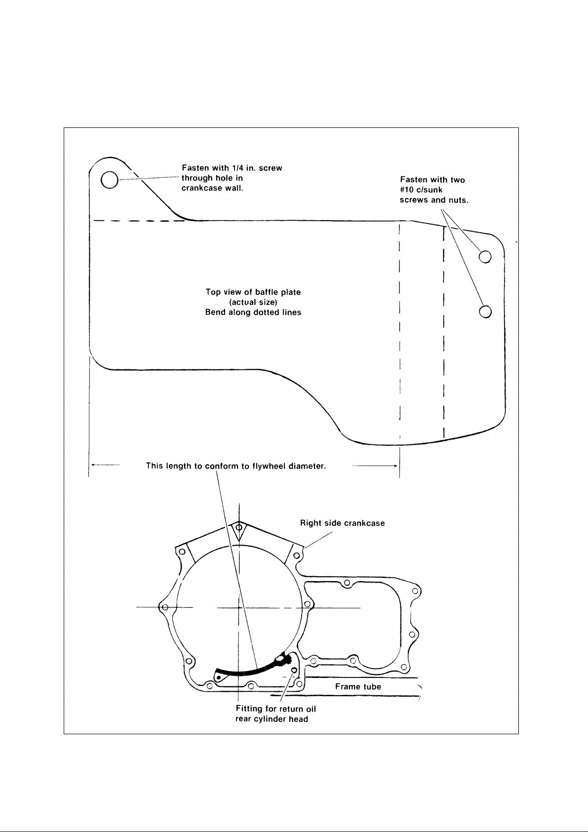
OILING SYSTEM See Figure 2 Add baffle plate to crankcase
sump as shown.
Figure 2. Oil System Modifications
Page 4
Change return oil line from rear cylinder head to drain directly into
sump For this a 1/8 in. taper pipe thread hose fitting has to he
installed in the right crankcase (see bottom view of Figure 2).
Locate this fitting with engine mounted in the frame.
CYLINDER BASE GASKET
Eliminate the gasket use Dow Corning 732 silicone sealant.
Proper placement will be above the lower frame tube and behind
the vertical crankcase boss for oil pick-up hole.
To reduce oil flow to the connecting rod bearing a restrictor
should be pressed into the pinion shaft One way to make this
would be to machine the thread off a carburetor main jet (A main
jet from an MX, SS or SX carburetor may have the following
dimensions.)
Pinion shaft hole size 0.19 ± 0.02 in.
Restrictor hole size 0.090 in.
Transmission
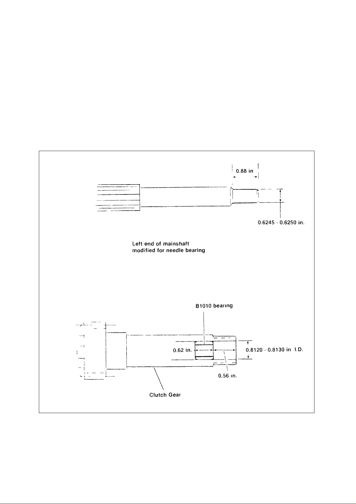
In road racing 1st 2nd and 3rd gears are used more frequently
than in normal street use The bushing in the clutch gear is
subjected to higher speeds and must be packed in grease or in its
place a needle bearing (Torrington #B1010) can be installed. See
Figure 3. To allow use of the needle bearing the mainshaft must
be ground to dimensions shown Remove stock bushing and press
needle bearing into clutch gear as shown.
Figure 3. Transmission Modification
Page 5

SHIFTER MECHANISM
The shifter forks are subjected to heavy loads. This can be reduced
by carefully modifying the shifter cam plate. See Figure 4. The
removal of metal at the shaded areas of cam plate will allow more
engagement of the gears. In order to find out where and how much
material has to be removed, put transmission in each of the four
gears and recheck for each gear, what is required to make the
gears engage more completely. Figure 4 shows where metal must
be removed, if necessary.
Remove a little metal at a time and recheck engagement of gears.
Repeat until gears are fully engaged with one another.
Shifter forks should be free while holding gears together.
Shifter cam grooves and outside surface where plunger rides,
should be polished for smoother operation.
Remove countershaft oiler plug on transmission door to eliminate
the chance of it coming out.
A close ratio 3rd gear ("C" ratio) is available from Andrews
Products.
Figure 4. Shifter Plate Modification
Page 6

Clutch Modifications
To improve operation of the clutch, more oil must be allowed to
flow through. The following operations are recommended.
CLUTCH SHELL
See Figure 5. To sling oil out of the clutch, drill two 0.19 in.
diameter evenly spaced holes in each driving groove (24 holes
total). Drill three 0.38 in. diameter equally spaced holes in back
plate.
Figure 5. Clutch Shell Holes
Page 7

CLUTCH HUB
See Figure 6. Drill a diagonal pattern of six 0.09 in. diameter holes
all around hub while taking care that the
no. 3 and no. 5 holes do not run out into hub center plate. Seven
0.25 in. diameter holes must be drilled flush with inside diameter
(I.D.) of hub rim (where no. 4 holes break through).
Figure 6. Clutch Hub Holes
Page 8

Figure 7. Clutch Release Disc Modification
Modification, Clutch Release Disc
See figure 7. In order to circulate more oil through the clutch,
three scoops must be added to the clutch release disc.
Fabricate the scoops from light gauge steel sheet metal. Drill
three 0.375 in holes through the clutch release disc. Position the
scoops and weld them in place.
Page 9

Overall Gear Ratios
RANGE
HOT
N4C
R
*
1056
The overall qear ratios with various sprockets are listed in the
following chart.
Speed Formula
HourMiles
/ =
CS
*
REAR WHEEL
SPROCKET
(TEETH)
40 3.65 3.47 3.31
41 3.74 3.56 3.39
42 3.84 3.64 3.47
43 3.93 3.73 3.55
44 4.02 3.82 3.64
45 4.11 3.90 3.72
46 4.20 3.99 3.80
Transmission sprockets with 79 and 20 teeth require a
0.090 in. thick spacer.
PART HARLEY-DAVIDSON PART NUMBER
19 T Transmission Sprocket 35197-52
20 T Transmission Sprocket 35198-52
21 T Transmission Sprocket 35205-52A
TRANSMISSION
SPROCKET
(TEETH)
19 20 21
Overall Gear Ratios
NOTE
S = Engine RPM
C = Tire circumference (inches)
R = Overall Gear Ratio
Average gearing for Stock bikes 3.84
Ignition Timing
For Stock and Modified classes full advance ignition timing is 30°
BTDC above 2000 RPM.
Spark Plugs and Cables
If stock Magnavox ignition is used also use resistor spark plugs
and stock carbon core spark plug cables. This will prevent
problems with electronic ignition module and tachometer.
Champion resistor spark plugs are identified by the letter R in
front of spark plug type ie. RN6YC.
Spark plug gap should be closed up to 0.022 in (Stock and
Modified classes).
Since the heat range required for each cylinder may not be the
same it is necessary to take plug readings on both cylinders. See
spark plug chart for heat ranges.
HEAT
PROJECTED PROJECTED REGULAR FINE WIRE RETRACTED
RN7YC N7YC HEAT
N3C N87 RANGE
RN6YC N6YC
N2C N86 N62R G63R STOCK
N4YC &
N60 N84 N60R G61R MOD.
G59R
COLD N57 N82 N57R G58R
14 mm 10 mm
RACING HEAT RANGE CHART FOR CHAMPION
SPARK PLUGS
Page 10

See Figure 8. The engine will run cooler with an additional
spark plug installed on the right side of the cylinder head.
With two (2) plugs installed, make the following changes:
Ignition Timing 17-20° BTDC
Gap 14 mm Plug 0.018 in.
Gap 10mm Plug* 0.015 in.
*See spark plug chart for recommended 10 mm plugs.
Connect two coils in parallel to make all plugs fire at the same
time.
Figure 8. Installing Additional Spark Plug
Page 11

Carburetion
For best results jet both carburetors individually.
The accelerator pump should be disconnected by removing the
plastic lever (cam follower) from the carburetor cover.
If stock mufflers are repaced by megaphones the main jets
have to be increased by approximately two sizes.
D’Ellorto 36 mm 40 mm
Main Jet 140-155 145-160
Slide 50/3 60/5
Needle K27 K4
THROTTLE
The throttle should be lubricated with Bel Ray 6 in 1 oil. Do
not use dry slide lubricant.
FUEL VALVE
Remove stand pipe in fuel valve and turn knob to reserve for
maximum fuel flow.
IGNITION SWITCH
Pack wire on the back of switch in RT\/ silicon sealant to prevent it
from breaking.
REAR SET FOOTRESTS
Raise master cylinder 2½ in. and turn brake and shifter levers
around.
For the new location of the footrests use a rear footrest support
from a 1982 XL.
Needle Jet 262AB 265AB
Idle Jet 62-65 62-65
Suppliers for D’Ellorto carbs and parts is Cosmopolitan Motors.
Forty-one mm Lectron carburetors and tapered manifolds are
available from Branch Flowmetrics.
Specially modified flat slide Mikuni carburetors are available from
Storz Performance.
Chassis
Front fork: Use 20W fork oil. To check oil level in fork Iegs,
remove springs and bottom out the suspension. The distance
from the top of the fork to the oil level should be 5.8 in. with the
suspension bottomed out. Be sure spring is free from oil at the
time of installation.
See figure 9. To increase compression damping, one of the
two 0.24 in. diameter holes in the fork damper tube has to be
PART HARLEY-DAVIDSON PART NUMBER
Footrest Support (1) 52706-82
Footrest (2) 33048-72
Locknut (2) 7778
Bo!t (2) 4721
A rear swingarm mounted footrest kit is available for the XL
models and can also be used for the XR-1000. Order HarleyDavidson Part No. 49105-83.
HANDLEBARS, STOCK CLASS ONLY
Upside down mounted handlebars from a 1983 XLS, or HarleyDavidson Draqbike handlebars work very well. If the dragbike
bars are used, a notch must be made in the switch housing to
prevent the wires from being cut.
PART HARLEY-DAVIDSON PART NUMBER
XLS Handlebar 56082-83
Draqbike Handlebar 55963-77
REAR FENDER
Flatten rivets on bottom side of rear fender to prevent
interference with tire.
plugged.
F igure 9 Fork Damper Tube Modification
REAR SHOCKS
The following shocks and springs are recommended:
Shock: Koni #7610F-1283 (13½ in. Ig.)
Spring: Koni #250-15-21-28
Supplier - Parts Unlimited
KICK STAND
The kick stand must be removed.
Exhaust Pipes
The Harley-Davidson part number for the exhaust pipe kit is
80078-83.
To prevent cracking exhaust pipes must be mounted without
stress.
Modified class: Springs can be used to. mount header pipes and
hold joints together. Interconnector can have slip fit.
Page 12

Fuel
Stock Class: The use of racing gasoline is recommended.
However, a premium leaded or unleaded gasoline with a
minimum octane rating of 92 is satisfactory.
Modified Class: Use racing gasoline only.
Oil
Engine:
HD20W50 Power Blend. (Mineral Oil)
40W Racing Oil (Mineral Oil)
40W Castor Oil (Vegetable Oil)
Transmission: Racing automatic transmission fluid
(available at automotive performance shops).
OIL FILTER
The oil filter must be safety wired. A hose clamp secured to
the outside of the filter provides a means for safety wiring the
filter.
Suppliers
Andrews Products
5212 North Shapland Avenue Rosemont, IL 60018
312-992-4014
Branch Flowmetrics
5556 Corporate Drive Cypress, CA 90623
714-827-1463
C. R. Axtell
10949 Tuxford Street, #17
Sun Valley, CA 91352
213-768-5594
Cosmopolitan Motors
Jacksonville & Meadowbrook Roads
Hatboro, PA 19040
215-672-9100
Parts Unlimited
P. 0. Box 9238
Ashevilie, NC 28805
S & S Cycle
Route 2, County G
Viola, Wl 54664
608-627-1497
Storz Performance
1362 Tower Square, #2
Ventura, CA 93003
805-654-8816
 Loading...