

Page 1
Safety First
Page
1
of 82008 Touring Models Owner's Manual: Safety First
8/
30/
2012
https://www.harley
-
davidson.com/en_US/Content/Pages/Owners/om/2008/en/TOURING/f
...
Safe Operating Rules: Touring Models
Motorcycles are different from other vehicles. They operate, steer, handle and
brake differently. Unskilled or improper use could result in loss of control,
death or serious injury. (00556c)
z Take a rider training course.
z Read Owner's Manual before riding, adding accessories or servicing.
z Wear a helmet, eye protection and protective clothing.
z Never tow a trailer.
Before operating your new motorcycle it is your responsibility to read and follow the operating and
maintenance instructions in this manual, and follow these basic rules for your personal safety.
z Know and respect the rules of the road (see RULES OF THE ROAD section). Carefully read
and observe the rules contained in the RIDING TIPS booklet accompanying this Owner's
Manual. Read and familiarize yourself with the contents of the MOTORCYCLE HANDBOOK for
your state.
z Before starting engine, check for proper operation of brake, clutch, shifter, throttle controls,
correct fuel and oil supply.
Do not use aftermarket parts and custom made front forks which can adversely
affect performance and handling. Removing or altering factory installed parts
can adversely affect performance and could result in death or serious injury.
(00001a)
z Use only Harley-Davidson approved parts and accessories. Use of certain other
manufacturer's performance parts will void your new motorcycle warranty. See your HarleyDavidson dealer for details.
Stop the engine when refueling or servicing the fuel system. Do not smoke or
allow open flame or sparks near gasoline. Gasoline is extremely flammable and
highly explosive, which could result in death or serious injury. (00002a)
When refueling your motorcycle, the following rules should be observed.
z Refuel in a well ventilated area with the engine turned off.
Page 2

z Remove fuel filler cap slowly.
Page
2
of 82008 Touring Models Owner's Manual: Safety First
8/
30/
2012
https://www.harley
-
davidson.com/en_US/Content/Pages/Owners/om/2008/en/TOURING/f
...
z Do not smoke or allow open flames or sparks when refueling or servicing the fuel system.
z Do not fill fuel tank above the bottom of the filler neck insert.
z Leave air space to allow for fuel expansion.
Do not store motorcycle with gasoline in tank within the home or garage where
open flames, pilot lights, sparks or electric motors are present. Gasoline is
extremely flammable and highly explosive, which could result in death or
serious injury. (00003a)
Engine exhaust from this product contains chemicals known to the State of
California to cause cancer, and birth defects or other reproductive harm.
(00004f)
Wheel weights on wheels without spokes contain lead and lead compounds,
chemicals known to the State of California to cause cancer, and birth defects or
other reproductive harm. (00356d)
Do not run motorcycle in a closed garage or confined area. Inhaling motorcycle
exhaust, which contains poisonous carbon monoxide gas, could result in death
or serious injury. (00005a)
The jiffy stand locks when placed in the full forward (down) position with
vehicle weight on it. If the jiffy stand is not in the full forward (down) position
with vehicle weight on it, the vehicle can fall over which could result in death
or serious injury. (00006a)
Be sure jiffy stand is fully retracted before riding. If jiffy stand is not fully
retracted, it can contact the road surface causing a loss of vehicle control,
which could result in death or serious injury. (00007a)
z A new motorcycle must be operated according to the special break-in procedure. See
Break-in Riding Rules.
z Operate motorcycle only at moderate speed and out of traffic until you have become
thoroughly familiar with its operation and handling characteristics under all conditions.
NOTE:
We recommend that you obtain information and formal training in the correct motorcycle riding
technique. In the United States, the Motorcycle Safety Foundation®offers beginning and advanced
rider safety courses. Call (949)727-3227 for information.
Page 3

Travel at speeds appropriate for road and conditions and never travel faster
Page
3
of 82008 Touring Models Owner's Manual: Safety First
8/
30/
2012
https://www.harley
-
davidson.com/en_US/Content/Pages/Owners/om/2008/en/TOURING/f
...
than posted speed limit. Excessive speed can cause loss of vehicle control,
which could result in death or serious injury. (00008a)
z Do not exceed the legal speed limit or drive too fast for existing conditions. Always reduce
speed when poor driving conditions exist. High speed increases the influence of any other
condition affecting stability and increases the possibility of loss of control.
z Pay strict attention to road surfaces and wind conditions. Any two wheeled vehicle may be
subject to upsetting forces such as wind blasts from passing trucks, holes in the pavement,
rough road surfaces, rider control error, etc. These forces may influence the handling
characteristics of your motorcycle. If this happens, reduce speed and guide the motorcycle
with a relaxed grip to a controlled condition. Do not brake abruptly or force the handlebar.
This may aggravate an unstable condition.
z Keep cargo weight concentrated close to the motorcycle and as low as possible to minimize
the change in the motorcycle's center of gravity. Distribute weight evenly on both sides of
the vehicle and do not load bulky items too far behind the rider or add weight to the
handlebars or front forks. Do not exceed maximum specified load in each saddlebag.
NOTE:
New riders should gain experience under various conditions while driving at moderate speeds.
z Operate your motorcycle defensively. Remember, a motorcycle does not afford the same
protection as an automobile in an accident. One of the most common accident situations
occurs when the driver of the other vehicle fails to see or recognize a motorcycle and turns
left into the on-coming motorcyclist. Operate only with headlamp on.
z Wear an approved helmet, clothing, and foot gear suited for motorcycle riding. Bright or
light colors are best for greater visibility in traffic, especially at night. Avoid loose, flowing
garments and scarves.
Avoid contact with exhaust system and wear protective clothing that
completely covers legs while riding. Exhaust pipes and mufflers get very hot
when engine is running and remain too hot to touch, even after engine is
turned off. Failure to wear protective clothing could result in burns or other
serious injury. (00009a)
z When carrying passengers, it is your responsibility to instruct them on proper riding
procedures. (See Riding Tips for Motorcyclist included in your Harley-Davidson Owner's Kit.)
z Do not allow other individuals, under any circumstances, to operate your motorcycle unless
you know they are experienced, licensed riders and are thoroughly familiar with the
operation of your particular motorcycle.
z Protect your motorcycle against theft. After parking your motorcycle, lock the steering head
and remove ignition key from switch. Set security alarm if present.
z Safe motorcycle operation requires alert mental judgment combined with a defensive
driving attitude. Do not allow fatigue, alcohol or drugs to endanger your safety or that of
others.
z Vehicles equipped with a sound system should have the volume adjusted to a
nondistracting level before operating vehicle.
z Maintain your motorcycle in proper operating condition in accordance with Regular Service
Intervals: 2008 Touring Models. Particularly important to motorcycle stability is proper
tire inflation pressure, tread condition, and proper adjustment of wheel bearings and
Page 4

steering head bearings.
Page
4
of 82008 Touring Models Owner's Manual: Safety First
8/
30/
2012
https://www.harley
-
davidson.com/en_US/Content/Pages/Owners/om/2008/en/TOURING/f
...
Do not operate vehicle with forks locked. Locking the forks restricts the
vehicle's turning ability, which could result in death or serious injury. (00035a)
Perform the service and maintenance operations as indicated in the regular
service interval table. Lack of regular maintenance at the recommended
intervals can affect the safe operation of your motorcycle, which could result in
death or serious injury. (00010a)
Do not operate motorcycle with loose, worn or damaged steering or suspension
systems. Contact a Harley-Davidson dealer for repairs. Loose, worn or damaged
steering or suspension components can adversely affect stability and handling,
which could result in death or serious injury. (00011a)
Regularly inspect shock absorbers and front forks. Replace leaking, damaged or
worn parts that can adversely affect stability and handling, which could result
in death or serious injury. (00012a)
Use Harley-Davidson replacement fasteners. Aftermarket fasteners can
adversely affect performance, which could result in death or serious injury.
(00013a)
z See your Harley-Davidson service manual for proper torque values.
z Aftermarket fasteners may not have the specific property requirements to perform properly.
Be sure tires are properly inflated, balanced and have adequate tread. Inspect
your tires regularly and see a Harley-Davidson dealer for replacements. Riding
with excessively worn, unbalanced or under-inflated tires can adversely affect
stability and handling, which could result in death or serious injury. (00014a)
Replace punctured or damaged tires. In some cases, small punctures in the
tread area may be repaired from within the demounted tire by a HarleyDavidson dealer. Speed should NOT exceed 50 mph (80 km/h) for the first 24
hours after repair, and the repaired tire should NEVER be used over 80 mph
(130 km/h). Failure to follow this warning could result in death or serious
injury. (00015a)
Page 5
Do not exceed the motorcycle's Gross Vehicle Weight Rating (GVWR) or Gross
Page
5
of 82008 Touring Models Owner's Manual: Safety First
8/
30/
2012
https://www.harley
-
davidson.com/en_US/Content/Pages/Owners/om/2008/en/TOURING/f
...
Axle Weight Rating (GAWR). Exceeding these weight ratings can affect stability
and handling, which could result in death or serious injury. (00016e)
z GVWR is the sum of the weight of the motorcycle, accessories, and the maximum weight of
the rider, passenger and cargo that can be safely carried.
z GAWR is the maximum amount of weight that can be safely carried on each axle.
z The GVWR and GAWR are shown on the information plate located on the frame steering
head.
Do not tow a disabled motorcycle. Towing can adversely affect stability and
handling, which could result in death or serious injury. (00017a)
Do not pull a trailer with a motorcycle. Pulling a trailer can cause tire overload,
reduced braking efficiency and adversely affect stability and handling, which
could result in death or serious injury. (00018b)
Direct contact of D.O.T. 4 brake fluid with eyes can cause irritation. Avoid eye
contact. In case of eye contact flush with large amounts of water and get
medical attention. Swallowing large amounts of D.O.T. 4 brake fluid can cause
digestive discomfort. If swallowed, obtain medical attention. Use in well
ventilated area. KEEP OUT OF REACH OF CHILDREN. (00240a)
Batteries, battery posts, terminals and related accessories contain lead and
lead compounds, and other chemicals known to the State of California to cause
cancer, and birth defects or other reproductive harm. Wash hands after
handling. (00019e)
Consult a Harley-Davidson dealer regarding any questions or problems that
occur in the operation of your motorcycle. Failure to do so can aggravate an
initial problem, cause costly repairs, cause an accident and could result in
death or serious injury. (00020a)
z Be sure all equipment required by federal, state and local law is installed and in good
operating condition.
Do not open storage compartments while riding. Distractions while riding can
Page 6

lead to loss of control, which could result in death or serious injury. (00082a)
Page
6
of 82008 Touring Models Owner's Manual: Safety First
8/
30/
2012
https://www.harley
-
davidson.com/en_US/Content/Pages/Owners/om/2008/en/TOURING/f
...
If ABS lamp remains on continuously, the ABS is not operating. The standard
brake system is operational, but wheel lock up can occur. Contact a HarleyDavidson Dealer to have ABS repaired. A locked wheel will skid and can cause
loss of vehicle control, which could result in death or serious injury. (00361a)
ABS cannot prevent lockup of rear wheel due to engine braking. ABS will not
aid in cornering or on loose/uneven surfaces. A locked wheel will skid and can
cause loss of vehicle control, which could result in death or serious injury.
(00362a)
Rules of the Road
z Always sound your horn, actuate your turn signals, and exercise caution when passing
other vehicles going in the same direction. Never try to pass another vehicle going in the
same direction at street intersections, on curves, or when going up or down a hill.
z At street intersections give the right-of-way. Do not presume you have the right-of-way, as
the other driver may not know it is your turn.
z Always signal when preparing to stop, turn or pass.
z All traffic signs, including those used for the control of traffic at intersections, should be
obeyed promptly. SLOW DOWN signs near schools and CAUTION signs at railroad crossings
should always be observed and your actions governed accordingly.
z When intending to turn, signal at least 100 feet 30.5 meters before reaching the turning
point. If turning across an intersection, move over to the centerline of the street (unless
local rules require otherwise). Slow down when entering the intersection and turn carefully.
z Never anticipate a traffic light. When a change is indicated from GO to STOP (or vice versa)
in the traffic control systems at intersections, slow down and wait for the light to change.
Never run through a yellow or red traffic light.
z While turning either right or left, watch for pedestrians, animals, as well as vehicles.
z Do not leave the curb or parking area without signaling. Be sure your way is clear to enter
moving traffic. A moving line of traffic always has the right-of-way.
z Be sure your license plate is installed in the position specified by law and is clearly visible at
all times. Keep the plate clean.
z Ride at a safe speed that is consistent with the type of highway you are on. Pay strict
attention to whether the road is dry, oily, icy or wet.
z Watch for debris such as leaves or loose gravel.
z Weather and traffic conditions on the highway dictate adjusting your speed and driving
habits accordingly.
Accessories and Cargo
Harley-Davidson Motor Company cannot test and make specific recommendations concerning every
accessory or combination of accessories sold. Therefore, the rider must be responsible for safe
operation of the motorcycle when installing accessories or carrying additional weight.
Page 7

See the Accessory and Cargo section in your Owner's Manual. Improper loading
Page
7
of 82008 Touring Models Owner's Manual: Safety First
8/
30/
2012
https://www.harley
-
davidson.com/en_US/Content/Pages/Owners/om/2008/en/TOURING/f
...
of cargo or installation of accessories can affect motorcycle stability and
handling, which could result in death or serious injury. (00021a)
Do not exceed the motorcycle's Gross Vehicle Weight Rating (GVWR) or Gross
Axle Weight Rating (GAWR). Exceeding these weight ratings can affect stability
and handling, which could result in death or serious injury. (00016e)
z GVWR is the sum of the weight of the motorcycle, accessories, and the maximum weight of
the rider, passenger and cargo that can be safely carried.
z GAWR is the maximum amount of weight that can be safely carried on each axle.
z The GVWR and GAWR are shown on the information plate which is located on the frame
down tube.
Do not pull a trailer with a motorcycle. Pulling a trailer can cause tire overload,
reduced braking efficiency and adversely affect stability and handling, which
could result in death or serious injury. (00018b)
Accessory and Cargo Guidelines
The following guidelines should be used when equipping a motorcycle, carrying passengers and/or
cargo.
Travel at speeds appropriate for road and conditions and never travel faster
than posted speed limit. Excessive speed can cause loss of vehicle control,
which could result in death or serious injury. (00008a)
z Do not exceed the legal speed limit or drive too fast for existing conditions. Always reduce
speed when poor driving conditions exist. High speed increases the influence of any other
condition affecting stability and increases the possibility of loss of control.
z Pay strict attention to road surfaces and wind conditions. Any two wheeled vehicle may be
subject to upsetting forces such as wind blasts from passing trucks, holes in the pavement,
rough road surfaces, rider control error, etc. These forces may influence the handling
characteristics of your motorcycle. If this happens, reduce speed and guide the motorcycle
with a relaxed grip to a controlled condition. Do not brake abruptly or force the handlebar.
This may aggravate an unstable condition.
z Keep cargo weight concentrated close to the motorcycle and as low as possible. This
minimizes the change in the motorcycle's center of gravity.
z Distribute weight evenly on both sides of the vehicle.
z Do not load bulky items too far behind the rider or add weight to the handlebars or front
forks.
Page 8
z Do not exceed maximum specified load in each saddlebag.
Page
8
of 82008 Touring Models Owner's Manual: Safety First
8/
30/
2012
https://www.harley
-
davidson.com/en_US/Content/Pages/Owners/om/2008/en/TOURING/f
...
z Luggage racks are designed for lightweight items. Do not overload racks.
z Be sure cargo is secure and will not shift while riding and recheck the cargo periodically.
Accessories that change the operator's riding position may increase reaction time and affect
handling of the motorcycle.
z Additional electrical equipment may overload the motorcycle's electrical system possibly
resulting in electrical system and/or component failure.
The front and/or rear guard(s) can provide limited leg and cosmetic vehicle
protection under unique circumstances. (Fall over while stopped, very slow
speed slide.) It is not made or intended to provide protection from bodily injury
in a collision with another vehicle or any other object. (00022a)
Large surfaces such as fairings, windshields, back rests, and luggage racks can adversely affect
handling. Only genuine Harley-Davidson items designed specifically for the motorcycle model
should be used with proper installation.
Do not use aftermarket parts and custom made front forks which can adversely
affect performance and handling. Removing or altering factory installed parts
can adversely affect performance and could result in death or serious injury.
(00001a)
Only Touring Harley-Davidson Motorcycles are suitable for sidecar use. Consult
a Harley-Davidson dealer. Use of motorcycles other than Touring models with
sidecars could result in death or serious injury. (00040a)
Noise Control System
Tampering
Owners are warned that removal or replacement of any noise control system component may be
prohibited by law. This prohibition applies prior to vehicle sale or delivery to the ultimate purchaser.
Use of a vehicle on which noise control system components have been removed or rendered
inoperative may also be prohibited by law.
Page 9
Identification
Page
1
of 32008 Touring Models Owner's Manual: Identification
8/
30/
2012
https://www.harley
-
davidson.com/en_US/Content/Pages/Owners/om/2008/en/TOURING/f
...
Vehicle Identification Number: Touring Models
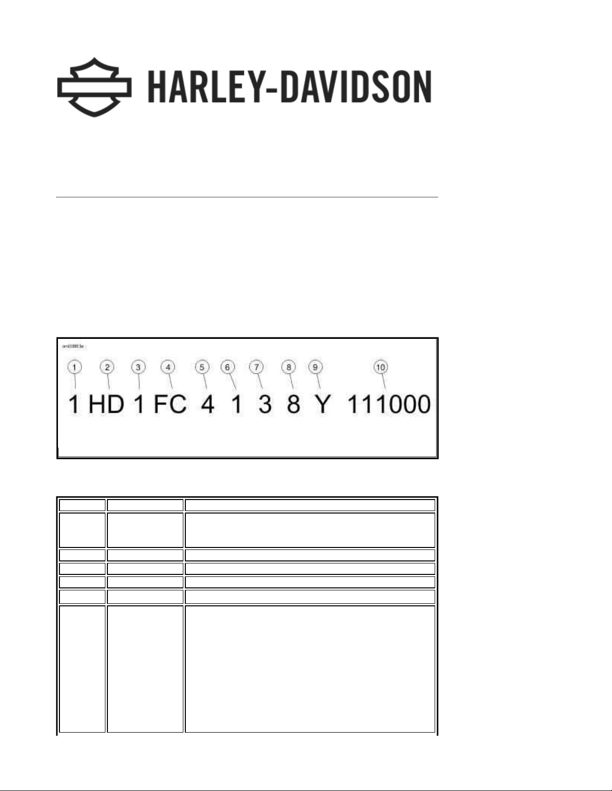
The full 17-digit serial or Vehicle Identification Number (V.I.N.) is stamped on the right side of the
frame backbone at the rear of the frame behind the steering head. A label bearing the V.I.N. code is
also affixed to the left side of the frame behind the steering head.
An abbreviated V.I.N. is stamped on the left side crankcase at the base of the rear cylinder.
NOTE:
Always give the full 17-digit Vehicle Identification Number when ordering parts or making any
inquiry about your motorcycle.
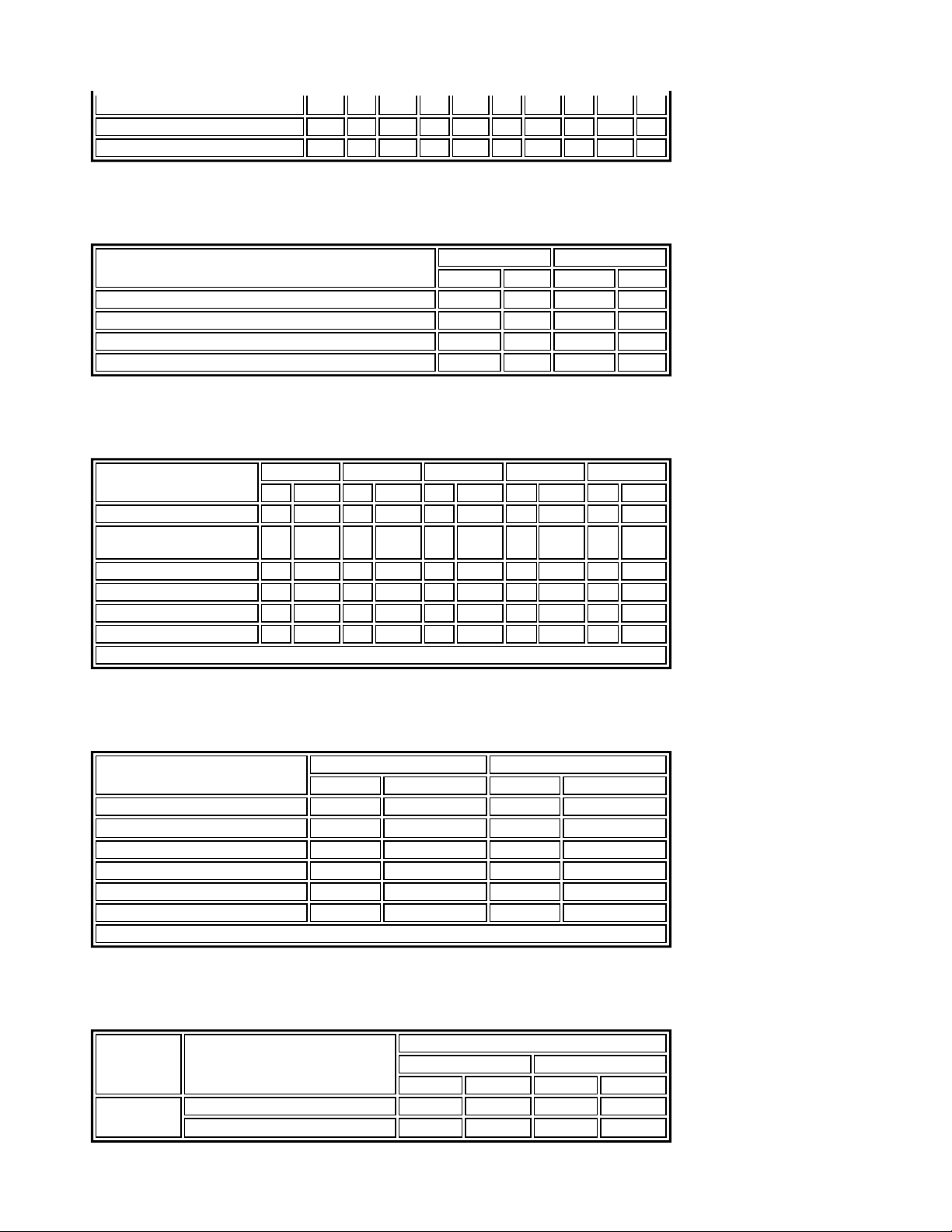
Typical Harley-Davidson V.I.N.: 2008 Touring Models
Harley-Davidson V.I.N. Breakdown: 2008 Touring Models
POSITION DESCRIPTION POSSIBLE VALUES
1 Market designation 1=Originally manufactured for sale within the United States
5=Originally manufactured for sale outside of the United States
2 Manufacturer HD=Harley-Davidson
3 Motorcycle type 1=Heavyweight motorcycle (901 cc or larger)
4 Model See V.I.N. model table
5 Engine type
6 Introduction date 1=Regular
4=Twin Cam 96™, 1584 cc air cooled, fuel injected
2=Mid-year
3=California/regular
4=Cosmetic changes and/or special introductory date
5=California/cosmetic changes and/or special introductory date
6=California/mid-year
Page 10
7 V.I.N. check digit Can be 0-9 or X
Page
2
of 32008 Touring Models Owner's Manual: Identification
8/
30/
2012
https://www.harley
-
davidson.com/en_US/Content/Pages/Owners/om/2008/en/TOURING/f
...
8 Model year 8=2008
9 Assembly plant Y=York, PA U.S.A.
10 Sequential number Varies
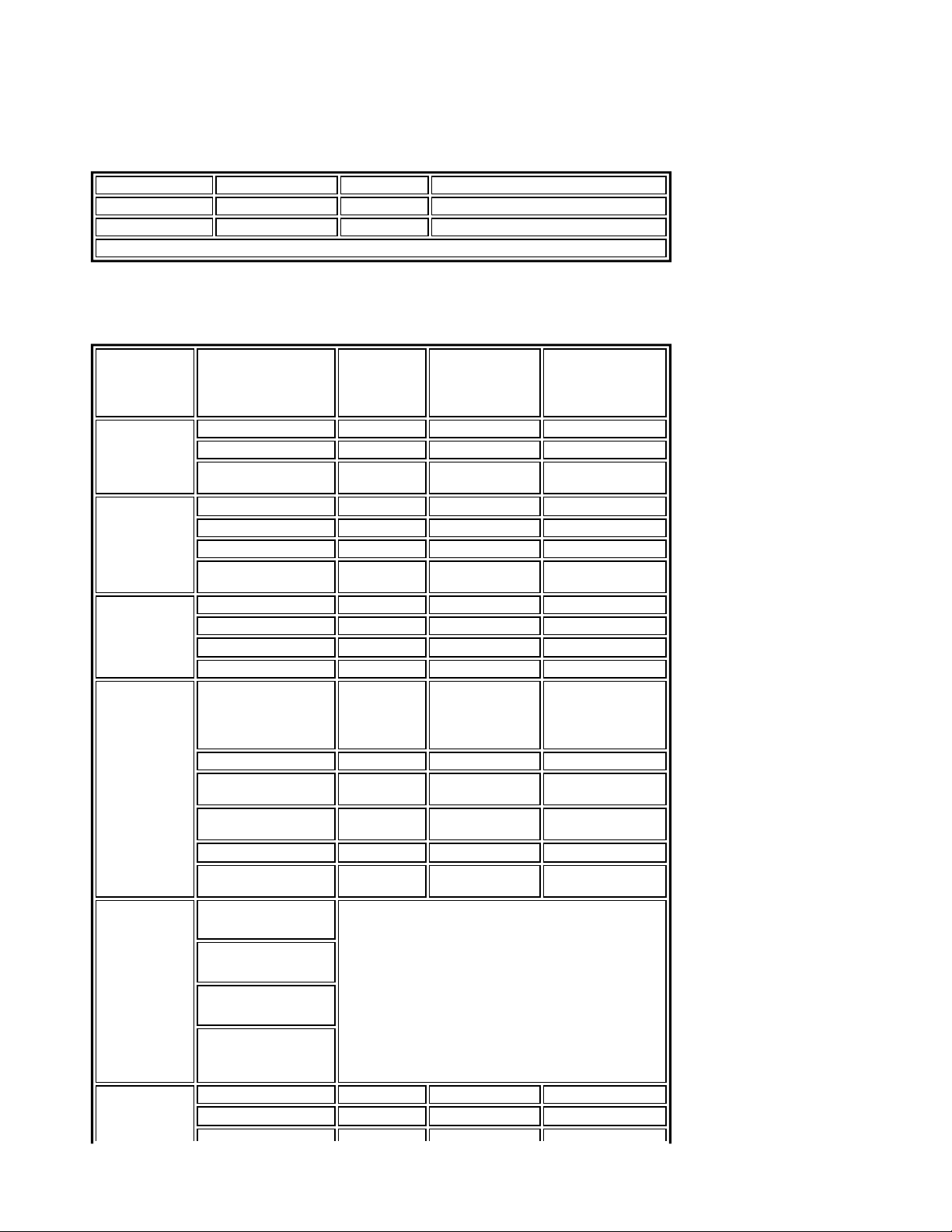
V.I.N. Model Codes: 2008 Touring Models
CODE MODEL CODE MODEL
FB
FLHR Road King
FG
FLHTCU Ultra Classic®Electra Glide®with
sidecar
FS
FLTR Road Glide
FF
FLHTC Electra Glide®Classic
FW
FLHR Road King®Shrine
®
®
FC
FLHTCU Ultra Classic®Electra Glide
FL
FLHTCU Ultra Classic®Electra Glide
Shrine
FV
FLHT Electra Glide®Standard
KB
FLHX Street Glide
FR
FLHRC Road King®Classic
Labels
®
®
™
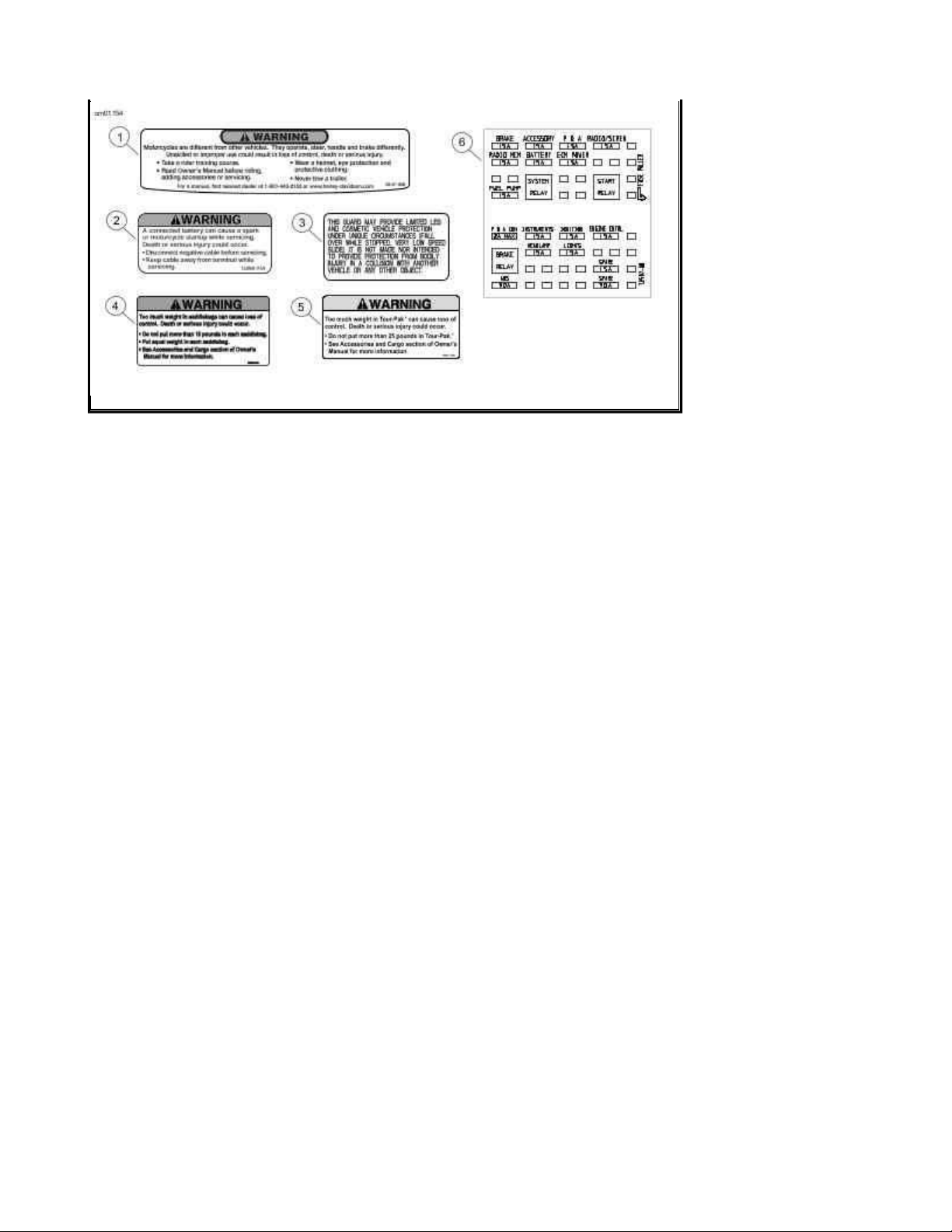
See Labels: Touring Models for safety and maintenance labels which were on the vehicle when
new. If removed, replacement labels may be purchased for your motorcycle. Refer to Labels:
Touring Models for label descriptions.
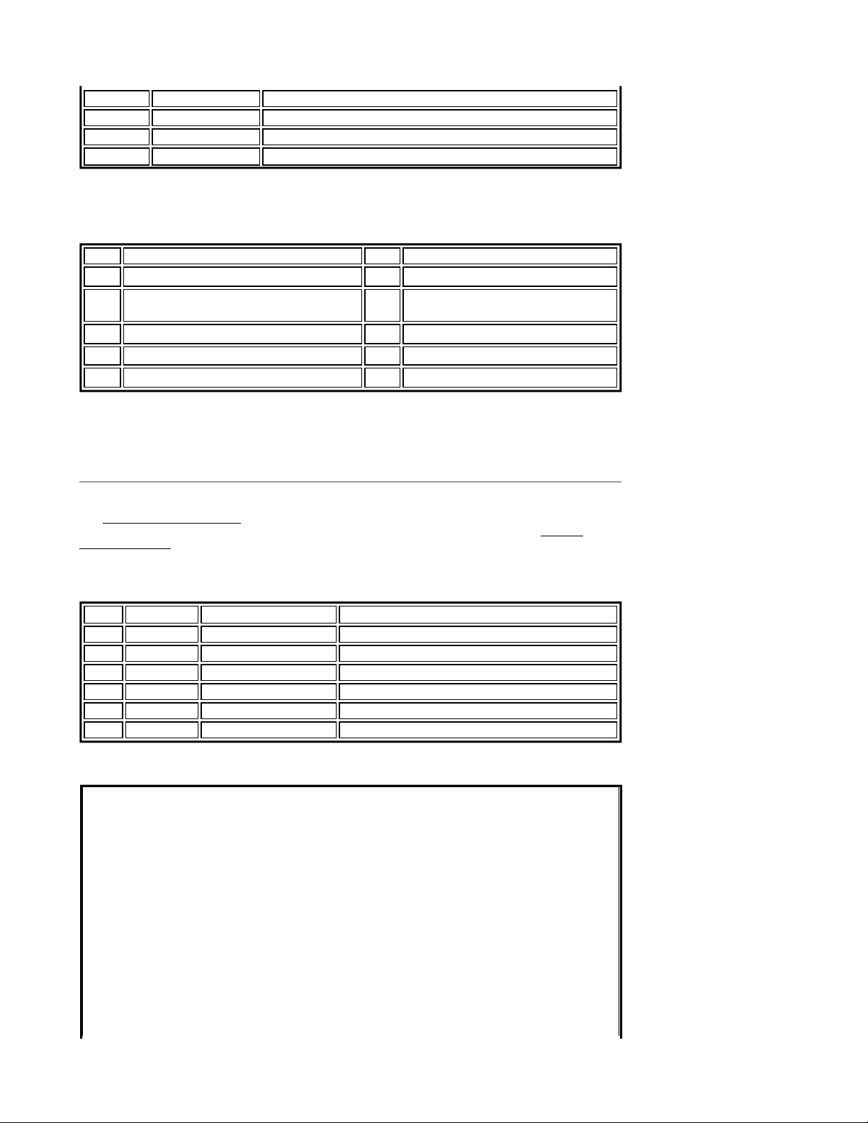
Labels: Touring Models
ITEM PART NO. DESCRIPTION LOCATION
1 29127-95B General warnings Top of air cleaner cover
2 15368-01A Battery warning Under seat, right side of frame
3 14148-86 Highway bar warning On front of highway bar below center mount
4 90820-93C Saddlebag load limits Inside saddlebag.
5 90821-74B Tour-Pak load limits Inside Tour-Pak lid.
6 72537-08 Fuse block cover Under left side cover on fuse block
Page 11
Labels: Touring Models
Page
3
of 32008 Touring Models Owner's Manual: Identification
8/
30/
2012
https://www.harley
-
davidson.com/en_US/Content/Pages/Owners/om/2008/en/TOURING/f
...
Page 12
Specifications
Page
1
of 72008 Touring Models Owner's Manual: Specifications
8/
30/
2012
https://www.harley
-
davidson.com/en_US/Content/Pages/Owners/om/2008/en/TOURING/f
...
Specifications: 2008 Touring Models
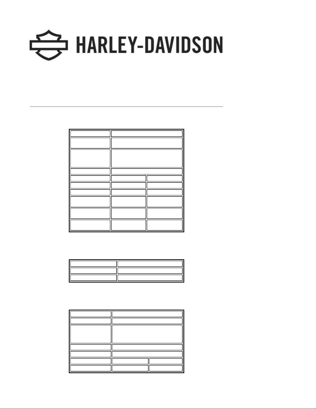
Engine: 2008 Touring Models
ITEM SPECIFICATION
Number of
cylinders
Type 4-cycle, 45 degree
V-Type, air cooled
Compression ratio 9.2-1
Bore 3.750 in. 95.25 mm
Stroke 4.380 in. 111.25 mm
Displacement 96 cu. in. 1584 cc
Torque (North
America)
Torque
(International)
Torque (Japan) 86.90 ft-lbs @
92.60 ft-lbs @
3500 RPM
90.20 ft-lbs @
3400 RPM
2500 RPM
2
125.57 Nm @
122.31 Nm @
117.84 Nm @
3500 RPM
3400 RPM
2500 RPM
Transmission: 2008 Touring Models
TRANSMISSION SPECIFICATION
Type Constant mesh, foot shift
Speeds 6 forward
Ignition System: 2008 Touring Models
COMPONENT SPECIFICATION
Ignition timing Not adjustable
Battery 12 volt, 28 amp/hr, 270 CCA
sealed and maintenance free
Spark plug type HD-6R12
Spark plug size 12 mm
Spark plug gap 0.038-0.043 in. 0.97-1.09 mm
Spark plug torque 12-18 ft-lbs 16.3-24.4 Nm
Page 13
NOTE:
Page
2
of 72008 Touring Models Owner's Manual: Specifications
8/
30/
2012
https://www.harley
-
davidson.com/en_US/Content/Pages/Owners/om/2008/en/TOURING/f
...
Specifications in this publication may not match those of official certification in some markets due
to timing of publication printing, variance in testing methods, and/or vehicle differences.
Customers seeking officially recognized regulatory specifications for their vehicle should refer to
certification documents and/or contact their respective dealer or distributor.
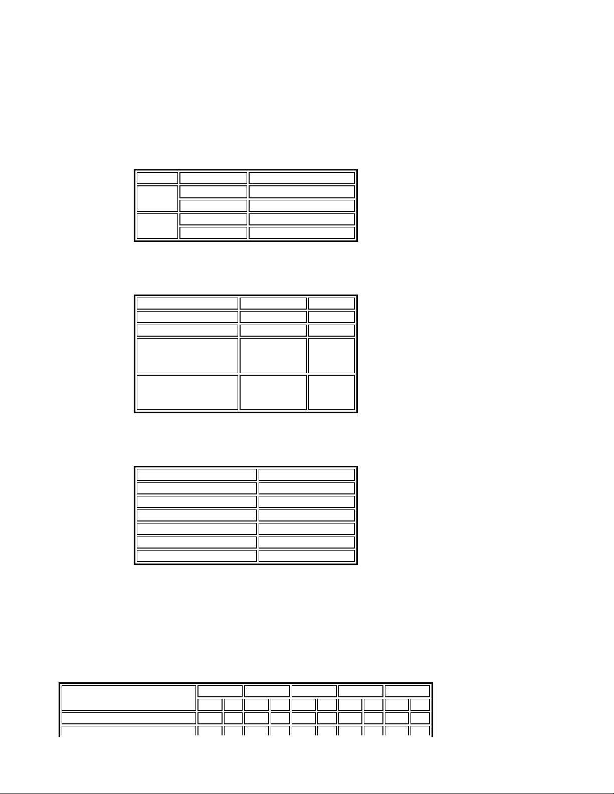
Sprocket Teeth: 2008 Touring Models
DRIVE ITEM NUMBER OF TEETH
Primary Engine 34
Clutch 46
Final Transmission 32
Rear wheel 66
Capacities: 2008 Touring Models
ITEM U.S. LITERS
Fuel tank (total) 6.0 gal 22.7
Oil tank with filter 4.0 U.S. qt. 3.8
Transmission
32.0 fl. oz. 0.95
(approximate)
Primary chaincase
(approximate)
Gear Ratios: 2008 Touring Models
GEAR RATIO
1st Gear 9.312
2nd Gear 6.421
3rd Gear 4.774
4th Gear 3.926
5th Gear 3.279
6th Gear 2.790
NOTE:
Gross Vehicle Weight Rating (GVWR) (maximum allowable loaded vehicle weight) and
corresponding Gross Axle Weight Ratings (GAWR) are listed on a label located on the left side of
the motorcycle on the lower front downtube.
45.0 fl. oz. 1.32
Weights: 2008 FLHT, FLHTC/U, FLTR and FLHX
ITEM FLHT FLHTC FLHTCU FLTR FLHX
LB. KG LB. KG LB. KG LB. KG LB. KG
Weight as shipped from factory 743 337 791 359 814 369 752 341 749 341
Page 14
GVWR 1259 571 1259 571 1259 571 1259 571 1259 571
Page
3
of 72008 Touring Models Owner's Manual: Specifications
8/
30/
2012
https://www.harley
-
davidson.com/en_US/Content/Pages/Owners/om/2008/en/TOURING/f
...
GAWR front 500 227 500 227 500 227 500 227 500 227
GAWR rear 827 375 827 375 827 375 827 375 827 375
Weights: 2008 FLHR and FLHRC
ITEM FLHR FLHRC
LB. KG LB. KG
Weight as shipped from factory 740 336 738 335
GVWR 1259 571 1259 571
GAWR front 500 227 500 227
GAWR rear 827 375 827 375
Dimensions: 2008 FLHT, FLHTC/U, FLTR and FLHX
ITEM FLHT FLHTC FLHTCU FLTR FLHX
IN. MM IN. MM IN. MM IN. MM IN. MM
Wheel base 63.5 1612.9 63.5 1612.9 63.5 1612.9 63.5 1612.9 63.5 1612.9
Overall length (Tour-Pak
in rearmost position)
Overall width 39.0 990.6 39.0 990.6 39.0 990.6 35.8 909.3 39.0 990.6
Road clearance 5.1 129.5 5.1 129.5 5.1 129.5 5.1 129.5 4.7 119.4
Overall height 61.0 1549.4 61.0 1549.4 61.0 1549.4 55.0 1397.0 52.2 1325.9
Saddle height* 27.3 693.4 27.3 693.4 27.3 693.4 26.9 683.3 26.3 668.0
*With 180 lb. (81.7 kg) rider on seat
93.7 2380.0 97.5 2476.5 98.3 2496.8 93.7 2380.0 94.5 2400.3
Dimensions: 2008 FLHR and FLHRC
ITEM FLHR FLHRC
IN. MM IN. MM
Wheel base 63.5 1612.9 63.5 1612.9
Overall length 93.7 2380.0 93.7 2380.0
Overall width 34.5 876.3 34.5 876.3
Road clearance 5.1 129.5 5.1 129.5
Overall height 55.1 1399.5 55.1 1399.5
Saddle height* 27.3 693.4 26.9 683.3
*With 180 lb. (81.7 kg) rider on seat
Tire Pressures: 2008 Touring Models
MODEL LOAD TIRE PRESSURE (COLD)
FRONT REAR
PSI kPa PSI kPa
All Solo rider 36 248 36 248
Rider and passenger 36 248 40 276
Page 15
Tire Sizes: 2008 Touring Models
Page
4
of 72008 Touring Models Owner's Manual: Specifications
8/
30/
2012
https://www.harley
-
davidson.com/en_US/Content/Pages/Owners/om/2008/en/TOURING/f
...
MODEL MOUNT SIZE NUMBER
All front 16 in. D402F MT90B16
All rear 16 in. D402 MU85B16
2008 vehicles use Dunlop Harley-Davidson tires only.
Bulb Chart: 2008 Touring Models
LAMP DESCRIPTION
(ALL LAMPS 12
VOLT)
Headlamp FLHT/C/U, FLHR, FLHX 1 4.58/5.0 68329-03
FLTR 2 4.58/5.0 68329-03
Position lamp
international
Tail and stop
lamp
Turn signal
lamp
Additional
lighting
Instrument
panel lamps
Tail lamp 1 0.59 68167-04
Stop lamp 1 2.10 68167-04
Tail lamp international 1 0.59 68167-04
Stop lamp
international
Front/running 2 2.25/0.59 68168-89A
Front international 2 1.75 68163-84
Rear 2 2.25 68572-64B
Rear international 2 1.75 68163-84
Tour-Pak side lamps
FLHTCU*
Fender tip lamps 2 0.30 53439-79
License plate lamp
international
License plate lamp
FLHX domestic
Auxiliary lamps 2 2.1 68453-05
Auxiliary lamps
international
High beam indicator Instrument panel is illuminated with LEDs. Replace
BULBS
REQUIRED
1 0.32 53438-92
1 2.10 68167-04
N/A 0.14
1 0.37 53436-97
2 0.35 52441-95
2 2.7 68851-98
entire assembly upon failure.
CURRENT
DRAW
AMPERAGE
0.14
HARLEY-
DAVIDSON
PART NUMBER
53788-06 (right
side)
53789-06 (left side)
FLHT/C/U
FLHR/C
FLTR
FLHX
Gauge lamps
FLHR/C
Oil pressure indicator
Neutral indicator
Turn signal indicator
speedometer N/A N/A N/A
Odometer N/A N/A N/A
Page 16
Gauge lamps
Page
5
of 72008 Touring Models Owner's Manual: Specifications
8/
30/
2012
https://www.harley
-
davidson.com/en_US/Content/Pages/Owners/om/2008/en/TOURING/f
...
FLHT/C/U
FLTR
Fuel gauge 1 0.19 67136-85
Engine N/A N/A N/A
speedometer N/A N/A N/A
Tachometer N/A N/A N/A
Voltmeter 1 0.24 67445-00
Oil pressure indicator
1 0.24 67445-00
FLHX
Items with * Illuminated with LEDs. Replace entire assembly upon failure.
FLHT/C/U
Air temperature gauge
FLHT/C/U
Fuel gauge 1 0.24 67445-00
1 0.24 67445-00
Tire Data
Match tires, tubes, air valves and caps to the correct wheel rim. Contact a
Harley-Davidson dealer. Mismatching can result in damage to the tire bead,
allow tire slippage on the rim or cause tire failure, which could result in death
or serious injury. (00023a)
Use only Harley-Davidson approved tires. See a Harley-Davidson dealer. Using
non-approved tires can adversely affect stability, which could result in death or
serious injury. (00024a)
Tubeless tires fitted with the correct size inner tubes may be used on all Harley-Davidson laced
(wire spoked) wheels. Protective rubber rim strips must be used with tubeless tires (fitted with
correct size inner tubes) when mounted on laced (wire spoked) wheels.
Use inner tubes on laced (wire spoked) wheels. Using tubeless tires on laced
wheels can cause air leaks, which could result in death or serious injury.
(00025a)
Tubeless tires are used on all Harley-Davidson cast and disc wheels.
Tire sizes are molded on the tire sidewall. Inner tube sizes are printed on the tube.
Harley-Davidson front and rear tires are not the same. Interchanging front and
rear tires can cause tire failure, which could result in death or serious injury.
(00026a)
Page 17
Do not inflate tire beyond maximum pressure as specified on sidewall. Over
Page
6
of 72008 Touring Models Owner's Manual: Specifications
8/
30/
2012
https://www.harley
-
davidson.com/en_US/Content/Pages/Owners/om/2008/en/TOURING/f
...
inflated tires can blow out, which could result in death or serious injury.
(00027a)
Harley-Davidson tires are equipped with wear bars that run horizontally across
the tread. When wear bars become visible and only 1/32 in. (0.8 mm) tread
depth remains, replace tire immediately. Using a worn tire can adversely affect
stability and handling, which could result in death or serious injury. Use only
Harley-Davidson approved replacement tires. (00090b)
See Specifications: 2008 Touring Models for tire pressures and sizes.
Gasoline Blends
Your motorcycle was designed to get the best performance and efficiency using unleaded
gasoline. Most gasoline is blended with alcohol and/or ether to create oxygenated blends. The
type and amount of alcohol or ether added to the fuel is important.
Do not use gasoline that contains methanol. Doing so can result in fuel system
component failure, engine damage and/or equipment malfunction. (00148a)
z Gasoline containing METHYL TERTIARY BUTYL ETHER (MTBE): Gasoline/MTBE blends are a
mixture of gasoline and as much as 15% MTBE. Gasoline/MTBE blends can be used in
your motorcycle.
z ETHANOL is a mixture of 10% ethanol (Grain alcohol) and 90% unleaded gasoline.
Gasoline/ethanol blends can be used in your motorcycle if the ethanol content does not
exceed 10%.
z REFORMULATED OR OXYGENATED GASOLINES (RFG): Reformulated gasoline is a term
used to describe gasoline blends that are specifically designed to burn cleaner than other
types of gasoline, leaving fewer tailpipe emissions. They are also formulated to evaporate
less when you are filling your tank. Reformulated gasolines use additives to oxygenate the
gas. Your motorcycle will run normally using this type of gas and Harley-Davidson
recommends you use it when possible, as an aid to cleaner air in our environment.
Some gasoline blends might adversely affect the starting, driveability or fuel efficiency of the
motorcycle. If any of these problems are experienced, try a different brand of gasoline or gasoline
with a higher octane blend.
Fuel
Refer to Octane Ratings. Always use a good quality unleaded gasoline. Octane ratings are
usually found on the pump.
Page 18
Avoid spills. Slowly remove filler cap. Do not fill above bottom of filler neck
Page
7
of 72008 Touring Models Owner's Manual: Specifications
8/
30/
2012
https://www.harley
-
davidson.com/en_US/Content/Pages/Owners/om/2008/en/TOURING/f
...
insert, leaving air space for fuel expansion. Secure filler cap after refueling.
Gasoline is extremely flammable and highly explosive, which could result in
death or serious injury. (00028a)
Use care when refueling. Pressurized air in fuel tank can force gasoline to
escape through filler tube. Gasoline is extremely flammable and highly
explosive, which could result in death or serious injury. (00029a)
Modern service station pumps dispense a high flow of gasoline into a motorcycle fuel tank making
air entrapment and pressurization a possibility.
Octane Ratings
SPECIFICATION RATING
Pump Octane (R+M)/2 91 (95 RON)
Catalytic Converters
Some Touring motorcycles are equipped with catalytic converters.
Do not operate catalytic converter-equipped vehicle with engine misfire or a
non-firing cylinder. If you operate the vehicle under these conditions, the
exhaust will become abnormally hot, which can cause vehicle damage,
including emission control loss. (00149a)
Use only unleaded fuel in catalytic converter-equipped motorcycles. Using
leaded fuel will damage the emission control system. (00150b)
Page 19
Controls and Indicators
Page
1
of 332008 Touring Models Owner's Manual: Controls and Indicators
8/
30/
2012
https://www.harley
-
davidson.com/en_US/Content/Pages/Owners/om/2008/en/TOURING/f
...
General: Controls and Indicators
Read the CONTROLS AND INDICATORS section before riding your motorcycle.
Failure to understand the operation of the motorcycle could result in death or
serious injury. (00043a)
Some features explained are unique to certain models. These features may be available as
accessories for your Harley-Davidson motorcycle. See a Harley-Davidson dealer for a complete list of
accessories that will fit your specific motorcycle.
Ignition/Headlamp Key Switch: Touring Models
The automatic-on headlamp feature provides increased visibility of the rider to
other motorists. Be sure headlamp is on at all times. Poor visibility of rider to
other motorists can result in death or serious injury. (00030b)
See YOUR OWNER'S MANUAL section. Be sure to record all your key numbers in the space provided
at the front of this book.
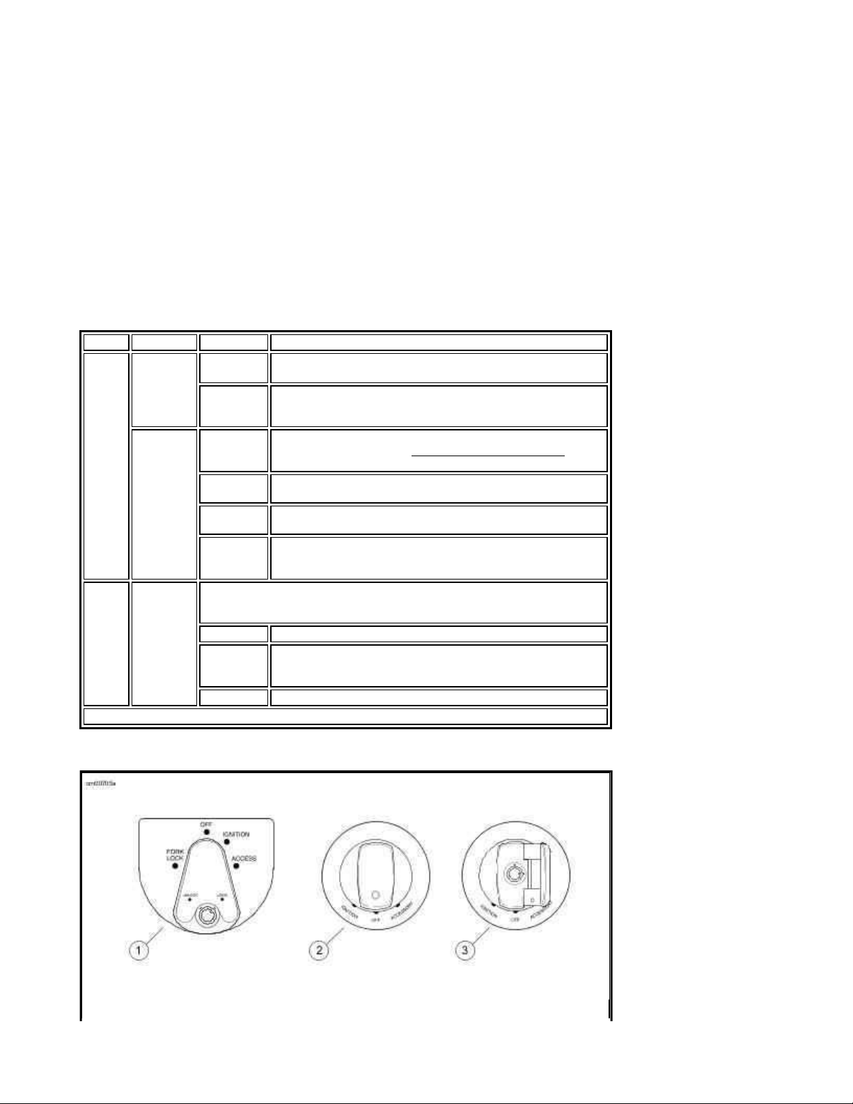
See Ignition/Headlamp Key Switch: Touring Models. The ignition/headlamp key switch controls
electrical functions of the motorcycle.
Protect your vehicle against theft. After parking your motorcycle, lock the
steering head and remove ignition key from switch. Failure to lock your
motorcycle may result in theft and/or equipment damage. (00151a)
Do not operate vehicle with forks locked. Locking the forks restricts the
vehicle's turning ability, which could result in death or serious injury. (00035a)
Page 20
Do not lubricate barrel locks with petroleum based lubricants or graphite.
Page
2
of 332008 Touring Models Owner's Manual: Controls and Indicators
8/
30/
2012
https://www.harley
-
davidson.com/en_US/Content/Pages/Owners/om/2008/en/TOURING/f
...
Inoperative locks may result. (00152a)
NOTES:
z Harley-Davidson recommends removing key from ignition/fork lock before operating
motorcycle. If you do not remove key, it can fall out during operation.
z ACCESS/ACCESSORY - Accessories and hazard warning flasher can be turned on. Instrument
lamps are on. Brake lamp and horn can be activated. Key may be removed.
z The lamps illuminate when the switch is in the IGNITION position, as required by law in some
localities.
Ignition/Headlamp Switch Positions: 2008 Touring Models
MODEL FUNCTION LABEL OPERATION
FLHT
FLHTC
FLHTCU
FLTR
FLHX
FLHR
FLHRC
* International models have an additional function. Position lamp and tail lamp are also on.
Key Lock LOCK Locks the switch in either the FORK LOCK or ACCESS switch
position. Remove the key for security.
UNLOCK Unlocks the switch. Unlocked, the switch can be rotated to any
of the 4 positions. To prevent loss when riding, remove the
key.
Switch FORK LOCK Locks fork in left position to discourage unauthorized use of
vehicle when parked. See Fork Lock: Touring Models for
operation.
OFF When switch is in OFF position, the ignition, lamps and
accessories are off.
IGNITION When the switch is in the IGNITION position, the motorcycle
can be started and all lamps and accessories will operate.
ACCESS When the switch is in the ACCESS position, all the lamps and
accessories will operate but the engine can not be started. In
ACCESS, the switch can be locked.
Switch Switch is locked or unlocked by lifting switch cover, inserting key and
turning key counterclockwise to lock, clockwise to unlock. Key may be
removed in any position.
OFF Ignition, lamps and accessories are off.
ACCESSORY Accessories are on. Hazard warning flashers can be left on.
Instrument lamps are on. Brake lamp and horn can be
activated.*
IGNITION Ignition, lamps and accessories are on.*
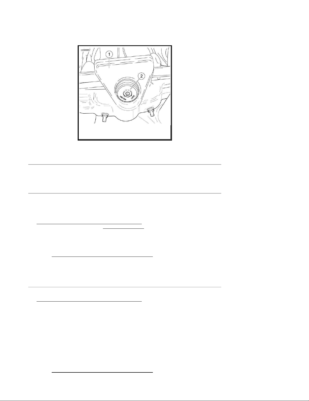
1. All except FLHR models
Page 21
2. All FLHR models (cover shown closed)
Page
3
of 332008 Touring Models Owner's Manual: Controls and Indicators
8/
30/
2012
https://www.harley
-
davidson.com/en_US/Content/Pages/Owners/om/2008/en/TOURING/f
...
3. All FLHR models (cover shown open)
Ignition/Headlamp Key Switch: Touring Models
Fork Lock: Touring Models
Protect your vehicle against theft. After parking your motorcycle, lock the
steering head and remove ignition key from switch. Failure to lock your
motorcycle may result in theft and/or equipment damage. (00151a)
Using the fork lock immediately after parking your motorcycle will discourage unauthorized use or
theft when parking your motorcycle.
See Fork Lock: FLHR/FLHRC. On FLHR/FLHRC models, the fork lock is located at the top of the
steering head, behind the headlamp nacelle and inset in the handlebar clamp shroud.
See Ignition/Headlamp Key Switch: Touring Models. On FLHT/FLTR/FLHX models, the fork lock
is integrated into the ignition switch.
NOTE:
Do not force the switch into the locked position or switch damage can occur.
Do not operate vehicle with forks locked. Locking the forks restricts the
vehicle's turning ability, which could result in death or serious injury. (00035a)
To Lock Fork on FLHR/FLHRC Models
1. Turn fork to full left position.
2. See Fork Lock: FLHR/FLHRC. Insert key and turn key counterclockwise to LOCK position.
Remove key.
3. To unlock fork, insert key and turn clockwise to UNLOCK position. Remove key.
To Lock Fork on FLHT/FLTR/FLHX Models
1. Turn fork to full left position.
2. See Ignition/Headlamp Key Switch: Touring Models. Turn switch knob to FORK LOCK
and push knob down.
3. Insert key and turn key to LOCK position. Remove key.
Page 22
4. To unlock fork, insert key and turn to UNLOCK position. Remove key and rotate switch knob
Page
4
of 332008 Touring Models Owner's Manual: Controls and Indicators
8/
30/
2012
https://www.harley
-
davidson.com/en_US/Content/Pages/Owners/om/2008/en/TOURING/f
...
out from the FORK LOCK position.
1. Clamp shroud
2. Fork lock
Fork Lock: FLHR/FLHRC
Hand Controls: Basic Operation
Electric Starter Switch
NOTE:
Off/Run switch MUST be in RUN position to operate engine.
See Basic Handlebar Controls: FLHRC Shown (typical). The electric starter switch is located on
the right handlebar control group. See Starting the Engine for detailed operation procedures.
1. Put the engine off/run switch in the RUN position and the transmission in neutral. Neutral
(green) indicator lamp should be illuminated.
2. See Ignition/Headlamp Key Switch: Touring Models. Turn ignition/headlamp key
switch to IGNITION and push the START switch to operate starter motor.
Engine OFF/RUN Switch
See Basic Handlebar Controls: FLHRC Shown (typical). The engine off/run switch (7) turns the
ignition power ON or OFF. The engine off/run switch is located on the right handlebar control. Push
the top portion of the engine off/run switch to turn off ignition power and shut the engine off. Push
the bottom portion of the engine off/run switch to turn on ignition power.
NOTES:
z The engine off/run switch must be in the RUN position to start or operate the engine.
z The engine off/run switch should be used to shut the engine off.
1. To shut the engine off, push the top of the off/run switch to the ignition OFF position.
2. See Ignition/Headlamp Key Switch: Touring Models. Turn the ignition key to the OFF
Page 23
position to turn the ignition power completely OFF.
Page
5
of 332008 Touring Models Owner's Manual: Controls and Indicators
8/
30/
2012
https://www.harley
-
davidson.com/en_US/Content/Pages/Owners/om/2008/en/TOURING/f
...
Throttle Control Grip
See Basic Handlebar Controls: FLHRC Shown (typical). The throttle control grip (9) is located
on the right handlebar control and is operated with the right hand.
To reduce rider fatigue on long trips, a spring loaded throttle friction adjustment screw (10) is
located at the bottom of the throttle grip clamp on non-cruise equipped models.
1. Slowly turn throttle control grip clockwise (toward the front of the bike) to close the throttle
(decelerate).
2. Slowly turn throttle control grip counterclockwise (toward rear of bike) to open the throttle
(accelerate).
Do not tighten throttle friction adjustment screw to the point where the engine
will not return to idle automatically. Over-tightening can lead to loss of vehicle
control, which could result in death or serious injury. (00031b)
3. Unscrew the throttle friction adjustment screw so the throttle returns to the idle position
when the hand is removed from the grip.
4. Screw the throttle adjustment screw in to increase friction on grip. This provides a damping
effect on throttle motion.
NOTE:
The throttle friction adjustment screw should not be used under normal stop and go operating
conditions.
Clutch Hand Lever
Do not position fingers between hand control lever and handlebar grip.
Improper hand positioning can impair control lever operation and cause loss of
vehicle control, which could result in death or serious injury. (00032a)
See Basic Handlebar Controls: FLHRC Shown (typical). The clutch hand lever (1) is located on
the left handlebar and is operated with the fingers of the left hand.
1. Slowly pull clutch hand lever in against handlebar grip to fully disengage clutch.
2. Shift to first gear using the gear shifter lever. See Cruise Control: Touring Models.
3. Slowly release the clutch hand lever to engage clutch.
A clutch switch is incorporated into the left handlebar switch assembly. It enables the rider to start
the vehicle in any gear (or in neutral) as long as the clutch lever is pulled in. If the clutch is not
disengaged, the vehicle will not start.
Page 24

Horn Switch
Page
6
of 332008 Touring Models Owner's Manual: Controls and Indicators
8/
30/
2012
https://www.harley
-
davidson.com/en_US/Content/Pages/Owners/om/2008/en/TOURING/f
...
See Basic Handlebar Controls: FLHRC Shown (typical). The horn is operated by pushing on the
horn switch (2) located on the left handlebar control group.
Headlamp Dimmer Switch
See Basic Handlebar Controls: FLHRC Shown (typical). The headlamp dimmer switch (3) is
located on the left handlebar. The switch has two positions to activate the headlamps high or low
beams.
z Press the top of the headlamp dimmer beam switch to activate the high beam.
z Press the bottom of the headlamp dimmer switch to return to the low beam.
See Indicator Lamps. The (blue) high beam indicator lamp will illuminate when the high beam is
on.
Turn Signal Switches
See Basic Handlebar Controls: FLHRC Shown (typical). Each handlebar control group contains
a turn signal switch.
z The right turn signal switch (11) operates the right front and right rear flashing lamps.
z The left turn signal switch (4) operates the left front and left rear flashing lamps.
NOTE:
Front turn signal lamps also function as running lamps (except International models).
Cruise Control Switches
Electronic cruise control is standard for FLHRC, FLTR, and FLHTCU models. For all other models,
cruise control is available as a factory-installed option.
See Cruise Control: Touring Models for detailed operation.
Page 25
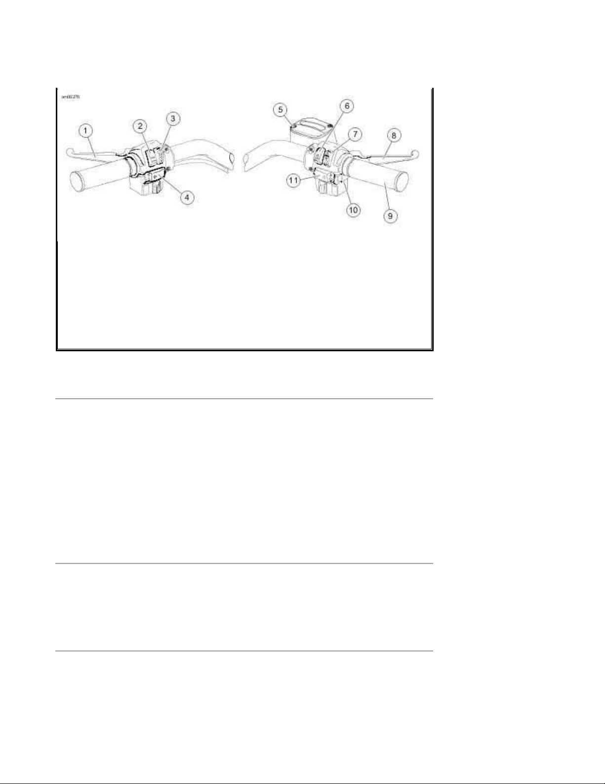
1. Clutch hand lever
Page
7
of 332008 Touring Models Owner's Manual: Controls and Indicators
8/
30/
2012
https://www.harley
-
davidson.com/en_US/Content/Pages/Owners/om/2008/en/TOURING/f
...
2. Horn switch
3. Headlamp dimmer switch
4. Left turn signal switch
5. Master cylinder reservoir
6. Electric starter switch
7. Engine off/run switch
8. Brake hand lever
9. Throttle control grip
10. Throttle friction adjusting screw (not shown, not used on cruise control models)
11. Right turn signal switch
Basic Handlebar Controls: FLHRC Shown (typical)
Electronic Throttle Control (ETC)
Touring models are equipped with Electronic Throttle Control (ETC). Instead of using a mechanical
cable connection to the throttle body, this technology uses redundant grip sensors to indicate rider
requested throttle position to the Electronic Module (ECM). The ECM then regulates proper fuel/air
intake and ignition timing based on the rider request. The grip sensor is manufactured with internal
cams and spring retainer for natural feel and operation.
ETC operation is designed for rider safety and continued motorcycle operation, even in the event of
a component failure. The Electronic Control Module monitors the status of the grip sensors, throttle
plate actuation and airflow. If any problems are detected, the motorcycle will disable cruise control,
illuminate the engine check lamp, and revert to one of the following fallback modes.
ETC Limited Performance Mode
The rider will experience near-normal operation. The motorcycle will operate with provisions to
guard against unintended acceleration.
ETC Power Management Mode
The throttle plate actuator returns to an "idle detent" or "limp-home" position, which will provide
enough torque to achieve speed of about 25 mph 40 kph . The motorcycle's response to grip sensor
input is significantly reduced.
ETC Forced Idle Mode
Page 26

The throttle plate actuator is forced to a "fast idle" position, which will provide enough torque to
Page
8
of 332008 Touring Models Owner's Manual: Controls and Indicators
8/
30/
2012
https://www.harley
-
davidson.com/en_US/Content/Pages/Owners/om/2008/en/TOURING/f
...
crawl, but not enough torque to operate at traffic speeds.
ETC Forced Shutdown Mode
The engine is forced to shut down.
Turn Signal Switch Operation
The turn signal switches are used by the turn signal module to control turn signal operation based
on vehicle speed, vehicle acceleration and turn completion.
Momentarily depress the desired turn signal switch. The turn signal lamps will begin and continue
flashing until they are manually or automatically cancelled. As long as the motorcycle is stationary,
the signals will flash.
NOTES:
z If you are signaling to turn in one direction and you depress the switch for the opposite turn
signal, the first signal is cancelled and the opposite side begins flashing.
z If you want to stop the lamps from flashing, briefly depress the turn signal switch a second
time. The turn signal lamps will stop flashing.
Hazard Warning 4-Way Flasher
Use the following method to activate the four-way flashers.
1. With the ignition key ON and security system disarmed (models with security only), press
the left and right turn signal switches at the same time.
2. Turn the ignition key OFF and arm the security system if present and desired. The four-way
flashers will continue for two hours.
3. To cancel four-way flashing, disarm the security system if necessary, turn the ignition key
ON and press the left and right turn signal switches at the same time.
This system allows a stranded vehicle to be left in the four-way flashing mode and secured until help
is found.
Indicator Lamps
See Indicator Lamps. Five indicator lamps are provided.
z The green TURN indicators will flash when turn signals are activated; therefore, flashing
indicates the chosen turn direction. When the 4-way hazard flashers are operating, both turn
indicators will flash simultaneously.
Page 27
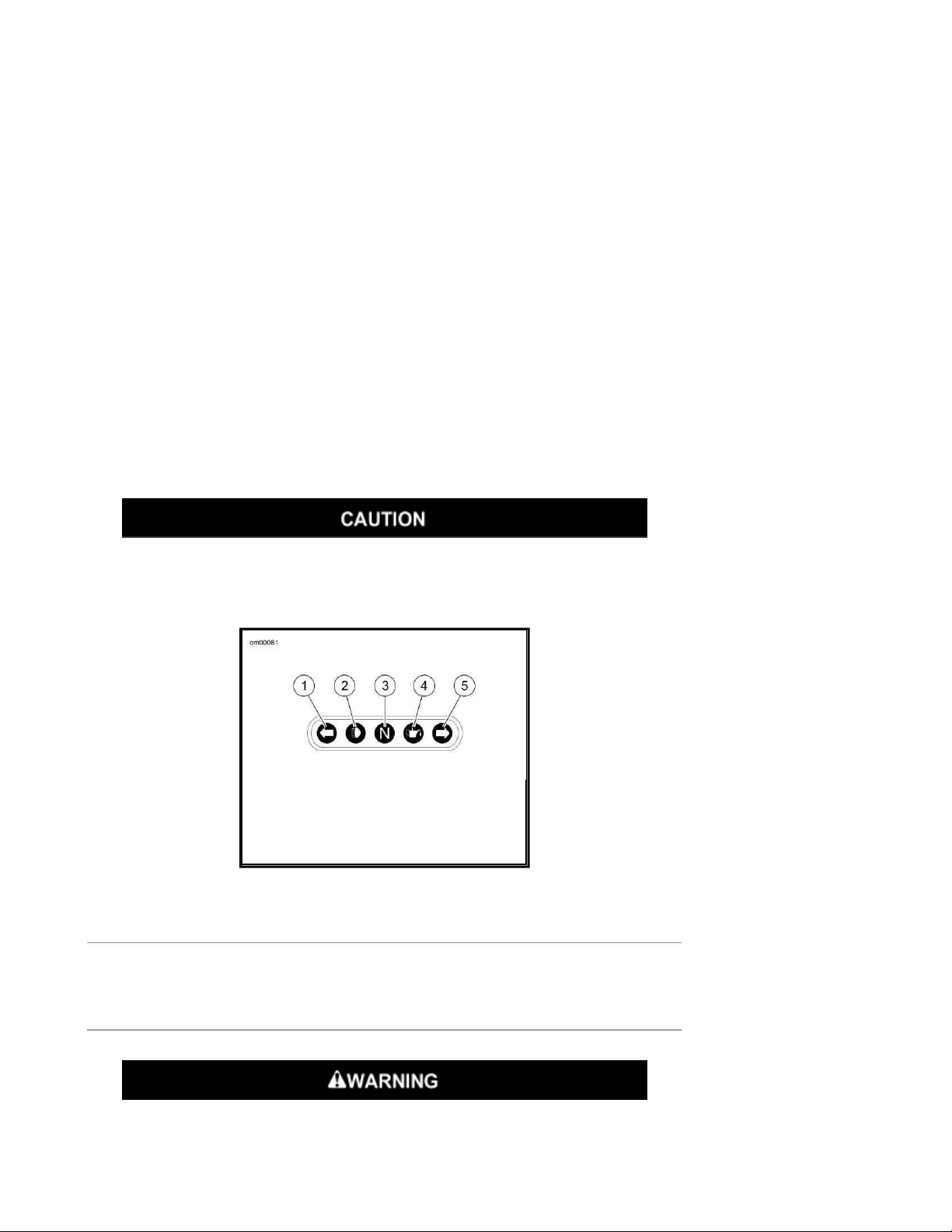
z The blue BEAM indicator lamp, when lit, signals high beam headlamp operation.
Page
9
of 332008 Touring Models Owner's Manual: Controls and Indicators
8/
30/
2012
https://www.harley
-
davidson.com/en_US/Content/Pages/Owners/om/2008/en/TOURING/f
...
z The green NEUTRAL lamp, when lit, signals the transmission is in neutral gear.
z The red OIL indicator lamp, when lit, signals that oil is not circulating through the engine.
NOTE:
The OIL indicator lamp will glow when the ignition is turned on prior to starting engine. With engine
running, lamp should be off when engine speed is above idle.
Several other circumstances that could cause the red oil indicator lamp to signal, include the
following:
z If the oil pressure indicator lamp does not go off at speeds above idling, it is usually because
of an empty oil tank or diluted oil.
z In freezing weather the oil feed may clog with ice and sludge, preventing oil circulation.
z A grounded oil signal switch wire.
z A faulty signal switch.
z A damaged or improperly installed check valve.
z Trouble with the pump.
If the oil pressure indicator lamp remains lit, always check the oil supply first.
If the oil supply is normal and the lamp is still lit, stop the engine at once and
do not ride further until the trouble is located and the necessary repairs are
made. Failure to do so may result in engine damage. (00157a)
1. Left turn
2. High beam
3. Neutral
4. Oil
5. Right turn
Indicator Lamps
Instruments: Touring Models
Speedometer
Travel at speeds appropriate for road and conditions and never travel faster
Page 28

than posted speed limit. Excessive speed can cause loss of vehicle control,
Page
10
of 332008 Touring Models Owner's Manual: Controls and Indicators
8/
30/
2012
https://www.harley
-
davidson.com/en_US/Content/Pages/Owners/om/2008/en/TOURING/f
...
which could result in death or serious injury. (00008a)
See Indicator Lamps: Touring Models. The speedometer registers miles per hour (U.S. models)
or kilometers per hour (international models) of forward speed. The speedometer also provides the
following selectable functions:
z Odometer
z Trip odometers A and B
z 12 or 24 hour clock (if radio not installed)
z Fuel range function
The speedometer has a single display window for the above functions. If an Advanced Audio System
is installed, the radio will provide the clock function.
1. See Indicator Lamps: Touring Models. Pressing the function switch with the ignition
switch in any position will activate the odometer reading and time. Time and
mileage/kilometers may be checked without unlocking ignition switch. Press and release
function switch once to view odometer. Press and release switch again to display time.
2. To check mileage on trip odometers, the ignition switch must be in the ACC or IGNITION
position. Press and release the function switch until the desired trip odometer reading is
displayed. An A or B in the upper left of the display window identifies trip odometers.
3. To reset or zero trip odometers, have desired (A or B) odometer in display window. Press
function switch and hold switch for 2-3 seconds. The trip odometer will be reset to zero.
4. Repeat the previous step if you wish to zero both trip odometers.
Setting Clock
If the motorcycle is equipped with an Advanced Audio System, see the Advanced Audio System
section in this manual to set the clock in the radio.
1. Turn the ignition switch to ACC or IGNITION.
2. See Indicator Lamps: Touring Models. Press function switch until time (hour and
minutes) is displayed. Press and hold the function switch for five seconds or until 12HR
begins to blink in the speedometer display window. Release the button.
3. Press and release the function switch once to advance to a blinking 24HR or military style
time display. Each time you press and release the button, the display will switch between
12HR and 24HR.
4. When the desired time style is displayed, press and hold the function switch for five seconds.
The display will switch to the time display with the hours blinking.
NOTE:
There is no AM or PM time setting required. So when correct hour is reached, press and hold
function switch to advance to minute setting.
5. Press and release the function switch repeatedly to advance the hours. Each time you press
and release the switch, the display will advance one hour.
6. When the correct hour is displayed, press and hold the function switch for five seconds. The
minutes display will start blinking.
Page 29
7. Press and release the function switch repeatedly to advance the minutes display. Each time
Page
11
of 332008 Touring Models Owner's Manual: Controls and Indicators
8/
30/
2012
https://www.harley
-
davidson.com/en_US/Content/Pages/Owners/om/2008/en/TOURING/f
...
you press and release the button, the display will advance one minute.
8. When the correct minutes are displayed, press and hold the function switch for five seconds.
The minutes display will stop blinking, indicating that the clock has been set.
9. Turn the ignition switch OFF.
Tachometer
See OPERATING RECOMMENDATIONS section. Do not operate the engine above
maximum safe RPM as shown under OPERATION (red zone on tachometer).
Lower the RPM by upshifting to a higher gear or reducing the amount of
throttle. Failure to lower RPM may cause equipment damage. (00159a)
See Indicator Lamps: Touring Models. The tachometer measures the engine speed in revolutions
per minute (RPM).
Tip Indicator Lamp
If tip occurs, check all controls for proper operation. Restricted control
movement can adversely affect the performance of the brakes, clutch or ability
to shift, which could result in loss of vehicle control and death or serious injury.
(00350a)
Should motorcycle be tipped over, the word "tip" will appear in the odometer window. Engine will
not start until reset. To reset, cycle ignition/headlamp key switch ON-OFF-ON.
Fuel Gauge
The fuel gauge indicates the approximate amount of fuel in the fuel tank(s) and is located to left of
the speedometer or on the left front panel of the fairing.
NOTE:
The FLHR left side fuel cap is a fuel gauge only. Do not remove.
Oil Pressure Gauge (FLHT/FLTR/FLHX)
The oil pressure gauge indicates engine oil pressure and is found on the front panel of the fairing.
Engine oil pressure will normally vary from 5 psi (34 kN/m2) at idle speed to 30-38 PSI (207-262
kN/m2) at 2000 RPM when engine is at normal operating temperature of 230° F (110° C).
Page 30
Voltmeter (FLHT/FLTR/FLHX)
Page
12
of 332008 Touring Models Owner's Manual: Controls and Indicators
8/
30/
2012
https://www.harley
-
davidson.com/en_US/Content/Pages/Owners/om/2008/en/TOURING/f
...
The voltmeter indicates electrical system voltage and is found on the front panel of the fairing. With
the engine running above 1500 RPM, the voltmeter should register 13-14.5 volts with battery at full
charge.
Air Temperature Gauge (FLHT/FLTR/FLHX)
The air temperature gauge indicates the ambient air temperature in degrees Fahrenheit. This gauge
is found on the front panel of the fairing.
Fuel Range Function
The fuel range function shows the approximate mileage available with the amount of fuel left in the
fuel tank.
1. With the ignition switch in the ACC or IGNITION position, press function switch until fuel
range function is displayed, as indicated by the letter 'r' in the left side of the odometer
display. The calculated remaining distance (miles or kilometers) to empty is displayed,
based on the amount of fuel in tank. Range can be accessed at any time using the function
switch.
2. When the low fuel warning lamp illuminates, the range feature will automatically be
displayed in the odometer unless this automatic pop-up feature is disabled by a press and
hold of the function switch while in range display mode. Automatic range pop-up feature will
show that it is disabled by blinking twice. Likewise, automatic range pop-up can be
reactivated by a press and hold of the function switch. Range will blink once when the
automatic pop-up feature is reenabled.
NOTE:
When the low fuel warning lamp turns on, there is approximately 1 gallon 3.8 liters of fuel
remaining in the tank. Refuel as soon as possible.
3. After the range calculation reaches 10 miles 16 kilometers remaining, the range display will
show "r Lo" to indicate that the vehicle will shortly run out of fuel.
4. The range display is only updated when the vehicle is moving 10 mph 16 km/h or greater.
Page 31

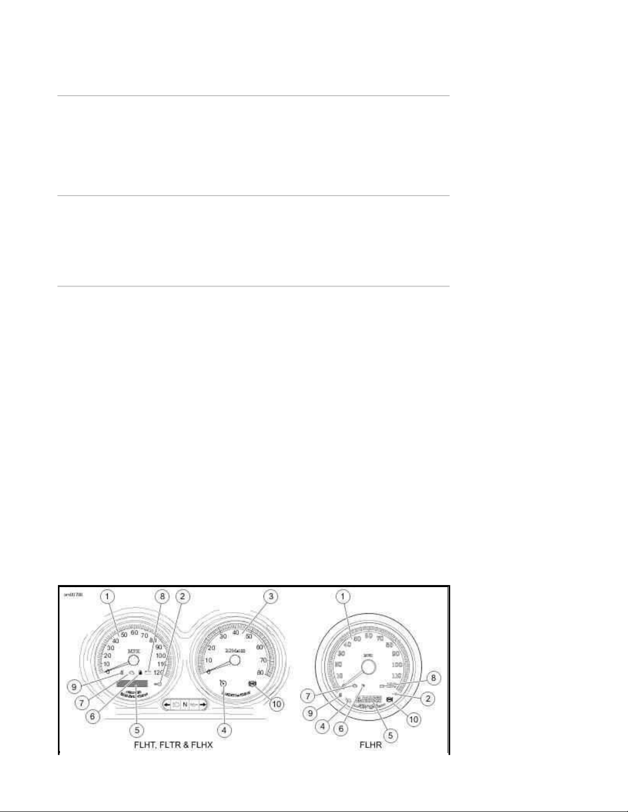
1. Speedometer
Page
13
of 332008 Touring Models Owner's Manual: Controls and Indicators
8/
30/
2012
https://www.harley
-
davidson.com/en_US/Content/Pages/Owners/om/2008/en/TOURING/f
...
2. Security system lamp
3. Tachometer
4. Cruise lamp
5. Odometer/trip-odometer/clock
6. Low fuel warning lamp
7. Engine check lamp
8. Battery discharge lamp
9. Sixth gear lamp
10. ABS lamp
Indicator Lamps: Touring Models
Indicator Lamps: Touring Models
Engine Check Lamp
See Indicator Lamps: Touring Models. The engine check lamp is located near the lower left side
of the speedometer (FLHT models) face or lower center of the speedometer (FLHR models) face. Its
purpose is to indicate whether or not the engine/engine management system is operating normally.
The engine lamp color is amber.
The engine lamp normally comes on when the bike's ignition is first turned on and remains on for
approximately 4 seconds, as the engine management system runs a series of self-diagnostics.
If the engine lamp comes on at any other time, see a Harley-Davidson dealer.
Low Fuel Lamp
See Indicator Lamps: Touring Models. The low fuel lamp is located in the speedometer face,
lower center by check engine lamp. The low fuel lamp illuminates to indicate that you have
approximately 1 gallon 3.8 liters of gasoline left in the tank. The low fuel lamp color is amber.
Cruise Control Equipped Models
See Indicator Lamps: Touring Models. Cruise control equipped models feature two additional
indicator lamps.
z An orange lamp on the cruise control switch which indicates the cruise control is ON or OFF.
z A green lamp on the tachometer (speedometer for FLHR models) face indicates the cruise
control is SET or NOT SET.
NOTE:
Touring Models are either equipped with cruise control or are cruise control ready. See a HarleyDavidson dealer for more information.
ABS Lamp
Page 32

See Indicator Lamps: Touring Models. On ABS equipped models, the amber ABS indicator lamp
Page
14
of 332008 Touring Models Owner's Manual: Controls and Indicators
8/
30/
2012
https://www.harley
-
davidson.com/en_US/Content/Pages/Owners/om/2008/en/TOURING/f
...
begins to flash at key ON to indicate that the system is operational. It continues to flash until
motorcycle speed exceeds 3 mph 5 km/h . Continuous illumination of the lamp will only occur when
ABS detects that the system is malfunctioning. In the diagnostic mode, the lamp will also illuminate
to indicate the presence of diagnostic trouble codes (DTCs). See a Harley-Davidson dealer for
service.
If ABS lamp remains on continuously, the ABS is not operating. The standard
brake system is operational, but wheel lock up can occur. Contact a HarleyDavidson Dealer to have ABS repaired. A locked wheel will skid and can cause
loss of vehicle control, which could result in death or serious injury. (00361a)
Cruise Control: Touring Models
Operating Controls
The cruise control system provides automatic vehicle speed control.
Do not use the cruise control system in heavy traffic, on roads with sharp or
blind curves or on slippery roads of any kind. Using the cruise control in these
circumstances can cause loss of control, which could result in death or serious
injury. (00083a)
See Cruise Control Fairing Cap Switch. A fairing cap cruise control switch located to the right of
the ignition/headlamp key switch turns the cruise control system ON and OFF.
On FLHR models, the cruise control switch housing is on the left handlebar.
NOTE:
The cruise control icon on the speedometer or tachometer will turn orange to indicate the cruise
control is ON. If the orange icon does NOT come on, the system is NOT ON. You cannot SET cruise
speed, see your dealer.
See RESUME/SET Switch. RESUME/SET switch located in the right handlebar control group.
The RESUME/SET switch controls several system functions, including set, resume, accelerate and
decelerate.
Page 33

Cruise Control Fairing Cap Switch
Page
15
of 332008 Touring Models Owner's Manual: Controls and Indicators
8/
30/
2012
https://www.harley
-
davidson.com/en_US/Content/Pages/Owners/om/2008/en/TOURING/f
...
RESUME/SET Switch
Cruise Control Operation
Theory of Operation
The cruise control is designed to be safely operated with minimum movement by the rider and all
rider control actions are natural and easy.
NOTES:
z The rider always over-rides and controls the system.
z The system will not work at vehicle speeds below 30 mph 48 km/h or above 85 mph 137
km/h .
z The system is managed by the ECM. The tachometer provides information to disengage the
system if the engine RPM suddenly increases.
z Besides the ECM, the system has other components: a stepper-motor (controlled by the
computer) which operates the throttle during CRUISE operation, and several internal
switches, all sending information to the computer.
z The system will allow rider to increase speed 10 mph 16 km/h or more (depending on how
hard the rider rolls on the throttle and the condition of the bike) over the SET point before
Page 34

deactivating. This feature allows the rider to momentarily increase speed, if necessary.
Page
16
of 332008 Touring Models Owner's Manual: Controls and Indicators
8/
30/
2012
https://www.harley
-
davidson.com/en_US/Content/Pages/Owners/om/2008/en/TOURING/f
...
Rolling on the throttle to greatly increase speed may deactivate the system.
Engaging Cruise Control
1. See Indicator Lamps: Touring Models. Turn the cruise control switch to the ON position.
The orange icon on the cruise gauge face will light when activated.
2. With the motorcycle traveling at the desired cruise speed of 30-85 mph 48-137 km/h ,
momentarily push the RESUME/SET switch on the right handlebar to SET. After a delay of
about 1-1/2 seconds, the icon will turn green on the face of the gauge to indicate the
selected cruising speed is locked in.
Disengaging Cruise Control
The cruise control automatically disengages whenever the cruise control module receives one of the
following inputs:
1. Front and/or rear brake is applied.
2. Throttle is rolled back or closed, thereby actuating roll-off (disengage) switch.
3. Motorcycle clutch is disengaged (module senses too great an increase in RPM).
4. Vehicle speed is out of the operating range.
NOTE:
Rolling on the throttle more than 10 mph 16 km/h above the set speed may also deactivate the
cruise control.
When the cruise is disengaged, the green cruise engaged icon on the face of the gauge changes to
orange. The orange cruise control system icon remains ON until the main switch is turned off.
However, should you decide to SET a cruise speed, RESUME last set speed, ACCELERATE or
DECELERATE, simply press the RESUME/SET switch.
Resuming Cruise Speed
If the system is deactivated using one of the methods described under DEACTIVATING CRUISE
CONTROL, the system is still ON should you decide to RESUME the set speed. To accomplish this,
simply press the RESUME/SET switch to RESUME.
NOTE:
The computer will hold the SET speed in memory for the RESUME function. If the vehicle speed
drops more than 15 mph 24 km/h below the SET speed, speed can no longer be RESUMED. If cruise
operation is still desired, press the RESUME/SET switch to SET to reset the cruise speed.
Accelerating Above Cruise Speed
Page 35

1. With the cruise speed set, momentarily press the RESUME/SET switch to RESUME to
Page
17
of 332008 Touring Models Owner's Manual: Controls and Indicators
8/
30/
2012
https://www.harley
-
davidson.com/en_US/Content/Pages/Owners/om/2008/en/TOURING/f
...
increase the speed by 1 mph 1.6 km/h .
2. Pressing and holding the RESUME/SET switch at RESUME will cause the system to continue
to increase speed in increments of approximately 1 mph 1.6 km/h until the switch is
released. There is a delay of about 2 seconds before the speed increases.
Decelerating Cruise Control
1. With the cruise speed set, momentarily press the RESUME/SET switch to SET to reduce the
speed by 1 mph 1.6 kph .
2. Pressing and holding the RESUME/SET switch at SET will cause the system to continue to
reduce speed in increments of approximately 1 mph 1.6 kph until the switch is released.
There is a delay of about 2 seconds before the speed decreases.
Deactivating Cruise Control
Turn cruise control switch to the OFF position. The orange icon in the gauge is extinguished to
indicate the system is OFF.
NOTES:
System will NOT work if:
z Rider operates bike at vehicle speeds below 30 mph 48 km/h or above 85 mph 137 km/h .
z Brake lamps are on constantly. See dealer.
Gear Shift Lever: Touring Models
Location
The clutch must be fully disengaged before attempting a gear shift. Failure to
fully disengage the clutch can result in equipment damage. (00182a)
The gear shift lever is located on the left side of the motorcycle and is operated with the left foot.
The gear shift lever shifts the six-speed transmission from one gear to the next.
Shift Pattern
See Shift Pattern: 6-Speed Touring Models. The shift pattern is sequential with first gear down
and five gears up.
Page 36

The transmission is shifted into first gear from neutral by pressing the shift lever down until it clicks
Page
18
of 332008 Touring Models Owner's Manual: Controls and Indicators
8/
30/
2012
https://www.harley
-
davidson.com/en_US/Content/Pages/Owners/om/2008/en/TOURING/f
...
into gear.
Neutral is located between first and second gear. The green neutral indicator lamp on the dash will
illuminate when the transmission is in neutral.
To shift from first gear to neutral, lift the gear shift lever 1/2 of its full stroke.
To upshift to the next higher gear, lift the gear shift lever up until it clicks into gear.
To downshift to the next lower gear, press the gear shift lever down until it clicks into gear.
NOTES:
Release the foot shift lever after each gear change. This allows the lever to return to its central
position before another gear change can be made.
Heel-Toe Foot Shifter
See Shift Pattern: 6-Speed Touring Models. Touring Models are fitted with a heel-toe shifter
lever. Two shift levers are fitted to the shifter shaft - one facing forward and one rearward.
The toe of the left foot can upshift or downshift using the front shift lever. However, the rider has
the option of upshifting with the heel on the rear facing shift lever.
Shift Pattern: 6-Speed Touring Models
Shifting While Stopped
When difficulty of shifting gears is experienced, do not under any
circumstances, attempt to force the shift. The results of such abuse will be a
damaged or broken shifter mechanism. (00161a)
When the motorcycle is standing still in first gear with the engine off or in neutral with the engine
Page 37

running, the transmission may not shift gears. Because the rear wheel and drive belt are not
Page
19
of 332008 Touring Models Owner's Manual: Controls and Indicators
8/
30/
2012
https://www.harley
-
davidson.com/en_US/Content/Pages/Owners/om/2008/en/TOURING/f
...
turning, the transmission gear teeth and engagement dogs can not line up.
To get one gear to disengage and the next gear to engage, pull the clutch lever in and move the
motorcycle backward and forward while maintaining slight pressure on the shift lever.
See Shifting Gears for more information.
Brake System
General
The rear brake pedal controls the rear wheel brake and is located on the motorcycle's right side.
Operate the rear brake pedal with the right foot.
The front brake hand lever controls the front wheel brake and is located on the right handlebar.
Operate the hand lever with the fingers of the right hand.
Do not position fingers between hand control lever and handlebar grip.
Improper hand positioning can impair control lever operation and cause loss of
vehicle control, which could result in death or serious injury. (00032a)
Some models are equipped with an anti-lock braking system.
Non-ABS Brake System
Apply brakes uniformly and evenly to prevent wheels from locking. Use front and rear brakes equally
for best results.
Do not apply brake strongly enough to lock the wheel. A locked wheel will skid
and can cause loss of vehicle control, which could result in death or serious
injury. (00053a)
Anti-lock Brake System (ABS)
Harley-Davidson's Anti-Lock Brake System assists the rider in maintaining control when braking in a
straight-line emergency situation. ABS operates independently on front and rear brakes to keep the
wheels rolling and prevent uncontrolled wheel lock-ups either on dry pavement or on slick surfaces
such as gravel, leaves or when riding in wet conditions.
ABS: How It Works
Page 38

The ABS monitors sensors at the front and rear wheels to determine wheel speed. If the system
Page
20
of 332008 Touring Models Owner's Manual: Controls and Indicators
8/
30/
2012
https://www.harley
-
davidson.com/en_US/Content/Pages/Owners/om/2008/en/TOURING/f
...
detects one or both wheels are slowing down too quickly, which indicates they are close to locking,
or if the deceleration rate does not match a criteria stored in memory, the ABS reacts. The system
rapidly opens and closes valves to modulate the brake pressure being applied by the rider. During
ABS activation, the system provides the electronic equivalent of manually pumping the brakes and is
capable of cycling up to seven times per second.
The rider will recognize ABS activation by the slight pulsing sensation in the hand lever or the rear
brake pedal. The pulsing sensation may also be accompanied by a clicking sound from the ABS
module. Both are the result of normal operation. Refer to ABS Symptoms and Conditions.
ABS: How To Use
While an advantage in emergency braking, ABS is not a substitute for safe riding. The safest way to
stop a motorcycle is upright with both wheels straight.
Harley-Davidson ABS is a manual assist system. When in an emergency stopping situation, maintain
pressure on the brakes through all ABS events. Do not modulate or "pump" the brake controls. The
wheels won't lock until the end of the stop when motorcycle speed reaches approximately four miles
per hour and ABS is no longer needed.
ABS cannot prevent lockup of rear wheel due to engine braking. ABS will not
aid in cornering or on loose/uneven surfaces. A locked wheel will skid and can
cause loss of vehicle control, which could result in death or serious injury.
(00362a)
More information is available at www.harley-davidson.com/abs.
ABS: Tires and Wheels
ABS motorcycles must always use tires and wheels that are the same as the original equipment. The
ABS monitors the rotational speed of the wheels through individual wheel speed sensors. Changing
to different diameter wheels or different sized tires can alter the rotational speed. This can upset the
calibration of the ABS and have an adverse effect on its ability to detect and prevent uncontrolled
wheel lockups. Tire inflation pressure that is significantly low also can have an adverse effect.
ABS Symptoms and Conditions
SYMPTOM CONDITION
Pulsing brake lever
or pedal during an
ABS event
Clicking sound
during an ABS
event
ABS lamp flashing Normal condition - key turned to IGNITION - speed under 3 mph 5 km/h .
Perceived "surge"
while braking
Normal condition.
Normal condition.
Normal condition - noticeable when braking with one brake (front only or
rear only). Result of a reduction in deceleration which can be caused by
cracks or bumps in road, engine braking (high engine RPMs causing the rear
wheel to slow down), hard braking at slow speeds, and other conditions.
Page 39

Temporarily stiff
Page
21
of 332008 Touring Models Owner's Manual: Controls and Indicators
8/
30/
2012
https://www.harley
-
davidson.com/en_US/Content/Pages/Owners/om/2008/en/TOURING/f
...
rear brake pedal
Tire chirp Normal condition - depending on surface, tire can chirp without locking the
Black mark on
pavement
Wheel lock at low
speed
Normal condition - engine braking (high engine RPMs causing the rear wheel
to slow down) or down shifting can activate ABS. If applying the rear brake
at the same time or immediately after, the ABS may be closing a valve to
prevent pressure to the rear brake.
wheel.
Normal condition - depending on surface, tire can leave a black mark
without locking the wheel.
Normal condition - ABS will not activate on front wheel below 3 mph 5 km/h
or on rear wheel below 5 mph 8 km/h .
Jiffy Stand
Always park motorcycle on a level, firm surface. An unbalanced motorcycle can
fall over, which could result in death or serious injury. (00039a)
The jiffy stand is located on the left side of the motorcycle and swings outward to support the
motorcycle for parking.
The jiffy stand locks when placed in the full forward (down) position with
vehicle weight on it. If the jiffy stand is not in the full forward (down) position
with vehicle weight on it, the vehicle can fall over which could result in death
or serious injury. (00006a)
Be sure jiffy stand is fully retracted before riding. If jiffy stand is not fully
retracted, it can contact the road surface causing a loss of vehicle control,
which could result in death or serious injury. (00007a)
Jiffy Stand Interlock: International Models
International models are equipped with a jiffy stand interlock feature.
If the rider attempts to start the engine or pushes the starter button while the transmission is in
gear and the jiffy stand is down, then the jiffy stand interlock system will not permit the engine to
run. The message "SidE StAnd" will scroll across the odometer to indicate this to the rider. Raising
the jiffy stand (or putting the transmission in neutral) will permit the engine to run and clear the
message.
If the jiffy stand falls out of the fully retracted position while riding at speeds greater than 10 mph
15 kph , then the jiffy stand interlock system will maintain engine operation and alert the rider
about this by illuminating the indicators (flash twice) and scroll the message "SidE StAnd" across the
odometer. The message will remain until the system detects the jiffy stand in the fully retracted
position again. The rider may continue to operate the vehicle while in this mode.
Page 40

The rider may clear the text messages at any time by pressing the function switch once while the
Page
22
of 332008 Touring Models Owner's Manual: Controls and Indicators
8/
30/
2012
https://www.harley
-
davidson.com/en_US/Content/Pages/Owners/om/2008/en/TOURING/f
...
vehicle is powered up.
NOTE:
If the operation of raising the jiffy stand and putting the transmission in gear is rapidly executed,
the jiffy stand bouncing off the frame could cause the jiffy stand interlock system to activate and
stop the engine.
Rear View Mirrors
Objects in mirrors are closer than they appear. Use caution when judging
distance of objects in mirrors. Failure to judge correct distances could result in
death or serious injury. (00033a)
Your vehicle is equipped with two convex rear view mirrors.
This type of mirror is designed to give a much wider view to the rear than a flat mirror. However,
cars and other objects seen in this type of mirror will look smaller and farther away than they
actually are.
z Use caution when judging the size or relative distance of objects seen in rear view mirrors.
z Always adjust the rear view mirrors to clearly reflect the area behind the motorcycle before
riding.
NOTE:
Adjust mirrors so you can see a small portion of your shoulders in each mirror. This will help you
establish the relative distance of vehicles to the rear of your motorcycle.
Fuel Filler Cap: Touring Models
To open, turn fuel filler cap counterclockwise and lift up. To close, turn fuel filler cap clockwise until
it clicks. The ratchet action of the cap prevents overtightening.
Remove the fuel filler cap slowly. Fill fuel tank slowly to prevent fuel spillage. Do not fill above the
bottom of the filler neck insert. Leave enough air space to allow for fuel expansion. Expansion can
cause an overfilled tank to overflow fuel through the filler cap vent onto surrounding areas. After
refueling, be sure filler cap is securely tightened. Gasoline is extremely flammable and highly
explosive. Inadequate safety precautions could result in death or serious injury.
NOTES:
z FLHT/FLTR model fuel filler cap is located beneath a door and have a ratchet action. The fuel
filler cap should be fully closed before closing the fuel door.
z Fuel filler cap turns approximately a 3/4 turn before it starts unscrewing.
z See Fuel Tank: FLHR. FLHR model fuel filler cap is located on the right side of the fuel
tank. The cap on the left side is the fuel gauge and is not removable.
See SAFE OPERATING RULES and review safety procedures listed below.
Page 41

1. Fuel gauge
Page
23
of 332008 Touring Models Owner's Manual: Controls and Indicators
8/
30/
2012
https://www.harley
-
davidson.com/en_US/Content/Pages/Owners/om/2008/en/TOURING/f
...
2. Fuel filler cap
3. Function switch
Do not spill fuel onto the motorcycle while refueling. Immediately wipe up fuel
spills on your motorcycle. Fuel can cause damage to cosmetic surfaces.
(00147b)
Use only unleaded fuel in catalytic converter-equipped motorcycles. Using
leaded fuel will damage the emission control system. (00150b)
Do not store motorcycle with gasoline in tank within the home or garage where
open flames, pilot lights, sparks or electric motors are present. Gasoline is
extremely flammable and highly explosive, which could result in death or
serious injury. (00003a)
Fuel Tank: FLHR
Avoid spills. Slowly remove filler cap. Do not fill above bottom of filler neck
insert, leaving air space for fuel expansion. Secure filler cap after refueling.
Gasoline is extremely flammable and highly explosive, which could result in
death or serious injury. (00028a)
Do not use aftermarket fuel caps. Aftermarket fuel caps may fit improperly and
leak, which could lead to death or serious injury. See a Harley-Davidson dealer
for approved fuel caps. (00034a)
Rear Air Suspension
Page 42

General
Page
24
of 332008 Touring Models Owner's Manual: Controls and Indicators
8/
30/
2012
https://www.harley
-
davidson.com/en_US/Content/Pages/Owners/om/2008/en/TOURING/f
...
See Rear Air Suspension Air Valve. All models feature air-adjustable rear suspension. Air
pressure in the rear shocks may be adjusted to suit load requirements, riding style and personal
comfort.
z For FLHR/C, FLHT/C/U and FLTR models with standard shocks, refer to Standard Rear
Suspension Recommended Air Pressure: FLHR/C, FLHT/C/U and FLTR.
z For FLHX models with low profile shocks, refer to Low Profile Rear Suspension
Recommended Air Pressures: FLHX.
NOTE:
These are recommended starting points. Adjust to suit load conditions, riding style and comfort
desired. Less initial pressure does not necessarily result in a softer ride. Using pressures outside the
recommended loading range will result in a reduction of available suspension travel and reduced
rider comfort.
Standard Rear Suspension Recommended Air Pressure: FLHR/C, FLHT/C/U and FLTR
SHOCK LOAD TOTAL WEIGHT PRESSURE
LB. KG PSI kPa
Solo rider up to 150 0-68 0 0
Solo rider 150-200 68-91 0-10 0-69
Solo rider 200-250 91-113 5-15 35-103
Rider with passenger weight of up to 150 0-68 10-15 69-103
Rider with passenger weight of up to 200 0-91 20-25 138-172
Maximum GVWR see label 20-35 138-241
Low Profile Rear Suspension Recommended Air Pressures: FLHX
SHOCK LOAD TOTAL WEIGHT PRESSURE
LB. KG PSI kPa
Solo rider up to 160 0-73 0-5 0-35
Solo rider 160-200 73-91 0-10 0-69
Solo rider over 200 91 5-10 35-69
Rider with passenger weight of up to 150 0-68 20-30 138-207
Rider with passenger weight of over 150 over 68 25-35 172-241
Maximum GVWR see label 40-50 276-345
Adjusting Shock Pressure
See Rear Air Suspension Air Valve. To adjust the rear shock air pressure, use an air pump to fill
or release air from the air valve located just below the frame cover on the left side of the vehicle.
Page 43

Do not exceed maximum air pressure for rear suspension. Air components fill
Page
25
of 332008 Touring Models Owner's Manual: Controls and Indicators
8/
30/
2012
https://www.harley
-
davidson.com/en_US/Content/Pages/Owners/om/2008/en/TOURING/f
...
rapidly. Therefore, use low air line pressure. Failure to do so may result in
possible damage to components. (00165a)
NOTE:
An AIR SUSPENSION PUMP AND GAUGE HD-34633 is available at your Harley-Davidson dealer.
Use caution when bleeding air from the suspension. Moisture combined with
lubricant may leak onto the rear wheel, tire and/or brake components and
adversely affect traction, which could result in death or serious injury.
(00084a)
NOTES:
z Do not exceed max GVWR or GAWR.
z ON FLHX MODELS: Always clear the line by adding 3-5 psi 21-35 kPa before releasing air
from the pump's valve, but do not exceed 50 psi 345 kPa .
z ON ALL BUT FLHX MOD ELS: Always clear the line by adding 3-5 psi 21-35 kPa before
releasing air from the pump's valve, but do not exceed 35 psi 241 kPa .
Rear Air Suspension Air Valve
Luggage
Do not exceed the motorcycle's Gross Vehicle Weight Rating (GVWR) or Gross
Axle Weight Rating (GAWR). Exceeding these weight ratings can affect stability
and handling, which could result in death or serious injury. (00016e)
GVWR is the sum of the weight of the motorcycle, accessories, and the maximum weight of the
rider, passenger and cargo that can be safely carried.
Page 44

GAWR is the maximum amount of weight that can be safely carried on each axle.
Page
26
of 332008 Touring Models Owner's Manual: Controls and Indicators
8/
30/
2012
https://www.harley
-
davidson.com/en_US/Content/Pages/Owners/om/2008/en/TOURING/f
...
The GVWR and GAWR is shown on the information plate, located on the frame steering head.
Tour-Pak
Operation
See Tour-Pak Lock and Draw Catch. Unlock lock and open draw catches.
Removal/Installation
Do NOT pull on any electrical wires. Pulling on electrical wires may damage the
internal conductor causing high resistance, which may result in minor or
moderate injury. (00168a)
The Tour-Pak can be located in two positions. See the service manual or a Harley-Davidson dealer
about Tour-Pak removal/relocation.
1. Key
2. Lock
3. Draw catch
Tour-Pak Lock and Draw Catch
Saddlebags: FLHR/FLHT/FLHX/FLTR
Opening
Page 45

1. See Saddlebags: FLHT/FLTR. Unlock latch.
Page
27
of 332008 Touring Models Owner's Manual: Controls and Indicators
8/
30/
2012
https://www.harley
-
davidson.com/en_US/Content/Pages/Owners/om/2008/en/TOURING/f
...
2. Place fingers under latch and lift.
3. Place one hand at OUTSIDE CORNER of cover and other hand at opposite outside corner.
4. Lift outside edge of cover, pivoting inside edge of cover in brackets.
5. Lift inside edge of cover to disengage brackets.
6. Bring cover towards you, over saddlebag.
7. As you bring cover toward you, let it flip over, so the inside faces up. Let cover rest against
rub bars and nylon check strap.
NOTE:
The saddlebag lids are designed to stay attached to the bags at all times.
Closing
1. See Saddlebags: FLHT/FLTR. Use both hands to hold OUTSIDE corners of cover up and
slide inside edge back into place so brackets slide together.
2. Close lid and secure latch. Brackets will engage automatically.
NOTE:
Saddlebag latch and Tour-Pak draw catches should be closed and locked whenever motorcycle is in
operation.
Removing
See Bail Head Studs. The saddlebags are secured to the support brackets by 1/4 turn fasteners
called bail head studs.
NOTE:
If your vehicle (international only) does not have the wire form "bail", use a flat bladed screwdriver
to turn the studs.
1. Unscrew saddlebag fasteners by turning 1/4 turn counterclockwise.
2. Remove saddlebag.
Installing
Carefully place saddlebag in position on saddlebag rail and align the bail head studs with the support
bracket fasteners.
1. See Bail Head Studs. Fasten studs by pushing into support bracket fasteners and turning
Page 46

1/4 turn clockwise.
Page
28
of 332008 Touring Models Owner's Manual: Controls and Indicators
8/
30/
2012
https://www.harley
-
davidson.com/en_US/Content/Pages/Owners/om/2008/en/TOURING/f
...
2. Check that studs are securely fastened.
Adjustments
If the latches become loose, you can adjust the latch fingers.
Adjust the latch fingers only enough to enable them to properly engage the
latch hinge. Bending latch fingers back and forth can overstress the metal and
weaken the fingers. (00169a)
1. Bend the fingers until they firmly engage the hinge.
2. See Miscellaneous Lubrication for lubrication details.
1. Hinge
2. Latch
Saddlebags: FLHT/FLTR
1. Anchor tabs
2. Bail head studs
3. Anchor brackets
Bail Head Studs
Page 47

Saddlebags: FLHRC
Page
29
of 332008 Touring Models Owner's Manual: Controls and Indicators
8/
30/
2012
https://www.harley
-
davidson.com/en_US/Content/Pages/Owners/om/2008/en/TOURING/f
...
Opening
See Saddlebag Quick Disconnect. To use the quick disconnect strap feature, lift up the strap end
to expose the quick release buckle and press on the lock tabs as shown.
The straps may also be opened and closed using the buckle in a conventional manner.
Closing
Insert the male strap end into the receptacle on the bag and push until a positive "click" is felt.
NOTE:
See Leather Care for proper saddlebag care.
Saddlebag Quick Disconnect
Windshield: FLHR/C
Removal
1. See Windshield: FLHR/C. Insert your fingers into the wire form latch springs at either side
of the windshield and move the TOP of the windshield assembly forward, until the TOP
bracket notches slide away from the grommets.
2. Carefully lift the windshield bracket BOTTOM notches off the bottom grommets.
3. Remove windshield.
NOTE:
Page 48

For proper windshield maintenance, see Windsh ields.
Page
30
of 332008 Touring Models Owner's Manual: Controls and Indicators
8/
30/
2012
https://www.harley
-
davidson.com/en_US/Content/Pages/Owners/om/2008/en/TOURING/f
...
Installation
1. See Windshield: FLHR/C. Insert your fingers into the wire form latch springs at either side
of the windshield and slide the BOTTOM windshield bracket notches onto the bottom
grommets.
2. Slide the TOP bracket notches onto the top grommets.
1. Wire form latch spring
2. Grommet
3. Windshield
4. Clutch cable
Windshield: FLHR/C
Adjustable Air Deflectors: FLHTCU
See Adjustable Air Deflector: FLHTCU Models. Air deflectors, located along the left and right
bottom edge of fairing, may be adjusted to direct airflow for rider and passenger comfort.
To adjust, grasp the outer edge of the deflector and pivot to desired position.
Adjustable Air Deflector: FLHTCU Models
Cigarette Lighter: FLHX, FLHT/C/U, FLTR
Page 49

See Cigarette Lighter. FLHX, FLHT/C/U and FLTR models are equipped with a cigarette lighter. The
Page
31
of 332008 Touring Models Owner's Manual: Controls and Indicators
8/
30/
2012
https://www.harley
-
davidson.com/en_US/Content/Pages/Owners/om/2008/en/TOURING/f
...
lighter is located on the left side of the fairing. To operate, press lighter into socket. The lighter will
pop out when hot.
The lighter is not intended to be used as a power port for electrical devices. Damage to the lighter
receptacle may occur.
Cigarette Lighter
Accessory Switch
See Switch Indicators. All touring models have an accessory switch (4) for the owner's use. This
switch is located on the right side of the fairing (FLHT) or left side triple clamp shroud (FLHR).
See Accessory Connector. There is an accessory connector located in front of the battery that can
be activated with the ACC switch. See a Harley-Davidson dealer for possible uses.
It is possible to overload your motorcycle's charging system by adding too
many electrical accessories. If your combined electrical accessories operating
at any one time consume more electrical current than your vehicle's charging
system can produce, the electrical consumption can discharge the battery and
cause vehicle electrical system damage. See a Harley-Davidson dealer for
advice about the amount of current consumed by additional electrical
accessories, or for necessary wiring changes. (00211b)
Page 50

1. Auxiliary (SPOT)
Accessory Connector
Page
32
of 332008 Touring Models Owner's Manual: Controls and Indicators
8/
30/
2012
https://www.harley
-
davidson.com/en_US/Content/Pages/Owners/om/2008/en/TOURING/f
...
2. Speakers
3. Cruise control
4. ACC switch (ACCESSORY)
Switch Indicators
Accessory Connector
Auxiliary Lamps: FLHT and FLHR/C
See Switch Indicators. Use the auxiliary lamp switch (1) to turn ON the auxiliary lamps as
required.
NOTES:
z On the FLHT/C/CU, the auxiliary lamp switch (SPOT) is on the left side of the
ignition/headlamp key switch on fairing cap.
z On the FLHR/C the auxiliary lamp switch (SPOT) is on the right side of the triple clamp
shroud.
z The auxiliary lamps (SPOT) do not work when the headlamp is on high beam.
Fairing Lower Vents: FLHTCU
See Fairing Lower Vent Control. Vents in fairing lowers are controlled by the lever shown. Adjust
vent openings to control air flow.
Page 51

Fairing Lower Vent Control
Page
33
of 332008 Touring Models Owner's Manual: Controls and Indicators
8/
30/
2012
https://www.harley
-
davidson.com/en_US/Content/Pages/Owners/om/2008/en/TOURING/f
...
Rider Footboards
Rider footboards are adjustable. See a Harley-Davidson dealer for adjustment.
Passenger Footboards/Footrests
Passenger footboards/footrests can be adjusted to one of three positions. Before moving to a new
position, remove plastic plugs from holes in rear swingarm brackets as necessary.
1. See Passenger Footboards: All Except FLHX Remove socket screw with lockwasher to
remove footboard/footrest bracket from rear swingarm bracket.
2. Insert pin on footboard bracket into hole in swingarm bracket at position required.
3. Install socket screw with lockwasher. Tighten socket screw to 15-18 ft-lbs (20-24 Nm).
Passenger Footboards: All Except FLHX
Page 52

Advanced Audio System
Page
1
of 292008 Touring Models Owner's Manual: Advanced Audio System
8/
30/
2012
https://www.harley
-
davidson.com/en_US/Content/Pages/Owners/om/2008/en/TOURING/f
...
Advanced Audio System
The Advanced Audio System by Harman/Kardon®is based on an electronic unit mounted inside the
front fairing of selected Harley-Davidson Touring models.
For FLHX, FLHTC, and FLTR: The Advanced Audio System is a multi-band radio receiver that
includes a Compact Disc (CD)/MP3 player and an auxiliary (AUX) port for media players.
The receiver is stereo and plays through left and right speakers mounted in the rider fairing.
For FLHTCU: The Advanced Audio receiver also supports additional passenger speakers, a
rider/passenger intercom and a 40 channel Citizen Band (CB) radio transceiver.
Do not change compact discs while riding, and do not select a volume level that
blocks out traffic noise. Distractions or a volume level that blocks out traffic
noise, could cause loss of control resulting in death or serious injury. (00086a)
There are no serviceable parts inside the unit; leave all servicing to qualified
service personnel. Disassembly of the unit could result in equipment damage
and/or equipment malfunction. (00172a)
Do not disassemble unit. Laser radiation is present if disc player is
disassembled and the interlock fails or is defeated. Exposure to laser radiation
could lead to death or serious injury. (00087a)
Set intercom volume level and other controls before riding to minimize
adjustments on the road. Distractions can lead to loss of control, resulting in
death or serious injury. (00088a)
Stereo Receiver
The Advanced Audio System stereo receiver is a radio (3 band maximum) with a full function
Compact Disc (CD)/MP3 player and an auxiliary (AUX) input.
Page 53

Auxiliary audio devices can play through the receiver's amplifier and speakers when connected to
Page
2
of 292008 Touring Models Owner's Manual: Advanced Audio System
8/
30/
2012
https://www.harley
-
davidson.com/en_US/Content/Pages/Owners/om/2008/en/TOURING/f
...
the AUX input port. Auxiliary devices include MP3 players, cassette players, and mini-disc players.
Receiver features include:
z Electronic single in-line CD/MP3 player with track up/down, forward and reverse scan,
repeat and random play functions.
z CD/CDR/CDRW compatibility. Double-sided CDs will not play in this unit.
z MPEG 2.5 Level III (MP3) file format compatability.
z More than 10 hours of MP3 music - 150 MP3 songs (10 albums) on one 650MB disc.
z Anti-skip protection (>40 second memory and mechanical dampers).
z Remote controls for frequency tuning, band change, CD select, volume, and
bass/treble/fader mixing.
z Automatic Volume Control (AVC) - automatically adjusts volume to compensate for ambient
noise due to motorcycle speed.
z Time-of-day clock.
z Weather band frequencies displayed as NOAA channel numbers (active on North American
units only).
Front Panel Controls
See Advanced Audio System Front Panel. The front panel consists of a set of pushbuttons, a
liquid crystal display, (LCD), a protective door for the Compact Disc (CD/MP3) slot and a covered
input port for auxiliary (AUX) players. Six of the pushbuttons are "soft keys" whose function will
change with the display.
ON
Press ON to turn the receiver on and off.
1, 2, 3, 4, 5/Left Arrow
For the stereo receiver, the soft keys, 1, 2, 3, 4, and 5/Left Arrow, are used to store and then
recall a selected radio frequency (pre-sets). When combined with any of the Advanced Audio System
accessories, the function of any active soft key for that accessory will be displayed next to the soft
key in the LCD display.
6
Pressing the 6 soft key will return the display to the previous menu. For CB and Intercom Setup,
the function of the 6 soft key will be displayed in the LCD next to the 6 soft key.
5/Left, Up, Down, Right Arrows
Page 54

The 5/Left, Up, Down, and Right Arrow soft keys are used for radio band frequency tuning, Bass
Page
3
of 292008 Touring Models Owner's Manual: Advanced Audio System
8/
30/
2012
https://www.harley
-
davidson.com/en_US/Content/Pages/Owners/om/2008/en/TOURING/f
...
and Treble mixing, Fader and Volume. They are also used to scroll and highlight a selection in a list.
For an Advanced Audio System accessory module, the arrow keys are active when arrows appear in
the display.
OK
With a menu or list item highlighted, press the OK pushbutton to confirm the selection and initiate
the function.
COM
Active on the FLHTCU or on motorcycles equipped the Advanced Audio System CB accessory, COM
is the Citizen Band (CB) setup button. See CB Operation. Press the COM pushbutton to display the
CB Setup menu.
INT
Active only on the FLHTCU, INT is the intercom setup button. See Intercom Operation. Press the
INT pushbutton to display the Intercom Setup menu.
NOTE:
With the headsets/microphones plugged into the rider and/or passenger intercom sockets, the
intercom is voice activated (VOX).
NAV
Active only with the Advanced Audio System accessory, NAV is the GPS positioning and turn-to-turn
navigation setup button. Press the NAV pushbutton to display the navigational menu.
LCD
The liquid crystal display (LCD) displays the operational status of the stereo receiver and that of any
accessory.
CD Door
The CD door is a spring-loaded cover and will stay open when exchanging CDs.
Close the CD door after loading or unloading a CD. To close the door, push the door down until it
latches.
Page 55

EJECT
Page
4
of 292008 Touring Models Owner's Manual: Advanced Audio System
8/
30/
2012
https://www.harley
-
davidson.com/en_US/Content/Pages/Owners/om/2008/en/TOURING/f
...
The CD EJECT button is found under the CD cover. Press the EJECT pushbutton to eject the CD.
AUX
The auxiliary input port under the AUX cover connects the receiver to an auxiliary device such as a
cassette or MP3 player.
Use a 1/8 in. (3.5 millimeter) male to male extension cord to plug the line out or headset out from
the auxiliary device into the AUX port. AUX appears in the LCD as a mode selectable with the MODE
SEL switch.
The user has control of Bass, Treble, Fader and Volume, if so equipped, but all other player
functions are performed with the auxiliary device. Set the volume level of the AUX device to normal
or average.
NOTE:
Close the protective cap whenever the AUX port is not in use.
1. Communications (CB) setup
2. CD cover
3. EJECT (under cover)
4. OK (Confirm)
5. Auxiliary connector cover
6. Left (5), Up, Right, Down Arrow Keys
7. Soft keys (4, 5/Left Arrow, 6)
8. Liquid crystal display (LCD)
9. Soft keys (1, 2, 3)
10. ON key
11. GPS navigation module
12. Intercom setup
Advanced Audio System Front Panel
Left Handlebar Controls
See LH Audio Controls: FLHTC, FLHX Upper - FLHTCU, FLTR Lower. Easy to operate while
riding, audio controls are mounted on the left hand switch housing on the left handgrip.
For FLHX and FLHTC: The left hand audio control is an +/AUDIO/- switch.
Page 56

For FLHTCU and FLTR: The left hand audio controls are a +/AUDIO/- and a PTT +/SQ/- switch.
Page
5
of 292008 Touring Models Owner's Manual: Advanced Audio System
8/
30/
2012
https://www.harley
-
davidson.com/en_US/Content/Pages/Owners/om/2008/en/TOURING/f
...
On FLTR models, the PTT +/SQ/- switch is inactive.
+/AUDIO/- Switch
AUDIO: See LH Audio Controls: FLHTC, FLHX Upper - FLHTCU, FLTR Lower. Press the AUDIO
switch to access the Audio/Setup menu on the LCD. Press and release AUDIO or the press the soft
key to toggle to the next displayed function in sequence from Bass, to Treble, to Fade, to Display, to
Volume and then to to AVC.
If the AUDIO switch is left on any selection the function automatically reverts back to the selected
mode after approximately 2-3 seconds.
+/-: Pressing the AUDIO switch upward (+) raises the level for the currently selected Audio/Setup
(Bass, Treble, Fade, Volume or AVC). Pressing the switch downward (-) lowers the level. The level is
raised or lowered as long as the switch is held until the minimum or maximum level is reached.
The LCD displays a horizontal dashed line to indicate the level. In the center of the line is a single
thin dash. When the level is at the center, the selected audio is at a mid-point of its range.
The Fade function is only available on FLHTCU models. See C in Display Examples. Fade adjusts
the balance between rider and passenger speakers. Pressing AUDIO upward (+) moves the balance
to the front speakers while pressing AUDIO downward (-) moves the balance to the rear speakers.
Equal volume in front and rear speakers is indicated by one horizontal single line in the center
position.
The Display function sets the illumination level of the characters in the LCD display.
The AVC (Automatic Volume Control) function sets the volume level to compensate for the ambient
noise associated with motorcycle speed.
PTT and +/SQ/- Switch
See LH Audio Controls: FLHTC, FLHX Upper - FLHTCU, FLTR Lower. Push-To-Talk (PTT) and
the squelch control switch (+/SQ/-) is located on the left handlebar switch assembly.
NOTE:
The PTT and +/SQ/- is found on the FLHTCU Ultra Classic and the FLTR Road Glide models. On the
FLTR, this switch is inoperative unless the optional Intercom and Citizen Band transceiver is
installed.
PTT: With the power ON and the LCD indicating CB is active, press and hold the PTT switch to
transmit over the channel displayed. Release PTT to end transmission.
+/SQ/-: Lower the threshold to allow reception of CB signals by pressing the +/SQ/- switch
toward the rear (-) or raise the threshold by pressing the +/SQ/- switch toward the front (+).
Page 57

1. +/AUDIO/-
Page
6
of 292008 Touring Models Owner's Manual: Advanced Audio System
8/
30/
2012
https://www.harley
-
davidson.com/en_US/Content/Pages/Owners/om/2008/en/TOURING/f
...
2. PTT / +/SQ/-
LH Audio Controls: FLHTC, FLHX Upper -
FLHTCU, FLTR Lower
Right Handlebar Controls
See RH Audio Controls: FLHTC, FLHX (Upper) - FLHTCU, FLTR (Lower). The mode select
(MODE SEL) switch is located on the right handlebar switch assembly.
UP/MODE SEL/DN Switch
MODE SEL
With the radio power ON, press and release the MODE SEL switch to sequence between the radio
bands.
When a audio CD/MP3 disc is inserted into the CD player the CD function is added to the selections.
When a 1/8 in. (3.5 mm) connector is plugged into the AUX input port the AUX function is added to
the selections.
The LCD display indicates the function selected.
UP/DN
In the receiver mode: UP/DN allows up or down radio station SEEK tuning.
In CD/MP3 mode: UP/DN changes tracks and performs fast advance and fast reverse.
In the CB mode: UP/DN changes the CB channel.
In the Intercom mode: UP/DN changes the voice activated microphone (VOX) sensitivity.
In the AUX mode: The UP/DN switch is inactive.
For a detailed description of the various modes, see Receiver Operation.
Receiver Frequency Bands
Page 58

MARKET BAND FREQUENCY STEPS
Page
7
of 292008 Touring Models Owner's Manual: Advanced Audio System
8/
30/
2012
https://www.harley
-
davidson.com/en_US/Content/Pages/Owners/om/2008/en/TOURING/f
...
Domestic AM 530-1700 kHz 10 kHz
FM 87.75-107.9 MHz 200 kHz
WB 162.400-162.550 MHz 25 kHz
International LW 144-279 kHz 3 kHz
MW 531-1611 MHz 9 kHz
FM 87.5-108 MHz 100 kHz
Japanese MW 522-1629 MHz 9 kHz
FM 76.0-91.0 MHz 100 kHz
NOTE:
The intercom and CB can be activated at the same time with the receiver modes. The intercom and
CB signals are passed to the audio circuits only if the signal strength exceeds the threshold
established by CB squelch or VOX microphone sensitivity levels. Depending on the position of the
speaker control switch in the fairing switch cap, the receiver function, the CB, and the VOX
microphone can be heard in the headsets simultaneously. See Intercom Operation and CB
Operation.
1. UP/MODE SEL/DN
2. UP/MODE SEL/DN
RH Audio Controls: FLHTC, FLHX (Upper) -
FLHTCU, FLTR (Lower)
Receiver Operation
See Advanced Audio System Front Panel for a picture of the stereo receiver front panel.
Set Time-of-Day
Set the time-of-day with the Ignition/headlamp Key Switch turned to IGNITION or ACCESS but
with the stereo receiver OFF.
Press the Set soft key (6) (Set) on the front panel to display the time setup menu.
Page 59

See A in FLHX, FLHTC and FLTR LCD Display Examples. To increase the hours in the display
Page
8
of 292008 Touring Models Owner's Manual: Advanced Audio System
8/
30/
2012
https://www.harley
-
davidson.com/en_US/Content/Pages/Owners/om/2008/en/TOURING/f
...
press the Hrs+ soft key. To decrease hours press the Hrs- soft key. When the hour is correct,
release the soft key.
To increase the minutes in the display press the Min+ soft key. To decrease minutes press the Minsoft key. When the minute is correct, release the soft key.
Turn Receiver ON/OFF
To turn the receiver ON, turn the Ignition/headlamp Key Switch to IGNITION or ACCESS and press
the ON button on the front panel. To turn the receiver OFF, press the ON button.
If the receiver is ON when the ignition is turned OFF, the receiver will power up when the
Ignition/headlamp Key Switch is turned to IGNITION.
Select a Frequency Band
Using the right thumb, press the MODE SEL switch on the right hand grip and release to cycle to
the desired frequency band (mode) or press the soft key next to the frequency band displayed in the
LCD to select a frequency band.
See B in FLHX, FLHTC and FLTR LCD Display Examples. The LCD highlights the selected band.
NOTE:
Refer to Receiver Frequency Bands. When a CD/MP3 disc is present in the CD slot and/or an
auxiliary player is plugged into the AUX port, the MODE SEL switch will cycle through the CD and
AUX modes as well as the frequency bands.
Volume
See D in FLHX, FLHTC and FLTR LCD Display Examples. At any time the receiver is playing, the
volume can be adjusted by pressing the AUDIO switch up (+) to increase volume or down ( -) to
decrease volume.
AM vs FM Reception
Commercial radio broadcasting is either AM (Amplitude Modulation) or FM (Frequency Modulation).
AM
AM radio waves reflect off the ionosphere which results in consistent signal reception at a long range
(up to 100 miles or 160 kilometers).
However, AM radio can be displaced by loud humming, popping and crackling noises. This is
electrical interference caused by noise from vehicle ignitions, electric signs, power lines and
electrical storms.
Page 60

FM
Page
9
of 292008 Touring Models Owner's Manual: Advanced Audio System
8/
30/
2012
https://www.harley
-
davidson.com/en_US/Content/Pages/Owners/om/2008/en/TOURING/f
...
The advantages of FM radio are high fidelity sound, stereo reception, a wide range of broadcasting
formats, and a signal that is free of electrical interference.
The disadvantage of FM radio is its short range. FM radio waves travel in straight lines, called "lineof-sight," therefore, FM signals cannot be received over the horizon. At the limit of a station's range,
the reception may fade in and out when objects pass between the transmitter and the motorcycle.
FM Stereo vs FM Mono
See E in FLHX, FLHTC and FLTR LCD Display Examples. Normally, the Advanced Audio System
plays FM signals in stereo. The LCD will indicate STEREO.
However, the stereo receiver has circuits which eliminate or minimize FM flutter due to weak stereo
signals. The circuits detect a weak FM stereo signal and automatically blend it into a stronger FM
mono signal. The transition is smooth and flutter free because it occurs over a range of signal
conditions, rather than at a minimum threshold.
When the system is automatically blending or is receiving an FM mono signal, the stereo indicator
(STEREO) will disappear from LCD screen.
WB
See H in FLHX, FLHTC and FLTR LCD Display Examples. Broadcast by the National Oceanic and
Atmospheric Administration (NOAA) National Weather Band (WB) frequencies are available in North
America only.
To receive NOAA weather alerts while listening to other radio bands, highlight the Alert indicator in
the WB display by pressing the soft key. An alert tone will automatically switch the receiver to the
announcing WB channel regardless of which frequency band is playing.
When equipped with the CB module, use the soft key to highlight the Alert indicator in the LCD
display. Weather alerts are announced over other audio and the Alert indicator is highlighted in the
display.
Tuning-in a Radio Station
The radio has several tuning modes in each of the frequency bands: Manual, Seek, Scan, Preset
Memory and Preset Scan.
Tuning in all three modes continuously wraps around the ends of the band.
Manual Tuning
To manually tune the radio to a different frequency:
Page 61

Press the Up Arrow button or the Down Arrow button to select the frequency in that direction.
Page
10
of 292008 Touring Models Owner's Manual: Advanced Audio System
8/
30/
2012
https://www.harley
-
davidson.com/en_US/Content/Pages/Owners/om/2008/en/TOURING/f
...
Hold the selected arrow button, and after a short delay of 1.5 seconds, the radio will continue to
change frequencies until the selected arrow button is released.
SEEK Tuning
See E in FLHX, FLHTC and FLTR LCD Display Examples. In SEEK, the radio tunes in to the next
strong station.
Press and release the MODE SEL switch up (UP) to tune in the next strong station upward in the
band. Press and release the switch down (DN) to tune in the next strong station downward in the
band.
NOTE:
The SEEK icon appears in the display as long as the receiver is seeking the next strong frequency.
The SEEK icon disappears as soon as the receiver has tuned in the next station.
SCAN Tuning
In SCAN, the radio continuously tunes from one strong station to the next until the SCAN is
cancelled.
See F in FLHX, FLHTC and FLTR LCD Display Examples. Press and hold the MODE SEL switch
UP or DN approximately 5 seconds to scan the band for strong station signals. Each strong station
remains tuned in for 8 seconds before the radio scans to the next station. The receiver will continue
to scan until cancelled.
To select a station, cancel SCAN while the radio is tuned to that station. Press the MODE SEL switch
UP or DN to cancel a SCAN moving up the band.
Preset Memory Tuning
Use the soft keys, 1, 2, 3, 4, and 5/Left Arrow as preset buttons to store frequently tuned
stations.
NOTE:
See C in FLHX, FLHTC and FLTR LCD Display Examples. AM can store 6 preset frequencies.
See E and F in FLHX, FLHTC and FLTR LCD Display Examples. Separate FM1 and FM2 bands
allow the rider to store 2 sets of 5 preset FM frequencies (10 total). Use the More soft key to toggle
between FM1 and FM2. The full range of FM frequencies can be selected in either FM1 or FM2.
To store a current station, press and hold any one of the preset buttons for 1.5 seconds. After an
audible signal (a chirp), the station's frequency has been stored and the frequency will appear in the
display next to the preset soft key.
To tune to a stored station, press and release the preset soft key.
Preset SCAN Tuning
Page 62

See G in FLHX, FLHTC and FLTR LCD Display Examples. In preset SCAN, the radio continuously
Page
11
of 292008 Touring Models Owner's Manual: Advanced Audio System
8/
30/
2012
https://www.harley
-
davidson.com/en_US/Content/Pages/Owners/om/2008/en/TOURING/f
...
tunes from one preset station to the next until the preset SCAN is cancelled. A P.SC icon will display
while preset SCAN is active.
In the FM band, press and hold the More soft key for approximately 3 seconds. Each preset station
remains tuned in for 10 seconds before the radio moves to the next station.
To select a station, cancel preset SCAN while the radio is tuned to that station. Press the MODE SEL
switch UP or DN to cancel a preset SCAN.
Adjusting Volume
Volume can be adjusted in any radio band.
See D in FLHX, FLHTC and FLTR LCD Display Examples. Volume is adjusted with the AUDIO
switch on the left hand grip. Using left thumb, press the AUDIO switch up (+) to raise the volume
or down (-) to lower the volume. The LCD displays the word Volume and a bar graph that changes
length with the volume.
Press the MODE SEL UP or DN to cancel the Audio/Setup display or wait 5 seconds after the
AUDIO switch is released, the display switches to the currently selected frequency band.
See K in FLHX, FLHTC and FLTR LCD Display Examples. Volume can also be adjusted in
Audio/Setup.
Press and release the AUDIO switch to enter the Audio/Setup display. Press and release the AUDIO
switch to cycle through Bass, Treble, Fade and Display to Volume and the AUDIO switch to raise
(+) or lower (-) the volume.
Mixing Bass and Treble
Bass and treble range adjustments can be applied to any Advanced Audio System source.
BASS: See I in FLHX, FLHTC and FLTR LCD Display Examples. Press AUDIO to display Bass
Audio/Setup. Using the left thumb, press the AUDIO switch up (+) to increase the bass range or
down (-) to lower the bass range. The LCD displays the word Bass and a dashed line that changes
length with the setting. The short center dash indicates a middle setting.
TREBLE: See J in FLHX, FLHTC and FLTR LCD Display Examples. From Bass Audio/Setup, press
and release AUDIO to sequence to Treble. Using the left thumb, press the AUDIO switch up (+) to
increase the treble range or down (-) to lower the treble range.
See J in FLHX, FLHTC and FLTR LCD Display Examples. The LCD displays the word Treble and a
bar graph that changes length with the setting. The short center dash indicates a middle setting.
Adjusting AVC
See L in FLHX, FLHTC and FLTR LCD Display Examples. Automatic Volume Control (AVC)
automatically adjusts volume level to compensate for ambient noise associated with motorcycle
speed.
If the AVC does not adequately compensate for ambient noise (or if it over compensates), enter the
Page 63

audio setup menu and select AVC. Compensation is adjusted with the AUDIO switch on the left hand
Page
12
of 292008 Touring Models Owner's Manual: Advanced Audio System
8/
30/
2012
https://www.harley
-
davidson.com/en_US/Content/Pages/Owners/om/2008/en/TOURING/f
...
grip. Using left thumb, press the AUDIO switch up (+) to raise the compensation level or down (-)
to lower the compensation.
NOTE:
Although the receiver AVC is preset at 3 bars, it is adjustable from 0 bars (OFF) to 4 bars. At 1 bar,
the volume does not change with motorcycle speed. The more bars displayed, the higher the volume
increases with speed.
FLHX, FLHTC and FLTR LCD Display Examples
Adjusting Display Contrast
See Character Display Illumination. Select Display from the Audio/Setup menu with the AUDIO
switch. Press the AUDIO up (+) to increase or down (-) to decrease the contrast of the characters
in the display.
NOTE:
The contrast can be decreased to render the characters invisible against the background. The
characters will appear to have disappeared in the display. Before leaving the Display screen, always
increase the character illumination to make the characters visible in other modes.
Character Display Illumination
Page 64

CD/MP3 Operation
Page
13
of 292008 Touring Models Owner's Manual: Advanced Audio System
8/
30/
2012
https://www.harley
-
davidson.com/en_US/Content/Pages/Owners/om/2008/en/TOURING/f
...
The CD player will accept commercial audio discs as well as compact discs recorded with MP3 (MPEG
2.5 Level III), files on compact disc read only (CDR) or compact disc read and write (CDRW)
formats.
There are no serviceable parts inside the unit; leave all servicing to qualified
service personnel. Disassembly of the unit could result in equipment damage
and/or equipment malfunction. (00172a)
Do not change compact discs while riding, and do not select a volume level that
blocks out traffic noise. Distractions or a volume level that blocks out traffic
noise, could cause loss of control resulting in death or serious injury. (00086a)
Do not disassemble unit. Laser radiation is present if disc player is
disassembled and the interlock fails or is defeated. Exposure to laser radiation
could lead to death or serious injury. (00087a)
Auto Load
With the receiver power ON, raise the CD door and gently insert a CD, label side up, into the CD slot
until the unit automatically pulls the CD into the player. Close the CD door.
NOTE:
Do not use double sided CDs in the Advanced Audio stereo receiver. Double sided CDs may become
permanently lodged in the player.
See C in CD/MP3 Display Examples. The receiver will automatically switch to CD operation. The
CD track number and play time will appear in the LCD display. With a CD in the player, CD is added
to the modes selectable with the MODE SEL switch.
Set intercom volume level and other controls before riding to minimize
adjustments on the road. Distractions can lead to loss of control, resulting in
death or serious injury. (00088a)
Disc Error 1
See B in CD/MP3 Display Examples. If the CD loaded into the CD player is damaged, of incorrect
Page 65

format, or if upside down, the LCD will display the Disc Error 1 message.
Page
14
of 292008 Touring Models Owner's Manual: Advanced Audio System
8/
30/
2012
https://www.harley
-
davidson.com/en_US/Content/Pages/Owners/om/2008/en/TOURING/f
...
Eject the CD. Refer to Recommendations for Handling CDs.
Eject
Do not change compact discs while riding, and do not select a volume level that
blocks out traffic noise. Distractions or a volume level that blocks out traffic
noise, could cause loss of control resulting in death or serious injury. (00086a)
Press the EJECT button found under the CD door to eject a CD. The CD will be partially ejected.
Remove the CD. Close and latch the CD door.
The receiver will automatically return to the radio band and frequency playing when the CD was
loaded and the CD mode is no longer selectable.
Tracks
To change CD/MP3 tracks, use the right thumb and press and release the MODE SEL switch on the
right hand grip. Press UP and release to select higher numbered tracks or press DN and release to
select lower number tracks.
Pressing the Up Arrow and Down Arrow keys will also advance tracks.
NOTE:
The player automatically numbers the MP3 files found on a CD in alphabetical order.
NOTE:
If the MODE SEL switch is pressed and held U P or DN longer than 1.5 seconds, the track selections
will fast advance or reverse as long as the switch is held.
CD track selection wraps around the first and last track.
Fast Advance and Reverse
To fast advance a track, press the MODE SEL switch UP and hold longer than 1.5 seconds. The
current track will fast advance while the switch is pressed UP. The audio will advance to the
subsequent track as long as the switch is held UP.
See D in CD/MP3 Display Examples. The play time display in the LCD will also fast advance.
To fast reverse a track, press MODE SEL DN and hold longer than 1.5 seconds. The current track
will fast reverse while the switch is pressed DN.
The play time display in the LCD will also fast reverse.
Page 66

Random
Page
15
of 292008 Touring Models Owner's Manual: Advanced Audio System
8/
30/
2012
https://www.harley
-
davidson.com/en_US/Content/Pages/Owners/om/2008/en/TOURING/f
...
To play tracks randomly, press the Random soft key on the front panel while in the CD mode. The
word Random will remain highlighted in the display. No selection is repeated until all other selections
have been played.
NOTE:
The Random soft key toggles between normal and Random play. Press once for random play. Press
a second time to return to normal play. Pressing the MODE SEL switch UP or DN will select
different tracks at random.
See D in CD/MP3 Display Examples. Random will be highlighted in the display.
Scan
To scan the tracks on an CD/MP3 disk, press the Scan soft key.
NOTE:
The tracks will play for 8 seconds and then jump to the next track which will play for 8 seconds.
Upon selecting a track, press and release the MODE SEL switch to continue playing that track.
Repeat
To repeat a CD track while it is playing, press the soft key next to the Repeat display.
To cancel Repeat, press the Repeat soft key again or press the MODE SEL switch UP or DN to
change tracks.
Repeat will no longer be highlighted in the display.
MP3
The receiver CD player will automatically recognize and play MP3 files.
NOTE:
The files will be numbered sequentially.
Page 67

CD/MP3 Display Examples
Page
16
of 292008 Touring Models Owner's Manual: Advanced Audio System
8/
30/
2012
https://www.harley
-
davidson.com/en_US/Content/Pages/Owners/om/2008/en/TOURING/f
...
Recommendations for Handling CDs
z Use caution when handling a CD. Avoid touching the bottom (shiny) side.
z Store audio CD/MP3 discs in acrylic jewel cases to protect against dust, scratches, light, and
changes in humidity.
z Store CDs in a cool dry place away from direct sunlight.
z Use commercially available cleaning tissue to clean the CDs. Never use solvents that can
damage the CD.
z Keep protective CD door closed at all times.
Do not disassemble unit. Laser radiation is present if disc player is
disassembled and the interlock fails or is defeated. Exposure to laser radiation
could lead to death or serious injury. (00087a)
NOTE:
A laser that cannot focus properly may cause skipping. A clouded lens can be caused by dirty CDs,
dust, smoke, high humidity, and airborne particles may cause the laser lens to cloud. Operating the
CD without allowing the motorcycle to warm up can also cause a CD to skip.
Intercom and Citizen Band with Passenger Speakers
The FLHTCU supports includes a digitally tuned 40 channel Citizen Band (CB) transceiver, a
rider/passenger intercom.
Features include:
z Rider headset connector on fuel tank console.
z Passenger headset connector on backrest.
z Handlebar mounted rider push to talk (PTT/+/SQ/-) switch (CB and Intercom).
z Fairing-mounted speaker switch.
z Rear-mounted passenger UP/MODE SEL/DN and PTT/+/VOL/- switches (CB and
Intercom).
Page 68

z Digitally adjustable rear headset speaker volume.
Page
17
of 292008 Touring Models Owner's Manual: Advanced Audio System
8/
30/
2012
https://www.harley
-
davidson.com/en_US/Content/Pages/Owners/om/2008/en/TOURING/f
...
z Passenger receiver band switching and frequency tuning.
z Passenger CD/MP3 player control.
z Rider hand-held microphone compatibility for areas that prohibit headset (helmet-mounted)
speakers.
Headsets and Sockets
Some local governments prohibit or restrict the use of headset (helmetmounted) speakers. Please check with local authorities and obey all applicable
laws and regulations. (00173a)
A Harley-Davidson dealer can help you select the correct genuine Harley-Davidson headsets and
microphones for your year and model Harley-Davidson. Harley-Davidson stereo helmet headsets
with 7 pin DIN jacks fit the rider and the passenger intercom sockets. Other headset microphones
will not work.
Open the socket cap and with the ridge on the headset jack facing upward and insert the jack into
either the front or rear headset socket.
NOTE:
For areas that do not permit headset speakers, a special hand-held microphone can be used to
transmit over the CB. This microphone is also available through a Harley-Davidson dealer.
Do not pull on the cord to remove the headset from the socket. Pull on the
headset jack to disconnect the headset from the socket. (00174a)
The spring loaded hinge keeps the headset socket cap closed while riding. It protects against dirt
and water when the headset or hand-held microphone is not in use. Before washing the motorcycle,
verify that BOTH rider and passenger socket caps are closed.
Front Headset Socket Cap
VOX Microphones
Page 69

The Harley-Davidson intercom uses a voice-activated (VOX) microphone for hands-free intercom
Page
18
of 292008 Touring Models Owner's Manual: Advanced Audio System
8/
30/
2012
https://www.harley
-
davidson.com/en_US/Content/Pages/Owners/om/2008/en/TOURING/f
...
operation. The headset microphone minimizes the transmission of hand-held microphone generated
noise.
The intercom is activated when a voice or sound exceeds a preset audio level, the voice is said to
"break VOX". The voice or sound is transmitted to the headsets.
NOTE:
Pressing and holding the PTT switch will also open the microphone.
Once VOX is broken, a conversation can proceed uninterrupted. After the absence of sound or voice,
there is a delay of approximately 2 seconds before the microphone is deactivated. This delay in
deactivation allows for pauses in conversation.
Because loud exhausts, passing trucks, car horns or other background sounds may unintentionally
activate the intercom, the sound level necessary to break VOX is adjustable. See Intercom
Operation.
Speaker Controls
SPKR Switch
A three position speaker (SPKR) switch is located on the inner fairing cap of the FLHTCU and the
FLTR. See FLHTCU SPKR Switch .
NOTE:
The SPKR switch found on the FLTR is inoperable.
Off/Forward: In the forward position, the speakers are off. Audio (radio, CD/MP3, AUX and CB) is
played in the headsets only. During simultaneous CB reception, the other audio source is muted and
only the CB is heard in the headsets.
Center: In the center position, the radio, CD/MP3 player or AUX is played over the speakers while
the CB is played only in the headsets.
On/Rearward: In the rearward position, the speakers are on. With the SPKR indicator lit, the radio,
the CD/MP3 player, or any AUX device and the CB are played through both the rider and passenger
speakers. When a CB signal is received, other audio sources mute and the CB is played over the
speakers. Refer to Audio Routing and Mixing Combinations.
NOTE:
The intercom is only heard in the headsets, regardless of the SPKR switch position.
Page 70

FLHTCU SPKR Switch
Page
19
of 292008 Touring Models Owner's Manual: Advanced Audio System
8/
30/
2012
https://www.harley
-
davidson.com/en_US/Content/Pages/Owners/om/2008/en/TOURING/f
...
Rider to Passenger Speaker Balance
The receiver FADER control balances the front rider and rear passenger speakers.
NOTE:
FADER is available only on the FLHTCU equipped with rider front and passenger rear speakers.
FADER: With the fairing speaker switch in either the SPKR or center position, press the AUDIO
switch to cycle through Bass to Treble to Fade in the LCD. Or with the motorcycle stationary, press
the left hand AUDIO switch once to enter the Bass display and select Fade with the MODE SEL
switch or with the soft key.
The LCD displays the word Fader and a row of outlined rectangles. The smaller center rectangle
indicates equal balance between front and rear speakers. A single solid rectangle moves left or right
of the center dash as the balance of volume is switched from the passenger speakers (to the left) to
the rider speakers (to the right). See C in Display Examples.
z Press the AUDIO switch up (+) to raise the volume from the rider speakers while lowering
the volume from the passenger speakers.
z Press the AUDIO switch down (-) to raise the volume from the passenger speakers while
lowering the volume from the rider speakers.
Passenger Controls
UP/MODE SEL/DN Switch
See FLHTCU Passenger Controls. The passenger MODE SEL switch gives the passenger control of
radio band selection, tuning, CD/MP3 operation and all functions of the hand grip mounted MODE
SEL switch.
NOTE:
For information on routing audio signals to the passenger speakers and headsets, refer to Audio
Routing and Mixing Combinations.
Page 71

PTT and +/VOL/- Switch
Page
20
of 292008 Touring Models Owner's Manual: Advanced Audio System
8/
30/
2012
https://www.harley
-
davidson.com/en_US/Content/Pages/Owners/om/2008/en/TOURING/f
...
See FLHTCU Passenger Controls. The PTT/+/VOL/- switch on the right side of speaker box
allows the passenger to talk over the intercom or transmit over the CB as well as to raise or lower
the rear headset volume.
See F in Display Examples. When the rear headset volume is adjusted, a F (front) and R (rear) bar
graph appear in the LCD display.
NOTES:
z The passenger VOL switch affects only the passenger headset. The hand grip mounted
AUDIO switch is the master volume control, and used in conjunction with the FADER,
affects both the rider and passenger speaker volume.
z With stereo receiver tuning, radio band selection, CD/MP3 track selection or other functions,
simultaneous use of front and rear MODE SEL switches may cause operation to be
suspended until either rider or passenger controls are released.
1. Passenger headset socket (left side)
2. UP/MODE SEL/DN (left side)
3. PTT/+/VOL/- (right side)
FLHTCU Passenger Controls
Sidecar Controls
See FLHTCU Passenger Controls. A MODE/+/TUNE/- press and tilt switch, a PTT/+/VOL/-
press and tilt switch and a headset socket are mounted on the dash of the TLE Ultra sidecar for the
FLHTCU. These controls and stereo speakers of the sidecar are connected to the Advanced Audio
System through a wire harness.
MODE and +/TUNE/- Switch
The MODE/+/TUNE/- switch controls radio band selection, station tuning, and CD/MP3 track
selection and operation. The MODE/+/TUNE/- switch operates like the hand grip mounted
UP/MODE SEL/DN switch.
PTT/+/VOL/-
Page 72

The PTT/+/VOL/- press and tilt switch controls the volume in the sidecar speakers and headset
Page
21
of 292008 Touring Models Owner's Manual: Advanced Audio System
8/
30/
2012
https://www.harley
-
davidson.com/en_US/Content/Pages/Owners/om/2008/en/TOURING/f
...
and is used to open the intercom and transmit over the CB.
Pressing the PTT switch left (+) raises the volume level for the currently selected Audio. Pressing
the switch right (-) lowers the volume level.
1. Headset socket
2. PTT/+/VOL/-
3. MODE/+/TUNE/-
TLE Ultra Sidecar Audio Controls
Speaker Output Power
MODEL TOTAL
FLTR
FLHTC
FLHTCU 80 4 speakers,
TLE Sidecar
w/amplifier
Intercom Operation
Operation
WATTS
SPEAKERS OHMS PER
40 2 speakers,
20 watts
each
20 watts
each
40 2 speakers,
20 watts
each
SPEAKER
2
2
2
To speak over the intercom, press and hold either rider or passenger PTT switch to enable the
microphones. Both microphones are active while one or both PTT switches are pressed.
NOTE:
Page 73

Always verify that the CB is off so that private intercom conversations will not be transmitted.
Page
22
of 292008 Touring Models Owner's Manual: Advanced Audio System
8/
30/
2012
https://www.harley
-
davidson.com/en_US/Content/Pages/Owners/om/2008/en/TOURING/f
...
Activating the Intercom and the VOX Microphones
Press and hold the INT button on the front panel, to open the Intercom Setup display.
See D in Display Examples. To activate the intercom (INT) and the VOX microphones, press soft
key 1 to turn the intercom ON.
The intercom will activate in Intercom Setup with VOX sensitivity and headset volume level settings
from the previous use. VOX sensitivity and headset volume are adjusted in Int Setup only.
To exit Int Setup, press and release the MODE SEL switch or the INT button.
To make adjustments to VOX sensitivity after exiting Intercom Setup, re-enter Intercom Setup by
pressing INT.
NOTE:
To ensure privacy, the intercom can only be heard through the headsets.
To turn OFF the intercom and the VOX microphones, press the INT button to open the Intercom
Setup display and press the On/Off soft key (1).
Adjusting VOX Sensitivity
VOX sensitivity should be adjusted so that the microphones break VOX at a normal voice level.
Enter Intercom Setup by pressing the INT button. Press the ON or 1 soft key to turn the intercom
on.
See G in Display Examples. Press the MODE SEL switch UP or DN or press the 4 or 5 soft key to
initiate the VOX display. The LCD displays VOX sensitivity as a bar graph with a smaller bar to
indicate the center of the 14 bars. A higher number of bars indicates greater sensitivity while a
lower number means less sensitivity.
Continue to use MODE SEL on the right hand grip to adjust the sensitivity level. Press MODE SEL
UP to make the microphone more sensitive. Press the MODE SEL DN to reduce sensitivity. To exit
Setup, press and release the MODE SEL switch.
NOTES:
z The receiver retains the sensitivity level from the previous setup. However, if power is
removed from the receiver, VOX sensitivity defaults to mid level.
z VOX sensitivity may have to be adjusted if either microphone is unintentionally activated
because the microphone misinterprets radio, road or background sound as conversation.
When VOX is set to its maximum, the microphone is always open. The VOX display will read Open.
When VOX is set to lowest value, the microphone is closed and the VOX display reads Closed.
Adjusting Rider Headset Volume
Page 74

The rider intercom volume is only adjustable in Intercom Setup.
Page
23
of 292008 Touring Models Owner's Manual: Advanced Audio System
8/
30/
2012
https://www.harley
-
davidson.com/en_US/Content/Pages/Owners/om/2008/en/TOURING/f
...
See E in Display Examples. Enter Intercom Setup, speak into microphone and adjust the intercom
volume with the AUDIO switch on the left hand grip. Press AUDIO + to raise the volume and
AUDIO - to lower the volume. The LCD displays a dashed line that changes length with the level.
See F in Display Examples. When the headset volume has been adjusted to the bottom of its
range, Mute will appear in the volume display.
To exit Intercom Setup, press and release the MODE SEL switch.
Set intercom volume level and other controls before riding to minimize
adjustments on the road. Distractions can lead to loss of control, resulting in
death or serious injury. (00088a)
Adjusting Passenger Headset Volume
The passenger intercom volume is only adjustable in Intercom Setup.
Enter Intercom Setup. Speak into the microphone and adjust the intercom volume with the AUDIO
switch on the right speaker box on the passenger's backrest. Press AUDIO + to raise the volume
and - to lower the volume. The LCD displays a bar graph that changes length with the level.
See F in Display Examples. When the headset volume has been adjusted to the bottom of its
range, Mute will appear in the volume display.
To exit Intercom Setup, press and release the MODE SEL switch or press the INT pushbutton.
CB Operation
Activating the CB
See H and I in Display Examples. To activate the Citizen Band transceiver, press and release the
COM pushbutton on the front panel. Press soft key 1 to turn the CB ON/OFF. The CB will activate in
CB Setup with squelch threshold and channel settings from the previous use. CB channels are
selected in CB Setup.
To exit CB Setup but leave the receiver with the CB active, press and release the MODE SEL switch
or the COM pushbutton.
To turn off the CB, press the COM button to enter CB Setup. Press soft key 1 to turn the CB ON and
Off.
There are no adjustments internal to the CB transceiver chassis that can be
performed without risking non-compliance with Federal Communications
Page 75

Commission (FCC) rules. Refer to the original equipment manufacturer for any
Page
24
of 292008 Touring Models Owner's Manual: Advanced Audio System
8/
30/
2012
https://www.harley
-
davidson.com/en_US/Content/Pages/Owners/om/2008/en/TOURING/f
...
service required during the warranty period. For transmitter service after the
warranty period, refer to a certified repair service. Any frequency determining
components, such as crystals, or power determining semi-conductors, etc.,
should only be replaced with the original component manufacturer's part or
equivalent. Substitutes can result in violation of FCC rules. (00175a)
Entering CB Setup
See J in Display Examples. With the CB on, press COM to enter CB Setup. The LCD displays CB
SETUP in the upper half and the CB channel appears in the lower half.
To exit CB Setup, press and release the MODE SEL switch.
After exiting CB Setup with the CB still active, re-enter CB Setup by pressing and releasing the COM
soft key.
Selecting a Channel
In CB Setup, use the MODE SEL switch to select a CB channel. Press and release MODE SEL UP or
DN to switch channels one at a time.
Soft keys 4, 5 and 6 can be used to preset CB channels.
If the MODE SEL switch is held up or down, tuning continuously wraps around the ends of the
channels.
See K in Display Examples. When squelch is broken, the CB in the display inverts. If the squelch is
not broken and the another source is playing, CB is displayed.
Set CB channel, squelch threshold and volume before riding to minimize
adjustments on the road. Distractions can lead to loss of control, resulting in
death or serious injury. (00089a)
Preset Channels
See J in Display Examples. Up to 3 CB channels can be preset. Press and hold a soft key (4, 5, 6)
to preset a CB channel.
Once set, press the preset soft key to switch to the preset channel when the CB display is active.
Adjusting Squelch
See K in Display Examples. The CB signal is passed to the speakers or headsets only if signal
Page 76

strength exceeds the threshold set with the squelch control switch (PTT/+/SQ/-). When CB signals
Page
25
of 292008 Touring Models Owner's Manual: Advanced Audio System
8/
30/
2012
https://www.harley
-
davidson.com/en_US/Content/Pages/Owners/om/2008/en/TOURING/f
...
exceed the threshold, they are said to "break squelch." Refer to Squelch Control Switch.
z To lower the threshold to process the weakest CB signals, press SQ - or rearward.
z To raise the threshold to process stronger signals, press SQ + or forward.
In the LCD, a dashed line changes length with the setting.
Squelch Control Switch
SQ (-) REARWARD SQ (+) FORWARD
More signals Fewer signals
More noise Less noise
More static Less static
Unwanted signals Better sound quality
Transmitting
To transmit, press and hold the PTT switch. Transmission is over the CB channel displayed in the
LCD. To end transmission, release PTT.
Adjusting Volume
Refer to Audio Routing and Mixing Combinations. See L in Display Examples. To adjust
volume of the CB in the speakers or headset, Press AUDIO + to raise the volume or -lower the
volume. CB volume is adjustable when squelch is broken or when the display is in CB Setup.
A dashed line that changes length with the volume setting is displayed.
Operating the CB radio without an antenna or with a broken antenna cable can
result in damage to the transmitter circuitry. (00176a)
CB Range
Maximum transmission range can only be expected under stable weather conditions in flat, open
country.
Weather: In times of atmospheric disturbances, such as rain, snow, or even sunspots, the CBs
range can be reduced.
Terrain: Buildings, hills, valleys or any elevated objects or depressions that either block or create a
longer path between transmitter and receiver will reduce or disrupt communications.
Obstructions: Transmissions may be cut off under a viaduct or inside a tunnel or parking garage.
Page 77

NOTE:
Page
26
of 292008 Touring Models Owner's Manual: Advanced Audio System
8/
30/
2012
https://www.harley
-
davidson.com/en_US/Content/Pages/Owners/om/2008/en/TOURING/f
...
The CB transmitter is the most powerful allowed under Federal law, but since there is no large steel
area to create a ground plane, it may not transmit as strongly as when mounted in a car or truck.
Display Examples
Audio Routing and Mixing
General
Refer to Audio Routing and Mixing Combinations. Whether audio is routed to the headsets,
speakers or both depends on the SPKR control switch and the INT and CB buttons on the receiver.
A single audio source routed to headset or speaker can be controlled with the riders AUDIO switch
or the passenger VOL switch.
NOTE:
The passenger volume control switch affects only the passenger headset. The handlebar mounted
AUDIO switch is the master volume control, and used in conjunction with the fader, affects both the
rider and passenger speaker volume.
Audio Routing and Mixing Combinations
AUDIO ROUTING COMBINATIONS VOLUME CONTROL
SPEAKER
CONTROL
SWITCH
Off or Forward
(Headsets)
AUDIO
SOURCE(S)
Music* Headsets Music*
CB Headsets CB (During reception or
Intercom Headsets Intercom (Only in
AUDIO OUT AUDIO +/- OR VOL
+/-
SETUP)
Page 78

Center
Page
27
of 292008 Touring Models Owner's Manual: Advanced Audio System
8/
30/
2012
https://www.harley
-
davidson.com/en_US/Content/Pages/Owners/om/2008/en/TOURING/f
...
(Speakers and
headsets)
SETUP)
Intercom and
music*
CB and music* CB in the headsets
Intercom and CBBoth in the headsets
Music* Speakers Music*
CB Headsets CB (During reception or
Intercom Headsets Intercom (Only in
Intercom and
music*
CB and music* CB in the headsets
Intercom and CBBoth in the headsets
Both in the headsets Music
CB (During reception or
SETUP)
(Music is muted during CB
reception)
CB (During reception or
Setup)
(Music is muted during CB
reception)
SETUP)
SETUP)
Intercom in the headsets
Music* in the speakers
Music* in the speakers
Music is muted during CB recption
Music*
CB
CB*
(Music is MUTED during CB
reception)
On or rearward
(Speakers)
* Music = Radio, CD player or auxiliary (AUX) audio source.
Music* Speakers Music*
CB Speakers CB (During reception or
Intercom Headsets Intercom (Only in
Intercom and
music*
CB and music* CB in the speakers
Intercom and CBIntercom in the headsets
Intercom in the headsets.
Music in the speakers.
(When squelch is broken)
(CB in the speakers MUTED during
CB reception)
Troubleshooting
SETUP)
SETUP)
Music
CB
CB
Operational Troubleshooting
Refer to Operational Troubleshooting: Advanced Audio System. Use the following table to
Page 79

identify rider or passenger control settings that prevent intended operation.
Page
28
of 292008 Touring Models Owner's Manual: Advanced Audio System
8/
30/
2012
https://www.harley
-
davidson.com/en_US/Content/Pages/Owners/om/2008/en/TOURING/f
...
NOTE:
See the Touring Models ELECTRICAL DIAGNOSTIC MANUAL for all system diagnosis and electrical
troubleshooting information.
There are no serviceable parts inside the unit; leave all servicing to qualified
service personnel. Disassembly of the unit could result in equipment damage
and/or equipment malfunction. (00172a)
Do not disassemble unit. Laser radiation is present if disc player is
disassembled and the interlock fails or is defeated. Exposure to laser radiation
could lead to death or serious injury. (00087a)
Radio Fuses
If it is necessary to replace the radio fuses, follow the fuse replacement procedures in this manual or
see your Harley-Davidson dealer for service.
See Radio Fuses. Radio fuses are located in the fuse block under the left side cover.
z A 15 amp radio power fuse allows power to the radio through activation of an internal relay.
z A 15 amp radio memory fuse provides direct and continuous power to the radio memory and
time-of-day clock, and when the internal relay is activated, feeds the main circuits of the
radio as well.
z A 30 amp fuse provides power to the amplifier mounted under the Tour-Pak.
Remove the radio fuses and inspect the element. Replace the fuse if the element is burned or
broken.
NOTE:
See Radio Fuses. Spare 15 and 30 amp fuses are installed in the fuse block.
Operational Troubleshooting: Advanced Audio System
THIS CAN PREVENT THIS
Squelch broken Fairing music
Headset music
Passenger speaker music
Squelch unbroken CB audio
CB off or low volume CB audio
Front or rear PTT on Fairing music
Headset music
Passenger speaker music
CB audio
Page 80

Handlebar volume low Fairing music
Page
29
of 292008 Touring Models Owner's Manual: Advanced Audio System
8/
30/
2012
https://www.harley
-
davidson.com/en_US/Content/Pages/Owners/om/2008/en/TOURING/f
...
Headset music
Passenger speaker music
Passenger headset volume low Passenger headset music and CB audio
Fairing SPKR back to speaker Headset music and headset CB audio
Fairing SPKR forward to headset Fairing music and CB audio
INT off Voice communications (Unless PTT is pressed)
1. Radio power (15 Amp)
2. Radio memory (15 Amp)
Radio Fuses
Page 81

Hands-Free Security Module
Page
1
of 122008 Touring Models Owner's Manual: Hands
-
Free Security Module
8/
30/
2012
https://www.harley
-
davidson.com/en_US/Content/Pages/Owners/om/2008/en/TOURING/f
...
Harley-Davidson Smart Security System
Components
See Security Module w/Antenna. The Harley-Davidson Smart Security System (H-DSSS)
consists of a Hands-Free Security Module (HFSM) (1) and a Hands-Free Antenna (2) mounted on
the motorcycle, and a Hands-Free Fob carried by the rider/passenger.
After parking the motorcycle, turn the ignition key to OFF and the Smart Security System will
automatically arm within five seconds. While armed, the starter and ignition are disabled and the
rider may leave the motorcycle knowing that the module will activate an alarm if someone
tampers with the ignition or attempts to move the motorcycle.
If the fob is present, the module will automatically disarm when the ignition key is turned to
IGNITION or ACCESS.
NOTE:
Do not relocate the module or the antenna on the motorcycle.
Options
Several options are available for the Harley-Davidson Smart Security System from the HarleyDavidson Genuine Motor Accessories and Motor Parts catalog. Options include:
z Smart Siren and Smart Siren II.
z Security Pager and Security Pager Receiver II.
z Replacement Fobs.
See a Harley-Davidson dealer for details.
Page 82

1. Hands-Free Security Module
Page
2
of 122008 Touring Models Owner's Manual: Hands
-
Free Security Module
8/
30/
2012
https://www.harley
-
davidson.com/en_US/Content/Pages/Owners/om/2008/en/TOURING/f
...
2. Hands-Free Antenna
Security Module w/Antenna
FCC Regulations
FCC ID: L2C0027TR IC ID: 3432A-0027TR
FCC ID: L2C0028TR IC ID: 3432A-0028TR
This device complies with Part 15 of the FCC Rules and with RSS-210 of Industry Canada rules.
Operation is subject to the following two conditions:
(1) This device may not cause harmful interference, and (2) This device must accept any
interference received, including interference that may cause undesired operation.
WARNING: Changes or modifications not expressively approved by the party responsible for
compliance could void the user's authority to operate the equipment.
The term "IC:" before the radio certification number only signifies that Industry Canada technical
specifications were met.
Hands-Free Fob
Fob Assignment
See Hands-Free Fob: Smart Security System. Hands-Free Fobs are electronically assigned to
the Harley-Davidson Smart Security System by a Harley-Davidson dealer so that the module can
recognize a fob's unique signal. Only two fobs can be assigned to the module at any one time.
Replacement fobs can be purchased from a dealership but can only be assigned to the motorcycle
by a trained Harley-Davidson technician.
NOTES:
Page 83

z The reusable label found on the fob packaging lists the serial number of the fob. For
Page
3
of 122008 Touring Models Owner's Manual: Hands
-
Free Security Module
8/
30/
2012
https://www.harley
-
davidson.com/en_US/Content/Pages/Owners/om/2008/en/TOURING/f
...
reference, fix the label to a blank "NOTES" page in the Owner's Manual.
z The serial number of the fob is also found on the inside of the fob. See Fob Battery.
z The module will arm only if the fob has been assigned by a Harley-Davidson dealer and a
Personal Identification Number (PIN) has been entered in the system. The PIN should be
recorded on the Personal Information page in the front of this Owner's Manual and on the
removable wallet card.
z Should the rider misplace the fob or if the fob fails, the rider can refer to the wallet card
and use the PIN to manually disarm the system. Refer to Arming and Disarming and
Troubleshooting.
z The PIN can easily be changed by the rider at any time. Refer to Personal Identification
Number (PIN).
Hands-Free Fob: Smart Security System
Riding with a Fob
z Always carry the fob when riding, loading, fueling, moving, parking or servicing the
motorcycle. Carry the fob in a convenient pocket.
z Do not leave the fob attached to the handlebars or store the fob in a saddlebag or Tour-
Pak®. Unintentionally leaving the fob with the motorcycle when it's parked prevents the
system from activating the alarm.
z Do not ride with the fob stored in a metal case or with the fob closer than 3.0 in. 76 mm
to a cell phone, PDA, display or other electronic device. Any electromagnetic interference
may prevent the fob from disarming the system.
z For added security, always lock the fork and remove the ignition key when parked. If the
fob is within range and the motorcycle is unlocked, tampering with the motorcycle will not
activate the alarm.
Personal Identification Number (PIN)
The Personal Identification Number (PIN) is a number that can be used to disarm the HarleyDavidson Smart Security System in case an assigned fob is misplaced, fails or if the fob and
module cannot communicate because of electromagnetic interference.
A PIN is a five-digit number (1-9, no zeros).
Changing the PIN
Page 84

To maintain security, the rider can change the PIN at any time. Refer to Changing the PIN.
Page
4
of 122008 Touring Models Owner's Manual: Hands
-
Free Security Module
8/
30/
2012
https://www.harley
-
davidson.com/en_US/Content/Pages/Owners/om/2008/en/TOURING/f
...
Changing the PIN
STEP
ACTION WAIT FOR CONFIRMATION NOTES
NO.
1 Select a 5-digit (1 thru 9)
PIN and record on the wallet
card from Owner's Manual.
2 With an assigned fob
present, turn IGN key
IGNITION-OFF-IGNITIONOFF-IGNITION.
3 Press left turn signal switch
3 times.
4 Press right turn signal
switch 1 time and release.
5 Enter first digit (a) of new
PIN by pressing left turn
signal switch a times.
6 Press right turn signal
switch 1 time and release.
7 Enter second digit (b) of new
PIN by pressing left turn
signal switch b times.
8 Press right turn signal
switch 1 time and release.
9 Enter third digit (c) of new
PIN by pressing left turn
signal switch c times.
10 Press right turn switch 1
time and release.
11 Enter fourth digit (d) of new
PIN by pressing left turn
signal switch d times.
12 Press right turn switch 1
time and release.
13 Enter fifth digit (e) of new
PIN by pressing left turn
signal switch e times.
14 Press right turn switch 1
time and release.
15 Before the module rearms,
turn the ignition key to OFF.
Turn signals will flash 3 times.
Current PIN will appear in
odometer. The first digit will be
flashing.
The new digit (a) will replace the
current in odometer window.
The new digit (b) will replace the
current in odometer window.
The new digit (c) will replace the
current in odometer window.
The new digit (d) will replace the
current in odometer window.
The new digit (e) will replace the
current in odometer window.
The odometer will return to
mileage.
See figure showing
the odometer window
with PIN display.
Turning the ignition
key to OFF stores the
new PIN in the
module.
Page 85

1. Current PIN (example) on PIN Change
Page
5
of 122008 Touring Models Owner's Manual: Hands
-
Free Security Module
8/
30/
2012
https://www.harley
-
davidson.com/en_US/Content/Pages/Owners/om/2008/en/TOURING/f
...
2. PIN Disarm
Odometer Windows - PIN
Security Status Indicator
See Security Status Indicator. The illuminated key icon in the speedometer face indicates the
status of the Harley-Davidson Smart Security System.
z Armed: A key icon that blinks approximately every 3 seconds indicates that the system is
armed.
z Disarmed: After the ignition/headlamp switch is turned to IGNITION and the system
disarms, the key icon will remain illuminated for approximately four seconds and then turn
off.
z Service: A key icon that remains illuminated longer than four seconds indicates that
service of the module is required.
Security Status Indicator
Arming and Disarming
Arming
When the motorcycle is parked and the ignition key is turned to OFF, the Harley-Davidson Smart
Security System arms automatically within five seconds if no motion is detected. Even when the
fob is present, the system will arm.
Page 86

On arming, the turn signals will flash twice and the optional siren will chirp twice. While armed,
Page
6
of 122008 Touring Models Owner's Manual: Hands
-
Free Security Module
8/
30/
2012
https://www.harley
-
davidson.com/en_US/Content/Pages/Owners/om/2008/en/TOURING/f
...
the key icon in the speedometer face will flash every three seconds.
NOTE:
International Models: The HFSM must be in the Chirp Mode for the siren to chirp on arming or
on disarming. See Siren Chirp Mode (Confirmation).
Disarming
Once disarmed, the rider may ride or move the motorcycle for parking, storage or service without
setting off the alarm.
Fob: An armed Smart Security System is automatically disarmed when the ignition key is turned
to IGNITION with the fob present.
When the module disarms, the optional siren will chirp once and the key icon will illuminate for a
solid four seconds and then turn off.
NOTE:
Any motion, like lifting the motorcycle up off of its jiffy stand, or turning the ignition key to
IGNITION and the module will electronically "poll" for the presence of the fob. If the fob is
present, the system disarms.
Personal Identification Number (PIN): If the fob is misplaced or if the present fob fails to
communicate with the module, the system can be disarmed with the Personal Identification
Number (PIN).
Disarming with a PIN
Do not turn handlebars, straddle seat or lift motorcycle off the jiffy stand. During a PIN disarm, if
the Smart Security System detects motorcycle motion the system will activate the alarm.
Entering a PIN to Disarm Harley-Davidson Smart Security System
STEP
ACTION WAIT FOR CONFIRMATION NOTES
NO.
1 If necessary, verify the
current 5-digit PIN.
2 Turn ignition key to
IGNITION.
3 Quickly (within 2 seconds
of turning ignition key) hold
both turn signal switches
in until confirmation.
4 Enter first digit (a) in the
PIN by pressing left turn
switch a times.
5 Press right turn switch 1
time.
6 Enter second digit (b) in
the PIN by pressing left
Key icon flashes at fast rate. In
the odometer window, a flashing
dash will be followed by four
more dashes.
The first digit (a) in the
odometer will be the first digit in
the PIN.
The first digit is stored and the
dash will flash.
The second digit (b) in the
odometer will be the second
Should be recorded on
wallet card.
See figure showing the
odometer window with
PIN display. Five dashes
will appear in the
odometer window.
Serves as enter key.
Page 87

turn switch b times. digit in the PIN.
Page
7
of 122008 Touring Models Owner's Manual: Hands
-
Free Security Module
8/
30/
2012
https://www.harley
-
davidson.com/en_US/Content/Pages/Owners/om/2008/en/TOURING/f
...
7 Press right turn switch 1
time.
8 Enter third digit (c) in the
PIN by pressing left turn
switch c times.
9 Press right turn switch 1
time.
10 Enter fourth digit (d) in the
PIN by pressing left turn
switch d times.
11 Press right turn switch 1
time.
12 Enter fifth digit (e) in the
PIN by pressing left turn
switch e times.
13 Press right turn switch 1
time.
NOTES:
z At any time during a PIN disarm, if the fob is brought within range of the motorcycle, the
Smart Security System will disarm when the module receives the coded signal from the
fob.
z If a mistake is made while entering PIN, wait two minutes before another disarming
attempt.
z The Smart Security System will remain disarmed until the ignition key is turned to OFF.
The second digit is stored and
the next dash will flash.
The third digit (c) in the
odometer will be the third digit
in the PIN.
The third digit is stored and the
next dash will flash.
The fourth digit (d) in the
odometer will be the fourth digit
in the PIN.
The fourth digit is stored and the
next dash will flash.
The fifth digit (e) in the
odometer will be the fifth digit in
the PIN.
The fifth digit is stored. The key
icon stops blinking.
Serves as enter key.
Serves as enter key.
Serves as enter key.
Smart Security System is
disarmed.
Arming with Hazard Warning 4-Way Flashers On
If it should be necessary to leave a motorcycle parked along side a roadway, the hazard warning
four-way flashers can be turned ON and the Smart Security System armed.
1. Turn ignition key to ACCESS.
2. Simultaneously press both left and right turn signal switches to turn the four-way flashers
ON.
3. Turn the ignition key to OFF to arm the Smart Security System.
To turn hazard warning flashers OFF, turn the ignition key to IGNITION and simultaneously press
the left and right turn signal switches.
Alarm
Warnings
Once armed, if the motorcycle is moved or lifted up off of its jiffy stand or if the ignition key is
turned to IGNITION and the fob is not present, the alarm will warn the operator with three
alternate flashes of the turn signals and a chirp of the optional siren.
Page 88

Within four seconds, if the motorcycle is back on its jiffy stand and no further motion is detected
Page
8
of 122008 Touring Models Owner's Manual: Hands
-
Free Security Module
8/
30/
2012
https://www.harley
-
davidson.com/en_US/Content/Pages/Owners/om/2008/en/TOURING/f
...
and/or the ignition key is turned to OFF, the module will remain armed without activating the
alarm.
If the motorcycle motion continues or the ignition key is not turned back to OFF, the module will
issue a second warning four seconds after the first.
NOTE:
During warnings and alarms, the starter motor and the ignition circuits are disabled.
The Alarm
If the Smart Security System is still detecting motion and/or if the ignition key has not been
turned back to OFF after a second warning, the system will activate the alarm.
When activated, the Smart Security System will:
z Alternately flash the four turn signals.
z See Optional Smart Siren. Sound the optional siren.
Duration: The alarm will stop within 30 seconds and if no motion is detected, the alarm will not
restart.
However, if motorcycle motion continues the system will repeat the 30 second alarm and recheck
for motion. The alarm will repeat this 30 second alarm cycle for five minutes (10 cycles) or until
the alarm is deactivated.
NOTE:
The alarm will also activate the LED, vibration or audible modes of a Harley-Davidson Security
Pager. A pager can operate either in silent or in combination with an optional Smart Siren. The
range of a pager can be up to 0.5 mile (0.8 km). See a Harley-Davidson dealer for details.
Optional Smart Siren
Deactivate the Alarm
Key Fob: Bring the fob to the motorcycle. After the module identifies that the fob is present, the
system will terminate the alarm.
Siren Chirp Mode (Confirmation)
Page 89

Chirpless Mode
Page
9
of 122008 Touring Models Owner's Manual: Hands
-
Free Security Module
8/
30/
2012
https://www.harley
-
davidson.com/en_US/Content/Pages/Owners/om/2008/en/TOURING/f
...
In the chirpless mode, the siren does not chirp on arming or disarming.
NOTE:
Even when armed in the chirpless mode, the siren still chirps warnings on movement and will
activate the alarm through cycles.
Chirp Mode
On arming in the chirp mode, the siren responds with two chirps. When disarming, the siren
responds with a single chirp.
Switching Modes
Cycling quickly through two armings and disarmings will switch the system from either the
chirpless mode or the chirp mode to its opposite.
1. With the fob present, the Ignition Switch to IGNITION and the system disarmed, turn the
Ignition Switch OFF.
2. When the system arms (2 flashes of turn signals), immediately turn the Ignition Switch to
IGNITION.
3. Wait until the security lamp goes out, then immediately turn the Ignition Switch OFF.
4. When the system arms (2 flashes of turn signals), immediately turn the Ignition Switch to
IGNITION and wait for system to disarm.
Transport Mode
It is possible to arm the security system without enabling the motion detector for one ignition
cycle. This allows the vehicle to be picked up and moved in an armed state, however, any attempt
to start the engine will trigger the alarm.
To Enter Transport Mode:
1. Turn the Ignition Switch to IGNITION.
2. Set the Engine Stop Switch to OFF.
3. With an assigned fob within range, turn the Ignition Switch from IGNITION to ACC, or OFF
to ACC, depending on switch sequence.
4. Simultaneously press both the left and the right turn signal switches. This must be done
within five seconds of turning the Ignition Switch to ACC.
Page 90

5. After the turn signals flash once, turn the Ignition Switch to OFF and the module is armed.
Page
10
of 122008 Touring Models Owner's Manual: Hands
-
Free Security Module
8/
30/
2012
https://www.harley
-
davidson.com/en_US/Content/Pages/Owners/om/2008/en/TOURING/f
...
To Exit Transport Mode:
Return the system to normal operation:
1. With the fob present, turn the Ignition Switch to IGNITION to disarm the HFSM. To cancel
the transport mode, set the Engine Stop Switch to RUN.
Storage and Service Departments
Long Term Parking
To maintain arming, store the fob beyond the range of the module. If the motorcycle is to be
moved while parked, have the fob present.
If the motorcycle will not be operated for several months, such as during the winter season, follow
the Owner's Manual instructions for storage. Refer to Motorcycle Storage.
Service Departments
When the motorcycle is to be left at a Harley-Davidson dealer, there are two options:
1. Leave an assigned fob with the dealer.
2. To maintain possession of the fob, ask the dealer to disable the module for service
(service mode) before leaving the dealership.
Sidecar Configuration
Only Touring Harley-Davidson Motorcycles are suitable for sidecar use. Consult
a Harley-Davidson dealer. Use of motorcycles other than Touring models with
sidecars could result in death or serious injury. (00040a)
Before operating your motorcycle with sidecar attached, have a HarleyDavidson dealer install a Bank Angle Switch kit. The TSM/HFSM will not
function properly if not switched to sidecar operation. (00486c)
On motorcycles with a sidecar, the turn signal module (TSM) or the Hands-Free Security Module
(HFSM) must be switched from the factory solo vehicle setting to the sidecar setting. Consult a
Harley-Davidson dealer for complete details.
If a sidecar is permanently removed from the motorcycle, the TSM or the HFSM must be
Page 91

reconfigured. Refer to the SIDECAR SERVICE MANUAL for complete details.
Page
11
of 122008 Touring Models Owner's Manual: Hands
-
Free Security Module
8/
30/
2012
https://www.harley
-
davidson.com/en_US/Content/Pages/Owners/om/2008/en/TOURING/f
...
Fob Battery
Replacing the Battery
Replace the key fob battery every year.
1. See Hands-Free Fob Battery. Slowly turn a thin blade in the thumbnail slot (1) on the
side of the fob to separate the two halves.
2. Remove the battery (2) and discard.
NOTE:
Dispose of the old battery in accordance with local regulations.
3. Install a new battery (Panasonic 2032 or equivalent) with the positive (+) side down.
4. Align the two halves of the fob and snap together.
1. Thumbnail slot
2. Battery
3. Fob serial number
Hands-Free Fob Battery
Power Disconnects
Optional Siren
On a power disconnect, to prevent the module from actuating the optional siren:
1. Verify that the fob is present.
Page 92

2. Turn the ignition key to IGNITION.
Page
12
of 122008 Touring Models Owner's Manual: Hands
-
Free Security Module
8/
30/
2012
https://www.harley
-
davidson.com/en_US/Content/Pages/Owners/om/2008/en/TOURING/f
...
3. Pull the maxi-fuse from its holder or disconnect the battery.
Troubleshooting
Key Icon
If the system key icon stays illuminated while riding, see a Harley-Davidson dealer.
Fob
With the fob present, if the Smart Security System continues to actuate warnings and alarms, one
of the following can be the cause:
1. Electromagnetic Interference: Other electronic devices, power lines, or other
electromagnetic sources can cause the Smart Security System to operate inconsistently.
a. Verify that the fob is not in a metal enclosure or within 3.0 in. 76 mm of any other
electronic devices.
b. Place the fob on the seat and turn the ignition key to IGNITION. After the module
disarms, return the fob to a convenient location.
c. Move motorcycle at least 15 feet 5 m from the spot of interference.
2. Discharged Fob Battery: Use the PIN to disarm the module. Replace the battery. Refer
to Fob Battery.
3. A Damaged Fob: Use the PIN to disarm the motorcycle. Replacement fobs are available
for purchase from a Harley-Davidson dealer.
Siren
z If the siren does not chirp two or three times on a valid arming command from the
security module, the siren is either in the Chirpless Mode, not connected, not working, or
the siren wiring was opened or shorted while the siren was disarmed.
z If the siren is armed and the internal siren battery is dead, shorted, disconnected, or has
been charging for a period longer than 24 hours, the siren will respond with three chirps
on arming instead of two.
z The internal siren battery may not charge if the vehicle's battery is less than 12.5 volts.
z If the siren enters the self-driven mode where it is powered from the siren's internal 9 volt
battery, the turn signal lamps may or may not alternately flash. If the security module
activates the siren, the turn signal lamps will alternately flash. If the siren has been
armed and a security event occurs, and the siren is in self-driven mode, the siren will
alarm for 20 to 30 seconds and then turn off for 5 to 10 seconds. This alarm cycle will be
repeated ten times if the siren is in the self-driven mode.
Page 93

Operation
Page
1
of 82008 Touring Models Owner's Manual: Operation
8/
30/
2012
https://www.harley
-
davidson.com/en_US/Content/Pages/Owners/om/2008/en/TOURING/f
...
Operating Recommendations: Touring Models
Motorcycles are different from other vehicles. They operate, steer, handle and
brake differently. Unskilled or improper use could result in loss of control,
death or serious injury. (00556c)
z Take a rider training course.
z Read Owner's Manual before riding, adding accessories or servicing.
z Wear a helmet, eye protection and protective clothing.
z Never tow a trailer.
Do not run the engine at extremely high RPM with clutch disengaged or
transmission in neutral. Running an engine at high RPM can result in engine
damage. (00177a)
z The maximum recommended safe engine speed is 5500 RPM.
z Do not idle engine unnecessarily for more than a few minutes with motorcycle standing still.
Do not exceed the maximum safe RPM specified below under any conditions.
Exceeding the maximum safe engine RPM can result in equipment damage.
(00248a)
NOTE:
The maximum recommended engine speed for FLT/FLH model motorcycles is 5500 RPM.
Air-cooled engines require air movement over the cylinders and heads to
maintain proper operating temperature. Extended periods of idling or parade
duty can overheat the engine, resulting in serious engine damage. (00178a)
An engine running long distances at high speed must be given closer than ordinary attention to
avoid overheating and possible engine damage.
Page 94

This applies particularly to a motorcycle equipped with windshield and fairing.
Page
2
of 82008 Touring Models Owner's Manual: Operation
8/
30/
2012
https://www.harley
-
davidson.com/en_US/Content/Pages/Owners/om/2008/en/TOURING/f
...
NOTE:
Have the engine checked regularly and keep it well tuned.
When riding on wet roads, brake efficiency and traction are greatly reduced.
Failure to use care when braking, accelerating or turning on wet roads can
cause loss of control, which could result in death or serious injury. (00041a)
NOTE:
When descending upon a long, steep grade, downshift and use engine compression together with
intermittent application of both brakes to slow the motorcycle.
Continuous use of brake causes overheating and reduced efficiency, which
could result in death or serious injury. (00042a)
Do not coast for long distances with the engine off or idling. The transmission
is properly lubricated only when the engine is running. Coasting long distances
can result in transmission damage. (00180b)
Do not tow a disabled motorcycle. Towing can adversely affect stability and
handling, which could result in death or serious injury. (00017a)
Break-in Riding Rules
The First 500 Miles (800 Kilometers)
The sound design, quality materials, and workmanship that are built into your new Harley-Davidson
will give you optimum performance right from the start.
To allow your engine to wear in its critical parts, we recommend that you observe the riding rules
provided below for the first 500 miles 800 kilometers . Adherence to these suggestions will help to
assure good future durability and performance.
1. During the first 50 miles 80 kilometers of riding, keep the engine speed below 4000 RPM in
any gear. Do not lug the engine by running or accelerating at very low RPM, or by running
at high RPM longer than needed for shifting or passing.
NOTE:
Page 95

For models without a tachometer, operate the motorcycle according to the speeds given in
Page
3
of 82008 Touring Models Owner's Manual: Operation
8/
30/
2012
https://www.harley
-
davidson.com/en_US/Content/Pages/Owners/om/2008/en/TOURING/f
...
Upshift (Acceleration) Gear Speeds: Six Speed and Downshift (Deceleration) Gear
Speeds: Six Speed during motorcycle break-in.
2. Up to 500 miles 800 kilometers , vary the engine speed and avoid operating at any steady
engine speed for long periods. Engine speed up to 5000 RPM in any gear is permissible.
3. Drive slowly and avoid fast starts at wide open throttle until the engine has warmed up.
4. Avoid lugging the engine by not running the engine at very low speeds in higher gears.
5. Avoid hard braking. New brakes need to be broken-in by moderate use for the first 200
miles 300 kilometers .
Pre-Riding Checklist
Read the CONTROLS AND INDICATORS section before riding your motorcycle.
Failure to understand the operation of the motorcycle could result in death or
serious injury. (00043a)
Before riding your motorcycle at any time, make a general inspection to be sure it is in safe riding
condition.
Stop the engine when refueling or servicing the fuel system. Do not smoke or
allow open flame or sparks near gasoline. Gasoline is extremely flammable and
highly explosive, which could result in death or serious injury. (00002a)
Avoid spills. Slowly remove filler cap. Do not fill above bottom of filler neck
insert, leaving air space for fuel expansion. Secure filler cap after refueling.
Gasoline is extremely flammable and highly explosive, which could result in
death or serious injury. (00028a)
Use care when refueling. Pressurized air in fuel tank can force gasoline to
escape through filler tube. Gasoline is extremely flammable and highly
explosive, which could result in death or serious injury. (00029a)
1. Verify fuel is present in tank and add fuel if required.
2. Adjust mirrors to proper riding positions.
3. Verify oil is present in oil tank.
4. Check controls to make sure they operate properly. Operate the front and rear brakes,
throttle, clutch and shifter. All controls should operate freely without binding.
Page 96

5. Check steering for proper operation by turning the handlebars through the full operating
Page
4
of 82008 Touring Models Owner's Manual: Operation
8/
30/
2012
https://www.harley
-
davidson.com/en_US/Content/Pages/Owners/om/2008/en/TOURING/f
...
range. Handlebars should turn smoothly without binding.
Be sure tires are properly inflated, balanced and have adequate tread. Inspect
your tires regularly and see a Harley-Davidson dealer for replacements. Riding
with excessively worn, unbalanced or under-inflated tires can adversely affect
stability and handling, which could result in death or serious injury. (00014a)
6. Check tire condition and pressure. Incorrect pressure will result in poor riding
characteristics and can affect handling and stability. Refer to tire specifications for correct
inflation pressure to use.
Be sure headlamp, tail and stop lamp and turn signals are operating properly
before riding. Poor visibility of rider to other motorists can result in death or
serious injury. (00478b)
7. Check all electrical equipment and switches including the headlamp, stop lamp, turn signals
and horn for proper operation.
8. Check for any fuel, oil or hydraulic fluid leaks.
9. Check secondary belt for wear or damage.
10. Service your motorcycle as necessary.
Starting the Engine
General
The engine should be allowed to run slowly for 15-30 seconds. This will allow
the engine to warm up and let oil reach all surfaces needing lubrication. Failure
to comply can result in engine damage. (00563b)
Do not roll the throttle before starting. Rolling the throttle before starting the motorcycle is
unnecessary.
Starting
Shift transmission to neutral before starting engine to prevent accidental
Page 97

movement, which could result in death or serious injury. (00044a)
Page
5
of 82008 Touring Models Owner's Manual: Operation
8/
30/
2012
https://www.harley
-
davidson.com/en_US/Content/Pages/Owners/om/2008/en/TOURING/f
...
1. Turn ignition/headlamp key switch to IGNITION position. Do not roll the throttle.
NOTE:
The engine lamp will light for approximately 4 seconds and you will hear the fuel pump purr
for approximately 2 seconds as it operates to fill the fuel lines with gasoline.
2. See Right Handlebar Controls: Touring Models (typical). Turn the off/run switch to
RUN position.
3. Squeeze the clutch lever in against the handgrip.
NOTE:
{ To activate the starting system, the clutch interlock circuitry requires the clutch be
disengaged, clutch lever pulled in against left handgrip, and/or the transmission be
4. Raise the jiffy stand (required on international models).
5. Press the starter button to start the motorcycle.
6. When the engine has started, you can operate your motorcycle as you normally would after
NOTES:
shifted to the neutral position (green neutral lamp lit).
raising the jiffy stand.
z If the fuel tank becomes completely dry, it may take a few seconds longer to start the
motorcycle after filling the tank. It will not be necessary to take any extraordinary measures
before starting the motorcycle.
z The ABS indicator lamp will remain on until vehicle is moving approximately 3 mph 5 km/h .
1. Engine off/run switch
2. Engine start switch
Right Handlebar Controls: Touring Models
(typical)
Engine Idle Temperature Management System
For those riders who frequently find themselves in riding conditions where the vehicle is subjected
to prolonged idle conditions or traffic congestion, the motorcycle is equipped with an Engine Idle
Page 98

Temperature Management System (EITMS) to provide limited cooling of the rear cylinder.
Page
6
of 82008 Touring Models Owner's Manual: Operation
8/
30/
2012
https://www.harley
-
davidson.com/en_US/Content/Pages/Owners/om/2008/en/TOURING/f
...
When the engine is in EITMS operation, you may notice a difference in idle cadence. Additionally,
there may be a unique exhaust odor. These are both considered to be normal conditions.
Vehicles are delivered from the factory with EITMS disabled. EITMS can be enabled or disabled by
the rider using the following procedure.
1. Turn the ignition switch to the ON position (do not start the motorcycle).
2. Push the throttle to roll-off position and hold.
3. See Indicator Lamps: Touring Models. After approximately 3 seconds, the cruise
indicator lamp will either flash green (EITMS enabled) or red (EITMS disabled).
4. Repeat the procedure as needed to enable or disable EITMS.
Stopping the Engine
1. Stop the engine by turning OFF the engine stop switch on right handlebar.
2. Turn OFF the ignition/headlamp key switch. If the engine should be stalled or stopped in
any way, turn off the ignition/headlamp key switch at once to prevent battery discharge.
Shifting Gears
Getting Started
The clutch must be fully disengaged before attempting a gear shift. Failure to
fully disengage the clutch can result in equipment damage. (00182a)
The shift pattern is first gear down, next five gears up.
1. With motorcycle engine running and jiffy stand retracted, pull the clutch hand lever in
against handlebar grip to fully disengage clutch.
2. Press the foot shift lever down to end of its travel and release. The transmission is now in
first gear.
3. To start forward motion, ease out the clutch lever slowly and at the same time, open
throttle gradually.
Upshift (Acceleration)
Refer to Upshift (Acceleration) Gear Speeds: Six Speed. Engage second gear after the
motorcycle has reached at the appropriate shifting speed.
Page 99

Upshift (Acceleration) Gear Speeds: Six Speed
Page
7
of 82008 Touring Models Owner's Manual: Operation
8/
30/
2012
https://www.harley
-
davidson.com/en_US/Content/Pages/Owners/om/2008/en/TOURING/f
...
GEAR CHANGE MPH KPH
First to second 15 25
Second to third 25 40
Third to fourth 35 55
Fourth to fifth 45 70
Fifth to sixth 55 85
1. Close the throttle.
2. Disengage the clutch (pull clutch lever in).
3. See Shifting Sequence: Upshift. Lift the gear shift lever up to the end of its travel and
release.
4. Ease out the clutch lever and gradually open the throttle.
5. Repeat the previous steps to engage third, fourth, fifth, and sixth gears.
NOTES:
z Disengage the clutch completely before each gear change.
z Partially close the throttle so the engine will not drag when clutch is again engaged (clutch
lever released).
Shifting Sequence: Upshift
Downshift (Deceleration)
Do not downshift at speeds higher than those listed in the Changing Gear
Speeds table. Shifting to lower gears when speed is too high can cause the rear
wheel to lose traction and lead to loss of vehicle control, which could result in
death or serious injury. (00045a)
Gear shift pattern is first gear down; next five gears up. Refer to Downshift (Deceleration) Gear
Speeds: Six Speed for shifting speeds.
Page 100

Downshift (Deceleration) Gear Speeds: Six Speed
Page
8
of 82008 Touring Models Owner's Manual: Operation
8/
30/
2012
https://www.harley
-
davidson.com/en_US/Content/Pages/Owners/om/2008/en/TOURING/f
...
GEAR CHANGE MPH KPH
Sixth to fifth 50 80
Fifth to fourth 40 65
Fourth to third 30 50
Third to second 20 30
Second to first 10 15
NOTE:
The shifting points shown in the tables are recommendations. Vehicle owners may determine that
their own individual shifting patterns may differ than those stated and are additionally appropriate
for individual riding styles.
See Shifting Sequence: Downshift. When engine speed decreases, as in climbing a hill or
running at a reduced speed, shift to the next lower gear while partially closing the throttle so the
engine accelerates as soon as the clutch lever is released.
NOTES:
z Disengage the clutch completely before each gear change.
z Partially close the throttle so the engine will not drag when clutch is again engaged (clutch
lever released).
Shift to neutral before stopping engine. Shifting mechanism can be damaged by
shifting gears while engine is stopped. (00183a)
The gear shifter mechanism permits shifting the transmission to neutral from either first or second
gear.
Shifting Sequence: Downshift
 Loading...