

Page 1
HOME
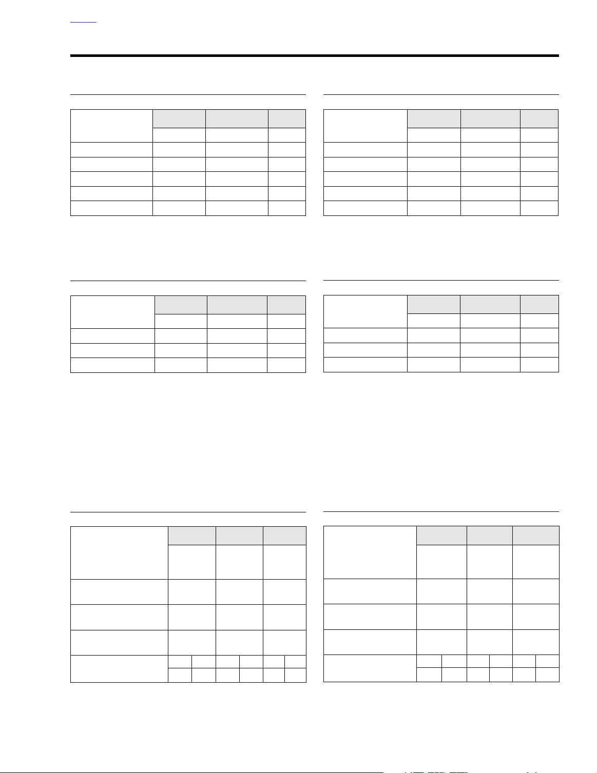
SPECIFICATIONS 2.1
DIMENSIONS (IN.)
FLHT/C/U
Wheel Base 63.5 63.5 63.5
Overall Length
Overall Width 39.0
Road Clearance 5.12
Overall Height 61.0
Saddle Height* 27.3
With 180 Lb. Rider
*
93.7/97.5/98.3
FLHR/C/S FLTR
93.7 93.7
34.45/34.45/39.40
5.12/5.12/4.70
55.06/55.06/46.40
27.3/26.9/26.1
35.75
WEIGHT (LBS.)
FLHT/C/U FLHR/C/S FLTR
DRY WEIGHT** 758/776/788 723/710/721 731
GVWR 1259 1259 1259
GAWR – Front 500 500 500
GAWR – Rear 827 827 827
As shipped from the factory
**
5.12
55.0
26.9
DIMENSIONS (MM)
FLHT/C/U
Wheel Base 1613 1613 1613
Overall Length
Overall Width 990
Road Clearance 130
Overall Height 1549
Saddle Height* 693
With 81.6 kg Rider
*
2380/2476/2497
FLHR/C/S FLTR
2380 2380
875/875/1001
130/130/119
1399/1399/1179
693/683/663
1397
WEIGHT (KG)
FLHT/C/U
DRY WEIGHT** 344/352/358 328/322/327 332
GVWR 571 571 571
GAWR – Front 227 227 227
GAWR – Rear 375 375 375
As shipped from the factory
**
FLHR/C/S FLTR
908
130
683
NOTE
Gross Vehicle Weight Rating (GVWR) (maximum allowable
loaded vehicle weight) and corresponding Gross Axle Weight
Ratings (GAWR) are given on a label located on the inside of
the right front frame downtube.
CAPACITIES (U.S.)
FLHT/C/U
Fuel Tank (gallons)
To tal***
Reserve
Oil Tank (quarts)
with filter 4 4 4
Tr ansmission
(Ounces, approximate) 20-24 20-24 20-24
Primary Chaincase
(Ounces, approximate) 32 32 32
Front Fork (Ounces)
***
Includes Reserve on Carbureted Models
0.9
Left Right Left Right Left Right
10.0 11.1 11.1 11.1 10.0 11.1
FLHR/C/S FLTR
5
5
0.9
5
0.9
CAPACITIES (METRIC)
FLHT/C/U
Fuel Tank (liters)
To tal***
Reserve
Oil Tank (liters)
with filter 3.78 3.78 3.78
Tr an smission
(Milliliters) 591-710 591-710 591-710
Primary Chaincase
(Milliliters) 946 946 946
Front Fork (Milliliters)
Includes Reserve on Carbureted Models
***
18.9
3.4
Left Right Left Right Left Right
295 328 328 328 295 328
FLHR/C/S FLTR
18.9
3.4
18.9
3.4
2004 Touring: Chassis 2-1
Page 2
HOME
TIRE DATA
11WARNING1WARNING
Tires, rims and air valves must be correctly matched to
wheel rims. See your Harley-Davidson dealer for service.
Mismatching tires, tubes, rims and air valves may result
in damage to the tire bead during mounting or may allow
the tire to slip on the rim, possibly causing tire failure,
which could result in death or serious injury.
11WARNING1WARNING
Using tires in ways other than those specified below may
adversely affect motorcycle stability. Instability may lead
to loss of vehicle control, which could result in death or
serious injury.
Use tubeless tires on all Harley-Davidson cast and
●
disc wheels.
●
Tubeless tires fitted with the correct size inner tubes
also may be used on all Harley-davidson laced
wheels, but protective rubber rim strips must be
installed to prevent damage to the inner tubes.
●
Do not use inner tubes in radial tires. Do not use
radial tires on laced wheels.
Always use the correct size tires and tubes. Tire
●
sizes are molded on the tire sidewall. Tube sizes are
printed on the tube.
11WARNING1WARNING
Maximum inflation pressure must not exceed specification on tire sidewall. Exceeding inflation specifications
can adversely affect handling or result in tire failure,
which could result in death or serious injury.
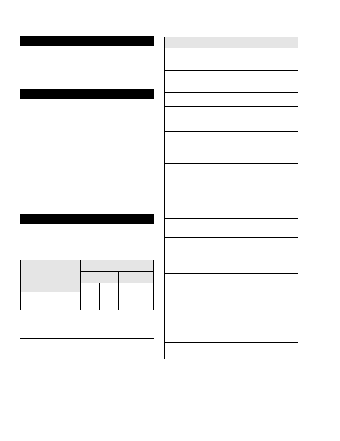
Tire Pressure (Cold)
Dunlop Tires
Only
Front Rear
PSI BARS PSI BARS
Solo Rider 36 2.5 36 2.5
Rider & One Passenger 36 2.5 40 2.8
REAR WHEEL SPROCKET
All Models 70 teeth
TORQUE VALUES
Item
Front brake disc TORX
screws
Front axle nut
Front axle holder nuts
Front brake caliper
mounting bolts
Rear brake disc TORX
screws
Rear wheel sprocket bolts 55-65 ft-lbs
Rear axle cone nut 95-105 ft-lbs 129-142 Nm
Wheel spokes
Front engine mount to
frame bolts
Front engine mounting
bracket to rubber mount
bolt
Voltage regulator locknuts
Handlebar clamp to
master cylinder housing
TORX screws
Brake caliper bleeder
valve
Rear brake pedal shaft
locknut
Brake pedal/master
cylinder assembly to
mounting bracket hex nut
Banjo bolt to master
cylinder
Banjo bolt to brake caliper
Fairing lower U-bolt
retainer locknuts
Fairing lower to engine
guard clamp TORX screw
Fairing lower cap screws
Front brake master
cylinder reservoir cover
screws
Rear brake master
cylinder reservoir cover
screws
Brake caliper pad pins
Brake caliper bridge bolts
ft/in-lbs Nm
16-24 ft-lbs 22-33 Nm
50-55 ft-lbs
132-180
in-lbs
28-38 ft-lbs
30-45 ft-lbs
40-50
in-lbs
15-20 ft-lbs 20-27 Nm
15-20 ft-lbs 20-27 Nm
70-100
in-lbs
60-80
in-lbs
80-100
in-lbs
15-20 ft-lbs
30-40 ft-lbs 41-54 Nm
17-22 ft-lbs 23-30 Nm
17-22 ft-lbs 23-30 Nm
35-40
in-lbs
90-100
in-lbs
10-15
in-lbs
6-8
in-lbs
6-8
in-lbs
180-200
in-lbs
28-38 ft-lbs 38-52 Nm
68-75 Nm
14.9-20.3 Nm
37.9-51.5 Nm
41-61 Nm
75-88 Nm
4.5-5.6 Nm
7.9-11.3 Nm
6.8-9.0 Nm
9.0-11.3 Nm
20-27 Nm
4.0-4.5 Nm
10.2-11.3 Nm
1.1-1.7 Nm
0.7-0.9 Nm
0.7-0.9 Nm
20-23 Nm
Continued ...
2-2 2004 Touring: Chassis
Page 3
HOME
TORQUE VALUES (CONT.’D)
Item
Fork oil drain plugs
Fork pinch bolts
Fork stem nut
Fork tube plug
Fork cap bolt
Damper rod/cartridge
6mm screw
Damper rod locknut
(cartridge type fork)
Shock bottom mounting
bolt
Shock top mounting bolt
Rear swingarm bracket
bolts
Rear swingarm pivot shaft
locknut
Handlebar switch
housing TORX screws
Handlebar clamp to clutch
lever bracket screws
Clutch release cover
socket head screws
Clutch cable fitting 36-60
Tr ansmission lubricant
drain plug
Tr ansmission filler plug/
dipstick
Battery cable bolt
Tour-Pak mounting bolts
Inner fairing screws
Outer fairing screws
(below windshield)
Fairing cap TORX screws
Speedometer/tachometer
bracket socket screws
2 inch diameter gauge
nuts
Passing lamp bracket fork
bracket TORX bolts
Windshield wellnut
screws (FLTR)
Front turn signal lamp
bracket stud acorn nuts
(FLTR)
ft/in-lbs Nm
72-96
30-35 ft-lbs
60-80 ft-lbs
22-58 ft-lbs
50-60 ft-lbs
132-216
13-20 ft-lbs
35-40 ft-lbs
33-35 ft-lbs
34-42 ft-lbs
40-45 ft-lbs
35-45
60-80
120-144
14-21 ft-lbs
25-75
60-96
96-120
20-30
25-30
25-30
10-20
10-20
15-20 ft-lbs 20-27 Nm
6-13
40-50
in-lbs
in-lbs
in-lbs
in-lbs
in-lbs
in-lbs
in-lbs
in-lbs
in-lbs
in-lbs
in-lbs
in-lbs
in-lbs
in-lbs
in-lbs
in-lbs
8-11 Nm
41-48 Nm
81-109 Nm
30-79 Nm
68-81 Nm
14.9-24.4 Nm
18-27 Nm
47-54 Nm
45-48 Nm
46-57 Nm
54-61 Nm
4-5 Nm
6.8-9.0 Nm
13.6-16.3 Nm
4-7 Nm
19-28 Nm
2.8-8.5 Nm
6.8-10.9 Nm
10.8-13.5 Nm
2.3-3.4 Nm
2.8-3.4 Nm
2.8-3.4 Nm
1.1-2.3 Nm
1.1-2.3 Nm
0.7-1.5 Nm
4.5-5.7 Nm
Continued ...
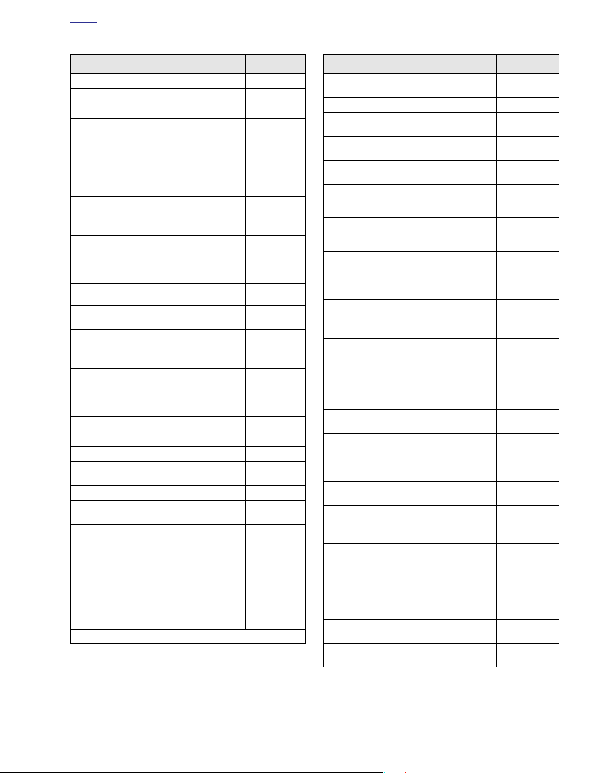
Item
Short fairing screws
(FLTR)
Long fairing screws (FLTR)
Instrument bezel TORX
screws (FLTR)
Instrument nacelle to fork
bracket TORX bolts (FLTR)
Fairing bracket/steering
head thru bolt (FLTR)
Radio bracket/inner fairing
to fairing bracket stud locknuts (FLTR)
Headlamp nacelle handlebar clamp shroud Phillips
screw
Headlamp nacelle trim
strip flange nut
Passing lamp bracket fork
bracket stud acorn nuts
Front fender mounting
bolts
Rear fender TORX bolts
Jiffy stand leg stop flange
nut
Intake flange adapter
screws
Exhaust flange adapter
nuts
Exhaust pipe TORCA
clamps
Heat shield worm drive
clamps
Tr ansmission exhaust
bracket clamp bolt
Passenger footboard/
footrest socket screws
Rider footboard
pivot bolt nut
Air valve mount hex nut 40-50
Handlebar upper clamp
screws
Handlebar lower clamp
bolts (risers)
Ignition switch
nut
Speaker box to
Tour-Pak bolts
Throttle cable J-clamp
screw to wellnut (FLHR/C)
DOM 50-70
HDI 125-150
ft/in-lbs Nm
6-12
10-15
25-35
15-20 ft-lbs 20-27 Nm
20-30 ft-lbs 27.1-40.7 Nm
96-144
10-20
15-20
72-108
16-20 ft-lbs 22-27 Nm
15-20 ft-lbs 20-27 Nm
43-53 ft-lbs 58-72 Nm
96-144
100-120
45-60 ft-lbs 61-81 Nm
20-40
60-96
15-18 ft-lbs 20-24 Nm
84-108
12-16 ft-lbs 16.3-21.7 Nm
30-40 ft-lbs 40.7-54.2 Nm
25-35
9-18
in-lbs
in-lbs
in-lbs
in-lbs
in-lbs
in-lbs
in-lbs
in-lbs
in-lbs
in-lbs
in-lbs
in-lbs
in-lbs
in-lbs
in-lbs
in-lbs
in-lbs
0.7-1.4 Nm
1.1-1.7 Nm
2.8-4.0 Nm
10.9-16.3 Nm
1.1-2.3 Nm
1.7-2.3 Nm
8.1-12.2 Nm
10.9-16.3 Nm
11.3-13.6 Nm
2.3-4.5 Nm
6.8-10.8 Nm
9.5-12.2 Nm
4.5-5.6 Nm
5.7-7.9 Nm
14.1-16.9 Nm
2.8-4.0 Nm
1.0-2.0 Nm
2004 Touring: Chassis 2-3
Page 4

HOME
NOTES
2-4 2004 Touring: Chassis
Page 5
HOME
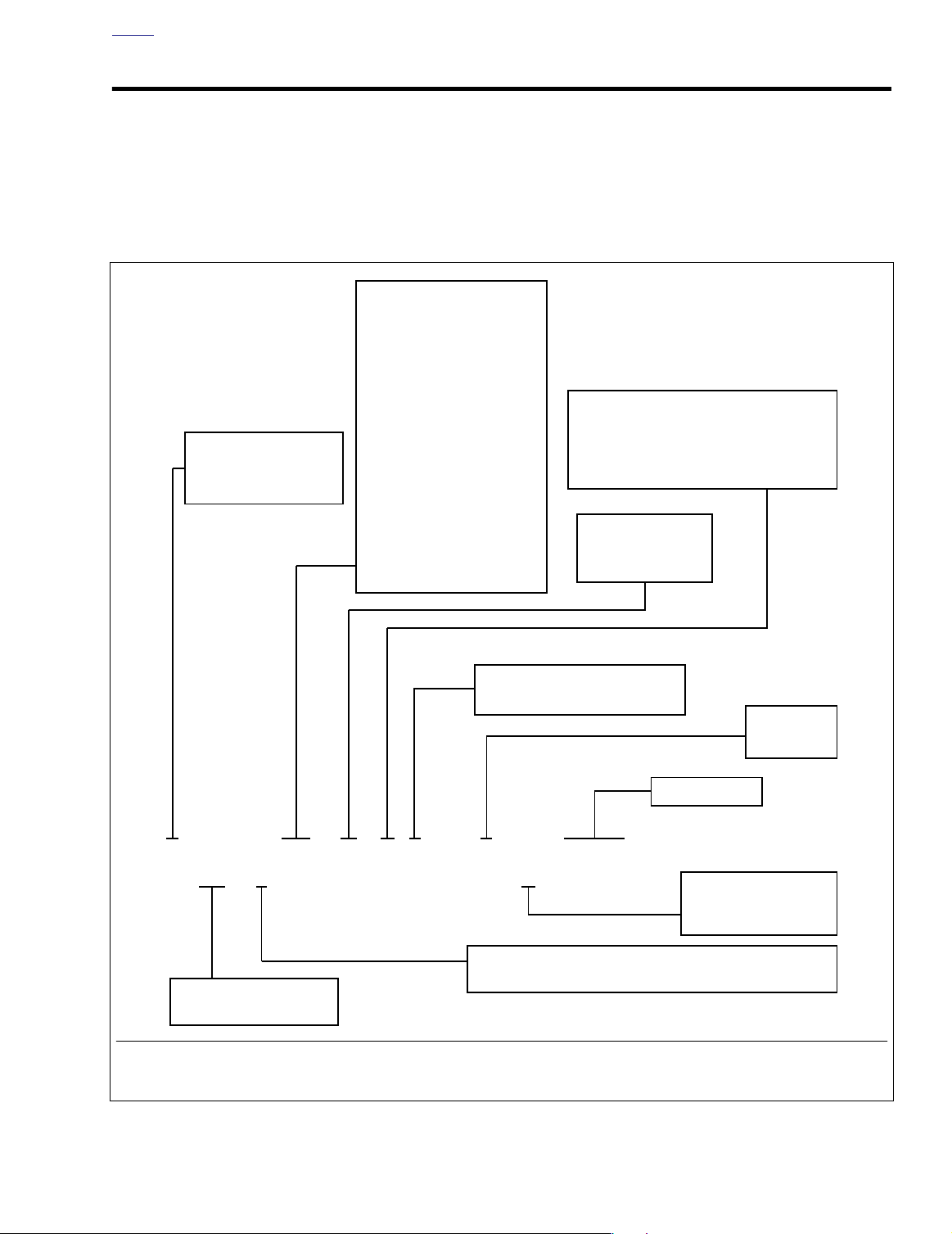
VEHICLE IDENTIFICATION NUMBER (VIN) 2.2
A 17-digit serial number, or Vehicle Identification Number
(VIN), is stamped on the right side of the frame backbone at
the rear of the steering head (and under the main harness
conduit). A label bearing the VIN code is also affixed to the
left side of the steering head. An abbreviated VIN is stamped
between the front and rear cylinders on the left side of the
crankcase.
Model Designation
DD – FLHT
DJ – FLHTC
FB – FLHRI
FC – FLHTCUI
FD – FLHR
FF – FLHTCI
FG – FLHTCUI W/SC
FH – FLHPI
Market Designation
1 = Domestic
5 = International (HDI)
FK – FLHTCI Shrine
FL – FLHTCUI Shrine
FM – FLHTPI
FR – FLHRCI
FS – FLTRI
FT – FLHPEI
FV – FLHTI
FW – FLHRI Shrine
FX – FLHRS
FY – FLHRSI
NOTE
Always give the complete VIN when ordering parts or making
an inquiry about your motorcycle.
Introduction Date and Special Models
1 = Regular introduction date
2 = Mid-year introduction date
3 = California model
4 = Anniversary model
Engine Type
V = Carbureted
W = Fuel Injected
VIN Check Digit
Var ies; can be 0 through 9, or X.
1HD 1DJ V 13 4 Y 500001
Motorcycle Type
1 = Heavyweight (901 cc and larger engine displacement)
Manufacturer and Make
Harley-Davidson
Sample VIN as it appears on the steering head –1HD1DJV134Y500001
Sample abbreviated VIN as it appears on the engine crankcase– DJV4500001
Figure 2-1. Vehicle Identification Number (VIN)
Model Year
4 = 2004
Serial Number
Assembly Plant
Y = York, PA
K = Kansas City, MO
2004 Touring: Chassis 2-5
Page 6
HOME
FRONT WHEEL 2.3
GENERAL
Maximum tire mileage and good handling qualities are
directly related to care given wheels and tires. Wheels and
tires should be regularly inspected for wear. If handling problems occur, see Section 1.1 TROUBLESHOOTING, HAN-
DLING, for possible causes.
Always keep tires inflated to the recommended pressure and
balance the wheel whenever a tire or tube is replaced.
PRELIMINARY INSPECTION
1. Measure brake disc thickness for excessive wear. Minimum acceptable thickness is stamped on side of disc.
Also replace discs if warped or badly scored. Obtain
new
T40 TORX screws if brake discs were removed.
2. Whenever the wheel is removed for tire replacement or
any other purpose, inspect the wheel bearings as follows:
a. Insert finger into wheel bearing and rotate the inner
race in both directions. Repeat step on opposite
side of wheel.
b. Replace the wheel bearings if there is rough rota-
tion, abnormal noise or anything unusual. Always
replace wheel bearings as a set. Never replace just
one wheel bearing.
2. Remove both the upper and lower mounting bolts from
lugs of front fork leg to release brake caliper assembly.
3. Lift caliper upward to remove from brake disc. Allow the
caliper to hang loose.
4. Repeat steps 1 thru 3 to release caliper on opposite side
of wheel.
NOTE
Do not operate the front brake hand lever with the front wheel
removed or the caliper pistons may be forced out. Reseating
pistons requires disassembly of the caliper.
5. Insert screwdriver or steel rod through hole in axle on
right side of vehicle. While holding axle stationary,
remove the axle nut, lockwasher and flat washer on the
left side.
6. Loosen the two axle holder nuts at bottom of right side
fork leg.
7. With soft mallet, tap axle toward right side of vehicle until
loose. Catching external spacers on left and right side,
pull axle from hub while supporting wheel.
8. Move wheel to bench area and inspect bearings. See
PRELIMINARY INSPECTION on this page.
REMOVAL
1. Use shop rag or tape to protect fender area adjacent to
caliper, as incidental contact can occur during caliper
removal.
9428
Figure 2-2. Inspect Wheel Bearings
DISASSEMBLY
1. If wheel bearing replacement is necessary, proceed as
follows:
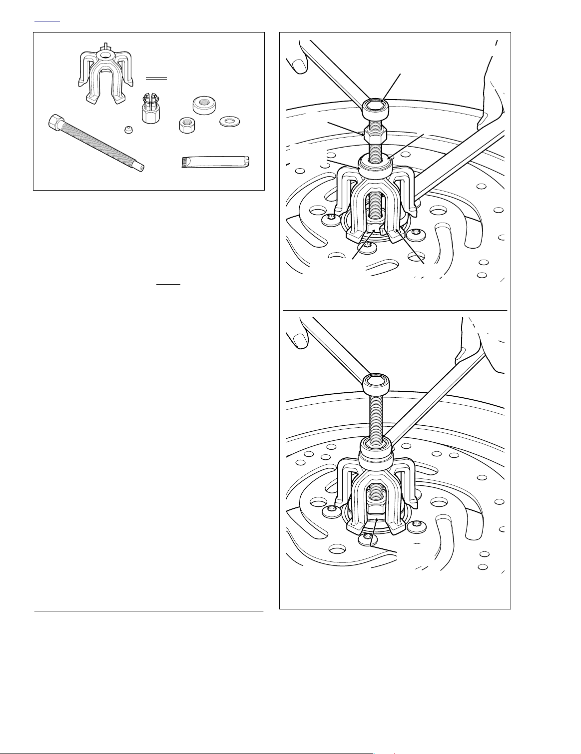
a. Obtain the WHEEL BEARING REMOVER/IN-
STALLER (HD-44060). Pick out the wheel bearing
remover tools for the front wheel. See Figure 2-3.
b. To prolong service life and ensure smooth opera-
tion, sparingly apply graphite lubricant to threads of
forcing screw.
c. Install hex nut, flat washer and Nice bearing on forc-
ing screw. Insert end of forcing screw through hole
in bridge.
d. Install steel ball inside
end of forcing screw.
e. Insert collet into bearing ID. Feel for inside edge of
bearing using lip at end of collet and then back off
slightly.
f. Holding forcing screw to prevent rotation, turn hex
on collet until lip makes firm contact with inside
edge of bearing. See upper frame of Figure 2-4.
lar
collet. Install collet at
ger
2-6 2004 Touring: Chassis
Page 7
HOME
f1775x2x
Wheel
Bearing
f1774x2x
Nice
Bearing
Hex
Nut
Forcing
Screw
Flat
Washer
Bridge
Collet Hex
with Ball Bearing
Hold Forcing Screw and Turn Hex on Collet to Expand.
Hold Forcing Screw and Turn Hex Nut to Pull Out Bearing.
Bridge
ger Collet
Lar
1 Inch
Steel Ball
Forcing Screw
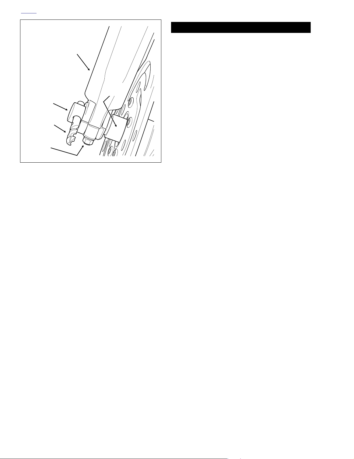
Figure 2-3. Front Wheel Bearing Remover Tools
(Part No. HD-44060)
g. Holding forcing screw, turn hex nut until bearing is
free. See lower frame of Figure 2-4.
h. Remove spacer sleeve from wheel hub.
i. Repeat procedure to remove bearing on opposite
side of wheel. Discard bearings.
2. If brake disc replacement is necessary, use a T40 TORX
drive head and remove five screws securing brake disc
to hub. Discard TORX screws. Repeat procedure to
remove disc on opposite side of wheel. If the wheel is to
be assembled with the same discs, mark both the wheel
and discs, so that they can be installed in their original
positions.
3. If tire replacement is necessary, see Section 2.8 TIRES
AND TUBES.
4. If the wheel is laced, and hub, spoke or rim replacement
is necessary, loosen all spoke nipples and disassemble
hub from rim.
Nice Bearing
Hex Nut
Graphite Lubricant
f1769x2x
Flat Washer
CLEANING AND INSPECTION
1. Thoroughly clean all parts in solvent.
2. Inspect all parts for damage or excessive wear.
3. Always replace bearing assemblies as a complete set.
4. Inspect brake discs. Replace discs if warped or badly
scored. Measure disc thickness for excessive wear. Minimum acceptable thickness is stamped on side of disc.
ASSEMBLY
1. On laced wheels, if the hub and rim were disassembled,
assemble the hub, spokes and rim. See Section 2.6
WHEEL LACING - 16 INCH RIM.
Figure 2-4. Remove Sealed Wheel Bearings
2004 Touring: Chassis 2-7
Page 8
HOME
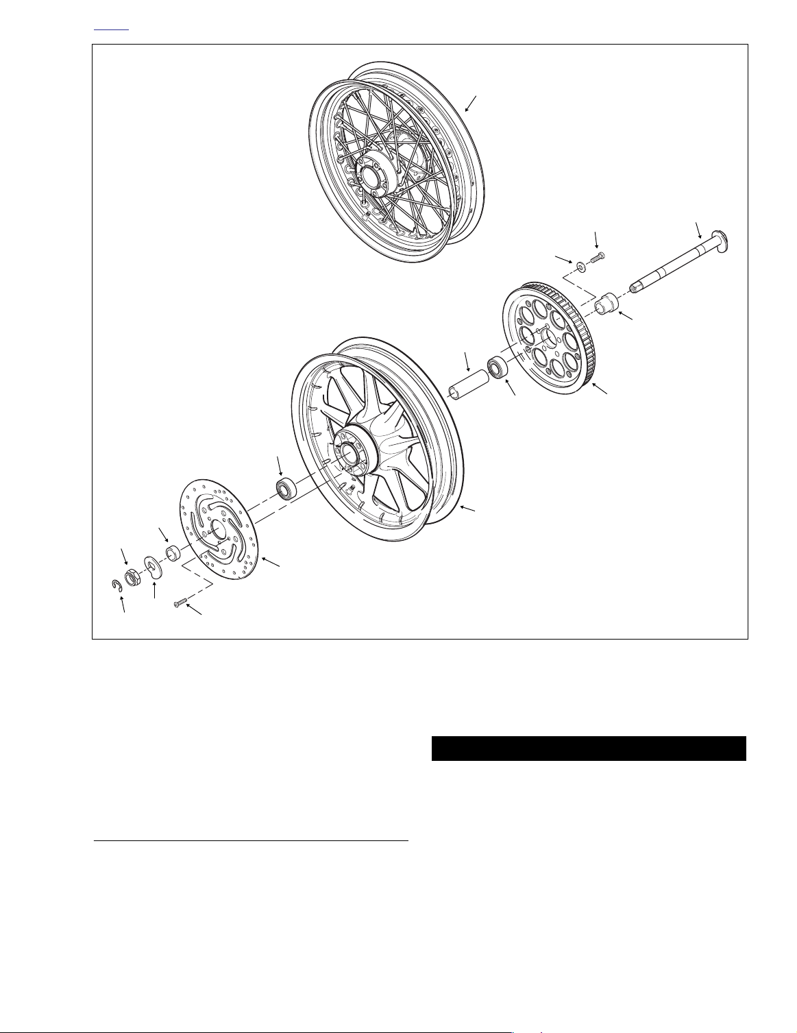
1. Axle Nut
2. Lockwasher
3. Flat Washer
4. T40 Torx Screw (10)
5. Brake Disc (Left Side)
6. External Spacer (Long)
7. Sealed Bearing (2)
8. Cast Wheel
9. Spacer Sleeve
10. Brake Disc (Right Side)
11. External Spacer (Short)
12. Axle
13. Laced Wheel
13
Left Side
4
1
2
3
Right Side
4
9
7
12
11
10
Figure 2-5. Front Wheel (Exploded View)
11WARNING1WARNING
Do not allow brake fluid or other lubricants to contact
the brake disc. Such contact can adversely affect braking ability, which could result in death or serious injury.
2. Using a T40 TORX drive head, install brake discs on hub
using
new
screws. Be sure to install discs in their original positions. Alternately tighten screws to 16-24 ft-lbs
(22-33 Nm).
3. Install
Always install first of two bearings on the left side (opposite
the valve stem side of the wheel).
new
wheel bearings as follows:
NOTE
6
5
7
8
f2042x2x
a. Obtain the WHEEL BEARING REMOVER/IN-
STALLER (HD-44060). Pick out the wheel bearing
installer tools for the front wheel. See Figure 2-6.
b. To prolong service life and ensure smooth opera-
tion, sparingly apply graphite lubricant to threads of
threaded rod.
c. Slide support plate onto threaded rod. Slide rod
through hub on the valve stem side of the wheel.
See upper frame of Figure 2-7.
d. On opposite side of wheel, slide bearing onto
threaded rod with lettered side facing outboard.
e. Install
lar
pilot, Nice bearing, flat washer and
ger
hex nut onto rod.
2-8 2004 Touring: Chassis
Page 9
HOME
f1777x2x
Support
Plate
Threaded
Rod
f1773x2x
Nice
Bearing
Hex
Nut
Threaded
Rod
Flat
Washer
Wheel
Bearing
Pilot
Slide Threaded Rod (with Support Plate) Through Hub.
Hold Threaded Rod and Turn Hex Nut to Push In Bearing.
Nice Bearing
Larger Pilot
1 Inch
Support Plate
Hex Nut
Graphite Lubricant
Flat Washer
Threaded Rod
f1771x2x
Figure 2-6. Front Wheel Bearing Installer Tools
(Part No. HD-44060)
f. Holding threaded rod on opposite side of wheel to
prevent rotation, turn hex nut to install bearing. See
lower frame of Figure 2-7. Bearing is fully seated
when it makes firm contact with the counterbore.
g. Disassemble and remove tool, but leave support
plate on threaded rod.
h. Slide threaded rod through installed wheel bearing
and hub of wheel.
i. On the valve stem side of the wheel, slide spacer
sleeve down threaded rod until it contacts installed
wheel bearing.
j. Repeat steps 3(d) through 3(g) to complete installa-
tion of second wheel bearing. Bearing is fully seated
when hex nut can no longer be turned.
4. Verify that wheel is true. See CHECKING CAST RIM
RUNOUT or TRUING LACED WHEEL, whichever
applies.
5. Install rim strip on wheel rim, if applicable. Install tube
and tire, if applicable. Verify that wheel is balanced.
INSTALLATION
1. Place wheel into position between forks with the valve
stem on the right side of the vehicle.
2. Coat the axle with ANTI-SIEZE LUBRICANT.
right fork leg. Push axle through fork,
spacer and wheel hub until it begins to emerge from left
side.
3. Supporting wheel, insert threaded end of axle through
4. With the three notches on the bearing side, push axle
through
long
external spacer and left fork leg until axle
shoulder contacts external spacer on right fork side.
shor
t
external
Figure 2-7. Install Sealed Wheel Bearings
5. Install flat washer, lockwasher and axle nut.
6. Insert screwdriver or steel rod through hole in axle on
right side of vehicle. While holding axle stationary,
tighten axle nut to 50-55 ft-lbs (68-75 Nm).
7. Insert 7/16 inch drill bit into hole in axle. See Figure 2-8.
8. Pull fork leg so that it just contacts drill bit, and then
tighten axle holder nuts to 132-180
in-lbs
(14.9-20.3
Nm).
2004 Touring: Chassis 2-9
Page 10
HOME
f1783x2x
Fork Leg
Right Side
Axle
Drill Bit
Axle Holder
Nuts
Figure 2-8. Align Front Wheel
9. Remove drill bit from axle hole.
10. Install brake caliper as follows:
Short
Spacer
11WARNING1WARNING
After installation of calipers and BEFORE moving motorcycle, pump front brake hand lever until pistons push
pads against the brake discs. If fluid pressure is not
pumped up, the brake will not be available the first time it
is used, a situation that could result in death or serious
injury.
11. Depress front brake hand lever several times to set
brake pads to proper operating position within caliper.
a. Use shop rag or tape to protect fender area adja-
cent to caliper, as incidental contact can occur during caliper installation.
b. With the bleeder valve topside, position caliper so
that brake disc is situated between friction pads. Pry
inner and outer brake pads back for additional clearance, if necessary.
c. Align upper mounting hole in caliper with upper
mounting lug on fork leg. Loosely install long caliper
mounting bolt into upper lug of fork leg.
d. Install short caliper mounting bolt into lower lug of
fork leg. Tighten lower mounting bolt to 28-38 ft-lbs
(37.9-51.5 Nm).
e. Tighten upper caliper mounting bolt to 28-38 ft-lbs
(37.9-51.5 Nm).
f. Repeat step 10 to install caliper on opposite side of
wheel.
2-10 2004 Touring: Chassis
Page 11

HOME
REAR WHEEL 2.4
GENERAL
Maximum tire mileage and good handling qualities are
directly related to care given wheels and tires. Wheels and
tires should be regularly inspected for wear. If handling problems occur, see Section 1.1 TROUBLESHOOTING, HAN-
DLING, for possible causes.
Always keep tires inflated to the recommended pressure and
balance the wheel whenever a tire or tube is replaced.
PRELIMINARY INSPECTION
1. Measure brake disc thickness for excessive wear. Minimum acceptable thickness is stamped on side of disc.
Also replace disc if warped or badly scored.
2. Whenever the wheel is removed for tire replacement or
any other purpose, inspect the wheel bearings as follows:
a. Insert finger into wheel bearing and rotate the inner
race. Repeat step on opposite side of wheel.
b. Replace the wheel bearings if there is rough rota-
tion, abnormal noise or anything unusual. Always
replace wheel bearings as a set. Never replace just
one wheel bearing.
c. Loosen TORCA clamp between rear header pipe
and muffer.
d. Remove two bolts (with lockwashers) to detach muf-
fler from the lower saddlebag support rail.
e. Remove bungee cord to release muffler from lower
saddlebag support rail.
3. Standing on right side of vehicle, remove E-clip from
groove at end of axle.
4. Remove cone nut and adjuster cam from axle.
5. Using a soft mallet, gently tap end of axle towards left
side to loosen. Catching external spacers on right and
left side of hub, pull axle free of wheel and rear
swingarm.
6. Pull wheel to release brake disc from caliper. Pry inner
and outer brake pads back for additional clearance, if
necessary. Use a putty knife with a wide thin blade to
avoid scoring or scratching the brake disc.
7. Remove caliper from anchor weldment on rear swingarm, and carefully hang over lower saddlebag support
rail.
8. Move wheel forward and slip belt off sprocket.
9. Move wheel to bench area and inspect bearings. See
PRELIMINARY INSPECTION on this page.
REMOVAL
1. Remove saddlebags. See Section 2.25 SADDLEBAG,
REMOVAL.
2. Remove both mufflers as follows:
Left Side
a. Open worm drive clamps to remove heat shield
from crossover pipe.
b. Using a bungee cord, tie the muffler to the lower
saddlebag support rail.
c. Loosen TORCA clamp between crossover pipe and
muffer.
d. Remove two bolts (with lockwashers) to detach muf-
fler from the lower saddlebag support rail.
e. Remove bungee cord to release muffler from lower
saddlebag support rail.
Right Side
a. Open worm drive clamps to remove heat shield
from rear header pipe.
b. Using a bungee cord, tie the muffler to the lower
saddlebag support rail.
NOTE
Do not operate the rear brake pedal with the rear wheel
removed or the caliper pistons may be forced out. Reseating
pistons requires disassembly of the caliper.
DISASSEMBLY
1. If wheel bearing replacement is necessary, proceed as
follows:
a. Remove five bolts (with flat washers) securing belt
sprocket to hub.
b. Obtain the WHEEL BEARING REMOVER/IN-
STALLER (HD-44060). Pick out the wheel bearing
remover tools for the rear wheel. See Figure 2-9.
NOTE
The smaller 3/4 inch collet (and pilot) is only used to replace
the rear
wheel bearings on 2000-01 Touring models.
c. To prolong service life and ensure smooth opera-
tion, sparingly apply graphite lubricant to threads of
forcing screw.
2004 Touring: Chassis 2-11
Page 12
HOME
Bridge
Forcing Screw
Steel Ball
ger Collet
Lar
1 Inch
Hex Nut
Graphite Lubricant
f1769x2x
Nice Bearing
Flat Washer
Figure 2-9. Rear Wheel Bearing Remover Tools
(Part No. HD-44060)
d. Install nut, flat washer and Nice bearing on forcing
screw. Insert end of forcing screw through hole in
bridge.
e. Install steel ball inside
lar
collet. Install collet at
ger
end of forcing screw.
f. Insert collet into bearing ID. Feel for inside edge of
bearing using lip at end of collet and then back off
slightly.
Forcing
Screw
Hex
Nut
Flat
Washer
Nice
Bearing
Collet Hex
with Ball Bearing
Hold Forcing Screw and Turn Hex on Collet to Expand.
Bridge
f1774x2x
f1775x2x
g. Holding forcing screw to prevent rotation, turn hex
on collet until lip makes firm contact with inside
edge of bearing. See upper frame of Figure 2-10.
h. Holding forcing screw, turn hex nut until bearing is
free. See lower frame of Figure 2-10.
i. Remove spacer sleeve from wheel hub.
j. Repeat procedure to remove bearing on opposite
side of wheel. Discard bearings.
2. If brake disc replacement is necessary, use a T45 TORX
drive head and remove five screws securing brake disc
to hub. If the wheel is to be assembled with the same
disc, mark both the wheel and disc, so that it can be
installed in its original position.
3. Remove tire, if necessary. Remove tube from the rim, if
applicable. See Section 2.8 TIRES AND TUBES.
4. If it is necessary to remove the hub from a laced wheel,
loosen all spoke nipples and remove the rim and spokes.
CLEANING AND INSPECTION
1. Thoroughly clean all parts in solvent.
Wheel
Bearing
Hold Forcing Screw and Turn Hex Nut to Pull Out Bearing.
Figure 2-10. Remove Sealed Wheel Bearings
2. Inspect all parts for damage or excessive wear.
2-12 2004 Touring: Chassis
3. Always replace bearings as a complete set.
Page 13
HOME
11WARNING1WARNING
1. Axle
2. External Spacer (Large)
3. Bolt (5)
4. Flat Washer (5)
5. Belt Sprocket
6. Sealed Bearing (2)
7. Spacer Sleeve
8. Cast Wheel
9. Brake Disc
10. T45 TORX Screw (5)
11. External Spacer (Small)
12. Adjuster Cam
13. Cone Nut
14. E-Clip
15. Laced Wheel
Right Side
15
Left Side
3
1
4
2
7
6
11
13
9
12
14
4. Inspect brake disc. Replace disc if warped or badly
scored. Measure disc thickness for excessive wear. Minimum acceptable thickness is stamped on side of disc.
5. Check the belt sprocket for wear, tooth damage, cracks
or pitting. Replace if necessary.
6. On laced wheels, replace spokes, rim or hub if damaged.
10
Figure 2-11. Rear Wheel (Exploded View)
ASSEMBLY
1. On laced wheels, if the hub and rim were disassembled,
assemble the hub, spokes and rim. See Section 2.6
WHEEL LACING - 16 INCH RIM.
6
5
8
f2044x2x
2. Verify that wheel is true. See Section 2.5 CHECKING
RIM RUNOUT or Section 2.7 TRUING LACED WHEEL,
whichever applies.
Do not allow brake fluid or other lubricants to contact
the brake disc. Such contact can adversely affect braking ability, which could result in death or serious injury.
3. Using a T45 TORX drive head, install five screws (and
locknuts on laced wheels) to secure brake disc to hub.
Always install brake disc in its original position. Use
screws after three use cycles. Alternately tighten screws
to 30-45 ft-lbs (41-61 Nm).
new
2004 Touring: Chassis 2-13
Page 14

HOME
Nice Bearing
Larger Pilot
1 Inch
Support Plate
Support
Plate
Hex Nut
Graphite Lubricant
Flat Washer
Threaded Rod
f1771x2x
Figure 2-12. Rear Wheel Bearing Installer Tools
(Part No. HD-44060)
4. Install
new
wheel bearings as follows:
NOTE
Always install first of two bearings on the right side (the valve
stem side of the wheel).
a. Obtain the WHEEL BEARING REMOVER/IN-
STALLER (HD-44060). Pick out the wheel bearing
installer tools for the rear wheel. See Figure 2-12.
b. To prolong service life and ensure smooth opera-
tion, sparingly apply graphite lubricant to threads of
threaded rod.
c. Slide support plate onto threaded rod. Slide rod
through hub on the sprocket side of the wheel. See
upper frame of Figure 2-13.
d. On the valve stem side of the wheel, slide bearing
onto threaded rod with lettered side facing outboard.
e. Install
lar
pilot, Nice bearing, flat washer and
ger
hex nut onto rod.
f. Holding threaded rod on opposite side of wheel to
prevent rotation, turn hex nut to install bearing. See
lower frame of Figure 2-13. Bearing is fully seated
when it makes firm contact with the counterbore.
g. Disassemble and remove tool, but leave support
plate on threaded rod.
h. Slide threaded rod through installed wheel bearing
and hub of wheel.
i. On the other side of the wheel, slide spacer sleeve
down threaded rod until it contacts installed wheel
bearing.
j. Repeat steps 4(d) through 4(g) to complete installa-
tion of second wheel bearing. Bearing is fully seated
when hex nut can no longer be turned.
5. Install rim strip on wheel rim, if applicable. Install tube
and tire, if applicable. Verify that wheel is balanced.
Threaded
Rod
f1777x2x
Slide Threaded Rod (with Support Plate) Through Hub.
Wheel
Bearing
Nice
Bearing
Pilot
Threaded
Rod
f1773x2x
Hold Threaded Rod and Turn Hex Nut to Push In Bearing.
Hex
Nut
Flat
Washer
Figure 2-13. Install Sealed Wheel Bearings
6. Apply two drops of Loctite High Strength Threadlocker
271 (red) to threads of five belt sprocket bolts. Always
use
new
bolts after three use cycles. Install bolts with
flat washers to secure sprocket to hub. Alternately
tighten bolts to 55-65 ft-lbs (75-88 Nm).
INSTALLATION
1. Place wheel in rear swingarm. Slide wheel far enough
forward to slip belt over sprocket and then slide the
wheel back.
2-14 2004 Touring: Chassis
Page 15
HOME
CAUTION
lbs. (4.5 kg) of force at the midpoint of the bottom belt
strand. Belt deflection should be as follows:
Do not bend or fold belt backward or into loops smaller
than 5 inches (127 mm) in diameter. Sharp bending can
weaken the belt and cause premature failure.
2. Seat caliper on anchor weldment of rear swingarm. Position wheel in swingarm, so that brake disc is centered
between brake pads.
3. Coat the axle with ANTI-SIEZE LUBRICANT.
4. With the larger OD on the outboard side, hold external
spacer between rear swingarm and belt sprocket. Slide
axle through left side of rear swingarm, external spacer,
and belt sprocket into wheel hub.
5. When axle emerges from hub on brake disc side of
wheel, push axle through
shor
external spacer, caliper
t
bracket and right side of rear swingarm.
6. Rotate axle so that the flat on the threaded end is topside. With the thumb down and the cam forward, install
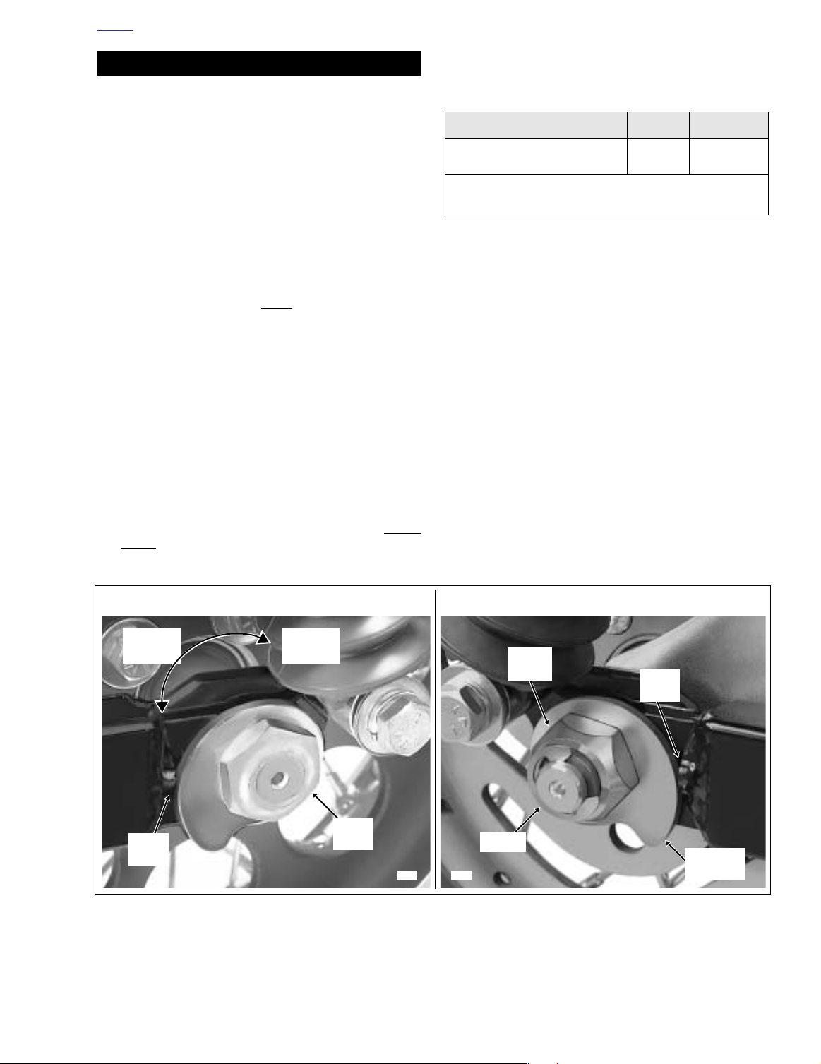
adjuster cam on end of axle.
7. Apply a thin film of ANTI-SIEZE LUBRICANT to the
inboard side of the cone nut avoiding contact with
threads. Install cone nut on axle, but finger tighten only.
8. Verify that adjuster cam just contacts weld nub on both
sides of rear swingarm. If necessary, push wheel forward slightly to achieve the desired result. Snug the
cone nut to 15-20 ft-lbs (20-27 Nm). See Figure 2-14.
9. Check deflection at the loosest spot in the belt. Use
BELT TENSION GAUGE (HD-35381A), or install narro
saddle (HD-35381-3) on existing gauge, and apply 10
Table 2-1. Belt Deflection in the Air
Orientation
Motorcycle Upright
With Rear Wheel in the Air
See Section 6.4 SECONDARY DRIVE BELT AND SPROCKETS
for belt deflection specification with motorcycle on jiffy stand.
NOTE
10. If belt is too tight, move to step 11 to increase belt
deflection. If belt is too loose, reduce belt deflection as
described below:
a. Rotate weld nut on left side of axle in a clockwise
direction.
b. Check belt deflection. Apply 10 lbs. (4.5 kg) of force
at the midpoint of the bottom belt strand. Belt
deflection should be within the range specified in
Ta bl e 2-1.
c. If belt is still too loose, repeat steps 10(a) through
10(b). If belt is now too tight, move to step 11.
11. If belt is too tight, increase belt deflection as follows:
a. Rotate weld nut on left side of axle in a counter-
clockwise direction.
b. Push wheel forward slightly so that adjuster cam
w
just contacts weld nub on both sides of rear swingarm. See Figure 2-14.
Inches Millimeters
3/16 - 1/4 4.8 - 6.4
Increase
Belt
Deflection
Weld
Nub
Reduce
Belt
Deflection
Cone
Nut
Weld
Nub
Weld
Nut
8398
E-Clip
8407
Figure 2-14. Move Rear Wheel Forward Until Adjuster Cams Just Contact Weld Nubs
RIGHT SIDELEFT SIDE
Adjuster
Cam
2004 Touring: Chassis 2-15
Page 16

HOME
c. Check belt deflection. Apply 10 lbs. (4.5 kg) of force
at the midpoint of the bottom belt strand. Belt
deflection should be within the range specified in
Ta bl e 2-1.
d. If belt is still too tight, repeat steps 11(a) through
11(c). If belt is now too loose, move to step 10.
12.
Holding
right side to 95-105 ft-lbs (128.8-142.4 Nm).
If the axle moves during tightening of the cone nut, then the
the belt deflection procedure must be restarted.
13. Recheck belt deflection to verify that it is still within specification.
If the belt deflection is not within specification, loosen
cone nut and then snug to 15-20 ft-lbs (20-27 Nm)
before returning to step 10.
14. With the flat side out, install
side of axle.
15. Install both mufflers as follows:
TORCA muffler clamps have eliminated the need for silicone
or graphite tape during assembly. To ensure sealing integrity
of muffler clamps and prevent the possibility of leakage, Harley-Davidson recommends that TORCA clamp assemblies be
discarded and replaced each time they are removed.
weld nut on left side of axle, tighten cone nut on
NOTE
new
E-clip in groove on right
NOTE
Left Side
a. Slide
b. Using a bungee cord, tie muffler to lower saddlebag
c. Tighten the two bolts (with lockwashers) to fasten
new
TORCA clamp onto free end of crossover
pipe.
support rail. Install muffler on crossover pipe. Place
TORCA clamp into position between crossover and
muffler.
the muffler to the lower saddlebag support rail.
CAUTION
CAUTION
Verify that the heat shields do not contact the vehicle
frame or any mounted components. Contact will cancel
the effect of the rubber isolation mounts and transmit
vibration to the rider via the vehicle frame.
g. Remove bungee cord from muffler.
Right Side
a. Slide
b. Using a bungee cord, tie muffler to lower saddlebag
c. Tighten the two bolts (with lockwashers) to fasten
Verify that the exhaust pipes do not contact the vehicle
frame or any mounted components. Contact will cancel
the effect of the rubber isolation mounts and transmit
vibration to the rider via the vehicle frame.
d. Verify that exhaust pipes are in alignment and do
e. Tighten the TORCA clamp to 45-60 ft-lbs (61-81
f. Open worm drive clamps and install heat shield on
Verify that the heat shields do not contact the vehicle
frame or any mounted components. Contact will cancel
the effect of the rubber isolation mounts and transmit
vibration to the rider via the vehicle frame.
g. Remove bungee cord from muffler.
new
TORCA clamp onto free end of rear
header pipe.
support rail. Install muffler on rear header pipe.
Place TORCA clamp into position between rear
header pipe and muffler.
the muffler to the lower saddlebag support rail.
CAUTION
not contact the vehicle frame or mounted components.
Nm).
rear header pipe. Position clamp so that screw is on
the outboard side in the most accessible position.
CAUTION
Verify that the exhaust pipes do not contact the vehicle
frame or any mounted components. Contact will cancel
the effect of the rubber isolation mounts and transmit
vibration to the rider via the vehicle frame.
d. Verify that exhaust pipes are in alignment and do
not contact the vehicle frame or mounted components.
e. Tighten the TORCA clamp to 45-60 ft-lbs (61-81
Nm).
f. Open worm drive clamps and install heat shield on
crossover pipe. Position clamp so that screw is on
the outboard side in the most accessible position.
2-16 2004 Touring: Chassis
11WARNING1WARNING
After installation of caliper and BEFORE moving motorcycle, pump rear brake pedal until pistons push pads
against the brake disc. If fluid pressure is not pumped
up, the rear brake will not be available the first time it is
used, a situation that could result in death or serious
injury.
16. Depress rear brake pedal several times to set brake
pads to proper operating position within caliper.
17. Install saddlebags. See Section 2.25 SADDLEBAG,
INSTALLATION.
Page 17
HOME
f1379x2x
Gauge
Radial
Runout
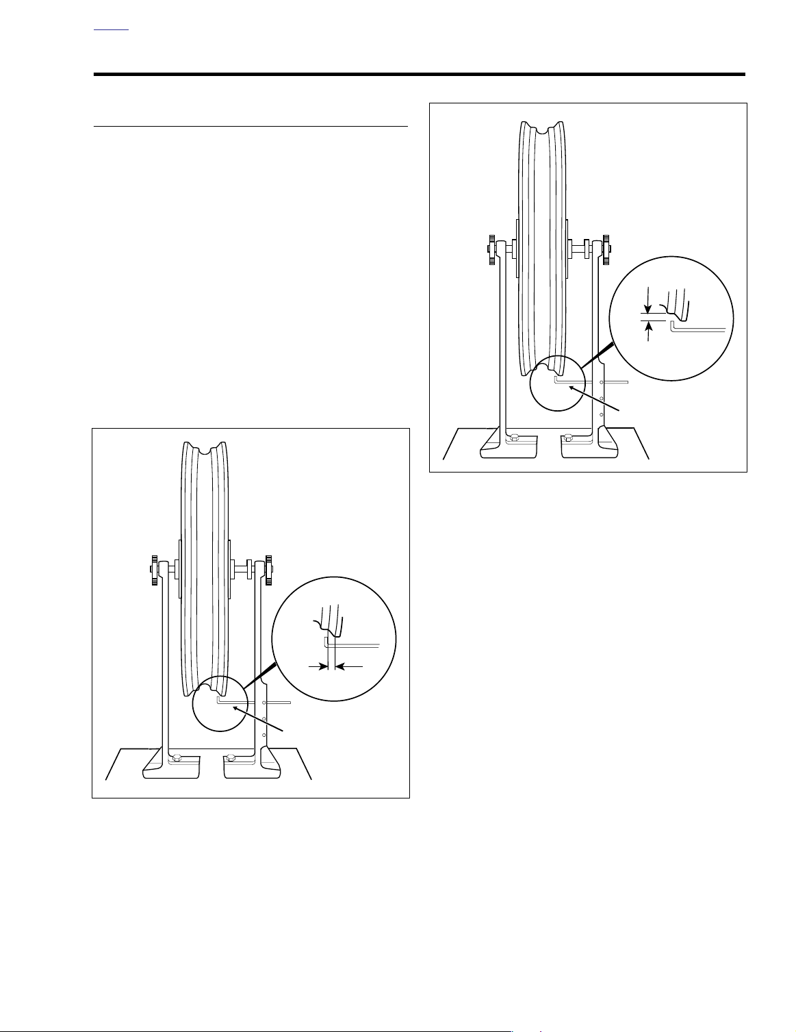
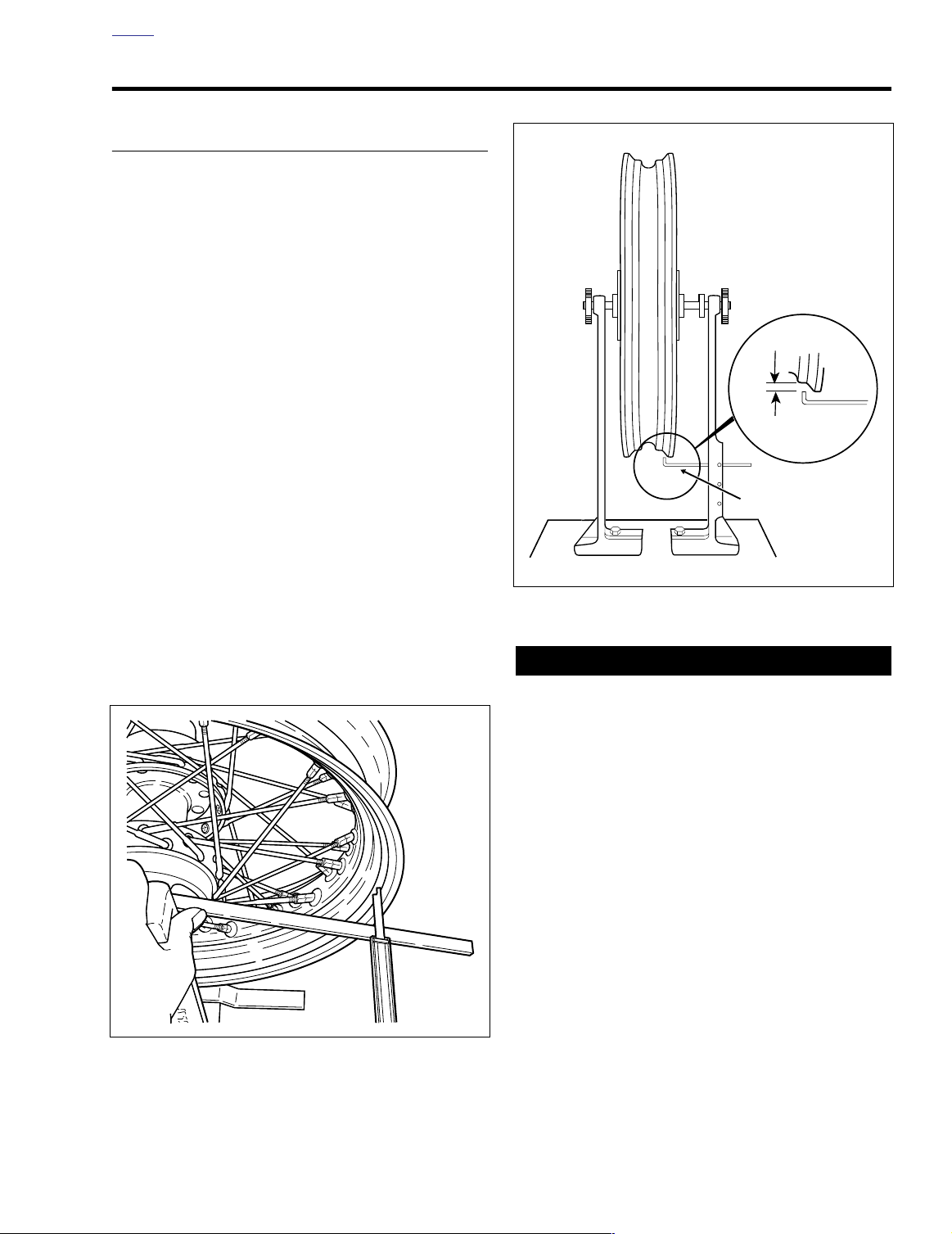
CHECKING RIM RUNOUT 2.5
INSPECTION
Check wheels for lateral and radial runout before installing a
new tire or tube.
1. Install truing arbor in wheel hub and place wheel in
WHEEL TRUING STAND, Part No. HD-99500-80.
2. See Figure 2-15. To check rim lateral runout, place a
gauge rod or dial indicator near the rim bead. If lateral
runout exceeds 0.040 inch (1.02 mm), replace the wheel
if cast. Retrue the wheel if laced.
3. See Figure 2-16. Check the rim radial runout as shown.
If radial runout exceeds 0.030 inch (0.76 mm), replace
the wheel if cast. Retrue the wheel if laced.
NOTE
Rim lateral and radial runout is adjustable on laced wheels.
See Section 2.7 TRUING LACED WHEEL.
f1378x2x
Lateral
Runout
Gauge
Figure 2-15. Checking Rim Lateral Runout
Figure 2-16. Checking Rim Radial Runout
4. If working with a laced wheel, proceed to Section 2.7
TRUING LACED WHEEL to check the wheel offset
dimension.
2004 Touring: Chassis 2-17
Page 18
HOME
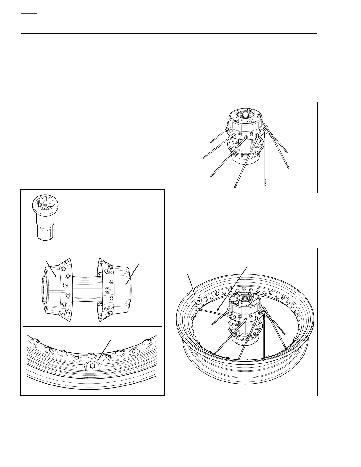
WHEEL LACING - 16 INCH RIM 2.6
GENERAL
The 16 inch wheel uses only one type of spoke, rather than
the separate inner and outer spokes (with differing head
angles) seen in the old style.
Exercise caution to avoid mixing old and new parts. The head
angle of the spoke is closer to 90 degrees, which makes it
very difficult to differentiate from the outer spoke of the old
style.
The nipple fitting of the spoke uses a TORX style fastener
(instead of the straight slotted) and requires a special T-30
I.P. (TORX Plus) driver (HD-42135) for removal and installation. See A of Figure 2-17. Use of a standard T-30 TORX bit
will result in nipple damage.
The 16 inch hub can be easily identified by its aluminum
construction. The 16 inch rim can be quickly identified by the
shape of the flat around the valve stem. The flat is tombstone
shaped on the rim (square shaped on the old style rim). See
B and C of Figure 2-17.
A
f1150a2x
WHEEL LACING
1. If front wheel, place the hub on a table with the wider
flange side up. If rear wheel, place hub so that brake
disc side is up. Insert a spoke in each hole of the lower
row as shown below. Angle the spokes in a clockwise
direction .
f1150d2x
Figure 2-18.
2. Place the rim on the table with the valve stem side up.
Using any lower row spoke, place the first spoke into the
rim hole to the left of the valve stem hole on the upper
half of the rim centerline.
Narrow Flange
Belt Sprocket Side
f1150c2x
Figure 2-17. Parts Identification
B
Valve Stem Flat
Tombstone Shaped
C
Wide Flange
f1150b2x
First
Lower Row Spoke
Valve Stem Hole
f1150e2x
Figure 2-19.
2-18 2004 Touring: Chassis
Page 19
HOME
f1150h2x
f1150i2x
First
Lower Row Spoke
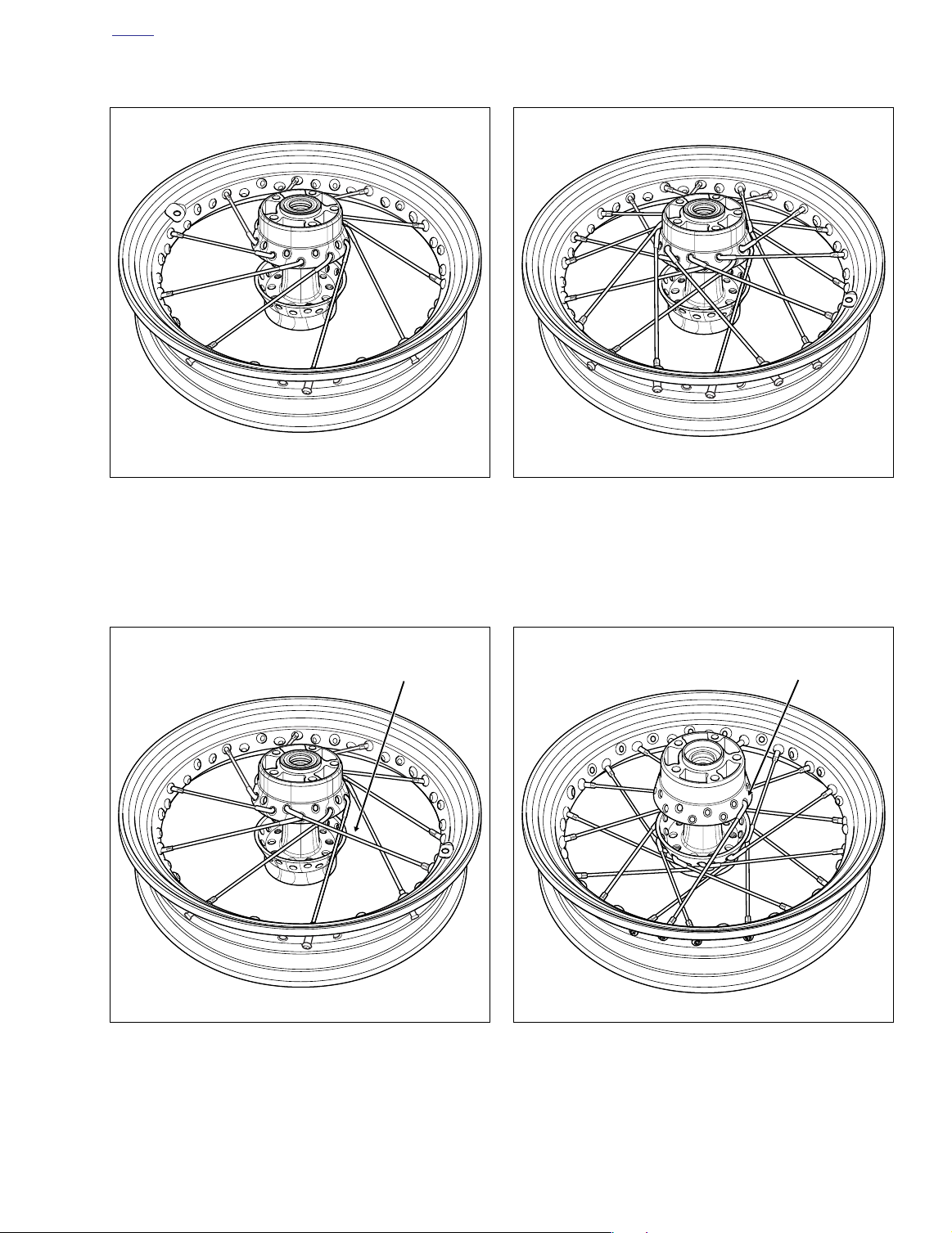
3. Install the rest of the lower row spokes in every fourth
hole.
f1150f2x
Figure 2-20.
5. Install the nine remaining upper row spokes into every
fourth hole remaining above the rim centerline.
Figure 2-22.
4. Place the first upper row spoke into the hub as shown
below. Angle the spoke counterclockwise crossing four
lower row spokes. The spoke must enter the hole to the
left of the valve stem hole.
First
Upper Row Spoke
1
2
4
3
f1150g2x
6. Turn the wheel over. Place any lower row spoke into the
hub. Angle the spoke clockwise and place into rim hole
angled to accept it.
Figure 2-21.
Figure 2-23.
2004 Touring: Chassis 2-19
Page 20
HOME
7. Angled clockwise, place the nine remaining lower row
spokes into hub and rim.
f1150j2x
Figure 2-24.
9. Install the nine remaining upper row spokes into hub and
rim.
f1150l2x
Figure 2-26.
8. Insert any upper row spoke into the hub and angle spoke
counterclockwise. Place spoke into appropriate rim hole
crossing four lower row spokes.
First
Upper Row Spoke
4
1
3
2
f1150k2x
Figure 2-25.
CAUTION
The hub is made of aluminum alloy and should not be
clamped in a vise or gripped with pliers, or the hub material may be damaged.
10. Verify that wheel is true. See Section 2.7 TRUING
LACED WHEEL for truing procedure and spoke torque
specification.
SPOKE TIGHTNESS
At the 1000 mile (1600 km) service interval, the 5000 mile
(8000 km) service interval, and then every 15,000 mile
(24,000 km) service interval thereafter, inspect spoke tightness, if applicable. Proceed as follows:
1. Raise wheel off the ground.
CAUTION
If nipples require more than one full turn to tighten
spoke, remove tire to check that spoke protrusion has
not damaged tube.
2. Lightly tap each spoke with a spoke wrench. Loose
spokes will sound dull and must be tightened. Tighten
spokes to 40-50 in-lbs (4.5-5.6 Nm). If more than a few
spokes are loose, true the entire wheel following the procedure on the next page.
2-20 2004 Touring: Chassis
Page 21
HOME
CAUTION
f1379x2x
Gauge
Radial
Runout
TRUING LACED WHEEL 2.7
PROCEDURE
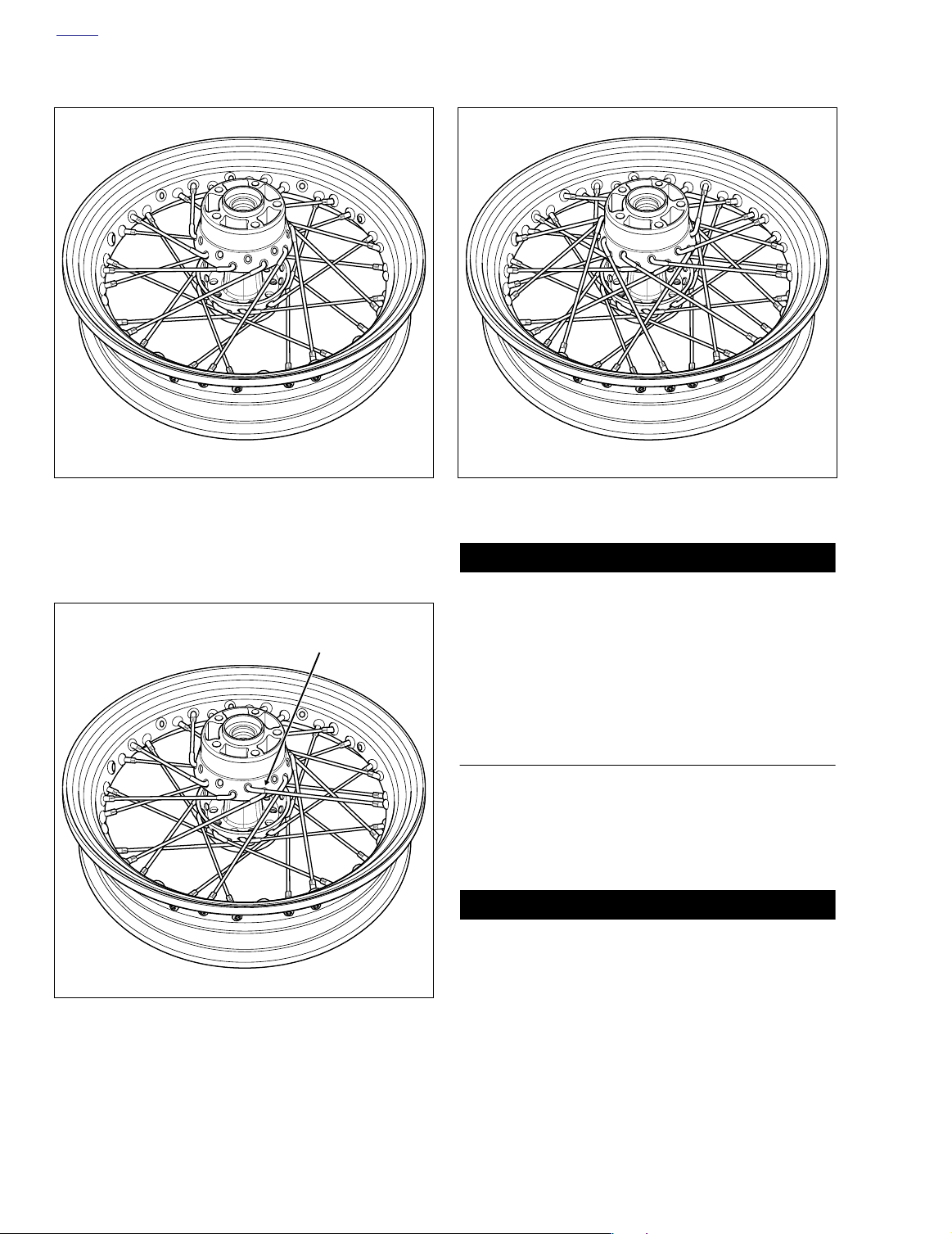
1. Divide the wheel spokes into ten groups of four and
mark the center of each group with a piece of tape. The
groups should be directly across from one another and
approximately 90
four groups finger tight, leaving all others loose.
2. See Figure 2-28. Install truing arbor in wheel hub and
place wheel in WHEEL TRUING STAND, Part No. HD99500-80. Tighten arbor nuts so hub will turn on its bearings.
3. Lay a straightedge across the hub brake disc flange
(valve stem side of dual disc front wheel) and one of the
marked spoke groups. Measure the distance from the
straightedge to the edge of the rim as shown in Figure 2-
27. Be sure to subtract the thickness of the straightedge.
The offset dimension must be as follows:
● Front Wheel: 1.555- 1.575 inches (39.5- 40.0 mm).
● Rear Wheel: 1.472- 1.492 inches (37.4- 37.9 mm).
ο
apart. Tighten the spokes in these
If the dimension is not correct, tighten the four spokes
accordingly. Use the special T-30 I.P. (TORX Plus) driver
(HD-42135). For example, If the measurement on the right
rim edge side is less than it should be, loosen the two spokes
attached to the hub right side and tighten the two spokes
attached to the hub left side. Turn all four spokes an equal
number of turns until offset dimension is correct.
f1155b2x
Figure 2-28. Truing Rim Radially
Always loosen the appropriate spokes before tightening
the other two. Reversing this procedure will cause the
rim to become out-of-round.
4. Repeat Step 3 for all four groups on the wheel.
5. See Figure 2-28. After rim has been trued sideways it
must be checked and trued radially. Adjust truing stand
gauge to the rim's tire bead seat as shown. The rim
should be trued within 1/32 inch (0.79 mm).
6. Spin the rim slowly. If the rim contacts the gauge on or
near a marked group of spokes, loosen the spokes in the
marked group on the opposite side of the rim. Now
tighten the spokes in the group where the rim makes
contact. Loosen and tighten spokes an equal number of
turns.
7. If the rim contacts the gauge between two marked
groups, loosen the spokes in both opposite groups and
tighten the spoke groups on the side of the rim that
makes contact.Figure 2-27. Checking Laced Hub Offset Dimension
2004 Touring: Chassis 2-21
Page 22

HOME
8. When the wheel is centered and trued, start at the valve
stem hole and tighten the rest of the spoke nipples one
turn at a time until they are snug. Repeat step tightening
each spoke nipple to 40-50 in-lbs (4.5-5.6 Nm).
11WARNING1WARNING
Do not tighten spokes too tight, or nipples may be drawn
through rim, or hub flanges may be distorted. If spokes
are left too loose, they will continue to loosen when
wheel is put into service. This could adversely affect
handling, or cause spoke breakage, possibly leading to
loss of vehicle control, which could result in death or
serious injury.
9. File or grind off ends of spokes protruding through nipples to prevent puncturing tube when tire is mounted.
10. Check the rim lateral and radial runout as described
under Section 2.5 CHECKING RIM RUNOUT.
NOTE
After installation of front wheel, visually check the relationship of the front wheel to the fork fender bosses. The front
wheel should be approximately centered between the
bosses.
2-22 2004 Touring: Chassis
Page 23
HOME
1634
TIRES AND TUBES 2.8
GENERAL
Tires should be inspected for punctures, cuts, breaks and
wear at least weekly.
Whenever a tube type tire is replaced, the tube should also
be replaced. Inner tubes should be patched only as an emergency measure. Replace a damaged tube as soon as possible. Inner tubes must be used on all Harley-Davidson laced
wheels.
11WARNING1WARNING
Excessively worn tires are more susceptible to penetrations. Always remove tires from service before they
reach the tread wear indicator bars, which indicates that
1/32 inch (0.79 mm) tread pattern depth remains. Worn/
unworn tire combinations and worn tires used in wet
conditions can ad-versely affect handling and lead to
loss of vehicle control, which could result in death or
serious injury.
11WARNING1WARNING
Tubeless tires may be repaired in the tread area only and
then the puncture must be 1/4 inch (6.4 mm) or smaller.
Never repair a tire with less than 1/16 inch (1.6 mm) tread
depth. All repairs must be made from inside the tire. Use
of faulty or defective tires can adversely affect handling
and lead to loss of vehicle control, which could result in
death or serious injury.
NOTE
Acceptable repair methods include a patch and plug combination, chemical or hot vulcanizing patches or head-type
plugs.
When repairing tubeless tires, use TIRE SPREADER, Part
No. HD-21000 to spread the tire sidewalls.
11WARNING1WARNING
Always check both tire sidewalls for arrows indicating
proper forward tire rotation. Some tires require different
tire rotation depending on whether tire is used on front
or rear wheel. Improper mounting can result in poor tire
mileage. In wet weather, improper mounting can adversely affect handling and lead to loss of vehicle control, which could result in death or serious injury.
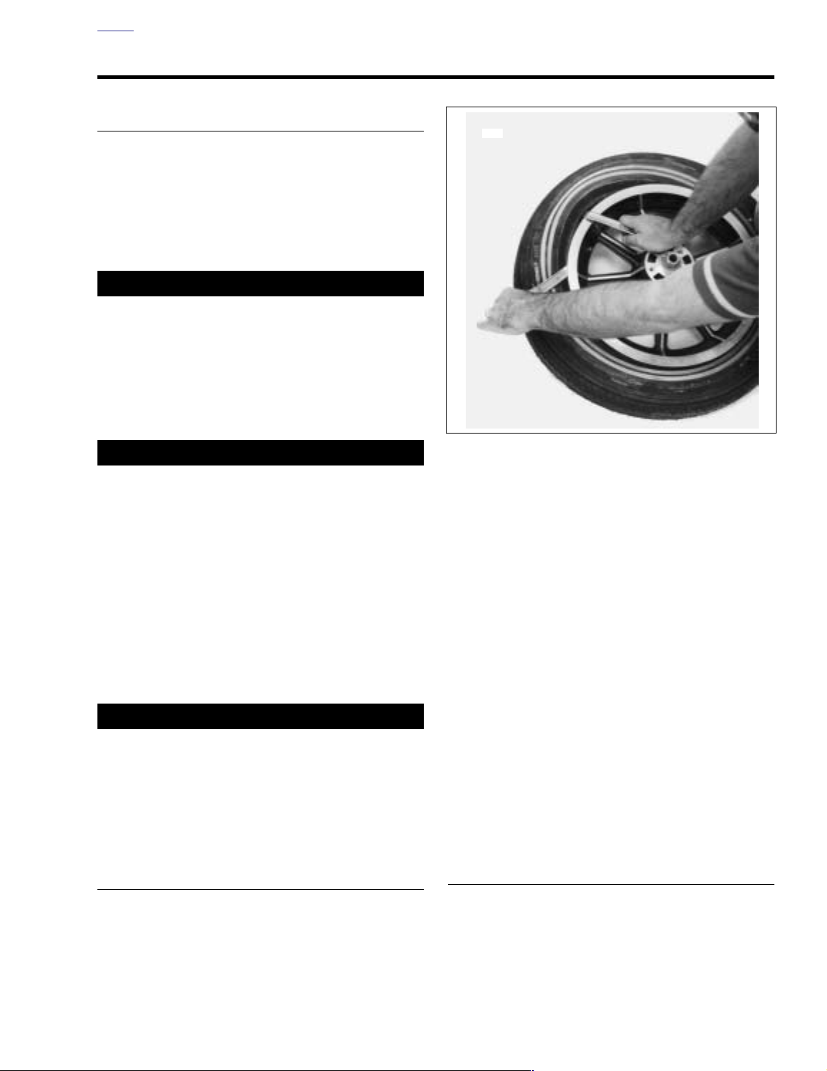
Figure 2-29. Starting Bead Off Rim
2. Loosen both tire beads from rim flange. See Figure 2-29.
In most cases, a bead breaker machine will be required
to loosen the bead from the rim.
3. Using tire tools (not sharp instruments), and RIM PROTECTORS, Part No. HD-01289, start upper bead over
edge of rim at valve. Do not use excessive force when
starting bead over rim. Bead wires may be damaged
ruining the tire. Repeat all around rim until first bead is
over rim. Remove the tube.
NOTE
It is not necessary to use tools to remove tubeless tires.
Make sure beads are well lubricated before removing from
rim.
4. Push lower bead into rim well on one side and insert tire
tool underneath bead from opposite side. Pry bead over
rim edge. Remove tire from rim.
NOTE
It is not always necessary to completely remove tire from rim.
Removing one side allows the tube to be replaced and allows
for inspection of tire.
REMOVAL
1. Remove wheel from motorcycle. Let the air out of the
tube or tire.
CLEANING AND INSPECTION
1. Clean the inside of tire, rim and tube. If rim is dirty or
rusty, clean with a stiff wire brush.
2004 Touring: Chassis 2-23
Page 24
HOME
Indicator
Ring
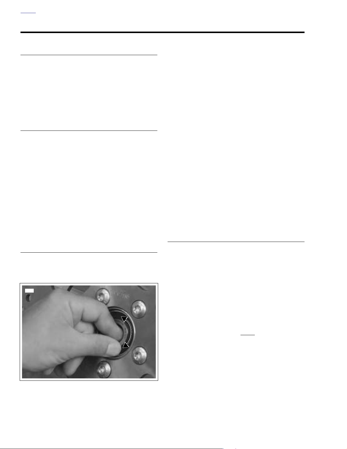
Figure 2-30. Snap-in Tubeless Tire Valves
2. Inspect the tire and tube for wear.
1635
INSTALLATION
11WARNING1WARNING
Use the correct inner tube and tire. See TIRE DATA in
SPECIFICATIONS. Use of incorrect tires or tubes can
adversely affect handling or result in tire failure, which
could result in death or serious injury.
11WARNING1WARNING
Do not interchange tire valves from one type to another.
Always replace valves with the same type as originally
furnished, either the threaded valve stem or snap-in
type. The rim configuration is designed to fit one type
only. Use of the wrong valve can lead to tire failure,
which could result in death or serious injury.
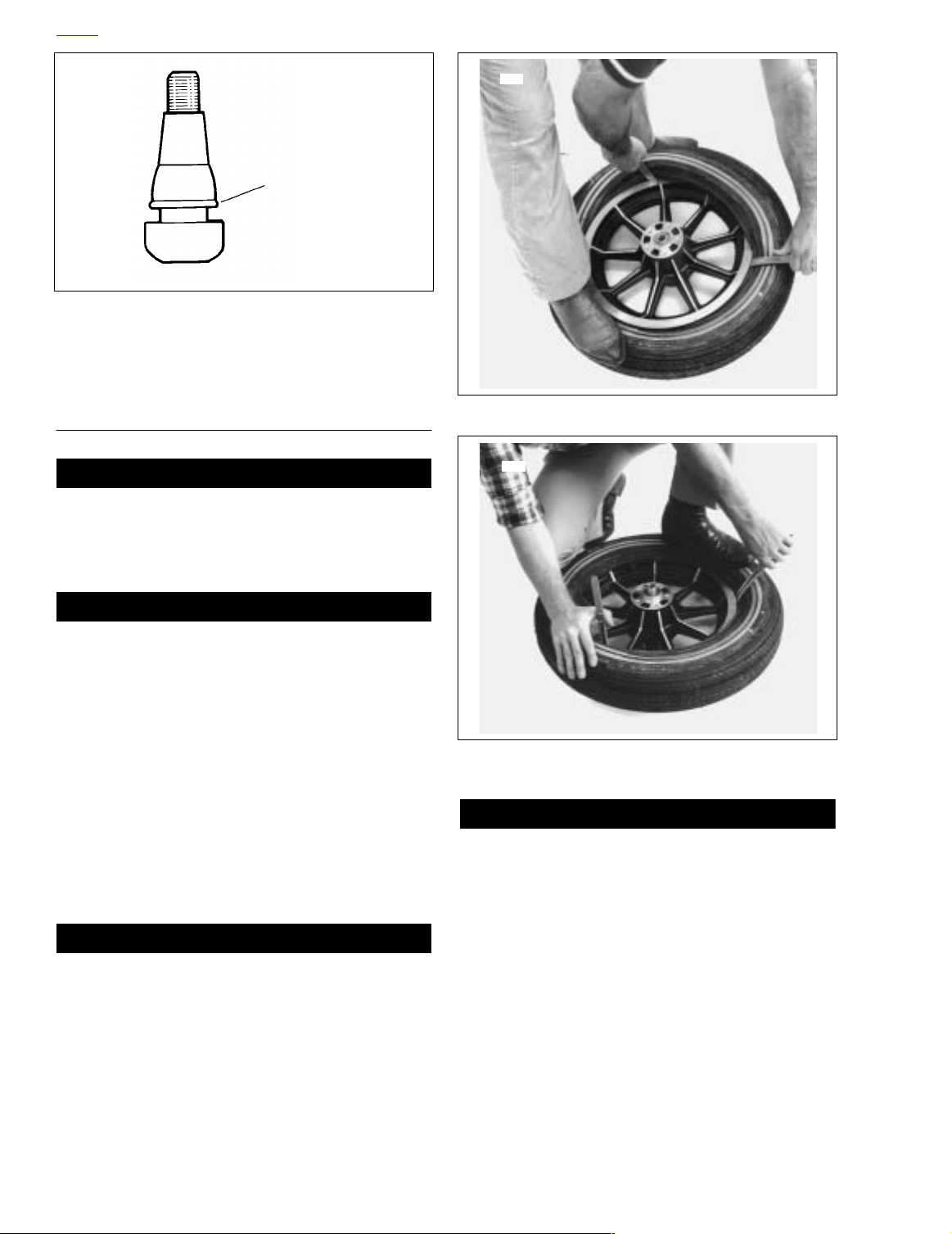
1. On tubeless wheels, damaged or leaking valves must be
replaced. To replace a snap-in type valve proceed as follows:
a. See Figure 2-30. Moisten the valve with water and
insert valve stem through rim hole.
b. Thread plug tool on valve stem and pull valve
through rim until all of the indicator ring is visible.
11WARNING1WARNING
Only install original equipment tire valves and valve
caps. A valve, or valve and cap combination, that is too
long may strike adjacent components, damage the valve
and cause rapid tire deflation. Rapid tire deflation can
cause loss of vehicle control, which could result in death
or serious injury.
Figure 2-31. Starting Bead on Rim
1636
Figure 2-32. Starting Second Bead on Rim
11WARNING1WARNING
Aftermarket valve caps that are heavier than the original
equipment cap may have clearance at slow speeds, but
at high speed the valve/cap will be moved outward by
centrifugal force. This movement could cause the valve/
cap to strike adjacent components, damage the valve
and cause rapid tire deflation. Rapid tire deflation can
cause loss of vehicle control, which could result in death
or serious injury.
2. On laced wheels, install a rim strip into the rim well.
Make sure no spokes protrude through nipples and be
sure to align the valve stem hole in rim strip with hole in
rim.
2-24 2004 Touring: Chassis
Page 25

HOME
f1386b2x
Gauge
Tire Radial Runout
f1386a2x
Gauge
Tire Lateral
Runout
3. Thoroughly lubricate the rim flanges and both beads of
the tire with tire lubricant. Install RIM PROTECTORS,
Part No. HD-01289 to prevent scarring rims.
4. See Figure 2-31. Starting at the valve stem, start the first
bead into the rim well. Work the bead on as far as possible by hand. Use the tire tool to pry the remaining bead
over the rim flange. If tire has colored dot on sidewall, it
is a balance mark and should be located next to valve
stem hole.
5. Inflate tube just enough to round it out. Lubricate thoroughly 360˚ around the tube base. Insert tube in tire with
valve stem in hole.
6. See Figure 2-32. Starting 180˚ from valve stem, start the
second bead onto the rim. Work the bead onto the rim
with tire tools, working toward valve in both directions.
Remove the valve core from the rim hole before prying
the remaining bead over the rim flange.
Make sure inner tube valve stem moves in and out freely,
then inflate the tire to recommended pressure to seat the
bead. See TIRE DATA at the beginning of this section.
Then deflate tire to allow inner tube to smooth out.
Inflate again to recommended pressure to seat the
bead.
7. Use the BEAD EXPANDER (Part No. HD-28700) to seat
beads on tubeless tires.
Figure 2-33. Checking Tire Radial Runout
11WARNING1WARNING
Do not inflate tire over 40 psi (2.8 bars) to seat beads.
Inflating tire beyond this point can cause the tire rim
assembly to burst, which could result in death or serious
injury. If the beads fail to seat, deflate and relubricate the
bead and rim. Reinflate to seat beads, but do not exceed
40 psi (2.8 bars).
CAUTION
When mounting tire and tube on the rim, use extreme
care so the inner tube is not pinched.
Checking Tire Radial Runout
1. Check runout by turning wheel on axle, measuring
amount of radial displacement from a fixed point near
the tire. See Figure 2-33.
2. Tire tread runout should be no more than 0.090 inch
(2.28 mm) If tire tread runout exceeds this specification,
remove tire from rim and check rim runout to see if rim is
at fault. (See Section 2.5 CHECKING RIM RUNOUT).
Make sure bead is properly seated on rim. Deflate and reseat
tire if necessary.
3. If rim runout is less than 1/32 inch (0.79 mm), tire is at
fault and should be replaced. If rim runout exceeds this
specification, correct by replacing cast wheel or truing
laced wheel.
NOTE
Figure 2-34. Checking Tire Lateral Runout
Checking Tire Lateral Runout
1. Check runout by turning wheel on axle, measuring tread
runout. See Figure 2-34.
2. Tire tread runout should be no more than 0.080 inch
(2.03 mm). If tire tread runout exceeds this specification, remove tire from rim and check rim bead runout to
see if rim is at fault (see Section 2.5 CHECKING RIM
RUNOUT).
NOTE
Make sure bead is properly seated on rim. Deflate and reseat
tire if necessary.
2004 Touring: Chassis 2-25
Page 26

HOME
3. If rim bead runout is less than 1/32 inch (0.79 mm), tire
is at fault and should be replaced. If rim bead runout
exceeds this specification, correct by replacing cast
wheel or truing laced wheel.
Wheel Balancing
Wheel balancing is recommended to improve handling and
reduce vibration, especially at high road speeds. Cast aluminum wheels require special self-adhesive weights. Gold
Color – 1 oz. (28g) weight, 1/2 oz. (14g) weight, Silver Color
1/2 oz. (14g) and 1/4 oz. (7g), and Black 1/4 oz. (7g) weight.
Laced wheels use balance weights which press over the
spoke nipples. 1 oz. (28g), 3/4 oz. (21g) and 1/2 oz. (14g)
weights are available.
1. Self adhesive wheel weights should be applied to the flat
surface of the rim. Make sure that area of application is
completely clean, dry and free of oil and grease.
NOTE
If 1 oz. (28g) or more weight must be added at one location,
split the amount so that half is applied to each side of the rim.
2. Remove paper backing from weight and apply three
drops of Loctite SUPERBONDER 420 to the adhe-
sive side of the weight. Place the weight on rim, press
firmly in place and hold for 10 seconds. Full adhesive
cure takes 8 hours.
3. In most cases, static balancing using WHEEL TRUING
STAND, Part No. HD-99500-80, will produce satisfactory
results. However, dynamic balancing, utilizing a wheel
spinner, should be used to produce finer tolerances for
best high and low speed handling characteristics. Follow
the instructions supplied with the balance machine you
are using. Wheels should be balanced to within 1/2 oz.
(14g) at 60 mph (96 km/h). The maximum permissible
weight to accomplish balance is 3-1/2 oz. (99g) total.
2-26 2004 Touring: Chassis
Page 27

HOME
f2117x2x
f2118x2x
Alignment
Screw
Pilot
Alignment
Fixture
VEHICLE ALIGNMENT 2.9
11WARNING1WARNING
Vehicle alignment is very important to ensure proper
handling and vibration control. Follow this procedure
carefully and in the sequence given. Failure to do so may
lead to loss of vehicle control, which could result in
death or serious injury.
METHOD A
NOTE
Use this procedure to realign the powertrain to the frame
whenever major disassembly or engine replacement occurs.
For acceptable results, a careful inspection should be
performed (wheel and tire runout, laced wheel offset, rubber
mount condition, etc.) to ensure that it is conducted with
serviceable components. See INSPECTION for more infor-
mation.
1. Place the motorcycle on a hydraulic center stand or
place blocking under the frame to support the vehicle
and lift the rear wheel off the ground. Be sure the motorcycle is positioned as level as possible.
2. Remove socket screw with lockwasher to remove left
passenger footboard from rear swingarm bracket.
Tighten both rear swingarm bracket bolts to 34-42 ft-lbs
(46-57 Nm). Repeat step on right side of motorcycle.
3. Remove the decorative chrome plug from both rear
swingarm brackets. While holding the left side pivot shaft
locknut, tighten the right side locknut to 40-45 ft-lbs (5461 Nm). Then hold the right side pivot shaft locknut and
tighten the left side locknut to 40-45 ft-lbs (54-61 Nm).
4. Verify that belt deflection is within specification and that
adjuster cams are tight against rear swingarm weld
nubs. Holding
nut on right side to 95-105 ft-lbs (128.8-142.4 Nm).
5. Remove seat. See Section 2.24 SEAT, REMOVAL.
6. Partially remove fuel tank to gain access to top engine
mounting bracket and stabilizer link. See Section 4.7
FUEL TANK (CARBURETED), PA RTIAL REMOVAL,
FLHT/C, or FLHR/S. For fuel injected models, see Sec-
tion 9.4 FUEL TANK (FUEL INJECTED), PA R TIAL
REMOVAL, FLHT/C/U/I, FLTRI, or FLHR/C/S/I.
7. Top Engine Mount:
a. On left side of motorcycle, tighten the two top
engine mounting bracket to front and rear cylinder
head bolts to 35-40 ft-lbs (48-54 Nm). See A of Fig-
ure 2-37.
b. Moving to right side of motorcycle, tighten the top
stabilizer link eyelet to frame weldment bolt to 18-22
ft-lbs (24-30 Nm). See C of Figure 2-37.
weld nut on left side of axle, tighten cone
Figure 2-35. Vehicle Alignment Tool
(Part No. HD-46247)
Figure 2-36. Install Vehicle Alignment Tool (Left Side)
c. Loosen both top stabilizer link jam nuts.
d. Remove the top stabilizer link eyelet to top engine
mounting bracket bolt. See B of Figure 2-37.
8. Front Engine Mount:
a. Remove flange locknuts from studs on lower frame
crossmember. Remove voltage regulator from studs
and allow to hang by cables at front of motorcycle.
b. Tighten two engine to front engine mounting bracket
bolts to 33-38 ft-lbs (45-52 Nm). See H of Figure 2-
37.
c. Tighten front stabilizer link eyelet bolt to block on
front engine mounting bracket to 18-22 ft-lbs (24-30
Nm). See E of Figure 2-37.
d. Loosen both front stabilizer link jam nuts.
e. Remove front stabilizer link eyelet to frame weld-
ment bolt. See D of Figure 2-37.
f. Remove the center front engine mounting bracket to
rubber mount bolt (with washers and nut). See F of
Figure 2-37.
2004 Touring: Chassis 2-27
Page 28

HOME
B
C
A
LEFT SIDE RIGHT SIDE
Top Stabilizer Link and Engine Mounting Bracket
f2111x2xf2181x2x
H
Front Engine
Mounting Bracket
T
op
ATop Engine Mounting Bracket to Cylinder Heads
BEyelet to Top Engine Mounting Bracket
CEyelet to Frame Weldment
F
Front Stabilizer Link and Engine Mounting Bracket
Jam Nut
E
D
Front
Stabilizer Link
G
Bottom
DEyelet to Frame Weldment
EEyelet to Front Engine Mounting Bracket
FFront Engine Mounting Bracket to Rubber Mount
GFront Engine Mount to Frame Crossmember
H Engine to Front Engine Mounting Bracket
f1303x2x
Figure 2-37. Engine Mounting Bracket Bolts
9. Obtain Vehicle Alignment Tool (HD-46247). See Figure
2-35. Proceed as follows:
2-28 2004 Touring: Chassis
a. Back off alignment screws and pilot so that no con-
tact is made with pivot shaft during initial installation.
Page 29

HOME
b. Position alignment fixture so that pilot begins to
engage hole in rear swingarm bracket and then
start 5/16 allen head screw (with flat washer) into
lower hole of passenger footboard mount. Leave fixture loosely installed. Repeat step on other side of
motorcycle.
NOTE
Alignment fixtures are stamped L(eft) and R(ight) for easy
identification. When installing alignment fixture on right side
of motorcycle, first remove hex screw to free brake hose Pclamp from rear swingarm bracket. The relief in right side fixture accommodates hex screw boss.
c. Holding alignment fixture tight against rear swing-
arm bracket, use knurling to rotate pilot until it bottoms in rear swingarm bracket. Without disturbing
setting of pilot, tighten allen head screw to passenger footboard mount to 18-22 ft-lbs (24-30 Nm).
Repeat step on other side of motorcycle.
d. Hand turn alignment screw until it bottoms against
end of pivot shaft. Repeat step on other side of
motorcycle.
e. Tighten alignment screw to 60-80 in-lbs (6.8-9.0
Nm). Repeat step on other side of motorcycle. See
Figure 2-36.
10. Adjust each stabilizer link as follows:
a. Install bolts removed under steps 7(d) and 8(e), and
using the center hex to maintain equal thread
engagement at both eyelets, adjust stabilizer links
so that bolts thread in without any stress or engine
movement. See B and D of Figure 2-37.
b. Alternately tighten bolts to 18-22 ft-lbs (24-30 Nm).
c. Holding the stabilizer link adjuster and mounting
eyelets to prevent movement or binding, tighten jam
nuts on top and front stabilizer links.
11. Remove vehicle alignment tool from rear swingarm
brackets.
12. Snap the chrome plugs back into the rear swingarm
brackets.
13. Install socket screw with lockwasher to fasten passenger
footboard to rear swingarm bracket. Tighten screw to 1518 ft-lbs (20-24 Nm). Repeat step on other side of
motorcycle.
14. Verify that front rubber mount is centered under the front
mounting plate bolt hole and has not been bound by the
plate dragging across the isolator.
a. If the front rubber mount is centered and free of
binding, proceed as follows:
•Tighten the two front engine mount to frame cross-
member bolts to 15-20 ft-lbs (20-27 Nm). See G of
Figure 2-37.
•Install center front engine mounting bracket to rub-
ber mount bolt (with washers and nut) and tighten to
15-20 ft-lbs (20-27 Nm). See F of Figure 2-37.
b. If centering or relaxation of the mount is required,
proceed as follows:
• Loosen the two front engine mount to frame crossmember bolts. See G of Figure 2-37.
• Push on the rubber mount to center it with the thru
bolt hole in the mounting plate. It may be necessary
to bounce or wiggle the engine to unload any
binding of the rubber mount on the mounting plate.
•After the mount is centered, tighten the two front
engine mount to frame crossmember bolts to 15-20
ft-lbs (20-27 Nm). See G of Figure 2-37.
•Install center front engine mounting bracket to rubber mount bolt (with washers and nut) and tighten to
15-20 ft-lbs (20-27 Nm). See F of Figure 2-37.
15. Slide voltage regulator over studs on lower frame crossmember at front of vehicle. Install flange locknuts on
studs and tighten to 70-100 in-lbs (7.9-11.3 Nm).
16. Install fuel tank. For carbureted models, see Section 4.7
FUEL TANK (CARBURETED), INSTALLATION (AFTER
PA RTIAL REMOVAL), FLHT/C, or FLHR/S. For fuel
injected models, see Section 9.4 FUEL TANK (FUEL
INJECTED), INSTALLATION (AFTER PARTIAL
REMOVAL), FLHT/C/U/I, FLTRI, or FLHR/C/S/I.
17. Verify minim
the following frame mounted components:
a. Top Engine/Horn Mounting Bracket to Fuel Tank:
0.328 inch (8.3 mm).
b. Rocker Covers to Fuel Tank: 0.375 inch (9.5 mm).
c. Carburetor Top Cover to Fuel Tank: 0.375 inch (9.5
mm).
d. Rear Spark Plug Boot to Fuel Valve: 0.250 inch (6.4
mm).
e. To p Stabilizer Link to Induction Module: 0.375 inch
(9.5 mm).
f. Front Stabilizer Link to Voltage Regulator: 0.375
inch (9.5 mm).
g. Inner Primary Chaincase to Lower Frame Tube:
0.187 inch (4.8 mm).
h. Exhaust Crossover Pipe to Primary Housing: 0.125
inch (3.2 mm).
i. Tire to Rear Fender: 0.100 inch (2.5 mm).
j. Perform the procedure under Method B to trouble-
shoot clearance problems and to identify offending
component(s).
18. Install seat. See Section 2.24 SEAT, INSTALLATION.
19. Test ride the motorcycle.
Vehicle leads that require more than 2-lbs pull to correct
need further diagnosis. Perform the procedure under Method
B in this section.
um clearance between the powertrain and
NOTE
2004 Touring: Chassis 2-29
Page 30

HOME
METHOD B
NOTE
Use this procedure to determine the cause of vehicle misalignment and to locate clearance problems, or as an
alternative to use of the Vehicle Alignment Tool (HD-46247)
described under Method A. For acceptable results, a careful
inspection should be performed (wheel and tire runout, laced
wheel offset, rubber mount condition, etc.) to ensure that it is
conducted with serviceable components. See INSPECTION
for more information.
1. Place the motorcycle on a hydraulic center stand or
place blocking under the frame to support the vehicle
and lift the rear wheel off the ground. Be sure the motorcycle is positioned as level as possible.
2. Remove socket screw with lockwasher to remove left
passenger footboard from rear swingarm bracket.
Tighten both rear swingarm bracket bolts to 34-42 ft-lbs
(46-57 Nm). Repeat step on right side of motorcycle.
3. Remove the decorative chrome plug from both rear
swingarm brackets. While holding the left side pivot shaft
locknut, tighten the right side locknut to 40-45 ft-lbs (5461 Nm). Then hold the right side pivot shaft locknut and
tighten the left side locknut to 40-45 ft-lbs (54-61 Nm).
4. Verify that belt deflection is within specification and that
adjuster cams are tight against rear swingarm weld
nubs. Holding
nut on right side to 95-105 ft-lbs (128.8-142.4 Nm).
5. Remove seat. See Section 2.24 SEAT, REMOVAL.
6. Partially remove fuel tank to gain access to top engine
mounting bracket and stabilizer link. See Section 4.7
FUEL TANK (CARBURETED), PA RTIAL REMOVAL,
FLHT/C, or FLHR/S. For fuel injected models, see Sec-
tion 9.4 FUEL TANK (FUEL INJECTED), PA R TIAL
REMOVAL, FLHT/C/U/I, FLTRI, or FLHR/C/S/I.
7. Top Engine Mount:
a. On left side of motorcycle, tighten the two top
engine mounting bracket to front and rear cylinder
head bolts to 35-40 ft-lbs (48-54 Nm). See A of Fig-
ure 2-37.
b. Moving to right side of motorcycle, tighten the top
stabilizer link eyelet to frame weldment bolt to 18-22
ft-lbs (24-30 Nm). See C of Figure 2-37.
c. Loosen both top stabilizer link jam nuts.
d. Remove the top stabilizer link eyelet to top engine
mounting bracket bolt. See B of Figure 2-37.
8. Front Engine Mount:
a. Remove flange locknuts from studs on lower frame
crossmember. Remove voltage regulator from studs
and allow to hang by cables at front of motorcycle.
b. Tighten two engine to front engine mounting bracket
bolts to 33-38 ft-lbs (45-52 Nm). See H of Figure 2-
37.
weld nut on left side of axle, tighten cone
c. Tighten front stabilizer link eyelet to frame weldment
bolt to 18-22 ft-lbs (24-30 Nm). See D of Figure 2-
37.
d. Tighten front stabilizer link eyelet bolt to block on
front engine mounting bracket to 18-22 ft-lbs (24-30
Nm). See E of Figure 2-37.
e. Remove the center front engine mounting bracket to
rubber mount bolt (with washers and nut). See F of
Figure 2-37.
9. To verify alignment, install alignment bars or other suitable device on both the left and right side of motorcycle.
Proceed as follows:
NOTE
If the front tire is wider than the rear, then the alignment bars
must either be shimmed out equally at the points of contact
on the rear tire, notched at the front to clear the front tire, or
attached to the front tire with all measurements performed at
the rear. For explanatory purposes, the following procedure
assumes the alignment bars are secured to the rear tire.
a. Place a set of straightedges on both the left and
right sides of the motorcycle alongside the front and
rear tires.
b. Ve rify that both alignment bars firmly contact the
rear wheel at two points. Use clamp or bungee
cords to hold the bars in place. Tension should be
equal to avoid spreading or pinching the bars.
c. Verify that the bars are straight by matching the
width measurements at both ends.
d. Straighten the front end and verify that the
measurements from the front wheel to the bar on
one side of the motorcycle are equal at two points,
both fore and aft.
e. Measure the front wheel to the bar on the other side
of the motorcycle, both fore and aft, and compare
the results to the measurements obtained under
step 9(d). Measurements from left to right should be
equal +/- 0.030 inch (0.76 mm).
f. Loosen jam nuts, and using the center hex, adjust
the front stabilizer link as required to obtain equal
measurements at all four points (+/- 0.030 inch or
0.76 mm). See Figure 2-38.
NOTE
After each adjustment, unload any binding of the front rubber
mount and verify that the alignment bars and front wheel are
still correctly positioned.
g. Holding the front stabilizer link adjuster and
mounting eyelets to prevent movement or binding,
tighten both jam nuts.
h. Verify that the front rubber mount is centered under
the thru bolt hole in the mounting plate.
2-30 2004 Touring: Chassis
Page 31

HOME
FLT0240
To Correct:
Adjust top stablizer link.
Chassis
Powertrain
Chassis
Powertrain
To Correct:
Adjust front stablizer link.
FLT0239
Figure 2-38. Horizontally Misaligned
i. If the front rubber mount is centered and free of
binding, proceed as follows:
•Tighten the two front engine mount to frame crossmember bolts to 15-20 ft-lbs (20-27 Nm). See G of
Figure 2-37.
•Install center front engine mounting bracket to rubber mount bolt (with washers and nut) and tighten to
15-20 ft-lbs (20-27 Nm). See F of Figure 2-37.
j. If centering or relaxation of the mount is required,
proceed as follows:
•Loosen the two front engine mount to frame crossmember bolts. See G of Figure 2-37.
• Push on the rubber mount to center it with the thru
bolt hole in the mounting plate. It may be necessary
to bounce or wiggle the engine to unload any
binding of the rubber mount on the mounting plate.
•After the mount is centered, tighten the two front
engine mount to frame crossmember bolts to 15-20
ft-lbs (20-27 Nm). See G of Figure 2-37.
•Install center front engine mounting bracket to rubber mount bolt (with washers and nut) and tighten to
15-20 ft-lbs (20-27 Nm). See F of Figure 2-37.
10. Slide voltage regulator over studs on lower frame crossmember at front of vehicle. Install flange locknuts on
studs and tighten to 70-100 in-lbs (7.9-11.3 Nm).
11. Adjust the top stabilizer link as follows:
Figure 2-39. Vertically Misaligned
a. Using the center hex to maintain equal thread
engagement at both eyelets, adjust stabilizer link so
that bolt removed under step 7(d) threads in without
any stress or engine movement.
b. Tighten the stabilizer link eyelet to top engine
mounting bracket bolt to 18-22 ft-lbs (24-30 Nm).
See B of Figure 2-37.
c. Holding the top stabilizer link adjuster and mounting
eyelets to prevent movement or binding, tighten
both jam nuts.
12. Lower motorcycle to floor and remove hydraulic center
stand or blocking.
13. After verifying that the motorcycle is level, check vertical
alignment placing an inclinometer on both front and rear
brake rotors. Front and rear lean angles should be equal
+/- 1/2 degree. See Figure 2-39. If vertical alignment
exceeds specification, proceed as follows:
a. Loosen the top stabilizer link eyelet to top engine
mounting bracket bolt. See B of Figure 2-37. Verify
that bolt is unloaded and threads freely in and out of
the mounting bracket hole. If necessary, loosen jam
nuts and adjust stabilizer link to a achieve a free
state. Tighten bolt to 18-22 ft-lbs (24-30 Nm) and
then tighten jam nuts before rechecking vertical
alignment.
b. Look for components that are worn, damaged or out
of specification. See INSPECTION on the next
page.
2004 Touring: Chassis 2-31
Page 32

HOME
14. Remove the alignment bars from both the left and right
side of the motorcycle.
15. Snap the chrome plugs back into the rear swingarm
brackets.
16. Install socket screw with lockwasher to fasten passenger
footboard to rear swingarm bracket. Tighten screw to 1518 ft-lbs (20-24 Nm). Repeat step on other side of
motorcycle.
17. Install fuel tank. For carbureted models, see Section 4.7
FUEL TANK (CARBURETED), INSTALLATION (AFTER
PA RTIAL REMOVAL), FLHT/C, or FLHR/S. For fuel
injected models, see Section 9.4 FUEL TANK (FUEL
INJECTED), INSTALLATION (AFTER PARTIAL
REMOVAL), FLHT/C/U/I, FLTRI, or FLHR/C/S/I.
18. Verify minim
the following frame mounted components:
a. Top Engine/Horn Mounting Bracket to Fuel Tank:
0.328 inch (8.3 mm).
b. Rocker Covers to Fuel Tank: 0.375 inch (9.5 mm).
c. Carburetor Top Cover to Fuel Tank: 0.375 inch (9.5
mm).
d. Rear Spark Plug Boot to Fuel Valve: 0.250 inch (6.4
mm).
e. Top Stabilizer Link to Induction Module: 0.375 inch
(9.5 mm).
f. Front Stabilizer Link to Voltage Regulator: 0.375
inch (9.5 mm).
g. Inner Primary Chaincase to Lower Frame Tube:
0.187 inch (4.8 mm).
h. Exhaust Crossover Pipe to Primary Housing: 0.125
inch (3.2 mm).
i. Tire to Rear Fender: 0.100 inch (2.5 mm).
19. Install seat. See Section 2.24 SEAT, INSTALLATION.
20. Test ride the motorcycle.
Vehicle leads that require more than 2-lbs pull to correct
need further diagnosis. See INSPECTION on this page.
um clearance between the powertrain and
NOTE
INSPECTION
At the 10,000 mile (16,000 km) service interval, and at every
10,000 mile (16,000 km) service interval thereafter, inspect
the engine isolators and stabilizer links. Perform inspection
sooner if any sag in the powertrain is observed or abnormal
handling characteristics/vibrations are experienced.
Front Rubber Mount
1. Verify condition and torque of the mounting hardware.
Visually inspect for wear, damage or improper installation. Replace hardware as necessary.
2. Examine carefully at the bottom of the motorcycle paying
special attention to the area between the large flat metal
washer and the bracket on the frame. There should be a
gap between the mounting plate and the cushion portion
of the rubber mount.
3. Replace the rubber mount if there are any signs of
cracking or shearing.
Rear Swingarm Mounts
1. Verify condition and torque of the mounting hardware.
Visually inspect for wear, damage or improper installation. Replace hardware as necessary.
2. Examine rubber mount to be sure there is no twisting or
binding at the parting line.
Engine Stabilizer Links
1. Verify condition and torque of the mounting hardware.
Visually inspect for wear, damage or improper installation. Replace hardware as necessary.
2. Using flats machined into the stabilizer eyelet, gently
rock the link and check for separation of the molded-in
sleeve. Replace as necessary.
Wear in the link also can be measured with a dial indicator by hand compressing and then releasing the link.
Replace any link that exceeds 0.025 inch (0.64 mm) of
play or wear.
2-32 2004 Touring: Chassis
Page 33

HOME
11WARNING1WARNING
CAUTION
f1284x2x
Dual Disc
Single Disc
Bore Size
Stamp
FRONT BRAKE MASTER CYLINDER 2.10
GENERAL
Master cylinders designed for dual disc (two caliper) operation have an 11/16 inch bore, while those that are designed
for single disc (one caliper) operation have a 9/16 inch bore.
The bore size is stamped on the master cylinder assembly
inboard of the handlebar clamp bracket. See Figure 2-40.
11WARNING1WARNING
Do not use a 9/16 inch bore master cylinder assembly on
dual disc (two caliper) models. Likewise, do not use an
11/16 inch bore master cylinder assembly on single disc
(one caliper) models. These master cylinder assemblies
are not interchangeable. Using the wrong assembly can
adversely affect braking efficiency or result in brake failure, which could result in death or serious injury.
REMOVAL/DISASSEMBLY
1. Remove banjo bolt and two steel/rubber washers to disconnect fitting of hydraulic brake line from master cylinder housing. Hold paper cup or other suitable container
under banjo bolt bore to allow reservoir to drain. Discard
steel/rubber washers.
CAUTION
Do not remove the master cylinder assembly without
first placing the 5/32 inch (4.0 mm) cardboard insert
between the brake lever and lever bracket. Removal without the insert may result in damage to the rubber boot
and plunger of the Front Stoplight Switch.
NOTE
Use the eyelet of a small cable strap if the cardboard insert is
not available.
2. Place the cardboard insert between the brake lever and
lever bracket. See Figure 2-41.
3. Using a T27 TORX drive head, remove two screws with
flat washers to release handlebar clamp from the master
cylinder housing. Remove the clamp and brake lever/
master cylinder assembly from the handlebar. See Fig-
ure 2-42.
4. Remove the cardboard insert (or cable strap eyelet)
between the brake lever and lever bracket.
Figure 2-40. Verify Correct Bore Size Before Use
Always wear proper eye protection when removing retaining rings. Use the correct retaining ring pliers. Verify
that the tips of the pliers are not damaged or excessively
worn. Slippage may propel the ring with enough force to
cause eye injury.
5. Remove retaining ring from pivot pin groove at bottom of
master cylinder bracket. Discard retaining ring.
6. Remove pivot pin and brake hand lever from master cylinder assembly.
7. Carefully remove wiper with pick or similar tool.
8. Remove piston cap.
9. Remove piston with O-ring and primary cup.
10. Remove spring.
To prevent dirt and other contaminants from entering the
master cylinder reservoir, thoroughly clean the cover
before removal.
11. Remove two Phillips screws, cover and cover gasket
from the master cylinder reservoir.
2004 Touring: Chassis 2-33
Page 34

HOME
7959
5/32 Inch
(4.0 mm)
Cardboard
Insert
Figure 2-41. Install Cardboard Insert
Before Removing Master Cylinder Assembly
CLEANING AND INSPECTION
4. Inspect the piston bore in the master cylinder housing for
scoring, pitting or corrosion. Replace the housing if any
of these conditions are found.
5. Inspect the outlet port that mates with the brake line fitting. As a critical sealing surface, replace the housing if
any scratches, dents or other damage is noted.
6. Inspect the cover gasket for cuts, tears or general deterioration. If gasket and/or sight glass replacement is necessary, proceed as follows:
a. From inboard side, push sight glass toward top of
cover until free.
b. Pull rubber gasket from cover.
c. Fit nipple of new gasket into hole of cover aligning
gasket and cover thru holes.
d. From bottom of gasket, push flat end of sight glass
through nipple until top of glass is flush with top of
gasket. Verify that glass is square in bore. If some
lubrication is necessary, use a small quantity of
clean brake fluid.
ASSEMBLY/INSTALLATION
11WARNING1WARNING
Do not use replacement parts from single caliper repair
kits (9/16 inch bore) on dual caliper models. Likewise, do
not use replacement parts from dual caliper repair kits
(11/16 inch bore) on single caliper models. Parts are not
interchangeable. Using the wrong replacement parts can
adversely affect braking efficiency or result in brake failure, which could result in death or serious injury.
1. Always reassemble the master cylinder using new parts
from the correct repair kit.
2. Clean all parts with denatured alcohol or D.O.T. 5
BRAKE FLUID. Do not contaminate with mineral oil or
other solvents. Wipe dry with a clean, lint free cloth.
Blow out drilled passages and bore with a clean air supply. Do not use a wire or similar instrument to clean
drilled passages in bottom of reservoir.
11WARNING1WARNING
Use denatured alcohol to clean brake system components. Do not use mineral base solvents (such as gasoline and paint thinner) or deterioration of rubber parts
may occur after assembly. Deterioration of components
may result in premature brake failure, which could result
in death or serious injury.
3. Carefully inspect all parts for wear or damage and
replace as necessary.
1. Fit O-ring into groove on outboard side of piston (pin
side). See Figure 2-42.
2. Fit primary cup over lip on inboard side of piston, so that
closed side (smaller OD) contacts shoulder.
3. Coat piston bore of master cylinder reservoir with special lubricant supplied in the service parts kit. Also apply
the lubricant to OD of installed O-ring and primary cup.
4. Insert metal retainer end of spring into piston bore, so
that it seats against counterbore (recess) at bottom.
5. Slide piston over spring.
6. Fit wiper over piston cap so that flat side of wiper contacts cap shoulder.
7. Fit piston cap over piston pin.
8. Press down on wiper until it contacts the counterbore.
Larger OD of wiper must be completely seated in groove
on outlet side of piston bore.
9. Note that the angular shape of the master cylinder cover
makes one side thicker than the other. Install the cover
(with gasket) on the master cylinder reservoir, so that the
thicker side is positioned above the brake line fitting.
Install two Phillips screws to fasten cover to the reservoir, but do not tighten at this time.
10. Align hole in brake hand lever with hole in master cylinder bracket. From the top of the assembly, slide pivot pin
through bracket and hand lever.
2-34 2004 Touring: Chassis
Page 35

HOME
Phillips
Screw
Provided in Service Parts Kit
9/16 Inch Bore - HD Part No. 45006-96B
11/16 Inch Bore - HD Part No. 45072-96B
T27 TORX
Screw
Handlebar
Clamp
Primary
Cup
Flat
Washer
Spring
Phillips
Screw
Cover
Site Glass
Gasket
Master Cylinder
Reservoir
Brake Line
Seating Surface
Pivot
Pin
Bushing
Piston
Cap
Wiper
O-Ring
Flat
Side
Piston
Shoulder
Metal
Retainer
Shoulder
O-Ring
Pin
Groove
Lubricant
Figure 2-42. Front Brake Master Cylinder Assembly
Brake
Hand Lever
Retaining
Ring
f1866x2x
2004 Touring: Chassis 2-35
Page 36

HOME
f1225x2x
Groove
5/32 Inch
(4.0 mm)
Cardboard
Insert
Figure 2-43. Install Cardboard Insert
Before Installing Master Cylinder Assembly
11WARNING1WARNING
Always wear proper eye protection when installing retaining rings. Use the correct retaining ring pliers. Verify
that the tips of the pliers are not damaged or excessively
worn. Slippage may propel the ring with enough force to
cause eye injury.
11. Install new retaining ring in pivot pin groove. Verify that
retaining ring is completely seated in groove.
CAUTION
To avoid leakage, verify that the steel/rubber washers,
banjo bolt, brake line fitting and master cylinder bore are
completely clean.
15. Position new steel/rubber washers on each side of
hydraulic brake line fitting. Insert banjo bolt through
washers and fitting. Thread bolt into master cylinder
housing and tighten to 17-22 ft-lbs (23-30 Nm).
16. Remove the master cylinder reservoir cover. Stand the
motorcycle upright so that the master cylinder is in a
level position.
NOTE
D.O.T. 5 SILICONE HYDRAULIC BRAKE FLUID is non-toxic.
17. Add D.O.T. 5 SILICONE HYDRAULIC BRAKE FLUID to
the master cylinder reservoir until the fluid level is 1/8
inch (3.2 mm) from the top. Do not reuse old brake fluid.
Use only D.O.T. 5 fluid from a sealed container.
11WARNING1WARNING
A plugged or covered relief port can cause brake drag or
wheel lockup and may lead to loss of vehicle control,
which could result in death or serious injury.
18. Verify proper operation of the master cylinder relief port.
Actuate the brake hand lever. A slight spurt of fluid will
break the fluid surface in the reservoir compartment if all
internal components are working properly.
19. Remove cap from bleeder valve on front brake caliper.
Install end of a length of clear plastic tubing over caliper
bleeder valve, while placing free end in a suitable container.
CAUTION
See Figure 2-43. Do not install the master cylinder
assembly without first placing the 5/32 inch (4.0 mm)
cardboard insert between the brake lever and lever
bracket. Installation without the insert may result in damage to the rubber boot and plunger of the Front Stoplight
Switch.
12. Place the cardboard insert between the brake lever and
lever bracket. Use the eyelet of an ordinary cable strap if
the cardboard insert is not available.
13. Position the brake lever/master cylinder assembly
inboard of the switch housing assembly engaging the
tab on the lower switch housing in the groove at the top
of the brake lever bracket. See Figure 2-44.
14. Align the holes in the handlebar clamp with those in the
master cylinder housing and start the two screws (with
flat washers). Position for rider comfort. Beginning with
the top screw, tighten the screws to 60-80 in-lbs (6.8-9.0
Nm) torque using a T27 TORX drive head.
f1785x8x
Tab
Groove
Switch
Housing
Assembly
Figure 2-44. Fit Brake Lever/Master Cylinder to
Right Handlebar Switch Housings
Brake
Lever
Bracket
2-36 2004 Touring: Chassis
Page 37

HOME
20. Depress and hold the brake hand lever to build up
hydraulic pressure.
21. Open bleeder valve about 1/2-turn. Brake fluid will flow
from bleeder valve through tubing. Close bleeder valve
when brake hand lever has moved 1/2 to 3/4 of its full
range of travel. Allow brake hand lever to return slowly to
its released position.
22. Add brake fluid to the master cylinder reservoir until the
fluid level is about 1/8 inch (3.2 mm) from the top.
23. Repeat steps 20-22 until all air bubbles are purged.
24. Final tighten the bleeder valve to 80-100 in-lbs
(9.0-11.3 Nm). Install the bleeder valve cap.
25. Install cover (with gasket) on the master cylinder reservoir, so that the thicker side is positioned above the
brake line fitting. Install two Phillips screws to fasten the
cover to the reservoir. Tighten the screws to 6-8 in-lbs
(0.7-0.9 Nm).
26. With the Ignition/Light Key Switch turned to IGNITION,
actuate the front brake hand lever to verify operation of
the brake lamp.
11WARNING1WARNING
27. Test ride the motorcycle. If the brake feels spongy,
repeat the bleeding procedure.
NOTE
A sight glass enables the rider to visually check the brake
fluid level without removing the master cylinder cover. When
the reservoir is full, the sight glass is dark. As the fluid level
drops, the glass lightens up to indicate this condition to the
rider.
After completing repairs or bleeding the system, always
test motorcycle brakes at low speed. If brakes are not
operating properly or braking efficiency is poor, testing
at high speeds could result in death or serious injury.
2004 Touring: Chassis 2-37
Page 38

HOME
REAR BRAKE MASTER CYLINDER 2.11
REMOVAL
PRELIMINARY INSTRUCTIONS
NOTE
If fairing lowers are absent, proceed to step 5.
1. Remove two screws from fairing lower cap on right side
of vehicle.
2. Hold nut at bottom of fairing lower, and using a T40
TORX drive head, turn inside screw to free assembly
from engine guard clamp. Discard rubber washer.
3. Remove two locknuts to free retainer from upper rail of
engine guard. From within glove box, remove U-bolt.
4. Remove glove box from fairing lower. Remove fairing
lower from vehicle.
5. Remove two allen head socket screws (with lock washers and flat washers) to release right side front footboard
brackets from frame weldment. For best results,
approach from left side of vehicle using a 3/8 inch ball
allen with extension.
6. Remove right side saddlebag. See Section 2.25 SAD-
DLEBAG, REMOVAL.
7. Gently pull side cover from frame downtube (no tools
required).
8. Remove bleeder valve cap on rear brake caliper. Install
end of a length of clear plastic tubing over caliper
bleeder valve, while placing free end in a suitable container. Open bleeder valve about 1/2-turn. Pump brake
pedal to drain brake fluid. Close bleeder valve.
BRAKE PEDAL/MASTER CYLINDER ASSEMBLY, REMOVAL
1. See PRELIMINARY INSTRUCTIONS on this page.
2. Remove banjo bolt and two steel/rubber washers to disconnect brake line front fitting from master cylinder
assembly. Discard washers.
3. Release rear brake line as needed to move front fitting
forward far enough to access hex nut. For further
instructions See REAR BRAKE LINE, REMOVAL, steps
3-6, in this section.
4. Using 1-1/8 inch wrench, remove hex nut to free brake
pedal/master cylinder assembly from mounting bracket.
Rear
Brake Pedal
Master Cylinder
Reservoir
f2053x2x
O-Ring
Clevis Pin
Flat
Washer
Cotter Pin
Retaining
Ring
Figure 2-45. Rear Brake Pedal/Master Cylinder Assembly
2-38 2004 Touring: Chassis
Page 39

HOME
Cable Clips
Top of Rear Swingarm
f2275x2x
Brake Line
Hose
Brake Hose
Crimp
Locating Tab
Screw and
Weld Nut
Frame Weldment
Cable Straps and Anchors
Lower Frame Tube
Figure 2-46. Rear Brake Line Assembly
P-Clamp
and Screw
Swingarm Bracket
Rear Brake
Light Switch
Steel/Rubber
Washers
Brake Line
Tube
Banjo
Bolt
5. Remove locknut with flat washer to free brake pedal/
master cylinder assembly from pedal shaft. Remove
assembly from vehicle. Remove and discard O-ring on
each side of brake pedal shaft bore. See Figure 2-45.
6. Remove cotter pin and flat washer from clevis pin. Supporting rear brake pedal/master cylinder assembly in
vise, tap out clevis pin using a brass drift. Remove master cylinder assembly from brake pedal flange.
7. For further instructions, see MASTER CYLINDER, DIS-
ASSEMBLY, in this section.
BRAKE PEDAL/MASTER CYLINDER ASSEMBLY, INSTALLATION
1. If master cylinder was disassembled, see MASTER
CYLINDER, ASSEMBLY, in this section, for instructions.
2. Install master cylinder assembly on brake pedal flange.
Supporting assembly in vise, tap in clevis pin using a
brass drift. Install flat washer and cotter pin on clevis pin.
See Figure 2-45.
3. Install new O-ring on each side of brake pedal shaft
bore.
4. Apply a light coat of Wheel Bearing Grease (Part No.
99855-89) to the brake pedal shaft and bore. Install
brake pedal/master cylinder assembly on the pedal shaft
fitting collar on cartridge body into square-shaped hole
in mounting bracket. Install flat washer and new locknut
on pedal shaft and tighten to 15-20 ft-lbs (20-27 Nm).
5. Apply Loctite Medium Strength Threadlocker 243 (blue)
to threads of hex nut. Install hex nut on threaded end of
cartridge body and tighten to 30-40 ft-lbs (41-54 Nm).
6. Position new steel/rubber washers on each side of brake
line fitting. Insert banjo bolt through washers and fitting.
Thread bolt into master cylinder assembly and tighten to
17-22 ft-lbs (23-30 Nm).
7. Secure rear brake line if released during master cylinder
removal. For further instructions, see REAR BRAKE
LINE, INSTALLATION, steps 4-7, in this section.
8. See FINAL INSTRUCTIONS on the next page.
REAR BRAKE LINE, REMOVAL
1. See PRELIMINARY INSTRUCTIONS on the previous
page.
2. Remove banjo bolt and two steel/rubber washers to disconnect brake line front fitting from master cylinder
assembly. Discard washers. See Figure 2-46.
3. Cut cable straps to free rear brake line from two anchors
installed on T-studs at top of lower frame tube.
2004 Touring: Chassis 2-39
Page 40

HOME
4. Remove hex screw to free brake hose P-clamp from rear
swingarm bracket (passenger footboard bracket).
5. Remove socket terminals from rear brake light switch
spade contacts. Cut cable strap to free rear brake light
switch wires from lower frame tube, if necessary.
6. Remove hex screw to free brake light switch bracket
from frame weldment. Push on bracket to release locating tab from slot in frame weldment.
7. Open two cable clips on rear swingarm T-studs. Free
rear brake line hose from cable clips.
NOTE
For best results, insert blade of small screwdriver into gap at
side of clip and gently rotate end of screwdriver to pop open.
8. Remove banjo bolt and two steel/rubber washers to disconnect brake line fitting from rear brake caliper. Discard
washers.
9. Feed rear brake line hose forward to area in front of rear
swingarm bracket. Remove rear brake line assembly
from vehicle.
REAR BRAKE LINE, INSTALLATION
1. Place rear brake line into approximate position along top
of lower right frame tube. From area in front of rear swingarm bracket, feed brake line hose rearward following
top of rear swingarm.
2. Position new steel/rubber washers on each side of brake
line rear fitting. Insert banjo bolt through washers and fitting. Thread bolt into rear brake caliper and tighten to
17-22 ft-lbs (23-30 Nm).
3. Capture rear brake line hose in two cable clips on rear
swingarm T-studs. Snap cable clips closed.
4. Index locating tab on brake light switch bracket in slot of
frame weldment. Install hex screw to secure brake light
switch bracket to frame weldment.
5. Install socket terminals onto rear brake light switch
spade contacts. If removed, install new cable strap to
secure rear brake light switch wires to lower frame tube.
6. Install hex screw to secure brake hose P-clamp to rear
swingarm bracket (passenger footboard bracket).
7. Center rear brake line over two anchors installed on Tstuds at top of lower frame tube. Thread new cable
straps through eyelets in anchors to capture brake line.
Cut any excess cable strap material.
NOTE
Cable strap anchors also capture voltage regulator cables
(front only) and branch of main harness leading to the oil
pressure sender and crankshaft position sensor connectors.
8. Position new steel/rubber washers on each side of brake
line front fitting. Insert banjo bolt through washers and
fitting. Thread bolt into master cylinder assembly and
tighten to 17-22 ft-lbs (23-30 Nm).
9. See FINAL INSTRUCTIONS on this page.
INSTALLATION
FINAL INSTRUCTIONS
NOTE
If fairing lowers are absent, proceed to step 7.
1. Place fairing lower into position on right side of vehicle.
Place glove box into fairing lower.
2. Holding screw inside fairing lower, install new rubber
washer, clamp and locknut to attach fairing bottom to
engine guard. Do not tighten locknut.
3. From within glove box, install U-bolt so that it encircles
the upper rail of the engine guard. Loosely install
retainer and locknuts.
4. Adjust the fairing lower so that ear at top inboard side is
approximately 1/4 inch (6.35 mm) from frame downtube.
Verify that fairing lower is square, and then alternately
tighten locknuts to 35-40 in-lbs (4.0-4.5 Nm).
5. Hold locknut at bottom of fairing lower, and using a T40
TORX drive head, turn inside screw to fasten assembly
to engine guard clamp. Tighten screw to 90-100 in-lbs
(10.2-11.3 Nm).
6. Install two screws to secure fairing lower cap to fairing
lower. Tighten screws to 10-20 in-lbs (1.1-2.3 Nm).
7. Insert two allen head socket screws (with lockwashers
and flat washers) through frame weldment into right side
front footboard brackets. For best results, approach from
left side of vehicle using a 3/8 inch ball allen with extension. Alternately tighten socket screws to 30-35 ft-lbs
(41-48 Nm).
8. Install length of clear plastic tubing over caliper bleeder
valve, if removed. Place free end of tube in a suitable
container.
9. Remove the master cylinder cover, if installed. Stand the
motorcycle upright so that the master cylinder is in a
level position.
NOTE
D.O.T. 5 SILICONE HYDRAULIC BRAKE FLUID is non-toxic.
10. Add D.O.T. 5 SILICONE HYDRAULIC BRAKE FLUID to
the master cylinder reservoir until the fluid level is 1/8
inch (3.2 mm) from the top. Do not reuse old brake fluid.
Use only D.O.T. 5 fluid from a sealed container.
2-40 2004 Touring: Chassis
Page 41

HOME
11WARNING1WARNING
Cable Clip
Cable Clip
2nd
Rear
Swingarm
1st
Frame
Weldment
2nd
Cable Strap
Anchor
Captures Rear Brake Light Switch Wires
Cable Strap
and Lower Frame Tube Only
f2274x8x
1st
Cable Strap
Anchor
Figure 2-47. Rear Brake Line Routing (Right Side View)
11WARNING1WARNING
Verify proper operation of the master cylinder relief port.
A plugged or covered relief port can cause brake drag or
wheel lockup and may lead to loss of vehicle control,
which could result in death or serious injury.
11. Actuate the rear brake pedal. A slight spurt of fluid will
break the fluid surface in the reservoir compartment if all
internal components are working properly.
12. Add brake fluid to the master cylinder reservoir until the
fluid level is 1/8 inch (3.2 mm) from the top.
13. Depress and hold the rear brake pedal to build up
hydraulic pressure.
14. Open bleeder valve about 1/2-turn. Brake fluid will flow
from bleeder valve through tubing. Close bleeder valve
when rear brake pedal has moved 1/2 to 3/4 of its full
range of travel. Allow rear brake pedal to return slowly to
its released position.
15. Repeat steps 12-14 until all air bubbles are purged.
16. Final tighten the bleeder valve to 80-100 in-lbs
(9.0-11.3 Nm). Install the bleeder cap.
17. Add brake fluid to the master cylinder reservoir until the
fluid level is about 1/8 inch (3.2 mm) from the top.
18. Install the cover (with gasket) on the master cylinder reservoir. Install two Phillips screws to fasten the cover to
the reservoir. Tighten the screws to 6-8 in-lbs (0.7-0.9
Nm).
19. With the Ignition/Light Key Switch turned to IGNITION,
actuate the rear brake pedal to verify operation of the
brake lamp.
After completing repairs or bleeding the system, always
test motorcycle brakes at low speed. If brakes are not
operating properly or braking efficiency is poor, testing
at high speeds could result in death or serious injury.
20. Align barbed studs in side cover with grommets in frame
downtubes and push firmly into place (no tools
required).
21. Install right side saddlebag. See Section 2.25 SADDLE-
BAG, INSTALLATION.
22. Test ride the motorcycle. If the brake feels spongy,
repeat the bleeding procedure.
NOTE
A sight glass enables the rider to visually check the brake
fluid level without removing the master cylinder cover. The
sight glass is dark when the reservoir is full, but as the fluid
level drops, the glass lightens to alert the rider of this condition.
2004 Touring: Chassis 2-41
Page 42

HOME
f2050x2x
Figure 2-48. Compress Spring and Remove
Retaining Ring
MASTER CYLINDER
DISASSEMBLY
Clevis
Shop
Cloth
NOTE
The push rod, clevis and spacer washer are a one-piece
assembly.
5. Remove the large flat washer, dust boot and spring from
the cartridge body. Remove spring and spring retainer
from dust boot.
6. Push on threaded end of cartridge body to remove from
reservoir adapter. Use hand pressure only. Exercise
caution to keep cartridge body free of dirt and grease.
See Figure 2-49.
7. Carefully remove two O-rings from cartridge body. Exercise caution to avoid scratching O-ring grooves.
8. Remove small retaining ring from groove in cartridge
body bore. Piston assembly is spring loaded so be sure
to hold parts together as retaining ring is removed.
9. Remove push rod with captured spacer washer from
cartridge body. Remove small retaining ring from push
rod, if attached. Discard retaining ring.
NOTE
Do not disassemble the cartridge body. The cartridge body
components are not sold separately. If piston seal leakage is
evident, replace the entire cartridge body assembly.
NOTE
If installing the Master Cylinder Reservoir Kit (Part No.
42454-99), see steps 1-7 below. If installing the Push Rod Kit
(Part No. 41957-97A) or the assembled cartridge body from
the Master Cylinder Repair Kit (Part No. 42382-87C), see
steps 1-9.
1. See BRAKE PEDAL/MASTER CYLINDER ASSEMBLY,
REMOVAL, in this section.
2. Thoroughly clean exterior of master cylinder assembly
with denatured alcohol.
3. Stand master cylinder assembly upright on banjo sealing
surface. For best results, suspend reservoir over edge of
table. Be sure to lay down a clean shop cloth to protect
the sealing surface from damage.
11WARNING1WARNING
Always wear proper eye protection when removing retaining rings. Use the correct retaining ring pliers. Verify
that the tips of the pliers are not damaged or excessively
worn. Slippage may propel the ring with enough force to
cause eye injury.
4. Push down on large flat washer to compress spring.
While holding the spring in a compressed state, remove
retaining ring from groove in clevis and then carefully
release spring. See Figure 2-48. Discard retaining ring.
f2054x2x
Figure 2-49. Remove Cartridge From Reservoir Adapter
Reservoir
Adapter
Cartridge
Body
2-42 2004 Touring: Chassis
Page 43

HOME
1. Hex Nut
2. Reservoir
3. O-Ring
4. Cartridge Body
5. Spring
6. Primary Cup
7. Piston
8. O-Ring
9. Push Rod/Clevis/Spacer Washer*
10. Retaining Ring
11. Retaining Ring
12. Spring
13. Spring Retainer
18
17
8
7
6
14. Dust Boot
15. Washer
16. Retaining Ring
17. Clevis Pin
18. Flat Washer
19. Cotter Pin
5
16
19
f2100x2x
14
13
12
15
11
10
9
Banjo
Sealing Surface
3
4
3
1
*Push rod, clevis and spacer washer are a one-piece assembly
Figure 2-50. Rear Brake Master Cylinder Assembly (Exploded View)
CLEANING AND INSPECTION
11WARNING1WARNING
Use denatured alcohol to clean brake system components. Do not use mineral base solvents (such as gasoline and paint thinner) or deterioration of rubber parts
may occur after assembly. Deterioration of components
may result in premature brake failure, which could result
in death or serious injury.
1. Clean all metal parts, except the cartridge body assembly, and blow dry with compressed air. Clean all rubber
parts using denatured alcohol.
2. Inspect the reservoir adapter bore for scratches.
Replace the reservoir if scratches are present.
2
3. Check the dust boot for cuts or tears. Replace as necessary.
4. Inspect the threads on the cartridge body. Replace if
threads are damaged.
5. Inspect the spring for distortion, cracks or broken coils.
Replace as necessary.
6. Inspect O-ring grooves on the cartridge body for dirt.
Carefully clean grooves using a soft cotton cloth moistened with alcohol and allow to dry. Inspect O-ring
grooves for scratches. Replace cartridge body if grooves
are scratched.
7. Inspect the reservoir cover gasket for cuts, tears or general deterioration. If gasket and/or sight glass replacement is necessary, proceed as follows:
2004 Touring: Chassis 2-43
Page 44

HOME
a. From inboard side, push sight glass toward top of
cover until free.
b. Pull rubber gasket from cover.
c. Fit nipple of new gasket into hole of cover aligning
gasket and cover thru holes.
d. From bottom of gasket, push flat end of sight glass
through nipple until top of glass is flush with top of
gasket. Verify that glass is square in bore. If some
lubrication is necessary, use a small quantity of
clean brake fluid.
ASSEMBLY
NOTE
If installing assembled cartridge body from Master Cylinder
Repair Kit (Part No. 42382-87C), begin at step 2 below. If
installing the Push Rod Kit (Part No. 41957-97A), begin at
step 3. If installing the Master Cylinder Reservoir Kit (Part
No. 42454-99), start at step 7.
1. To install piston in cartridge body, proceed as follows:
a. Install small spring into cartridge body making sure
that spring is seated in counterbore.
b. Lightly lubricate primary cup and O-ring on piston
with D.O.T. 5 SILICONE HYDRAULIC BRAKE
FLUID.
c. Install piston over spring.
Retaining
Ring
f2049x2x
Figure 2-51. Compress Spring and Install Retaining Ring
Spring
Retainer
Push Rod
Cartridge
Body
Shop
Cloth
Dust
Boot
2. Install new large retaining ring in groove on push rod
side of cartridge body.
3. Position new retaining ring on push rod between spacer
washer and clevis, or on clevis inboard of the retaining
ring groove.
NOTE
The push rod, clevis and spacer washer are a one-piece
assembly.
4. Stand cartridge body upright on banjo sealing surface.
Lay down a clean shop cloth to protect the sealing surface from damage. See Figure 2-51.
11WARNING1WARNING
Always wear proper eye protection when installing retaining rings. Use the correct retaining ring pliers. Verify
that the tips of the pliers are not damaged or excessively
worn. Slippage may propel the ring with enough force to
cause eye injury.
5. Insert ball end of push rod into piston cup. Pushing down
on push rod to compress spring, fit captured spacer
washer into cartridge body. Further compressing spring
as necessary, install retaining ring positioned in step 4 in
groove of cartridge body bore.
Spring
Reservoir
Figure 2-52. Install Spring, Spring Retainer and Dust Boot
6. Verify that retaining ring is completely seated in groove
and that push rod rotates freely.
7. Lubricate new O-rings with D.O.T. 5 SILICONE
HYDRAULIC BRAKE FLUID and carefully install in
grooves on outside of cartridge body.
f2055x2x
2-44 2004 Touring: Chassis
Page 45

HOME
f2051x2x
Brake Line
Seating Surface
Must Not Be
Scratched or Dented
During Handling
Reservoir
Adapter
O-Ring
Retaining
Ring
Spacer
Washer
*
Retaining
Ring
Dust Boot
Flat
Washer
Clevis
*
Mounting
1-1/8 Inch Hex Nut
Spring
Cartridge
Body
Primary
Cup
O-Ring
Piston
*Push rod, clevis and spacer washer are a one-piece assembly
Figure 2-53. Rear Brake Master Cylinder Assembly (Cross Sectional View)
8. Wipe bore of reservoir adapter with D.O.T. 5 SILICONE
HYDRAULIC BRAKE FLUID.
9. Insert cartridge body into reservoir adapter indexing tab
on adapter in slot on threaded end of cartridge. Use
hand pressure only. Cartridge body is fully installed
when reservoir adapter contacts large retaining ring.
10. Stand master cylinder assembly upright on banjo sealing
surface. For best results, suspend reservoir over edge of
table. Be sure to lay down a clean shop cloth to protect
the sealing surface from damage.
11. Install spring over push rod and cartridge body until it
contacts side of large retaining ring. See Figure 2-52.
12. Place concave side of spring retainer over end of spring
fitting inside tabs in slot of clevis.
13. Slide dust boot over spring and spring retainer.
Retaining
Ring
Spring
Drain/Air
Hole At
Bottom
Push Rod
*
Spring
Retainer
14. Place large flat washer on top of dust boot fitting inside
tabs in slot of clevis.
15. Push down on large flat washer to compress spring.
While holding spring in a compressed state, install new
retaining ring in groove of clevis.
16. Pull down dust boot as necessary to seat over lip on reservoir adapter.
17. Rotate boot so that drain/air hole is at the bottom.
18. See BRAKE PEDAL/MASTER CYLINDER ASSEMBLY,
INSTALLATION, in this section.
2004 Touring: Chassis 2-45
Page 46

HOME
FRONT BRAKE CALIPER 2.12
INSPECTION
Caliper
Check brake pads and discs:
● At every scheduled service interval.
● Whenever the components are removed during normal
service procedures.
BRAKE DISC THICKNESS/WARPAGE
The minimum brake disc thickness is stamped on the side of
the disc. Replace disc if excessively worn or badly scored.
Maximum brake disc lateral runout or warpage is 0.008 inch
(0.20 mm) when measured near the outside diameter.
Replace disc if warped beyond specification. For replacement instructions, see Section 2.3 FRONT WHEEL, DISAS-
SEMBLY.
BRAKE PADS
NOTE
Brake pad inspection can be performed without removing the
caliper.
1. Look up at the back of the right side caliper. See Figure
2-54.
2. Place a thin plastic 6 inch rule against the brake disc and
measure the friction material of the brake outer pad.
Using a small hand mirror, visually check the friction
material of the inner pad.
3. Repeat above checks at the front of the right side caliper. Replace both pads If the friction material above the
backing plate on either pad is 0.04 inch (1.02 mm) thick
or less.
4. Repeat steps 1-3 on the left side of the vehicle.
11WARNING1WARNING
Always replace brake pads in pairs. Never replace just
one brake pad. Mismatched brake pads can lead to brake
system damage and loss of braking performance, which
could result in death or serious injury.
5. See FRONT BRAKE PAD REPLACEMENT on this
page.
Right
Front Brake
Bottom View
Friction
Material
Outer Pad
Brake
Disc
f1756x2x
Replace both pads if friction material of either pad is
0.04 inch (1.02 mm) or less above the backing plate.
Figure 2-54. Measure Brake Pad Wear
Backing
Plate
FRONT BRAKE PAD REPLACEMENT
PAD REMOVAL
1. Use shop rag or tape to protect fender area adjacent to
caliper, as incidental contact can occur during caliper
removal.
2. Loosen two pad pins, but do not remove. See Figure 2-
55.
3. Remove upper and lower caliper mounting bolts from
front fork mounting lugs. Lift caliper upward to remove
from brake disc.
4. Remove two Phillips screws to release cover from front
master cylinder reservoir.
BRAKE LINE/HOSE INSPECTION
When checking brake pads and discs, take the time to
inspect the brake lines and hoses for damage or wear.
Replace as necessary.
2-46 2004 Touring: Chassis
NOTE
As the pistons are pushed back into the caliper, fluid level
may rise more than 1/8 inch (3.2 mm) and overflow the reservoir. Watch the fluid level as the pistons are retracted and
remove fluid from the reservoir if necessary.
Page 47

HOME
Upper Caliper
Mounting Bolt
(Long)
Pad
Pins
Lower Caliper
Mounting Bolt
(Short)
f1767x2x
Figure 2-55. Loosen Pad Pins and Remove Caliper
Mounting Bolts (Right Side View)
5. Pry back inner and outer brake pads pushing the four
pistons back into their bores.
6. With the pistons retracted, remove two pad pins and
both inner and outer brake pads. Inspect pad pins. See
CLEANING AND INSPECTION, step 4.
NOTE
Replacing one pad at a time keeps the anti-rattle spring in
place. Remove both pads to remove or replace the spring.
PAD INSTALLATION
NOTE
Both front calipers (as well as the rear brake caliper) use the
same brake pad set.
1. Install new brake pads into caliper with the friction mate-
rial facing the brake disc opening. Be sure that the pad is
oriented so that the curved side faces the rear of the
vehicle when the caliper is installed. See Figure 2-56.
Furthermore, note that the backing plate of each brake
pad has either one or two tabs. On the r
vehicle, the pad with two tabs is installed on the inboard
side of the caliper, the pad with the single tab is installed
on the outboard side.
On the left side
of the vehicle, the pad location is
reversed. Therefore, the pad with the single tab is
installed on the inboard side of the caliper, while the pad
with two tabs is installed on the outboard side.
2. Install pad pins, but do not fully tighten at this time.
3. Install calipers as follows:
a. Use shop rag or tape to protect fender area adja-
cent to caliper, as incidental contact can occur during caliper installation.
b. Place caliper over brake disc with bleeder valve top-
side.
c. Loosely install long caliper mounting bolt into upper
lug of front fork leg.
d. Install short caliper mounting bolt into lower lug of
front fork leg. Tighten lower mounting bolt to 28-38
ft-lbs (37.9-51.5 Nm).
e. Tighten upper caliper mounting bolt to 28-38 ft-lbs
(37.9-51.5 Nm).
f. Tighten pad pins to 180-200 in-lbs (20.3-22.6 Nm).
ight side of the
Outboard Side
of Caliper
Two Tabs Two Tabs Single
Curved Portion
Left Side of Vehicle Right Side of Vehicle
Inboard Side
Faces Rear
of Caliper
Single
Tab
Inboard Side
of Caliper
Outboard Side
of Caliper
Tab
Curved Portion
Faces Rear
f2156x2xf2156x2x
Figure 2-56. Front Brake Pad Locations
2004 Touring: Chassis 2-47
Page 48

HOME
Per Caliper Assembly
1. Inside Caliper Housing
2. Square Seal (4)
3. Wiper (4)
4. Piston (4)
5. Crossover O-Ring (2)
6. Inner Brake Pad
7. Outer Brake Pad
8. Anti-Rattle Spring
9. Outside Caliper Housing
10. Lower Mounting Bolt (Short)
11. Upper Mounting Bolt (Long)
12. Decal
13. Pad Pin (2)
14. Bridge Bolt (2)
15. Bleeder Valve
16. Bleeder Valve Cap
14
16
13
15
11
8
2
12
4
10
5
4
3
2
1
Figure 2-57. Front Brake Caliper Assembly (Left Side)
11WARNING1WARNING
After installation of new pads and BEFORE moving
motorcycle, pump front brake hand lever until pistons
push pads against the brake discs. If fluid pressure is
not pumped up, the brakes will not be available the first
time they are used, a situation that could result in death
or serious injury.
4. Pump brake hand lever until pistons contact brake pads
and pads contact brake discs. Verify piston location
against pads. If the front wheel is off the ground, rotate
wheel to check for excessive brake pad drag.
5. Verify that brake fluid level is 1/8 inch (3.2 mm) below top
of reservoir with master cylinder in a level position. Add
D.O.T. 5 SILICONE BRAKE FLUID, if necessary.
6. Install master cylinder reservoir cover. Install two Phillips
screws to fasten cover to reservoir and tighten to 6-8 in-
lbs (0.7-0.9 Nm).
9
3
7
6
f2182x2x
7. Test operation of brake lamp with the front brake applied
and the Ignition/Light Key Switch turned to IGNITION.
11WARNING1WARNING
After completing repairs or bleeding the system, always
test motorcycle brakes at low speed. If brakes are not
operating properly or braking efficiency is poor, testing
at high speeds could result in death or serious injury.
8. Test ride the motorcycle. If the brakes feel spongy, bleed
the system. See Section 2.14 BLEEDING HYDRAULIC
BRAKES.
NOTE
To allow new brake pads to “wear in” properly with the brake
disc, avoid making hard stops for the first 100 miles (160 km).
2-48 2004 Touring: Chassis
Page 49

HOME
11WARNING1WARNING
Brake Caliper Piston Remover
(Part No. HD-43293A)
CAUTION
To prevent air from escaping through the banjo
bolt hole, and to avoid scratching or nicking the
banjo seating surface, use only a tapered, rubber
tipped nozzle on air hose. Loss of air pressure
will keep the pistons from moving, while any
damage to the banjo seating surface requires
caliper replacement.
Figure 2-58. Direct Compressed Air Into Banjo Bolt Hole to Force Pistons From Bores
f1776x2x
Tapered,
Rubber-Tipped
Nozzle
Low Pressure
Air Hose
Bridge
Bolt
Brake Caliper
Piston Remover
CALIPER REMOVAL
NOTE
If only replacing brake pads, see FRONT BRAKE PAD
REPLACEMENT in this section.
CAUTION
Damaged banjo bolt surfaces will leak when reassembled. Prevent damage to seating surfaces by carefully
removing brake line components.
1. Remove banjo bolt and two steel/rubber washers to
detach front brake line from caliper. Discard washers.
2. Use shop rag or tape to protect fender area adjacent to
caliper, as incidental contact can occur during caliper
removal.
3. Remove upper and lower caliper mounting bolts from
front fork mounting lugs. Lift caliper upward to remove
from brake disc.
CALIPER DISASSEMBLY
1. See Figure 2-55. Remove two pad pins. Remove brake
pads from caliper housings.
2. Remove two bridge bolts and separate inside and outside caliper housings.
3. Remove anti-rattle spring from channel around boss in
outside caliper housing.
4. Remove bleeder valve, if damaged.
Pressurized air can blow debris into your face and eyes.
Always wear eye protection or a face shield. Failure to do
so could result in eye injury.
5. Remove four pistons as follows:
a. Obtain BRAKE CALIPER PISTON REMOVER (Part
No. HD-43293A). See inset of Figure 2-58.
b. Seat tool in outside caliper housing aligning outside
holes in tool with bridge bolt holes in housing. Place
inside caliper housing over tool aligning bridge bolt
holes with outside holes in tool.
c. Install bridge bolts and tighten securely.
d. If the bleeder valve was removed, reinstall finger
tight or place a gloved finger over the valve hole.
e. Using a tapered, rubber-tipped nozzle on the air
hose (to prevent both loss of air pressure and dam-
age to the banjo seating surface), apply low pres-
sure compressed air into the banjo bolt hole to force
pistons into contact with cushion of tool. See Figure
2-58.
2004 Touring: Chassis 2-49
Page 50

HOME
f1779x2x
Wooden
Toothpick
Wiper
Square
Seal
Figure 2-59. Remove Wipers and Square Seals
From Piston Bores
f. Remove bridge bolts and separate caliper housings.
g. Remove pistons from caliper piston bores. For best
results, wiggle pistons slightly while pulling.
6. Remove two crossover O-rings from inside caliper housing. Discard O-rings.
CAUTION
Do not use metal objects to remove parts from caliper
piston bores or damage will occur. Damaged pistons or
bores will leak when reassembled. Use a wooden toothpick to assist in the removal of parts, if necessary.
7. Using a wooden toothpick, remove wiper and square
seal from each piston bore. Discard wipers and seals.
See Figure 2-59.
CLEANING AND INSPECTION
2. Carefully inspect all components. Replace any parts that
appear damaged or worn.
a. Check pistons for pitting, scratching or corrosion on
face and also on ground surfaces.
b. Inspect caliper piston bore. Replace caliper if bore
shows signs of pitting or corrosion. Do not hone
bore for reuse.
c. Always replace wipers, square seals and crossover
O-rings after caliper disassembly.
11WARNING1WARNING
Always replace brake pads in pairs. Never replace just
one brake pad. Mismatched brake pads can lead to brake
system damage and loss of braking performance, which
could result in death or serious injury.
3. Inspect brake pads and discs. See INSPECTION at the
beginning of this section.
4. Inspect pad pins for wear and grooving. Replace both
pins if wear of either pin exceeds 0.015 inch (0.38 mm).
CALIPER ASSEMBLY
1. Install new square seals into caliper piston bores.
2. Install new wipers into caliper piston bores.
CAUTION
Do not use D.O.T. 5 brake fluid for lubrication or increased lever travel will result.
3. Lubricate the following areas using a thin film of G.E.
VERSILUBE
“Piston Lube” in the service parts kit):
● Inside diameter of square seals and wipers.
● Caliper piston bores.
● Nose radius and outside diameter of piston.
®
#G322L SILICONE GREASE (marked
11WARNING1WARNING
Use denatured alcohol to clean brake system components. Do not use mineral base solvents (such as gasoline and paint thinner) or deterioration of rubber parts
may occur after assembly. Deterioration of components
may result in premature brake failure, which could result
in death or serious injury.
1. Clean all parts with denatured alcohol or D.O.T. 5 SILICONE BRAKE FLUID. Wipe parts dry with a clean, lint
free cloth. Blow out drilled passages and bores with a
clean air supply. Do not use a wire or similar instrument
to clean drilled passages.
2-50 2004 Touring: Chassis
NOTE
All other surfaces must be kept clean and dry for assembly.
4. Carefully insert pistons into bores by hand. If resistance
is felt, remove piston and verify that both seal and wiper
are properly installed.
5. Install new crossover O-rings into two grooves on inside
caliper housing.
6. Assemble caliper housings as follows:
a. Install bleeder valve on outside caliper housing, if
removed. Tighten valve to 80-100 in-lbs (9.0-11.3
Nm). Install bleeder valve cap.
Page 51

HOME
CAUTION
11WARNING1WARNING
11WARNING1WARNING
Bleeder
Valve
Anti-Rattle
f1780x2x
Figure 2-60. Install Anti-Rattle Spring
b. Place outside caliper housing on workbench with
decal side down. Place anti-rattle spring in channel
around boss. Spring is not directional. See Figure 2-
60.
c. Mate inside and outside caliper housings and
loosely install two bridge bolts.
d. Verify that anti-rattle spring is still seated.
e. Tighten bridge bolts to 28-38 ft-lbs (37.9-51.5 Nm).
NOTE
Both front calipers (as well as the rear brake caliper) use the
same brake pad set.
Spring
CALIPER INSTALLATION
1. Install calipers as follows:
a. Use shop rag or tape to protect fender area adja-
cent to caliper, as incidental contact can occur during caliper installation.
b. Place caliper over brake disc with bleeder valve top-
side.
c. Loosely install long caliper mounting bolt into upper
lug of front fork leg.
d. Install short caliper mounting bolt into lower lug of
front fork leg. Tighten lower mounting bolt to 28-38
ft-lbs (37.9-51.5 Nm).
e. Tighten upper caliper mounting bolt to 28-38 ft-lbs
(37.9-51.5 Nm).
f. Repeat step to install second caliper.
To avoid leakage, verify that the washers, banjo bolt,
brake line and caliper bore are completely clean.
2. Connect brake line to caliper using two new steel/rubber
washers and banjo bolt. Tighten bolt to 17-22 ft-lbs
(23.0-29.8).
3. Remove two Phillips screws to release cover from front
brake master cylinder reservoir. Verify that brake fluid
level is 1/8 inch (3.2 mm) below top of reservoir with
master cylinder in a level position. Add D.O.T. 5 SILICONE BRAKE FLUID, if necessary.
7. Install new brake pads into caliper with the friction mate-
rial facing the brake disc opening. Also, be sure that the
pad is oriented so that the curved side faces the rear of
the vehicle when the caliper is installed. See Figure 2-
56.
Furthermore, note that the backing plate of each brake
pad has either one or two tabs. On the r
vehicle, the pad with two tabs is installed on the inboard
side of the caliper, the pad with the single tab is installed
on the outboard side.
On the left side
reversed. Therefore, the pad with the single tab is
installed on the inboard side of the caliper, while the pad
with two tabs is installed on the outboard side.
8. Install pad pins and tighten to 180-200 in-lbs (20.3-22.6
Nm).
If pad pins do not fit, verify the following: (1) Proper pad set is
being used, not two identical pads. (2) Anti-rattle spring is
installed as shown in Figure 2-60. (3) Pads are pushed tight
against anti-rattle spring.
of the vehicle, the pad location is
NOTE
ight side of the
Verify proper operation of the master cylinder relief port.
A plugged or covered relief port can cause brake drag or
wheel lockup and may lead to loss of vehicle control,
which could result in death or serious injury.
4. Actuate the brake lever. A slight spurt of fluid will break
the surface if all internal components are working properly.
After installation of calipers and BEFORE moving motorcycle, pump front brake hand lever until pistons push
pads against the brake discs. If fluid pressure is not
pumped up, the brake will not be available the first time it
is used, a situation that could result in death or serious
injury.
5. Depress front brake hand lever several times to set
brake pads to proper operating position within caliper.
Bleed brake system. See Section 2.14 BLEEDING
HYDRAULIC BRAKES.
2004 Touring: Chassis 2-51
Page 52

HOME
6. Install master cylinder reservoir cover. Install two Phillips
screws to fasten cover to reservoir and tighten to 6-8 in-
lbs (0.7-0.9 Nm).
7. Test operation of brake lamp with the front brake applied
and the Ignition/Light Key Switch turned to IGNITION.
11WARNING1WARNING
After completing repairs or bleeding the system, always
test motorcycle brakes at low speed. If brakes are not
operating properly or braking efficiency is poor, testing
at high speeds may result in death or serious injury.
8. Test ride the motorcycle. If the brakes feel spongy, bleed
the system again. See Section 2.14 BLEEDING
HYDRAULIC BRAKES.
NOTE
To allow new brake pads to “wear in” properly with the brake
disc, avoid making hard stops for the first 100 miles (160 km).
2-52 2004 Touring: Chassis
Page 53

HOME
f1757x2x
Caliper
Backing
Plate
Brake
Disc
Friction
Material
Outer Pad
Rear Brake
Top View
Replace both pads if friction material of either pad is
0.04 inch (1.02 mm) or less above the backing plate.
REAR BRAKE CALIPER 2.13
INSPECTION
Check brake pads and discs:
● At every scheduled service interval.
● Whenever the components are removed during service
procedures.
BRAKE DISC THICKNESS/WARPAGE
The minimum brake disc thickness is stamped on the side of
the disc. Replace disc if excessively worn or badly scored.
Maximum brake disc lateral runout or warpage is 0.008 inch
(0.2 mm) when measured near the outside diameter.
Replace disc if warped beyond specification. For replacement instructions, see Section 2.4 REAR WHEEL, DISAS-
SEMBLY.
BRAKE PADS
NOTE
Brake pad inspection can be performed without removing the
caliper.
1. Look down at the back of the rear caliper. See Figure 2-
61.
2. Place a thin plastic 6 inch rule against the brake disc and
measure the friction material of the brake outer pad.
Using a small hand mirror, visually check the friction
material of the inner pad.
3. Repeat above checks at the front of the rear caliper.
Replace both pads If the friction material above the
backing plate on either pad is 0.04 inch (1.02 mm) thick
or less.
11WARNING1WARNING
Always replace brake pads in pairs. Never replace just
one brake pad. Mismatched brake pads can lead to brake
system damage and loss of braking performance, which
could result in death or serious injury.
4. See REAR BRAKE PAD REPLACEMENT on this page.
BRAKE LINE/HOSE INSPECTION
When checking brake pads and discs, take the time to
inspect the brake lines and hoses for damage or wear.
Replace as necessary.
Figure 2-61. Measure Brake Pad Wear
REAR BRAKE PAD REPLACEMENT
PAD REMOVAL/INSTALLATION
1. Remove right side saddlebag. See Section 2.25 SAD-
DLEBAG, REMOVAL.
2. Loosen both pad pins, but do not remove. See Figure 2-
62.
3. Remove two Phillips screws to release cover from rear
master cylinder reservoir.
NOTE
As the pistons are pushed back into the caliper, fluid level
may rise more than 1/8 inch (3.2 mm) and overflow the reservoir. Watch the fluid level as the pistons are retracted and
remove fluid from the reservoir if necessary.
2004 Touring: Chassis 2-53
Page 54

HOME
Pad
Pins
f2026x2x
4. Pry the inside pad back pushing the pistons into their
bores. Use a putty knife with a wide thin blade to avoid
scoring or scratching the brake disc.
Do not completely pull pad pins from caliper during the next
step. Completely removing pad pins at this time will make
assembly difficult.
5. Once the pistons have been retracted, pull the pad pins
part way out until the inside pad drops free. Note the orientation of the pad.
6. Install new inside brake pad using the same orientation.
Curved portion of pad must face rear of motorcycle.
7. Install pad pins, but do not fully tighten.
8. Pump rear brake pedal to move inside pistons out until
they contact inside brake pad.
9. Pry the outside pad back pushing the pistons into their
bores. Use a putty knife with a wide thin blade to avoid
scoring or scratching the brake disc.
10. Verify that inside pad is captured between brake disc
and pistons. Completely remove pad pins to free outside
brake pad. Note the orientation of the pad.
11. Install new outside brake pad using the same orientation. Curved portion of pad must face rear of motorcycle.
If the inside pad moved during the previous step, reinstall.
Replacing one pad at a time keeps the anti-rattle spring in
place. Remove both pads to remove or replace the spring.
12. Inspect pad pins. See CLEANING AND INSPECTION,
step 4.
Bridge
Bolts
Figure 2-62. Loosen Both Pad Pins
NOTE
NOTE
Anchor
Weldment
13. Install two pad pins and tighten to 180-200 in-lbs (20.3-
22.6 Nm).
11WARNING1WARNING
After installation of new pads and BEFORE moving
motorcycle, pump rear brake pedal until pistons push
pads against the brake disc. If fluid pressure is not
pumped up, the rear brake will not be available the first
time it is used, a situation that could result in death or
serious injury.
14. Pump rear brake pedal to move pistons out until they
contact both brake pads. Verify piston location against
pads.
15. Verify that brake fluid level is 1/8 inch (3.2 mm) below top
of reservoir with master cylinder in a level position. Add
D.O.T. 5 SILICONE BRAKE FLUID, if necessary. Install
master cylinder reservoir cover. Install two Phillips
screws to fasten cover to reservoir and tighten to 6-8 in-
lbs (0.7-0.9 Nm).
16. Install right side saddlebag. See Section 2.25 SADDLE-
BAG, INSTALLATION.
17. Test operation of brake lamp with the rear brake applied
and the Ignition/Light Key Switch turned to IGNITION.
11WARNING1WARNING
After completing repairs or bleeding the system, always
test motorcycle brakes at low speed. If brakes are not
operating properly or braking efficiency is poor, testing
at high speeds may result in death or serious injury.
Inboard Side
of Caliper
Two Tabs
Curved Portion
Right Side of Vehicle
Figure 2-63. Rear Brake Pad Locations
Outboard Side
of Caliper
Single
Tab
Faces Rear
f2156x2x
2-54 2004 Touring: Chassis
Page 55

HOME
CAUTION
1. Bridge Bolt (3)
2. Pad Pin (2)
3. Decal
4. Outside Caliper Housing
5. Rubber Damper
6. Bleeder Valve
7. Bleeder Valve Cap
8. Square Seal (4)
9. Wiper (4)
10. Piston (4)
11. Outer Brake Pad
2
12. Inner Brake Pad
13. Anti-Rattle Spring
14. Crossover O-Ring (2)
15. Inside Caliper Housing
6
7
10
8
9
15
13
14
10
8
9
12
11
3
1
4
5
Figure 2-64. Rear Brake Caliper Assembly (Right Side)
18. Test ride the motorcycle. If the brakes feel spongy, bleed
the system again. See Section 2.14 BLEEDING
HYDRAULIC BRAKES.
NOTE
To allow new brake pads to “wear in” properly with the brake
disc, avoid making hard stops for the first 100 miles (160 km).
CALIPER REMOVAL
NOTE
If only replacing brake pads, see REAR BRAKE PAD
REPLACEMENT in this section.
1. Block motorcycle underneath frame so rear wheel is
raised off the ground.
2. Remove saddlebags. See Section 2.25 SADDLEBAG,
REMOVAL.
f2072x2x
Damaged banjo bolt surfaces will leak when reassembled. Prevent damage to seating surfaces by carefully
removing brake line components.
3. Remove banjo bolt and two steel/rubber washers to
detach rear brake line from caliper. Discard washers.
4. Remove rear wheel. See Section 2.4 REAR WHEEL,
REMOVAL, steps 2-6.
5. Remove caliper from anchor weldment on rear swingarm.
CALIPER DISASSEMBLY
1. See Figure 2-62. Remove two pad pins. Remove brake
pads from caliper housings.
2. Remove three bridge bolts and separate inside and outside caliper housings.
2004 Touring: Chassis 2-55
Page 56

HOME
f1781x2x
Brake Caliper Piston Remover
(Part No. HD-43293A)
Brake Caliper
Piston Remover
Bridge
CAUTION
To prevent air from escaping through the banjo
bolt hole, and to avoid scratching or nicking the
banjo seating surface, use only a tapered, rubber
tipped nozzle on air hose. Loss of air pressure
will keep the pistons from moving, while any
damage to the banjo seating surface requires
caliper replacement.
Bolt
Figure 2-65. Direct Compressed Air Into Banjo Bolt Hole to Force Pistons From Bores
3. Remove anti-rattle spring from channel around boss in
outside caliper housing.
4. If damaged, cut anchor of rubber damper and remove.
5. Remove bleeder valve, if damaged.
11WARNING1WARNING
Pressurized air can blow debris into your face and eyes.
Always wear eye protection or a face shield. Failure to do
so could result in eye injury.
6. Remove four pistons as follows:
a. Obtain BRAKE CALIPER PISTON REMOVER (Part
No. HD-43293A). See inset of Figure 2-65.
b. Seat tool in outside caliper housing aligning holes in
tool with three bridge bolt holes in housing. Place
inside caliper housing over tool aligning bridge bolt
holes with three holes in tool.
c. Install bridge bolts and tighten securely.
d. If the bleeder valve was removed, reinstall finger
tight or place a gloved finger over the valve hole.
e. Using a tapered, rubber-tipped nozzle on the air
hose (to prevent both loss of air pressure and dam-
age to the banjo seating surface), apply low pres-
sure compressed air into the banjo bolt hole to force
pistons into contact with cushion of tool. See Figure
2-65.
f. Remove bridge bolts and separate caliper housings.
g. Remove pistons from caliper piston bores. For best
results, wiggle pistons slightly while pulling.
Tape red,
Rubber-Tipped
Low Pressure
Air Hose
Nozzle
7. Remove two crossover O-rings from inside caliper housing. Discard O-rings.
CAUTION
Do not use metal objects to remove parts from caliper
piston bores or damage will occur. Damaged pistons or
bores will leak when reassembled. Use a wooden toothpick to assist in the removal of parts, if necessary.
8. Using a wooden toothpick, remove wiper and square
seal from each piston bore. Discard wipers and seals.
See Figure 2-66.
Wooden
f1779x2x
Toothpick
Wiper
Square
Seal
Figure 2-66. Remove Wipers and Square Seals
From Piston Bores
2-56 2004 Touring: Chassis
Page 57

f1782x2x
Bleeder
Valve
Anti-Rattle
Spring
Rubber
Damper
Anchor Bead
HOME
CLEANING AND INSPECTION
11WARNING1WARNING
Use denatured alcohol to clean brake system components. Do not use mineral base solvents (such as gasoline and paint thinner) or deterioration of rubber parts
may occur after assembly. Deterioration of components
may result in premature brake failure, which could result
in death or serious injury.
1. Clean all parts with denatured alcohol or D.O.T. 5 SILICONE BRAKE FLUID. Wipe parts dry with a clean, lint
free cloth. Blow out drilled passages and bores with a
clean air supply. Do not use a wire or similar instrument
to clean drilled passages.
2. Carefully inspect all components. Replace any parts that
appear damaged or worn.
a. Check pistons for pitting, scratching or corrosion on
face and also on ground surfaces.
b. Inspect caliper piston bore. Replace caliper if bore
shows signs of pitting or corrosion. Do not hone
bore for reuse.
c. Check rubber damper for cuts, tears or signs of
deterioration.
d. Always replace wipers, square seals and crossover
O-rings after caliper disassembly.
11WARNING1WARNING
Always replace brake pads in pairs. Never replace just
one brake pad. Mismatched brake pads can lead to brake
system damage and loss of braking performance, which
could result in death or serious injury.
3. Inspect brake pads and discs. See INSPECTION at the
beginning of this section.
4. Inspect pad pins for wear and grooving. Replace both
pins if wear of either pin exceeds 0.015 inch (0.38 mm).
CALIPER ASSEMBLY
1. Install new square seals into caliper piston bores.
2. Install new wipers into caliper piston bores.
CAUTION
Do not use D.O.T. 5 brake fluid for lubrication or increased lever travel will result.
3. Lubricate the following areas using a thin film of G.E.
VERSILUBE
“Piston Lube” in the service parts kit):
®
#G322L SILICONE GREASE (marked
Figure 2-67. Install Anti-Rattle Spring
● Inside diameter of square seals and wipers.
● Caliper piston bores.
● Nose radius and outside diameter of piston.
NOTE
All other surfaces must be kept clean and dry for assembly.
4. Carefully insert pistons into bores by hand. If resistance
is felt, remove piston and verify that both seal and wiper
are properly installed.
5. Install new crossover O-rings into two grooves on inside
caliper housing.
6. Assemble caliper housings as follows:
a. Install bleeder valve on outside caliper housing, if
removed. Tighten valve to 80-100 in-lbs (9.0-11.3
Nm). Install bleeder valve cap.
b. Place outside caliper housing on workbench with
decal side down. Place anti-rattle spring in channel
around boss. Spring is not directional. See Figure 2-
67.
c. Mate inside and outside caliper housings and
loosely install two bridge bolts.
d. Tighten bridge bolts to 28-38 ft-lbs (37.9-51.5 Nm).
e. If rubber damper was removed, lubricate anchor of
new damper with isopropyl alcohol or glass cleaner
and install by pulling rubber bead through hole in
outside caliper housing, as shown in Figure 2-67.
f. Ver ify that anti-rattle spring is still seated.
NOTE
All calipers (both front and rear) use the same brake pad set.
2004 Touring: Chassis 2-57
Page 58

HOME
7. Install new brake pads into caliper with the friction mate-
rial facing the brake disc opening. Also, be sure that the
pad is oriented so that the curved side faces the rear of
the vehicle when the caliper is installed. See Figure 2-
63.
Furthermore, note that the backing plate of each brake
pad has either one or two tabs. The pad with two tabs is
installed on the inboard side of the caliper, the pad with
the single tab is installed on the outboard side.
8. Install pad pins and tighten to 180-200 in-lbs (20.3-22.6
Nm).
NOTE
If pad pins do not fit, verify the following: (1) Proper pad set is
being used, not two identical pads. (2) Anti-rattle spring is
installed as shown in Figure 2-67. (3) Pads are pushed tight
against anti-rattle spring.
CALIPER INSTALLATION
1. Install rear wheel. See Section 2.4 REAR WHEEL,
INSTALLATION, steps 1-9.
CAUTION
To avoid leakage, verify that the washers, banjo bolt,
brake line and caliper bore are completely clean.
5. Depress rear brake pedal several times to set brake
pads to proper operating position within caliper. Bleed
brake system. See Section 2.14 BLEEDING HYDRAU-
LIC BRAKES.
6. Install master cylinder reservoir cover. Install two Phillips
screws to fasten cover to reservoir and tighten to 6-8 in-
lbs (0.7-0.9 Nm).
7. Install saddlebags. See Section 2.25 SADDLEBAG,
INSTALLATION.
8. Test operation of brake lamp with the rear brake applied
and the Ignition/Light Key Switch turned to IGNITION.
11WARNING1WARNING
After completing repairs or bleeding the system, always
test motorcycle brakes at low speed. If brakes are not
operating properly or braking efficiency is poor, testing
at high speeds may result in death or serious injury.
9. Test ride the motorcycle. If the brakes feel spongy, bleed
the system again. See Section 2.14 BLEEDING
HYDRAULIC BRAKES.
NOTE
To allow new brake pads to “wear in” properly with the brake
disc, avoid making hard stops for the first 100 miles (160 km).
2. Connect brake line to caliper using two new steel/rubber
washers and banjo bolt. Tighten bolt to 17-22 ft-lbs
(23.0-29.8).
3. Remove two Phillips screws to release cover from rear
brake master cylinder reservoir. Verify that brake fluid
level is 1/8 inch (3.2 mm) below top of reservoir with
master cylinder in a level position. Add D.O.T. 5 SILICONE BRAKE FLUID, if necessary.
11WARNING1WARNING
Verify proper operation of the master cylinder relief port.
A plugged or covered relief port can cause brake drag or
lockup, which may result in loss of vehicle control and
could result in death or serious injury.
4. Actuate the brake pedal with the cover removed. A slight
spurt of fluid will break the surface if all internal components are working properly.
11WARNING1WARNING
After installation of caliper and BEFORE moving motorcycle, pump rear brake pedal until pistons push pads
against the brake disc. If fluid pressure is not pumped
up, the rear brake will not be available the first time it is
used, a situation that could result in death or serious
injury.
2-58 2004 Touring: Chassis
Page 59

HOME
11WARNING1WARNING
f1994x2x
BLEEDING HYDRAULIC BRAKES 2.14
GENERAL
Bleed the hydraulic brake system any time a brake line, master cylinder or brake caliper has been opened or disassembled, or whenever the brake lever/pedal operation feels
“spongy.” Bleeding evacuates air from the system leaving
only incompressible hydraulic fluid.
NOTE
Harley-Davidson recommends that all brake service be performed by a Harley-Davidson dealer or other qualified technician.
NOTE
Hydraulic brake fluid bladder-type pressure equipment can
be used to fill brake master cylinders through the bleeder
valve. Remove master cylinder reservoir cover so that system cannot pressurize. Do not use pressure bleeding equipment when the hydraulic system is sealed with master
cylinder reservoir cover and gasket in place.
1. Install end of a length of plastic tubing over caliper
bleeder valve. Place free end of tube in a clean container. See Figure 2-68. Stand motorcycle upright.
6. Repeat steps 3-5 until all air bubbles are purged.
7. Final tighten the bleeder valve to 80-100 in-lbs
(9.0-11.3 Nm). Install the bleeder cap.
8. Add brake fluid to the master cylinder reservoir until the
fluid level is about 1/8 inch (3.2 mm) from the top. Do not
reuse brake fluid.
9. Install the master cylinder reservoir cover. Install two
Phillips screws to fasten the cover to the reservoir.
Tighten the screws to 6-8 in-lbs (0.7-0.9 Nm).
NOTE
Note that the angular shape of the front brake master cylinder reservoir cover makes one side thicker than the other.
Install the cover on the master cylinder reservoir so that the
thicker side is positioned above the brake line fitting.
After completing repairs or bleeding the system, always
test motorcycle brakes at low speed. If brakes are not
operating properly or braking efficiency is poor, testing
at high speeds could result in death or serious injury.
10. Test ride motorcycle. Repeat the bleeding procedure if
brakes feel spongy.
CAUTION
To prevent dirt and other contaminants from entering the
master cylinder reservoir, thoroughly clean the cover
before removal.
2. Remove the two Phillips screws to release cover from
the master cylinder reservoir.
3. Add D.O.T. 5 SILICONE HYDRAULIC BRAKE FLUID to
the master cylinder reservoir until the fluid level is 1/8
inch (3.2 mm) from the top. Do not reuse brake fluid.
NOTE
D.O.T. 5 SILICONE HYDRAULIC BRAKE FLUID is non-toxic.
4. Depress and hold brake lever/pedal to build up hydraulic
pressure.
5. Open bleeder valve about 1/2 turn. Brake fluid will flow
from bleeder valve through tubing. Close bleeder valve
when brake lever/pedal has moved 1/2 to 3/4 of its full
range of travel. Allow brake lever/pedal to return slowly
to its released position.
Figure 2-68. Bleeding Hydraulic System
2004 Touring: Chassis 2-59
Page 60

HOME
FRONT FORKS 2.15
CHANGING FORK OIL
Overhaul the front fork assembly and replace the fork oil at
every 50,000 mile (80,000 km) service interval. Proceed as
follows:
Table 2-2. Fork Oil Requirements
FORK MODEL TYPE
All models
Left
Right
except
Road King
Road King
All models
Cartridge
Conventional
AMOUNT
OZ. ML IN.
10.0 295 4.21 107
See Warning Below
11.1 328 5.24 133
MM
11WARNING1WARNING
Fork oil level in cartridge type forks is carefully measured from top of tube after pumping damper rod. Any
deviation from instructions can result in incorrect
amount of fork oil. Incorrect amount of fork oil can
adversely affect handling and lead to loss of vehicle
control, which could result in death or serious injury.
NOTE
All touring models with the exception of Road King have the
cartridge type fork on the left side and the conventional type
fork on the right. Road King uses the conventional type fork
on both sides. To change the fork oil on a cartridge type fork,
partial disassembly of the fork is required.
Fork
Cap Bolt
Fork Stop
Pinch Bolt
8312
Figure 2-69. Remove Fork Cap Bolt (FLHR/C/S Shown)
FLHT/C/U, FLTR
1. Remove left fork. See REMOVAL, steps 1-9.
2. Partially disassemble left fork. See DISASSEMBLY,
LEFT FORK, steps 1-13.
3. Position fork assembly upside down over drain pan.
Allow sufficient time for fork to thoroughly drain (about
10-15 minutes).
4. Assemble left fork. See ASSEMBLY, LEFT FORK, steps
13-29.
5. Drain and fill right fork. Removal and disassembly of the
fork is not required. See FLHR/C/S below, steps 3-7.
NOTE
If removing and inverting right fork is the preferred method of
draining, see REMOVAL, steps 4-9.
6. Install fork(s) and assemble motorcycle. See INSTALLA-
TION in this section.
Drain
Plug
f1786x2x
Figure 2-70. Remove Fork Oil Drain Plug
(Right Side Shown)
FLHR/C/S
1. Remove headlamp nacelle. See Section 2.31 WIND-
SHIELD/HEADLAMP NACELLE (FLHR/C/S),
NACELLE REMOVAL (FLHR/C) or NACELLE
REMOVAL (FLHRS).
2. Place suitable blocking under frame to raise front wheel
several inches off the floor. Use an hydraulic center
stand on a level surface.
3. Remove fork cap bolt from fork tube plug at top of fork
tube. See Figure 2-69.
4. Remove the drain plug from the bottom of the fork slider.
See Figure 2-70.
2-60 2004 Touring: Chassis
Page 61

HOME
Plastic Knob
Rubber Pad
Vise Grip
f1898x2x
Fork Tube
Plug
Vise
Fork Tube
Holder
Flat
5. When fork oil is fully drained, install drain plug and
tighten to 72-96 in-lbs (8-11 Nm).
6. Using a funnel, pour 11.1 ounces (328 ml) of HarleyDavidson Type E Fork Oil into the fork tube.
7. Install fork cap bolt and tighten to 50-60 ft-lbs (68-81
Nm).
8. Repeat steps 3-7 on other fork.
9. Install headlamp nacelle. See Section 2.31 WIND-
SHIELD/HEADLAMP NACELLE (FLHR/C/S), NACELLE
INSTALLATION (FLHR/C) or NACELLE INSTALLATION
(FLHRS).
NOTE
If fork is leaking or fails visual inspection, completely disassemble following the instructions under REMOVAL and DIS-
ASSEMBLY. Use the occasion to thoroughly examine all
parts and install a new fork oil seal.
REMOVAL
1. Place suitable blocking under frame to raise front wheel
several inches off the floor. For best results, use an
hydraulic center stand on a level surface.
2. Remove the front wheel and fender. See Section 2.32
FRONT FENDER, REMOVAL.
3. FLHT/C/U:
a. Remove fairing cap. See Section 2.29 UPPER
FAIRING/WINDSHIELD (FLHT/C/U), FAI RING
CAP, REMOVAL.
b. Move to front of motorcycle. Loosen two upper outer
fairing screws. Remove two lower outer fairing
screws.
c. Remove two screws from lower fork bracket to
release passing lamp bracket, chrome skirt and
inner fairing. Remove chrome skirt.
FLTR:
a. Remove instrument nacelle. See Section 2.30
UPPER FAIRING/WINDSHIELD (FLTR), INSTRU-
MENT NACELLE, REMOVAL.
FLHR/C/S:
a. Remove headlamp nacelle. See Section 2.31
WINDSHIELD/HEADLAMP NACELLE (FLHR/C/S),
NACELLE REMOVAL (FLHR/C) or NACELLE
REMOVAL (FLHRS).
Figure 2-71. Fork Tube Holder (HD-41177)
Figure 2-72. Install Fork Tube Into Fork Holder
7. Holding fork slider to prevent fork from dropping, remove
fork cap bolt from fork tube plug. Slide fork tube down
and out of upper fork bracket, fork stop, lower fork
bracket, and slider cover.
8. Thread fork cap bolt back into fork tube plug to prevent
loss of fork oil while handling.
9. Move front fork to bench area. Place suitable drain pan
on floor beneath vise.
10. Repeat steps 4-9 to remove right fork.
DISASSEMBLY
4. Standing at front of vehicle, loosen pinch bolt (with lockwasher) on left side of lower fork bracket, but do not
remove. See Figure 2-69.
5. Loosen fork cap bolt from fork tube plug at top of fork
tube, but do not remove.
6. Spray glass cleaner on fork tube above the rubber fork
stop. After lubricating surfaces, move fork stop up fork
tube until it contacts bottom of upper fork bracket.
LEFT FORK
Cartridge Type - All Models Except Road King
NOTE
Since Road King uses the conventional type fork on both
sides, see DISASSEMBLY, RIGHT FORK, for Road King
instructions.
2004 Touring: Chassis 2-61
Page 62

HOME
Length
Retaining Pins (3)
Adjuster
Screw
Spring
Compressor
Damper Rod
Extension Tool
Post
f2188x2x
Figure 2-73. Fork Spring Compressing Tool (HD-45966)
Locknut
a. Clamp end of tool in vise in a horizontal position
with plastic knobs facing toward you.
b. With the fork cap bolt topside, clamp fork tube
between rubber pads on inboard side of tool.
Tighten knobs until fork tube is securely held.
3. Remove fork cap bolt from fork tube plug. Remove and
discard quad ring seal.
4. Using flat, unthread fork tube plug from fork tube. See
Figure 2-72.
5. Pull up on fork slider to compress fork assembly, which
causes the damper rod to protrude from the top of the
fork tube.
6. Holding locknut, remove fork tube plug from threaded
end of damper rod. Remove O-ring from fork tube plug.
Discard O-ring.
7. Remove fork assembly from fork tube holder. Turning
fork upside down, drain fork oil into drain pan.
8. Remove fork tube holder from vise.
9. Obtain the FORK SPRING COMPRESSING TOOL (HD-
45966) shown in Figure 2-73. Install as follows:
a. Clamp tool in vise in a vertical position with length
adjuster screw topside.
b. Pull up on fork slider to compress fork assembly.
c. Place hole at bottom of fork slider over post at bot-
tom end of tool.
d. With the smaller OD topside, place spring compres-
sor over locknut, spring seat and flat washer of fork
assembly.
f2189x2x
Figure 2-74. Compress Fork Spring
1. Remove the fork assembly. See REMOVAL in this sec-
tion.
CAUTION
Exercise caution to avoid scratching or nicking fork
tube. Damaging tube can result in fork oil leaks after
assembly.
2. Obtain the FORK TUBE HOLDER (HD-41177). See Fig-
ure 2-71. Proceed as follows:
CAUTION
Use only hand tools to turn length adjuster screw on fork
spring compressing tool. Do not use an air impact
wrench or tool damage can occur.
e. Adjust tool as necessary until three retaining pins
engage blind holes in spring compressor. Turn
length adjuster screw in a counterclockwise direction to lengthen, a clockwise direction to shorten.
11WARNING1WARNING
Retaining pins must fully engage blind holes or spring
compressor may rotate out of position during compression of spring. If spring compressor rotates out of position, sudden extension of spring can cause parts to fly
out, possibly resulting in minor or moderate injury.
f. Tu rn retaining pins as necessary to lock position of
spring compressor.
g. Turn length adjuster screw in a clockwise direction
to compress spring.
10. Using deepwell socket to avoid unnecessary spring
compression, remove locknut from end of damper rod.
See Figure 2-74.
2-62 2004 Touring: Chassis
Page 63

HOME
CAUTION
CAUTION
11. Turn length adjuster screw in a counterclockwise direction to release tension on fork spring. Loosen retaining
pins and remove spring compressor. Remove spring
seat and flat washer.
12. Remove fork assembly from tool and remove tool from
vise. Remove fork spring from fork tube.
13. Obtain damper rod extension tool shown in Figure 2-75.
Thread extension tool onto end of damper rod. Turn fork
assembly upside down over drain pan and slowly pump
damper rod at least twenty times until rod moves freely.
See Figure 2-76.
NOTE
If just changing the fork oil, continue procedure at ASSEM-
BLY, LEFT FORK, step 13. If overhauling the fork assembly,
continue with step below.
14. Remove extension tool from damper rod. Install fork
spring back into fork tube.
f2186x2x
M10 X 1.0
Thread Size
15. Place a shop rag on the floor, and turning fork assembly
upside down, press end of spring against rag. While
compressing spring to prevent rotation of damper cartridge, remove 6mm screw from end of fork slider. Use
an air impact wrench for best results. Discard 6mm
screw and copper crush washer.
16. Remove spring and damper cartridge from fork tube.
Do not expand or stretch retaining clip to remove from
fork tube or clip may become bent or distorted.
17. Using pick tool, remove retaining clip between fork slider
and fork tube.
18. Remove fork tube from fork slider.
NOTE
To overcome any resistance, use the fork tube as a slide
hammer, that is, first push fork tube into fork slider and then
pull it outward with a moderate amount of force. Repeat this
sequence until fork tube separates from fork slider.
19. Slide fork oil seal, slider spacer and slider bushing off
end of fork tube. Discard fork oil seal and slider bushing.
20. Gently pry at split line to expand fork leg bushing, and
then remove from groove at end of fork tube. Discard
fork leg bushing.
21. Remove lower stop from fork slider, or end of damper
cartridge if still installed.
Figure 2-75. Damper Rod Extension Tool
f2187x2x
Figure 2-76. Pump Damper Rod Extension Tool
RIGHT FORK
Conventional Type - All Models
1. Remove the fork assembly. See REMOVAL in this sec-
tion.
2. Remove nuts, lockwashers, flat washers and axle holder
from studs at end of fork slider.
Exercise caution to avoid scratching or nicking fork
tube. Damaging tube can result in fork oil leaks after
assembly.
3. Obtain the FORK TUBE HOLDER (HD-41177). See Fig-
ure 2-71. Proceed as follows:
a. Clamp end of tool in vise in a horizontal position
with plastic knobs facing toward you.
b. With the fork cap bolt topside, clamp fork tube
between rubber pads on inboard side of tool.
Tighten knobs until fork tube is securely held. See
Figure 2-72.
4. Remove fork cap bolt from fork tube plug. Remove and
discard O-ring.
2004 Touring: Chassis 2-63
Page 64

HOME
5. Using flat, slowly unthread fork tube plug from fork tube.
Be aware that fork tube plug is under spring pressure, so
have a firm grasp on plug as the last thread is turned.
Remove and discard O-ring from fork tube plug.
6. Remove fork spring from fork tube.
7. Remove fork assembly from fork tube holder.
8. Turning fork upside down, drain fork oil into drain pan.
For best results, slowly pump fork tube and slider at least
ten times.
9. Install fork spring back into fork tube.
10. Place a shop rag on the floor, and turning fork assembly
upside down, press end of spring against rag. While
compressing spring to prevent rotation of damper tube,
remove 6mm screw from end of fork slider. Use an air
impact wrench for best results. Discard 6mm screw and
copper crush washer.
11. Remove fork spring and damper tube from fork tube.
12. Remove wear ring and rebound spring from damper
tube.
f2045x2x
Figure 2-77. Measure Fork Tube Runout
5. Check the fork tube and slider for scoring, scratches and
excessive or abnormal wear. Replace parts as necessary. Set the fork tube on V-blocks and measure the
runout using a dial indicator gauge. Replace fork if
runout exceeds 0.008 inch (0.2 mm). See Figure 2-77.
CAUTION
Do not expand or stretch retaining clip to remove from
fork tube or clip may become bent or distorted.
13. Using pick tool, remove retaining clip between fork slider
and fork tube.
14. Remove fork tube from fork slider.
NOTE
To overcome any resistance, use the fork tube as a slide
hammer, that is, first push fork tube into fork slider and then
pull it outward with a moderate amount of force. Repeat this
sequence until fork tube separates from fork slider.
15. Slide fork oil seal, slider spacer and slider bushing off
end of fork tube. Discard fork oil seal and slider bushing.
16. Gently pry at split line to expand fork leg bushing, and
then remove from groove at end of fork tube. Discard
fork leg bushing.
17. Remove the lower stop from the fork slider.
CLEANING AND INSPECTION
1. Thoroughly clean and inspect all parts. Replace any
parts that are bent, broken or obviously damaged.
2. Inspect fork cap bolt quad ring seal and fork tube plug Oring for cuts, tears or signs of deterioration. Replace if
necessary.
3. Replace the retaining clip if bent or distorted.
4. Check the slider and fork leg bushings for scratches or
excessive wear. Always replace bushings in a set if
either bearing is damaged or worn.
6. Inspect upper fork springs for damage or distortion. Verify that free length is a minimum of 15 inches (381.0 mm)
on cartridge type forks, 18.5 inches (469.9 mm) on the
conventional type. Replace rebound spring on the conventional type fork if the free length is less than 15/16
inch (23.8 mm) or whenever the upper fork spring
requires replacement.
ASSEMBLY
LEFT FORK
Cartridge Type - All Models Except Road King
NOTE
Since Road King uses the conventional type fork on both
sides, see ASSEMBLY, RIGHT FORK, for Road King instruc-
tions.
CAUTION
Exercise caution to avoid scratching or nicking fork
tube. Damaging tubes can result in fork oil leaks after
assembly.
1. Coat fork leg bushing ID with clean fork oil. Expand fork
leg bushing at split line only so far as required to slip
over end and into groove of fork tube.
2. Slide damper cartridge into fork tube, so that cartridge
end drops through hole at bottom of fork tube. Install
lower stop at end of damper cartridge.
2-64 2004 Touring: Chassis
Page 65

HOME
CAUTION
f2190x2x
3. Install fork slider in fork tube holder. Slide fork tube into
fork slider.
4. Coat slider bushing ID with clean fork oil. Slide slider
bushing down fork tube.
5. Slide slider spacer down fork tube until it contacts slider
bushing.
6. Obtain the FORK OIL SEAL INSTALLER (HD-34634).
See Figure 2-78. Proceed as follows:
a. Slide the fork oil seal installer down the fork tube,
and using the tool like a slide hammer, drive slider
bushing into counterbore of fork slider. Remove tool.
NOTE
Place masking tape over edge of fork tube to avoid damaging
lip of fork oil seal during installation.
b. Coat new fork oil seal ID with clean fork oil. With the
lip garter spring side facing down (toward the fork
slider), slide seal down fork tube until it contacts
slider spacer. Remove masking tape from edge of
fork tube.
c. Slide the fork oil seal installer down the fork tube
until it contacts the fork oil seal.
f1901x2x
Figure 2-78. Fork Oil Seal Installer (HD-34634)
f1902x2x
Figure 2-80. Pump Damper Rod Extension Tool
d. Using the tool like a slide hammer, drive fork oil seal
down fork tube until retaining clip groove is visible in
fork slider ID. See Figure 2-79. Remove tool.
Do not expand or stretch retaining clip to install on fork
tube or clip may become bent or distorted.
e. Slide the retaining clip down the fork tube until it
contacts the fork oil seal. Install retaining clip in the
fork slider groove.
7. Install fork spring into fork tube.
8. Remove fork assembly from fork tube holder.
9. Place a shop rag on the floor, and turning fork assembly
upside down, press end of spring against rag.
10. Install new 6mm screw with copper crush washer. Slide
screw through hole at bottom of fork slider and start into
end of damper cartridge.
11. While compressing spring to prevent rotation of damper
cartridge, tighten 6mm screw to 132-216 in-lbs (14.9-
24.4 Nm).
12. Remove fork spring from fork tube.
13. With the fork tube topside, clamp fork slider (not the fork
tube) into fork tube holder.
Figure 2-79. Install Fork Oil Seal
NOTE
Install the drain plug at the bottom of the fork slider, if
removed. Tighten the plug to 72-96 in-lbs (8-11 Nm).
14. Fill the fork tube as follows:
a. Obtain damper rod extension tool shown in Figure
2-75. Thread extension tool onto end of damper rod.
b. Pour 5 ounces (147.9 ml) of Harley-Davidson Type
E Fork Oil into the fork tube.
2004 Touring: Chassis 2-65
Page 66

HOME
c. Grasping extension tool, slowy pump the damper
rod until resistance is felt, and then pump five more
times. See Figure 2-80.
d. Place the damper rod in the fully bottomed position.
e. Remove extension tool from end of damper rod.
f. Pour 6 more ounces (177.5 ml) of fork oil into the
fork tube.
15. Adjust the fork oil level, so that it is 4.21 inches (107
mm) from the top of the fork tube with the fork compressed. Proceed as follows:
a. Obtain the FRONT FORK OIL LEVEL GAUGE (HD-
59000B). See Figure 2-81.
b. Loosen thumbscrew on metal ring and move it up or
down the rod until the bottom of the ring is 4.21
inches (107 mm) from the end of the rod. Tighten
thumbscrew.
c. Push the plunger on the cylinder all the way in.
d. Insert rod into top of fork tube until metal ring rests
flat on top of fork tube. See Figure 2-82.
1
0
2
0
3
0
4
0
5
0
m
L
6
0
Figure 2-81. Front Fork Oil Level Gauge (HD-59000B)
f2168x2x
e. Pull out plunger to suck fork oil from fork tube.
Observe fork oil through transparent tube as it is
drawn into cylinder. If no oil is drawn through transparent tube, add enough oil so that tool usage sets
fork oil level.
f. Remove rod from fork tube. Push plunger into cylin-
der to eject excess fork oil into suitable container.
g. If necessary, repeat steps 15(d) thru 15(f). Level is
correct when no fork oil is observed being drawn
through transparent tube.
11WARNING1WARNING
Be sure fork oil level is correct. The incorrect amount of
fork oil can adversely affect handling and may lead to
loss of vehicle control, which could result in death or
serious injury.
16. With the closer spaced coils at the bottom, slide fork
spring into fork tube.
17. Pull up on fork slider to compress fork assembly, which
causes the damper rod and spring to protrude from the
top of the fork tube.
18. Thread damper rod extension tool onto end of damper
rod.
19. Remove fork assembly from fork tube holder. Remove
fork tube holder from vise.
20. Obtain the FORK SPRING COMPRESSING TOOL (HD-
45966) shown in Figure 2-73. Install as follows:
a. Clamp tool in vise in a vertical position with length
adjuster screw topside.
b. Pull up on fork slider to compress fork assembly.
c. Place hole at bottom of fork slider over post at bot-
tom end of tool.
d. Place flat washer rounded side up over damper rod
extension tool and on top of spring. Place spring
seat concave side up on top of flat washer. With the
smaller OD topside, place spring compressor over
spring seat and flat washer.
CAUTION
Figure 2-82. Remove Excess Fork Oil
2-66 2004 Touring: Chassis
Use only hand tools to turn length adjuster screw on fork
spring compressing tool. Do not use an air impact
wrench or tool damage can occur.
e. Adjust tool as necessary until three retaining pins
engage blind holes in spring compressor. Turn
length adjuster screw in a counterclockwise direc-
tion to lengthen, a clockwise direction to shorten.
11WARNING1WARNING
Retaining pins must fully engage blind holes or spring
compressor may rotate out of position during compression of spring. If spring compressor rotates out of position, sudden extension of spring can cause parts to fly
out, possibly resulting in minor or moderate injury.
Page 67

HOME
CAUTION
f1974x2x
f. Tu rn retaining pins as necessary to lock position of
spring compressor. See Figure 2-74.
g. Tu rn length adjuster screw in a clockwise direction
to compress spring. See Figure 2-74.
1
2
10
3
4
6
5
7
11
8
12
13
14
15
16
21. After a number of turns, pull up on extension tool to raise
damper rod. If threaded portion of rod cannot be pulled
completely out of spring, compress spring further.
22. Repeat step 21 until threaded portion of rod can be
pulled completely out of spring. Remove extension tool,
but do not let go of damper rod.
23. Thread locknut onto damper rod until it contacts shoulder. Use a deepwell socket for best results.
24. Install new O-ring onto fork tube plug. Thread fork tube
plug onto threaded end of rod until it bottoms. Now turn
locknut in a counterclockwise direction until it makes firm
contact with the fork tube plug. Tighten locknut to 13-20
ft-lbs (18-27 Nm).
25. Turn length adjuster screw in a counterclockwise direction to release tension on fork spring. Loosen retaining
pins and remove spring compressor. Remove fork
assembly from tool and remove tool from vise.
26. Install fork tube holder in vise. Clamp fork tube into fork
tube holder.
27. Tighten fork tube plug to 22-58 ft-lbs (30-79 Nm).
28. Install new O-ring onto fork cap bolt. Thread fork cap
bolt into fork tube plug to prevent loss of fork oil while
handling.
29. Remove fork assembly from fork tube holder.
9
18
19
1. Fork cap bolt
2. Quad ring seal
3. Fork tube plug
4. O-Ring
5. Locknut
6. Spring seat
7. Flat washer
8. Spring
9. Damper cartridge
10. Fork tube
11. Retaining clip
Figure 2-83. Left Side Fork - Cartridge Type
(All Models Except Road King)
12. Lip seal
13. Slider spacer
14. Slider bushing
15. Fork leg bushing
16. Lower stop
17. Fork slider
18. Plug
19. Flat Washer
20. Copper washer
21. Screw (6mm)
20
21
17
RIGHT FORK
Conventional Type - All Models
Exercise caution to avoid scratching or nicking fork
tube. Damaging tubes can result in fork oil leaks after
assembly.
1. Coat fork leg bushing ID with clean fork oil. Expand fork
leg bushing at split line only so far as required to slip
over end and into groove of fork tube.
2. Install new wear ring in groove at top of damper tube.
Install rebound spring on opposite end.
3. With the wear ring topside, slide damper tube into fork
tube, so that tube end drops through hole at bottom of
fork tube. Install lower stop at end of damper tube.
4. Install fork slider in fork tube holder. Slide fork tube into
fork slider.
5. Coat slider bushing ID with clean fork oil. Slide slider
bushing down fork tube.
6. Slide slider spacer down fork tube until it contacts slider
bushing.
2004 Touring: Chassis 2-67
Page 68

HOME
7. Obtain the FORK OIL SEAL INSTALLER (HD-34634).
See Figure 2-78. Proceed as follows:
a. Slide the fork oil seal installer down the fork tube,
and using the tool like a slide hammer, drive slider
bushing into counterbore of fork slider. Remove tool.
NOTE
Place masking tape over edge of fork tube to avoid damaging
lip of fork oil seal during installation.
b. Coat new fork oil seal ID with clean fork oil. With the
lip garter spring side facing down (toward the fork
slider), slide seal down fork tube until it contacts
slider spacer. Remove masking tape from edge of
fork tube.
c. Slide the fork oil seal installer down the fork tube
until it contacts the fork oil seal.
d. Using the tool like a slide hammer, drive fork oil seal
down fork tube until retaining clip groove is visible in
fork slider ID. See Figure 2-79. Remove tool.
CAUTION
Do not expand or stretch retaining clip to install on fork
tube or clip may become bent or distorted.
1
3
2
4
f1975x2x
5
10
11
6
12
13
7
8
14
15
e. Slide the retaining clip down the fork tube until it
contacts the fork oil seal. Install retaining clip in the
fork slider groove.
8. Install fork spring into fork tube.
9. Remove fork assembly from fork tube holder.
10. Place a shop rag on the floor, and turning fork assembly
upside down, press end of spring against rag.
11. Install new 6mm screw with copper crush washer. Slide
screw through hole at bottom of fork slider and start into
end of damper tube.
12. While compressing spring to prevent rotation of damper
tube, tighten 6mm screw to 132-216 in-lbs (14.9-24.4
Nm).
13. Remove fork spring from fork tube.
14. With the fork tube topside, clamp fork slider (not the fork
tube) into fork tube holder.
NOTE
Install the drain plug at the bottom of the fork slider, if
removed. Tighten the plug to 72-96 in-lbs (8-11 Nm).
15. Pour 11.1 ounces (328 ml) of Harley-Davidson Type E
Fork Oil into the fork tube.
16. Adjust the fork oil level, so that it is 5.24 inches (133
mm) from the top of the fork tube with the fork compressed. Proceed as follows:
a. Obtain the FRONT FORK OIL LEVEL GAUGE (HD-
59000B). See Figure 2-81.
16
17
9
18
19
20
1. Fork cap bolt
2. Quad ring seal
3. Fork tube plug
4. O-Ring
5. Spring
6. Wear ring
7. Damper tube
8. Rebound spring
9. Fork tube
10. Retaining clip
11. Lip seal
12. Slider spacer
Figure 2-84. Right Side Fork - Conventional Type
(All Models)
13. Slider bushing
14. Fork leg bushing
15. Lower stop
16. Fork slider
17. Plug
18. Flat Washer
19. Copper washer
20. Screw (6mm)
21. Axle holder
22. Flat washer (2)
23. Lockwasher (2)
24. Nut (2)
21
22
23
24
2-68 2004 Touring: Chassis
Page 69

HOME
b. Loosen thumbscrew on metal ring and move it up or
down the rod until the bottom of the ring is 5.24
inches (133 mm) from the end of the rod. Tighten
thumbscrew.
c. Push the plunger on the cylinder all the way in.
d. Insert rod into top of fork tube until metal ring rests
flat on top of fork tube. See Figure 2-82.
e. Pull out plunger to suck fork oil from fork tube.
Observe fork oil through transparent tube as it is
drawn into cylinder. If no oil is drawn through transparent tube, add enough oil so that tool usage sets
fork oil level.
f. Remove rod from fork tube. Push plunger into cylin-
der to eject excess fork oil into suitable container.
g. If necessary, repeat steps 16(d) thru 16(f). Level is
correct when no fork oil is observed being drawn
through transparent tube.
11WARNING1WARNING
Be sure fork oil level is correct. The incorrect amount of
fork oil can adversely affect handling and may lead to
loss of vehicle control, which could result in death or
serious injury.
17. With the closer spaced coils at the bottom, slide fork
spring into fork tube.
18. Install new O-ring onto fork tube plug. Compressing fork
spring with end of fork tube plug, thread fork tube plug
into fork tube. Tighten fork tube plug to 22-58 ft-lbs (3079 Nm).
19. Install new quad ring seal onto fork cap bolt. Thread fork
cap bolt into fork tube plug to prevent loss of fork oil
while handling.
20. Loosely install axle holder, flat washers, lockwashers
and nuts on studs at end of fork slider.
INSTALLATION
1. Remove fork cap bolt.
2. Standing at front of vehicle, slide fork tube up and into
slider cover, lower fork bracket, fork stop, and upper fork
bracket. Install fork cap bolt.
3. Move rubber fork stop down fork tube until it contacts top
of lower fork bracket. Lubricate surfaces with glass
cleaner, if necessary.
4. Install pinch bolt (with lockwasher) on left side of lower
fork bracket. See Figure 2-69. Tighten pinch bolt to 3035 ft-lbs (41-48 Nm).
5. Tighten fork cap bolt to 50-60 ft-lbs (68-81 Nm).
6. Repeat steps 1-5 on other fork, if removed.
7. Install the front fender and wheel. See Section 2.32
FRONT FENDER, INSTALLATION.
8. FLHT/C/U:
a. Slide chrome skirt into position between passing
lamp bracket and inner fairing. To avoid possible
wire damage, be sure that trim strip is installed on
top edge of skirt. Install two screws to secure passing lamp bracket, chrome skirt and inner fairing to
lower fork bracket.
b. Move to front of motorcycle. Install two lower outer
fairing screws. Tighten two upper outer fairing
screws.
c. Install fairing cap. See Section 2.29 UPPER FAIR-
ING/WINDSHIELD (FLHT/C/U), FAIR ING CAP,
INSTALLATION
FLTR:
a. Install instrument nacelle. See Section 2.30 UPPER
FAIRING/WINDSHIELD (FLTR), INSTRUMENT
NACELLE, INSTALLATION.
FLHR/C/S:
a. Install headlamp nacelle. See Section 2.31 WIND-
SHIELD/HEADLAMP NACELLE (FLHR/C/S),
NACELLE INSTALLATION (FLHR/C) or NACELLE
INSTALLATION (FLHRS).
2004 Touring: Chassis 2-69
Page 70

HOME
LOWER FORK BRACKET COVER/AIR DAM 2.16
LOWER FORK BRACKET COVER (FLHRS)
REMOVAL
1. Moving to the back of the lower fork bracket, remove two
hex screws (with flat washers) to release cover flange.
2. Holding cover to prevent from dropping, remove T40
TORX screw at bottom.
7590
INSTALLATION
1. With the concave side up, align holes in cover flange
with holes at back of the lower fork bracket.
Figure 2-85. Air Dam
NOTE
Plastic plug(s) at back of lower fork bracket will prevent
proper cover installation. Remove and discard plug(s), if
present.
3. Start two hex screws (with flat washers) to fasten cover
flange to bracket.
4. Start T40 TORX screw at bottom of cover engaging offset hole in front brake line bracket.
5. Alternately tighten two hex screws to 70-110 in-lbs (7.9-
12.4 Nm).
6. Tighten T40 TORX screw to 120-180 in-lbs (13.6-20.3
Nm).
7. Verify that cover does not contact brake lines to front
brake calipers or master cylinder reservoir. Adjust either
brake line bracket or cover if necessary.
AIR DAM (FLTR)
REMOVAL
1. Moving to the back of the lower fork bracket, remove two
screws (with flat washers) to release the air dam. See
Figure 2-85.
2. To keep out dirt and debris, reinstall two screws (with flat
washers) into holes of lower fork bracket. Tighten screws
to 120-144 in-lbs (13.6-16.3 Nm).
INSTALLATION
1. With the concave side down, align holes in air dam with
holes at back of the lower fork bracket.
NOTE
Plastic plug(s) at back of lower fork bracket will prevent
proper cover installation. Remove and discard plug(s), if
present.
2. Install two screws (with flat washers) to fasten dam to
bracket. Tighten screws to 120-144 in-lbs (13.6-16.3
Nm).
2-70 2004 Touring: Chassis
Page 71

HOME
f2108x2x
Grease
Fitting
Steering
Head
STEERING HEAD BEARINGS 2.17
LUBRICATION
At the 1000 mile (1600 km) service interval, and at every
10,000 mile (16,000 km) service interval thereafter, grease
the steering head bearings using Special Purpose Grease,
Part No. 99857-97. Turn handlebar full right to access the
grease fitting at the left side of the steering head. Connect
grease gun to fitting and inject grease until it exudes from top
and bottom of steering head. See Figure 2-86.
At every 25,000 mile (40,000 km) service interval, check the
swing-by following the CHECKING procedure below.
At every 50,000 mile (80,000 km) service interval, disassemble the steering head and inspect the bearings for brinelling,
scoring, or other damage. Replace and/or repack the bearings as required.
CHECKING
Figure 2-86. Steering Head Bearing Grease Fitting
1. Using an hydraulic center stand on a level surface, raise
the vehicle so that the front and rear tires are the same
distance from the floor.
2. Verify that motorcycle is in stock configuration. Remove
all non-factory accessories, since they can influence
front end swing momentum (and lead to improper adjustment).
3. Turn the front wheel until contact is made with the left
fork stop and then let go. The wheel should swing right,
left, then right and stop. The wheel need not stop near
the center or straight-forward position, but it must move
to the right making a partial third swing. See frame C of
Figure 2-87.
4. To correct a swing pattern that is too short or too long,
see ADJUSTMENT below.
ADJUSTMENT
1. On FLHT/C/U models, remove outer fairing and radio
(storage box on FLHT). On FLHR/C/S, remove headlamp nacelle. On FLTR models, remove the instrument
bezel.
2. Loosen the pinch bolts on the lower fork bracket and
slide the rubber fork stops up slightly on the fork tubes.
This will prevent any binding of the front end when the
adjustment is made. See Figure 2-69.
3. Bend tab on lock plate away from flat of fork stem nut.
Loosen the fork stem nut. See Figure 2-88.
4. Fashion a bearing adjuster tool using a drill rod 16
inches long. See lower frame of Figure 2-89.
ABCD
Steering head is set up too
tight. The wheel stops in its fi
swing.
f1475x2x
Steering head is still set up too
rst
tight. The wheel stops in its
swing. A steering head
second
that is too tight can interfere
with the vehicle’s ability to
absorb a weave.
Steering head adjustment is
OK. The wheel need not stop
near the center, but it must
move to the right making a
partial third swing.
CORRECT
Figure 2-87. Check Steering Head Bearing Swing-By
Steering head is set up too
loose. The wheel begins its
fourth swing. A steering head
that is too loose can interfere
with the vehicle’s ability to
absorb a wobble.
2004 Touring: Chassis 2-71
Page 72

HOME
f1907x2x
Fork Stem
Nut
Lock
Plate
Figure 2-88. Fork Stem Nut
To decrease the number of swings, stand on the left side
of the vehicle and insert the rod to engage the notches
of the bearing adjuster (star) nut under the fork bracket.
Push forward to rotate the nut cloc
kwise.
NOTE
Tu r ning the bearing adjuster nut as little as one notch will
make a noticeable difference in the swing pattern.
To increase the number of swings, stand on the r
ight
side of the vehicle and insert the rod to engage the
notches of the bearing adjuster nut. Push forward to
rotate the nut countercloc
kwise.
5. Tighten the fork stem nut to 60-80 ft-lbs (81-109 Nm).
The tightness of the nut will affect the swing pattern.
6. Recheck the swing pattern. See step 3 under CHECK-
ING. Repeat steps 4-6 above until swing pattern is cor-
rect.
7. Tighten pinch bolts to 30-35 ft-lbs (41-48 Nm) and properly position the rubber fork stops.
8. Verify that the fork stem nut is tightened to 60-80 ft-lbs
(81-109 Nm). Bend tab on lockplate against flat of fork
stem nut.
9. On FLHT/C/U models, install radio (storage box on
FLHT) and outer fairing. On FLHR/C/S, install headlamp
nacelle. On FLTR models, install the instrument bezel.
10. Recheck the swing pattern. See step 3 under CHECK-
ING. Repeat ADJUSTMENT procedure if swing pattern
is not correct.
REMOVAL
1. On FLHT/C/U models, remove the passing lamp bracket,
outer fairing and radio (storage box on FLHT). On FLHR/
C, remove headlamp nacelle. On FLTR models, remove
the instrument nacelle.
8257
Upper Fork Bracket
Bearing
Adjuster
Star Nut
f1792x2x
A
Each Rod is 1/4 Inch Diameter
NOTE
by 16 Inches Long.
5/32 Inch goes back
for 1-1/4 Inches.
1/8 Inch
2 Inches
Start of
Bend
A
5/32 Inch
End View
A
FLTR
All Others
Road Glide
Figure 2-89. Fashion Steering Head Bearing
Adjustment Tool From Drill Rod
2. Remove the front wheel and fork assemblies. Remove
brake line from lower fork bracket.
3. Bend tab away from flat of fork stem nut. Remove nut.
4. Remove the bearing adjuster and fork stem assembly.
See upper frame of Figure 2-89. Remove dust shield
and bearing from top of steering head.
2-72 2004 Touring: Chassis
Page 73

HOME
f1279x2x
1. Install Remover on Upper Race
2. Install Collet on Driver
3. Install Driver in Remover
and Remove Upper Race
4. Remove Lower Race
Steering Head Bearing Race Remover
(Part No. HD-39301A)
Remover
Figure 2-90. Steering Head Bearing Race Removal Tools
INSPECTION
1. Check the bearing races in the steering head. If pitted or
grooved, replace both the bearings and races.
2. Turn bearings in races. Replace the bearings if they do
not move freely and smoothly. Always replace both races
and bearings even if one race and bearing appears
good.
Collet
Universal Driver
(Part No. HD-33416)
STEERING HEAD BEARING RACE REMOVAL
To remove the upper and lower steering head bearing races,
use the Steering Head Bearing Race Remover (Part No. HD39301A) with the Universal Driver (Part No. HD-33416). See
Figure 2-90.
Proceed as follows:
1. With the tapered side down, seat the two-piece remover
tool on the upper bearing race leaving a gap in the middle. See Figure 2-91.
2. Install the collet on the driver.
3. Insert the driver at the bottom of the steering head tube,
and while holding the remover tool on the race, center
the collet in the gap. Tap the driver to remove the upper
race.
4. Reverse the tool and repeat the procedure to remove the
lower bearing race.
REMOVING BEARING FROM FORK STEM
1. Chisel cage retaining rollers off bearing on fork stem.
2. Turn the stem upside down while heating the inner race.
Race will expand and fall free.
NOTE
Figure 2-91. Remove Upper and Lower
Steering Head Bearing Races
2004 Touring: Chassis 2-73
Page 74

HOME
ASSEMBLY
1. Pack new bearings with Harley-Davidson SPECIAL
PURPOSE GREASE, Part No. 99857-97.
2. Install dust shield on fork stem. Use a sleeve that will
contact only the inner race of the new bearing, then
press the bearing into place on fork stem.
3. Install new bearing races in steering head using STEERING HEAD BEARING RACE INSTALLATION TOOL,
Part No. HD-39302.
INSTALLATION
1. Install the fork stem assembly into the steering head.
Install the bearings and dust shield. Install the bearing
adjuster nut. Snug the adjuster nut down until bearing
play is taken up and the fork stem turns freely. Overtightening the nut will cause excessive bearing wear.
11WARNING1WARNING
Be sure fork stem nut adjustment is correct. An improperly adjusted nut can adversely affect handling and may
lead to loss of vehicle control, which could result in
death or serious injury.
2. Install upper fork bracket and fork stem nut. Tighten nut
to 60-80 ft-lbs (81-109 Nm). Bend the lockplate tab
against the nut flat. See Figure 2-88.
3. Install fork assemblies, radio (storage box on FLHT),
outer fairing and passing lamp bracket. On FLHR/C/S,
install headlamp nacelle. On FLTR models, install the
instrument bezel.
4. Install the front wheel and bleed the front brake. Check
swing-by under CHECKING in this section.
2-74 2004 Touring: Chassis
Page 75

HOME
CAUTION
CAUTION
CAUTION
f2018x2x
Frame
Cover
Air Valve
REAR AIR SUSPENSION 2.18
GENERAL
All models feature air-adjustable rear suspension. Air pressure may be varied to suit load conditions, riding style and
personal comfort. Less initial pressure does not necessarily
result in a softer ride. See the table below for the recommended air suspension pressures.
Table 2-3. Rear Air Suspension Pressures
Recommended
Shock Loading
All Models Except FLHRS - Standard Shocks
Solo rider up to 150 lbs. (68 kg),
hereafter referred to as “Average”
Solo rider 150-200 lbs. (68-91 kg) 0-10 0-69
Solo rider 200-250 lbs. (91-113 kg) 5-15 35-103
Average rider with passenger
up to 150 lbs. (68 kg)
Average rider with passenger
up to 200 lbs. (91 kg)
Maximum GVWR
(see Section 2.1 Specifications)
FLHRS Only - Low Profile Shocks
Solo rider up to 160 lbs. (73 kg),
hereafter referred to as “Average”
Solo rider 160-200 lbs. (73-91 kg) 0-10 0-69
Solo rider over 200 lbs. (91 kg) 5-10 35-69
Average rider with passenger
up to 150 lbs. (68 kg)
Average rider with passenger
over 150 lbs. (68 kg)
Maximum GVWR
(see Section 2.1 Specifications)
Pressures
PSI kPa
00
10-15 69-103
20-25 138-172
20-35 138-241
0-5 0-35
20-30 138-207
25-35 172-241
40-50 276-345
Figure 2-92. Rear Air Suspension Air Valve
(Under Protective Cap)
Improper inflation of rear air suspension components
also can result in a reduction of available suspension
travel, reduced rider comfort and possible damage to
shock absorbers.
All air components fill rapidly. Use low air line pressure
to avoid possible damage. A small hand or foot operated
air pump is the best way to add air to suspension components.
Use this table as a starting point in determining suitable rear air suspension pressures. Do not exceed
maximum GVWR when loading vehicle and do not
pressurize system in excess of 50 psi (345 kPa) for
FLHRS models and 35 psi (241 kPa) for all others.
Excessive load weight and/or air suspension pressure can adversely affect handling and lead to loss
of vehicle control, which could result in death or
serious injury.
11WARNING1WARNING
Use a no-loss air gauge to check air pressure. Check
pressure in shocks weekly if in daily use or before each
trip if only used occasionally.
NOTE
An AIR SUSPENSION PUMP AND GAUGE (Part No. HD-
34633) is available at your Harley-Davidson dealer.
2004 Touring: Chassis 2-75
Page 76

HOME
Right
Shock
Air Suspension Air Valve
and Mounting Bracket
Below Left Side Frame Cover
Shock
Air Inlet Tee
Shock
Air Inlet Tube
Hex Nut
Protective
Cap
Compression
Fitting
Left
Shock
Depress collar on fitting and pull out air tube.
To install, insert air tube into fitting until it bottoms.
Gently tug on tube to verify that it is locked in place.
2-76 2004 Touring: Chassis
f2017x2x
Figure 2-93. Rear Air Suspension System
Page 77

HOME
f2041x2x
Air Inlet
Tee
Valve Head
11WARNING1WARNING
Exercise caution when bleeding air from the air valve.
Moisture combined with lubricant (either from shock
assembly or drip oiler in the air compressor lines) may
be ejected onto the rear wheel, tire and/or brake components and adversely affect traction and/or braking efficiency, which could result in death or serious injury.
REAR AIR SUSPENSION
Adjust the rear shock air suspension pressure by adding or
removing air from the air valve located just below the frame
cover on the left side of the vehicle. See Figure 2-92. Always
adjust pressures with the vehicle on the jiffy stand.
REMOVAL/INSTALLATION
Remove and replace components as necessary. Check for
air leaks as follows:
1. Remove left side saddlebag. See Section 2.25 SAD-
DLEBAG, REMOVAL.
2. Remove protective cap from air valve. Install the no-loss
air gauge and set to correct pressure. See Tab le 2-3.
Remove the gauge and wait overnight.
3. Recheck air pressure. If no leakage is observed, move
to step 8. If a loss of 5-10 psi (34.5-68.9 kPa) is noted,
then proceed to step 4.
4. Pressurize rear air suspension system and check for
leaks as described below.
Compression Fitting
5. Spray or brush a light film of soapy water on the compression fitting at the top of each shock absorber. If no
leakage is observed, move to step 6. If leakage is noted,
proceed as follows:
Figure 2-94. Air Suspension Pump and Gauge
(Part No. HD-34633)
Figure 2-95. Air Valve Assembly
a. Depress pin in valve to bleed air from shocks. To
purge lines of any oil, add 3-5 psi (20.7-34.5 kPa)
before releasing air.
b. Remove air tube from compression fitting. Inspect
the tube end for burrs or damage. If either condition
is observed, snip off the end of the tube and insert it
back into the fitting.
c. Pressurize rear air suspension system and check
for leaks. If leakage continues, proceed to step 5(d).
d. Remove air tube from compression fitting. Remove
compression fitting from shock absorber.
e. Apply PIPE SEALANT WITH TEFLON to the
threads of a new compression fitting and install in
shock absorber.
f. Install air tube in compression fitting.
g. Pressurize rear air suspension system and check
for leaks. If no leakage is observed, move to step 8.
If leakage continues, proceed to step 6.
Air Valve Assembly
6. Spray or brush a light film of soapy water into the valve
head and where the air tubes exit the air inlet tee. If leakage is not observed at either location, move to step 7. If
leakage is noted, proceed as follows:
a. If leakage is at the air inlet tee, proceed to step 6(b).
If leakage is at the valve head, proceed to step 6(e).
b. Depress pin in valve to bleed air from shocks. To
purge lines of any oil, add 3-5 psi (20.7-34.5 kPa)
before releasing air.
c. Remove air tubes from air inlet tee. Inspect the tube
ends for burrs or damage. If either condition is
observed, snip off the end of the tube and insert it
back into the fitting.
d. Pressurize rear air suspension system and check
for leaks. If no leakage is observed, move to step 8.
If leakage continues, proceed to step 6(e).
2004 Touring: Chassis 2-77
Page 78

HOME
e. Using a valve core tool, verify that valve core is
properly tightened. If leakage continues, proceed to
step 6(f).
f. Depress pin in valve to bleed air from shocks. To
purge lines of any oil, add 3-5 psi (20.7-34.5 kPa)
before releasing air.
g. Remove hex nut from valve head. See Figure 2-93.
h. Push on valve head to free air valve assembly from
mounting bracket. See Figure 2-95.
i. Remove air tubes from air inlet tee.
j. Insert air tubes into air inlet tee of new air valve
assembly.
k. From inboard side, insert valve head through hole in
mounting bracket. Install hex nut on valve head (flat
side facing inboard). Tighten nut to 40-50 in-lbs
(4.5-5.6 Nm).
l. Pressurize rear air suspension system and check
for leaks.
m. If no leakage is observed, move to step 8. If leakage
continues, reinstall old air valve assembly and pro-
ceed to step 7.
Air Tubes
d. Cut bulk tube to proper length.
e. Insert new tubes into air inlet tee. Install opposite
end of tubes into compression fittings.
f. Pressurize rear air suspension system.
g. Install seat. See Section 2.24 SEAT, INSTALLA-
TION.
8. Install protective cap on air valve.
9. Install left side saddlebag. See Section 2.25 SADDLE-
BAG, INSTALLATION.
7. Inspect air tubes for kinks, cuts, holes, chafing or other
damage that may result in air leaks. If tube replacement
is necessary, proceed as follows:
a. Remove seat. See Section 2.24 SEAT, REMOVAL.
b. Depress pin in valve to bleed air from shocks. To
purge lines of any oil, add 3-5 psi (20.7-34.5 kPa)
before releasing air.
c. Remove air tubes from air inlet tee. Remove oppo-
site end of tubes from compression fittings. See Fig-
ure 2-93.
2-78 2004 Touring: Chassis
 Loading...