

Page 1
HOME
1WARNING1WARNING
CAUTION
Mainshaft
Plug
9411
JAPANESE MAINSHAFT/COUNTERSHAFT D.1
NOTE
Check the eight digit number stamped on the transmission
case just above the side door. If the third digit is “9,” then the
transmission was built for Japan only. If the digit is “0,” then it
was built for all countries except Japan. See the instructions
which follow if servicing a Japanese transmission. For all
other transmissions, see Section 7.6 MAINSHAFT/COUN-
TERSHAFT.
DISASSEMBLY
NOTES
●
Perform all steps if completely overhauling the transmission assembly.
●
Perform steps 1-11 and 17-18 if replacing only
tershaft or one or more countershaft gears.
Perform steps 1-5 and 12-18 if replacing only
●
shaft or one or more mainshaft gears.
the coun-
the main-
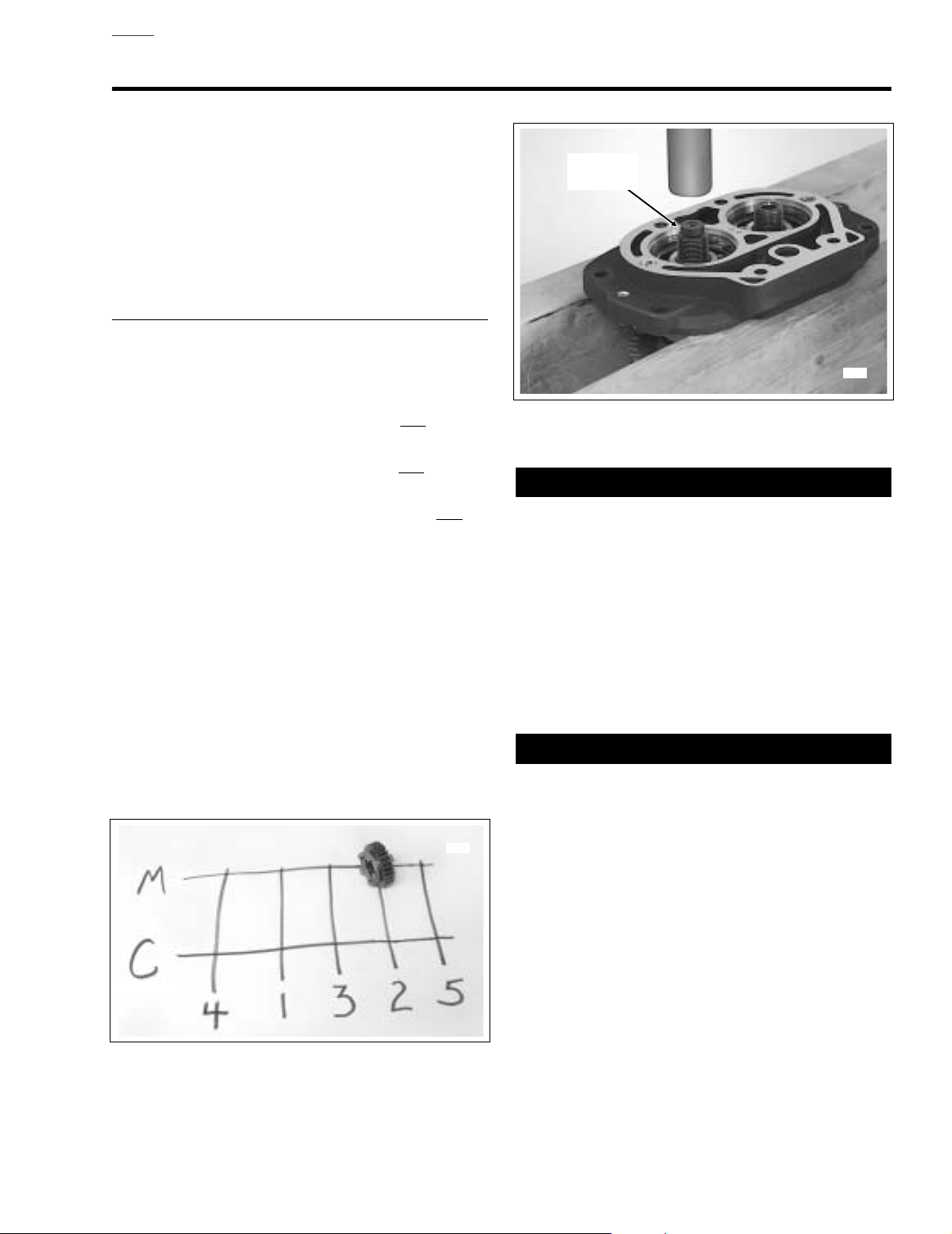
Figure D-2. Press Out Countershaft
Perform steps 1-6, 12, and 17-18 if replacing only
●
side door bearings.
1. Position the side door assembly on a bench with the
shafts pointing straight up, the mainshaft on the left hand
side. The mainshaft is the longer of the two shafts. See
Figure D-3.
2. Slide off the mainshaft 2nd gear (spur).
NOTE
To facilitate reassembly, label each gear as it is removed.
See Figure D-1.
3. Obtain the TRANSMISSION SHAFT RETAINING RING
PLIERS, Part No. J-5586.
the
9412
Always wear proper eye protection when removing retaining rings. Use the correct retaining ring pliers. Verify
that the tips of the pliers are not damaged or excessively
worn. Slippage may propel the ring with enough force to
cause eye injury.
4. Locate retaining ring just above the mainshaft 3rd gear
(spur). Move the retaining ring up approximately 3/8 inch
(9.5 mm) towards the free end of the shaft. Turn side
door assembly upside down and verify that mainshaft
3rd gear is still partially engaged with countershaft 3rd
gear.
Failure to move the retaining ring on the mainshaft can
cause countershaft 1st gear to contact mainshaft 3rd
gear when the countershaft is pressed out. On the other
hand, if the retaining ring is moved too far, loss of
engagement between mainshaft 3rd gear and countershaft 3rd gear can result in hard contact between these
two gears. Any hard contact can result in gear tooth
damage.
5. With the outboard side up, rest side door on parallel
blocks under ram of arbor press. Be sure that assembly
is flat and does not rest on dowel on inboard side.
Figure D-1. Note Gear Location During Disassembly
6. Center countershaft under ram. Install mainshaft plug
into hole at end of countershaft. Slowly apply pressure
until countershaft is free. See Figure D-2. Remove main-
shaft plug.
Appendix D D-1
Page 2
HOME
9413
1 10
11
3
2
4
126
4
3
6
5
4
13
3
4
3
7
146
3
4
4
3
68
9
15
16
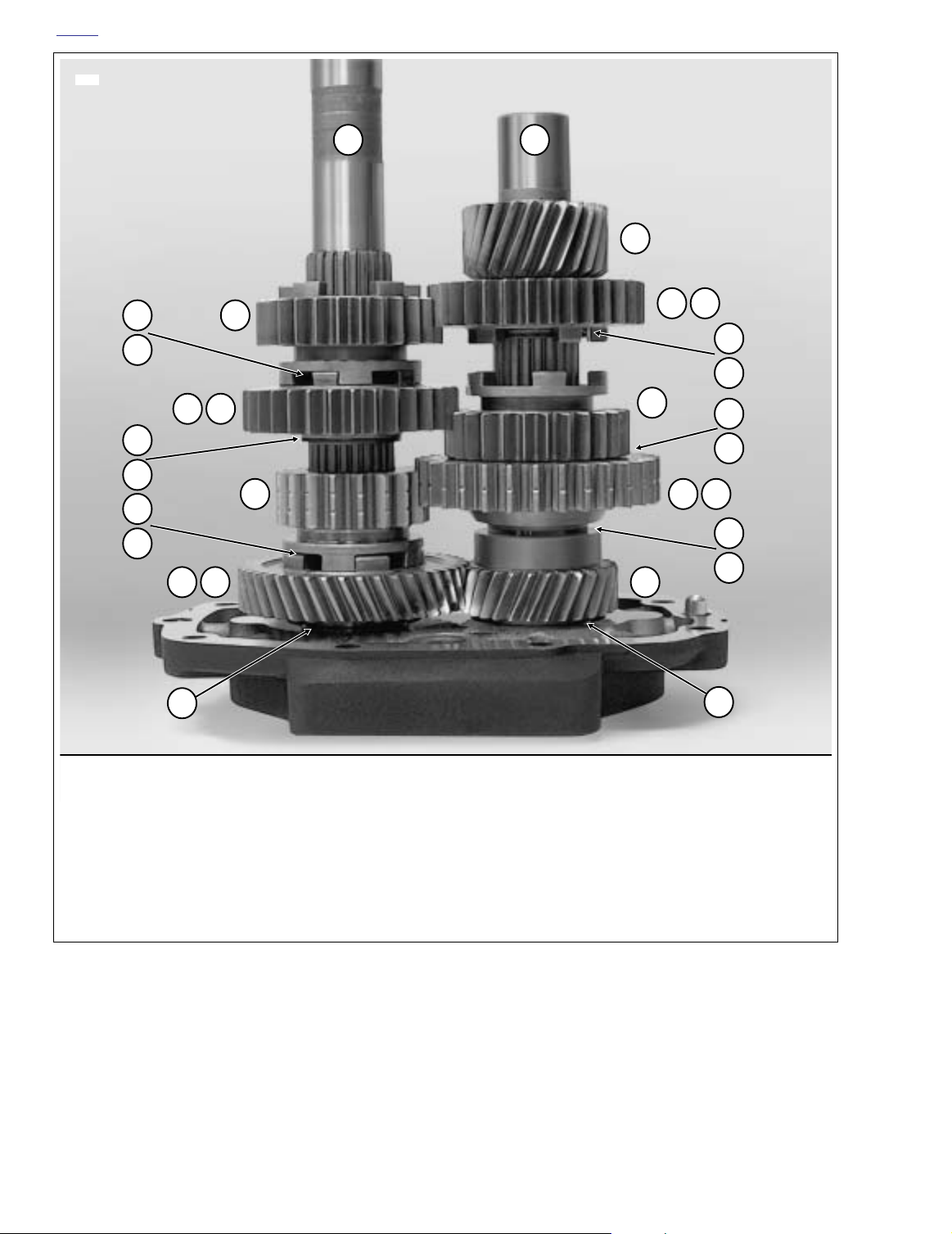
1. Mainshaft
2. 2nd Gear
3. Retaining Ring
4. Thrust Washer
5. 3rd Gear
6. Split Cage Bearing
7. 1st Gear
8. 4th Gear
7. Slide blue spacer and countershaft 4th gear (helical) off
threaded end of countershaft.
D-2 Appendix D
9. Gold Spacer
10. Countershaft
11. 5th Gear
12. 2nd Gear
13. 3rd Gear
14. 1st Gear
15. 4th Gear
16. Blue Spacer
Figure D-3. Fully Assembled Side Door
8. Secure countershaft in a vise with the threaded end top-
side. Be sure to install a pair of aluminum or brass jaw
inserts in vise to avoid parts damage. See Figure D-4.
Page 3

HOME
9415
Mainshaft
1st Gear
9416
17. Set the side door on a bench with the outboard side up.
Remove retaining ring from the bearing bore.
Countershaft
1st Gear
Aluminum
Jaws
Figure D-4. Disassemble/Assemble Countershaft
9. Remove retaining ring just above the countershaft 1st
gear (spur with single row of indents on teeth). Remove
thrust washer and countershaft 1st gear. Gently pull
apart the split cage bearing and remove. Remove second thrust washer.
NOTE
Depending upon whether one or both shafts were removed,
replace one or both side door bearings. Always replace the
bearing if the shaft was pressed out.
18. Turn side door over so that the inboard side is up and
place on flat plate under ram of arbor press. Apply pressure to outer race to press bearing from bore.
CLEANING AND INSPECTION
1. Clean all parts in cleaning solvent and blow dry with
compressed air.
2. Check gear teeth for damage. Replace the gears if they
are pitted, scored, rounded, cracked or chipped.
3. Inspect the engaging dogs on the gears. Replace the
gears if the dogs are rounded, battered or chipped.
4. Inspect the side door bearings. Bearings must rotate
freely without drag. Replace the bearings if pitted,
grooved, or if the shafts were removed.
10. Remove retaining ring above the countershaft 3rd gear
(spur). Remove countershaft 3rd gear.
11. Remove retaining ring just above the countershaft 2nd
gear (spur). Remove thrust washer and countershaft
2nd gear. Gently pull apart the split cage bearing and
remove.
12. Center mainshaft under ram of arbor press. Install mainshaft plug into hole at end of mainshaft. Slowly apply
pressure until mainshaft is free. Remove mainshaft plug.
13. Slide gold spacer, mainshaft 4th gear (helical), split cage
bearing and thrust washer off end of mainshaft.
14. Secure the mainshaft in a vise with the longer splined
end at the top. Be sure to install a pair of aluminum or
brass jaw inserts in vise to avoid parts damage. See Fig-
ure D-5.
15. Remove retaining ring above the mainshaft 1st gear
(spur with double row of indents on teeth). Remove
mainshaft 1st gear.
16. Remove retaining ring just above the mainshaft 3rd gear
(spur). Remove the thrust washer and mainshaft 3rd
gear. Gently pull apart the split cage bearing and
remove. Remove the second thrust washer. Remove the
last retaining ring, which was moved out of the groove
before the countershaft was pressed out.
Figure D-5. Disassemble/Assemble Mainshaft
Appendix D D-3
Page 4

HOME
ASSEMBLY
NOTES
Perform all steps if the transmission assembly was com-
●
pletely overhauled.
Perform steps 1-5 and 12-24 if only
●
one or more countershaft gears were replaced.
●
Perform steps 1-11 and 20-24 if only the mainshaft or
one or more mainshaft gears were replaced.
●
Perform steps 1-4, 11, and 18-24 if only the side door
bearings were replaced.
1. With the outboard side up, place side door on flat plate
under ram of arbor press.
NOTE
Note the two drill points between the bearing bores on the
side door. See Figure D-7. Two drill points indicate that the
side door must be fitted with the new style 12mm wide bearings. Installation of the old style 14mm wide bearings would
cover the retaining ring grooves.
2. Position
topside.
3. Applying pressure to outer race, press bearing into bore
until firm contact is made with the counterbore.
new
bearing over bore with the number stamp
the countershaft or
1WARNING1WARNING
Always wear proper eye protection when installing retaining rings. Use the correct retaining ring pliers. Verify
that the tips of the pliers are not damaged or excessively
worn. Slippage may propel the ring with enough force to
cause eye injury.
4. With the flat side in towards the bearing (beveled side
out), install
Depending upon the level of disassembly, replace one or
both side door bearings. Always replace the bearing if the
shaft was pressed out.
5. Obtain the TRANSMISSION SHAFT RETAINING RING
PLIERS, Part No. J-5586.
new
retaining ring in bearing bore.
NOTE
1WARNING1WARNING
Always use new retaining rings when assembling the
mainshaft and countershaft. Reusing retaining rings can
cause the transmission to become “locked” during
motorcycle operation, a situation which could result in
death or serious injury.
9417
Figure D-6. Press In Countershaft
6. Secure the mainshaft in a vise with the longer splined
end at the top. Be sure to install a pair of aluminum or
brass jaw inserts in vise to avoid parts damage.
7. Install
8. Slide thrust washer down mainshaft until it contacts
9. With the fork groove up, slide mainshaft 1st gear (spur
Verify that the mainshaft 1st gear has the doub
indents on teeth. Using a gear with a single row of
indents will result in transmission damage.
10. Slide thrust washer down the mainshaft until it contacts
11. With the inboard side up, place side door on flat plate
new
retaining ring approximately 3/8 inch (9.5
mm) below the bottom retaining ring groove.
retaining ring. Lightly coat split cage bearing with oil and
install in race just above thrust washer. Install mainshaft
3rd gear (spur) with the shifter dogs down. Install second
thrust washer. Install
above the bearing race.
with double row of indents on teeth) down mainshaft until
it contacts retaining ring. Install
groove above the gear. See Figure D-5.
the retaining ring. Lightly coat the split cage bearing
(double roller) with oil and install in race above the thrust
washer. Install mainshaft 4th gear (helical) over the
bearing with the shifter dogs down. Install gold spacer.
under ram of arbor press. Holding mainshaft assembly
together, remove from vise and position over bearing
bore in side door. Install mainshaft plug into hole at end
of mainshaft. Supporting inner race of bearing, press
mainshaft into bearing bore. Remove mainshaft plug.
new
retaining ring in groove just
CAUTION
Mainshaft
Plug
new
retaining ring in
le row of
D-4 Appendix D
Page 5

HOME
Mainshaft
Locknut
Countershaft
Locknut
Two Drill
Points
9414
Figure D-7. Install Mainshaft/Countershaft Locknuts
12. Secure the countershaft in a vise with the threaded end
topside. Be sure to install a pair of aluminum or brass
jaw inserts in vise to avoid parts damage.
21. Return side door assembly to bench. Position with the
shafts pointing straight up, the mainshaft on the left hand
side.
22. Move partially installed retaining ring into groove just
above the mainshaft 3rd gear.
23. Install mainshaft 2nd gear (spur) with the fork groove
down.
The final assembly appears as shown in Figure D-3.
24. Install spacer and locknut on the threaded end of each
shaft and tighten the nuts until finger tight. See Figure D-
7.
NOTE
For final tightening of the locknuts and installation of the side
door, see Section 7.6 MAINSHAFT/COUNTERSHAFT,
INSTALLATION.
13. Lightly coat split cage bearing with oil and install in race
next to the countershaft 5th gear.
14. Install countershaft 2nd gear (spur) over the bearing with
the shifter dogs up. Install thrust washer and
new
retain-
ing ring.
15. Install countershaft 3rd gear (spur) with the fork groove
down. Install
new
retaining ring in groove above the
gear.
16. Slide the thrust washer down the countershaft until it
contacts the retaining ring. Lightly coat the split cage
bearing with oil and install in the race just above the
thrust washer. Install countershaft 1st gear (spur with
single row of indents on teeth) with the taper up. Install
second thrust washer and
new
retaining ring. See Fig-
ure D-4.
17. Install countershaft 4th gear (helical) with the sleeve
down. Install blue spacer with the taper up.
18. With the inboard side up, place side door on flat plate
under ram of arbor press. Support inner race of bearing.
19. Holding countershaft assembly together, remove from
vise. Raising mainshaft 3rd gear until it contacts partially
installed retaining ring, position countershaft over bearing bore. Verify that taper on blue spacer is facing
towards the bearing.
20. Place mainshaft plug at end of countershaft. Be sure
that mainshaft and countershaft gears mesh and that
assembly is square. Press countershaft into bearing
bore. Remove mainshaft plug. See Figure D-6.
Appendix D D-5
Page 6

HOME
NOTES
D-6 Appendix D
 Loading...