

Page 1
2
HOME
SPECIFICATIONS 2.1
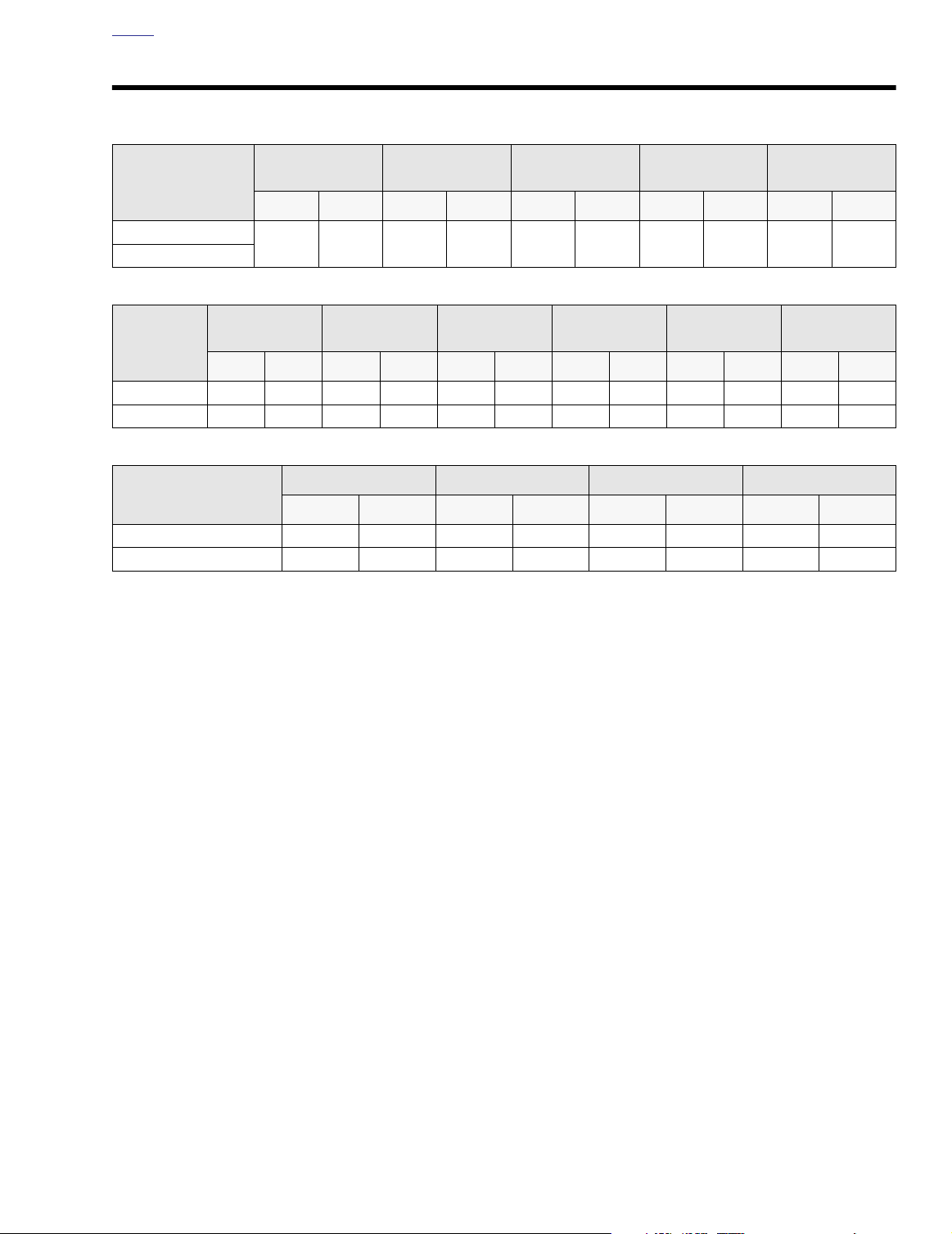
FUEL TANK
MODEL
FLHTP
FLHP
WHEEL BASE
MODEL
in. mm in. mm in. mm in. mm in. mm in. mm
FLHTP 63.5 1612.9 93.70 2379.9 39.0 990.6 5.1 129.5 61.0 1549.4 27.3 693.4
FLHP 63.5 1612.9 93.70 2379.9 34.5 876.3 5.1 129.5 55.1 1399.5 27.3 693.4
MODEL
FLHTP 758.0 343.8 1200 544.3 500 226.8 770 349.3
FLHP 723.0 327.9 1200 544.3 500 226.8 770 349.3
Gross vehicle weight rating (GVWR) (maximum allowable
loaded vehicle weight) and corresponding gross axle weight
rating (GAWR) are printed on a label fixed to the bottom of
the right front frame downtube.
TOTAL
gal. liter gal. liter qt. liter oz. liter oz. liter
5.0 18.92 - - 4.0 3.79 24 0.71 32 0.95
OVERALL
LENGTH
DRY WEIGHT GVWR GAWR FRONT GAWR REAR
lb. kg lb. kg lb. kg lb. kg
NOTE
FUEL TANK
RESERVE
OVERALL
WIDTH
OIL TANK
W/FILTER
ROAD
CLEARANCE
See Section 2.3 TIRES for important information regarding
tire data and tire inflation.
TRANSMISSION
(APPROX.)
OVERALL
HEIGHT
NOTE
PRIMARY
CHAINCASE
SADDLE
HEIGHT (Laden)
2004 FLT Police: Chassis 2-1
Page 2
HOME
VEHICLE IDENTIFICATION NUMBER 2.2
GENERAL
A 17-digit serial number, or Vehicle Identification Number
(VIN), is stamped on the right side of the frame backbone at
the rear of the steering head (and under the main harness
conduit). A label bearing the VIN code is also affixed to the
left side of the steering head. An abbreviated VIN is stamped
Market Designation
1 = Domestic
5 = International (HDI)
Manufacturer and Make
Harley-Davidson
Motorcycle Type
1 - Heavyweight
Vin Check Digit
Varies; can be 0 thru 9, or X.
between the front and rear cylinders on the left side of the
crankcase.
NOTE
Always give the complete VIN when ordering parts or making
an inquiry about your motorcycle.
Model Designation
FH - FLHPI
FM - FLHTPI
FT - FLHPEI
Model Year
4 - 2004
Engine Type
V - Carbureted
W - Fuel Injected
Introduction Date/Special Models
1 = Regular introduction date
2 = Mid-year introduction date
3 = California model
4 = Anniversary model
Assembly Plant
Y - York, PA
K - Kansas City, MO
Serial Number
1HD 1 FM W 13 4 Y 110000
Sample VIN as it appears on the steering head - 1HD1FMW134Y110000
Sample abbreviated VIN as it appears on the engine - FMW4110000
Figure 2-1. Vehicle Identification Number (VIN)
2-2 2004 FLT Police: Chassis
Page 3

HOME
11WARNING1WARNING
TIRES 2.3
GENERAL
The rear tire on FL police motorcycles is fit for solo riding
only. If converted to a two-up bike, that is, configured for passenger use (with luggage), then the rear tire needs to be
changed to one with a higher weight rating. Since it has long
been Harley-Davidson policy not to mix different types of tires
on the same vehicle, we strongly recommend that both front
and rear tires be replaced. In order to alert the customer to
this safety issue, the following warning appears on a label fitted to the rear fender approximately 1/4 inch (6.4 mm) behind
the domestic seat mounting hole.
11WARNING1WARNING
This vehicle has tires with weight ratings for one person
operation. If this vehicle is modified to carry two people,
the tires must be changed. See your local Harley-Davidson dealer for the proper replacement tires. Failure to follow this warning could cause tire failure which could
result in death or serious injury. (00096a)
Table 2-1. Tire Data
MODEL
TIRE
LOCATION
SIZE
NOTE
Use the tires recommended for civilian/pleasure vehicles of
the same year and model family.
The Dunlop front and rear tires on Harley-Davidson
motorcycles are not interchangeable. DO NOT put a front
tire at the rear of the vehicle or a rear tire at the front.
Improper placement of tires can adversely affect motorcycle stability and handling, which may lead to loss of
vehicle control resulting in death or serious injury.
(00026a)
Tire size, manufacturer’s description and inflation pressure
are listed below.
MANUFACTURER’S
DESIGNATION
TIRE
PRESSURE
(Cold)
FLHTP/FLHP
Front MT90B1672H
Rear MT90B1671H
Dunlop
D402F PT
Dunlop
D402 PT
36 psi
(248 kPa)
36 psi
(248 kPa)
2004 FLT Police: Chassis 2-3
Page 4
HOME
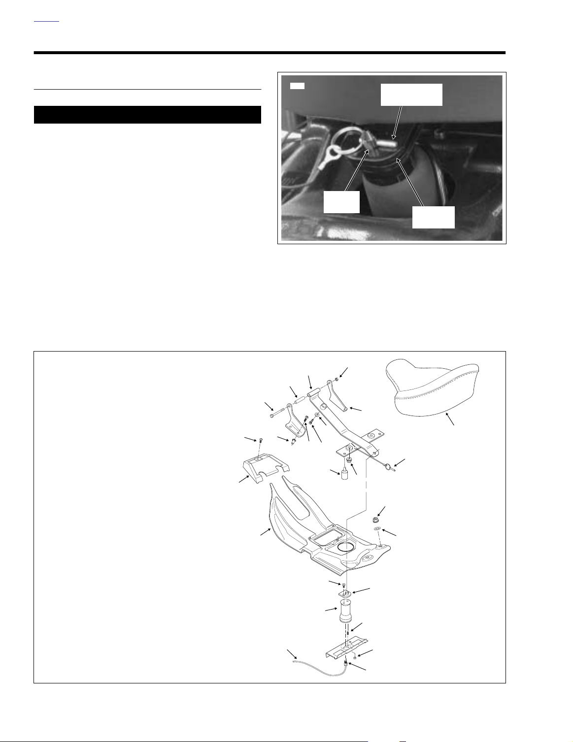
SEAT 2.4
OPERATION
CAUTION
Maximum seat air pressure is 100 psi (689 kPa). Normal
air pressure is between 30-45 psi (207-310 kPa). Minimum
air pressure is determined by rider weight. Do not operate with pressure so low that system bottoms out on
bumpy roads. (00167a)
NOTE
To set minimum air pressure, have rider sit on seat and
bounce to simulate riding conditions. Visually check for any
contact between air spring and frame components. Add air as
necessary.
1. Standing on left side of vehicle, press down on rear of
seat and pull quick release pin from hole in support post.
See Figure 2-2. Raise seat toward fuel tank console.
2. To lock seat in place, move seat down until support post
engages hole in rear seat bracket.
5872
Support
Post
Figure 2-2. Seat Latch
3. While pressing down on rear of seat, insert quick release
pin into hole of support post.
The seat does not adjust forward or backward.
Quick Release
Pin
Rear Seat
Bracket
NOTE
1. Air spring hose
2. Air spring
3. Screw (2) @ 36-60 in-lbs (4.1-6.8 Nm)
4. Trim panel
5. Seat faring
6. Screw
7. Rivnut (4)
8. Screw
9. Bushing
10. Seat support bracket
11. Nut @ 48-84 in-lbs (5.4-9.5 Nm)
12. Seat
13. Seat mount bracket (2)
14. Washer
15. Screw @ 60-120 in-lbs (6.8-13.6 Nm)
16. Screw (4) @ 15-20 ft-lbs (20.3-27.1 Nm)
17. Rubber bumper
18. Flange locknut (2) @ 96-144 in-lbs (10.9-16.3 Nm)
19. Quick release pin
20. Flange nut (2) @ 60-120 in-lbs (6.8-13.6 Nm)
21. Washer (2)
22. Rear seat bracket
23. Set screw (2)
24. Nut (2) @ 50-70 in-lbs (5.7-7.9 Nm)
25. Quick release fitting
6
5
10
11
9
8
13
16
15
14
19
7
12
17
18
20
4
3
2
23
1
25
21
22
24
p0047c2x
2-4 2004 FLT Police: Chassis
Figure 2-3. Air Seat Support
Page 5

HOME
Air
Reservoir
Air Valve
f1842x2x
Air Pressure
Gauge
AIR SEAT RESERVOIR
Removal
1. Remove luggage rack. See Section 2.6 LUGGAGE
RACK, REMOVAL, steps 1-5.
2. Alternately loosen screws on each side of motorcycle to
release ends of luggage rack from frame tube weldments. Continue loosening screws until luggage rack can
be raised high enough to remove air reservoir.
3. Remove two Phillips screws (with lockwashers) from luggage rack to release top of air reservoir bracket.
4. Remove two Phillips screws from license plate bracket to
free rear of air reservoir bracket. Be sure to hold reservoir as the last screw is removed or damage to fender
paint may occur when assembly is released.
5. Raise luggage rack and remove air reservoir from motorcycle.
6. Remove tee fittings from reservoir, if necessary.
Installation
1. Install tee fittings to air reservoir, if removed.
2. Position air reservoir beneath luggage rack exercising
caution to avoid scratching fender paint.
Figure 2-4. Air Seat Reservoir Air Valve
3. Slide Phillips screws through two holes in license plate
bracket and two holes in luggage rack engaging weld
nuts in air reservoir bracket. Alternately tighten screws
until snug.
4. Alternately tighten screws on each side of motorcycle to
secure ends of luggage rack to frame tube weldments.
5. Install luggage rack. See Section 2.6 LUGGAGE RACK,
INSTALLATION, steps 1-4 and 6-13.
1. Air seat reservoir and
bracket
2. Lockwasher (2)
3. Screw (2)
4. Air pressure gauge
5. Air tube
6. Compression fitting
7. Air valve
8. Protective cap
9. Tee fitting (2)
10. Screw (2)
6
8
3
5
7
2
4
9
1
Figure 2-5. Air Seat Reservoir
10
p0048b2x
2004 FLT Police: Chassis 2-5
Page 6

HOME
FOOTBOARDS 2.5
GENERAL
FLHTP and FLHP models are equipped with adjustable footboards.
ADJUSTMENT
Right Side
1. Loosen two allen head socket screws (with lockwashers
and flat washers) to release right side footboard brackets
from frame weldment. For best results, approach from
left side of vehicle using a 3/8 inch ball allen with extension.
2. Move the footboard to one of two positions. Alternately
tighten allen head socket screws to 30-35 ft-lbs (40.7-
47.5 Nm).
11WARNING1WARNING
Rear brake will not operate properly if brake pedal cannot be fully depressed. After adjusting right footboard,
check for minimum clearance of 2.25 inches (57 mm)
between bottom of brake pedal and top of footboard.
Failure to allow for proper clearance can lead to loss of
braking performance, which could result in death or serious injury.
4. At footboard rear bracket, slide upper hex bolt through
frame weldment, jiffy stand bracket and footboard
bracket thru hole. Install lockwasher and locknut. Slide
lower hex bolt (with lockwasher) through frame weldment
and jiffy stand bracket into threaded hole of footboard
bracket. Alternately tighten two hex bolts to 15-20 ft-lbs
(20.3-27.1 Nm).
NOTE
Perform a visual check to verify that both footboards are at
the same height.
Left Side
1. Loosen the allen head socket screw (with lockwasher
and flat washer) to release the footboard forward bracket
from frame weldment. For best results, approach from
opposite side of vehicle using a 3/8 inch ball allen.
2. To free footboard rear bracket from frame weldment and
jiffy stand bracket, remove lower hex bolt (with lockwasher) and upper hex bolt (with lockwasher and locknut).
3. Move the footboard to one of two positions. Alternately
tighten allen head socket screw to 30-35 ft-lbs (40.7-47.5
Nm).
2-6 2004 FLT Police: Chassis
Page 7

HOME
6046
LUGGAGE RACK 2.6
REMOVAL
1. Remove both saddlebags.
2. On the right side of the motorcycle, locate the air seat
reservoir air valve under the luggage rack, and on the left
side, the rear shock air valve just below the chrome
frame cover. See Figure 2-6.
11WARNING1WARNING
Exercise caution when bleeding air from the air valves.
Moisture combined with lubricant (either from shock
assembly or drip oiler in the air compressor lines) may
be ejected onto the rear wheel, tire and/or brake components and adversely affect traction and/or braking efficiency, which could result in death or serious injury.
f1842x2x
f2018x2x
Air Seat
Reservoir
Air Valve
Rear Shock
Air Valve
Figure 2-7. Remove Luggage Rack
3. Remove protective cap from each air valve and depress
pin to bleed air from both reservoir and shocks. To purge
rear air suspension lines of any oil, add 3-5 psi (20.7-
34.5 kPa) before releasing air. Depress collar on each
compression fitting and pull out air tube.
4. Remove bolt (with flat washer) to remove saddlebag front
mounting bracket from chrome frame cover. Remove
Phillips screw and then remove frame cover. Repeat step
on opposite side of motorcycle.
5. Remove two bolts to free license plate bracket from bottom support tube.
6. Remove screws (with spacers) on each side of motorcycle to release ends of luggage rack from frame tube
weldments.
7. Remove pole lamp. See Section 8.5 POLE LAMP.
8. Slide luggage rack toward rear of motorcycle to clear
front bushings, and then rotate rack upward to clear
frame tubes. See Figure 2-7.
INSTALLATION
Figure 2-6. Air Valves
1. Place luggage rack into position inboard of frame tubes.
2004 FLT Police: Chassis 2-7
Page 8

HOME
2. Install screws (with spacers) on each side of motorcycle
to secure ends of luggage rack to frame tube weldments.
3. Install two bolts to fasten license plate bracket to bottom
support tube.
4. Position chrome frame cover on frame tube and install
Phillips screw. Install bolt (with flat washer) to install saddlebag front mounting bracket, but do not tighten. Repeat
step on opposite side of motorcycle.
5. Install pole lamp. See Section 8.5 POLE LAMP.
6. Depress collar on compression fitting of air seat reservoir, and insert air tube until it bottoms. Gently tug on
tube to verify that it is locked in place.
CAUTION
Maximum seat air pressure is 100 psi (689 kPa). Normal
air pressure is between 30-45 psi (207-310 kPa). Minimum
air pressure is determined by rider weight. Do not operate with pressure so low that system bottoms out on
bumpy roads. (00167a)
7. Fill air reservoir to desired pressure. Install protective
cap on air valve. See upper frame of Figure 2-6.
Table 2-2. Rear Air Suspension Pressures
Shock Loading
Solo rider up to 150 lbs. (68 kg) 0 0
Solo rider 150-200 lbs. (68-91 kg) 0-10 0-69
Solo rider 200-250 lbs. (91-113 kg) 5-15 35-103
Maximum GVWR (see Section 2.1
SPECIFICATIONS)
Recommended
Pressures
PSI
0-35
20-35 138-241
kPa
0-241
11WARNING1WARNING
Use this table as a starting point in determining suitable rear air suspension pressures. Do not exceed
maximum GVWR when loading vehicle and do not
pressurize system in excess of 35 psi (241 kPa).
Excessive load weight and/or air suspension pressure can adversely affect handling and lead to loss
of vehicle control, which could result in death or serious injury.
NOTE
To set minimum air pressure, have rider sit on seat and
bounce to simulate riding conditions. Visually check for any
contact between air spring and frame components. Add air as
necessary.
8. Observe air pressure gauge. If leakage occurs, then
remove tube and inspect end for burrs or damage. If
either condition is found, snip off end of tube and insert
back into fitting.
9. Depress collar on compression fitting of each shock and
insert air tube until it bottoms. Gently tug on tube to verify
that it is locked in place.
10. Fill shocks to desired pressure. See Ta ble 2-2.
CAUTION
All air components fill rapidly. Use a small hand or foot
operated air pump to avoid possible damage to shocks
or air suspension components.
NOTE
An AIR SUSPENSION PUMP AND GAUGE (Part No. HD-
34633) is available at your Harley-Davidson dealer.
11. Observe air pressure gauge while filling. If leakage
occurs, remove tubes and inspect ends for burrs or damage. If either condition is found, snip off end of tube and
insert back into fitting.
12. When air pressure remains constant, install protective
cap on air valve.
13. Install saddlebags. Using an open end/box wrench,
tighten saddlebag front mounting bracket bolts.
2-8 2004 FLT Police: Chassis
Page 9

HOME
1. Headlamp Nacelle
2. Nut
3. Flat Washer
4. Flange Nut
5. Chrome Strip
6. Phillips Screw (2)
7. Tachometer Bracket
8. Acorn Nut (2)
9. Fork Lock Plate
10. Handlebar Clamp Shroud
11. Stud Plate
f1458d2x
7
8
9
6
10
11
5
4
3
2
1
INSTRUMENT MOUNTING BRACKET: FLHP 2.7
GENERAL
The Instrument Mounting Bracket relocates the tachometer to
allow for the addition of a radio and speaker.
NOTE
The two rear holes in the handlebar clamp shroud allow the
rider to adjust the handlebars without having to remove the
shroud. To keep out moisture and debris, be sure to install
plastic plugs back into holes after handlebar adjustment.
INSTALLATION
1. Remove windshield. See Section 2.31 WINDSHIELD/
HEADLAMP NACELLE (FLHR/C/S), REMOVAL, in the
2004 Touring Models Service Manual (Part No. 99483-
04).
2. Remove Phillips screw at the bottom of the headlamp
door (chrome ring). Remove the headlamp door.
3. Remove the eight Phillips screws to free the headlamp
housing from the headlamp nacelle.
4. Squeeze the two external tabs (if present) to remove the
wire connector at the back of the headlamp bulb.
Remove headlamp housing assembly from the vehicle.
5. Reaching inside the headlamp nacelle, remove flange
nut to release the chrome strip at the top of the nacelle.
See Figure 2-8.
6. Carefully pry off the fork lock plate at the rear of the handlebar clamp shroud. Remove two Phillips screws
beneath the lock plate.
7. Loosen the Phillips screw from tab at the front of the handlebar clamp shroud (but do not remove).
8. Remove two acorn nuts from the left side fork studs.
Remove acorn nuts from the right side fork studs.
9. Cover front fender with suitable material to protect fender
paint. Remove the passing lamp bracket from the left and
right side fork studs and carefully set on front fender.
10. Remove grommets (and clutch cable clamp) from the left
and right side fork studs.
11. Reaching inside the headlamp nacelle, disconnect
tachometer connector [108], 3-place Deutsch.
12. Remove the handlebar clamp shroud from the vehicle,
while gently pulling the tachometer conduit and connector out of the headlamp nacelle. See Figure 2-9.
Figure 2-8. Headlamp Nacelle Assembly
13. Remove two acorn nuts and flat washers to release
tachometer bracket from the handlebar clamp shroud.
14. A peel and stick foam tape on the stud plate holds it in
place on the inboard side of the handlebar clamp shroud,
Place the instrument mounting bracket over the studs
and secure using hardware provided by manufacturer.
See upper frame of Figure 2-11.
2004 FLT Police: Chassis 2-9
Page 10

HOME
f1458e2x
Figure 2-9. Handlebar Clamp Shroud
1
2
5531
Install instrument mounting bracket on stud plate.
p0044x5x
5532
3
6
5
4
1. Acorn Nut
2. Instrument Mounting
Bracket
3. Handlebar Clamp Shroud
Figure 2-10. Instrument Mounting Bracket Assembly
15. Secure slotted tab of instrument mounting bracket to
front of handlebar clamp shroud using nut and bolt provided by manufacturer. See middle frame of Figure 2-11.
16. Place tachometer bracket over studs on instrument
mounting bracket and install two acorn nuts with flat
washers. See lower frame of Figure 2-11.
17. Part the halves of the headlamp nacelle slightly. With the
flat washer on the handlebar clamp shroud facing the
inside surface of the nacelle, slide the Phillips screw
down the gap until the shroud is in position at top of
nacelle. See Figure 2-9.
4. Stud Plate
5. Screw
6. Nut
Install instrument mounting bracket front bolt.
5530
Install tachometer bracket.
Figure 2-11. Install Instrument Mounting Bracket
18. Raising handlebar clamp shroud slightly, feed tachometer connector and conduit into the headlamp nacelle.
Install shroud over mating flange while routing tachometer conduit through opening for left side handlebar.
Reaching inside headlamp nacelle, mate pin and socket
halves of tachometer connector.
2-10 2004 FLT Police: Chassis
Page 11

HOME
19. With the halves of the nacelle mated, tighten the Phillips
screw in the tab of the handlebar clamp shroud to 10-20
in-lbs
(1.1-2.3 Nm). If necessary, temporarily install a
small cable strap into holes at the bottom of the nacelle
(headlamp housing flange) to hold the halves together.
20. Install two Phillips screws to fasten handlebar clamp
shroud to the fork lock mechanism. Install fork lock plate.
21. Inserting weld stud on chrome strip into hole at the top of
the headlamp nacelle, reach inside the nacelle to install
flange nut. Tighten flange nut to 15-20
in-lbs
(1.7-2.3
Nm).
22. Install grommets on the left and right side fork studs.
23. Slide passing lamp bracket onto the left and right side
fork studs. Verify that four grommets are positioned on
the inboard side of the passing lamp brackets.
24. Install acorn nuts on the fork studs and tighten to 72-108
in-lbs
(8.1-12.2 Nm). Be sure to capture the clutch cable
clamp on the upper left stud before installing the acorn
nut.
25. Install wire connector at the back of headlamp bulb.
26. Align holes in headlamp housing with those in headlamp
nacelle (headlamp door bracket at bottom). Install the
eight Phillips screws.
27. Fit the square-shaped portion of the headlamp door
spring into the slot at the top of the headlamp housing
and then snap the headlamp door (chrome ring) into
place. Install Phillips screw at the bottom of the headlamp door.
28. Install windshield. See Section 2.31 WINDSHIELD/
HEADLAMP NACELLE (FLHR/C/S), INSTALLATION, in
the 2004 Touring Models Service Manual (Part No.
99483-04).
2004 FLT Police: Chassis 2-11
Page 12

HOME
NOTES
2-12 2004 FLT Police: Chassis
 Loading...