

Page 1
HOME
SPECIFICATIONS 7.1
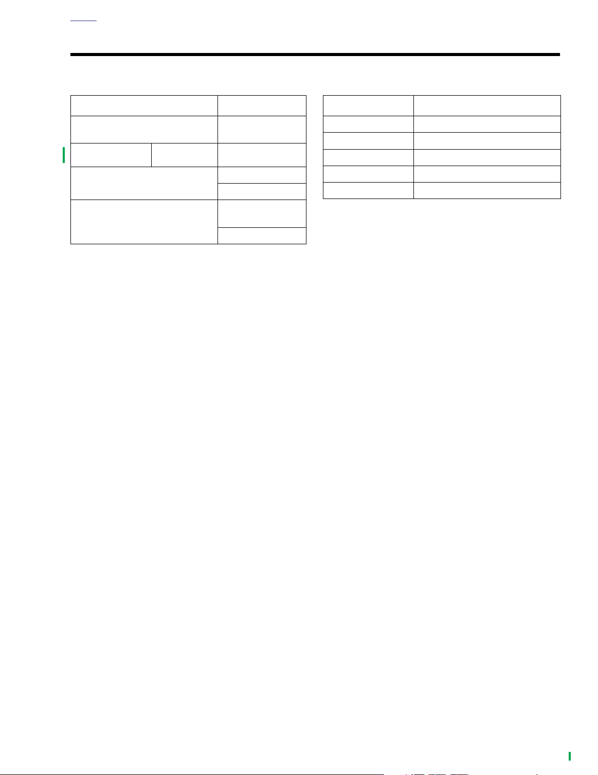
Table 7-1. Transmission Data
TRANSMISSION DATA
Ty p e
SYN3
Capacity (dry)
Capacity (wet)
Quart Part No.
5-speed forward -
constant mesh
99824-03/00QT
24 oz.
710 ml
Approximately
20-24 oz.
590-710 ml
Table 7-2. Internal Gear Ratios
GEAR INTERNAL GEAR RATIOS
First 3.21
Second 2.21
Third 1.57
Fourth 1.23
Fifth 1.00
2004 FLHTCSE: Transmission 7-1
Page 2
HOME
SERVICE WEAR LIMITS 7.2
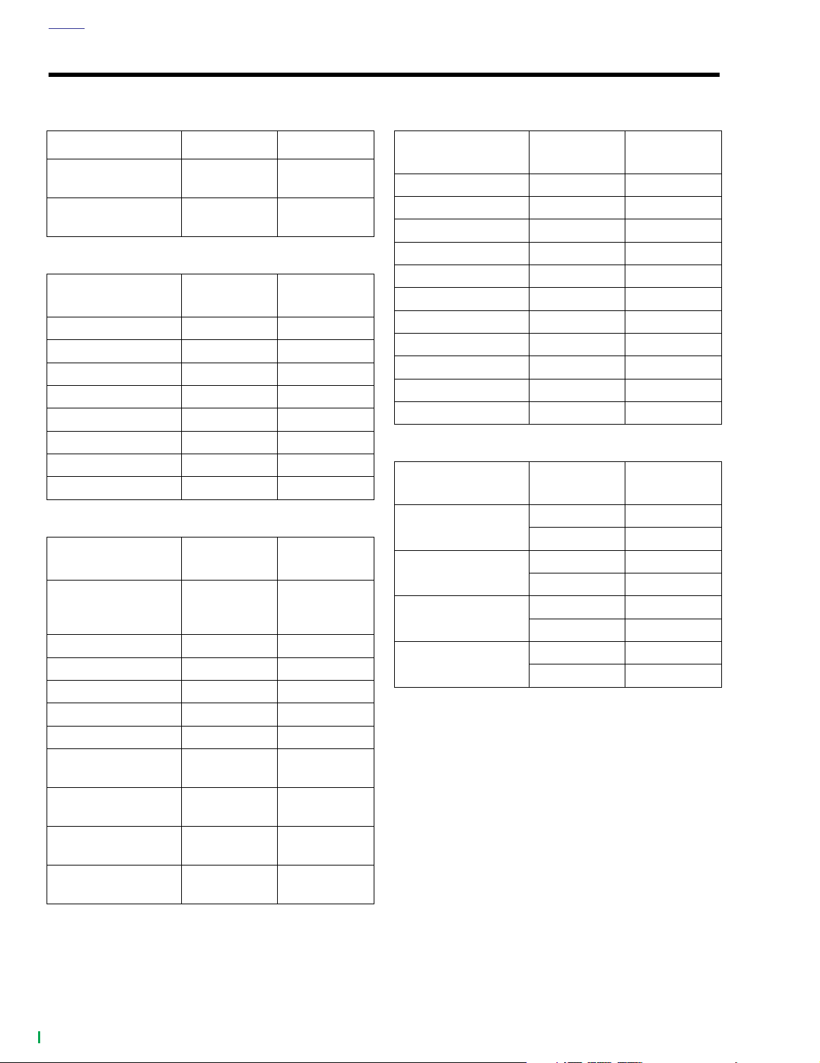
Table 7-3. Shifter Forks
SHIFTER FORKS IN. MM
Shifter fork to cam
groove end play
Shifter fork to gear
groove end play
0.0017-0.0019 0.043-0.048
0.0010-0.0110 0.025-0.279
Table 7-4. Mainshaft
MAINSHAFT
TOLERANCE
Mainshaft runout 0.000-0.003 0.000-0.08
Mainshaft end play none none
1st gear clearance 0.0000-0.0080 0.000-0.203
2nd gear clearance 0.0000-0.0800 0.000-2.032
3rd gear end play 0.0050-0.0420 0.127-1.067
3rd gear clearance 0.0003-0.0019 0.008-0.048
4th gear end play 0.0050-0.0310 0.127-0.787
4th gear clearance 0.0003-0.0019 0.008-0.048
IN. MM
Table 7-5. Main Drive Gear (5th)
MAIN DRIVE
GEAR (5TH)
Bearing fit in
transmission case
(loose)
Fit in bearing (tight) 0.0009 0.023
Fit in bearing (loose) 0.0001 0.0025
Fit on mainshaft 0.0001-0.0009 0.0025-0.023
End play none none
Fit in side door (tight) 0.0014-0.0001 0.036-0.0025
Fit on countershaft
(tight)
Fit on countershaft
(loose)
Fit on mainshaft
(tight)
Fit on mainshaft
(loose)
IN. MM
0.0003-0.0017 0.008-0.043
0.0008 0.020
0.00001 0.0003
0.0007 0.018
0.0001 0.0025
Table 7-6. Countershaft
COUNTERSHAFT
TOLERANCE
Countershaft runout 0.000-0.003 0.00-0.08
Countershaft end play none none
1st gear clearance 0.0003-0.0019 0.008-0.048
1st gear end play 0.0050-0.0039 0.127-0.099
2nd gear clearance 0.0003-0.0019 0.008-0.048
2nd gear end play 0.0050-0.0440 0.127-1.118
3rd gear clearance 0.0000-0.0080 0.000-0.203
4th gear clearance 0.0000-0.0080 0.000-0.203
4th gear end play 0.0050-0.0390 0.127-0.991
5th gear clearance 0.0000-0.0080 0.000-0.203
5th gear end play 0.0050-0.0040 0.127-0.102
IN. MM
Table 7-7. Shifter Dogs
SHIFTER DOG
GEARS
2nd-5th
2nd-3rd
1st-4th
1st-3rd
MINIMUM
CLEARANCE
0.035 in. 0.139 in.
0.89 mm 3.53 mm
0.035 in. 0.164 in.
0.89 mm 4.17 mm
0.035 in. 0.152 in.
0.89 mm 3.86 mm
0.035 in. 0.157 in.
0.89 mm 3.99 mm
MAXIMUM
CLEARANCE
7-2 2004 FLHTCSE: Transmission
Page 3

HOME
TORQUE VALUES 7.3
ITEM TORQUE NOTES
Bleeder valve 80-100
Clutch fluid line flare nut 80-115
Clutch fluid reservoir banjo bolt 17-22 ft-lbs 23-31 Nm page 7-5
Clutch fluid reservoir cover 6-8
Clutch release cover 120-144
Filler plug/dipstick 25-75
Negative battery cable 60-96
Tr ansmission drain plug 14-21 ft-lbs 19-28 Nm page 7-5
in-lbs
in-lbs
in-lbs
in-lbs
in-lbs
in-lbs
9-11 Nm page 7-5
9-13 Nm page 7-5
0.7-0.9 Nm page 7-5
14-16 Nm page 7-5
2.8-8.5 Nm page 7-5
6.8-10.9 Nm page 7-5
2004 FLHTCSE: Transmission 7-3
Page 4

HOME
CLUTCH RELEASE COVER 7.4
REMOVAL
1. Remove filler plug/dipstick.
2. Place a suitable container under transmission. Remove
magnetic drain plug at bottom right of oil pan and drain
transmission lubricant.
3. Remove seat. See 2.13 SEAT.
1WARNING1WARNING
To prevent accidental vehicle start-up, which could
cause death or serious injury, remove maxi-fuse before
proceeding. (00251a).
4. Remove negative battery cable (black) from negative (-)
battery terminal.
5. Remove the right side of the exhaust system. See
EXHAUST in the Touring Models Service Manual.
6. See Figure 7-1. Place a suitable container under clutch
release cover. Remove cap and open bleeder valve and
loosen flare nut and allow clutch fluid to drain.
7. Remove flare nut on outside of the clutch release cover.
Remove clutch fluid line and drain line.
IMPORTANT NOTE
Dispose of clutch fluid in accordance with local regulations.
9930
1
2
3
1. Bleeder valve (cap removed)
2. Flare nut
3. Clutch fluid line
Figure 7-1. Clutch Release Cover
(exhaust system removed)
9923
2
1
1
8. See Figure 7-3. Remove o-ring on end of clutch fluid
line. Discard o-ring.
NOTE
Clutch fluid line o-ring may stick to inside of clutch release
cover. Use a pick to remove old o-ring and other debris.
9. Remove clutch release cover fasteners, cover and gasket.
10. Clean and inspect clutch release cover. Clean with
denatured alcohol or D.O.T. 5 SILICONE BRAKE FLUID,
only.
NOTE
If required, replace locating dowels in transmission side door.
11. See Figure 7-2. Disassemble and inspect secondary
clutch actuator. Rebuild if required. See 7.5 SECOND-
ARY CLUTCH ACTUATOR.
1. Hole for locating dowel
2. Secondary clutch actuator
Figure 7-2. Inside Clutch Release Cover
7-4 2004 FLHTCSE: Transmission
Page 5

HOME
9994
INSTALLATION
1. Place a
and position clutch release cover on transmission side
door.
2. Install fasteners with the two short fasteners at the top of
the release cover. Tighten fasteners to 120-144
(14-16 Nm).
3. See Figure 7-3. Install a
the end of the clutch fluid line.
4. Install clutch fluid line flare nut to clutch release cover.
Tighten to 80-115
5. Loosen bleeder valve.
new
clutch release gasket on locating dowels
new
clutch fluid line o-ring on
in-lbs
(9-13 Nm).
in-lbs
1WARNING1WARNING
Be sure NO clutch fluid gets on rear tire, wheel or brakes
when adding clutch fluid. Traction will be adversely
affected which could result in loss of control of the
motorcycle and death or serious injury.
1WARNING1WARNING
Do NOT allow foreign matter to enter the clutch master
cylinder reservoir. Dirt or debris in the reservoir may
cause improper operation of the clutch and equipment
damage.
1WARNING1WARNING
Direct contact of D.O.T. 5 SILICONE BRAKE FLUID with
eyes may cause eye irritation, swelling, and redness.
Avoid eye contact. In case of eye contact flush with large
amounts of water and seek medical attention immediately. Swallowing large amounts of D.O.T. 5 SILICONE
BRAKE FLUID may cause digestive discomfort. If swallowed, seek medical attention immediately. Use in well
ventilated area. KEEP OUT OF REACH OF CHILDREN.
Figure 7-3. Clutch Fluid Line O-ring
8. Tighten fasteners as follows:
a. Reservoir banjo bolt to 17-22 ft-lbs (23-31 Nm).
b. Bleeder valve to 80-100
c. Reservoir cover screws to 6-8
9. Install bleeder valve cap.
10. Inspect o-ring on transmission lubricant drain plug and
replace as necessary. Install drain plug and tighten to
14-21 ft-lbs (19-28 Nm).
11. Fill the transmission with 20-24 oz. (590-710 ml) of
transmission lubricant or until the lubricant level on the
dipsitck of the filler plug is at the F (full) mark with the
motorcycle level and upright and the filler plug resting on
the threads. Use only Harley-Davidson TRANSMISSION
LUBRICANT, Part No. 98853-96 (case/quarts), or Part
No. 98852-96 (case/gallons).
12. Inspect the filler plug/dipstick o-ring and install filler plug/
dipstick. Tighten the plug to 25-75
13. Install exhaust system. See EXHAUST in Touring Models Service Manual.
in-lbs (
9-11 Nm).
in-lbs (
in-lbs
0.7-0.9 Nm).
(2.8-8.5 Nm).
1WARNING1WARNING
The piston in the secondary clutch actuator is under
pressure. Squeezing the clutch hand lever could force
the piston out of its housing with sufficient force to
cause death or serious injury.
6. Remove clutch fluid reservoir cover and fill with D.O.T. 5
SILICONE BRAKE FLUID. Allow fluid to fill clutch line
until a steady flow of clutch fluid flows from bleeder
valve. Tighten bleeder valve.
NOTE
When filling an empty clutch fluid line, a Snap-on BASIC
VACUUM BRAKE BLEEDER with a fitting that mates to the
bleeder valve threads can be used to initially draw the fluid
down the clutch line with little or no air in the line.
7. Bleed clutch fluid line. See BLEEDING CLUTCH FLUID
LINE.
14. Install negative battery cable. Tighten bolt to 60-96
lbs
(6.8-10.9 Nm).
15. Install seat. See 2.13 SEAT.
2004 FLHTCSE: Transmission 7-5
in-
Page 6

HOME
SECONDARY CLUTCH ACTUATOR 7.5
REBUILD
1. Remove the clutch release cover. See 7.4 CLUTCH
RELEASE COVER.
1WARNING1WARNING
Pressurized air can blow debris into your face and eyes.
Always wear eye protection or a face shield when using
pressurized air. Failure to take adequate safety precautions could result in death or serious injury.
2. Remove piston.
a. If the bleeder valve was removed, reinstall.
b. Support on a wooden block and apply low pressure
compressed air to clutch fluid line hole to remove
piston from cover bore.
3. See Figure 7-4. If necessary, wiggle piston from actuator
bore to completely remove.
4. Remove the spring. Discard spring and piston assembly.
CAUTION
8880
1
2
3
1. Piston
2. Primary cup
3. Spring
Figure 7-4. Secondary Clutch Actuator Components
Damaged pistons or piston bores will leak when reassembled. Do not use metal objects to remove or install
objects from piston bores. Prevent damage to bores by
only using a wooden toothpick when servicing secondary clutch actuator.
5. Lubricate
service kit lubricant.
6. Install
7. While pushing piston into actuator bore, use a wooden
tooth pick or the end of a cable wrap to prevent primary
cup from rolling over.
new
new
piston assembly and piston bore with the
spring.
7-6 2004 FLHTCSE: Transmission
 Loading...