

Page 1
H
Spare
ECM Power
f2223x9x
EFI System
Relay
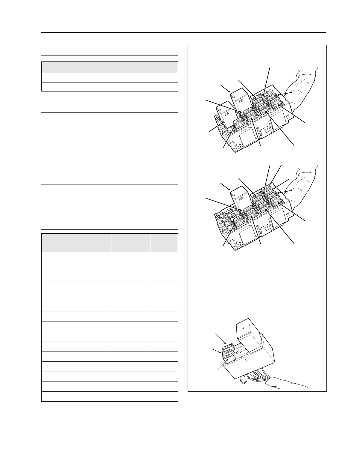
System Fuse Block (Under Left Side Cover)
EFI Fuse Block (Under Right Side Cover)
11
10
9
1
8
5
4
3
2
FLHR/C/S
11
10
9
1
8
7
6
5
4
3
2
FLTR, FLHT/C/U
1. Headlamp
2. Ignition
3. Lighting
4. Instruments
5. Brakes/Cruise
6. Radio Memory
7. Radio Power
8. Accessory
9. Battery
10. Brake Light Relay
11. P&A
12. Starter Relay
12
f2210x8x
f2204x8x
Fuel Pump
OME
SPECIFICATIONS 8.1
IGNITION TIMING
ALL FL Models
RANGE TDC - 50˚ BTDC
START
ALTERNATOR SYSTEM
TDC
Output Voltage @ 3600 rpm 14.3-14.7
38 Amp:
FLHR, FLHRI, FLHRCI, FLHRS, FLHRSI, FLHT, FLHTC
45 Amp:
FLHTI, FLHTCI, FLHTCUI, FLTRI
BATTERY
Voltage 12V
Amperes – 28 AH @ 20 Hour Rate
FUSES
System Fuses
Maxi-Fuse 40 Orange
Headlamp 15 Blue
Ignition 15 Blue
Lighting 15 Blue
Instruments 15 Blue
Brakes/Cruise 15 Blue
Radio Memory 15 Blue
Radio Power 10 Red
Accessory 15 Blue
Battery 15 Blue
P & A 15 Blue
EFI Fuses
Fuel Pump 15 Blue
ECM Power 15 Blue
Circuit
Rating
(Amperes)
Color
Figure 8-1. Fuse Locations
2004 Touring: Electrical 8-1
Page 2
H
OME
SPARK PLUG
Part No.
32317-86A 6R12 12 mm
Be sure spark plugs are gapped to specification before installation.
No. Size Gap
0.038-0.043 in.
0.97-1.09 mm
NOTE
TORQUE VALUES
Item
Ignition module socket
head screws
MAP sensor TORX screw 25-35
Ignition coil bracket
socket screws
Spark plug 12-18 ft-lbs 16-24 Nm
Stator to crankcase TORX
screws
Battery cable bolt 60-96
Voltage regulator locknuts 70-100
Battery hold-down clamp
TORX bolt
Headlamp door screw 9-18
Passing lamp bracket fork
bracket TORX bolts
Passing lamp bracket fork
bracket stud acorn nuts
Ta il lamp lense screws 20-24
Ta il lamp circuit board/
plastic bracket
Rear fender tip lamp nuts 20-25
Front fender tip lamp nuts 20-25
Front fender trim strip tee
bolt nuts
Ignition switch to upper
fork bracket
Fairing cap TORX screws 25-30
Ignition switch button
head screws
Ignition switch
nut
DOM 50-70
HDI 125-150
ft/in-lbs Nm
50-60
in-lbs
in-lbs
84-144
in-lbs
55-75
in-lbs
in-lbs
in-lbs
15-20 ft-lbs 20-27 Nm
in-lbs
15-20 ft-lbs 20-27 Nm
72-108
in-lbs
in-lbs
40-48
in-lbs
in-lbs
in-lbs
10-15
in-lbs
36-60
in-lbs
in-lbs
18-23
in-lbs
in-lbs
in-lbs
5.7-6.8 Nm
2.8-4.0 Nm
9.5-16.3 Nm
6.2-8.5 Nm
6.8-10.9 Nm
7.9-11.3 Nm
1.0-2.0 Nm
8.1-12.2 Nm
2.3-2.7 Nm
4.5-5.4 Nm
2.3-2.8 Nm
2.3 - 2.8 Nm
1.1-1.7 Nm
4.1-6.8 Nm
2.8-3.4 Nm
2.0-2.6 Nm
5.7-7.9 Nm
14.1-16.9 Nm
Continued ...
Item
Fork lock to upper fork
bracket (FLHR/C/S)
Ignition switch screws
(FLHR/C/S)
Instrument bezel TORX
screws
Handlebar clamp to
master cylinder housing
screws
Lower and upper handlebar switch housing TORX
screws
Handlebar clamp to
clutch lever bracket TORX
screws
Neutral switch 120-180
Horn stud flange nut
(10mm)
Horn bracket acorn nut to
rubber mount stud
2 inch diameter gauge
nuts
Tachometer bracket
socket screws
Speedometer speed
sensor screw
Speedometer bracket
socket screws
Console mounting bolt
acorn nut (FLHR/C/S)
Console pod Phillips
screws
Fuel tank canopy TORX
screws
Cruise module locknuts 60-96
Radio to support bracket
socket screws
Upper fairing speaker
lower TORX screw
Upper fairing speaker
upper TORX screws
Throttle cable J-clamp
screw to wellnut
(FLHR/C/S)
Ground post flange nuts 50-90
ft/in-lbs Nm
36-60
20-30
25-35
60-80
35-45
60-80
80-100
80-100
10-20
10-20
84-108
10-20
50-90
6-11
18-24
35-45
22-28
35-50
9-18
in-lbs
in-lbs
in-lbs
in-lbs
in-lbs
in-lbs
in-lbs
in-lbs
in-lbs
in-lbs
in-lbs
in-lbs
in-lbs
in-lbs
in-lbs
in-lbs
in-lbs
in-lbs
in-lbs
in-lbs
in-lbs
in-lbs
4.1-6.8 Nm
2.3-3.4 Nm
2.8-4.0 Nm
6.8-9.0 Nm
4-5 Nm
6.8-9.0 Nm
13.6-20.3 Nm
9.0-11.3 Nm
9.0-11.3 Nm
1.1-2.3 Nm
1.1-2.3 Nm
9-12 Nm
1.1-2.3 Nm
5.7-10.2 Nm
0.7-1.2 Nm
2.0-2.7 Nm
6.8-10.9 Nm
4.0-5.1 Nm
2.5-3.2 Nm
4.0-5.7 Nm
1.0-2.0 Nm
5.7-10.2 Nm
8-2 2004 Touring: Electrical
Page 3

H
OME
BULB CHART 8.2
Lamp Description,
All Lamps 12V
HEADLAMP
FLHT/C/U, FLHR/C/S 1 4.58/5 55/60 68329-03
FLTR
POSITION LAMP (HDI)
PASSING LAMPS
(DOM) 2 2.50 30 68674-69B
(HDI)
TAIL AND STOP LAMP
Tail Lamp 0.59 6 68167-88
Stop Lamp 2.10 24 68167-88
Tail Lamp (HDI) 0.59 6 68167-88
Stop Lamp(HDI) 2.10 24 68167-88
License Plate (HDI)
TURN SIGNAL LAMP
Front/Running 2 2.25/.59 27/7 68168-89
Front (HDI) 2 1.75 21 68163-84
Rear 2 2.25 27 68572-64B
Rear (HDI)
TOUR-PAK
Side Marker Lamps * 4 0.3 3.7 53439-79
Tail/Brake Lamps (Ultra)
FENDER TIP LAMPS *
Number of
Bulbs
24.58/5 55/60 68329-03
10.323.9 53438-92
22.923568847-98A
1
10.375.2 53436-97
21.75 21 68163-84
20.59768168-89A
2 0.3 3.7 53439-79
Current Draw
(Amperage)
Wattage
Harley-Davidson
Part No.
INSTRUMENT PANEL LAMPS
FLHT/C/U, FLTR
High Beam 1 0.15 2.1 68024-94
Oil Pressure 1 0.15 2.1 68024-94
Neutral 1 0.15 2.1 68024-94
Turn Signal
GAUGE LAMPS
FLHT/C/U, FLTR
Speedometer **
Tachometer **
Voltmeter 1 0.24 3.4 67445-00
Oil Pressure Gauge 1 0.24 3.4 67445-00
Air Temperature Gauge 1 0.24 3.4 67445-00
Fuel Gauge 1 0.24 3.4 67445-00
Engine **
INSTRUMENT PANEL/
GAUGE LAMPS
FLHR/C/S
High Beam **
Oil Pressure **
Neutral **
Turn Signal **
Fuel Gauge **
Speedometer **
Odometer **
Engine **
* Not Applicable to HDI
** LED Illuminated. LEDs are not repairable. Assembly must be replaced if LED fails.
20.152.1 68024-94
2004 Touring: Electrical 8-3
Page 4

H
OME
NOTES
8-4 2004 Touring: Electrical
Page 5
H
Maxi-Fuse
f2207x8x
OME
SYSTEM FUSES 8.3
MAXI-FUSE
REMOVAL
1. Remove left side saddlebag. See Section 2.25 SAD-
DLEBAG, REMOVAL.
2. Gently pull side cover from frame downtubes (no tools
required).
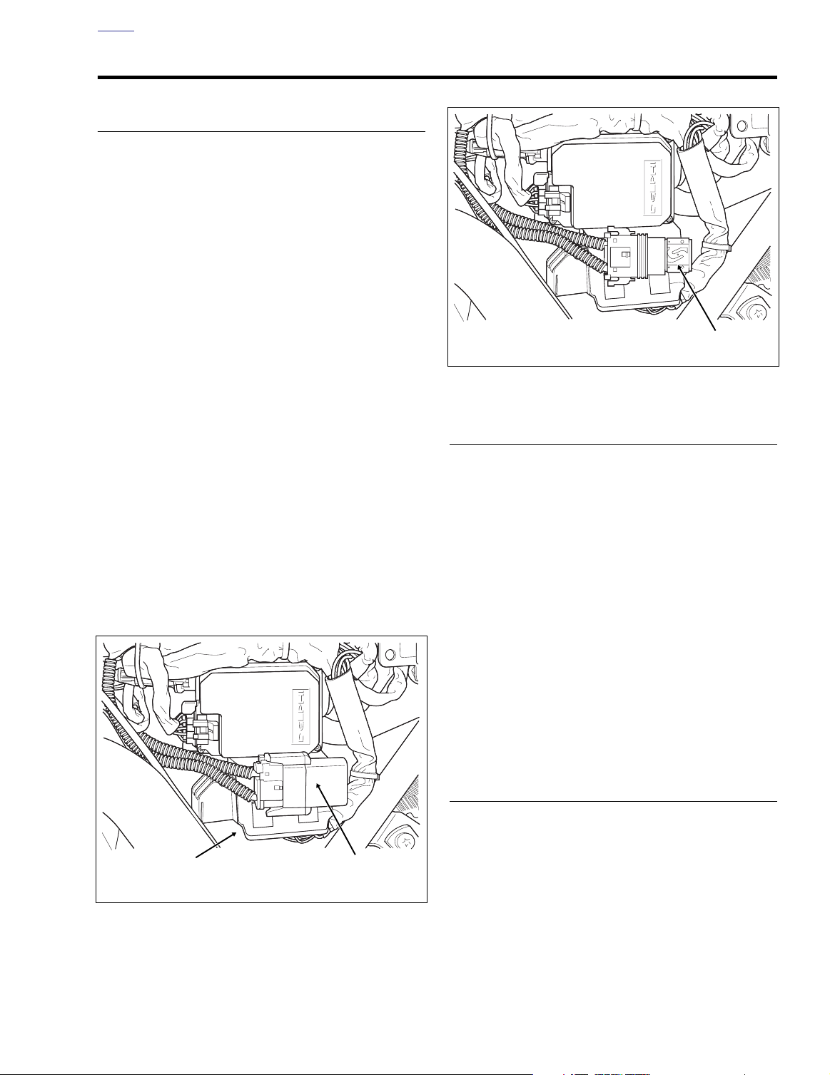
3. Depress latches on maxi-fuse holder and then slide
cover rearward to disengage tongue from groove in fuse
block cover. See Figure 8-2.
4. Pull maxi-fuse from maxi-fuse holder. See Figure 8-3.
Figure 8-3. Remove Maxi-Fuse
INSTALLATION
1. Insert maxi-fuse into maxi-fuse holder. See Figure 8-3.
2. Slide cover forward to engage tongue in groove of fuse
block cover and then insert maxi-fuse holder into cover
until latches engage. See Figure 8-2.
3. Align barbed studs in side cover with grommets in frame
downtubes and push firmly into place (no tools
required).
4. Install left side saddlebag. See Section 2.25 SADDLE-
BAG, INSTALLATION.
Fuse
Block
f2206x8x
Figure 8-2. Remove Left Side Cover
Maxi-Fuse
Cover
MAXI-FUSE HOLDER
REMOVAL
1. Remove maxi-fuse. See MAXI-FUSE, REMOVAL, in this
section.
2. Remove socket terminals from maxi-fuse holder. See
Section B.3 PACKARD ELECTRICAL CONNECTORS,
800 METRI-PACK SERIES.
INSTALLATION
3. Install socket terminals into maxi-fuse holder. See
Section B.3 PACKARD ELECTRICAL CONNECTORS,
800 METRI-PACK SERIES.
4. Install maxi-fuse. See MAXI-FUSE, INSTALLATION, in
this section.
SYSTEM FUSES/RELAYS
REMOVAL
1. Remove maxi-fuse. See MAXI-FUSE, REMOVAL, in this
section.
2. Pull fuse block from tabs on mounting bracket. Tabs on
bracket fit into slots on each side of fuse block cover.
2004 Touring: Electrical 8-5
Page 6
H
OME
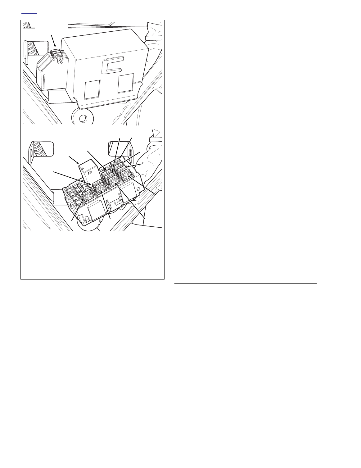
Spare Fuse
Holder
f2203x8x
11
10
Fuse Block
Cover
9
INSTALLATION
1. Install system fuse/relay in fuse block. See lower frame
of Figure 8-4.
NOTE
For FLHR/C/S configuration, see upper frame of Figure 8-1 in
Section 8.1 SPECIFICATIONS.
2. Slide cover over fuse block until slots fully engage tabs
on block. See upper frame of Figure 8-4.
3. Slide fuse block into position on mounting bracket. Tabs
on bracket fit into slots on each side of fuse block cover.
4. Install maxi-fuse. See MAXI-FUSE, INSTALLATION, in
this section.
f2209x8x
7
8
6
5
FUSE BLOCK
REMOVAL
1. Remove system fuses and relay(s). See SYSTEM
FUSES/RELAYS, REMOVAL, in this section.
5. Remove socket terminals from fuse block. See Section
B.3 PACKARD ELECTRICAL CONNECTORS, 280
4
METRI-PACK SERIES.
1
1. Headlamp
2. Ignition
3. Lighting
4. Instruments
5. Brakes/Cruise
6. Radio Memory
Figure 8-4. Fuse Block (FLTR, FLHTC/U)
NOTE
The fuse block cover also serves as the spare fuse holder.
One spare 10 amp and 15 amp fuse are provided.
3. Remove the fuse block cover. Raise lipped side slightly
to disengage slots from tabs on fuse block. See upper
frame of Figure 8-4.
4. Remove system fuse/relay from fuse block. Replace
fuse if the element is burned or broken. Automotive type
ATO fuses are used. See lower frame of Figure 8-4.
NOTE
For FLHR/C/S configuration, see upper frame of Figure 8-1 in
Section 8.1 SPECIFICATIONS.
2
7. Radio Power
8. Accessory
9. Battery
10. Brake Light Relay
11. P&A
3
INSTALLATION
1. Install socket terminals into fuse block. See Section B.3
PA CKARD ELECTRICAL CONNECTORS, 280 METRIPA CK SERIES.
2. Install system fuses and relay(s). See SYSTEM FUSES/
RELAYS, INSTALLATION, in this section.
EFI FUSES
See Section 9.2 ELECTRICAL BRACKET ASSEMBLY, EFI
FUSES.
8-6 2004 Touring: Electrical
Page 7
H
f2191x8x
Ignition Control Module
Connector [10]
OME
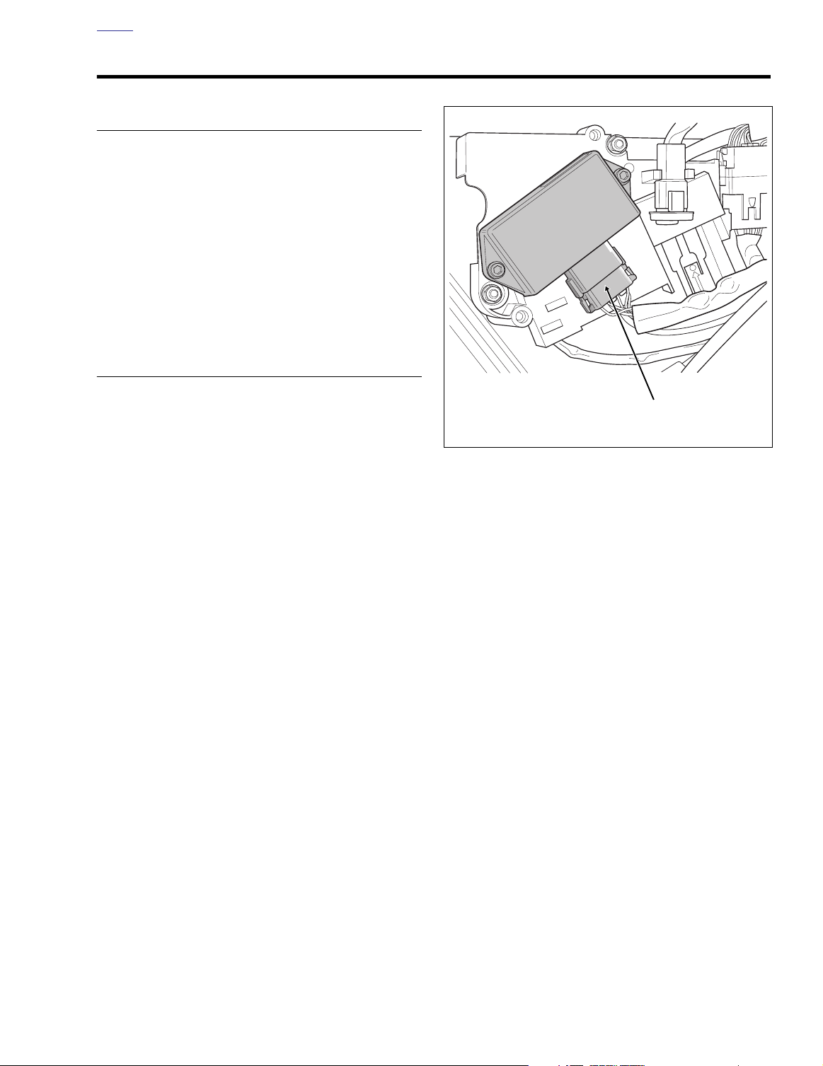
IGNITION CONTROL MODULE (CARBURETED) 8.4
REMOVAL
1. Remove right side saddlebag. See Section 2.25 SAD-
DLEBAG, REMOVAL.
2. Gently pull side cover from frame downtubes (no tools
required).
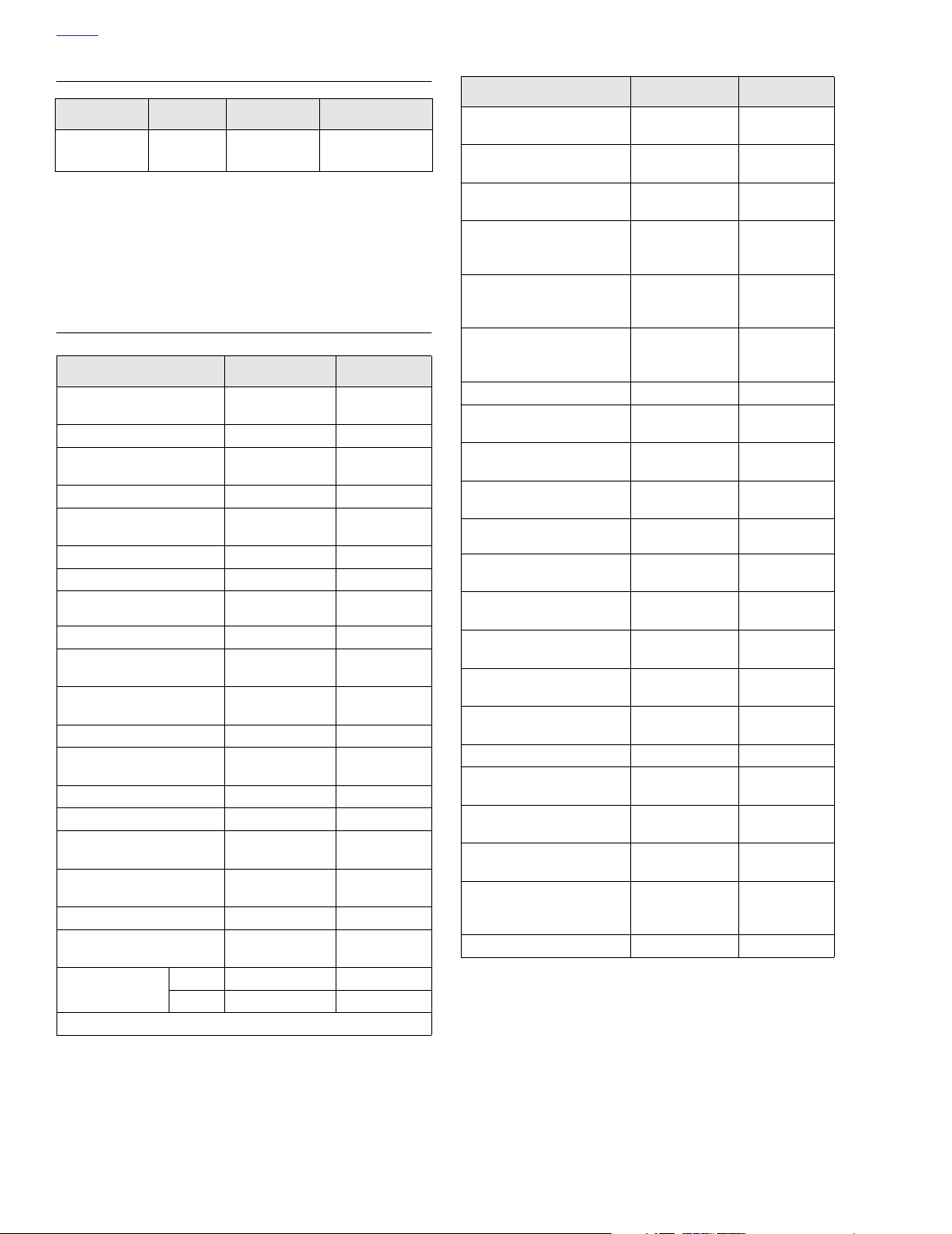
3. Depress external latches and use a rocking motion to to
remove electrical connector. See Figure 8-5.
4. Remove two socket screws to detach ignition control
module from electrical bracket.
INSTALLATION
1. Align holes in ignition control module with those in electrical bracket. Install two socket screws and tighten to
50-60
in-lbs
(5.7-6.8 Nm).
2. Align tabs on socket housing with grooves on pin housing and push connector halves together until latches
click.
3. Align barbed studs in side cover with grommets in frame
downtubes and push firmly into place (no tools required).
Figure 8-5. Electrical Bracket (Under Right Side Cover)
4. Install right side saddlebag. See Section 2.25 SADDLE-
BAG, INSTALLATION.
2004 Touring: Electrical 8-7
Page 8
H
OME
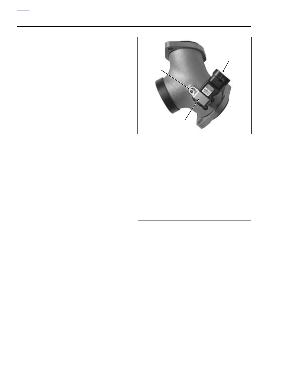
SENSORS (CARBURETED) 8.5
MANIFOLD ABSOLUTE PRESSURE SENSOR
MAP Sensor
Removal
1. Partially remove fuel tank. See Section 4.7 FUEL TANK
(CARBURETED), PA RTIAL REMOVAL, FLHT/C, or
FLHR/S.
2. Pull external latch outward and use rocking motion to
remove electrical connector.
3. Remove T20 TORX screw to release retaining clip from
intake manifold. See Figure 8-6.
T20 TORX
Screw
4. Carefully pull pressure port (enveloped in rubber seal)
from hole in intake manifold.
5. If reusing sensor, inspect condition of rubber seal.
Replace the seal if it is cut, torn or shows signs of deterioration.
Installation
1. Install rubber seal on pressure port, if removed.
2. With port side down, slide end of retaining clip in slot at
side of sensor. Aligning hole in retaining clip with
threaded hole in intake manifold, carefully press pressure port into bore,
Retaining
Clip
Figure 8-6. Intake Manifold
3. Install T20 TORX screw and tighten to 25-35
4.0 Nm). See Figure 8-6.
4. Align latch on socket housing with locking tab on pin
housing and push connector halves together until latch
clicks.
5. Install fuel tank. See Section 4.7 FUEL TANK (CARBU-
RETED), INSTALLATION (AFTER PARTIAL REMOVAL),
FLHT/C, or FLHR/S.
in-lbs
(2.8-
CRANKSHAFT POSITION SENSOR
See Section 9.3 SENSORS, CRANKSHAFT POSITION
SENSOR.
8-8 2004 Touring: Electrical
Page 9
H
8316
f1925x8x
Front
Rear
OME
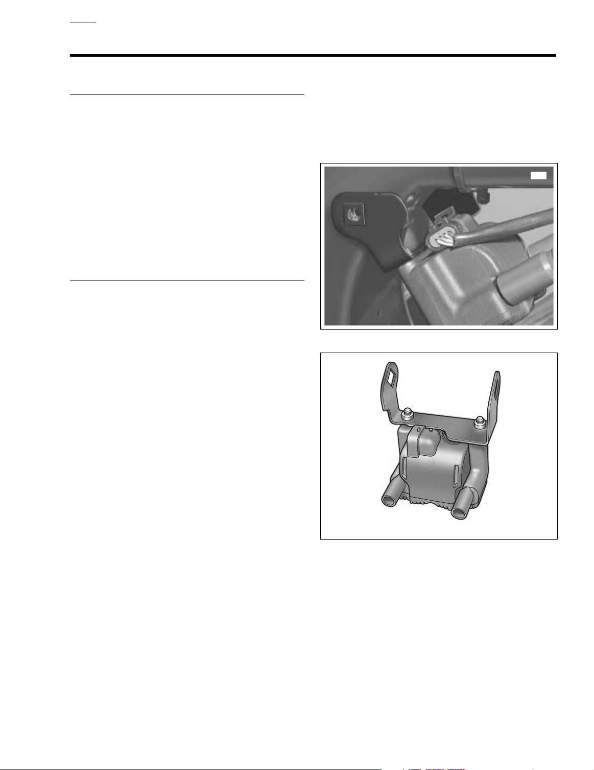
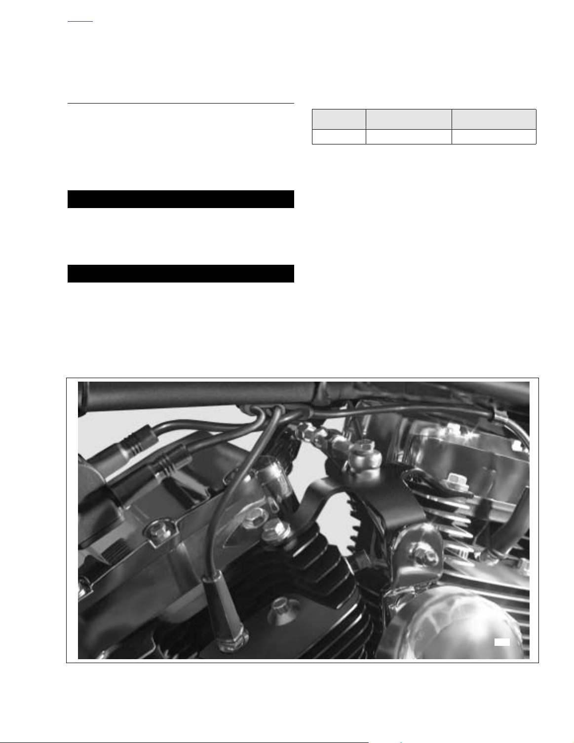
IGNITION COIL 8.6
REMOVAL
1. Partially remove fuel tank. For carbureted models, see
Section 4.7 FUEL TANK (CARBURETED), PA RT IAL
REMOVAL, FLHT/C or FLHR/S. For fuel injected mod-
els, see Section 9.4 FUEL TANK (FUEL INJECTED),
PA RTIAL REMOVAL, FLHT/C/U/I, FLTRI or FLHR/C/S/I.
2. Unplug spark plug cables from ignition coil towers.
3. Pull external latch outward and use rocking motion to
remove electrical connector from left side of ignition coil.
4. Pull sides of ignition coil bracket outward to remove from
bosses of front fuel tank mount. See Figure 8-7.
5. Remove two socket screws to free ignition coil from
bracket.
INSTALLATION
1. Align holes in
Properly positioned, connector pin housing should be
positioned at cut in bracket. Install two socket screws
and tighten to 84-144
8-8.
2. With the coil towers facing rear of vehicle, hold ignition
coil and bracket at bottom of frame backbone. Pull sides
of bracket outward and install on bosses of front fuel
tank mount. See Figure 8-7.
3. Install electrical connector on left side of ignition coil.
Align latch on socket housing with locking tab on pin
housing and push connector halves together until latch
clicks.
4. Install spark plug cable to front cylinder onto left side coil
tower. Verify that spark plug cable is captured in doublesided cable clip at bottom left side of frame backbone.
Install
new
See Figure 8-10.
5. Install spark plug cable to rear cylinder onto right side
coil tower. Verify that spark plug cable is captured in two
single-sided cable clips at bottom left side of frame backbone. Install
missing. See Figure 8-10.
new
ignition coil with holes in bracket.
in-lbs
(9.5-16.3 Nm). See Figure
cable clip on T-stud if damaged or missing.
new
cable clips on T-studs if damaged or
6. Install fuel tank. For carbureted models, see Section 4.7
FUEL TANK (CARBURETED), INSTALLATION (AFTER
PA RTIAL REMOVAL), FLHT/C or FLHR/S. For fuel
injected models, see Section 9.4 FUEL TANK (FUEL
INJECTED), INSTALLATION (AFTER PARTIAL
REMOVAL), FLHT/C/U/I, FLTRI or FLHR/C/S/I.
Figure 8-7. Remove Ignition Coil Bracket From Vehicle
Figure 8-8. Install Bracket to Ignition Coil
2004 Touring: Electrical 8-9
Page 10
H
OME
SPARK PLUGS/SPARK PLUG CABLES 8.7
SPARK PLUGS
Inspect spark plugs at 5000 miles (8,000 km) and replace at
10,000 miles (16,000 km).
The number 6R12 plug is supplied as original equipment and
is the only plug that should be used. The resistor plug
reduces radio interference created by the ignition system and
will not adversely affect performance or fuel economy.
REMOVAL
1. Remove spark plug cables. See SPARK PLUG CABLES
on the next page.
2. Remove spark plug using a 5/8 inch spark plug socket.
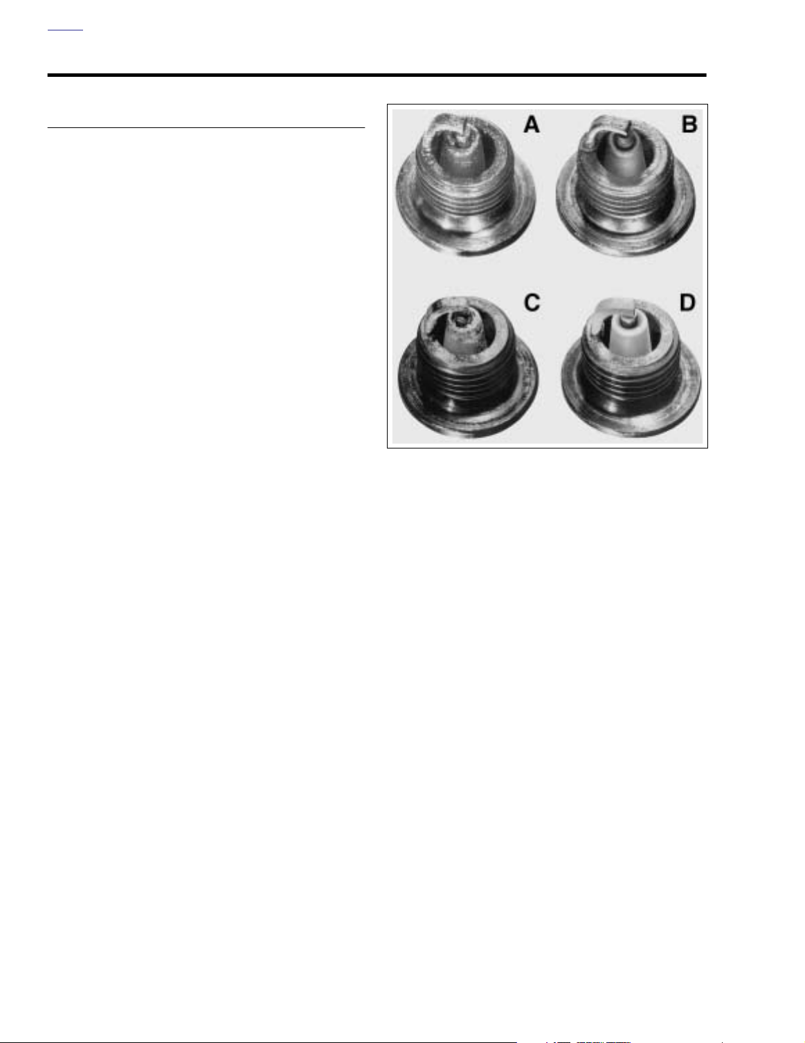
INSPECTION
See Figure 8-9. Examine plugs as soon as they have been
removed. The deposits on the plug base are an indication of
the plug efficiency and are a guide to the general condition of
rings, valves, carburetor and ignition system.
a. A wet black and shiny deposit on plug base, elec-
trodes and ceramic insulator tip indicate an oil
fouled plug. The condition may be caused by worn
rings and pistons, loose valves or seals, weak battery or faulty ignition.
b. A dry fluffy or sooty black deposit indicates a too
rich carburetor air-fuel mixture or long periods of
engine idling. Excessive use of the enrichener may
also cause this condition.
c. An overheated plug can be identified by a light
brown, glassy deposit. This condition may be
accompanied by cracks in the insulator or by erosion of the electrodes. This condition is caused by
too lean an air-fuel mixture, a hot running engine,
valves not seating or improper ignition timing. The
glassy deposit on the spark plug is a conductor
when hot and may cause high speed misfiring. A
plug with eroded electrodes, heavy deposits or a
cracked insulator should be replaced.
d. A plug with white, yellow or light tan to rusty brown
powdery deposit indicates balanced combustion.
The deposits may be cleaned off at regular intervals
if desired.
CLEANING
Figure 8-9. Types of Plug Base Deposits
2. Use a thin file to flatten spark plug electrodes. A spark
plug with sharp edges on its electrodes requires 25%40% less firing voltage than one with rounded edges.
3. Adjust spark plug gap. See ADJUSTMENT below.
ADJUSTMENT
Use only a wire-type gauge. Bend the outside electrode so
only a slight drag on the gauge is felt when passing it
between electrodes. Never make adjustments by bending the
center electrode. Set gap on all plugs at 0.038-0.043 in.
(0.97-1.09 mm).
INSTALLATION
1. Before installing spark plugs, check condition of threads
in cylinder head and on plug. If necessary soften deposits with penetrating oil and clean out with a thread
chaser.
2. Apply a very light coating of ANTISEIZE LUBRICANT to
spark plug threads. Install spark plug. Tighten spark plug
to 12-18 ft-lbs (16-24 Nm).
1. Degrease firing end of spark plug using ELECTRICAL
CONTACT CLEANER. Dry spark plug with compressed
air.
8-10 2004 Touring: Electrical
If a torque wrench is not available, finger-tighten spark
plug and then using a spark plug wrench, tighten plug an
additional 1/4-turn.
Page 11
H
OME
3. Connect spark plug cables to spark plugs. Make sure
boots/caps are secured properly.
4. Check engine idle speed, and adjust if necessary.
SPARK PLUG CABLES
Resistor-type high-tension cables have a carbon-impregnated fabric core (instead of solid wire) for radio noise suppression and improved reliability of electronic components.
Use the exact replacement cable for best results.
REMOVAL
1WARNING1WARNING
Never disconnect a spark plug cable with the engine running. Doing so will result in an electric shock from the
ignition system that could result in death or serious
injury.
CAUTION
When disconnecting a spark plug cable from the spark
plug terminal, always grasp and pull on the rubber boot
at the end of the cable assembly (as close to the spark
plug terminal as possible). Pulling on the cable portion
will damage the carbon core.
1. Disconnect spark plug cables from ignition coil and
spark plug terminals.
INSPECTION
1. Check cables for cracks or loose terminals.
2. Check spark plug cable resistance with an ohmmeter.
Resistance must be as follows:
Table 8-1. Spark Plug Cable Resistance
Position
Front /Rear 20 Inches (508 mm) 5,000 - 11,666
3. Replace cables that are worn or damaged, or that do not
meet resistance specifications.
4. Check cable boots/caps for cracks or tears. Also check
for loose fit on ignition coil and spark plugs. Replace
boots/caps if defects are noted.
Cable Length Resistance (Ohms)
INSTALLATION
1. Connect spark plug cables to spark plugs.
2. Install spark plug cable to front cylinder onto left side coil
tower. Verify that spark plug cable is captured in doublesided cable clip at bottom left side of frame backbone.
Install
new
cable clip on T-stud if damaged or missing.
See Figure 8-10.
3. Install spark plug cable to rear cylinder onto right side
coil tower. Verify that spark plug cable is captured in two
single-sided cable clips at bottom left side of frame backbone. Install
missing. See Figure 8-10.
new
cable clips on T-studs if damaged or
Figure 8-10. Spark Plug Cable Clips (Left Side View)
8497
2004 Touring: Electrical 8-11
Page 12
H
OME
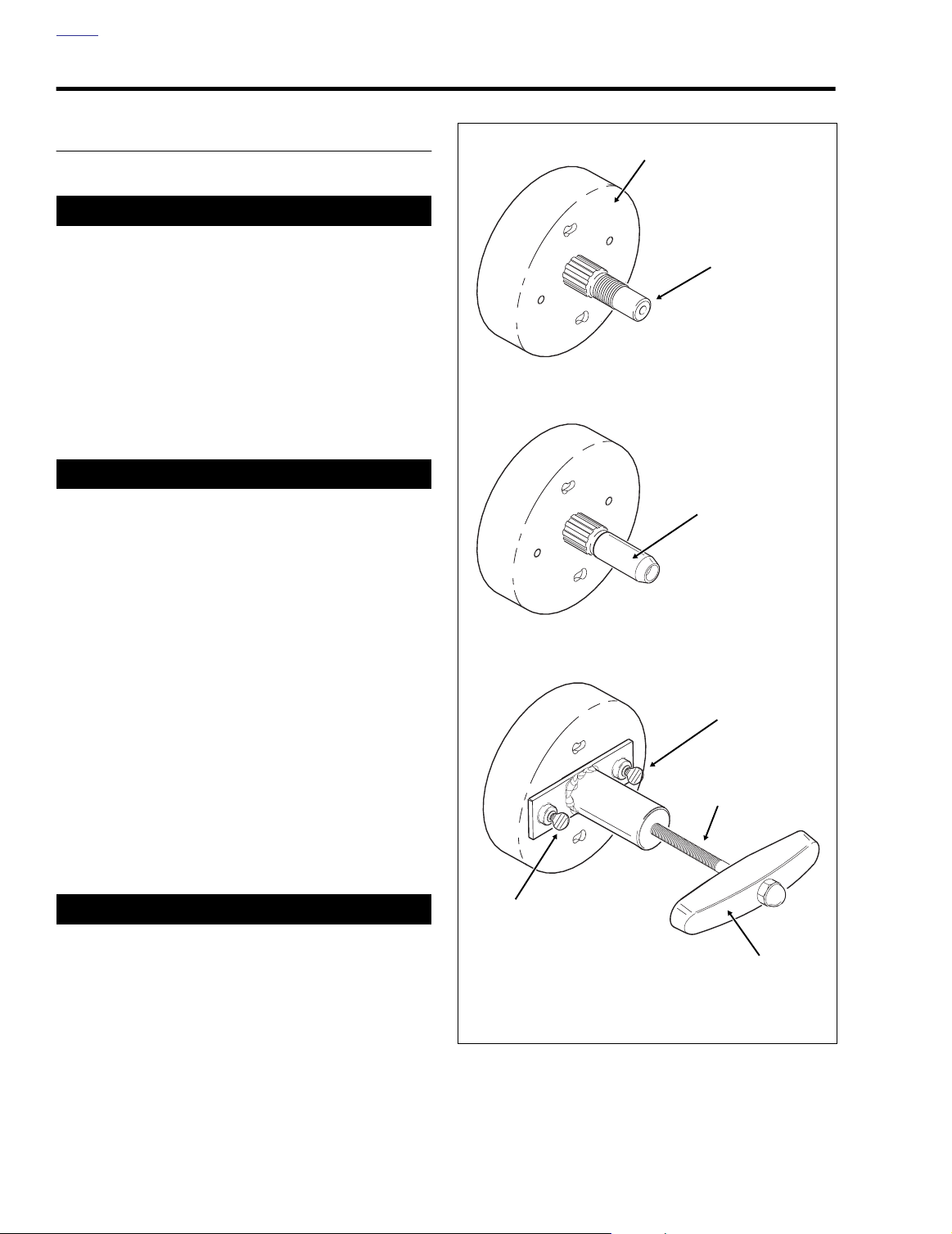
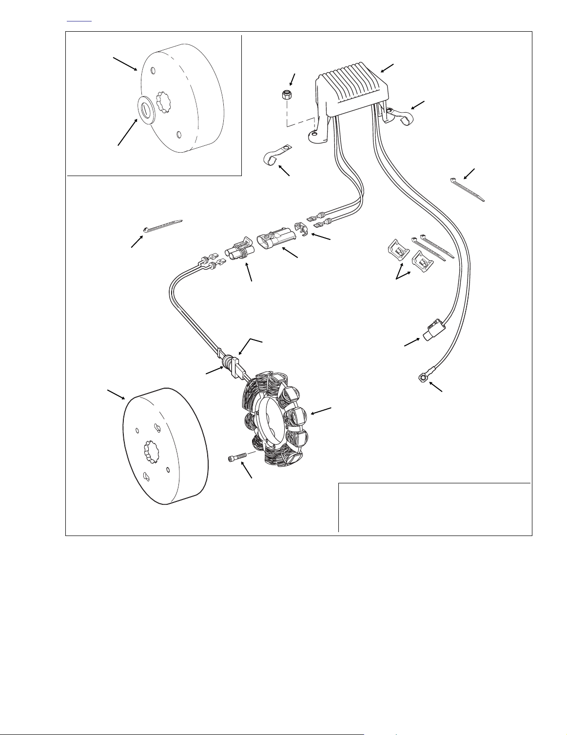
ALTERNATOR/STATOR 8.8
REMOVAL
Rotor
1. Remove seat. See Section 2.24 SEAT, REMOVAL.
1WARNING1WARNING
f2120x8x
To protect against shock and accidental start-up of vehicle, disconnect the negative battery cable before proceeding. Inadequate safety precautions could result in
death or serious injury.
2. Unthread bolt and remove battery negative cable (black)
from battery negative (-) terminal.
3. Remove the primary chaincase cover. Remove the
clutch, primary chain, compensating sprocket and shaft
extension as a single assembly. See Section 6.5 PRI-
MARY CHAINCASE, REMOVAL, steps 3-15.
4. Remove the alternator rotor spacer, if present.
1CAUTION
The high-output rotor is used on fuel injected vehicles,
FLHR/C/S/I excepted. Since the high-output rotor contains magnets that are considerably more powerful than
those used on low-output rotors, the ROTOR REMOVER/
INSTALLER and SHAFT PROTECTOR SLEEVE (HD-
41771) must be used to prevent parts damage and possi-
ble hand injury during removal and installation.
5. Remove the rotor as follows:
High Output Rotor - 45 Amp
a. Verify that threads of engine sprocket shaft are
clean, especially of old Loctite material. Thread the
Shaft Protector Sleeve onto the shaft. See Figure 8-
11.
b. Tu rn thumbscrews of Rotor Remover/Installer into
threaded holes in rotor face.
c. Rotate handle of forcing screw in a clockwise direc-
tion to remove rotor from shaft.
Engine
Sprocket Shaft
1. Clean Sprocket Shaft Threads.
Shaft Protector
Sleeve
2. Install Shaft Protector Sleeve.
Thumbscrew
Forcing Screw
Low Output Rotor - 38 Amp
CAUTION
Do not strike or drop rotor. Damage to magnet adhesive
may result in rotor failure.
a. Fabricate wire hooks or use the ends of two allen
wrenches to carefully pull rotor at holes in rotor
face.
b. Pull rotor from stator. Magnets in rotor cause some
resistance during removal.
8-12 2004 Touring: Electrical
Thumbscrew
Handle
3. Install Rotor Remover/Installer.
Rotate Handle in a Clockwise Direction.
Figure 8-11. Remove Rotor from Engine Sprocket Shaft
Page 13
H
OME
Stator
Connector [46]
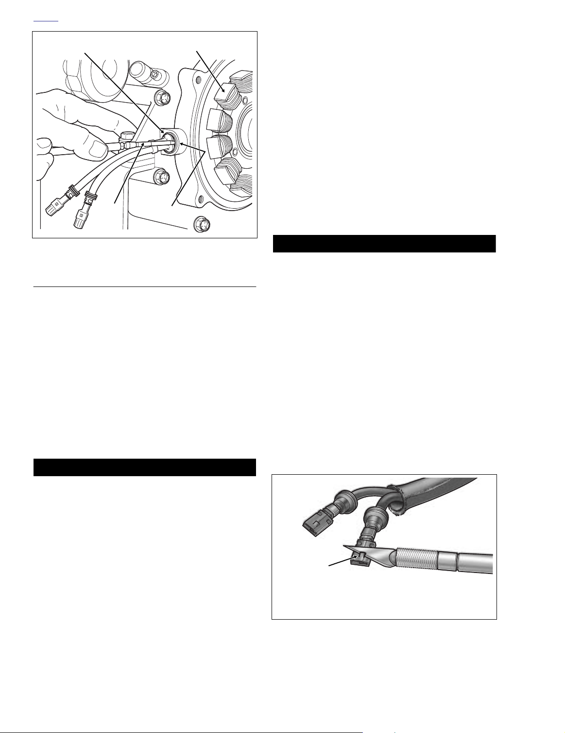
12. Using a T27 TORX drive head, remove four screws to
free stator from crankcase. Discard screws.
13. Using point of awl, carefully lift capped rib on grommet
away from crankcase and then insert into bore between
grommet and casting. See Figure 8-14. Tilt awl slightly
squirting isopropyl alcohol or glass cleaner into opening.
Repeat this step at one or two other locations around
grommet.
14. While pushing on capped rib from outside of crankcase,
draw grommet through bore by pulling on cable stop with
needle nose pliers. Rock grommet back and forth to
facilitate removal, if necessary. Exercise caution to avoid
damaging ribs on grommet if stator is to be reused.
15. Draw stator cables and socket terminals through crankcase bore. For best results, feed one cable and socket
terminal through at a time.
f2256x8x
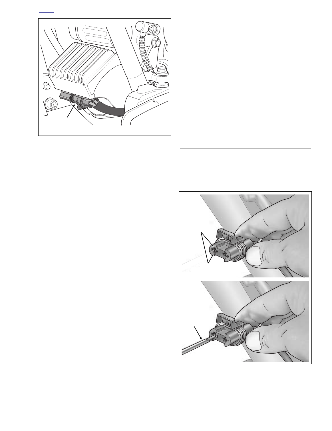
Figure 8-12. Voltage Regulator (Left Side View)
6. Locate stator connector [46], 2-place Packard, fixed to
bracket at bottom of voltage regulator. Cut small cable
strap and slide connector toward left side of motorcycle
to release groove from tongue on bracket. Raise the
external latch and separate pin and socket halves. See
Figure 8-12.
7. Remove locknut from left side leg of voltage regulator.
Loosen right side locknut. Raise voltage regulator as
necessary to free left side leg from stud on lower frame
crossmember.
8. Remove P-clip from stud. Remove P-clip from cable conduit.
9. Draw cable conduit and connector to rear of front engine
stabilizer link and then up to area in front of primary
chaincase.
10. Depress tangs inside socket housing and back out sockets through wire end of connector. Proceed as follows:
a. Looking into the socket housing, take note of the
cavity on each side of the terminal. See upper frame
of Figure 8-13.
b. Gently insert pick (Snap-On TT600-3) into the cavity
about 1/4 inch (6.4 mm) or until it stops, and pivot
the side of the pick toward the terminal body.
Repeat step on other cavity. See lower frame of Fig-
ure 8-13.
c. Gently tug on cable to pull terminal from chamber. If
terminal is still locked, one or both tangs are not
fully depressed. Repeat steps 10(b) and 10(c) as
necessary.
d. Repeat procedure to release second terminal.
CLEANING AND INSPECTION
1. Check inside of rotor and remove any metal fragments
captured by magnets.
2. Clean the rotor using a petroleum solvent. Clean the stator and grommet by wiping it with a clean cloth.
f1912x8x
Cavity
Terminal A
f1911x8x
Pick
11. Remove conduit from cables. For best results, pull one
cable and socket terminal through conduit at a time.
Figure 8-13. Remove Socket Terminals
2004 Touring: Electrical 8-13
Page 14
H
OME
Capped
Rib
Awl
Figure 8-14. Remove Grommet From Crankcase
Opening
Stator
f1634x8x
INSTALLATION
1. From inside crankcase, feed socket terminals and stator
cables through hole in crankcase. For best results, feed
one cable and socket terminal through at a time.
2. Thorougly lubricate grommet with isopropyl alcohol or
glass cleaner. Ribs of grommet must be clean and free
of dirt and oily residue.
3. Carefully grasp cable stop behind grommet with a needle nose pliers. Push grommet into crankcase bore while
carefully pulling on outside cable. Installation is complete when cable stop contacts casting and capped rib of
grommet exits crankcase bore.
4. If necessary, carefully run awl around edge of capped rib
so that it rests flat against seating surface on crankcase.
NOTE
The Shaft Protector Sleeve not only protects the threads from
the splines of the rotor, but acts as a guide to ensure that the
rotor is properly centered.
b. Center ball on forcing screw in recess at end of
engine sprocket shaft. Rotate the handle of the tool
in a counterclockwise direction to ease rotor into
position over stator.
c. Loosen thumbscrews and remove Rotor Remover/
Installer. Remove Shaft Protector Sleeve.
d. Install the shaft extension on the engine sprocket
shaft. (No alternator rotor spacer is provided.)
Low Output Rotor - 38 Amp
a. Slide rotor over stator with the concave side
inboard.
1CAUTION
When installing rotor, keep fingers away from edge that
mates with crankcase. Since rotor is magnetized, as it
nears the crankcase it may be pulled in with considerable force, resulting in pinched fingers or other hand
injury.
b. See inset of Figure 8-16. Install the 0.020 inch
(0.508 mm) thick alternator rotor spacer and the
shaft extension on the engine sprocket shaft.
7. Install conduit onto cables. For best results, feed one
socket terminal and cable through conduit at a time.
8. Install sockets into stator/voltage regulator connector as
follows:
a. Using a fingernail or a thin flat blade, like that on an
X-Acto knife, carefully bend the tangs outward away
from each terminal body. See Figure 8-15.
b. Feed each socket into wire end of stator/voltage
regulator connector until it “clicks” in place.
CAUTION
Do not reuse T27 TORX screws. The threads of the
screws contain a locking compound in pellet form. When
the screw is started, the pellet breaks releasing the compound.
5. Using a T27 TORX drive head, install four
fasten stator to crankcase. Alternately tighten screws to
55-75
in-lbs
(6.2-8.5 Nm).
6. Install the rotor as follows:
new
screws to
High Output Rotor - 45 Amp
a. Install the Shaft Protector Sleeve and Rotor
Remover/Installer, if removed. See Figure 8-11.
8-14 2004 Touring: Electrical
X-Acto Knife
Tang
f1913x8x
Figure 8-15. Bend Tangs Outward
Page 15
H
OME
Rotor
Alternator Rotor Spacer
0.020 Inch (0.508 mm) Thick
f2221x8x
Cable Strap
Stator Connector
f2119x8x
38 AMP
Connector [46]
Stator
Socket
Housing
Flange
Locknut
P-Clamp
Pin
Housing
Secondary
Lock
Cable Straps
and Anchors
Lower Frame Tube
Voltage
Regulator
P-Clamp
Anchored
Cable Strap
Brake Pedal
Weldment
Cable Stop
Grommet
Rotor
T27 TORX
Screw
NO
Alternator Rotor Spacer
Figure 8-16. Stator/Voltage Regulator Assemblies - 45 AMP
c. Verify that sockets will not back out of chambers. A
slight tug on each cable will confirm that it is locked.
9. Feed connector and cable conduit under front engine
stabilizer link and then forward along outboard side of
voltage regulator leg. See Figure 8-12.
Voltage Regulator
Connector [77]
Stator
38 Amp:
FLHR, FLHRI, FLHRCI, FLHRS, FLHRSI, FLHT, FLHTC
45 Amp:
FLHTI, FLHTCI, FLHTCUI, FLTRI
Ring Terminal
10. Install P-clip on cable conduit approximately five inches
(127 mm) from socket housing. Slide P-clip over left side
stud on lower frame crossmember. Properly oriented, Pclip is positioned at front of stud with the open side up
and angled so that it is inline with the lower rail of the
engine guard.
2004 Touring: Electrical 8-15
Page 16

H
OME
11. Raise voltage regulator as necessary to install left side
leg onto stud. Install locknut and tighten to 70-100
in-lbs
(7.9-11.3 Nm).
12. Tighten right side locknut to 70-100
in-lbs
(7.9-11.3
Nm).
13. Mate pin and socket halves of stator connector [46], 2-
place Packard. At bottom of voltage regulator, slide connector toward right side of motorcycle until groove fully
engages tongue on bracket. Install
new
cable strap capturing bracket, connector and cable loop at rear of connector. See Figure 8-12.
14. Install the clutch, primary chain, compensating sprocket
and shaft extension as a single assembly. Install the primary chaincase cover. See Section 6.5 PRIMARY
CHAINCASE, INSTALLATION, steps 9-33.
15. Insert bolt through battery negative cable (black) into
threaded hole of battery negative (-) terminal. Tighten
bolt to 60-96
in-lbs
(6.8-10.9 Nm).
16. Install seat. See Section 2.24 SEAT, INSTALLATION.
8-16 2004 Touring: Electrical
Page 17

H
f2220x8x
Left
Side
Right
Side
Ring Terminal
Stator
Connector [46]
Voltage Regulator
Connector [77]
Anchored
P-Clip
OME
VOLTAGE REGULATOR 8.9
REMOVAL
1. Remove maxi-fuse. See Section 8.3 SYSTEM FUSES,
MAXI-FUSE, REMOVAL.
2. Moving to right side of motorcycle, remove socket head
screw (with captive washer) to release ring terminal from
weld nut at front of transmission exhaust bracket.
3. Locate voltage regulator connector [77], 1-place Deutsch, just below the transmission exhaust bracket.
Depress external latch to separate pin and socket housings.
4. Cut cable strap to free voltage regulator cables from
front anchor installed on T-stud at top of lower frame
tube.
5. Cut cable strap to free voltage regulator cables from
inboard side of rear brake pedal weldment.
6. Draw voltage regulator cables forward allowing ring terminal and Deutsch socket housing to hang at rear of
lower frame crossmember.
7. Locate stator connector [46], 2-place Packard, fixed to
f2256x8x
bracket at bottom of voltage regulator. Cut small cable
strap and slide connector toward left side of motorcycle
to release groove from tongue on bracket. Raise the
external latch and separate pin and socket halves. See
Figure 8-17.
Stator
Connector [46]
Figure 8-17. Voltage Regulator (Left Side View)
Crankshaft
Position Sensor
Connector [79]
Figure 8-18. Voltage Regulator (Rear View)
8. Locate crankshaft position sensor connector [79], 2place Mini-Deutsch, also fixed to bracket at bottom of
voltage regulator. Push connector toward right side of
motorcycle to disengage small end of slot on attachment
clip from T-stud on bracket. Lift connector off T-stud.
9. Remove locknuts from studs on lower frame crossmember. Lift voltage regulator off studs to remove from
motorcycle. Note that right side P-clip is anchored to leg
of voltage regulator. See Figure 8-18.
2004 Touring: Electrical 8-17
Page 18

H
OME
Crankshaft Position Sensor Connector
[79] and Cable Strap Not Shown
Front Cable Strap
Anchor
Stator
Connector [46]
Figure 8-19. Voltage Regulator Cable Routing (Right Side View)
NOTE
For instructions on removing and installing wire terminals in
stator connector [46], 2-place Packard, see Section 8.8
ALTERNATOR/STATOR, REMOVAL and INSTALLATION,
steps 10 and 8, respectively. To remove and install cable in
voltage regulator connector [77], 1-place Deutsch, see Section B.1 DEUTSCH ELECTRICAL CONNECTORS, 1-PLACE
CABLE CONNECTOR.
Rear Brake Pedal
Weldment
f2281x8x
INSTALLATION
1. If removed, slide P-clip over left side stud on lower frame
crossmember. Properly oriented, P-clip is positioned at
front of stud with the open side up and angled so that it
is inline with the lower rail of the engine guard.
2. Slide voltage regulator over studs feeding two cables
downward at rear of lower frame crossmember. Allow
ring terminal and Deutsch socket housing to hang
beneath motorcycle.
8-18 2004 Touring: Electrical
Page 19

H
OME
3. Install locknuts on studs and tighten to 70-100
(7.9-11.3 Nm).
4. Locate crankshaft position sensor connector [79], 2place Mini-Deutsch, at rear of voltage regulator. Place
large end of slot on attachment clip over T-stud on
bracket at bottom of voltage regulator. Push connector
toward left side of motorcycle to engage small end of
slot.
5. Mate pin and socket halves of stator connector [46], 2place Packard. At bottom of voltage regulator, slide connector toward right side of motorcycle until groove fully
engages tongue on bracket. Install
turing bracket, connector and cable loop at rear of connector.
6. Route voltage regulator cables rearward following
inboard side of lower frame tube. Capturing voltage regulator cables and lower frame tube, install
strap through opening in rear brake pedal weldment.
See Figure 8-19. Cut any excess cable strap material.
NOTE
Cable strap also captures branch of main harness leading to
oil pressure sender and crankshaft position sensor connectors.
7. Position voltage regulator cables over front anchor
installed on T-stud at top of lower frame tube. Thread
new
cable strap through eyelets in anchor to capture
cables. Cut any excess cable strap material.
new
cable strap cap-
new
in-lbs
cable
8. Mate pin and socket housings of voltage regulator connector [77], 1-place Deutsch, just below the transmission
exhaust bracket.
9. Install socket head screw (with captive washer) to fasten
ring terminal to weld nut at front of transmission exhaust
bracket. Tighten screw to 20-35
10. Install maxi-fuse. See Section 8.3 SYSTEM FUSES,
MAXI-FUSE, INSTALLATION.
11. Load test charging system.
in-lbs
(2.3-4.0 Nm).
NOTE
Cable strap anchor also captures rear brake line and branch
of main harness leading to oil pressure sender and crankshaft position sensor connectors.
2004 Touring: Electrical 8-19
Page 20

H
OME
BATTERY 8.10
GENERAL
All batteries are permanently sealed, maintenance-free,
valve-regulated, lead/calcium and sulfuric acid batteries. The
batteries are shipped pre-charged and ready to be put into
service. Do not attempt to open these batteries for any reason.
1WARNING1WARNING
All batteries contain electrolyte. Electrolyte is a sulfuric
acid solution that is highly corrosive and can cause
severe chemical burns. Avoid contact with skin, eyes,
and clothing. Avoid spillage. Always wear protective face
shield, rubberized gloves and protective clothing when
working with batteries. A warning label is attached to the
top of the battery. See Figure 8-20. Never remove warning label from battery. Failure to read and understand all
precautions contained in warning label before performing any service on batteries could result in death or serious injury. See Figure 8-21.
Table 8-2. Antidote
External - Flush with water
Internal - Drink large quantities of milk or
water, followed by milk of magnesia, vegetable oil or beaten eggs.
Call doctor immediately.
Eyes - Flush with water, get immediate
medical attention.
Warning
Label
r
o
d without charge
ls
a
f
i
r
o
e
t
e
e
t
a
t
a
a
m
d
d
n
i
m
m
o
e
o
r
ll be replac e
v
r
f
6
i
f
t
r
s
c
e
s
e
h
e
h
t
h
t
f
t
f
t
n
e
f
n
A
o
d
o
o
.
e
e
m
s
m
s
b
WARRANTY AND ADJUSTMENT POLICY
h
2
a
t
6
o
1
h
n
t
r
battery will
c
o
p
o
r
i
d
d
u
m
This battery wi
h
n
e
e
p
s
s
u
g
2
a
n
r
r
o
1
f
a
e
a
h
t
f
c
e
h
i
m
n
r
c
h
k
t
u
u
r
r
o
p
e
n
o
c
i
s
e
-
rchase , the
w
l
h
a
e
t
c
n
i
h
i
h
r
t
c
h
w
u
-
r
t
e
t
r
u
f
e
v
e
u
r
p
o
v
b
f
o
e
s
,
o
h
f
s
h
t
t
e
o
h
t
n
d
m
n
o
,
i
n
e-counter pu
t
o
s
a
m
r
e
m
f
d
MADE IN USA
-th
e
c
t
a
a
l
over
p
e
e
c
r
i
r
u
e
p
n
b
r
e
a
h
l
t
u
nly for the period of ownership based on
r
g
o
e
e
v
r
e
d
h
t
e
h
t
t
y
a
r
b
t
o
d
y
r
l
e
p
o
d
r
i
t
rranty. This wa rran ty
o
c
v
e
l
wa
s
e
i
r
d
e
n
p
a
o
D
r
-
p
Y
m
i
E
E
L
K
I
R
U
E
A
A
D
A
H
W
M
IL
M
o
h
t
o
t
a
r
n
e
.
e
s not transferable
b
i
e
v
s
u
m
j
u
e
b
r
a
f
r
o
o
e
t
s
c
u
e
l
e
g
N
e
1
n
O
,
e
0
S
2
D
3
I
1234567890
V
5
I
A
.
A
.
W
,
S
.
E
U
N
JA FE MA AP MY JU JY AU SE OC NO DE
.
O
N
T
R
PA
f1730x8x
Figure 8-20. Maintenance-Free Battery
VOLTMETER TEST
See Ta b l e 8-3. The voltmeter test provides a general indicator of battery condition. Check the voltage of the battery to
verify that it is in a 100% fully charged condition. If the open
circuit (disconnected) voltage reading is below 12.6V, charge
the battery and then recheck the voltage after the battery has
set for one to two hours. If the voltage reading is 12.8V or
above, perform the LOAD TEST described in this section.
Contents
are Corrosive.
Wear
Safety Glasses.
8-20 2004 Touring: Electrical
Contents
are Explosive.
Keep
Flames Away.
Figure 8-21. Battery Warning Label
Read
Instructions.
Keep Away
From Children.
f2180x3x
Page 21

H
1WARNING1WARNING
CAUTION
OME
Table 8-3. Voltmeter Test
Voltage (OCV) State of Charge
12.8 100%
12.6 75%
12.3 50%
12.0 25%
11.8 0%
DISCONNECTION AND REMOVAL
1. Remove seat. See Section 2.24 SEAT, REMOVAL.
1WARNING1WARNING
Always disconnect the negative battery cable first. If the
positive cable should contact ground with the negative
cable installed, the resulting sparks may cause a battery
explosion which could result in death or serious injury.
2. Unthread bolt and remove battery negative cable (black)
from battery negative (-) terminal.
3. Unthread bolt and remove battery positive cable (red)
from battery positive (+) terminal.
4. Using a T-40 TORX drive head, loosen bolt to move lip of
hold-down clamp off edge of battery. Remove battery
from battery box.
BATTERY CHARGING
SAFETY PRECAUTIONS
Never charge a battery without first reviewing the instructions
for the charger being used. In addition to the manufacturer’s
instructions, follow these general safety precautions:
Always wear proper eye, face and hand protection.
●
●
Always charge batteries in a well-ventilated area.
Turn the charger “OFF” before connecting the leads
●
to the battery to avoid dangerous sparks.
●
Never try to charge a visibly damaged or frozen battery.
● Connect the charger leads to the battery; red posi-
tive (+) lead to the positive (+) terminal and black
negative (–) lead to the negative (–) terminal. If the
battery is still in the vehicle, connect the negative
lead to the chassis ground. Be sure that the ignition
and all electrical accessories are turned off.
● Make sure that the charger leads to the battery are
not broken, frayed or loose.
● If the battery becomes hot, or if violent gassing or
spewing of electrolyte occurs, reduce the charging
rate or turn off the charger temporarily.
● Always turn the charger “OFF” before removing
charger leads from the battery to avoid dangerous
sparks.
CHARGING BATTERY
CLEANING AND INSPECTION
1. Battery top must be clean and dry. Dirt and electrolyte
on top of the battery can cause battery to self-discharge.
Clean battery top with a solution of baking soda (sodium
bicarbonate) and water (5 teaspoons baking soda per
quart or liter of water). When the solution stops bubbling,
rinse off the battery with clean water.
2. Clean cable connectors and battery terminals using a
wire brush or sandpaper. Remove any oxidation.
3. Inspect the battery screws, clamps and cables for breakage, loose connections and corrosion. Clean clamps.
4. Check the battery posts for melting or damage caused
by overtightening.
5. Inspect the battery for discoloration, raised top or a
warped or distorted case, which might indicate that the
battery has been frozen, overheated or overcharged.
6. Inspect the battery case for cracks or leaks.
Charge the battery if any of the following conditions exist:
● Vehicle lights appear dim.
● Electric starter sounds weak.
● Battery has not been used for an extended period of
time.
Always charge the battery in a well ventilated area.
Explosive hydrogen gas escapes from the battery during
charging. Keep open flames, electrical sparks and smoking materials away from the battery at all times. Failure
to do so could result in death or serious injury.
If the battery releases an excessive amount of gas during charging, decrease the charging rate. If the battery
gets hotter than 110˚F. (43˚C) during charging, discontinue charging and allow the battery to cool. Overheating
may result in plate distortion, internal shorting, dryout or
other damage.
2004 Touring: Electrical 8-21
Page 22

H
OME
Table 8-4. Battery Charging Rates/Estimated Times
Battery
Amp-Hour
TOURING
28
The figures listed above assume that the battery is charging at room temperature. If warmer than room temperature, use a slightly shorter
charging time. If colder, use a slightly longer charging time.
The use of constant current chargers to charge sealed maintenance-free batteries is not recommended. Any overcharge will cause dryout and premature battery failure. If a constant current charger is the only type available, do not exceed the charge times listed above and
do not continue charging the battery if it gets hot. When charging, never exceed 15 volts for more than 30 minutes.
1. Perform a voltmeter test to determine the state of
charge. See VOLTMETER TEST in this section. If battery needs to be charged, proceed to step 2.
Always remove the battery from the motorcycle before
charging. Accidental electrolyte leakage will damage
motorcycle parts.
2. Remove the battery from the motorcycle. See DISCON-
NECTION AND REMOVAL in this section. Place the bat-
tery on a level surface.
Always unplug or turn OFF the battery charger before
connecting the charger clamps to the battery. Connecting clamps with the charger ON could cause a spark
resulting in a battery explosion. A battery explosion may
rupture the battery case causing a discharge or spray of
sulfuric acid which could result in death or serious
injury.
Do not reverse the charger connections described in the
following steps or the charging system of the motorcycle
could be damaged.
Voltage Reading % of Charge
State of Charge
12.8 V100% ----
12.6 V 75% 2.5 hours 1.25 hours 45 minutes 25 minutes
12.3 V 50% 5 hours 2.5 hours 1.5 hours 50 minutes
12.0 V 25% 7.5 hours 3.75 hours 2.25 hours 70 minutes
11.8 V 0% 10 hours 5 hours 3 hours 1.5 hours
CAUTION
3
Amp Charger6Amp Charger10Amp Charger20Amp Charger
NOTE
If the battery is still in the vehicle, connect the negative lead
to the chassis ground. Be sure that the ignition and all electrical accessories are turned off.
5. Step away from the battery and turn on the charger. See
the charging instructions in Ta bl e 8-4.
1WARNING1WARNING
Always unplug or turn OFF the battery charger before
disconnecting the charger clamps from the battery. Disconnecting clamps with the charger ON could cause a
spark resulting in a battery explosion. A battery explo-
1WARNING1WARNING
CAUTION
sion may rupture the battery case causing a discharge
or spray of sulfuric acid which could result in death or
serious injury.
6. After the battery is fully charged, disconnect the black
battery charger lead to the negative (–) terminal of the
battery.
7. Disconnect the red battery charger lead to the positive
(+) terminal of the battery.
8. Mark the charging date on the battery.
9. Perform a load test to determine the condition of the battery. See LOAD TEST on this page.
LOAD TEST
3. Connect the red battery charger lead to the positive (+)
terminal of the battery.
4. Connect the black battery charger lead to the negative
(–) terminal of the battery.
The load test measures battery performance under full current load and is the best indicator of battery condition. To
load test the battery, proceed as follows:
8-22 2004 Touring: Electrical
Page 23

H
CAUTION
1WARNING1WARNING
1WARNING1WARNING
CAUTION
OME
CAUTION
Load testing a discharged battery can result in permanent battery damage.
1. Always fully charge the battery before testing or test
readings will be incorrect. See CHARGING BATTERY, in
this section. Load testing a discharged battery can also
result in permanent battery damage.
2. After charging, allow battery to stand for at least one
hour before testing.
1WARNING1WARNING
Always turn the battery load tester OFF before connecting the tester cables to the battery terminals. Connecting
tester cables with the load tester ON could cause a spark
resulting in a battery explosion. A battery explosion may
rupture the battery case causing a discharge or spray of
sulfuric acid which could result in death or serious
injury.
3. Connect tester leads to battery posts and place induction pickup over negative (black) cable. See Figure 8-22.
Load
Tester
To avoid load tester and/or battery damage, do not leave
the load tester switch turned ON for more than 20 seconds.
4. Referencing Table 8-4, load battery at 50% of CCA rating using the load tester. Voltage reading after 15 seconds should be 9.6V or more at 70°F. (21°C).
Table 8-5. Battery Load Test
COLD CRANKING
AMPERAGE (CCA)
TOURING 300 150
Always turn the battery load tester OFF before disconnecting the tester cables from the battery terminals. Disconnecting tester cables with the load tester ON could
cause a spark resulting in a battery explosion. A battery
explosion may rupture the battery case causing a discharge or spray of sulfuric acid which could result in
death or serious injury.
5. Install the battery on the motorcycle. See INSTALLA-
TION AND CONNECTION below.
100% 50%
Induction
Figure 8-22. Load Test Battery
Pickup
BATTERY CABLE ROUTING
Hole on left side of frame crossmember is used for
cruise cable routing only. Use of the hole for battery
cable routing can result in contact with hot exhaust pipe
causing melting or burning of the cable insulation, damage that can lead to driveability problems or fire hazard,
conditions which could result in death or serious injury.
Route all battery cables through opening between tray of battery box and bottom of frame cross member. Cables should
be positioned as shown in Figure 8-23.
INSTALLATION AND CONNECTION
1. Place the fully charged battery into the battery box, terminal side forward.
f1731x8x
Connect the cables to the correct battery terminals or
damage to the motorcycle electrical system will occur.
2004 Touring: Electrical 8-23
Page 24

H
OME
1WARNING1WARNING
Always connect the positive battery cable first. If the
positive cable should contact ground with the negative
cable installed, the resulting sparks may cause a battery
explosion which could result in death or serious injury.
CAUTION
Overtightening bolts can damage battery terminals.
1. Insert bolt through battery positive cable (red) into
threaded hole of battery positive (+) terminal. Tighten
bolt to 60-96 in-lbs (6.8-10.9 Nm).
2. Insert bolt through battery negative cable (black) into
threaded hole of battery negative (-) terminal. Tighten
bolt to 60-96 in-lbs (6.8-10.9 Nm).
3. Apply a light coat of petroleum jelly or corrosion retardant material to both battery terminals.
4. Rotate the hold-down clamp so that the lip (with rubber
pad) rests on the edge of the battery. Using a T-40 TORX
drive head, tighten the clamp bolt to 15-20 ft-lbs (20-27
Nm).
5. Install seat. See Section 2.24 SEAT, INSTALLATION.
f2268x8x
Frame
Cross Member
Frame Hole
Cruise Cable
Routing Only
f1732x8x
Effect of Temperature on
Battery Self-Discharge Rate
100%
C
A
75%
50%
P
A
C
I
T
Y
0
at 105°F
MONTHS OF STAND
3691215
at 77
°
F
Figure 8-24. Battery Self-Discharge Rate
STORAGE
1WARNING1WARNING
Store the battery out of the reach of children. Inadequate
safety precautions could result in death or serious
injury.
CAUTION
The electrolyte in a discharged battery will freeze if
exposed to freezing temperatures. Freezing may crack
the battery case and buckle battery plates.
If the motorcycle will not be operated for several months,
such as during the winter season, remove the battery from
the motorcycle and fully charge. See CHARGING BATTERY
in this section.
Positive
Battery Cable
Negative
Battery Cable
Main Power
To Maxi-Fuse
Figure 8-23. Battery Cable Routing (Right Side View)
Self-discharge is a normal condition and occurs continuously
at a rate that depends on the ambient temperature and the
battery’s state of charge. Batteries discharge at a faster rate
at higher ambient temperatures. To reduce the self-discharge
rate, store battery in a cool (not freezing), dry place. See Fig-
ure 8-24.
Charge the battery every month if stored at temperatures
below 60˚ F. (16˚ C). Charge the battery more frequently if
stored in a warm area above 60˚ F. (16˚ C).
NOTE
The GLOBAL BATTERY CHARGER (Part No. 99863-01)
may be used to maintain battery charge for extended periods
of time without risk of overcharging or boiling.
When returning a battery to service after storage, refer to the
instructions under CHARGING BATTERY in this section.
8-24 2004 Touring: Electrical
Page 25

1WARNING1WARNING
f1268x2x
Wider
Ear
Wire Form
Loop
Bulb
Socket
Wire Form
Loop
Hinge
Slots
Lense
Backplate
H
OME
HEADLAMP (FLHR/C/S, FLHT/C/U) 8.11
HEADLAMP ASSEMBLY
REMOVAL
1. Remove the Phillips screw at the bottom of the headlamp door (chrome ring). Remove the headlamp door.
2. Proceed as follows:
FLHT/C/U: Remove the four TORX screws to free the
headlamp housing from the fairing.
FLHR/C/S: Remove the eight Phillips screws to free the
headlamp housing from the headlamp nacelle.
3. Squeeze the two external tabs (if present) to remove the
wire connector at the back of the headlamp bulb.
Remove the headlamp housing assembly from the vehicle.
INSTALLATION
1. Install the wire connector at the back of headlamp bulb.
2. Proceed as follows:
FLHT/C/U: Align holes in headlamp housing with those
in fairing (headlamp door bracket at bottom). Install the
four TORX screws.
FLHR/C/S: Align holes in headlamp housing with those
in headlamp nacelle (headlamp door bracket at bottom).
Install the eight Phillips screws.
3. Fit the square-shaped portion of the headlamp door
spring into the slot at the top of the headlamp housing
and then snap the headlamp door (chrome ring) into
place. Install Phillips screw at the bottom of the headlamp door and tighten to 9-18 in-lbs (1.0-2.0 Nm).
5372
Retaining
Ring Screws
Figure 8-26. Headlamp Lense/Bulb Assembly
(Rear View)
HEADLAMP BULB REPLACEMENT
The headlamp is a replaceable bulb (and not a sealed
beam). Made of quartz glass filled with Halogen gas, the bulb
is very delicate and must be handled with care.
NOTE
When replacement is required, use only the specified bulb
available from your Harley-Davidson dealer. Improper wattage or bulb may cause charging system problems.
1. Remove the Phillips screw at the bottom of the headlamp door (chrome ring). Remove the headlamp door.
2. Remove the three Phillips screws to free the retaining
ring from the headlamp housing. See Figure 8-25. Carefully remove the lense and bulb assembly.
3. Squeeze the two external tabs (if present) to remove the
wire connector at the back of the headlamp bulb.
Remove the lense and bulb assembly from the vehicle.
4. Remove the rubber boot at the back of the lense.
5. Push down on loops of wire form to free ends from slots
on lense insert. See Figure 8-26. Use hinge to swing
wire form out of the way.
Figure 8-25. Remove Retaining Ring Screws
(FLHT/C/U Model Shown)
The bulb contains Halogen gas under pressure. Wear
adequate eye protection and handle the bulb carefully.
Inadequate safety precautions could result in death or
serious injury.
2004 Touring: Electrical 8-25
Page 26

H
OME
f1285b2x
A
Figure 8-27. Check Headlamp Alignment
6. Remove and discard bulb.
CAUTION
Never touch the quartz bulb with your fingers. Fingerprints will etch the glass and cause premature bulb failure. Always wrap the bulb in paper or a clean dry cloth
during handling.
7. Install new bulb in lense. Rotate bulb as necessary so
that backplate makes full contact with lense insert.
NOTE
Wider ear on backplate should point toward the top of the
lense. The top can be determined by the position of the headlamp door bracket, which is at the bottom (on the opposite
side).
8. Use hinge to place wire form over socket at back of bulb.
Press down on loops so ends of wire form engage slots
on lense insert.
9. Install rubber boot at back of lense tucking outer edge
into headlamp housing.
10. Install the wire connector at the back of headlamp bulb.
11. Fit lense and bulb assembly into headlamp housing.
Align holes in retaining ring with those in headlamp
housing. Install the three Phillips screws.
12. Fit the square-shaped portion of the headlamp door
spring into the slot at the top of the headlamp housing
and then snap the headlamp door (chrome ring) into
place. Install Phillips screw at the bottom of the headlamp door and tighten to 9-18 in-lbs (1.0-2.0 Nm).
25 ft.
(7.62m)
5374
Headlamp
Door
Slot
5372
Vertical
Adjuster Screw
Horizontal
Adjuster Screw
(Headlamp Door Removed for Illustration Purposes)
Figure 8-28. Adjust Headlamp Alignment
(FLHT/C/U Model Shown)
A
HEADLAMP ADJUSTMENT
Check headlamp beam for proper height and lateral alignment.
8-26 2004 Touring: Electrical
Page 27

H
OME
1WARNING1WARNING
DO NOT modify the ignition/light key switch wiring to
disable the automatic-on headlamp feature. High visibility is an important safety consideration for motorcycle
riders. Ensure that the headlamp is on at all times. Failure to do so could result in death or serious injury.
1. Verify correct front and rear tire inflation pressure.
2. Place the motorcycle on a level floor or pavement in an
area with minimum light.
3. See Figure 8-27. Point the front of the motorcycle toward
a screen or wall which is 25 feet (7.62 m) from where
patch of front tire contacts floor (i.e. - directly below front
axle).
4. Draw a horizontal line on screen or wall that is exactly
the same height above the floor as the headlamp center.
5. Have a person whose weight is roughly the same as that
of the principal rider sit on the motorcycle seat. The
weight of the rider will compress the vehicle suspension
slightly.
6. Stand the motorcycle upright with both tires resting on
the floor and with the front wheel held in straight alignment (directly forward).
7. Turn the Ignition/Light Key Switch to IGNITION. Set the
Light Switch on the left handlebar to Hi(gh) beam.
8. Check the light beam for proper height alignment. The
center of the main beam of light should be even with the
horizontal line on the screen or wall.
9. Check the light beam for proper lateral alignment. The
main beam of light should be directed straight ahead
(i.e., equal area of light to right and left of center).
NOTE
The headlamp adjustment can be performed without removing the headlamp door (chrome ring).
10. If the headlamp alignment requires adjustment, use slots
in headlamp door to insert Phillips screw driver between
headlamp housing and rubber gasket. Turn the vertical
adjuster screw as necessary to adjust the headlamp vertically. Turn the horizontal adjuster screw to adjust the
headlamp horizontally. See Figure 8-28.
2004 Touring: Electrical 8-27
Page 28

H
OME
HEADLAMP (FLTR) 8.12
HEADLAMP ASSEMBLY
REMOVAL
1. Remove the outer fairing. See Section 2.30 UPPER
FAIRING/WINDSHIELD (FLTR), OUTER FAIRING,
REMOVAL.
2. Move outer fairing assembly to bench area.
3. Squeeze two external tabs to disconnect headlamp harness connectors from bulb contacts.
CAUTION
Wrap electrical tape around blade of screwdriver to prevent damage to tabs of transparent lense cover.
4. From inboard side of outer fairing, release top of transparent lense cover from slots in fairing by gently
depressing two tabs with blade of screwdriver. Depress
two bottom tabs and remove lense cover from fairing.
5. Depress mounting clips on three hex adjuster studs and
pull headlamp assembly out front of outer fairing. See
Figure 8-29.
Plastic
Boss
Hex Adjuster
Stud
Bulb
Housing
Figure 8-30. Remove Retainer to Release Bulb
Plastic
Retainer
f1546x8x
INSTALLATION
1. Align hex adjuster studs with plastic bosses on inboard
side of outer fairing. Push headlamp assembly into position until mounting clips engage bosses.
2. Carefully snap bottom tabs of transparent lense cover
into bottom slots of outer fairing. Carefully snap upper
tabs of lense cover into upper slots of fairing.
3. Install headlamp harness connectors onto bulb contacts.
4. Install the outer fairing. See Section 2.30 UPPER FAIR-
ING/WINDSHIELD (FLTR), OUTER FAIRING, INSTAL-
LATION.
Mounting
Clip
Figure 8-29. Depress Mounting Clips
8-28 2004 Touring: Electrical
f1544x8x
HEADLAMP BULB REPLACEMENT
The headlamp is a replaceable bulb (and not a sealed
beam). Made of quartz glass filled with Halogen gas, the bulb
is very delicate and must be handled with care.
NOTE
When replacement is required, use only the specified bulb
available from your Harley-Davidson dealer. Improper wattage or bulb may cause charging system problems.
REMOVAL
1. Remove the outer fairing. See Section 2.30 UPPER
FAIRING/WINDSHIELD (FLTR), OUTER FAIRING,
REMOVAL.
2. Move outer fairing assembly to bench area.
Page 29

H
CAUTION
1WARNING1WARNING
OME
f1545x8x
Wider
Ear
Slot
Tabs
Figure 8-31. Install New Bulb in Bulb Housing
3. Squeeze two external tabs to disconnect headlamp harness connector from bulb contacts.
4. Remove rubber boot at back of bulb housing.
5. Rotate plastic retainer in a counter-clockwise direction to
remove from bulb housing flange. See Figure 8-30.
INSTALLATION
Never touch the quartz bulb with your fingers. Fingerprints will etch the glass and cause premature bulb failure. Always wrap the bulb in paper or a clean dry cloth
during handling.
1. Install new bulb in bulb housing. Orient bulb so that
wider ear on backplate is topside and then push bottom
of backplate so that tabs on outboard side fit snugly in
slot of bulb housing. See Figure 8-31.
2. Place plastic retainer over bulb housing flange and
rotate in a clockwise direction until tight. See Figure 8-
30.
3. Install rubber boot over retainer until flush with base of
bulb socket.
4. Connect headlamp harness connector to bulb contacts.
5. Install the outer fairing. See Section 2.30 UPPER FAIR-
ING/WINDSHIELD (FLTR), OUTER FAIRING, INSTAL-
LATION.
HEADLAMP ADJUSTMENT
Check headlamp beam for proper height and lateral alignment.
1WARNING1WARNING
The bulb contains Halogen gas under pressure. Wear
adequate eye protection and handle the bulb carefully.
Inadequate safety precautions could result in death or
serious injury.
6. Remove and discard bulb.
6421 6420
Hex Adjuster
LEFT SIDE RIGHT SIDE
DO NOT modify the ignition/light key switch wiring to
disable the automatic-on headlamp feature. High visibility is an important safety consideration for motorcycle
riders. Ensure that the headlamp is on at all times. Failure to do so could result in death or serious injury.
Hex Adjuster
Figure 8-32. Headlamp Adjustment (FLTR)
2004 Touring: Electrical 8-29
Page 30

H
OME
1. Verify correct front and rear tire inflation pressure.
2. Place the motorcycle on a level floor or pavement in an
area with minimum light.
3. See Figure 8-27. Point the front of the motorcycle toward
a screen or wall which is 25 feet (7.62 m) from where
patch of front tire contacts floor (i.e. - directly below front
axle).
4. Draw a horizontal line on screen or wall that is exactly
the same height above the floor as the headlamp center.
5. Have a person whose weight is roughly the same as that
of the principal rider sit on the motorcycle seat. The
weight of the rider will compress the vehicle suspension
slightly.
6. Stand the motorcycle upright with both tires resting on
the floor and with the front wheel held in straight alignment (directly forward).
7. Turn the Ignition/Light Key Switch to IGNITION. Set the
Light Switch on the left handlebar to Hi(gh) beam.
8. Check the light beam for proper height alignment. The
center of the main beam of light should be even with the
horizontal line on the screen or wall.
9. Check the light beam for proper lateral alignment. The
main beam of light should be directed straight ahead
(i.e., equal area of light to right and left of center).
10. Locate the hex adjusters near the bottom edge of the
inner fairing. See Figure 8-32. Tu rning the adjusters
causes the double headlamp housing to pivot around its
upper mount.
11. Using a 4.5 mm, 1/4 inch drive socket (Snap-On
TMM4.5) and flexible driver (Snap-On TM62B), adjust
the headlamp horizontally by turning either the left or
right side adjuster. Turn both adjusters equally to adjust
the headlamp vertically. Adjuster rotation moves the
headlamp beam as follows:
Table 8-6. FLTR Hex Adjuster Rotation
Hex Adjuster Rotation
Left Only CW
Right Only CCW
Left Only CCW
Right Only CW
Left and Right Equally CW Upward
Left and Right Equally CCW Downward
CW= Clockwise CCW= Counter-Clockwise
Beam
Movement
To t he Right
To the Left
8-30 2004 Touring: Electrical
Page 31

H
Lamp
Index Tab
Nesting Ring
Index Tab
f2272x8x
OME
PASSING LAMPS 8.13
ADJUSTMENT
1. Using a long shank ball end socket (Snap-on® FABL5),
remove two screws to release turn signal lamp from
mounting bracket. See Figure 8-33. Use hole in passing
lamp bracket to access inboard screw.
2. Insert flare nut socket (Snap-on® FRX181) at bottom of
turn signal mounting bracket and loosen locknut on stud.
3. Move lamp and swivel block to obtain the desired position.
NOTE
Passing lamps should shine straight ahead with the center of
the main light beam even with a horizontal line drawn on a
wall 25 feet (7.6 m) away. The line on the wall should be at
the same height as the center of the passing lamps with the
rider mounted.
4. Using flare nut socket, tighten locknut to 18 ft-lbs (24.4
Nm).
Passing
Lamp
8820
Door
Figure 8-34. Install Nesting Ring at Back of
Passing Lamp Bulb
5. Using long shank ball end socket, start two screws to
secure turn signal lamp to mounting bracket. Verify that
conduit fits in slot at back of bracket and is not pinched
as screws are tightened.
Bracket
Screw
Mounting
Bracket
Conduit
Turn Signal
Lamp
Figure 8-33. Passing Lamp and Turn Signal
Door
Screw
PASSING LAMP BULB
REMOVAL
1. Loosen passing lamp door screw as required to pull
lamp door from lip of lamp housing. See Figure 8-33.
2. Pull socket terminals from spade contacts at back of
lamp.
3. Remove nesting ring and discard lamp.
INSTALLATION
1. Place nesting ring at back of new lamp with the concave
side up. See Figure 8-34.
2. Install socket terminals onto spade contacts at back of
lamp.
3. Install lamp fitting nesting ring over edge of lamp housing. Rotate nesting ring so that index tab is aligned with
slot at bottom of lamp housing.
2004 Touring: Electrical 8-31
Page 32

H
OME
Figure 8-35. Inner Fairing (FLHT/C/U)
f2212x8x
Passing Lamp
Connector [73]
f2238x8x
PASSING LAMP
REMOVAL
1. Proceed as follows:
FLHT/C/U: Remove the outer fairing. See Section 2.29
UPPER FAIRING/WINDSHIELD (FLHT/C/U), OUTER
FAIRING/WINDSHIELD, REMOVAL. Locate passing
lamp connector (white 2-place Multilock) below upper
fork bracket. See Figure 8-35.
FLHR/C: Remove the Phillips screw at the bottom of the
headlamp door (chrome ring). Remove the headlamp
door. Remove the eight Phillips screws to free the headlamp housing from the headlamp nacelle. Squeeze the
two external tabs to remove the wire connector at the
back of the headlamp bulb. Remove the headlamp housing assembly from the vehicle. Locate passing lamp connector (white 2-place Multilock). See Figure 8-36.
2. Depress the button on the socket terminal side of the
connector and pull apart the pin and socket halves.
3. Remove terminal of Gray/Black wire from socket housing.
NOTE
For instructions on properly removing wire terminals, see
APPENDIX B.2 AMP MULTILOCK ELECTRICAL CONNEC-
TORS, REMOVING SOCKET/PIN TERMINALS.
Passing Lamp
Switch Connector [109]
Passing Lamp
Connector [73]
Figure 8-36. Headlamp Nacelle (FLHRC)
4. Holding nesting ring in place, rotate lamp so that dot on
lense is at the bottom and index tabs at back engage
slots in nesting ring.
5. Verify that two adhesive foam strips are present on
inboard side of lamp door. Install new foam strips if deteriorated or missing.
6. Install lamp door over lip of lamp housing. Rotate lamp
door so that screw is centered at bottom, and then
tighten door screw until snug.
4. Using a long shank ball end socket (Snap-on® FABL5),
remove two screws to release turn signal lamp from
mounting bracket. See Figure 8-33. Use holes in pass-
ing lamp bracket to access inboard screw.
5. Obtain length of strong flexible wire for use as mechanics wire. Feed wire through opening in socket terminal
and then loop back twisting end until tightly coiled
around longer strand as shown in Figure 8-37.
Mechanics Wire
Socket Terminal
f1418x2x
Figure 8-37. Fix Mechanics Wire to Socket Terminals
8-32 2004 Touring: Electrical
Page 33

H
OME
NOTE
Be sure that mechanics wire is of sufficient strength to pull
terminal through conduit without breaking. Wire length must
also be long enough so that free end is not lost in conduit
when pulled.
6. Carefully pull wire to draw socket terminal through conduit.
7. Unravel mechanics wire to release socket terminal.
8. Insert flare nut socket (Snap-on® FRX181) at bottom of
turn signal mounting bracket and remove locknut from
stud. Remove the turn signal mounting bracket and
clamp block.
9. Remove passing lamp (with Belleville washer and swivel
block) from the passing lamp bracket.
INSTALLATION
1. Lay old passing lamp next to new passing lamp and cut
Gray/Black wire to length.
2. Strip 3/16 inch (4.8 mm) of insulation off new lamp wire
and crimp on new socket terminal.
NOTE
For instructions on crimping wire terminals, see APPENDIX
B.2 AMP MULTILOCK ELECTRICAL CONNECTORS,
CRIMPING INSTRUCTIONS.
3. If removed, slide swivel block and Belleville washer down
Gray/Black wire onto passing lamp stud. Be sure that
rounded side of swivel block and concave side of
Belleville washer face passing lamp.
4. Feed Gray/Black wire of passing lamp through slot at top
of passing lamp bracket and insert threaded stud into
forward slot. Slide clamp block (rounded side up), turn
signal mounting bracket and locknut up Gray/Black wire
onto passing lamp stud at bottom of bracket.
5. Using flare nut socket (Snap-on® FRX181), tighten locknut to 18 ft-lbs (24.4 Nm).
6. Reattach mechanics wire to socket terminal and carefully pull end of mechanics wire to draw socket terminal
back through conduit.
7. Carefully remove mechanics wire to avoid damage to
terminal.
8. Install terminal of Gray/Black wire into socket housing.
11. Using a long shank ball end socket (Snap-on® FABL5),
start two screws to secure turn signal lamp to mounting
bracket. Verify that conduit fits in slot at back of bracket
and is not pinched as screws are tightened. Use holes in
passing lamp bracket to access inboard screw.
12. Proceed as follows:
FLHT/C/U: Route passing lamp conduit upward in front
of chrome skirt and then rearward using relief in upper
outboard corner (in front of fairing bracket). Install the
outer fairing. See Section 2.29 UPPER FAIRING/WIND-
SHIELD (FLHT/C/U), OUTER FAIRING/WINDSHIELD,
INSTALLATION.
FLHR/C: Install wire connector at the back of the headlamp bulb. Align holes in headlamp housing with those in
headlamp nacelle (headlamp door bracket at bottom).
Install eight Phillips screws.
PASSING LAMP BRACKET
REMOVAL
1. Remove passing lamp bracket from motorcycle. Proceed
as follows:
FLHR/C: Remove acorn nuts from fork bracket studs.
All Others: Using a T40 TORX drive head, loosen upper
and lower fork bracket screws.
2. Remove passing lamp bracket from motorcycle.
INSTALLATION
1. Install passing lamp bracket on motorcycle. Proceed as
follows:
FLHR/C: Slide slots of passing lamp bracket onto upper
and lower fork bracket studs. Install acorn nuts on studs.
Alternately tighten acorn nuts to 72-108 in-lbs (8.1-12.2
Nm) using a crosswise pattern.
All Others: Slide slots of passing lamp bracket onto T40
TORX screws in upper and lower fork brackets. Alternately tighten screws to 15-20 ft-lbs (20-27 Nm) using a
crosswise pattern.
NOTE
For instructions on properly installing wire terminals, see
APPENDIX B.2 AMP MULTILOCK ELECTRICAL CONNEC-
TORS, INSTALLING SOCKET/PIN TERMINALS.
9. Mate pin and socket halves of passing lamp connector.
10. Turn Ignition/Light Key Switch to IGNITION and test for
proper operation and alignment. Adjust if necessary.
2004 Touring: Electrical 8-33
Page 34

H
OME
TAIL LAMP ASSEMBLY 8.14
TAIL LAMP
REMOVAL
1. Remove two Phillips screws from lense to release tail
lamp assembly from chrome plastic bracket at back of
rear fender. Carefully pull tail lamp assembly from
bracket. See left side of Figure 8-38.
2. Depress button at bottom of 4-place Multilock socket to
release tail lamp assembly from pin housing. See right
side of Figure 8-38.
INSTALLATION
1. Orient 4-place Multilock socket so that the release button is at the bottom and insert into pin housing until it
“clicks.”
2. Place tail lamp into position against chrome plastic
bracket tucking conduit into space below pin housing
screw. See right side of Figure 8-38.
CAUTION
Over tightening screws can crack the lense or result in
scratching of the fender paint.
3. Align holes in lense with those in chrome plastic bracket
and install two Phillips screws. Tighten screws to 20-24
in-lbs (2.3-2.7 Nm).
4. Turn the Ignition/Light Key Switch to IGNITION and test
lamp for proper operation.
CIRCUIT BOARD/TAIL LAMP BRACKET
REMOVAL
1. Remove two Phillips screws from lense to release tail
lamp assembly from chrome plastic bracket at back of
rear fender. Carefully pull tail lamp assembly from
bracket. See left side of Figure 8-38.
2. Depress button at bottom of 4-place Multilock socket to
release tail lamp assembly from pin housing. See right
side of Figure 8-38.
3. Depress buttons to remove four remaining Multilock
sockets from pin housing. See Figure 8-39.
All remaining release buttons are at the top, with the
exception of the rear fender lights harness socket, where
f2173x8x
Tail Lamp
Assembly
68140-98
Chrome Plastic
Bracket
Figure 8-38. Remove Tail Lamp and Depress Button to Release Socket
Tail Lamp [93]
4-place Multilock
Space
8-34 2004 Touring: Electrical
Page 35

H
CAUTION
H-D
USA
68830-98
f1506x8x
Pin Housing
Circuit Board
OME
Fender Tip
Lamp [45]
Tail Lamp
[93]
Left Turn
Signal Lamp
[18]
Opening
Right Turn
Signal Lamp
[19]
Fender Lights
Harness to
Circuit Board
[94]
f2172x8x
4. Remove large Phillips screw and pull pin housing with
attached circuit board (and gasket) from chrome plastic
bracket. Two tabs at back of pin housing fit into holes in
bracket.
5. Remove chrome plastic bracket. Use both thumbs to
push bracket upward until it becomes free of fender and
then pull out of fender hole.
6. Feed Multilock sockets through openings to inboard side
of bracket. See Figure 8-39. For best results, free the
smaller sockets first.
INSTALLATION
1. Feed Multilock sockets through openings to outboard
side of chrome plastic bracket. See Figure 8-39. For best
results, feed the larger sockets first.
2. Fit bottom of bracket into fender hole and then push
down to align center hole in bracket with clip nut on
fender flange.
3. Place pin housing over circuit board, if removed. See
Figure 8-41.
4. Snap tabs at back of pin housing into holes in plastic
bracket.
Figure 8-39. Rear Fender Lights Assembly
Pick
Tool
Figure 8-40. Release Left Turn Signal Lamp Socket
the button is on the outboard side. To release socket
housings of left and right turn signal lamps, use a pick or
small screwdriver to depress top release button as
shown in Figure 8-40.
Over tightening screw can crack the plastic bracket or
result in scratching of the fender paint.
5. Install large Phillips screw to secure pin housing, circuit
board and plastic bracket to fender flange. Tighten screw
to 40-48 in-lbs (4.5-5.4 Nm).
f1497b8x
Figure 8-41. Place Pin Housing Over Circuit Board
2004 Touring: Electrical 8-35
Page 36

H
OME
6. Install each socket into pin housing until it “clicks.” Install
rear fender tip lamp and both left and right turn signal
lamp sockets so that the release buttons are at the top.
Install the rear fender lights harness socket with the button on the outboard side and the tail lamp socket with
the button at the bottom.
7. To avoid stressing wires, verify that tail lamp conduit is
positioned on the outboard side of the rear fender tip
lamp and left turn signal lamp conduit as shown in Fig-
ure 8-38.
8. Place tail lamp into position against chrome plastic
bracket tucking conduit into space below pin housing
screw.
CAUTION
Over tightening screws can crack the lense or result in
scratching of the fender paint.
9. Align holes in lense with those in chrome plastic bracket
and install two Phillips screws. Tighten screws to 20-24
in-lbs (2.3 - 2.7 Nm).
10. Turn the Ignition/Light Key Switch to IGNITION and test
lamp for proper operation.
8-36 2004 Touring: Electrical
Page 37

H
f2238x8x
Front Fender
Tip Lamp [32]
f2212x8x
Front Fender
Tip Lamp [32]
Used on FLHR Only
OME
FENDER TIP LAMPS 8.15
FRONT FENDER TIP LAMP
REMOVAL
1. Insert blade of small screwdriver into slot at top of fender
tip lamp lense. Rotate end of screwdriver to unsnap
lense from lamp bracket.
2. Remove gasket from fender tip lamp bracket, if present.
3. Holding Keps nuts at inboard side of rear fender, remove
two Phillips screws to release fender tip lamp bracket.
4. Depress button on socket terminal side of black 2-place
Multilock connector to release fender tip lamp assembly
from jumper harness. See Figure 8-44.
INSTALLATION
1. Mate pin and socket halves of black 2-place Multilock
connector to attach front fender tip lamp assembly to
jumper harness. See Figure 8-44.
2. With wires routed along bottom left side, place fender tip
lamp bracket into position aligning holes in bracket with
those in fender.
CAUTION
Over tightening screws can crack the bracket or result in
scratching of the fender paint.
3. Slide Phillips screws through bracket and fender holes
and install Keps nuts. Holding nuts at inboard side of
fender, tighten screws to 20-24 in-lbs (2.3 - 2.7 Nm).
4. Place gasket into position on fender tip lamp bracket, if
present.
5. Insert tab at bottom of lense into slot of fender tip lamp
bracket. Apply thumb pressure at top of lense until it
snaps into place.
6. Turn the Ignition/Light Key Switch to IGNITION and test
lamp for proper operation.
FRONT FENDER TIP LAMP JUMPER HARNESS
REMOVAL
1. Proceed as follows:
FLHT/C/U: Reaching in below the fairing cap on the left
side of the steering head, locate the front fender tip lamp
connector (black 2-place Multilock). See Figure 8-42.
Remove the outer fairing only if necessary. See Section
2.29 UPPER FAIRING/WINDSHIELD (FLHT/C/U),
OUTER FAIRING/WINDSHIELD, REMOVAL.
Figure 8-42. Inner Fairing (FLHT/C/U)
Figure 8-43. Headlamp Nacelle (FLHRC)
FLHR: Remove the Phillips screw at the bottom of the
headlamp door (chrome ring). Remove the headlamp
door. Remove the eight Phillips screws to free the headlamp housing from the headlamp nacelle. Squeeze the
2004 Touring: Electrical 8-37
Page 38

H
OME
two external tabs (if present) to remove the wire connector at the back of the headlamp bulb. Remove the headlamp housing assembly from the vehicle. Locate the
front fender tip lamp connector (black 2-place Multilock).
See Figure 8-43.
2. Depress the button on the socket terminal side of the
connector and pull apart the pin and socket halves.
3. Draw socket connector down to fender area.
4. Carefully cut cable strap to release front fender tip lamp
wires from brake line hose.
5. Remove terminals from socket housing.
NOTE
For instructions on properly removing wire terminals, see
APPENDIX B.2 AMP MULTILOCK ELECTRICAL CONNEC-
TORS, REMOVING SOCKET/PIN TERMINALS.
6. Place the motorcycle on a hydraulic center stand with
the front wheel raised off the ground.
7. Remove the front wheel. See Section 2.3 FRONT
WHEEL, REMOVAL.
8. From inboard side of front fender, remove two nuts to
release trim strip from left side of fender. See Figure 8-
45.
9. Pull wires and Multilock socket terminals through grommet to inboard side of fender. See Figure 8-46. Reaching under left side of fender, release wires from one weld
clip and four metal adhesive clips.
10. Feed wires and Multilock socket terminals through
oblong hole to outboard side of fender.
Fender Tip
Lamp Bracket
Oblong Hole
Tee Bolt
Wire Conduit
f1505x8x
Trim Strip
Figure 8-45. Install Conduit in Trim Strip
Grommet
f1504a8x
LEFT SIDE
Fender Tip
2-Place
Lamp Bracket
Multilock
Connector
Figure 8-44. Fender Tip Lamp Assembly
Brake
Hose
f1503b8x
Socket
Terminals
Figure 8-46. Pull Fender Tip Lamp Wires and Terminals
Through Fender Grommet
11. Insert blade of small screwdriver into slot at top of fender
tip lamp lense. Rotate end of screwdriver to unsnap
lense from lamp bracket.
12. Remove gasket from fender tip lamp bracket, if present.
13. Holding Keps nuts at inboard side of front fender,
remove two Phillips screws to release fender tip lamp
bracket.
8-38 2004 Touring: Electrical
Page 39

H
1WARNING1WARNING
1WARNING1WARNING
1
2
3
4
Fender
Bracket
f2003x8x
Weld
Clip
OME
14. Depress button on socket terminal side of 2-place Multilock connector to release fender tip lamp assembly
from jumper harness. See Figure 8-44.
INSTALLATION
1. See Figure 8-47. Carefully inspect the condition and
security of the four metal adhesive clips in the left side
fender well. Replace the clips if broken, loose or missing.
Proceed as follows:
a. Remove remnants of old clip, as well as all residual
adhesive.
b. Using a soapy Scotch Brite® pad, thoroughly clean
fender well in area of clip.
c. Rinse with clear water and dry with a clean white
cloth. Repeat step until clean cloth shows no evidence of dirt.
d. Swab area with isopropyl alcohol.
e. Obtain new metal adhesive clip (Part No. 10187).
f. Remove paper backing to expose adhesive and
firmly press clip into place.
2. Mate pin and socket halves of 2-place Multilock connector to attach front fender tip lamp assembly to jumper
harness. See Figure 8-44.
3. With wires routed along bottom left side, place fender tip
lamp bracket into position aligning holes in bracket with
those in fender.
Figure 8-47. Four Metal Adhesive Clips
(Left Side Front Fender Well)
11. Install terminals into socket housing.
NOTE
For instructions on properly installing wire terminals, see
APPENDIX B.2 AMP MULTILOCK ELECTRICAL CONNEC-
TORS, INSTALLING SOCKET/PIN TERMINALS.
12. Reaching under left side of fender, route wires of the
jumper harness through one weld clip and four metal
adhesive clips. See Figure 8-47.
CAUTION
Over tightening screws can crack the bracket or result in
scratching of the fender paint.
4. Slide Phillips screws through bracket and fender holes
and install Keps nuts. Holding nuts at inboard side of
fender, tighten screws to 20-25 in-lbs (2.3-2.8 Nm).
5. Place gasket into position on fender tip lamp bracket, if
present.
6. Insert tab at bottom of lense into slot of fender tip lamp
bracket. Apply thumb pressure at top of lense until it
snaps into place.
7. Route wire conduit inside trim strip and slide front tee
bolt over conduit. See Figure 8-45. Ve rify that second
tee bolt is in position at rear of trim strip.
8. Feed Multilock socket terminals and wires through
oblong hole to inboard side of fender.
9. While removing slack from wires on outboard side of
fender, align tee bolts with fender holes. Wtih trim strip
positioned against left side of fender, reach under fender
and install nuts on tee bolts. Alternately tighten nuts to
10-15 in-lbs (1.1-1.7 Nm).
10. Pull Multilock socket terminals and wires through grommet to outboard side of fender. See Figure 8-46.
If any portion of the jumper harness crosses over the riveted fender bracket, contact with the tire can cause chafing or other damage. Damage to the wiring can lead to
loss of lighting while riding, which could result in death
or serious injury.
13. Verify that no portion of the jumper harness crosses over
the riveted fender bracket.
If the height of any metal clip is above the riveted fender
bracket, contact with the tire can cause damage that
results in premature tire failure, which could result in
death or serious injury.
14. Using finger pressure, bend arm of each clip down over
wires so that no portion of the clip is above the height of
the fender bracket.
15. Route socket housing of front fender tip lamp connector
upward behind chrome skirt (FLHT/C/U) or through bottom of headlamp nacelle (FLHR) to area beneath upper
fork bracket. Mate pin and socket halves.
2004 Touring: Electrical 8-39
Page 40

H
OME
NOTE
To connect front fender tip lamp with the outer fairing
installed (FLHT/C/U models), reach in below the fairing cap
on the left side of the steering head.
16. Install the front wheel. See Section 2.3 FRONT WHEEL,
INSTALLATION.
17. Install new cable strap to secure front fender tip lamp
wires to brake line hose. Cut any excess cable strap
material.
18. Proceed as follows:
FLHT/C/U: Install the outer fairing, if removed. See Sec-
tion 2.29 UPPER FAIRING/WINDSHIELD (FLHT/C/U),
OUTER FAIRING/WINDSHIELD, INSTALLATION.
FLHR: Install wire connector at the back of the headlamp bulb. Align holes in headlamp housing with those in
headlamp nacelle. Install eight Phillips screws. Install
the headlamp door (chrome ring) and door screw.
19. Turn Ignition/Light Key Switch to IGNITION and test
lamp for proper operation.
Screwdriver
Lense
f1501x8x
REAR FENDER TIP LAMP
REMOVAL
1. Remove two Phillips screws from lense to release tail
lamp assembly from chrome plastic bracket at back of
rear fender. Carefully pull tail lamp assembly from
bracket.
Rear Fender
Tip Lamp [45]
Opening
Figure 8-48. Depress Button to Release Socket
From Pin Housing
Tail Lamp [93]
f2172x8x
Gasket
TORX
Screws
Fender Tip
Lamp Bracket
f1500x8x
Figure 8-49. Remove Rear Fender Tip Lamp Lense
and Bracket
2. Depress button at bottom of 4-place Multilock socket to
release tail lamp assembly from pin housing. See Figure
8-48.
3. Depress button at top of 3-place Multilock socket to
release fender tip lamp assembly from pin housing.
4. Feed 3-place Multilock socket through opening in
chrome plastic bracket to inboard side of rear fender.
Reaching under left side of rear fender, release conduit
from two cable clips anchored on T-studs.
5. Insert blade of small screwdriver into slot at top of fender
tip lamp lense. Rotate end of screwdriver to unsnap
lense from lamp bracket. See upper frame of Figure 8-
49.
8-40 2004 Touring: Electrical
Page 41

H
CAUTION
OME
Fender
Hole
Fender Tip
Lamp Bracket
Figure 8-50. Feed Fender Tip Lamp Socket and Conduit
Through Fender Hole
6. Remove gasket from fender tip lamp bracket, if present.
See lower frame of Figure 8-49.
7. Holding nuts at inboard side of rear fender, remove two
TORX screws to release fender tip lamp bracket.
8. Draw conduit and 3-place Multilock socket out through
bottom fender hole. See Figure 8-50.
9. Remove terminals from socket housing.
NOTE
For instructions on properly removing wire terminals, see
APPENDIX B.2 AMP MULTILOCK ELECTRICAL CONNEC-
TORS, REMOVING SOCKET/PIN TERMINALS.
f1499x8x
NOTE
For instructions on properly installing wire terminals, see
APPENDIX B.2 AMP MULTILOCK ELECTRICAL CONNEC-
TORS, INSTALLING SOCKET/PIN TERMINALS.
4. Feed 3-place Multilock socket and conduit through bottom fender hole. See Figure 8-50.
5. Place fender tip lamp bracket into position aligning holes
in bracket with those in fender. Slide TORX screws
through bracket and fender holes and install nuts.
6. Place gasket into position on fender tip lamp bracket, if
present. See lower frame of Figure 8-49.
7. Insert tab at bottom of lense into slot of fender tip lamp
bracket. Apply thumb pressure at top of lense until it
snaps into place.
8. Reaching under left side of rear fender, capture conduit
in two cable clips anchored on T-studs. Feed 3-place
Multilock socket through opening on left side of chrome
plastic bracket to outboard side of rear fender.
9. Orient 3-place Multilock socket so that the release button is at the top and insert into pin housing until it
“clicks.”
10. To install tail lamp assembly, orient 4-place Multilock
socket so that the release button is at the bottom and
insert into pin housing until it “clicks.” To avoid stressing
wires, verify that tail lamp conduit is positioned on the
outboard side of the rear fender tip lamp and left turn
signal lamp conduit as shown in Figure 8-48.
11. Place tail lamp into position against chrome plastic
bracket tucking conduit into space below pin housing
screw.
INSTALLATION
1. Place new fender tip lamp assembly next to discarded
unit and cut wires to proper length.
2. Crimp new socket terminals onto fender tip lamp wires.
NOTE
For instructions on crimping wire terminals, see APPENDIX
B.2 AMP MULTILOCK ELECTRICAL CONNECTORS,
CRIMPING INSTRUCTIONS.
3. Install terminals into socket housing.
Table 8-7. Rear Fender Tip Lamp [45]
Wire Color
Black 1
Not Used 2
Black 3
Chamber
Number
Over tightening screws can crack the lense or result in
scratching of the fender paint.
12. Align holes in lense with those in chrome plastic bracket
and install two Phillips screws. Tighten screws to 20-25
in-lbs (2.3-2.8 Nm).
13. Turn the Ignition/Light Key Switch to IGNITION and test
lamp for proper operation.
2004 Touring: Electrical 8-41
Page 42

H
OME
TURN SIGNAL LAMPS 8.16
BULB REPLACEMENT
Turn Signal Lamp
Connector [31]
REMOVAL
1. Proceed as follows:
FLHR/C, FLHT/C/U: Remove two Phillips screws to
release lense from lamp housing. See Figure 8-51.
FLHRS, FLTR: Insert blade of small screwdriver into slot
at bottom of lense. Gently rotate end of screwdriver to
unsnap lense from lamp housing.
2. While pushing in bulb, rotate in a counter-clockwise
direction to remove.
3. Inspect condition of electrical contacts in socket. If necessary, clean with a small wire brush and electrical contact cleaner.
Passing
Lamp
Turn Signal
Lamp
Lense
Screw
Lense
Figure 8-51. Front Turn Signal Lamp
(FLHR/C, FLHT/C/U)
8820
f2238x8x
Figure 8-52. Inner Fairing (FLHT/C/U)
INSTALLATION
1. Liberally apply dielectric grease to contacts in socket
and at bottom of new bulb. For correct bulb type, see
Section 8.2 BULB CHART.
2. While pushing in new bulb, rotate in a clockwise direc-
tion to install.
3. Proceed as follows:
FLHR/C, FLHT/C/U: Seat lense in lamp housing and
install two Phillips screws.
FLHRS, FLTR: Seat lense in lamp housing and gently
apply thumb pressure to lense until it snaps into place.
Rotate lense to position slot at bottom of lamp housing.
FRONT TURN SIGNAL LAMP
FLHR/C, FLHT/C/U
Removal
1. Proceed as follows:
FLHT/C/U: Remove the outer fairing. See Section 2.29
UPPER FAIRING/WINDSHIELD (FLHT/C/U), OUTER
FAIRING/WINDSHIELD, REMOVAL. Locate front turn
signal lamp connector (6-place Multilock) on T-stud at
top of left fairing support brace. See Figure 8-52.
8-42 2004 Touring: Electrical
Page 43

H
f1418x2x
Mechanics Wire
Socket Terminal
OME
Turn Signal Lamp
Connector [31]
f2212x8x
Figure 8-53. Headlamp Nacelle (FLHRC)
FLHR/C: Remove the Phillips screw at the bottom of the
headlamp door (chrome ring). Remove the headlamp
door. Remove the eight Phillips screws to free the headlamp housing from the headlamp nacelle. Squeeze the
two external tabs (if present) to remove the wire connector at the back of the headlamp bulb. Remove the headlamp housing assembly from the vehicle. Locate the
front turn signal lamp connector (black 6-place Multilock)
anchored in hole of fork stem nut lock plate (left side).
See Figure 8-53.
2. Depress the button on the socket terminal side of the
connector and pull apart the pin and socket halves.
3. Remove appropriate terminals from socket housing.
5. Obtain three equal lengths of strong flexible wire for use
as mechanics wire. Feed wire through opening in socket
terminal and then loop back twisting end until tightly
coiled around longer strand as shown in Figure 8-54.
Repeat step with remaining socket terminals.
NOTE
Be sure that mechanics wire is of sufficient strength to pull
terminals through conduit without breaking. Wire lengths
must also be long enough so that free ends are not lost in
conduit when pulled.
6. Carefully pull wires to draw socket terminals through
both sections of conduit. For best results, pull one wire
at a time.
7. Unravel mechanics wire to release socket terminals.
Installation
1. Lay old turn signal lamp next to new turn signal lamp
and cut wires to length.
2. Strip 3/16 inch (4.8 mm) of insulation off new lamp wires
and crimp on new socket terminals.
NOTE
For instructions on crimping wire terminals, see APPENDIX
B.2 AMP MULTILOCK ELECTRICAL CONNECTORS,
CRIMPING INSTRUCTIONS.
3. Reattach mechanics wire to socket terminals and carefully pull ends of mechanics wire to draw socket terminals back through conduit.
4. Carefully remove mechanics wire to avoid damage to
terminals.
Table 8-8. Front Turn Signal Lamps [31]
Left Side Right Side
Wire Color Chamber Wire Color Chamber
Blue (DOM) 4 Black 1
Violet/Brown 5 Violet/Brown 2
Black 6 Blue (DOM) 3
NOTE
For instructions on properly removing wire terminals, see
APPENDIX B.2 AMP MULTILOCK ELECTRICAL CONNEC-
TORS, REMOVING SOCKET/PIN TERMINALS.
4. Using a long shank ball end socket (Snap-on® FABL5),
remove two screws to release turn signal lamps from
mounting brackets. Use holes in passing lamp bracket to
access inboard screws.
Figure 8-54. Fix Mechanics Wire to Socket Terminals
2004 Touring: Electrical 8-43
Page 44

H
OME
5. Install terminals into socket housing.
NOTE
For instructions on properly installing wire terminals, see
APPENDIX B.2 AMP MULTILOCK ELECTRICAL CONNEC-
TORS, INSTALLING SOCKET/PIN TERMINALS.
6. Using a long shank ball end socket (Snap-on® FABL5),
start two screws to secure turn signal lamp to mounting
bracket. Verify that conduit fits in slot at back of bracket
and is not pinched as screws are tightened. Use hole in
passing lamp bracket to access inboard screw.
7. Mate pin and socket halves of front turn signal lamp connector.
8. Proceed as follows:
FLHT/C/U: Verify that conduit is routed upward in front
of chrome skirt and then rearward using relief in upper
outboard corner (in front of fairing bracket). Install connector on T-stud at top of left fairing support brace. See
Figure 8-52. Install the outer fairing. See Section 2.29
UPPER FAIRING/WINDSHIELD (FLHT/C/U), OUTER
FAIRING/WINDSHIELD, INSTALLATION.
FLHR/C: Install anchor on connector into hole of fork
stem nut lock plate (left side). See Figure 8-53. Install
wire connector at the back of the headlamp bulb. Align
holes in headlamp housing with those in headlamp
nacelle. Install eight Phillips screws. Install the headlamp door (chrome ring) and door screw.
9. Turn Ignition/Light Key Switch to IGNITION and test for
proper operation.
FLTR
Removal
See Section 2.30 UPPER FAIRING/WINDSHIELD (FLTR),
OUTER FAIRING, REMOVAL, steps 1-5. See Figure 8-55.
9408
Figure 8-55. Front Turn Signal Lamp (FLTR)
3. Depress the button on the socket terminal side of the
connector and pull apart the pin and socket halves.
4. Remove appropriate terminals from socket housing. See
Ta bl e 8-8.
NOTE
For instructions on properly removing wire terminals, see
APPENDIX B.2 AMP MULTILOCK ELECTRICAL CONNEC-
TORS, REMOVING SOCKET/PIN TERMINALS.
5. Carefully cut cable strap to release turn signal lamp conduit from lower handlebar clamp. Draw free end of conduit out of headlamp nacelle.
6. Remove two cable clips anchored in holes at bottom of
handlebar. Free turn signal lamp conduit from cable
clips.
7. Remove acorn nut, lock washer and turn signal lamp
bracket from stem of mirror. Remove turn signal lamp
assembly from motorcycle.
Installation
See Section 2.30 UPPER FAIRING/WINDSHIELD (FLTR),
OUTER FAIRING, INSTALLATION, steps 2 and 6-12.
FLHRS
Removal
1. Remove handlebar clamp shroud/wind deflector. See
Section 2.31 WINDSHIELD/HEADLAMP NACELLE
(FLHR/C/S), NACELLE REMOVAL (FLHRS), steps 1-7.
2. Inside headlamp nacelle, locate the front turn signal
lamp connector (black 6-place Multilock) anchored in
hole of fork stem nut lock plate (left side). See Figure 8-
53.
8-44 2004 Touring: Electrical
Installation
1. If removed, install stem of mirror into hole in clutch lever
bracket (left side) or master cylinder reservoir bracket
(right side).
2. Slide turn signal lamp bracket onto stem of mirror and
install lock washer and acorn nut.
NOTE
Index pin at bottom of clutch lever bracket engages blind hole
at top of left turn signal lamp bracket to ensure proper orientation. On the right side, location of the front brake lever pivot
pin relief prevents improper installation. See Figure 8-56.
3. Following bottom of handlebar, feed free end of turn signal lamp conduit into top of headlamp nacelle staying
outboard of lower handlebar clamp.
Page 45

H
f2263x8x
1
3
2
4
5
8
9
6
7
5
4
8
9
3
1. Right Lamp
2. Right Bracket
3. Jam Nut
4. Ball Stud
5. Set Screw
6. Left Bracket
7. Left Lamp
8. Lock Washer
9. Acorn Nut
OME
Turn Signal
Blind
Hole
Pivot Pin
Relief
Left
9409
Right
Turn Signal
9. Adjust mirror as necessary and tighten acorn nut to 60-
96 in-lbs (6.8-10.8 Nm).
10. Turn Ignition/Light Key Switch to IGNITION and test for
proper operation.
Adjustment
1. Using a 1/4 inch allen head socket, loosen set screw in
turn signal lamp bracket. See Figure 8-57.
2. Point turn signal lamp straight forward and snug set
screw.
3. Carefully turn the front forks to the left and right fork
stops to verify that the turn signal lamp does not contact
fuel tank or any other components. Loosen set screw
and readjust lamp as required.
4. Tighten set screw to 50-60 in-lbs (5.7-6.8 Nm).
Figure 8-56. Front Turn Signal Lamps (FLHRS)
4. Reaching inside headlamp nacelle, install terminals into
socket housing of turn signal lamp connector (black 6place Multilock). For correct terminal locations see Ta bl e
8-8.
For instructions on properly installing wire terminals, see
APPENDIX B.2 AMP MULTILOCK ELECTRICAL CONNEC-
TORS, INSTALLING SOCKET/PIN TERMINALS.
5. Install anchor on turn signal lamp connector into hole of
6. Install two cable clips into holes at bottom of handlebar
7. Install new cable strap to secure handlebar switch and
8. Install handlebar clamp shroud/wind deflector. See Sec-
fork stem nut lock plate (left side).
after capturing handlebar switch and turn signal lamp
conduit.
turn signal lamp conduit to lower handlebar clamp. Cut
any excess cable strap material.
tion 2.31 WINDSHIELD/HEADLAMP NACELLE (FLHR/
C/S), NACELLE INSTALLATION (FLHRS), steps 5-13.
NOTE
9410
Figure 8-57. Front Turn Signal Lamp Brackets (FLHRS)
2004 Touring: Electrical 8-45
Page 46

H
OME
REAR TURN SIGNAL LAMP
NOTE
Although the rear turn signal lamp assembly used on FLHRS
and FLTR appears different from that found on FLHR/C and
FLHT/C/U, the instructions which follow will work for both.
REMOVAL
1. Remove saddlebag on same side of vehicle. See Section 2.25 SADDLEBAG, REMOVAL.
2. Remove two Phillips screws from lense to release tail
lamp assembly from chrome plastic bracket at back of
rear fender. Carefully pull tail lamp assembly from
bracket.
3. Depress button at bottom of 4-place Multilock socket to
release tail lamp assembly from pin housing. See Figure
8-58.
4. Depress button at top of 2-place Multilock socket to
release turn signal lamp assembly from pin housing. To
release socket housing, use a pick or small screwdriver
to depress release button as shown in Figure 8-59.
5. Feed 2-place Multilock socket through opening in
chrome plastic bracket to inboard side of rear fender.
Left Turn
Signal Lamp
Tail Lamp
[93]
Figure 8-58. Release Tail Lamp Socket
Pick
Tool
[18]
Right Turn
Signal Lamp
[19]
f2172x8x
f1497x8x
6. Reaching under rear fender, release conduit from cable
clip anchored on T-stud.
7. Draw conduit and 2-place Multilock socket out through
fender hole just below chrome plastic bracket. See Fig-
ure 8-59.
8. Draw conduit and 2-place Multilock socket through hole
on inboard side of rear turn signal lamp bracket, so that
length is suspended below turn signal lamp.
9. Inserting a long shank ball end socket (Snap-on®
FABL5) through same hole in bracket, remove two
socket head screws to release turn signal lamp assembly.
10. Remove terminals from socket housing.
NOTE
For instructions on properly removing wire terminals, see
APPENDIX B.2 AMP MULTILOCK ELECTRICAL CONNEC-
TORS, REMOVING SOCKET/PIN TERMINALS.
INSTALLATION
1. Place new turn signal lamp assembly next to discarded
unit and cut wires to proper length.
Opening
Fender Hole
Figure 8-59. Release Left Turn Signal Lamp Socket
2. Crimp new socket terminals onto turn signal lamp wires.
NOTE
For instructions on crimping wire terminals, see APPENDIX
B.2 AMP MULTILOCK ELECTRICAL CONNECTORS,
CRIMPING INSTRUCTIONS.
8-46 2004 Touring: Electrical
Page 47

H
OME
3. Install terminals into socket housing.
Table 8-9. Rear Turn Signal Lamps [18/19]
Wire Color
Violet/Brown 1
Black 2
NOTE
For instructions on properly installing wire terminals, see
APPENDIX B.2 AMP MULTILOCK ELECTRICAL CONNEC-
TORS, INSTALLING SOCKET/PIN TERMINALS.
4. Align holes in turn signal lamp assembly with those in
rear turn signal lamp bracket and install two socket head
screws. For best results, insert a long shank ball end
socket (Snap-on® FABL5) through hole on inboard side
of bracket, and alternately tighten screws to 30-50 in-lbs
(3.4-5.6 Nm).
5. Route 2-place Multilock socket through same hole in
bracket, and then feed socket through fender hole just
below chrome plastic bracket. See Figure 8-59.
6. Reaching under rear fender, capture conduit in cable clip
anchored on T-stud.
7. Feed 2-place Multilock socket through opening in
chrome plastic bracket to outboard side of rear fender.
8. Orient 2-place Multilock socket so that the release button is at the top and insert into pin housing until it
“clicks.”
9. To install tail lamp assembly, orient 4-place Multilock
socket so that the release button is at the bottom and
insert into pin housing until it “clicks.” To avoid stressing
wires, verify that tail lamp conduit is positioned on the
outboard side of the rear fender tip lamp and left turn
signal lamp conduit as shownn Figure 8-58.
10. Place tail lamp into position against chrome plastic
bracket tucking conduit into space below pin housing
screw.
Chamber
Number
REAR TURN SIGNAL LAMP BRACKET
NOTE
Although the rear turn signal lamp assembly used on FLHRS
and FLTR appears different from that found on FLHR/C and
FLHT/C/U, the instructions which follow will work for both.
REMOVAL
1. Remove circuit board and tail lamp bracket. See Section
8.14 TAIL LAMP ASSEMBLY, CIRCUIT BOARD/TAIL
LAMP BRACKET, REMOVAL.
2. Remove rear turn signal lamps from bracket. See REAR
TURN SIGNAL LAMP, REMOVAL, in this section, steps
6-9.
3. Remove two flange bolts to free rear turn signal lamp
bracket from rear fender.
INSTALLATION
1. Apply one drop of LOCTITE THREADLOCKER 271
(Red) to two flange bolts.
2. Install flange bolts to fasten rear turn signal lamp bracket
to rear fender. Alternately tighten bolts to 84-144 in-lbs
(9.5-16.3 Nm).
3. Install rear turn signal lamps to bracket. See REAR
TURN SIGNAL LAMP, INSTALLATION, in this section,
steps 4-6.
4. Install tail lamp bracket and circuit board assembly. See
Section 8.14 TAIL LAMP ASSEMBLY, CIRCUIT BOARD/
TA IL LAMP BRACKET, INSTALLATION.
CAUTION
Over tightening screws can crack the lense or result in
scratching of the fender paint.
11. Align holes in lense with those in chrome plastic bracket
and install two Phillips screws. Tighten screws to 20-24
in-lbs (2.3 - 2.7 Nm).
12. Turn the Ignition/Light Key Switch to IGNITION and test
lamp for proper operation.
13. Install saddlebag on vehicle. See Section 2.25 SADDLE-
BAG, INSTALLATION.
2004 Touring: Electrical 8-47
Page 48

H
OME
TURN SIGNAL/SECURITY MODULE 8.17
REMOVAL
NOTE
The turn signal/security module also houses the bank angle
sensor.
IMPORTANT NOTE
If equipped with the optional “Harley-Davidson Factory
Security System,” verify that the security status lamp in
speedometer face is not
(security system disarmed).
1. Remove seat. See Section 2.24 SEAT, REMOVAL.
2. Depress tab at front of spring clip and lift to release legs
from holes in frame crossmember at rear of battery box.
See Figure 8-60.
3. Remove module from cavity and disconnect turn signal/
security module connector [30], 12-place Deutsch.
flashing before proceeding
Spring
Clip
Turn Signal/Security
Module
f2013x8x
INSTALLATION
1. Connect turn signal/security module connector [30], 12place Deutsch, to new module. Install module in cavity
of frame crossmember at rear of battery box.
2. Insert legs of spring clip into holes in frame crossmember and push down until tab at front snaps in place.
Figure 8-60. Turn Signal/Security Module
3. Install seat. See Section 2.24 SEAT, INSTALLATION.
4. Test all turn signal functions. Test all security system
functions, if so equipped.
8-48 2004 Touring: Electrical
 Loading...