

Page 1
HOME
f2010x2x
f1449a2x
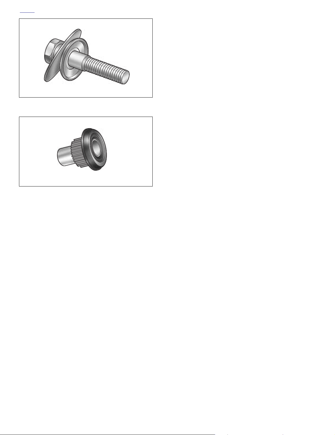
Frame
Boss
Air Inlet
Tube
Shock
Absorber
Compression
Fitting
Depress Collar on Fitting
and Pull Out Air Inlet Tube.
REAR SHOCK ABSORBERS 2.19
ADJUSTMENT
For the correct air pressure, see Section 2.18 REAR AIR
SUSPENSION.
REMOVAL
NOTE
If replacing both shock absorbers, remove and install one
shock at a time. Remove and install the second shock only
after the first shock is installed, but before the air suspension
system is pressurized.
1. Place the motorcycle on a hydraulic center stand with
the rear wheel raised off the ground.
2. Remove saddlebags. See Section 2.25 SADDLEBAG,
REMOVAL.
11WARNING1WARNING
Exercise caution when bleeding air from the air valve.
Moisture combined with lubricant (either from shock
assembly or drip oiler in the air compressor lines) may
be ejected onto the rear wheel, tire and/or brake components and adversely affect traction and/or braking efficiency, which could result in death or serious injury.
3. Remove protective cap from air valve. Using a no-loss
AIR SUSPENSION PUMP AND GAUGE (Part No. HD-
34633), add 3-5 psi (20.7-34.5 kPa) to purge lines of any
oil.
4. Depress pin in valve to bleed air from shocks.
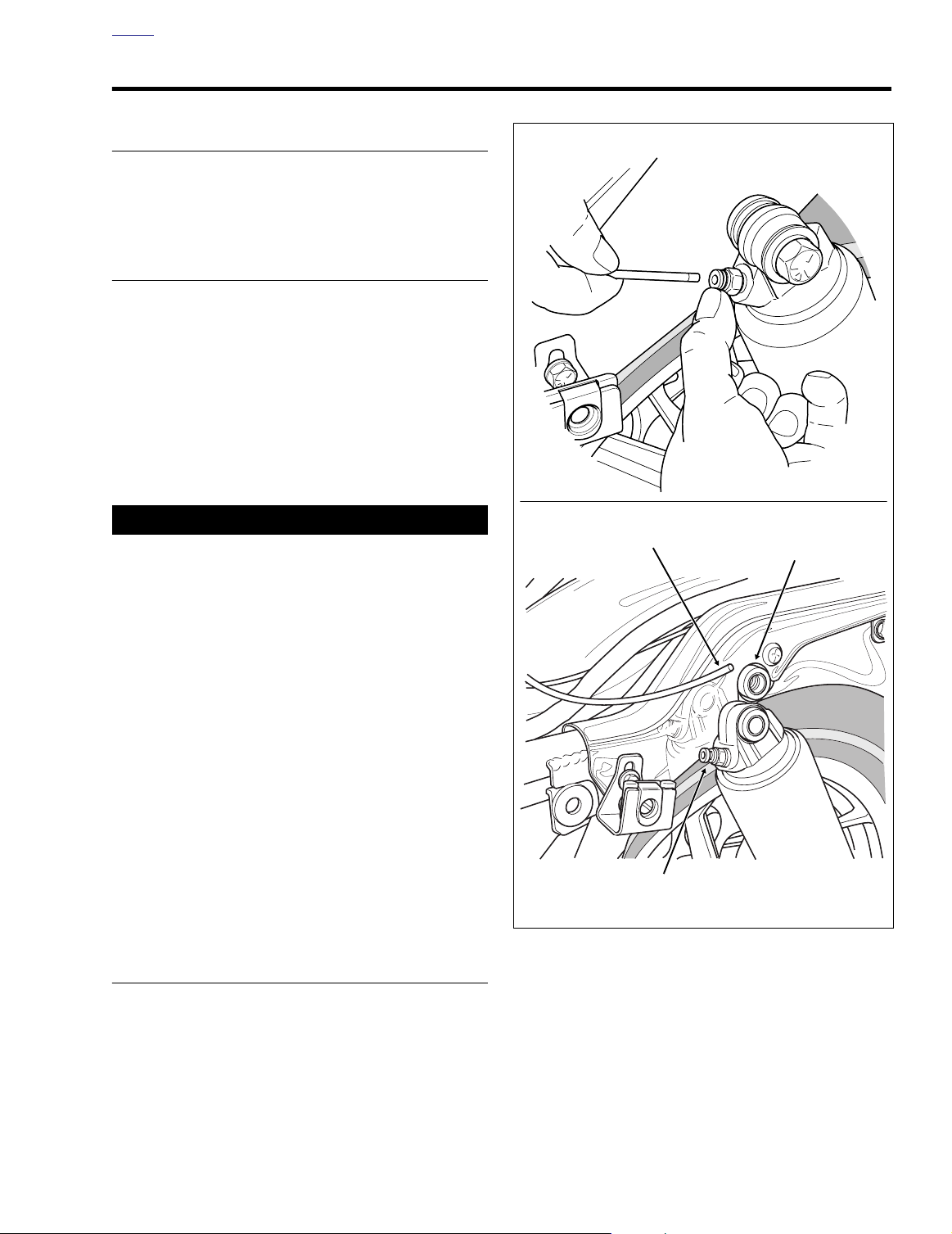
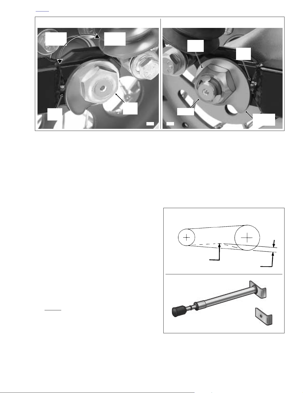
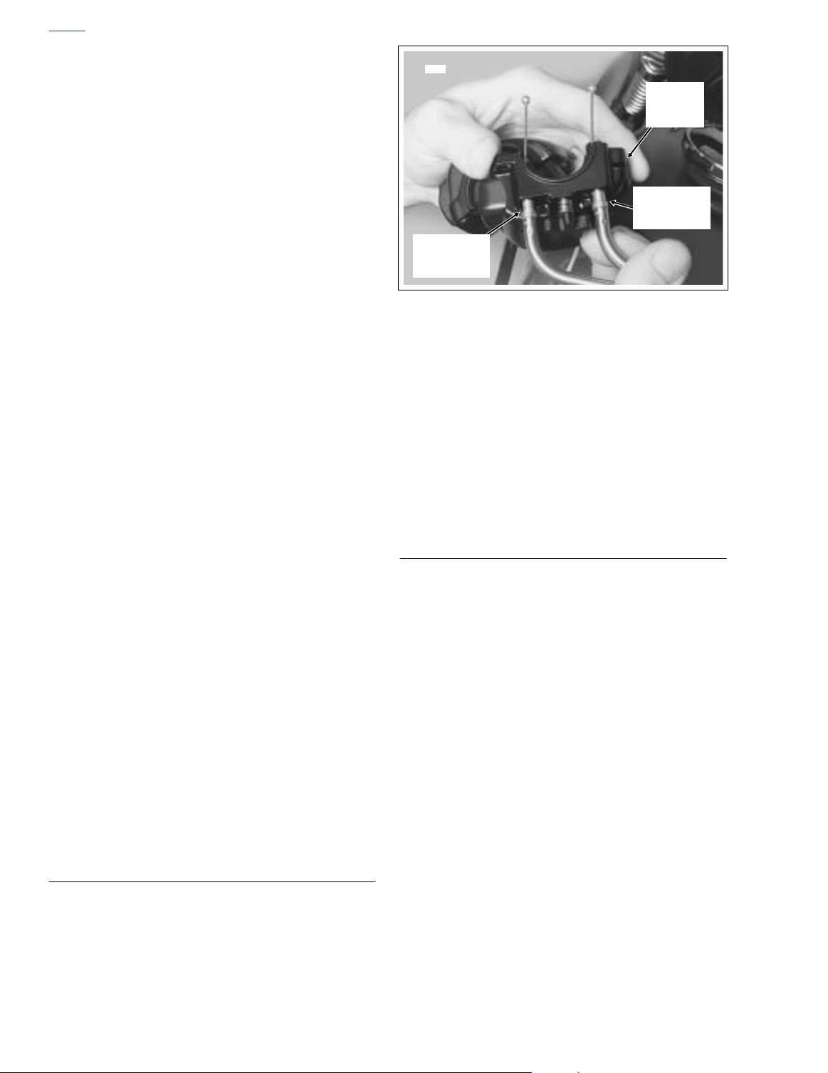
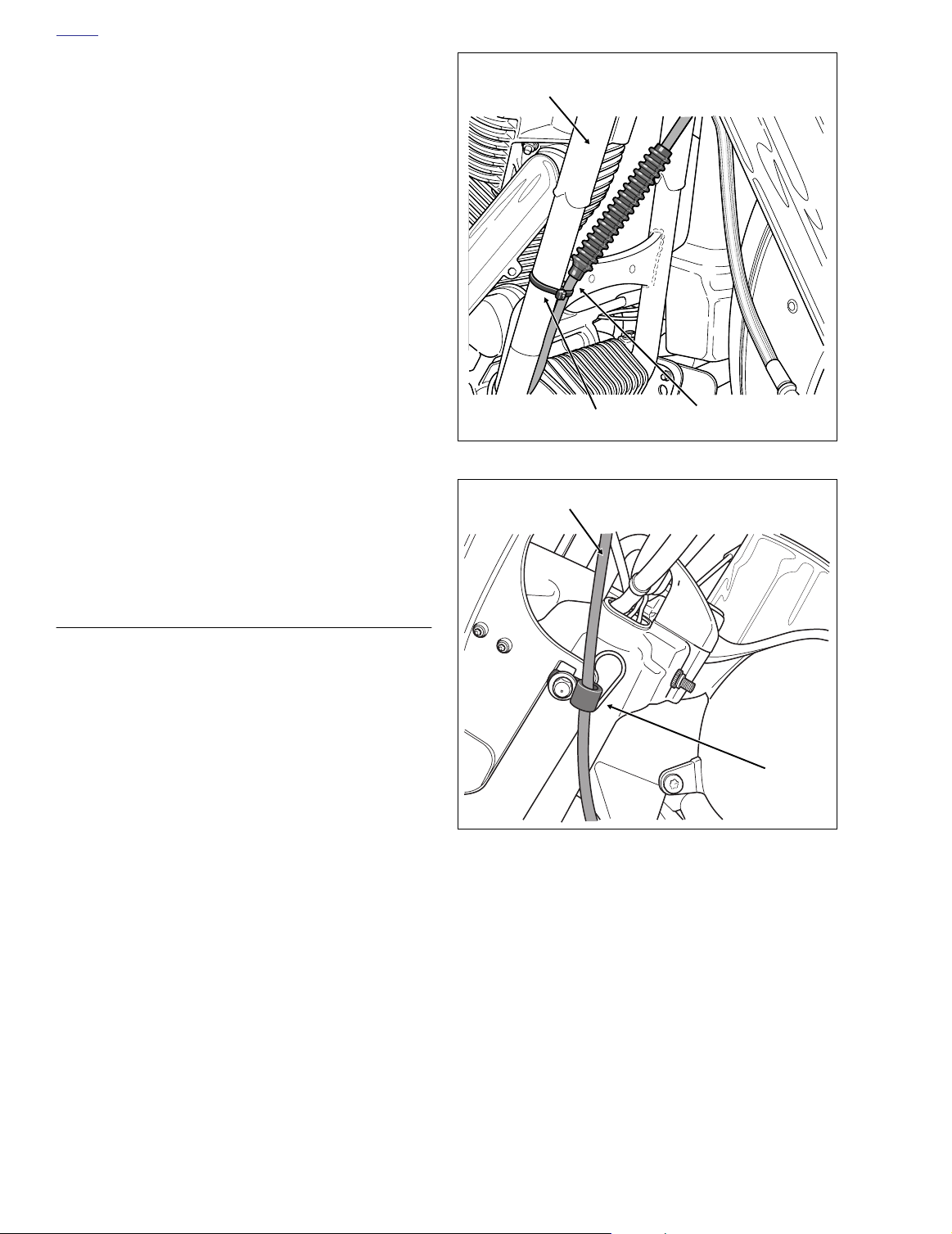
5. Depress collar on compression fitting to release air tube.
See upper frame of Figure 2-96.
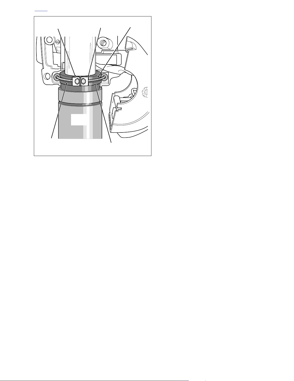
6. Remove the upper shock mounting bolt with lockwasher
and flat washer. See lower frame of Figure 2-96.
7. Remove the lower shock mounting bolt with lockwasher
and flat washer. Remove the shock absorber assembly
from the vehicle.
DISASSEMBLY
Figure 2-96. Remove Air Inlet Tube and
Upper Shock Mounting Bolt (Left Side View)
NOTE
Air shocks are not repairable. Replace the shocks if damaged or worn.
2004 Touring: Chassis 2-79
Page 2

HOME
CLEANING AND INSPECTION
1. Examine the rubber mounting bushings for cracks or
wear. Examine the shock for leaks. The unit should not
leak and should compress slightly easier than it extends.
Compare the action of the shock with a new one to judge
if it is worn. Replace the shock if necessary.
2. Clean and examine the shock mounting hardware.
Replace parts that are worn or damaged.
ASSEMBLY
NOTE
If the compression fittings were removed, apply PIPE SEALANT WITH TEFLON to the threads before assembly.
INSTALLATION
1. Install lockwasher and flat washer on the lower shock
mounting bolt. Insert bolt through the shock bottom
bushing.
2. Apply two or three drops of Loctite Medium Strength
Threadlocker 243 (blue) to threads.
3. Start bolt into rear swingarm mount. Tighten bolt to 3540 ft-lbs (47-54 Nm).
4. Install lockwasher and flat washer on the upper shock
mounting bolt. Insert bolt through the shock upper bushing
5. Apply two or three drops of Loctite Medium Strength
Threadlocker 243 (blue) to threads.
6. Start bolt into frame boss. Tighten bolt to 33-35 ft-lbs
(45-48 Nm).
7. Insert air tube into compression fitting until it bottoms.
Gently tug on tube to verify that it is locked in place.
NOTE
If replacing both shock absorbers, remove and install the
other shock at this time.
8. Pressurize rear air suspension system and check for
leaks. For the correct air pressure, see Section 2.18
REAR AIR SUSPENSION.
9. Install saddlebags. See Section 2.25 SADDLEBAG,
INSTALLATION.
2-80 2004 Touring: Chassis
Page 3
HOME
f2006x2x
Rear
Swingarm
Slot
Rubber
Mount
Pivot
Shaft
Locknut
REAR SWINGARM 2.20
REMOVAL
1. Remove saddlebags. See Section 2.25 SADDLEBAG,
REMOVAL.
2. Remove socket screw with lockwasher to remove passenger footboard from rear swingarm bracket. Repeat
step on opposite side of vehicle.
3. Remove both mufflers as follows:
Left Side
a. Open worm drive clamps to remove heat shield
from crossover pipe in front of muffler.
b. Using a bungee cord, tie the muffler to the lower
saddlebag support rail.
c. Loosen TORCA clamp between crossover pipe and
muffer.
d. Remove two bolts (with lockwashers) to detach muf-
fler from the lower saddlebag support rail.
e. Remove bungee cord to release muffler from lower
saddlebag support rail.
Right Side
a. Open worm drive clamps to remove heat shield
from rear header pipe in front of muffler.
b. Using a bungee cord, tie the muffler to the lower
saddlebag support rail.
c. Loosen TORCA clamp between rear header pipe
and muffer.
d. Remove two bolts (with lockwashers) to detach muf-
fler from the lower saddlebag support rail.
e. Remove bungee cord to release muffler from lower
saddlebag support rail.
4. Place the motorcycle on a hydraulic center stand. Slide
a block of wood beneath the oil pan to support the
weight of the transmission once the pivot shaft is
removed.
5. Standing on right side of vehicle, remove E-clip from
groove at end of axle.
6. Remove cone nut and adjuster cam from axle.
7. Using a soft mallet, gently tap end of axle towards left
side to loosen. Catching external spacers on right and
left side of hub, pull axle free of wheel and rear
swingarm.
8. Pull wheel to release brake disc from caliper. Pry inner
and outer brake pads back for additional clearance, if
necessary. Use a putty knife with a wide thin blade to
avoid scoring or scratching the brake disc.
Figure 2-97. Remove Rear Swingarm Bracket
(Left Side View)
9. Remove caliper from anchor weldment on rear swingarm, and carefully hang over lower saddlebag support
rail.
10. Roll wheel forward and slip belt off sprocket. Move wheel
out from beneath rear fender.
11. Remove belt guard from bottom of left side swingarm.
First remove two rear screws, and then loosen front
screw. Push belt guard toward the front of the vehicle
until screw engages large end of slot, and then remove.
12. Remove lower shock mounting bolt (with lockwasher and
flat washer) to release shock absorber from rear swingarm mount. Repeat step on opposite side of vehicle.
13. Remove two bolts (with lockwashers) to free rear swingarm bracket from left side of vehicle frame. See Figure 2-
97.
14. Moving to right side of vehicle, leave rear swingarm
bracket installed, but remove decorative chrome plug.
15. Open two cable clips on T-studs at top of right side swingarm. Free rear brake line hose from cable clips.
NOTE
For best results, insert blade of small screwdriver into gap at
side of clip and gently rotate end of screwdriver to pop open.
2004 Touring: Chassis 2-81
Page 4
HOME
Ram
Socket
Extension
Socket
Figure 2-98. Press Out Drive Side Bearing
16. Holding left side nut within rubber mount, remove right
side locknut from end of pivot shaft. Remove cup
washer.
17. Using a suitable drift, tap pivot shaft toward left side of
vehicle.
18. Moving to left side, pull pivot shaft assembly (pivot shaft,
locknut, cup washer, rubber mount and outer spacer) out
of transmission mount and left side swingarm. See
Figure 2-102.
19. Standing at rear of vehicle, work rear swingarm free of
transmission mount and rear swingarm brackets.
20. Remove outer spacer from right side swingarm tube.
21. Remove rubber mount from behind right side swingarm
bracket.
Socket
f1903x2x
Anchor
Weldment
Wood
Block
f1967x2x
Spacer
Bearing
DISASSEMBLY/ASSEMBLY
Bearing Removal
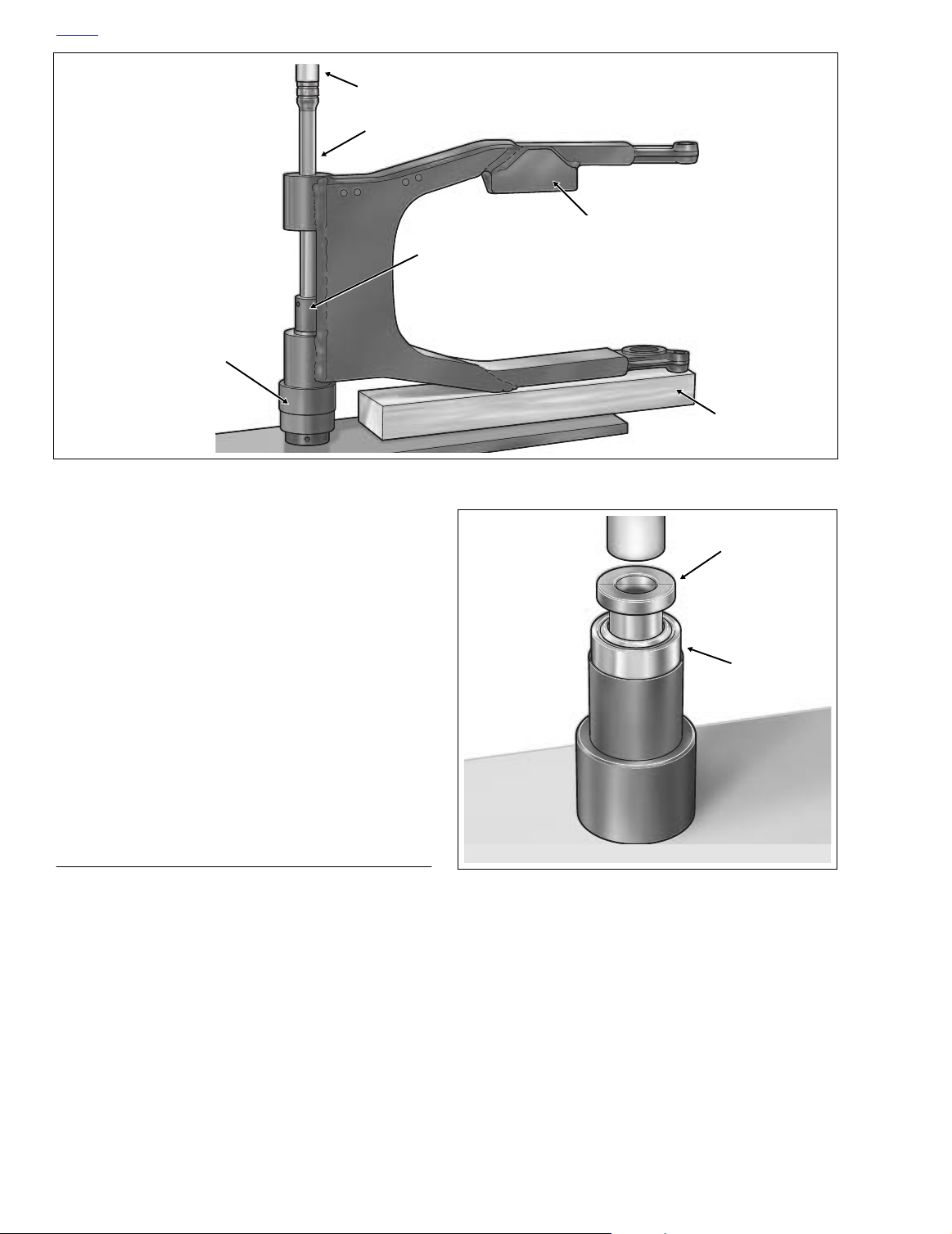
1. Move rear swingarm to an hydraulic press.
2. Place swingarm on its side, so that the brake side is on
top. The brake side is easily recognized by the anchor
weldment for mounting of the brake caliper.
3. Support the swingarm with a block of wood and a large
socket as shown in Figure 2-98. Ver ify that assembly is
square and the bearing bore is completely vertical.
2-82 2004 Touring: Chassis
Figure 2-99. Press Spacer Into Bearing
4. Slide driver handle (or long socket extension) through
the brake side swingarm tube and bearing until it contacts driver (or large socket) placed on inboard side of
drive side bearing.
5. Center driver handle (or long socket extension) under
ram and press drive side bearing from rear swingarm.
6. Remove tools from rear swingarm. Turn swingarm over
and repeat steps 3-5 to press out brake side bearing.
Page 5
HOME
f1914x2x
Pivot
Shaft
Rubber
Mount
Locknut and
Cup Washer
Spacer
Right Side
Drive Side
Driver
Figure 2-100. Rear Swingarm Bearing Installer (HD-
45327)
Brake Side
Driver
Brake Side
Driver
Anchor
Weldment
f1909x2x
a. Place swingarm on its side, so that the brake side is
on top. The brake side is easily recognized by the
anchor weldment for mounting of the brake caliper.
b. With the spacer inboard, insert bearing into out-
board side of brake side swingarm tube.
c. Insert driver stamped “Brake Side” into swingarm
tube until it contacts installed bearing. Center driver
under ram and press on brake side bearing until
shoulder on tool makes contact with casting of swingarm. See Figure 2-101.
d. Remove tool and turn rear swingarm over. With the
spacer inboard, insert bearing into outboard side of
drive side swingarm tube.
e. Insert driver stamped “Drive Side” into swingarm
tube until it contacts installed bearing. Center driver
under ram and press on drive side bearing until it
bottoms. Shoulder on tool will
with casting of swingarm.
f. Remove tool from swingarm. Remove swingarm
from hydraulic press.
not
mak
e contact
Pivot Shaft Disassembly
1. Partially install locknut on right side of pivot shaft. Install
second locknut on right side until it contacts the first.
Holding first locknut to prevent rotation of shaft, remove
left side locknut. See Figure 2-102.
2. Remove cup washer, rubber mount and outer spacer.
3. Remove right side locknuts from pivot shaft.
Bearing Installation
1. Obtain
2. Install assembled bearings into rear swingarm. Proceed
Figure 2-101. Press In Brake Side Bearing
new
rear swingarm bearings. Bearings and spacers must be assembled before installation. Proceed as
follows:
a. Obtain REAR SWINGARM BEARING INSTALLER
(HD-45327). See Figure 2-100.
b. With the nose topside, center one of the drivers
under ram of hydraulic press.
c. Place bearing over nose of driver. With the collar
topside, place spacer over nose and into bearing.
See Figure 2-99.
d. Apply pressure to spacer until it bottoms in bearing.
e. Repeat step to assemble second swingarm bearing.
as follows:
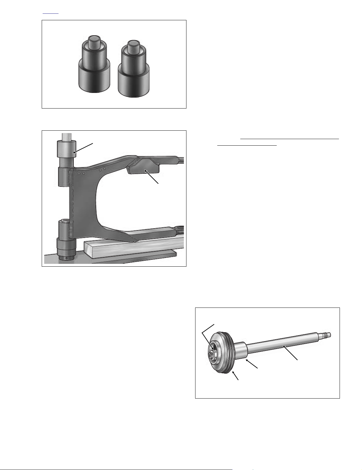
Pivot Shaft Assembly
1. With larger OD outboard, slide outer spacer onto left
side of pivot shaft until counterbore contacts shoulder on
shaft.
2. Install rubber mount with the flat side inboard toward
outer spacer.
3. Install cup washer with the concave side facing in toward
the rubber mount.
Figure 2-102. Pivot Shaft Assembly
2004 Touring: Chassis 2-83
Page 6

HOME
4. Apply two drops of Loctite Medium Strength Threadlocker 243 (blue) to threads of left side locknut, and then
start on shaft.
5. Partially install locknut on right side of pivot shaft. Install
second locknut on right side until it contacts the first.
Holding second locknut to prevent rotation of shaft,
tighten left side locknut to 40-45 ft-lbs (54-61 Nm).
6. Remove right side locknuts from pivot shaft.
INSTALLATION
1. With the slot on the outboard side between the twelve
and one o’clock positions, install rubber mount behind
rear swingarm bracket on right side of vehicle. Be sure
that index tab cast on inboard side of bracket fully
engages slot in rubber mount.
2. Place outer spacer into right side swingarm tube.
3. With the belt on the inboard side of the left side swingarm, work the rear swingarm into position between the
transmission mount and the rear swingarm brackets.
Use a rubber mallet and carefully tap swingarm into
position, if necessary.
4. The pivot shaft secures the rear swingarm and transmission to the vehicle frame. See Figure 2-102. Install the
pivot shaft as follows:
a. Coat pivot shaft with Loctite ANTI-SEIZE LUBRI-
CANT.
b. From left side of vehicle, slide pivot shaft assembly
(pivot shaft, locknut, cup washer, rubber mount and
outer spacer) through left side swingarm and transmission mount. After exiting right side swingarm,
guide end of pivot shaft through holes in rubber
mount and right side swingarm bracket.
c. With the concave side inboard, slide cup washer
onto end of pivot shaft.
d. Install locknut on pivot shaft. Holding left side nut on
pivot shaft, tighten locknut to 40-45 ft-lbs (54-61 Nm).
Now hold right side nut and tighten left side locknut
using the same torque value.
e. Carefully raise swingarm up and down slightly to
verify movement (and that assembly is not in a
bind).
f. Install decorative chrome plug in right side rear
swingarm bracket.
g. Moving to left side of vehicle, rotate the rubber
mount so that the slot is between the eleven and
twelve o’clock positions. Install left side swingarm
bracket fitting index tab into rubber mount slot. See
Figure 2-97.
h. Install two bolts (with lockwashers) to secure left
side swingarm bracket to vehicle frame. Tighten
bolts to 34-42 ft-lbs (46-57 Nm).
5. Install lockwasher and flat washer on the lower shock
mounting bolt. Insert bolt through the shock bottom
bushing. Apply two or three drops of Loctite Medium
Strength Threadlocker 243 (blue) to threads. Start bolt
into rear swingarm mount. Tighten bolt to 35-40 ft-lbs
(47-54 Nm). Repeat step on opposite side of vehicle.
6. Install belt guard at bottom of left side swingarm. Push
belt guard toward the rear of the vehicle until front screw
engages small end of slot. Install two rear screws, and
then tighten front screw.
7. Capture rear brake line hose in two cable clips at top of
right side swingarm. Snap cable clips closed.
8. Place wheel in rear swingarm. Slide wheel far enough
forward to slip belt over sprocket and then slide the
wheel back.
CAUTION
Do not bend or fold belt backward or into loops smaller
than 5 inches (127 mm) in diameter. Sharp bending can
weaken the belt and cause premature failure.
9. Seat caliper on anchor weldment of rear swingarm. Position wheel in swingarm, so that brake disc is centered
between brake pads.
10. Coat the axle with Loctite ANTI-SIEZE LUBRICANT.
11. With the larger OD on the outboard side, hold external
spacer between rear swingarm and belt sprocket. Slide
axle through left side of rear swingarm, external spacer,
and belt sprocket into wheel hub.
12. When axle emerges from hub on brake disc side of
wheel, push axle through
bracket and right side of rear swingarm.
13. Rotate axle so that the flat on the threaded end is topside. With the thumb down and the cam forward, install
adjuster cam on end of axle.
14. Apply a thin film of ANTI-SIEZE LUBRICANT to the
inboard side of the cone nut avoiding contact with
threads. Install cone nut on axle, but finger tighten only.
15. Verify that adjuster cam just contacts weld nub on both
sides of rear swingarm. If necessary, push wheel forward slightly to achieve the desired result. Snug the
cone nut to 15-20 ft-lbs (20-27 Nm). See Figure 2-103.
16. Check deflection at the loosest spot in the belt. Use
BELT TENSION GAUGE (HD-35381A), or install narro
saddle (HD-35381-3) on existing gauge, and apply 10
lbs. (4.5 kg) of force at the midpoint of the bottom belt
strand. See Figure 2-104. Belt deflection should be as
follows:
shor
t
external spacer, caliper
Table 2-4. Belt Deflection in the Air
Orientation
Motorcycle Upright
With Rear Wheel in the Air
See Section 6.4 SECONDARY DRIVE BELT AND SPROCKETS
for belt deflection specification with motorcycle on jiffy stand.
NOTE
Inches Millimeters
3/16 - 1/4 4.8 - 6.4
w
2-84 2004 Touring: Chassis
Page 7
HOME
10 lbs. (4.5 kg)
of Force
f1652x6x
See Tabl e 2-4.
Transmission
Sprocket
Rear Wheel
Sprocket
Belt Tension Gauge Adapter
Part No. HD-35381-3
Belt Tension Gauge
Part No. HD-35381A
RIGHT SIDELEFT SIDE
Increase
Belt
Deflection
Reduce
Belt
Deflection
Weld
Weld
Nut
Nub
8398
Figure 2-103. Move Rear Wheel Forward Until Adjuster Cams Just Contact Weld Nubs
17. If belt is too tight, move to step 18 to increase belt
deflection. If belt is too loose, reduce belt deflection as
described below:
a. Rotate weld nut on left side of axle in a clockwise
direction.
b. Check belt deflection. Apply 10 lbs. (4.5 kg) of force
at the midpoint of the bottom belt strand. Belt
deflection should be within the range specified in
Ta ble 2-4.
c. If belt is still too loose, repeat steps 17(a) through
17(b). If belt is now too tight, move to step 18.
Cone
Nut
Weld
Nub
E-Clip
Adjuster
8407
Cam
20. Recheck belt deflection to verify that it is still within specification.
If the belt deflection is not within specification, loosen
cone nut and then snug to 15-20 ft-lbs (20-27 Nm)
before returning to step 17.
21. With the flat side out, install
new
E-clip in groove on right
side of axle.
22. Depress rear brake pedal several times to set brake
pads to proper operating position within caliper.
18. If belt is too tight, increase belt deflection as follows:
19.
If the axle moves during tightening of the cone nut, then the
the belt deflection procedure must be restarted.
a. Rotate weld nut on left side of axle in a counter-
clockwise direction.
b. Push wheel forward slightly so that adjuster cam
just contacts weld nub on both sides of rear swingarm. See Figure 2-103.
c. Check belt deflection. Apply 10 lbs. (4.5 kg) of force
at the midpoint of the bottom belt strand. Belt
deflection should be within the range specified in
Ta ble 2-4.
d. If belt is still too tight, repeat steps 18(a) through
18(c). If belt is now too loose, move to step 17.
Holding
weld nut on left side of axle, tighten cone nut on
right side to 95-105 ft-lbs (128.8-142.4 Nm).
NOTE
Figure 2-104. Check and Adjust Belt Deflection
2004 Touring: Chassis 2-85
Page 8
HOME
11WARNING1WARNING
After installation of caliper and BEFORE moving motorcycle, pump rear brake pedal until pistons push pads
against the brake disc. If fluid pressure is not pumped
up, the rear brake will not be available the first time it is
used, a situation that could result in death or serious
injury.
23. Install both mufflers as follows:
NOTE
TORCA muffler clamps have eliminated the need for silicone
or graphite tape during assembly. To ensure sealing integrity
of muffler clamps and prevent the possibility of leakage, Harley-Davidson recommends that TORCA clamp assemblies be
discarded and replaced each time they are removed.
Left Side
a. Slide
b. Using a bungee cord, tie muffler to lower saddlebag
c. Tighten the two bolts (with lockwashers) to fasten
new
TORCA clamp onto free end of crossover
pipe.
support rail. Install muffler on crossover pipe. Place
TORCA clamp into position between crossover pipe
and muffler.
the muffler to the lower saddlebag support rail.
Passenger
Footboard
Bracket
Chrome
Plug
Rear
Swingarm
Bracket
f1787x2x
CAUTION
Verify that the exhaust pipes do not contact the vehicle
frame or any mounted components. Contact will cancel
the effect of the rubber isolation mounts and transmit
vibration to the rider via the vehicle frame.
d. Verify that exhaust pipes are in alignment and do
not contact the vehicle frame or mounted components.
e. Tighten the TORCA clamp to 45-60 ft-lbs (61-81
Nm).
f. Open worm drive clamps and install heat shield on
crossover pipe. Position clamp so that screw is on
the outboard side in the most accessible position.
CAUTION
Verify that the heat shields do not contact the vehicle
frame or any mounted components. Contact will cancel
the effect of the rubber isolation mounts and transmit
vibration to the rider via the vehicle frame.
g. Remove bungee cord from muffler.
Right Side
a. Slide
new
TORCA clamp onto free end of rear
header pipe.
Locknut
Pivot
Shaft
L(eft) Side
Casting Stamp
f2073x2x
Figure 2-105. Remove Chrome Plugs and Check
Pivot Shaft Locknut Torque (Left Side View)
2-86 2004 Touring: Chassis
Page 9

HOME
b. Using a bungee cord, tie muffler to lower saddlebag
support rail. Install muffler on rear header pipe.
Place TORCA clamp into position between rear
header pipe and muffler.
c. Tighten the two bolts (with lockwashers) to fasten
the muffler to the lower saddlebag support rail.
CAUTION
Verify that the exhaust pipes do not contact the vehicle
frame or any mounted components. Contact will cancel
the effect of the rubber isolation mounts and transmit
vibration to the rider via the vehicle frame.
d. Verify that exhaust pipes are in alignment and do
not contact the vehicle frame or mounted components.
e. Tighten the TORCA clamp to 45-60 ft-lbs (61-81
Nm).
f. Open worm drive clamps and install heat shield on
rear header pipe. Position clamp so that screw is on
the outboard side in the most accessible position.
CAUTION
Verify that the heat shields do not contact the vehicle
frame or any mounted components. Contact will cancel
the effect of the rubber isolation mounts and transmit
vibration to the rider via the vehicle frame.
25. Install saddlebags. See Section 2.25 SADDLEBAG,
INSTALLATION.
NOTE
Remove the decorative chrome plugs in the rear swingarm
brackets and check the torque on the pivot shaft locknuts
every 10,000 miles (16,000 km). See Figure 2-105. Holding
right side nut on the pivot shaft, tighten left side locknut to 4045 ft-lbs (54-61 Nm). Then hold left side nut and tighten right
side locknut using the same torque value.
g. Remove bungee cord from muffler.
24. Install socket screw with lockwasher to fasten passenger
footboard to rear swingarm bracket. Tighten screw to 1518 ft-lbs (20-24 Nm). Repeat step on opposite side of
vehicle.
2004 Touring: Chassis 2-87
Page 10
HOME
THROTTLE CABLES (NON-CRUISE) 2.21
ADJUSTMENT
NOTE
For throttle and idle cable adjustment or replacement on
cruise equipped models, see Section 8.30 CRUISE CON-
TROL (FLHRC, FLTR, FLHTCU).
The throttle control must operate freely without binding. With
the tension adjuster screw backed off, the throttle control grip
must freely return to the closed (idle) position. The throttle
control also must open and close freely when the front wheel
is turned to both the right and left fork stops. If the throttle
grip does not return to the idle position freely, check the
adjuster screw tension. If the adjuster screw is backed off,
inspect the cables for short bends.
11WARNING1WARNING
Do not overtighten the tension adjuster screw. An overtightened screw will prevent the engine from automatically returning to idle in an emergency situation. This
can lead to loss of vehicle control, which could result in
death or serious injury.
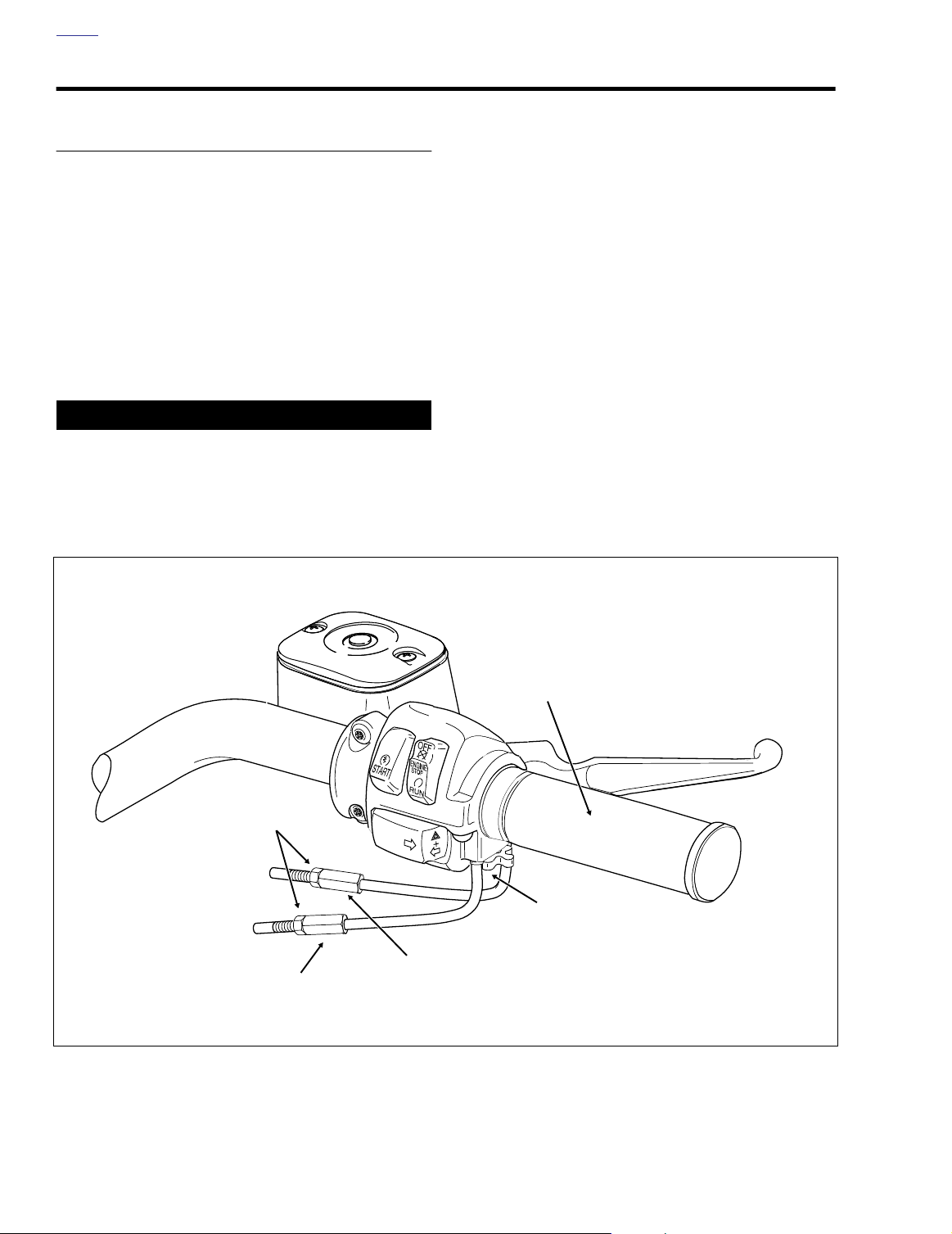
1. Slide rubber boot off throttle cable adjuster. See Figure
2-106. Holding cable adjuster with a 3/8 inch wrench,
loosen jam nut turning in a clockwise direction. Back jam
nut away from cable adjuster until it stops. Turn adjuster
clockwise until it contacts jam nut. Repeat procedure on
idle cable adjuster.
2. Point the front wheel straight ahead. Turn the throttle
control grip so that the throttle is wide open (fully counterclockwise) and then hold in position. Now turn the
throttle cable adjuster counter-clockwise until the throttle
cam stop just touches the stop plate. See Figure 2-107.
Release the throttle control grip and then tighten the jam
nut against the throttle cable adjuster. Cover cable
adjuster mechanism with rubber boot.
3. Turn the front wheel full right. Turn the idle cable adjuster
counterclockwise until the cable housing just touches
the spring in the cable guide (as seen through slot).
Work the throttle grip to verify that the throttle cable
returns to the idle position when released. If the cable
does not return to idle, turn the adjuster clockwise
slightly until the correct response is achieved. Tighten
jam nut against the idle cable adjuster and cover cable
adjuster mechanism with rubber boot.
Throttle Control
Grip
Jam Nut
Tension
Adjuster
Screw
Throttle Cable
Idle Cable
Adjuster
Figure 2-106. Throttle Cable Assembly - Throttle Side (FLHR)
Adjuster
f1376b2x
2-88 2004 Touring: Chassis
Page 11
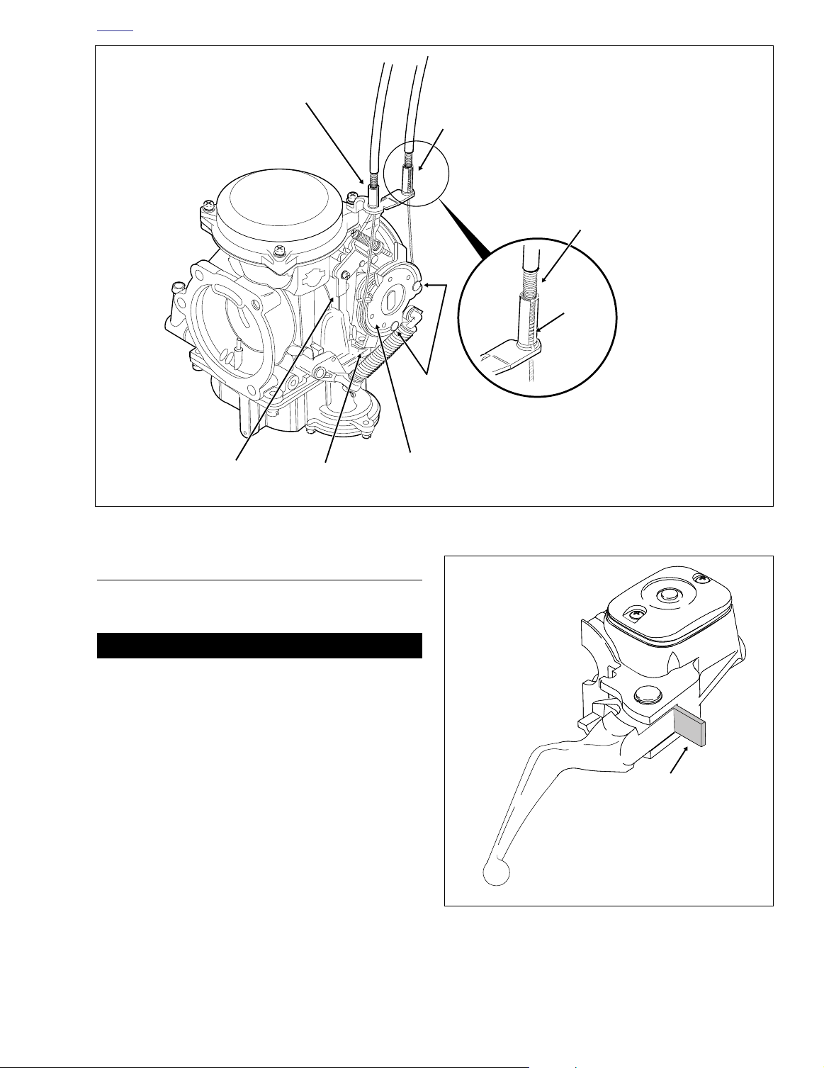
HOME
f1225x2x
5/32 Inch
(4.0 mm)
Cardboard
Insert
Throttle
Cable Guide
Idle
Cable Guide
Cable
Housing
Spring
Cable
Barrel End
Stop Plate
Throttle
Cam Stop
Figure 2-107. Throttle Cable Assembly - Carburetor Side
Throttle
Wheel
REMOVAL
THROTTLE SIDE
CAUTION
Do not remove the switch housing assembly without first
placing the 5/32 inch (4.0 mm) cardboard insert between
the brake lever and lever bracket. Removal without the
insert may result in damage to the rubber boot and
plunger of the Front Stoplight Switch.
NOTE
Use the eyelet of an ordinary cable strap if the cardboard
insert is not available.
1. Place the cardboard insert between the brake lever and
lever bracket. See Figure 2-108.
2. Using a T25 TORX drive head, remove the upper and
lower switch housing screws.
3. Using a T27 TORX drive head, loosen the upper screw
securing the handlebar clamp to the master cylinder
housing. Remove the lower clamp screw with flat
washer.
f1381a2x
Figure 2-108. Install Cardboard Insert
2004 Touring: Chassis 2-89
Page 12
HOME
4. Remove the brass ferrules from the notches on the
inboard side of the throttle control grip. Remove the ferrules from the cable end fittings.
5. Remove the friction shoe from the end of the tension
adjuster screw.
NOTE
The friction shoe is a loose fit and may fall out or become dislodged if the lower switch housing is turned upside down or
shaken.
6. Remove the throttle control grip from the end of the handlebar.
7. Pull the crimped inserts at the end of the throttle and idle
cable housings from the lower switch housing.
For best results, use a rocking motion while pulling.
Place a drop of light oil on the retaining rings, if necessary. Remove the cables from the switch housing.
CARBURETOR/INDUCTION MODULE SIDE
1. Remove the air cleaner and backplate. See Section 4.5
AIR CLEANER, REMOVAL.
2. Raise fuel tank to access cables in area of frame backbone. For carbureted models, see Section 4.7 FUEL
TANK (CARBURETED), PA RTIAL REMOVAL, FLHT/C,
or FLHR/S. For fuel injected models, see Section 9.4
FUEL TANK (FUEL INJECTED), PARTIAL REMOVAL,
FLHT/C/U/I, FLTRI, or FLHR/C/S/I.
3.
Carbureted:
idle cable barrel from upper inboard hole in throttle
wheel. Pull throttle cable barrel from remaining hole.
Release idle and throttle cables from guides in throttle
cable bracket. See Figure 2-107.
Induction Module:
pull idle cable barrel from upper hole in throttle wheel.
Pull throttle cable barrel from lower hole. Using slots,
release idle and throttle cables from guides in throttle
cable bracket. See Figure 2-111.
4. Free cables from J-clamp riveted to right side of frame
backbone.
5. If present, remove screw (with flat washer) to release Jclamp from wellnut in right side of steering head.
Remove J-clamp from cables.
Using a needle nose pliers, carefully pull
Using a needle nose pliers, carefully
7961
Lower
Switch
Housing
Throttle
Cable Insert
(Silver)
Idle
Cable Insert
(Gold)
Figure 2-109. Install Throttle/Idle Cables
in Lower Switch Housing
2. Inspect the cables for damage or wear. Replace the
cables if frayed, kinked or bent.
3. Obtain tube of Lubit-8 Tufoil Chain and Cable Lube (HD
Part No. 94968-85TV- 1/4 fl. oz.). Insert pin of tube
between throttle cable and cable housing. Squirt a few
drops of lubricant into cable housing moving pin around
cable OD. Repeat the procedure squirting a few drops
between the idle cable and cable housing.
INSTALLATION
THROTTLE SIDE
1. Apply a light coating of graphite to the handlebar and
inside surface of the switch housings.
2. Push the throttle and idle cables into the lower switch
housing until they snap in place. See Figure 2-109. Proceed as follows:
Note the different diameter inserts crimped into the end
of the throttle and idle cable housings.
Push the larger diameter insert (silver) on the throttle
cable housing into the larger hole in front of the tension
adjuster screw.
Push the smaller diameter insert (gold) on the idle cable
housing into the smaller hole at the rear of the tension
adjuster screw.
CLEANING AND INSPECTION
1. Clean all parts in a non-flammable cleaning solvent and
blow dry with compressed air.
2-90 2004 Touring: Chassis
NOTE
To aid assembly, place a drop of light oil on the retaining
rings of the crimped inserts. Always replace the retaining
rings if damaged or distorted.
Page 13
HOME
Ferrule
Throttle
Grip
8. Position the brake lever/master cylinder assembly
GrooveNotch
inboard of the switch housing assembly engaging the
tab on the lower switch housing in the groove at the top
of the brake lever bracket.
9. Align the holes in the handlebar clamp with those in the
master cylinder housing and start the lower screw (with
flat washer). Position for rider comfort. Beginning with
the top screw, tighten the screws to 60-80
Nm) torque using a T27 TORX drive head.
10. Using a T25 TORX drive head, tighten the lower and
upper switch housing screws to 35-45
NOTE
Always tighten the lower switch housing screw first so that
any gap between the upper and lower housings is at the front
of the switch assembly.
11. Remove the cardboard insert between the brake lever
and lever bracket.
in-lbs
in-lbs
(6.8-9.0
(4-5 Nm).
Idle
Cable
Figure 2-110. Install Throttle/Idle Control Cables on
Throttle Control Grip
3. With the concave side facing upward, install the friction
shoe so that the pin hole is over the point of the adjuster
screw.
NOTE
The friction shoe is a loose fit and may fall out or become dislodged if the lower switch housing is turned upside down or
shaken.
4. Slide the throttle control grip over the end of the right
handlebar until it bottoms against the closed end. Rotate
the grip so that the ferrule notches are at the top. To prevent binding, pull the grip back about 1/8 inch (3.2 mm).
5. Position the lower switch housing beneath the throttle
control grip. Install the brass ferrules onto the cables so
that the end fittings seat in the ferrule recess. Seat the
ferrules in their respective notches on the throttle control
grip. Verify that the cables are captured in the grooves
molded into the grip. See Figure 2-110.
6. Position the upper switch housing over the handlebar
and lower switch housing. Verify that the wire harness
conduit runs in the depression at the bottom of the handlebar.
7. Start the upper and lower switch housing screws, but do
not tighten.
Throttle
Cable
f1474x2x
12. Turn the Ignition/Light Key Switch to IGNITION and
apply brake lever to test operation of brake lamp.
CARBURETOR/INDUCTION MODULE SIDE
1. Route the throttle and idle cables as follows:
FLHT/C:
line to the inner fairing. Pass the cables through the
inner fairing grommet and then loop them toward the
rear along the right side of the steering head.
FLHR/C:
handlebar to the handlebar clamp shroud. Pass the
cables through the opening in the shroud and then loop
them toward the rear along the right side of the steering
head. Capture cables in J-clamp and then start screw
(with flat washer) to fasten J-clamp to wellnut in right
side of steering head. Tighten screw to 9-18
2.0 Nm).
2. Route the throttle and idle cables rearward along the
right side of the frame backbone. After passing through
J-clamp riveted to frame backbone, route cables downward to carburetor/induction module.
3.
Carbureted:
shorter cable guide in throttle cable bracket. Drawing
throttle cable downward, fit barrel end into lower outboard hole in throttle wheel. Install sleeve and spring on
idle cable housing into longer cable guide inserting barrel end into upper inboard hole in throttle wheel. See
Figure 2-107.
Route the cables downward following the brake
Route the cables downward following the right
in-lbs
(1.0-
Install sleeve on throttle cable housing into
2004 Touring: Chassis 2-91
Page 14
HOME
f2162x9x
Throttle Cable
Guide
Figure 2-111. Throttle Cable Assembly -
Induction Module Side
Induction Module:
ing into shorter cable guide at top of throttle cable
bracket. Drawing throttle cable downward, fit barrel end
into lower hole in throttle wheel. Install sleeve and spring
on idle cable housing into longer cable guide at bottom
of throttle cable bracket inserting barrel end into upper
hole in throttle wheel. See Figure 2-111.
4. Tighten cables as necessary to keep barrel ends from
dislodging. Verify that cables are seated in channel of
throttle wheel. Verify operation by turning throttle grip
and observing cable action. Adjust throttle cables as
described under ADJUSTMENT.
Install sleeve on throttle cable hous-
Idle Cable
Guide
LUBRICATION
1. See REMOVAL, THROTTLE SIDE, in this section, steps
1-5.
2. Move upper switch housing to the side in order to access
lower housing.
1CAUTION
Lubit-8 Tufoil Chain and Cable Lube contains detergents.
Keep out of reach of children. Contact with eyes may
result in minor or moderate injury.
3. Obtain tube of Lubit-8 Tufoil Chain and Cable Lube (HD
Part No. 94968-85TV- 1/4 fl. oz.). Insert pin of tube
between throttle cable and cable housing inside lower
switch housing. Squeeze tube to squirt a quantity of
lubricant into cable housing moving pin around cable
OD. See Figure 2-112.
4. Repeat the procedure squirting a quantity of lubricant
between the idle cable and cable housing.
5. See INSTALLATION, THROTTLE SIDE, in this section,
steps 3-12.
6. Turn the Ignition/Light Key Switch to IGNITION and
apply brake lever to test operation of brake lamp.
Insert
Lubricant
Here
5. Install fuel tank. For carbureted models, see Section 4.7
FUEL TANK (CARBURETED), INSTALLATION (AFTER
PA RTIAL REMOVAL), FLHT/C, or FLHR/S. For fuel
injected models, see Section 9.4 FUEL TANK (FUEL
INJECTED), INSTALLATION (AFTER PARTIAL
REMOVAL), FLHT/C/U/I, FLTRI, or FLHR/C/S/I.
6. Install the air cleaner assembly. See Section 4.5 AIR
CLEANER, INSTALLATION.
2-92 2004 Touring: Chassis
7958
Figure 2-112. Right Handlebar Lower Switch Housing
Page 15
HOME
11WARNING1WARNING
f1140axx
Flat
Washer
Retaining
Ring
Anchor
Pin
Handlebar
Clamp
Clutch
Lever
Bracket
Anti-Rattle
Spring
and Screw
Screw
Bushing
O-Ring
Rubber Boot
Pivot Pin
Hand Lever
Clutch Cable
f1896x7x
Inner
Ramp
Retaining
Ring
Cable
Fitting
Coupling
Clutch Cable
CLUTCH CABLE 2.22
ADJUSTMENT
See Section 6.3 CLUTCH, ADJUSTMENT.
REMOVAL
1. Remove maxi-fuse. See Section 8.3 SYSTEM FUSES,
MAXI-FUSE, REMOVAL.
2. To access the clutch release cover assembly, remove
right side exhaust system. See Section 3.7 REMOVING
ENGINE FROM CHASSIS, steps 3-9.
3. Remove the magnetic drain plug at the bottom right side
of the oil pan and drain the transmission lubricant into a
suitable container. Remove the filler plug/dipstick.
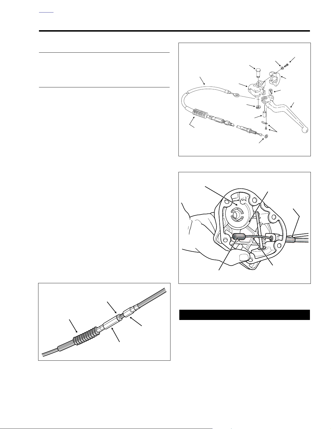
4. Slide rubber boot off clutch cable adjuster. Holding cable
adjuster with 1/2 inch wrench, loosen jam nut using 9/16
inch wrench. Back jam nut away from cable adjuster.
Move adjuster toward jam nut to introduce free play at
hand lever. See Figure 2-113.
5. Remove retaining ring from pivot pin groove at bottom of
clutch lever bracket. Remove pivot pin.
6. Remove clutch hand lever from clutch lever bracket. If
necessary, use a T27 TORX drive head and remove two
screws (with flat washers) to release handelbar clamp
from clutch lever bracket.
7. Remove anchor pin and clutch cable eyelet from clutch
hand lever. See Figure 2-114.
8. Remove six socket head screws and washers to free
clutch release cover from transmission case. Remove
and discard gasket. See Figure 2-115.
f1440x6x
Jam
Nut
Rubber
Boot
Figure 2-114. Clutch Hand Lever Assembly
Figure 2-115. Clutch Release Cover Assembly
Figure 2-113. Clutch Cable Adjuster Mechanism
Cable
Adjuster
Cable
End
Always wear proper eye protection when removing retaining rings. Use the correct retaining ring pliers. Verify
that the tips of the pliers are not damaged or excessively
worn. Slippage may propel the ring with enough force to
cause eye injury.
9. Remove retaining ring securing ball and ramp mechanism to clutch release cover.
2004 Touring: Chassis 2-93
Page 16
HOME
10. Lift inner ramp out of clutch release cover and turn the
assembly over so that ball sockets are facing outboard.
Remove hook of ramp from button on coupling. Remove
coupling from clutch cable end.
11. Remove balls from outer ramp sockets. Remove outer
ramp from clutch release cover.
12. Unscrew the cable fitting from the clutch release cover.
Remove clutch cable and fitting.
13. Cut cable strap in hole of crossbrace to free clutch cable
from right frame downtube. See Figure 2-116. Continue
as follows:
FLHR/C/S:
Remove T40 TORX screw with flat washer
(FLHRS) or acorn nut (FLHR/C) to release clutch cable
from P-clamp fastened to upper fork bracket. See Figure
2-117.
FLTR:
Release clutch cable from cable clip anchored in
hole on left side of instrument nacelle.
FLHT/C/U:
Remove the outer fairing. See Section 2.29
UPPER FAIRING/WINDSHIELD (FLHT/C/U), OUTER
FAIRING/WINDSHIELD, REMOVAL. Cut cable strap to
release clutch cable from left fairing bracket. See Figure
2-118.
14. Remove clutch cable from motorcycle.
NOTE
If ball and ramp or throwout bearing and clutch pushrod need
service, see Section 7.5 CLUTCH RELEASE COVER.
Right Frame
Downtube
Cable Strap
Clutch Cable
f1472b2x
Figure 2-116. Clutch Cable Routing (Right Side View)
Clutch Cable
f2257x2x
INSTALLATION
1. See Figure 2-114. Insert clutch cable eyelet into groove
of clutch hand lever aligning eyelet with hole without
bushing. Insert anchor pin through lever and eyelet.
2. Insert lever into groove of clutch lever bracket fitting
sleeve at end of cable housing into bore on inboard side
of bracket.
3. Align hole in hand lever with hole in bracket and install
pivot pin. Install retaining ring in pivot pin groove.
4. If removed, use a T27 TORX drive head and install two
screws (with flat washers) to secure handelbar clamp to
clutch lever bracket. See Figure 2-114. Starting with the
top screw, tighten screws to 60-80
5. Start clutch cable routing as follows:
FLHR/C/S:
Capture clutch cable in P-clamp and fasten
to upper fork bracket using T40 TORX screw with flat
washer (FLHRS) or acorn nut (FLHR/C). Orient P-clamp
as shown in Figure 2-117. On left side of steering head,
run cable downward between engine guard and front of
left frame downtube.
FLTR:
Capture clutch cable in cable clip and anchor clip
in hole on left side of instrument nacelle. Run cable forward and then rearward beneath instrument nacelle following left side of steering head. Run cable downward
between engine guard and front of left frame downtube.
in-lbs
(6.8-9.0 Nm).
Clamp
Figure 2-117. Clutch Cable Routing - FLHR/C
(Left Side View)
FLHT/C/U:
Feed clutch cable through grommet on left
side of inner fairing. Route cable on inboard side of left
fairing bracket between upper and lower wings of radio
(or storage box) support bracket. Cable strap clutch
cable to left fairing bracket using oblong hole at this location. See Figure 2-118. Run cable downward along left
side of steering head, and then between engine guard
and front of left frame downtube. Install the outer fairing.
See Section 2.29 UPPER FAIRING/WINDSHIELD
(FLHT/C/U), OUTER FAIRING/WINDSHIELD, INSTALLATION.
2-94 2004 Touring: Chassis
Page 17
HOME
CAUTION
8496
Clutch
Release
Cover
Filler
Plug
OMF50
O-Ring
9421
Cable
Strap
12. Install the retaining ring so that the opening is to the right
of the outer ramp tang slot in the clutch release cover.
13. Verify that the two locating dowels are in place on the
right side of the transmission case. Hang a
new
gasket
on the dowels.
14. Holding the clutch release cover in position, install six
socket head screws. Tighten screws to 120-144
in-lbs
(13.6-16.3 Nm).
15. Tighten clutch cable fitting to 36-60
in-lbs
(4-7 Nm).
16.Check the O-ring on the transmission drain plug for
tears, cuts or general deterioration. Replace as necessary.
Figure 2-118. Secure Clutch Cable to Fairing Bracket
6. Complete clutch cable routing as follows:
All Models:
Continue downward progression while
crossing to right side of motorcycle and then run cable
between outboard side of voltage regulator and inboard
side of right frame downtube. Threading cable strap
through hole in crossbrace, secure clutch cable to downtube as shown in Figure 2-116. Following inboard side of
frame downtube, route cable between bottom of cam
cover and top of lower frame tube to area of clutch
release cover.
7. Inspect cable fitting O-ring and replace if damaged or
deformed. Install clutch cable fitting into clutch release
cover. See Figure 2-115. Do not tighten cable fitting at
this time.
8. Place outer ramp in clutch release cover recess with
tang in cover slot.
9. Apply a multi-purpose grease to the balls and outer
ramp sockets. Place a ball in each of three outer ramp
sockets.
10. Hold coupling with button facing outboard. Place cable
end in recess of coupling. With ball sockets facing outboard, place hook of inner ramp on button of couplng.
Holding inner ramp and coupling together, turn the
assembly over.
11. Place inner ramp (ball socket side down) over balls in
outer ramp sockets.
Do not overtighten filler plugs or drain plugs. Overtightening plugs can cause leaks.
17.Install transmission the drain plug. Tighten the plug to
14-21 ft-lbs (19-28 Nm).
Figure 2-119. Transmission Case (Right Side)
11WARNING1WARNING
Always wear proper eye protection when installing retaining rings. Use the correct retaining ring pliers. Verify
that the tips of the pliers are not damaged or excessively
worn. Slippage may propel the ring with enough force to
cause eye injury.
Figure 2-120. Transmission Lubricant Filler Plug/Dipstick
2004 Touring: Chassis 2-95
Page 18

HOME
18. Remove the filler plug from the clutch release cover, if
installed. See Figure 2-119. Check the O-ring for tears,
cuts or general deterioration. Replace as necessary.
See Figure 2-120.
19. Fill the transmission with 20-24 oz. (590-710 ml) of
transmission lubricant or until the lubricant level on the
dipstick of the filler plug is at the F(ULL) mark with the
motorcycle in a level, upright position and the filler plug
resting on the threads. Use only Harley-Davidson
TRANSMISSION LUBRICANT, Part No. 99892-84
(quart) or Part No. 99891-84 (gallon).
20. Install the transmission filler plug/dipstick in the clutch
release cover. Tighten the plug to 25-75
in-lbs
(2.8-8.5
Nm).
21. Adjust the clutch cable. See Section 6.3 CLUTCH,
ADJUSTMENT.
22. Install right side exhaust system. See Section 3.8
INSTALLING ENGINE IN CHASSIS, steps 46-52.
23. Install maxi-fuse. See Section 8.3 SYSTEM FUSES,
MAXI-FUSE, INSTALLATION.
2-96 2004 Touring: Chassis
Page 19

HOME
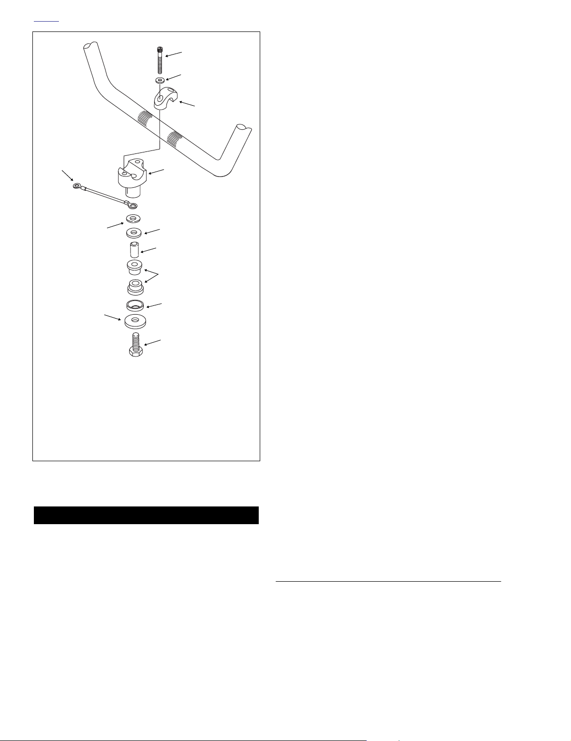
HANDLEBARS 2.23
HANDLEBAR ADJUSTMENT
1. Remove maxi-fuse. See Section 8.3 SYSTEM FUSES,
MAXI-FUSE, REMOVAL.
2.
FLHR/C/S:
Section 2.31 WINDSHIELD/HEADLAMP NACELLE
(FLHR/C/S), NACELLE REMOVAL (FLHR/C), steps 1-
11, or NACELLE REMOVAL (FLHRS), steps 1-7.
FLTR:
UPPER FAIRING/WINDSHIELD (FLTR), BEZEL,
REMOVAL.
FLHT/C/U:
UPPER FAIRING/WINDSHIELD (FLHT/C/U), FAIRING
CAP, REMOVAL.
3. Loosen rear screws on the upper handlebar clamps. On
FLTR models, loosen the front screws instead.
4. Position handlebars for rider posture and comfort.
5. To be sure that the handlebars are centered, verify that
the knurled area on the outboard side of the left side
handlebar clamp is equal to that on the right side.
6. Snug upper handlebar clamp screws.
Remove the handlebar clamp shroud. See
Remove the instrument bezel. See Section 2.30
Remove the fairing cap. See Section 2.29
11WARNING1WARNING
Improperly aligned handlebars can contact the fuel tank
when turned to the left or right fork stops. Contact with
the fuel tank while riding can cause loss of vehicle control resulting in death or serious injury.
7. Slowly turn handlebars to the full right fork stop and then
the full left fork stop to be sure there is no contact with
the fuel tank. If contact occurs and handlebars are properly aligned, raise handlebars as necessary until the
proper clearance is obtained.
8. Tighten the upper handlebar clamp screws to 12-16 ftlbs (16.3-21.7 Nm).
9.
FLHR/C/S:
Section 2.31 WINDSHIELD/HEADLAMP NACELLE
(FLHR/C/S), NACELLE INSTALLATION (FLHR/C),
steps 3-15, or NACELLE INSTALLATION (FLHRS),
steps 5-13.
FLTR:
UPPER FAIRING/WINDSHIELD (FLTR), BEZEL,
INSTALLATION.
FLHT/C/U:
UPPER FAIRING/WINDSHIELD (FLHT/C/U), FAIRING
CAP, INSTALLATION.
Install the handlebar clamp shroud. See
Install the instrument bezel. See Section 2.30
Install the fairing cap. See Section 2.29
10. If necessary, adjust left and right handlebar switch controls as follows:
a. Using a T27 TORX drive head, loosen the two
screws securing the handlebar clamp to the clutch
lever bracket (left) or master cylinder housing
(right).
b. Position switch controls for rider posture and com-
fort.
c. Beginning with the top screw, tighten the screws to
60-80
in-lbs
(6.8-9.0 Nm).
11. Install maxi-fuse. See Section 8.3 SYSTEM FUSES,
MAXI-FUSE, INSTALLATION.
HANDLEBAR REMOVAL
1. Remove maxi-fuse. See Section 8.3 SYSTEM FUSES,
MAXI-FUSE, REMOVAL.
2. Place blanket or protective cover over front of fuel tank to
protect against scratches or other damage.
3.
FLHR/C/S:
Section 2.31 WINDSHIELD/HEADLAMP NACELLE
(FLHR/C/S), NACELLE REMOVAL (FLHR/C), steps 1-
11, or NACELLE REMOVAL (FLHRS), steps 1-7.
FLTR:
UPPER FAIRING/WINDSHIELD (FLTR), INSTRUMENT
NACELLE, REMOVAL.
FLHT/C/U:
UPPER FAIRING/WINDSHIELD (FLHT/C/U), FAIRING
CAP, REMOVAL. Remove the radio (or storage box).
See Section 8.31 PREMIUM SOUND SYSTEM (FLHTC/
U, FLTR), RADIO (FLHTC/U), REMOVAL, steps 3-7.
4. Remove the left and right handlebar switch controls. See
Section 8.21 HANDLEBAR SWITCHES, REMOVAL.
5. Remove upper handlebar clamp screws (with flat washers). Remove upper handlebar clamps and handlebar.
Remove the handlebar clamp shroud. See
Remove the instrument nacelle. See Section 2.30
Remove the fairing cap. See Section 2.29
HANDLEBAR INSTALLATION
1. Place
2. To be sure that the handlebars are centered, verify that
3. Snug upper handlebar clamp screws.
new
handlebars on lower handlebar clamps.
Install upper handlebar clamps and loosely install clamp
screws (with flat washers).
the knurled area on the outboard side of the left side
handlebar clamp is equal to that on the right side.
2004 Touring: Chassis 2-97
Page 20
HOME
f2056x2x
1
2
3
*9
**10
4
5
6
7
5
**11
8
1. Screw
2. Flat washer
3. Upper clamp
4. Lower clamp
5. Cup washer
6. Spacer
7. Rubber bushing
8. Bolt
Figure 2-121. Handlebar Clamp Assemblies
*LEFT CLAMP ONLY
9. Ground cable
**RIGHT CLAMP ONLY
10. Flat washer
11. Large flat washer
11WARNING1WARNING
Improperly aligned handlebars can contact the fuel tank
when turned to the left or right fork stops. Contact with
the fuel tank while riding can cause loss of vehicle control resulting in death or serious injury.
5. Tighten upper handlebar clamp screws as follows:
a. Tighten front screws until upper and lower handle-
bar clamps make contact.
b. Tighten rear screws to 12-16 ft-lbs (16.3-21.7 Nm).
c. Tighten front screws to 12-16 ft-lbs (16.3-21.7 Nm).
NOTE
A slight gap will exist between the upper and lower clamps at
the rear of the handlebars after tightening.
6. Install the left hand grip. See LEFT HAND GRIP,
INSTALLATION, in this section.
7. Install the left and right handlebar switch controls. See
Section 8.21 HANDLEBAR SWITCHES, INSTALLA-
TION.
8.
FLHR/C/S:
Section 2.31 WINDSHIELD/HEADLAMP NACELLE
(FLHR/C/S), NACELLE INSTALLATION (FLHR/C),
steps 3-15, or NACELLE INSTALLATION (FLHRS),
steps 5-13.
FLTR:
UPPER FAIRING/WINDSHIELD (FLTR), INSTRUMENT
NACELLE, INSTALLATION.
FLHT/C/U:
UPPER FAIRING/WINDSHIELD (FLHT/C/U), FAIRING
CAP, INSTALLATION. Install the radio (or storage box).
See Section 8.31 PREMIUM SOUND SYSTEM (FLHTC/
U, FLTR), RADIO (FLHTC/U), INSTALLATION, steps 1-
6.
9. Install maxi-fuse. See Section 8.3 SYSTEM FUSES,
MAXI-FUSE, INSTALLATION.
10. Turn the ignition/light key switch to IGNITION and test
each handlebar switch for proper operation.
11. Apply front brake hand lever to test operation of brake
lamp.
12. Adjust idle and throttle control cables as follows:
Non-Cruise:
(NON-CRUISE), ADJUSTMENT.
Cruise Equipped:
TROL (FLHRC, FLTR, FLHTCU), CABLE ADJUSTMENT.
Install the handlebar clamp shroud. See
Install the instrument nacelle. See Section 2.30
Install the fairing cap. See Section 2.29
See Section 2.21 THROTTLE CABLES
See Section 8.30 CRUISE CON-
LEFT HAND GRIP
4. Slowly turn handlebars to the full right fork stop and then
the full left fork stop to be sure there is no contact with
the fuel tank. If contact occurs and handlebars are properly aligned, raise handlebars as necessary until the
proper clearance is obtained.
2-98 2004 Touring: Chassis
REMOVAL
1. Remove the left handlebar switch controls. See Section
8.21 HANDLEBAR SWITCHES, REMOVAL.
Page 21
HOME
f2077x2x
f2076x2x
2. Use a sharp blade to carefully cut rubber and then peel
off handlebar.
3. Thoroughly clean handlebar to remove all residual adhesive.
INSTALLATION
11WARNING1WARNING
HARLEY-DAVIDSON ADHESIVE contains METHYL
ETHYL KETONE, a chemical known to the State of California to cause cancer or other reproductive harm.
11WARNING1WARNING
Use HARLEY-DAVIDSON ADHESIVE in well ventilated
areas only. Vapors are flammable and can be harmful to
breath. Avoid contact with eyes, mucous membranes, or
prolonged contact with skin. Keep out of reach of children.
1. Obtain a
ADHESIVE (Part No. 99839-95). Apply a coat of the
adhesive to the inside surface of the grip one inch (25.4
mm) from the open end. Apply a coat to the end of the
handlebar.
2. Immediately push grip completely onto end of handlebar
using a twisting motion. Do not hesitate when installing
grip or adhesive may dry before installation is complete.
If the left hand grip is patterned, align it with the pattern on
the right grip with the throttle in the fully closed position.
3. Let 6-8 hours elapse (at 70
cure.
4. Install the left handlebar switch controls. See Section
8.21 HANDLEBAR SWITCHES, INSTALLATION.
new
left hand grip and HARLEY-DAVIDSON
NOTE
°
F.) to allow adhesive to fully
Right Side
3. Holding lower handlebar clamp to prevent rotation, turn
bolt at bottom of upper fork bracket until free.
4. Remove lower handlebar clamp, flat washer and cup
washer at top of upper fork bracket. See Figure 2-122.
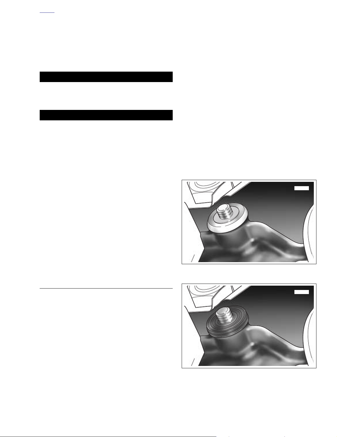
5. Pull bushing from fork bracket bore and discard. See
Figure 2-123.
6. Moving to bottom of upper fork bracket, remove bolt,
large flat washer and cup washer. See Figure 2-124.
7. Pull bushing and spacer from fork bracket bore. Remove
spacer from bushing. See Figure 2-125. Discard bushing.
Left Side
8. Holding lower handlebar clamp to prevent rotation, turn
bolt at bottom of upper fork bracket until free.
9. Remove lower handlebar clamp, ground wire ring terminal and cup washer at top of upper fork bracket.
RUBBER MOUNTS
NOTE
For complete disassembly of the handlebar clamp assemblies and/or to replace the rubber mounts, proceed as follows.
REMOVAL
General
1. Turn fork to left fork stop and loosen right side bolt at
bottom of upper fork bracket. Turn fork to right fork stop
and loosen left side bolt at bottom of upper fork bracket.
2. Remove handlebars. See HANDLEBAR REMOVAL in
this section.
Figure 2-122. Remove Flat Washer and
Upper Cup Washer (Right Side)
Figure 2-123. Remove Upper Bushing (Right Side)
2004 Touring: Chassis 2-99
Page 22
HOME
f2058x2x
Figure 2-124. Remove Bolt, Large Washer
and Lower Cup Washer (Right Side)
f2057x2x
Figure 2-125. Remove Spacer From Lower Bushing
5. Install cup washer over threaded end of bolt fitting concave side over collar of bushing. Install flat washer. See
Figure 2-122.
6. Apply two or three drops of Loctite Medium Strength
Threadlocker 243 (blue) to threads of bolt and start lower
handlebar clamp. Holding clamp to prevent rotation, turn
bolt at bottom of upper fork bracket until snug.
Left Side
7. Insert spacer into new bushing until flush with outboard
side of collar. See Figure 2-125.
8. Insert bushing into bore at bottom of upper fork bracket
fitting collar of bushing over lip of boss.
9. Install cup washer on bolt. Insert bolt into bushing fitting
concave side of cup washer over collar of bushing.
10. Moving to top of upper fork bracket, insert bushing into
bore fitting collar of bushing over lip of boss. See Figure
2-123.
11. Install cup washer over threaded end of bolt fitting concave side over collar of bushing. Install ground wire ring
terminal.
12. Apply two or three drops of Loctite Medium Strength
Threadlocker 243 (blue) to threads of bolt and start lower
handlebar clamp. Holding clamp to prevent rotation, turn
bolt at bottom of upper fork bracket until snug.
10. Pull bushing from fork bracket bore and discard. See
Figure 2-123.
11. Moving to bottom of upper fork bracket, remove bolt and
cup washer.
12. Pull bushing and spacer from fork bracket bore. Remove
spacer from bushing. See Figure 2-125. Discard bushing.
INSTALLATION
Right Side
1. Insert spacer into new bushing until flush with outboard
side of collar. See Figure 2-125.
2. Insert bushing into bore at bottom of upper fork bracket
fitting collar of bushing over lip of boss.
3. Install large flat washer and cup washer on bolt. See Fig-
ure 2-124. Insert bolt into bushing fitting concave side of
cup washer over collar of bushing.
4. Moving to top of upper fork bracket, insert bushing into
bore fitting collar of bushing over lip of boss. See Figure
2-123.
General
13. Install handlebars and upper handlebar clamps. See
HANDLEBAR INSTALLATION in this section, steps 1-5.
14. Turn fork to left fork stop and tighten right side bolt at
bottom of upper fork bracket to 30-40 ft-lbs (40.7-54.2
Nm). Turn fork to right fork stop and tighten left side bolt
to the same torque value.
15. Complete assembly of motorcycle. See HANDLEBAR
INSTALLATION in this section, steps 7-12.
2-100 2004 Touring: Chassis
Page 23
HOME
f1416x2x
f2171x2x
Tongue
Slot
Seat
Bottom
Frame
Backbone
SEAT 2.24
FLHR
REMOVAL
1. Remove Phillips screw to detach passenger seat mounting bracket from top of rear fender. See Figure 2-126.
Slightly lift up back of passenger seat and carefully slide
toward rear of vehicle to detach from front seat mounting
bracket nuts.
NOTE
The FLHR seat can be converted to a solo seat by removal of
the passenger section. When the solo seat configuration is
desired, turn the passenger seat upside down and locate the
chrome plug pressed into the seat frame hole. See inset of
Figure 2-126. Remove the plug and press into the seat reten-
tion nut hole using finger pressure only.
2. Using the 5/8 hex, remove two nuts from studs to free
front seat mounting bracket from rear fender.
3. Push front seat rearward to free tongue from slot in
frame backbone. See Figure 2-127.
f1091d2x
Nut
Front Seat
Passenger Seat
f1456x2x
Figure 2-126. Seat Assembly - FLHR
Retention Nut Plug
Passenger
Seat
Stud Plate
Screw
Figure 2-127. Seat Mounting
INSTALLATION
1. Position front seat on frame with mounting bracket at
rear.
2. Firmly push front of seat downward and rearward until
tongue engages slot in frame backbone. See Figure 2-
127. Push seat forward until studs are centered in slots
of mounting bracket.
3. Using the 5/8 hex, install two nuts on studs to secure
front seat mounting bracket to rear fender.
4. Install passenger seat fitting slots on passenger seat
front mounting bracket between rounded caps and hex
of front seat mounting bracket nuts.
2004 Touring: Chassis 2-101
Page 24

HOME
5. Push passenger seat forward until rear fender seat
retention nut is centered in hole of rear mounting
bracket. Install Phillips screw.
NOTE
If seat retention nut is damaged or lost, see SEAT RETEN-
TION NUT REPLACEMENT for instructions.
11WARNING1WARNING
Pull up on seat to verify that it is properly secured, front
and rear. A loose seat may shift during vehicle operation
and startle the rider, possibly causing loss of vehicle
control resulting in death or serious injury.
FLHRC
REMOVAL
f1550x2x
Slot
Figure 2-128. Route Passenger Seat Strap Through
Slots in Seat - FLHRC
1. Remove right side saddlebag. See Section 2.25 SAD-
DLEBAG, REMOVAL.
2. Remove bolt (with flat washer) to remove passenger
seat strap and saddlebag front mounting bracket from
chrome frame tube cover.
3. Using slots in seat, carefully pull passenger seat strap
from seat. See Figure 2-128.
4. Remove Phillips screw to detach seat mounting bracket
from top of rear fender.
5. Push seat rearward to free tongue at front of seat from
slot in frame backbone. See Figure 2-127.
6. Remove seat from frame.
INSTALLATION
1. Place seat on frame backbone.
2. Firmly push front of seat downward and rearward until
tongue engages slot in frame backbone. See Figure 2-
127.
3. Push seat forward until rear fender seat retention nut is
centered in hole of mounting bracket. Install Phillips
screw.
NOTE
If seat retention nut is damaged or lost, see SEAT RETEN-
TION NUT REPLACEMENT for instructions.
11WARNING1WARNING
Pull up on seat to verify that it is properly secured, front
and rear. A loose seat may shift during vehicle operation
and startle the rider, possibly causing loss of vehicle
control resulting in death or serious injury.
4. Using slots in seat, route free end of passenger seat
strap to right side of vehicle. See Figure 2-128.
5. Insert bolt with flat washer through passenger seat strap
and slotted hole of saddlebag front mounting bracket.
Insert bolt into forward hole in chrome frame tube cover.
Snug saddlebag front mounting bracket bolt, b
tighten.
6. Install right side saddlebag. See Section 2.25 SADDLE-
BAG, INSTALLATION.
7. Using an open end/box wrench, tighten saddlebag front
mounting bracket bolt.
ut do not
FLHRS, FLTR
REMOVAL
CAUTION
Removing seat without first removing passenger seat
strap will result in damage to rear fender paint.
1. Remove right side saddlebag. See Section 2.25 SAD-
DLEBAG, REMOVAL.
2. Remove bolt (with flat washer) to remove passenger
seat strap and saddlebag front mounting bracket from
chrome frame tube cover. Draw free end of passenger
seat strap to left side of vehicle.
3. Remove Phillips screw to detach seat mounting bracket
from top of rear fender.
4. Push seat rearward to free tongue at front of seat from
slot in frame backbone. See Figure 2-127.
5. Remove seat from frame.
2-102 2004 Touring: Chassis
Page 25

HOME
11WARNING1WARNING
11WARNING1WARNING
INSTALLATION
1. Place seat on frame backbone.
2. Firmly push front of seat downward and rearward until
tongue engages slot in frame backbone. See Figure 2-
127.
3. Push seat forward until rear fender seat retention nut is
centered in hole of mounting bracket. Install Phillips
screw.
NOTE
If seat retention nut is damaged or lost, see SEAT RETEN-
TION NUT REPLACEMENT for instructions.
11WARNING1WARNING
Pull up on seat to verify that it is properly secured, front
and rear. A loose seat may shift during vehicle operation
and startle the rider, possibly causing loss of vehicle
control resulting in death or serious injury.
4. Draw free end of passenger seat strap to right side of
vehicle. Insert bolt with flat washer through passenger
seat strap and slotted hole of saddlebag front mounting
bracket. Insert bolt into forward hole in chrome frame
tube cover. Snug saddlebag front mounting bracket bolt,
b
ut do not tighten.
5. Install right side saddlebag. See Section 2.25 SADDLE-
BAG, INSTALLATION.
6. Using an open end/box wrench, tighten saddlebag front
mounting bracket bolt.
Pull up on seat to verify that it is properly secured, front
and rear. A loose seat may shift during vehicle operation
and startle the rider, possibly causing loss of vehicle
control resulting in death or serious injury.
FLHTC/U
REMOVAL
1. Open Tour-Pak to move passenger seat backrest out of
the way.
NOTE
The Tour-Pak must be positioned to the rear to access the
seat mounting bracket screw. If the Tour-Pak is in the forward
position, remove Tour-Pak and install in rearward position.
See Section 2.26 TOUR-PAK for more information.
2. Remove Phillips screw to detach seat mounting bracket
from top of rear fender.
3. To protect finish of Tour-Pak, cover rear seat mounting
bracket with palm of hand.
4. While pushing seat forward, raise rear of seat until
bracket clears top of Tour-Pak. Push seat rearward
slightly to free tongue at front of seat from slot in frame
backbone. See Figure 2-127.
5. Remove seat from frame.
FLHT
REMOVAL
1. Remove Phillips screw to detach seat mounting bracket
from top of rear fender.
2. Push seat rearward to free tongue at front of seat from
slot in frame backbone. See Figure 2-127.
3. Remove seat from frame.
INSTALLATION
1. Place seat on frame backbone.
2. Firmly push front of seat downward and rearward until
tongue engages slot in frame backbone. See Figure 2-
127.
3. Push seat forward until rear fender seat retention nut is
centered in hole of mounting bracket. Install Phillips
screw.
NOTE
If seat retention nut is damaged or lost, see SEAT RETEN-
TION NUT REPLACEMENT for instructions.
INSTALLATION
1. Place seat on frame backbone.
2. To protect finish of Tour-Pak, cover rear seat mounting
bracket with palm of hand.
3. While raising rear of seat approximately 3 inches (76.2
mm), use other hand to firmly push front of seat downward and rearward until tongue engages slot in frame
backbone. See Figure 2-127.
4. Push seat forward until rear fender seat retention nut is
centered in hole of mounting bracket. Install Phillips
screw.
NOTE
If seat retention nut is damaged or lost, see SEAT RETEN-
TION NUT REPLACEMENT for instructions.
Pull up on seat to verify that it is properly secured, front
and rear. A loose seat may shift during vehicle operation
and startle the rider, possibly causing loss of vehicle
control resulting in death or serious injury.
2004 Touring: Chassis 2-103
Page 26

HOME
SEAT RETENTION NUT REPLACEMENT
1. Slide retention nut over tapered end of cable strap so
that larger OD of nut rests on cable strap eyelet. From
bottom of rear fender, feed cable strap up through fender
hole.
2. See Figure 2-129. With tab on retention nut seated in
notch of fender hole, pull up on cable strap to hold nut
snug against underside of rear fender. From the side
opposite the tab, slide on the retention washer to lock
the position of the retention nut. Remove cable strap.
Rear
Fender
Tab
f1897x2x
Retention
Washer
Retention
Nut
Figure 2-129. Seat Retention Nut and Washer
2-104 2004 Touring: Chassis
Page 27

HOME
f1553x2x
f1554x2x
Check Strap
Anchor Tabs
Anchor Brackets
Hinge
Latch
SADDLEBAG 2.25
OPENING
NOTE
Maximum recommended load for each saddlebag is 15 lbs.
FLHRC
1. Raise the decorative buckle and press tabs on both
sides of catch to release from receptacle. Repeat step to
release second catch. See upper frame of Figure 2-130.
2. Rotate hinge on outboard side of saddlebag to open lid.
FLHRS
1. Depress button on front inboard side of saddlebag, and
while holding button in, raise lid. See lower frame of Fig-
ure 2-130.
f1552x2x
f2228x3x
Catch
Receptacle
FLHRC
Button
FLHRS
Figure 2-130. Open Saddlebag (FLHRC/S)
Figure 2-131. Open Saddlebag (FLHR, FLTR, FLHT/C/U)
2. Rotate hinge on inboard side of saddlebag to open lid.
FLHR, FLTR, FLHT/C/U
1. Use key to unlock lid latch if locked.
2. Pull bottom of latch outward and then lift upward raising
outboard corners of saddlebag lid. See upper frame of
Figure 2-131.
3. With top of lid tilted toward motorcycle, carefully lift
inboard side of lid upward disengaging front and rear
anchor tabs from anchor brackets.
4. Pivot lid on latch hinge to open. A nylon check strap suspends the lid in the open position. See lower frame of
Figure 2-131.
2004 Touring: Chassis 2-105
Page 28

HOME
Rear
Mounting
Bracket
Quick-Release
Stud
Wire
Form
Flat
Bail
Wire
Figure 2-132. Saddlebag Quick-Release Fasteners
Washer
Spring
Plate
Mounting
CLOSING
FLHRC
Front
Bracket
f1075axx
f1451x2x
Front Mounting
Bracket Bolt
1. Rotate hinge on outboard side of saddlebag to close lid.
2. Insert catch into receptacle until tabs fully engage.
Repeat step to secure second catch. See upper frame of
Figure 2-130.
FLHRS
1. Rotate hinge on inboard side of saddlebag to close lid.
Lid latches automatically.
FLHR, FLTR, FLHT/C/U
1. Rotate lid to closed position engaging both anchor tabs
with bottom of anchor brackets. Press bottom of latch
inward until it snaps closed. See lower frame of Figure 2-
131.
2. Use key to lock lid latch.
REMOVAL
1. Open saddlebag. See OPENING in this section.
2. Grasp bail wire inside saddlebag and rotate each stud a
full 1/4 turn in a counter-clockwise direction. Remove
bail head studs with flat washers. See Figure 2-132.
f1450x2x
Figure 2-133. Saddlebag Mounting Bracket Bolts
(Right Side View)
NOTE
On some HDI vehicles, the bail wire has been removed from
the quick release stud. In these cases, turn the stud by
engaging the slotted end with a large screwdriver.
3. Remove saddlebag.
Rear Mounting
Bracket Bolt
INSTALLATION
1. Position saddlebag on vehicle.
2. Place flat washers on bail head studs.
2-106 2004 Touring: Chassis
Page 29

HOME
8863
8862
Rub Bar
8865
8864
Opening
3. With groove at end of stud held in a horizontal position,
insert stud through holes in saddlebag and front mounting bracket. When groove engages wire form of spring
plate on inboard side of bracket, turn stud clockwise a
full 1/4 turn until it snaps in place. Install rear bail head
stud in the same manner.
NOTE
On some HDI vehicles, the bail wire has been removed from
the quick release stud. In these cases, turn the stud by
engaging the slotted end with a large screwdriver.
NOTE
Molded rubber insert at bottom of saddlebag must fit snugly
on lower saddlebag support rail. If saddlebag is not fully
seated, use an open end/box wrench to loosen bolts securing mounting brackets to saddlebag support and frame. See
Figure 2-133. Alternately tighten bolts to 60-96 in-lbs (7-11
Nm) after seating saddlebag.
4. Close saddlebag. See CLOSING in this section.
LATCH SPRING REPLACEMENT (FLHR, FLTR, FLHT/C/U)
REMOVAL
1. Lay clean pad or blanket on work bench to protect
painted surfaces of saddlebag.
2. Remove saddlebag from motorcycle leaving lid open.
See REMOVAL in this section.
3. Lay saddlebag flat on pad with the inboard side facing
up and the lid closest to you.
4. Remove two T20 TORX screws to release check strap
from lid.
5. Remove two T15 TORX screws to release check strap
from saddlebag.
6. Remove two remaining T15 TORX screws to remove
latch from saddlebag. Move saddlebag back and out of
the way.
CAUTION
This procedure assumes that the latch is NOT removed
from the saddlebag lid. If there is doubt as to whether the
procedure can be accomplished without scratching
painted surfaces of the lid, then remove the five remaining T15 TORX screws to completely remove latch.
7. Position lid right side up with latch closest to you.
Figure 2-134. Lid Right Side Up With Latch on Near Side
8. Raise latch slightly and rotate hinge on inboard side so
that it is topside with the two plastic rub bars pointed
upward. See upper frame of Figure 2-134.
Figure 2-135. Lid Up Side Down With Latch on Far Side
2004 Touring: Chassis 2-107
Page 30

HOME
9. Rotate rub bar section of hinge to expose hinge pin and
spring. Using a flat tip screwdriver, carefully bend
crimped end link outward. See lower frame of Figure 2-
134.
NOTE
The end link on opposite side of hinge has a weld spot that
prevents pin removal.
10. Reposition lid so that it is upside down with the latch
farthest from you. Rotate hinge so that plastic rub bars
are positioned beneath latch and spring is topside.
11. Using a needle nose pliers, grasp pin through opening
just outboard of the spring and push toward the crimped
link side. Work pin in this manner until end can be seen
exiting crimped link. See upper frame of Figure 2-135. If
necessary, pry crimped link outward a little more to
achieve the desired result.
12. Grasping end with needle nose pliers, slowly pull pin
from links until spring can be slid off opposite end. Only
pull pin as far as necessary to remove spring. See lower
frame of Figure 2-135.
INSTALLATION
1. Slide new spring onto end of pin. Orient spring as shown
in lower frame of Figure 2-135.
2. Slide pin back through links. Using tapered end of
needle nose pliers, push end of pin into crimped link
3. Reposition lid so that it is right side up with latch closest
to you. As before, raise latch slightly and rotate hinge on
inboard side so that it is topside with plastic rub bars
pointing upward. Now rotate rub bar section of hinge to
expose hinge pin and spring. See Figure 2-134.
4. Holding lid down with elbow, if necessary, use a pliers to
bend crimped link back into its original position, so that
pin is captured and will not back out of hinge.
5. Reposition lid so that it is upside down with the latch
farthest from you. Move saddlebag forward for
reinstallation of lid. Align four holes in saddlebag with
those in latch.
6. Install two inboard T15 TORX screws to fasten latch to
saddlebag. Alternately tighten screws to 20-25 in-lbs
(2.3-2.8 Nm).
7. Align holes in check strap with those in lid and
saddlebag. Orient check strap so that logo is topside
with the bottom of the bar and shield on the lid side.
8. Install two T15 TORX screws to fasten check strap and
latch to saddlebag. Alternately tighten screws to 20-25
in-lbs (2.3-2.8 Nm).
9. Install two T20 TORX screws to fasten check strap to lid.
Alternately tighten screws to 18-20 in-lbs (2.0-2.3 Nm).
10. Close saddlebag and install on motorcycle. See
INSTALLATION in this section.
CABLE ASSEMBLY/LATCH/SCRIPT (FLHRS)
CABLE ASSEMBLY
Removal
1. Open saddlebag. See OPENING in this section.
2. Remove two screws on inboard side of saddlebag to
release plastic shroud. See upper frame of Figure 2-136.
3. Depress wireform and pull button from hole in saddlebag. See lower frame of Figure 2-136.
4. Remove sleeve from hole in saddlebag.
5. Moving to inboard side of saddlebag lid, remove lock
ring from hole at end of latch pin. See upper frame of
Figure 2-137.
6. Pull latch pin from metal shroud, saddlebag bracket and
latch. Remove metal shroud.
7. Depress spring and pull on cable ball end to remove
from slot in latch. Remove latch.
8. Remove spring from cable. See lower frame of Figure 2-
137.
Plastic
f2229x2x
f2232x2x
Figure 2-136. Remove Button Assembly
Shroud
Wireform
2-108 2004 Touring: Chassis
Page 31

HOME
Body Hex
Jam Nut
f2235x2x
f2233x2x
5. Install cable end fitting into hole in saddlebag bracket.
6. With the rounded edge of the e-clip on the same side as
the rounded edge of the saddlebag bracket, install e-clip
into groove in cable end fitting.
7. Pull up on cable ball end and install spring on cable. See
lower frame of Figure 2-137.
2
1. Lock Ring
2. Metal Shroud
1
3
3. Latch Slot
4. Saddlebag
Bracket
5. Spring
6. E-Clip
4
Verify that ball end on opposite side of cable is installed in
pivot of button assembly. See Figure 2-138.
8. Position latch between saddlebag bracket with the cable
slot inline with the cable ball end. Depress spring and
capture cable ball end in slot of latch.
9. Install metal shroud over latch and saddlebag bracket. At
rear of assembly, insert latch pin through metal shroud,
saddlebag bracket and latch until end exits front hole in
shroud.
10. Install lock ring into hole at end of latch pin. See upper
frame of Figure 2-137.
11. Close and open saddlebag lid several times to verify that
latch locks every time. Adjust cable if necessary.
NOTE
5
6
f2234x2x
Figure 2-137. Remove Latch Assembly
9. Remove e-clip from groove in cable end fitting.
10. Pull cable end fitting from hole in saddlebag bracket.
11. Release cable from channel running along inboard edge
of saddlebag.
Installation
1. From the outboard side, insert sleeve into hole in saddlebag.
2. On the inboard side, depress wireform and slide button
into sleeve. Release wireform. Gently tug on assembly
to verify that wireform has engaged groove in sleeve to
lock button in place. See lower frame of Figure 2-136.
3. Holding plastic shroud with the relief positioned over the
cable adjuster, install two screws from inboard side of
saddlebag. See upper frame of Figure 2-136.
4. Capture cable in channel running along inboard edge of
saddlebag.
Adjustment
1. Open saddlebag. See OPENING in this section.
2. Remove two screws on inboard side of saddlebag to
release plastic shroud. See upper frame of Figure 2-136.
3. Back jam nut away from body hex. See Figure 2-138.
4. Turn body hex toward or away from jam nut until closest
part of latch is approximately 3/8 inch (9.5 mm) from
inboard side of saddlebag lid.
5. Turn jam nut until it makes firm contact with body hex.
Figure 2-138. Cable Adjustment
2004 Touring: Chassis 2-109
Page 32

HOME
6. Holding plastic shroud with the relief positioned over the
cable adjuster, install two screws from inboard side of
saddlebag. See upper frame of Figure 2-136.
7. Close and open saddlebag lid several times to verify that
latch locks every time. Readjust if necessary.
LATCH
Removal
1. Open saddlebag. See OPENING in this section.
2. Moving to inboard side of saddlebag lid, remove lock
ring from hole at end of latch pin. See upper frame of
Figure 2-137.
3. Pull latch pin from metal shroud, saddlebag bracket and
latch. Remove metal shroud.
4. Depress spring and pull on cable ball end to remove
from slot in latch. Remove latch.
CAUTION
Always install push nuts on the end studs first. If center
stud is not done last, end stud can sometimes come out
of saddlebag hole during installation of the second push
nut. If this occurs, forcing the last stud in can bend stud
or script and enlarge saddlebag hole.
2. From inside saddlebag, install new push nuts onto
studs. For best results, install push nuts on the end
studs first.
3. Close saddlebag. See CLOSING in this section.
SADDLEBAG GUARD/SUPPORT RAIL
Installation
1. Position new latch between saddlebag bracket with the
cable slot inline with the cable ball end. Depress spring
and capture cable ball end in slot of latch.
2. Install metal shroud over latch and saddlebag bracket. At
rear of assembly, insert latch pin through metal shroud,
saddlebag bracket and latch until end exits front hole in
shroud.
3. Install lock ring into hole at end of latch pin. See upper
frame of Figure 2-137.
4. Close saddlebag. See CLOSING in this section.
SCRIPT
Removal
1. Open saddlebag. See OPENING in this section.
CAUTION
Do not remove push nuts unless script replacement is
necessary. Push nuts are damaged during removal and
studs on script may be bent or broken.
2. From inside saddlebag, pry push nuts from studs. Discard push nuts.
3. Remove script from side of saddlebag.
REMOVAL
1. Remove saddlebag from motorcycle. See REMOVAL in
this section.
2. Disassemble saddlebag guard, support and/or rails as
necessary. See Figure 2-139.
INSTALLATION
1. Assemble saddlebag guard, support and/or rails as necessary. Replace any damaged parts. See Figure 2-139.
2. Install saddlebag on motorcycle. See INSTALLATION in
this section.
Installation
1. Install new script on side of saddlebag inserting studs
through holes.
2-110 2004 Touring: Chassis
Page 33

HOME
2
1
3
1
7
FLHTC/U Multi-Rail
3
Tor que:
1. Saddlebag mounting bracket screws: 60-96 in-lbs (7-11 Nm)
2. Saddlebag support to fender screws: 15-20 ft-lbs (20-27 Nm)
3. Rail to saddlebag support screws: 15-20 ft-lbs (20-27 Nm)
4. Guard/support rail to frame screws: 15-20 ft-lbs (20-27 Nm)
5. Support rail to guard screw: 70-100 in-lbs (8-11 Nm)
6. Guard mount to rail screws: 72-120 in-lbs (8-14 Nm)
7. Rail clamp screws: 30-50 in-lbs (3-6 Nm)
3
5
Saddlebag Guard
FLHT, FLHR/C
4
Saddlebag Guard
f2247x2x
6
4
4
FLTR, FLHRS
3
5
4
f2248x2x
Saddlebag Support Rail
4
f2249x2x
Figure 2-139. Saddlebag Guards/Support Rail
2004 Touring: Chassis 2-111
Page 34

HOME
TOUR-PAK 2.26
FLHTC
Tour-Pak
NOTE
For instructions covering riveted components, such as hinges
and catches, refer to the Instruction Sheet included with the
RIVET TOOL, HD-39787.
REMOVAL
1. Open Tour-Pak. Remove rubber mat.
2. Rotate knurled lock ring in a counter-clockwise direction
to separate pin and socket halves of Radio antenna
cable connector. Release cable from two clips at bottom
of Tour-Pak.
3. Pull Tour-Pak lights connector [12], 3-place Multilock,
from cavity inside Tour-Pak. Depress button and separate pin and socket halves. See Figure 2-140.
4. Pull grommet into Tour-Pak and remove from main harness conduit.
5. Feed main harness conduit and connectors through hole
in Tour-Pak. See Figure 2-141.
6. Holding nylon cap locknuts at bottom of Tour-Pak,
remove five bolts (with flat washers) to release Tour-Pak
from luggage rack. Luggage rack spacers will become
free as nuts are removed. Be sure to have a firm grasp
on the Tour-Pak as the last bolt is removed. See Figure
2-142.
f1466a2x
Cable
Clip
Grommet
Hole
Grommet
Cable
Clip
Figure 2-141. Feed Main Harness Thru Tour-Pak Hole
Mounting Bolt
INSTALLATION
1. Place Tour-Pak on luggage rack and open lid.
2. Align rear center hole in Tour-Pak with same hole in luggage rack. Slide 2 inch bolt (with flat washer) through
ring terminal of radio antenna ground, and then through
To ur-Pak and luggage rack holes. At bottom of luggage
rack, install spacer (concave side up) and nylon cap
locknut on bolt. With concavity on spacer inline with the
rail, hold nut and tighten bolt until snug.
CAUTION
Always install the mounting bolts from inside the TourPak. If the bolts are installed upside down, then the ends
of the bolts can tear the molded liner and scratch
objects, such as helmets, stored inside the Tour-Pak.
Radio Antenna
Cable Connector
Tour-Pak
Cavity
Tour-Pak Lights
Connector [12]
Tour-Pak
Radio Antenna
Cable
Figure 2-140. Disconnect Tour-Pak Lights Connector
2-112 2004 Touring: Chassis
Mounting Bolt
3. Install remaining 2 inch bolts (with flat washers and
nylon cap locknuts) in two front Tour-Pak and luggage
rack holes (one each side) in the manner described
under step 2 above.
4. Position two spacers between bottom of luggage rack
and tabs of license plate bracket. Slide 2-1/4 inch bolts
(with flat washers) through two center holes in Tour-Pak
and luggage rack, and then through spacers and tabs of
license plate bracket. If necessary, loosen two hex bolts
at back of license plate bracket to align holes in tabs with
bolts. Install flat washers and nylon cap locknuts on bolts
and tighten until snug. See inset of Figure 2-142.
Page 35

HOME
f1850x2x
6. Standing on left side of vehicle, feed socket connectors
and main harness conduit through hole in Tour-pak.
Capture conduit in grommet. Install grommet in hole with
the larger OD facing inside.
Spacer
Nylon Cap
Locknut
Luggage
Rack Rail
Rear Center Hole
Mounting Bolt
(Cap side Up)
Flat
Washer
Flat
Washer
7. Mate pin and socket halves of Tour-pak lights connector
[12], 3-place Multilock, and tuck into cavity inside TourPak. See Figure 2-140.
8. Rotate knurled lock ring in a clockwise direction to mate
pin and socket halves of Radio antenna cable con-nector. Capture cable in two clips at bottom of Tour-Pak.
9. Install rubber mat. Close Tour-Pak.
FLHTCU
REMOVAL
1. Open Tour-Pak. Open map pocket and remove acorn
nuts (with flat washers). Remove map pocket and
molded liner from Tour-Pak.
2. Depress external latch and rotate housing to release
bulb socket from left side of Tour-Pak.
3. Rotate knurled lock ring in a counterclockwise direction
to separate pin and socket halves of Radio antenna
cable connector. Release cable from two clips at bottom
of Tour-Pak.
4. Pull Tour-Pak lights connector [12], 3-place Multilock,
from cavity inside Tour-Pak. Depress button and separate pin and socket halves. See Figure 2-140.
Spacer
f1851x2x
Nylon Cap
Locknut
Stackup at License Plate Bracket
Figure 2-142. Install Tour-Pak Mounting Bolts
5. In a crosswise pattern, alternately tighten five bolts to
96-120 in-lbs (10.8-13.5 Nm). Be sure that concavity on
each spacer is inline with the rail and has not rotated out
of position.
5. Pull grommet into Tour-Pak and remove from main harness conduit.
6. Feed main harness conduit and connectors through hole
in Tour-Pak. See Figure 2-141.
7. Release rear headset receptacle from bracket at bottom
of left side speaker box.
8. Remove trim ring and gently pull on wire harness to
draw 6-place Mini-Deutsch connector out of left side
speaker box. Depress external latch and use a rocking
motion to separate pin and socket halves.
9. Moving to right side of vehicle, disconnect 1-place CB
antenna cable connector. Release cable from two clips
at bottom of Tour-Pak. See Figure 2-143.
10. Pull right side grommet into Tour-Pak and remove from
CB antenna cable. Feed CB antenna cable through hole
in Tour-Pak.
11. Remove trim ring and gently pull on wire harness to
draw 6-place Mini-Deutsch connector out of right side
speaker box. Depress external latch and use a rocking
motion to separate pin and socket halves.
2004 Touring: Chassis 2-113
Page 36

HOME
Grommet
Cable
Clip
Tour-Pak
Mounting Bolt
Figure 2-143. Disconnect CB Antenna Cable Connector
12. Holding nylon cap locknuts at bottom of Tour-Pak,
remove five bolts (with flat washers) to release Tour-Pak
from luggage rack. Luggage rack spacers will become
free as nuts are removed. Be sure to have a firm grasp
on the Tour-Pak as the last bolt is removed. See Figure
2-142.
CB Antenna
Cable Connector
f1467b2x
4. Position two spacers between bottom of luggage rack
and tabs of license plate bracket. Slide 2-1/4 inch bolts
(with flat washers) through two center holes in Tour-Pak
and luggage rack, and then through spacers and tabs of
license plate bracket. If necessary, loosen two hex bolts
at back of license plate bracket to align holes in tabs with
bolts. Install flat washers and nylon cap locknuts on bolts
and tighten until snug. See inset of Figure 2-142.
5. In a crosswise pattern, alternately tighten five bolts to
96-120 in-lbs (10.8-13.5 Nm). Be sure that concavity on
each spacer is inline with the rail and has not rotated out
of position.
6. On right side of vehicle, mate pin and socket halves of 6place Mini-Deutsch connector. Feed connector back up
into right side speaker box pressing trim ring into hole.
7. Pass CB antenna cable through hole in Tour-Pak. Capture cable in grommet. Install grommet in hole with the
larger OD facing inside.
8. Mate pin and socket halves of 1-place CB antenna cable
connector. Capture cable in two clips at bottom of TourPak. See Figure 2-143.
9. Moving to left side of vehicle, mate pin and socket halves
of 6-place Mini-Deutsch connector. Feed connector back
up into left side speaker box pressing trim ring into hole.
10. Capture rear headset receptacle in bracket at bottom of
left side speaker box.
11. Feed socket connectors and main harness conduit
through hole in Tour-pak. Capture conduit in grommet.
Install grommet in hole with the larger OD facing inside.
INSTALLATION
1. Place Tour-Pak on luggage rack and open lid.
2. Align rear center hole in Tour-Pak with same hole in luggage rack. Slide 2 inch bolt (with flat washer) through
ring terminal of radio antenna ground, and then through
To ur-Pak and luggage rack holes. At bottom of luggage
rack, install spacer (concave side up) and nylon cap
locknut on bolt. With concavity on spacer inline with the
rail, hold nut and tighten bolt until snug.
CAUTION
Always install the mounting bolts from inside the TourPak. If the bolts are installed upside down, then the ends
of the bolts can tear the molded liner and scratch
objects, such as helmets, stored inside the Tour-Pak.
3. Install remaining 2 inch bolts (with flat washers and
nylon cap locknuts) in two front Tour-Pak and luggage
rack holes (one each side) in the manner described
under step 2 above.
12. Mate pin and socket halves of Tour-pak lights connector
[12], 3-place Multilock, and tuck into cavity inside TourPak. See Figure 2-140.
13. Rotate knurled lock ring in a clockwise direction to mate
pin and socket halves of Radio antenna cable connector.
Capture cable in two clips at bottom of Tour-Pak.
14. Install bulb socket on left side of Tour-pak.
15. Install molded liner in Tour-Pak. Install map pocket and
secure using acorn nuts (with flat washers). Close TourPak.
2-114 2004 Touring: Chassis
Page 37

HOME
f1810x2x
Bulb
Lense
Eyelet
Screwdriver
Stepped
Rib
Mounting
Bracket
Tour-Pak
TOUR-PAK LIGHTS/BACKREST/SPEAKER BOX 2.27
GENERAL
All domestic model Tour-Paks are equipped with side marker
lights. Ultra models also have a wrap-around rear light
assembly that contains two 2-filament lamps. One filament is
a supplemental brake light and the other a supplemental tail
lamp.
SIDE MARKER LIGHTS FLHTC/U
BULB/LENSE REPLACEMENT
1. Open Tour-Pak.
2. On Ultra models, open map pocket and remove acorn
nuts (with flat washers). Remove map pocket and
molded liner from Tour-Pak.
3. Remove three T15 TORX screws to release lens at side
of Tour-Pak.
4. Using the blade of an X-Acto knife or small screwdriver,
gently pry up three eyelets on inboard side of mounting
bracket. See Figure 2-144. Remove eyelets and then
remove mounting bracket from lense. Discard eyelets if
damaged.
5. Remove bulb from socket and discard. Install new bulb
in socket.
6. Align holes in mounting bracket with those in lense.
Push three eyelets through mounting bracket holes into
bosses of lense. Use new eyelets if damaged.
7. Place lense assembly into position at side of Tour-Pak,
but exercise caution to avoid pinching or kinking wires.
Note that center rib on inboard side of lense has a
stepped area for routing of the top wire. See Figure 2-
144.
8. From inside Tour-Pak, install three T15 TORX screws.
9. On Ultra models, install molded liner in Tour-Pak. Install
map pocket and secure using acorn nuts (with flat washers).
10. Close Tour-Pak.
3. Close Tour-Pak. Turn Tour-Pak over and remove remain-
4. Place Tour-Pak topside up and open lid. Reach inside
5. Locate 2-place Multilock connector in channel at bottom
6. Depress button on socket side of Multilock connector
7. Remove three T15 TORX screws to release lens at side
8. Compress grommet at side of Tour-Pak and push
INSTALLATION
Figure 2-144. Remove Eyelets to Release
Mounting Bracket From Lense
ing six flange nuts at bottom.
Tour-Pak and remove metal plate pulling threaded studs
from holes at bottom.
of Tour-Pak. Remove masking tape if necessary. See
Figure 2-145.
and separate pin and socket halves.
of Tour-Pak.
through hole to outboard side. Feed conduit and socket
through hole to release side marker light assembly.
REMOVAL
1. Remove Tour-Pak. See Section 2.26 TOUR-PAK, RE-
MOVAL, either FLHTC or FLHTCU. Move Tour-Pak to
bench area.
2. Open Tour-Pak. Holding Phillips screw inside Tour-Pak
(rear right corner), remove flange nut at bottom to
release loading coil bracket. Remove Phillips screw with
external tooth lockwasher.
1. Feed socket and conduit of new side marker light
assembly through hole at side of Tour-Pak.
2. Compress grommet on conduit and install in hole.
3. Place lense assembly into position at side of Tour-Pak,
but exercise caution to avoid pinching or kinking wires.
Note that center rib on inboard side of lense has a
stepped area for routing of the top wire. See Figure 2-
144.
2004 Touring: Chassis 2-115
Page 38

HOME
Tour-Pak Lights
Connector [12]
3-place Multilock
Left Side
Side Marker Light
Connector
2-place Multilock
Masking
Tape
Figure 2-145. Side Marker Light Connectors and Conduit
f1753x2x
Right Side
Side Marker Light
Connector
2-place Multilock
4. From inside Tour-Pak, install three T15 TORX screws.
5. Mate pin and socket halves of 2-place Multilock connector. Be sure that connector and conduit are positioned in
channel at bottom of Tour-Pak.
CAUTION
If conduit and connector are not completely captured in
channel at bottom of Tour-Pak, installation of metal plate
can pinch wires or damage connector.
6. Place masking tape over channel to secure position of
connector and conduit. See Figure 2-145.
7. With the square cut positioned at the front left corner,
install metal plate at bottom of Tour-Pak so that threaded
studs exit holes at bottom.
8. Place loading coil into position aligning hole in bracket
with hole in rear right corner of metal plate. Slide Phillips
screw (with external tooth lockwasher) through holes. At
bottom of Tour-Pak, install flange nut on Phillips screw.
9. Close lid and turn Tour-Pak over. Install six flange nuts
on threaded studs of metal plate.
10. Install Tour-Pak on vehicle. See Section 2.26 TOUR-
PA K , INSTALLATION, either FLHTC or FLHTCU.
WRAP-AROUND LIGHT ASSEMBLY FLHTCU
BULB REPLACEMENT
1. Open Tour-Pak.
2. Open map pocket and remove acorn nuts (with flat
washers). Remove map pocket and molded liner from
To u r-Pak.
3. Depress external latch and rotate bulb socket to release
from lens.
4. Remove bulb from socket and discard.
5. Install new bulb in socket.
6. Rotate bulb socket to install in lens.
7. Install molded liner in Tour-Pak. Install map pocket and
secure using acorn nuts (with flat washers).
8. Close Tour-Pak.
REMOVAL
1. Open Tour-Pak. Open map pocket and remove acorn
nuts (with flat washers). Remove map pocket and
molded liner from Tour-Pak.
2-116 2004 Touring: Chassis
Page 39

HOME
f1257x2x
Tour-Pak
Bulb Housing
Caulking
Figure 2-146. Wrap-Around Light Assembly
2. Depress external latch and rotate housing to release
bulb sockets from both sides of Tour-Pak.
3. Disconnect 1-place CB antenna cable connector on right
side of Tour-Pak. Release cable from rear clip at bottom
of Tour-Pak.
4. Remove Keps nut, ring terminal and flat washer from
loading coil stud.
5. Holding Phillips screw, remove flange nut at bottom of
To ur-Pak to release loading coil bracket. Remove Phillips screw (with external tooth lockwasher) and loading
coil from vehicle.
6. Using a 2.5 mm allen head wrench, remove loading coil
stud. Remove CB antenna mast from lamp housing.
Metal Clip
INSTALLATION
1. Install light bar, metal clips and flange nuts to secure
light bar to Tour-Pak. Inside Tour-Pak, use RTV silicone
sealer (Part No. 99710-88) to seal perimeter of light bar.
See Figure 2-146.
2. Install radio antenna mast into lamp housing. Thread
connector stud into mast. Turn 1/2 in.-20 UNF nut
(installed on connector during removal) in a clockwise
direction to tighten.
3. Remove 1/2 in.-20 UNF nut and jam nut. Install large flat
washer, ring terminal and internal tooth lockwasher onto
connector. Reinstall jam nut and tighten.
4. Rotate knurled lock ring in a clockwise direction to mate
pin and socket halves of Radio antenna cable connector.
Capture cable in rear clip at bottom of Tour-Pak.
5. On right side of Tour-Pak, install CB antenna mast into
lamp housing. Install stud into mast and tighten with 2.5
mm allen head wrench.
6. Place loading coil into position aligning hole in bracket
with hole in rear right corner of Tour-Pak. Slide Phillips
screw (with external tooth lockwasher) through holes. At
bottom of Tour-Pak, install flange nut on Phillips screw.
7. Install flat washer, ring terminal and Keps nut onto loading coil stud. Tighten Keps nut.
8. Mate pin and socket halves of 1-place CB antenna cable
connector. Capture antenna cable in rear clip at bottom
of Tour-Pak.
9. Install bulb sockets on both sides of Tour-pak.
10. Install molded liner in Tour-Pak. Install map pocket and
secure using acorn nuts. Close Tour-Pak.
11. Install SWR meter. Check SWR following procedure in
Section 6 of the 2004 ELECTRICAL DIAGNOSTIC
MANUAL (Part No. 99497-04). When the antenna is
adjusted, remove the SWR meter and tighten the
antenna connector at the transceiver.
7. On left side of Tour-Pak, rotate knurled lock ring in a
counter-clockwise direction to separate pin and socket
halves of Radio antenna cable connector. Release cable
from rear clip at bottom of Tour-Pak.
8. Remove jam nut from Radio antenna cable connector at
back of Tour-Pak. Remove internal tooth lockwasher,
ring terminal and large flat washer from connector.
9. Install jam nut back onto connector. Thread a 1/2 in.-20
UNF nut onto connector until contact is made with jam
nut. Turn jam nut to in a counter-clockwise direction to
remove connector stud from radio antenna mast.
Remove mast from lamp housing.
10. Remove caulking from around light bar. Remove four
flange nuts and metal clips to free light bar from TourPak. See Figure 2-146.
PASSENGER BACKREST FLHTCU
REMOVAL
1. Open Tour-Pak. Open map pocket and remove acorn
nuts (with flat washers). Remove map pocket and
molded liner from Tour-Pak.
2. Remove two locknuts and backplate to detach center
backrest from Tour-Pak cover. See Figure 2-147.
3. Remove two locknuts and backplate to detach right side
backrest from cover.
4. Remove two locknuts to detach left side backrest from
cover.
5. Remove backrest.
2004 Touring: Chassis 2-117
Page 40

HOME
5142
SPEAKER BOX FLHTCU
Right Side
Fasteners
and Backplate
Center
Fasteners
and Backplate
Left Side
Fasteners
Figure 2-147. Tour-Pak Cover (Underside)
Passenger
Backrest
REMOVAL
1. Remove trim ring and gently pull on wire harness to
draw 6-place Mini-Deutsch connector out of speaker
box. Depress external latch and use a rocking motion to
separate pin and socket halves.
2. Open Tour-Pak. Open map pocket and remove acorn
nuts (with flat washers). Remove map pocket and
molded liner from Tour-Pak.
3. Remove three bolts with flat washers to free speaker box
from Tour-Pak.
INSTALLATION
1. Install three bolts with flat washers to secure speaker
box to Tour-Pak. Alternately tighten bolts to 25-35 in-lbs
(2.8-4.0 Nm).
2. Install molded liner in Tour-Pak. Install map pocket and
secure using acorn nuts (with flat washers). Close TourPak.
3. Mate pin and socket halves of 6-place Mini-Deutsch connector. Feed connector back up into speaker box pressing trim ring into hole.
INSTALLATION
1. Position backrest against Tour-Pak cover.
2. From inside Tour-Pak, install two locknuts with backplate
to attach center backrest to cover.
3. Install two locknuts and backplate to attach right side
backrest to cover.
4. Install two locknuts to attach left side backrest to cover.
5. Install molded liner in Tour-Pak. Install map pocket and
secure using acorn nuts (with flat washers). Close TourPak.
2-118 2004 Touring: Chassis
Page 41

f1077bxx
Retainer
Locknut
Screw
Clamp
Locknut
Screw
U-Bolt
Ear
Fairing
Lower Cap
Rubber
Washer
HOME
LOWER FAIRING/ENGINE GUARD 2.28
LOWER FAIRING
REMOVAL
1. Remove two screws from fairing lower cap. See Figure
2-148.
2. Hold locknut at bottom of fairing lower, and using a T40
TORX drive head, turn inside screw to free assembly
from engine guard clamp. Discard rubber washer.
3. Remove two locknuts to free retainer from upper rail of
engine guard. From within glove box, remove U-bolt.
4. Remove glove box from fairing lower. Remove fairing
lower from vehicle.
5. Repeat steps 1-4 on other side of vehicle.
INSTALLATION
1. Place fairing lower into position on vehicle.
2. Holding screw inside fairing lower, install new rubber
washer, clamp and locknut to attach fairing bottom to
engine guard. Do not tighten locknut.
3. Place glove box into fairing lower. From within glove box,
install U-bolt so that it encircles the upper rail of the
engine guard. Loosely install retainer and locknuts.
4. Adjust the fairing lower so that ear at top inboard side is
approximately 1/4 inch (6.4 mm) from frame downtube.
Verify that fairing lower is square, and then alternately
tighten locknuts to 35-40 in-lbs (4.0-4.5 Nm).
5. Hold locknut at bottom of fairing lower, and using a T40
TORX drive head, turn inside screw to fasten assembly
to engine guard clamp. Tighten screw to 90-100 in-lbs
(10.2-11.3 Nm).
6. Install two screws to secure fairing lower cap to fairing
lower. Tighten screws to 10-15 in-lbs (1.1-1.7 Nm).
7. Repeat steps 1-6 on other side of vehicle.
ENGINE GUARD
REMOVAL
1. Remove fairing lowers, if present. See LOWER FAIR-
ING, REMOVAL, in this section. Remove fairing lower
clamps from engine guard.
2. Remove T40 TORX screws (with flanged locknuts) to
release ends of engine guard from frame weldments.
Figure 2-148. Fairing Lower (Right Side) - FLHTCU
3. Remove hex socket screw (with flat washer) to release
tab at top of engine guard from slot at base of steering
head.
INSTALLATION
1. Insert tab at top of engine guard into slot at base of
steering head. Start hex socket screw (with flat washer)
to hang engine guard.
2. Position ends of engine guard outboard of frame weldments on each side of motorcycle. Install T40 TORX
screws positioning flanged locknuts on inboard side of
frame weldments.
3. Alternately tighten three screws to 15-20 ft-lbs (20.3-
27.1 Nm).
4. Install fairing lowers, if present, but first install fairing
lower clamps on each side of engine guard. See
LOWER FAIRING, INSTALLATION, in this section.
2004 Touring: Chassis 2-119
Page 42

HOME
UPPER FAIRING/WINDSHIELD (FLHT/C/U) 2.29
OUTER FAIRING/WINDSHIELD
REMOVAL
1. Remove maxi-fuse. See Section 8.3 SYSTEM FUSES,
MAXI-FUSE, REMOVAL.
2. Remove the outer fairing as follows:
a. Standing at the front of the vehicle, use a T27 TORX
drive head to remove the three outer fairing screws
(with flat washers) just below the windshield. See
Figure 2-149.
b. Moving to the inner fairing side, remove the two fair-
ing screws just above the wind deflectors on the left
and right side.
c. Turn the handlebar to the right and remove the outer
fairing screw reaching in below the left side of the
fairing cap. Turn the handlebar to the left and
remove the fairing screw below the right side of the
fairing cap.
d. Tilting the outer fairing toward the front, squeeze the
two external tabs to remove the wire connector at
the back of the headlamp assembly.
e. Lift the fairing (with headlamp assembly) off the
motorcycle.
T27 TORX Screws
2
1
60
50
40
30
20
10
MPH
0
C
E
R
H
A
R
L
E
f2029x2x
4 5
Figure 2-149. Outer Fairing TORX Screw Locations
40
70
30
50
80
90
60
20
100
110
120
D
E
T
I
I
F
N
O
S
D
I
V
Y
A
-
D
70
10
RPM
x100
0
80
H
N
A
O
R
S
L
D
I
E
V
Y
A
-
D
UNLOCK
76
3
CAUTION
Since the outer fairing screws hold the windshield in
place, the windshield may fall to the floor if not removed.
3. Remove the windshield.
INSTALLATION
1. Install the outer fairing as follows:
a. Place the fairing (with headlamp assembly) on the
motorcycle installing the wire connector at the back
of the headlamp assembly.
b. Place the windshield in position on the inner fairing
aligning the slots with the threaded inserts.
c. Using a T27 TORX drive head, start the three outer
fairing screws (with flat washers) just below the
windshield.
d. Moving to the inner fairing side, start the two fairing
screws just above the wind deflectors on both the
left and right side.
e. Tu rn the handlebar to the left and start the outer fair-
ing screw reaching in below the right side of the fairing cap. Turn the handlebar to the right and start the
fairing screw below the left side of the fairing cap.
f. Alternately tighten the four fairing screws on the
inner fairing side to 20-30 in-lbs (2.3-3.4 Nm).
g. Moving to the front of the vehicle, tighten the outer
fairing screws below the windshield to 25-30 in-lbs
(2.8-3.4 Nm).
2. Install maxi-fuse. See Section 8.3 SYSTEM FUSES,
MAXI-FUSE, INSTALLATION.
FAIRING CAP
REMOVAL
1. Partially disassemble domestic ignition switch as follows:
NOTE
For partial disassembly of HDI ignition switch, see Section
8.18 IGNITION/LIGHT KEY SWITCH AND FORK LOCK,
FLHT/C/U, FLTR (INTERNATIONAL), REMOVAL, steps 1-4.
2-120 2004 Touring: Chassis
Page 43

HOME
f1305b2x
Rubber
Grommet
Fairing Cap
Switch Connector [105]
12-Place Multilock
TOP VIEW BOTTOM VIEW
Button
Button
f1240x2x f1476x8x
f1297b2x
Knob
Nut
Tab
Down and Forward
Collar
Spacer
Figure 2-150. Ignition Switch Knob (Domestic)
4. Remove the fairing cap from the motorcycle. See Figure
2-151.
INSTALLATION
1. Verify that the rubber grommets are installed on each
side of the fairing cap. Barbs on cap fit into holes in
grommets. See Figure 2-151.
2. Connect the Fairing cap switch connector [105], 12place Multilock (black), on the right side of fairing cap.
3. With the forks turned fully to the left, install fairing cap
over ignition switch housing.
4. Using a T27 TORX drive head, start two fairing cap
screws (with flat washers). Verify that grommets in fairing cap fully capture handlebar along with throttle and
clutch cables.
5. Assemble domestic ignition switch as follows:
NOTE
For assembly of HDI ignition switch, see Section 8.18 IGNI-
TION/LIGHT KEY SWITCH AND FORK LOCK, FLHT/C/U,
FLTR (INTERNATIONAL), INSTALLATION, steps 5-10.
a. Install switch position plate fitting tabs in slots of fair-
ing cap. Plate snaps in place when properly
installed. Exercise care to avoid breaking tabs.
Replace plate if tabs are broken.
b. Slide spacer over threaded post of ignition switch
housing until it contacts switch position plate. Slide
collar over post with the tab side down (and forward). Install nut, and using a 7/8 inch wrench on
flats, tighten to 50-70 in-lbs (5.7-7.9 Nm).
a. See upper frame of Figure 2-150. To r emove the
ignition switch knob, insert the Ignition Switch key
and turn to the UNLOCK position. Leaving the key
installed, rotate the knob to ACCESS. Depressing
the release button at bottom (left side) with a small
screwdriver, push key down and turn an additional
60 degrees in a counter-clockwise direction. Lift and
remove knob.
b. Using a 7/8 inch wrench on flats, loosen switch nut
and remove from threaded post of ignition switch
housing. Remove collar and spacer. See lower
frame of Figure 2-150.
c. Gently remove the switch position plate by pulling
tabs from slots in fairing cap.
2. Using a T27 TORX drive head, remove the two screws
(with flat washers) that secure fairing cap to left and right
sides of inner fairing.
3. With the forks turned fully to the left, disconnect the Fairing cap switch connector [105], 12-place Multilock
(black), from behind right side of fairing cap. Depress the
button on the socket terminal side of the connector
(plug) to pull apart the pin and socket halves.
Figure 2-151. Fairing Cap Assembly (FLHT/C/U)
2004 Touring: Chassis 2-121
Page 44

HOME
Passing Lamp
Connector [73]
f2238x8x
Figure 2-152. Inner Fairing (Front View)
c. With the red arrow pointing toward the ACCESS
position, install the ignition switch knob. Turn key
clockwise to UNLOCK position and then turn knob
to OFF.
6. Using a T27 TORX drive head, tighten two fairing cap
screws to 25-30 in-lbs (2.8-3.4 Nm).
Turn Signal Lamp
Connector [31]
Chrome
Skirt
3. Using a T40 TORX drive head, remove four screws to
release passing lamp bracket from upper and lower fork
brackets. Remove passing lamp assembly from the
motorcycle.
4. Remove the fairing cap. See FAI RING CAP, REMOVAL,
in this section.
5. Pull chrome skirt from inner fairing. See Figure 2-152.
6. Slide rubber boot off clutch cable adjuster. Holding cable
adjuster with 1/2 inch wrench, loosen jam nut using 9/16
inch wrench. Back jam nut away from cable adjuster.
Move adjuster toward jam nut to introduce free play at
hand lever.
7. Remove retaining ring from pivot pin groove at bottom of
clutch lever bracket. Remove pivot pin.
8. Using a T27 TORX drive head, remove two screws (with
flat washers) to release handlebar clamp from clutch
lever bracket. Remove clutch hand lever from clutch
lever bracket.
9. Remove anchor pin and clutch cable eyelet from clutch
hand lever. See Figure 2-114.
10. Feed clutch cable and cable eyelet through inner fairing
grommet to front of motorcycle.
CAUTION
Do not remove the switch housing assembly without first
placing a 5/32 inch (4.0 mm) cardboard insert between
the brake lever and lever bracket. Removal without the
insert may result in damage to the rubber boot and
plunger of the front stoplight switch.
NOTE
Use the eyelet of a small cable strap if the cardboard insert is
not available.
INNER FAIRING
REMOVAL
CAUTION
To avoid scratches or other damage, place protective
material over front fender, fuel tank and fairing lowers, if
present.
1. Remove the outer fairing. See OUTER FAIRING/WIND-
SHIELD, REMOVAL, in this section.
2. Locate passing lamp (white 2-place Multilock) and front
turn signal lamp (6-place Multilock) connectors. Depress
button on socket terminal side and pull apart pin and
socket halves of both connectors. See Figure 2-152.
2-122 2004 Touring: Chassis
7959
5/32 Inch
(4.0 mm)
Cardboard
Insert
Figure 2-153. Install Cardboard Insert
Page 45

HOME
Speaker
Adapter
Voltmeter
Tac hometer
[108]
Indicator Lamps
[21]
Speedometer
[39]
Fuel Gauge
Speaker
Adapter
Oil Pressure
Gauge
Figure 2-154. Inner Fairing Connections (FLHTC/U)
11. Place the cardboard insert between the brake lever and
lever bracket. See Figure 2-153.
12. Using a T25 TORX drive head, remove the upper and
lower switch housing screws.
13. Using a T27 TORX drive head, loosen the upper screw
securing the handlebar clamp to the master cylinder
housing. Remove the lower clamp screw with flat
washer.
14. Remove the brass ferrules from the notches on the
inboard side of the throttle control grip. For best results,
place flat tip screwdriver in slot on outboard side and
rotate ferrule in notch. Remove the ferrules from the
cable end fittings.
NOTE
On non cruise equipped models, remove the friction shoe
from the end of the tension adjuster screw. The friction shoe
is a loose fit and may fall out or become dislodged if the lower
switch housing is turned upside down or shaken.
Ambient
Temperature
Cigarette
Lighter
Gauge
f2238x8x
15. Remove the throttle control grip from the end of the handlebar.
16. Remove two-sided plastic clip inboard of cable adjuster
boots to separate throttle and idle control cable housings. Pull the crimped inserts at the end of the cable
housings from the lower handlebar switch housing. For
best results, place a drop of light oil on the retaining
rings and use a rocking motion while pulling.
17. Feed the throttle and idle control cables through the
inner fairing grommet to front of motorcycle.
18. See Figure 2-154. Pull socket terminals from spade contacts on the cigarette lighter. Remove cigarette lighter
from socket. Holding socket to prevent rotation, unscrew
outer shell. Remove socket from inner fairing.
19. Pull socket terminals from speaker spade contacts.
Using a T25 TORX drive head, remove three screws to
release the speaker adapter from the inner fairing.
Repeat step on opposite side of motorcycle.
2004 Touring: Chassis 2-123
Page 46

HOME
N
Bulb
Housing
Hex Nut
Lamp
Connector
10
12
8
14
VOLT
16
Stud
Mounting
Tab
Gauge
Figure 2-155. Voltmeter Gauge Assembly
Indicator Lamp
Connector [21]
10-Place Multilock
Bracket
f1345x2x
23. Pull the interconnect harness connectors from the voltmeter and fuel gauge.
24. Remove four socket head screws to free inner fairing
from fairing bracket. See Figure 2-157.
25. Spread bottom of inner fairing to free from dowels in
lower fork bracket. Spread bottom of fairing bracket to
release from same dowels.
26. Raise inner fairing and fairing bracket slightly to prevent
reengagement with dowels. On Classic and Ultra models, remove the connectors from the oil pressure and
ambient air temperature gauges.
27. Raise inner fairing and fairing bracket together and then
separate by pulling fairing bracket toward the front and
inner fairing toward the rear.
28. When inner fairing becomes free of the radio, remove
from motorcycle and move to bench area.
29. Install fairing bracket (with radio and interconnect harness) back onto motorcycle aligning holes with dowels in
lower fork bracket. Loosely install T40 TORX screws.
30. At bench area, remove hex nuts from studs at back of
voltmeter and fuel gauges. Remove mounting brackets
from gauges and remove gauges from inner fairing. See
Figure 2-155. On Classic and Ultra models, repeat step
to remove oil pressure and ambient air temperature
gauges.
Rubber
Boot
Lense
Paddle
f2262x8x
Figure 2-156. Indicator Lamp Assembly
20. Unthread rubber boot from odometer reset switch. Pull
switch from hole in inner fairing.
21. Bend back the external latches slightly and remove connectors at back of speedometer and tachometer gauges.
See Figure 2-154. Leaving anchors on interconnect harness installed in outboard ears of brackets, remove allen
head socket screws to remove brackets from gauges.
Push gauges toward rear of motorcycle to remove from
inner fairing.
22. Separate pin and socket halves of indicator lamps connector (10-place Multilock). See Figure 2-154. Release
four paddles to free indicator bulb housing from lense
assembly. See Figure 2-156. Remove lense assembly
from inner fairing.
31. Remove clutch and throttle cable grommets from the
inner fairing.
Fairing Bracket
Screws
Fairing Bracket
Screws
f2238x8x
Figure 2-157. Remove Fairing Bracket Screws
2-124 2004 Touring: Chassis
Page 47

HOME
INSTALLATION
1. At bench area, install clutch and throttle cable grommets
in inner fairing.
2. Install voltmeter and fuel gauges in inner fairing. Slide
mounting brackets over studs. Verify that tabs on top and
bottom of brackets engage slots in inner fairing. Loosely
install hex nuts on studs. Verify that gauge is properly
aligned and tighten nuts to 10-20 in-lbs (1.1-2.3 Nm).
See Figure 2-155. On Classic and Ultra models, repeat
step to install ambient air temperature and oil pressure
gauges.
CAUTION
To avoid scratches or other damage, place protective
material over front fender, fuel tank and fairing lowers, if
present.
3. Remove T40 TORX screws to free fairing bracket (with
radio and interconnect harness) from lower fork bracket.
Raise fairing bracket and then tilt forward at about a 45
degree angle.
4. Position inner fairing at rear of fairing bracket. Tilting
inner fairing rearward at about a 45 degree angle, align
upper and lower fork bracket thru holes with those in fairing bracket. Draw fairing bracket and inner fairing
together fitting radio into slot in inner fairing.
5. Align upper thru holes in fairing bracket and inner fairing
with threaded holes in upper fork bracket and start T40
TORX screws. Align lower thru holes in fairing bracket
and inner fairing with dowels in lower fork bracket and
start screws. Alternately tighten four T40 TORX screws
until snug.
6. Install four socket head screws to attach inner fairing to
fairing brackets. See Figure 2-157.
7. Install the interconnect harness connectors onto the voltmeter and fuel gauge. On Classic and Ultra models,
install the connectors onto the oil pressure and ambient
air temperature gauges.
8. Place indicator lamp lense assembly into inner fairing.
Slot at bottom of lense engages tab in inner fairing to
prevent improper orientation. Engage all four paddles on
lense assembly with slots on indicator bulb housing.
Mate pin and socket halves of indicator lamps connector
(10-place Multilock). See Figure 2-156.
9. Install speedometer and tachometer gauges in inner fairing. Align holes in brackets with those at back of gauges
and start two allen head socket screws. Rotate gauges
until tabs at top and bottom of brackets engage slots in
inner fairing. Verify that gauge is properly aligned and
tighten allen head socket screws to 10-20 in-lbs (1.1-2.3
Nm). Install speedometer and tachometer connectors at
back of gauges.
10. Slide odometer reset switch through hole in inner fairing.
Install rubber boot to secure.
11. With the widest edge at the top, align holes in speaker
adapter with those in inner fairing. Install two long
screws to fasten top of speaker adapter. Capturing fairing support brace, install short screw in lower outboard
hole (positioning flat washer between adapter and support brace). Using a T25 TORX drive head, tighten the
lower screw to 22-28 in-lbs (2.5-3.2 Nm). Tighten the
two upper screws to 35-50 in-lbs (4.0-5.7 Nm).
NOTE
The screw hole on the lower inboard side of the speaker
adapter is not used.
12. Push the socket terminals onto the speaker spade con-
tacts. Different size spade contacts prevent improper
assembly.
13. Repeat steps 11-12 on opposite side of motorcycle.
14. From rear of inner fairing, slide socket of cigarette lighter
through bore in fairing. Thread outer shell onto socket
until tight. Install cigarette lighter in socket. Connect the
orange/white wire terminal to the socket spade contact,
the black wire terminal to the outer shell contact.
15. Feed the throttle and idle control cables through the right
side inner fairing grommet.
NOTE
On non cruise equipped models, install the friction shoe with
the concave side up so that the pin hole is over the point of
the adjuster screw. The friction shoe is a loose fit and may fall
out or become dislodged if the lower switch housing is turned
upside down or shaken.
16. Push the throttle and idle control cables into the lower
handlebar switch housing until they snap in place. Proceed as follows:
a. Note the different diameter inserts crimped into the
end of the throttle and idle control cable housings.
b. Push the larger diameter insert (silver) on the throt-
tle cable housing into the larger hole (front).
c. Push the smaller diameter insert (gold) on the idle
cable housing into the smaller hole (rear).
NOTE
To aid assembly, place a drop of light oil on the retaining
rings of the crimped inserts. Always replace the retaining
rings if damaged or distorted.
17. Slide the throttle control grip over the end of the right
handlebar until it bottoms against the closed end. Rotate
the grip so that the ferrule notches are at the top. To prevent binding, pull the grip back about 1/8 inch (3.2 mm).
18. Position the lower switch housing beneath the throttle
control grip. Install the brass ferrule onto the throttle
cable so that the end fitting seats in the ferrule recess.
Be sure that ferrule is oriented so that when installed in
notch of throttle control grip, slotted end is on the outboard side. Install ferrule in notch of throttle control grip.
Verify that cable is captured in groove molded into the
grip. Repeat step to install idle control cable. See Figure
2-158.
2004 Touring: Chassis 2-125
Page 48

HOME
Ferrule
GrooveNotch
Throttle
Grip
Idle
Cable
Throttle
Cable
f1474x2x
Figure 2-158. Install Throttle/Idle Control Cables on
Throttle Control Grip
19. Position the upper switch housing over the handlebar
and lower switch housing.
20. Verify that the wire harness conduit runs in the depression at the bottom of the handlebar. Also be sure that the
upper switch housing harness will not be pinched
against the handlebar when the switch housing screws
are tightened.
21. Start the upper and lower switch housing screws, but do
not tighten.
CAUTION
See Figure 2-153. Do not remove the 5/32 inch (4.0 mm)
cardboard insert (or cable strap eyelet) wedged between
the brake lever and lever bracket. Removal will result in
damage to the rubber boot and plunger of the Front
Stoplight Switch during installation of the master cylinder assembly.
22. Position the brake lever/master cylinder assembly
inboard of the switch housing assembly engaging the
tab on the lower switch housing in the groove at the top
of the brake lever bracket.
23. Align the holes in the handlebar clamp with those in the
master cylinder housing and start the two screws (with
flat washers). Position for rider comfort. Beginning with
the top screw, tighten the screws to 60-80 in-lbs (6.8-9.0
Nm) using a T27 TORX drive head.
24. Using a T25 TORX drive head, tighten the lower and
upper switch housing screws to 35-45 in-lbs (4-5 Nm).
NOTE
Always tighten the lower switch housing screw first so that
any gap between the upper and lower housings is at the front
of the switch.
25. Remove the cardboard insert between the brake lever
and lever bracket.
26. Install two-sided plastic clip inboard of cable adjuster
boots to hold throttle and idle control cable housings
together.
27. Moving to other side of motorcycle, feed clutch cable
through left side inner fairing grommet.
28. Insert clutch cable eyelet into groove of clutch hand lever
aligning eyelet with hole without bushing. Insert anchor
pin through lever and eyelet.
29. Insert lever into groove of clutch lever bracket fitting
sleeve at end of cable housing into bore on inboard side
of bracket.
30. Align hole in hand lever with hole in bracket and install
pivot pin. Install retaining ring in pivot pin groove.
31. Using a T27 TORX drive head, install two screws (with
flat washers) to secure handelbar clamp to clutch lever
bracket. Starting with the top screw, tighten screws to
60-80 in-lbs (6.8-9.0 Nm).
32. Adjust the clutch. See Section 6.3 CLUTCH, ADJUST-
MENT.
33. Install the fairing cap. See FAIRING CAP, INSTALLA-
TION, in this section.
34. Remove two T40 TORX screws from lower fork bracket.
Install chrome skirt aligning thru holes with screws just
removed. Start T40 TORX screws back into lower fork
bracket.
35. Loosen two T40 TORX screws from upper fork bracket.
36. Slide slots of passing lamp bracket onto upper and lower
fork bracket screws. Alternately tighten four T40 TORX
screws to 15-20 ft-lbs (20-27 Nm) in a crosswise pattern.
37. Route passing lamp conduit upward in front of chrome
skirt and then rearward using relief in upper outboard
corner (in front of fairing bracket). Route conduit of other
passing lamp in the same manner. Mate pin and socket
halves of passing lamp connector (white 2-place Multilock) and front turn signal lamp connector (6-place Multilock).
38. Install the outer fairing. See OUTER FAIRING/WIND-
SHIELD, INSTALLATION, in this section.
2-126 2004 Touring: Chassis
Page 49

HOME
f1528x2x
Phillips
Screw
Flat Washer
Plastic
Windshield
Wellnut
Outer
Fairing
UPPER FAIRING/WINDSHIELD (FLTR) 2.30
WINDSHIELD ONLY
REMOVAL
1. Standing at front of motorcycle, locate five Phillips
screws at base of windshield. Alternately loosen and
then remove screws (with plastic flat washers).
2. Remove windshield from outer fairing.
3. Carefully remove wellnuts from holes in outer fairing.
See Figure 2-159. Exercise caution to avoid pushing
wellnuts into fairing during removal. Inspect wellnuts for
cuts, tears or signs of deterioration. Replace as necessary.
INSTALLATION
1. Preinstall hardware on windshield as follows:
a. Slide plastic flat washers onto Phillips screws.
b. Slide Phillips screws through holes in decal to orient
hardware in slots of windshield.
NOTE
If installing new windshield, poke holes in decal from inboard
side of windshield. Punching holes from outboard side will
dislocate or tear decal on windshield.
c. Start wellnuts onto Phillips screws.
Wellnuts
f1525x2x
Figure 2-160. Install Windshield
(Decal Removed for Illustration Purposes)
2. Moving to front of motorcycle, push wellnuts into holes in
outer fairing. See Figure 2-160.
3. Starting with center screw, alternately tighten the five
Phillips screws to 6-13 in-lbs (0.7-1.5 Nm).
OUTER FAIRING
REMOVAL
NOTE
Windshield may be left in place during outer fairing removal.
1. Place protective material on top of front fender to protect
paint from scratches or other damage.
2. Standing on left side of motorcycle, use a T25 TORX
drive head to remove screw at edge of fairing outboard
of the left speaker. See Figure 2-161. Remove screw
outboard of the right speaker.
3. Loosen
top left and right screws just outboard of the fuel
and volt gauges, respectively.
Figure 2-159. Remove Wellnuts From Outer Fairing
4. Remove screw just below left side glove compartment.
Remove screw below right side glove compartment.
5. On inboard side of right fairing support, remove rear
acorn nut (with flat washer) from stud of front turn signal
lamp bracket. Remove front acorn nut with flat washer.
2004 Touring: Chassis 2-127
Page 50

HOME
2
60
50
70
80
40
90
30
MPH
20
100
10
110
0
120
H
Y
A
N
R
A
L
P
E
M
CERTIFIED
Y
O
-
D
C
A
R
V
O
I
D
T
S
O
O
M
N
40
30
50
60
20
x100
RPM
70
10
0
80
H
Y
A
N
R
A
L
P
E
M
Y
O
-
D
C
A
R
V
O
I
D
T
S
O
O
M
N
2
1
HARLEY-D
A
VIDSON
Long Screw Long Screw
3
3
1
f2169x2x
Figure 2-161. Remove/Install Six Outer Fairing Screws
Pull front turn signal lamp assembly from motorcycle
and allow to hang at front of engine guard. Repeat step
to remove front turn signal lamp assembly on left side.
See Figure 2-162.
6. Remove top left and right screws just outboard of the
fuel and volt gauges, respectively (previously loosened).
7. Raise outer fairing slightly and then rest on protective
fender pad.
8. Squeeze two external tabs to disconnect headlamp
jumper harness connector.
9. To avoid possible wire damage, separate pin and socket
halves of front turn signal lamp connectors [31L] and
[31R], 3-place Multilocks, and move to bench area. See
Figure 2-163.
INSTALLATION
1. Place protective material on top of front fender to protect
paint from scratches or other damage.
2. Mate pin and socket halves of front turn signal lamp connectors [31L] and [31R], 3-place Multilocks. Verify that
conduit is captured in flexible clips on inner fairing. Allow
front turn signal lamp assemblies to hang at front of
engine guard until outer fairing installation is complete.
Acorn Nuts
9424
Figure 2-162. Remove Acorn Nuts to Release
Turn Signal Lamp and Bracket
NOTE
The front turn signal lamp assemblies are not interchangeable. Note that the letters R(ight) or L(eft) are stamped on the
inboard side of the turn signal lamp bracket to help ensure
proper assembly.
2-128 2004 Touring: Chassis
Page 51

HOME
0
20
30
70
80
40
50
60
10
RPM
x100
0
10
30
20
50
40
110
120
60
70
80
90
100
MPH
H
A
R
L
E
Y
-
D
A
V
I
D
S
O
N
M
O
T
O
R
C
O
M
P
A
N
Y
CERTIFIED
H
A
R
L
E
Y
-
D
A
V
I
D
S
O
N
M
O
T
O
R
C
O
M
P
A
N
Y
f2167x2x
Bezel Screws
T25 TORX
Instrument
Nacelle
Bezel
10. Alternately tighten four short fairing screws to 6-12 inlbs (0.7-1.4 Nm). Alternately tighten two long fairing
screws to 10-15 in-lbs (1.1-1.7 Nm). Use the torque pattern shown in Figure 2-161.
11. Slide studs on front turn signal lamp bracket through
holes in fairings and fairing support. Loosely install
acorn nuts with flat washers. Alternately tighten acorn
nuts to 40-50 in-lbs (4.5-5.7 Nm).
12. Repeat step 11 to install front turn signal lamp assembly
on opposite side of motorcycle.
9408
Figure 2-163. Front Turn Signal Lamp
3. Rest outer fairing on front fender pad and connect headlamp jumper harness connector.
4. To avoid chafing wires of interconnect harness, verify
that trim strips are installed inboard of hooks on radio
bracket.
CAUTION
If windshield is attached during outer fairing installation,
exercise caution to avoid scratching or damaging inner
fairing with windshield screws and wellnuts.
5. Place outer fairing against inner fairing. Two slots in
outer fairing must engage hooks on radio bracket. Move
harness conduit and wiring as necessary to ensure full
engagement between outer and inner fairings.
6. Move to side of outer fairing to verify that alignment tabs
are properly engaged. Alignment tabs on inner fairing
must be positioned outboard of those on the outer fairing. Repeat step on opposite side of motorcycle.
NOTE
Although the tightening sequence described below begins on
the left side of the motorcycle, if the left side of the outer fairing fits the inner fairing better than the right, then start the
first screw on the right side. In other words, install the first
screw on the side that does not
have the best fit.
BEZEL
REMOVAL
1. Using a T25 TORX drive head, remove screw on left and
right side of instrument bezel. See Figure 2-164.
2. Use thumbs to push tab at rear of bezel from slot in front
of ignition switch. Gently raise free side of bezel until
tabs at front of instrument nacelle become disengaged
from slot at front of bezel (concealed behind decorative
adhesive strip).
3. Raising bezel slightly, remove anchor on ambient temperature sensor from hole in bottom inboard ear of
speedometer bracket.
7. Using a T25 TORX drive head, install screw at edge of
fairing outboard of the left speaker. Install screw outboard of the right speaker. Mounting bosses on inner
fairing are painted white for easier alignment of holes.
8. Install the top left and right screws just outboard of the
fuel and volt gauges, respectively.
9. Moving to left side of motorcycle, install the first of two
long screws just below the glove compartment. Install
the second long screw below the right side glove compartment.
Figure 2-164. Remove Instrument Bezel Screws
2004 Touring: Chassis 2-129
Page 52

HOME
f2219x8x
Speedometer
Gauge [39]
Clutch
Cable
Speaker
Switch [105]
Indicator
Lamps [21]
Figure 2-165. Instrument Nacelle (Bezel Removed)
Instrument Nacelle
Switches [105]
Tachometer
Gauge [108]
Throttle
Cables
Ambient
Temperature
Sensor [107]
4. See Figure 2-165. Disconnect instruments and indicator
lamps from interconnect harness as follows:
● Speedometer connector [39], 12-place Packard.
● Ta chometer connector [108], 12-place Packard.
● Indicator lamps connector [21], 10-place Multilock.
5. Remove bezel from motorcycle.
INSTALLATION
1. See Figure 2-165. Looking into the instrument nacelle,
connect instruments and indicator lamps to interconnect
harness as follows:
● Speedometer connector [39], 12-place Packard.
● Ta chometer connector [108], 12-place Packard.
● Indicator lamps connector [21], 10-place Multilock.
2. Install anchor on ambient temperature sensor into hole
in bottom inboard ear of speedometer bracket.
3. Verify that left and right sides of instrument nacelle are
properly mated. Pins on left side of nacelle must fully
engage holes on right.
4. Insert tab at rear of bezel into slot of instrument nacelle
(just in front of ignition switch). Holding left and right
sides of nacelle together, place bezel over instrument
nacelle flange. When properly mated, tabs at front of
instrument nacelle engage lip in slot at front of bezel
(behind decorative adhesive strip).
NOTE
If tabs do not properly engage slot at front of bezel, then a
loose fit will result. Remove decorative adhesive strip by gently prying up outer edges, and using a flat bladed screwdriver,
carefully raise tabs so that they engage lip in slot. If damaged, install new decorative adhesive strip.
5. Using a T25 TORX drive head, install screw on each
side of bezel. Tighten screws to 25-35 in-lbs (2.8-4.0
Nm). See Figure 2-164.
INSTRUMENT NACELLE
REMOVAL
1. Remove bezel. See BEZEL, REMOVAL, in this section.
2. Partially disassemble domestic ignition switch as follows:
NOTE
For partial disassembly of HDI ignition switch, see Section
8.18 IGNITION/LIGHT KEY SWITCH AND FORK LOCK,
FLHT/C/U, FLTR (INTERNATIONAL), REMOVAL, steps 1-4.
a. To remove the ignition switch knob, insert the Igni-
tion Switch key and turn to the UNLOCK position.
Leaving the key installed, rotate the knob to
ACCESS. Depressing the release button at bottom
2-130 2004 Touring: Chassis
Page 53

HOME
TOP VIEW BOTTOM VIEW
Button
Button
f1240x2x f1476x8x
f1297b2x
Knob
Nut
Tab
Down and Forward
Collar
Spacer
6. Unthread rubber boot from odometer reset switch, and
while carefully removing left side instrument nacelle from
motorcycle, pull odometer reset switch from hole. See
Figure 2-167.
7. See Figure 2-168. Disconnect instrument nacelle
switches from interconnect harness as follows:
● Instrument nacelle switch connector [105], 12-place
Multilock.
8. Pull throttle cable clip from hole on right side of instrument nacelle.
9. Using a T40 TORX drive head, remove two bolts (with
flat washers) to release right side of instrument nacelle
from upper and lower fork brackets.
INSTALLATION
1. Install right side of instrument nacelle on motorcycle.
2. See Figure 2-168. Connect instrument nacelle switches
to interconnect harness as follows:
● Instrument nacelle switch connector [105], 12-place
Multilock.
3. While carefully placing left side of instrument nacelle on
motorcycle, slide odometer reset switch through hole
and install rubber boot.
4. See Figure 2-168. Connect left side switch to instrument
nacelle switch harness as follows:
● Speaker Switch connector [105], 4-place Multilock.
Figure 2-166. Ignition Switch Knob (Domestic)
(left side) with a small screwdriver, push key down
and turn an additional 60 degrees in a counterclockwise direction. Lift and remove knob. See
upper frame of Figure 2-166.
b. Using a 7/8 inch wrench on flats, loosen switch nut
and remove from threaded post of ignition switch
housing. Remove collar and spacer. See lower
frame of Figure 2-166.
c. Remove the switch position plate from threaded
post of ignition switch housing.
3. See Figure 2-165. Disconnect left side switch from
instrument nacelle switch harness as follows:
● Speaker Switch connector [105], 4-place Multilock.
4. Pull clutch cable clip from hole on left side of instrument
nacelle.
5. Using a T40 TORX drive head, remove two bolts (with
flat washers) to release left side of instrument nacelle
from upper and lower fork brackets.
5. Verify that left and right sides of nacelle are properly
mated. Four pins on left side of nacelle must fully
engage holes on right.
6. Using a T40 TORX drive head, install two bolts (with flat
washers) to fasten left side instrument nacelle to upper
and lower fork brackets. Alternately tighten bolts to 1520 ft-lbs (20-27 Nm).
7. Capture clutch cable in cable clip. Insert cable clip into
hole in left side of instrument nacelle.
8. Using a T40 TORX drive head, install two bolts (with flat
washers) to fasten right side instrument nacelle to upper
and lower fork brackets. Tighten bolts to 15-20 ft-lbs (2027 Nm).
9. Capture throttle cables in cable clip. Insert cable clip into
hole in right side of instrument nacelle.
10. Assemble domestic ignition switch as follows:
NOTE
For assembly of HDI ignition switch, see Section 8.18 IGNI-
TION/LIGHT KEY SWITCH AND FORK LOCK, FLHT/C/U,
FLTR (INTERNATIONAL), INSTALLATION, steps 5-10.
a. Install the switch position plate over threaded post
of ignition switch housing. Tabs on plate fit in holes
at top of instrument nacelle.
2004 Touring: Chassis 2-131
Page 54

HOME
f2214x8x
Throttle
Cable Clip
Speaker
Switch [105D]
4-Place Multilock
LEFT SIDE
CONNECTOR
NUMBER
[105A, 105B] Interconnect to Nacelle Switch Harness
[105]
[105C, 105D] Nacelle Switch Harness to Speaker Switch
DESCRIPTION
[A, C] = Pin [B, D] = Socket
RIGHT SIDE
Clutch
Cable Clip
Instrument Nacelle
Switches [105B]
12-Place Multilock
f2213x8x
Figure 2-167. Instrument Nacelle Halves
b. Slide spacer over threaded post of ignition switch
housing until it contacts switch position plate. Slide
collar over post with the tab side down (and forward). Install nut, and using a 7/8 inch wrench on
flats, tighten to 50-70 in-lbs (5.7-7.9 Nm). See
lower frame of Figure 2-166.
c. With the red arrow pointing toward the ACCESS
position, install the ignition switch knob. Turn key
clockwise to UNLOCK position and then turn knob
to OFF.
11. Install bezel. See BEZEL, INSTALLATION, in this sec-
tion.
Speaker
Switch [105C]
4-Place Multilock
INNER FAIRING
REMOVAL
1. Place protective material on top of front fender to protect
paint from scratches or other damage.
2. Remove the outer fairing. See OUTER FAIRING,
REMOVAL, in this section.
3. Carefully cut two cable straps and allow wire bundles
and conduit to hang naturally.
4. See Figure 2-168. Disconnect main harness from interconnect harness as follows:
2-132 2004 Touring: Chassis
Page 55

HOME
Main to Interconnect
Harness [156]
Main to Interconnect
Harness [2]
Main to Interconnect
Harness [1]
Radio Antenna
Cable [51]
Left Handlebar
Switch Controls [24]
Right Handlebar
Switch Controls [22]
Radio
Ground
Right Turn
Signal [31R]
Main to Interconnect
Harness [15]
Ignition
Switch [33]
Figure 2-168. Inner Fairing Connections (FLTR)
● Main to interconnect harness connector [1], 12-
place Deutsch (black); below radio (right side).
● Main to interconnect harness connector [2], 12-
place Deutsch (gray); below radio (right side).
● Main to interconnect harness connector [15], 4-
place Packard (black); below radio (right side).
● Main to interconnect harness connector [156], 6-
place Deutsch (gray); below radio (right side).
5. See Figure 2-168. Disconnect ignition switch from main
harness. Disconnect radio antenna cable. Proceed as
follows:
● Ignition switch connector [33], 4-place Packard
(black); inside fairing bracket tunnel (right side).
Left Turn
Signal [31L]
Headlamp [38]
● Radio antenna cable connector [51]; back of radio
(left side).
6. See Figure 2-168. Disconnect handlebar switch controls
from interconnect harness. Disconnect radio ground.
Proceed as follows:
● Left handlebar switch controls connector [24], 12-
place Deutsch (gray); T-stud on left side of radio
bracket.
● Right handlebar switch controls connector [22], 12-
place Deutsch (black); T-stud on left side of radio
bracket.
● Radio ground; single spade and socket terminal;
below radio (left side).
f2269x8x
2004 Touring: Chassis 2-133
Page 56

HOME
Interconnect
Harness
Figure 2-169. Wrap Main Harness in Shop Towels
f2237x2x
15. Remove right side instrument nacelle. See INSTRU-
MENT NACELLE, REMOVAL, in this section, steps 8-9.
16. Remove shop towels and masking tape from around the
harness bundle. Separate radio ground and main harness, ignition switch and handlebar switch control conduit.
17. Remove screw to release main harness ground ring terminal and brake line P-clamp from front of upper fork
bracket.
18. Pull main harness and both radio ground and harness
ground ring terminals through opening on right side of
fairing bracket allowing conduit and connectors to hang
over top of engine guard.
19. Pull ignition switch and handlebar switch control conduit
out through opening at top of fairing bracket.
20. Remove locknuts and bolts to release fairing bracket
from holes at rear of steering head.
7. Draw the main harness conduit, handlebar switch control conduit, radio ground wire and radio antenna cable
as far forward as possible. Rest the connectors of the
longer harnesses on the front fender.
8. Remove left side of instrument nacelle. See INSTRU-
MENT NACELLE, REMOVAL, in this section, steps 1-6.
9. See Figure 2-165. Disconnect instrument nacelle
switches and ambient temperature sensor from interconnect harness as follows:
● Instrument nacelle switch connector [105], 12-place
Multilock.
● Ambient temperature sensor connector [107], 3-
place Multilock.
10. See Figure 2-165. Draw branches of interconnect harness (terminating in odometer reset switch and speedometer, tachometer, indicator lamps, instrument nacelle
switch and ambient temperature sensor connectors)
from instrument nacelle through tunnel of fairing bracket
to front of inner fairing.
11. Separate any branches of the interconnect harness that
may be intermingled with the main harness conduit.
Allow the interconnect harness to hang along the left
side of the front fender.
12. Capturing all connectors, tightly wrap clean shop towels
around the main harness conduit, handlebar switch control conduit, radio ground wire and radio antenna cable,
and secure with masking tape. See Figure 2-169.
13. Remove four locknuts to release radio bracket and inner
fairing from studs of fairing bracket. See Figure 2-170.
14. Lift inner fairing (with attached radio bracket and interconnect harness) from fairing bracket studs and move to
bench area.
NOTE
To remove the fairing bracket, proceed with steps 15-20.
INSTALLATION
NOTE
To install the fairing bracket, begin at step 1. If only the inner
fairing was removed, start at step 7.
1. Align holes in fairing bracket with those at rear of steering head. Standing on right side, insert bolts until they
exit fairing bracket on left side of motorcycle. Install locknuts and tighten to 20-30 ft-lbs (27.1-40.7 Nm).
2. Route ignition switch and handlebar switch control conduit through opening at top of fairing bracket. See Figure
2-171.
3. Route main harness and both radio ground and harness
ground ring terminals through opening on right side of
fairing bracket. See Figure 2-171.
4. Install screw to fasten harness ground ring terminal and
brake line P-clamp to front of upper fork bracket.
5. Draw wire harnesses and conduit out tunnel of fairing
bracket and pull as far forward as possible. Tightly wrap
clean shop towels around all conduit and connectors
and secure with masking tape. See Figure 2-169.
6. Install right side instrument nacelle. See INSTRUMENT
NACELLE, INSTALLATION, in this section, steps 8-9.
7. Place protective material on top of front fender to protect
paint from scratches or other damage. Rest inner fairing
(with attached radio bracket and interconnect harness)
on front fender.
8. Place inner fairing over four fairing bracket studs while
feeding end of harness bundle through opening beneath
radio. See Figure 2-170. Ver ify that sides of inner fairing
are positioned outboard of both fairing supports (on
engine guards).
9. Install four locknuts to secure radio bracket and inner
fairing to fairing bracket studs. Tighten locknuts to 96144 in-lbs (10.9-16.3 Nm).
2-134 2004 Touring: Chassis
Page 57

HOME
f2231x2x
Ignition
Switch
Radio
Ground
Main
Harness
Left and Right
Handlebar Controls
f2105x2x
Fairing
Bracket
Bolt
Stud
Locknut
Inner
Fairing
Slot
Opening
Figure 2-170. Inner Fairing Assembly
Radio
Bracket
Outer Fairing
Hooks
Locknut
Trim
Strip
10. Draw the harness bundle as far forward as possible,
resting the end of the bundle on the front fender. See
Figure 2-169.
11. Find branch of interconnect harness terminating in
odometer reset switch and speedometer, tachometer,
indicator lamps, instrument nacelle switch and ambient
temperature sensor connectors. Feed connectors and
conduit from front of inner fairing through tunnel of fairing bracket and then out through opening at top of fairing
bracket to instrument nacelle.
12. See Figure 2-165. Connect instrument nacelle switches
and ambient temperature sensor to interconnect harness as follows:
● Instrument nacelle switch connector [105], 12-place
Multilock.
● Ambient temperature sensor connector [107], 3-
place Multilock.
13. Returning to front of inner fairing, remove shop towels
and masking tape from around the harness bundle. Separate radio ground and main harness, ignition switch and
handlebar switch control conduit.
14. See Figure 2-168. Connect handlebar switch controls to
interconnect harness. Connect radio ground. Proceed
as follows:
● Left handlebar switch controls connector [24], 12-
place Deutsch (gray); T-stud on left side of radio
bracket.
● Right handlebar switch controls connector [22], 12-
place Deutsch (black); T-stud on left side of radio
bracket.
Figure 2-171. Route Main Harness and Conduit
Thru Fairing Bracket
● Radio ground; single spade and socket terminal;
below radio (left side).
15. See Figure 2-168. Connect main harness to interconnect harness as follows:
2004 Touring: Chassis 2-135
Page 58

HOME
● Main to interconnect harness connector [1], 12-
place Deutsch (black); below radio (right side).
● Main to interconnect harness connector [2], 12-
place Deutsch (gray); below radio (right side).
● Main to interconnect harness connector [15], 4-
place Packard (black); below radio (right side).
● Main to interconnect harness connector [156], 6-
place Deutsch (gray); below radio (right side).
16. See Figure 2-168. Connect ignition switch to main harness. Connect radio antenna cable. Proceed as follows:
● Ignition switch connector [33], 4-place Packard
(black); inside fairing bracket tunnel (right side).
● Radio antenna cable connector [51]; back of radio
(left side).
17. Loop wire bundles and conduit as necessary to orient
connectors as shown in Figure 2-168. Install two new
cable straps, one near the end of the left side loop and
another near the end of the right side loop. Cut any
excess cable strap material.
CAUTION
To avoid chafing wires of interconnect harness and possible damage to slots of outer fairing during installation,
verify that trim strips are installed on hooks of radio
bracket.
INSTALLATION
1. Place spring inside hinge inserting spring pin into closest hole. With coil and one spring pin positioned inside
hinge, second spring pin is outside.
2. Place hinge into position capturing free end of external
spring pin between ribs molded into glove box door.
3. Install plastic barrels to hold hinge in door. Slot in barrel
prevents interference with spring pin installed between
ribs of door. Push barrels in until tight.
NOTE
Install new glove box door bumpers in inner fairing if damaged or missing. Insert tail of rubber bumper into hole, and
moving to front of inner fairing, pull anchor through hole.
4. Place glove box door into position against inner fairing.
Holding locknuts (with flat washers) at front of inner fairing, use a T25 TORX drive head to tighten hinge screws.
5. To conceal glove door fasteners, snap screw cap cover
into place below hinge.
6. Install the outer fairing. See OUTER FAIRING, INSTAL-
LATION, in this section.
18. Install the outer fairing. See OUTER FAIRING, INSTAL-
LATION, in this section.
19. Install left side of instrument nacelle. See INSTRUMENT
NACELLE, INSTALLATION, in this section, steps 5-7
and 9-10.
20. Install bezel. See BEZEL, INSTALLATION, in this sec-
tion.
GLOVE BOX DOOR/HINGE
REMOVAL
1. Remove the outer fairing. See OUTER FAIRING,
REMOVAL, in this section.
2. To access glove box door fasteners, pull out screw cap
cover below hinge.
3. Holding locknuts at front of inner fairing, use a T25
TORX drive head to loosen
4. Hold glove box door closed as hinge screws are completely removed. If not held closed, door will pop open as
spring loaded hinge is released and door may be
dropped to the floor.
5. If hinge replacement is necessary, remove plastic barrels to release hinge from door.
hinge screws.
2-136 2004 Touring: Chassis
Page 59

HOME
WINDSHIELD/HEADLAMP NACELLE (FLHR/C/S) 2.31
WINDSHIELD REMOVAL
1. See Figure 2-172. Standing at the front of the motorcycle, use a finger to raise the wireform latch springs on
both sides of the windshield.
2. Gently pull on the top of the windshield until the upper
notches on the windshield brackets are free of the upper
grommets.
3. Carefully raise the windshield until the lower notches are
free of the lower grommets.
4. Remove windshield from motorcycle.
WINDSHIELD INSTALLATION
CAUTION
To avoid scratching headlamp nacelle or passing lamp
bracket, be sure that all four notches on the windshield
brackets are firmly seated on a rubber grommet.
1. Standing at the front of the motorcycle, carefully insert
the windshield brackets between the headlamp nacelle
and the passing bracket. Lower the windshield into position until the lower notches on the windshield brackets
are seated on the lower grommets.
2. Gently push the top of the windshield toward the rear
until the upper notches fully engage the upper grommets. See Figure 2-172.
3. Push down on the wireform latch springs, so that they
overhang the rubber grommets. If some adjustment is
necessary, loosen the retaining screws and rotate the
latch springs into the proper position.
NACELLE REMOVAL (FLHR/C)
1. Remove the windshield. See WINDSHIELD REMOVAL
on this page.
2. Remove the Phillips screw at the bottom of the headlamp door (chrome ring). Remove the headlamp door.
3. Remove the eight Phillips screws to free the headlamp
housing from the headlamp nacelle.
Windshield
Clutch
Cable
Passing
Lamp Bracket
Wireform
Latch Spring
Figure 2-172. Windshield (FLHR/C)
Upper
Grommet
Headlamp
Nacelle
f2278x2x
2004 Touring: Chassis 2-137
Page 60

HOME
Fork Lock
Plate
Phillips
Screw
Handlebar
Clamp Shroud
Chrome
Strip
Headlamp
Nacelle
Left Side
Trim
Strip
Flange
Nut
Flat
Washer
Keps
Nut
f2195x2x
Figure 2-173. Headlamp Nacelle Assembly
4. Squeeze the two external tabs (if present) to remove the
wire connector at the back of the headlamp bulb.
Remove the headlamp housing assembly from the
motorcycle.
5. Reaching inside the headlamp nacelle, remove the
flange nut to release the chrome strip at the top of the
nacelle. See Figure 2-173.
6. Carefully pry off the fork lock plate at the rear of the handlebar clamp shroud. Remove two Phillips screws
beneath the lock plate.
7. Loosen the Phillips screw from tab at the front of the
handlebar clamp shroud (but do not remove).
8. Remove the two acorn nuts from the left side fork
bracket studs. Remove acorn nuts from the right side
fork bracket studs.
9. Cover the front fender with suitable material to protect
the fender paint. Remove the passing lamp bracket from
the left and right side fork bracket studs and carefully set
on front fender.
10. Remove the grommets (and clutch cable clamp) from the
left and right side fork bracket studs.
11. Raise the handlebar clamp shroud, and after separating
the halves of the headlamp nacelle slightly, slide the
shroud forward running the shaft of the Phillips screw
down the gap. See Figure 2-174.
12. Reaching inside the headlamp nacelle, separate the pin
and socket halves of the Accessory Switch and Passing
Lamp Switch connectors.
13. Carefully separate the halves of the headlamp nacelle
and remove from motorcycle.
NACELLE INSTALLATION (FLHR/C)
1. Fit halves of the headlamp nacelle together engaging
the holes in the nacelle with the left and right side fork
bracket studs.
2. Reaching inside the headlamp nacelle, mate pin and
socket halves of the Accessory Switch and Passing
Lamp Switch connectors.
3. If disassembled, install screw assembly on the handlebar clamp shroud as shown in Figure 2-174.
4. Part the halves of the headlamp nacelle slightly. With the
flat washer on the inboard side of the nacelle, slide the
shroud rearward running the shaft of the Phillips screw
down the gap. Position the shroud over the flange at the
top of the nacelle.
5. Mate the halves of the headlamp nacelle and tighten the
Phillips screw to 10-20 in-lbs (1.1-2.3 Nm).
6. Install two Phillips screws to secure the handlebar clamp
shroud to the fork lock mechanism. Install the fork lock
plate.
Screw
Assembly
Figure 2-174. Handlebar Clamp Shroud and Screw
Assembly
f1458b2x
2-138 2004 Touring: Chassis
Page 61

HOME
f2194x2x
Screw
Assembly
f2193x2x
11WARNING1WARNING
To avoid possible damage to the brake hose, throttle
cables and/or handlebar switch wires, verify that trim
strips are installed on inside edges of the headlamp
nacelle. Cutting or severe chafing of the brake hose,
throttle cables and/or handlebar switch wires could
cause loss of function while riding, possibly resulting in
death or serious injury.
7. Verify that trim strips are installed on inside edges of
headlamp nacelle. Install new trim strips if cracked, broken or missing.
8. Inserting the weld stud on the chrome strip into the hole
at the top of the headlamp nacelle, reach inside the
nacelle to install flange nut. Tighten flange nut to 15-20
in-lbs (1.7-2.3 Nm).
9. Install the grommets on the left and right side fork studs.
10. Slide the passing lamp bracket onto the left and right
side fork bracket studs. Verify that the four grommets are
in place on the inboard side of the passing lamp brackets.
11. Install the acorn nuts on the fork bracket studs and
tighten to 72-108 in-lbs (8.1-12.2 Nm). Be sure to cap-
ture the clutch cable clamp on the upper left stud before
installing the acorn nut.
12. Install the wire connector at the back of headlamp bulb.
13. Align holes in headlamp housing with those in headlamp
nacelle (headlamp door bracket at bottom). Install the
eight Phillips screws.
14. Fit the square-shaped portion of the headlamp door
spring into the slot at the top of the headlamp housing
and then snap the headlamp door (chrome ring) into
place. Install the Phillips screw at the bottom of the
headlamp door.
15. Install the windshield. See WINDSHIELD INSTALLA-
TION in this section.
Figure 2-175. Remove Screw From Slot in Wind Deflector
Figure 2-176. Handlebar Clamp Shroud/Wind Deflector
and Screw Assembly
5. Carefully pry off the fork lock plate at the rear of the handlebar clamp shroud. Remove two Phillips screws
beneath the lock plate.
NACELLE REMOVAL (FLHRS)
1. Remove the Phillips screw at the bottom of the headlamp door (chrome ring). Remove the headlamp door.
2. Remove the eight Phillips screws to free the headlamp
housing from the headlamp nacelle.
3. Squeeze the two external tabs (if present) to remove the
wire connector at the back of the headlamp bulb.
Remove the headlamp housing assembly from the
motorcycle.
4. Reaching inside the headlamp nacelle, remove the
flange nut to release the chrome strip at the top of the
nacelle.
6. Loosen Phillips screw at front of wind deflector (but do
not remove). Reaching inside the headlamp nacelle,
release screw head from slot in tab and then draw screw
assembly down and out through headlamp nacelle. See
Figure 2-175.
7. Raise handlebar clamp shroud/wind deflector and
remove from motorcycle. See Figure 2-176.
NOTE
If damage requires separation of parts, remove three flange
bolts to remove handlebar clamp shroud from wind deflector.
8. Reaching inside the headlamp nacelle, separate the pin
and socket halves of the Accessory Switch connector.
2004 Touring: Chassis 2-139
Page 62

HOME
9. Using a T-40 TORX drive head, remove the left side fork
bracket bolts (with flat washers). Remove the right side
fork bracket bolts (with flat washers).
10. Carefully separate the halves of the headlamp nacelle
and remove from motorcycle.
NACELLE INSTALLATION (FLHRS)
1. Fit halves of the headlamp nacelle together aligning the
holes in the nacelle with those in the upper and lower
fork brackets.
2. Start right side fork bracket bolts (with flat washers).
Start left side fork bracket bolts (with flat washers). Be
sure to capture clutch cable clamp when installing upper
fork bracket bolt on left side of motorcycle (open side of
clamp faces forward).
3. Using a T-40 TORX drive head, alternately tighten the
fork bracket bolts to 15-20 ft-lbs (20-27 Nm) in a crosswise pattern.
4. Reaching inside the headlamp nacelle, mate pin and
socket halves of the Accessory Switch connector.
5. Position the handlebar clamp shroud/wind deflector on
flange at top of headlamp nacelle.
NOTE
If separated, install three flange bolts to fasten handlebar
clamp shroud to wind deflector. Alternately tighten bolts to
12-18 ft-lbs (16.3-24.4 Nm).
6. If disassembled, assemble screw assembly as shown in
Figure 2-176.
7. Holding screw assembly, reach inside headlamp nacelle
and insert head of Phillips screw up through opening to
engage slot in tab at front of wind deflector. See Figure
2-175. Tighten screw to 10-20 in-lbs (1.1-2.3 Nm).
8. Install two Phillips screws to secure the handlebar clamp
shroud to the fork lock mechanism. Install the fork lock
plate.
11. Install the wire connector at the back of headlamp bulb.
12. Align holes in headlamp housing with those in headlamp
nacelle (headlamp door bracket at bottom). Install the
eight Phillips screws.
13. Fit the square-shaped portion of the headlamp door
spring into the slot at the top of the headlamp housing
and then snap the headlamp door (chrome ring) into
place. Install the Phillips screw at the bottom of the
headlamp door.
11WARNING1WARNING
To avoid possible damage to the brake hose, throttle
cables and/or handlebar switch wires, verify that trim
strips are installed on inside edges of the headlamp
nacelle. Cutting or severe chafing of the brake hose,
throttle cables and/or handlebar switch wires could
cause loss of function while riding, possibly resulting in
death or serious injury.
9. Verify that trim strips are installed on inside edges of
headlamp nacelle. Install new trim strips if cracked, broken or missing.
10. Inserting the weld stud on the chrome strip into the hole
at the top of the headlamp nacelle, reach inside the
nacelle to install flange nut. Tighten flange nut to 15-20
in-lbs (1.7-2.3 Nm).
2-140 2004 Touring: Chassis
Page 63

HOME
f2238x8x
Front Fender Tip Lamp [32]
f2212x8x
Front Fender
Tip Lamp [32]
Used on FLHR Only
FRONT FENDER 2.32
REMOVAL
NOTE
If fender tip lamp is absent, start procedure at step 5.
1. FLHT/C/U: Reaching in below the fairing cap on the left
side of the steering head, locate the front fender tip lamp
connector (black 2-place Multilock). See Figure 2-177.
Remove the outer fairing only if necessary. See Section
2.29 UPPER FAIRING/WINDSHIELD (FLHT/C/U),
OUTER FAIRING/WINDSHIELD, REMOVAL.
FLHR: Remove the Phillips screw at the bottom of the
headlamp door (chrome ring). Remove the headlamp
door. Remove the eight Phillips screws to free the headlamp housing from the headlamp nacelle. Squeeze the
two external tabs to remove the wire connector at the
back of the headlamp bulb. Remove the headlamp housing assembly from the vehicle. Locate the front fender tip
lamp connector (black 2-place Multilock). See Figure 2-
178.
2. Depress the button on the socket terminal side of the
connector and pull apart the pin and socket halves.
Figure 2-177. Inner Fairing (FLHT/C/U)
3. Draw socket connector down to fender area.
4. Carefully cut cable strap to release front fender tip lamp
wires from brake line hose.
5. Place the motorcycle on a hydraulic center stand with
the front wheel raised off the ground.
6. Use shop rag or tape to protect fender area adjacent to
caliper, as incidental contact can occur during caliper
removal.
7. Remove both the upper and lower mounting bolts from
lugs of front fork leg to release brake caliper assembly.
Lift caliper upward to remove from brake disc. Using thru
hole, cable strap caliper to rail of engine guard. Repeat
step to release caliper on opposite side of wheel.
Do not operate the front brake hand lever with the front wheel
removed or the caliper pistons may be forced out. Reseating
pistons requires disassembly of the caliper.
8. Insert screwdriver or steel rod through hole in axle on
right side of vehicle. While holding axle stationary,
remove the axle nut, lockwasher and flat washer on the
left side.
9. Loosen the two axle holder nuts at bottom of right side
fork leg.
NOTE
Figure 2-178. Headlamp Nacelle (FLHRC)
10. With soft mallet, tap axle toward right side of vehicle until
loose. Pull axle from hub while supporting wheel.
Remove wheel.
2004 Touring: Chassis 2-141
Page 64

HOME
11. Bend tabs on lockplates away from flats of four fender
mounting bolts. Remove fender mounting bolts and lockplates. Remove fender from vehicle.
INSTALLATION
NOTE
If fender tip lamp is absent, perform steps 1 and 3-12.
1. Align mounting holes in fender and lockplates with those
in fork tubes. Install four fender mounting bolts and
tighten to 16-20 ft-lbs (22-27 Nm). Bend tabs on lockplates against flats of fender mounting bolts.
2. Route socket housing of front fender tip lamp connector
upward behind chrome skirt (FLHT/C/U) or through bottom of headlamp nacelle (FLHR) to area beneath upper
fork bracket. Mate pin and socket halves.
NOTE
To connect front fender tip lamp with the outer fairing
installed (FLHT/C/U models), reach in below the fairing cap
on the left side of the steering head.
3. Place wheel into position between forks with the valve
stem on the right side of the vehicle.
4. Coat the axle with ANTI-SIEZE LUBRICANT.
5. Supporting wheel, insert threaded end of axle through
right fork leg. Push axle through fork, shor
spacer and wheel hub until it begins to emerge from left
side.
6. With the three notches on the bearing side, push axle
through long
shoulder contacts external spacer on right fork side.
7. Install flat washer, lockwasher and axle nut.
8. Insert screwdriver or steel rod through hole in axle on
right side of vehicle. While holding axle stationary,
tighten axle nut to 50-55 ft-lbs (68-75 Nm).
9. Insert 7/16 inch drill bit into hole in axle.
10. Pull fork leg so that it just contacts drill bit, and then
tighten axle holder nuts to 132-180 in-lbs (14.9-20.3
Nm).
external spacer and left fork leg until axle
t external
11. Remove drill bit from axle hole.
12. Install brake caliper as follows:
a. Use shop rag or tape to protect fender area adja-
cent to caliper, as incidental contact can occur during caliper installation.
b. With the bleeder valve topside, position caliper so
that brake disc is situated between friction pads.
Now align upper mounting hole in caliper with upper
mounting lug on fork leg.
c. Loosely install long caliper mounting bolt into upper
lug of front fork leg.
d. Install short caliper mounting bolt into lower lug of
front fork leg. Tighten lower mounting bolt to 28-38
ft-lbs (37.9-51.5 Nm).
e. Tighten upper caliper mounting bolt to 28-38 ft-lbs
(37.9-51.5 Nm).
f. Repeat step 12 to install caliper on opposite side of
wheel.
13. Install new cable strap to secure front fender tip lamp
wires to brake line hose. Cut any excess cable strap
material.
14. FLHT/C/U: Install the outer fairing, if removed. See Sec-
tion 2.29 UPPER FAIRING/WINDSHIELD (FLHT/C/U),
OUTER FAIRING/WINDSHIELD, INSTALLATION.
FLHR: Install wire connector at the back of the headlamp bulb. Align holes in headlamp housing with those in
headlamp nacelle. Install eight Phillips screws. Install
the headlamp door (chrome ring) and door screw.
2-142 2004 Touring: Chassis
Page 65

HOME
f2279x2x
T40 TORX
Bolt
f1908x2x
T40 TORX Bolt
REAR FENDER 2.33
REMOVAL
1. Place the motorcycle on a hydraulic center stand with
the rear wheel raised off the ground.
2. Remove seat. See Section 2.24 SEAT, REMOVAL.
3. Remove rear wheel. See Section 2.4 REAR WHEEL,
REMOVAL.
4. Disconnect the rear fender lights connector anchored at
the front of the rear fender. Depress the button on the
socket terminal side and pull apart the pin and socket
halves. Release anchor from fender hole. See Figure 2-
179.
5. Gently pull side cover from frame downtube (no tools
required). Repeat step on opposite side of vehicle.
6. Remove four screws (two on FLHR/C/S and FLTR) to
release license plate bracket from luggage rack.
7. Standing on left side of vehicle, use a T40 TORX drive
head to release front of rear fender from battery box.
See Figure 2-180.
8. At rear of vehicle, remove inside bolt (and flange nut) to
release rear bumper support rail from saddlebag support
bracket and saddlebag support rail. Repeat step on
opposite side of vehicle. See Figure 2-181.
Figure 2-180. Rear Fender Front Mounting Bolt
(Left Side View)
9. Reaching under bumper, remove nut (with flat washer) to
free bumper bracket from weld stud on fender. Remove
bumper from vehicle.
10. Using a T40 TORX drive head, remove fender side
mounting bolt located just below side cover grommet.
Repeat step on opposite side of vehicle. See Figure 2-
182.
f2013x8x
Lights Connector [7]
Figure 2-179. Rear Fender (Top View)
Rear Fender
11. Using a T40 TORX drive head, remove upper rear bolt
from saddlebag support bracket. Repeat step on opposite side of vehicle. See Figure 2-183.
Figure 2-181. Release Bumper From Saddlebag Rail
2004 Touring: Chassis 2-143
Page 66

HOME
T40
TORX Bolt
RIGHT SIDE
T40
TORX Bolt
LEFT SIDE
f1862x2x
f1991x2x
T40
TORX Bolt
Front
T40
TORX Bolt
Rear
Saddlebag
Support Bracket
Figure 2-183. Saddlebag Support Bracket Bolts
(Left Side View)
INSTALLATION
f1864x2x
Figure 2-182. Rear Fender Side Mounting Bolts
12. Remove upper front bolt from saddlebag support
bracket. Repeat step on opposite side of vehicle. Be
aware that rear fender will drop when the forward bolts
are removed.
13. Exercising caution to avoid scratching fender paint on
luggage rack or other bracketry, carefully roll the fender
out. See Figure 2-184. If necessary, have one person
spread the saddlebag support brackets while the fender
is rolled out.
1. Exercising caution to avoid scratching fender paint on
luggage rack or other bracketry, carefully roll the fender
in. See Figure 2-184. If necessary, have one person
spread the saddlebag support brackets while the other
rolls the fender in.
2. Engaging hole of fender rear spacer nut, use a T40
TORX drive head to start upper front bolt in saddlebag
support bracket. Repeat step on opposite side of vehicle. See Figure 2-183.
3. Start upper rear bolt in saddlebag support bracket.
Repeat step on opposite side of vehicle.
4. Standing on left side of vehicle, start bolt securing front
of rear fender to battery box. See Figure 2-180.
5. Engaging hole in frame and fender front spacer nut, start
fender side mounting bolt located just below side cover
grommet. Repeat step on opposite side of vehicle. See
Figure 2-182.
6. Reaching under rear fender, hang bumper bracket on
fender weld stud. Install flat washer and start nut on
stud.
7. Start inside bolt (with flange nut) to fasten rear bumper
support rail to saddlebag support bracket and saddlebag support rail. Repeat step on opposite side of vehicle. See Figure 2-181.
2-144 2004 Touring: Chassis
Page 67

HOME
9740
FLHRS
FLTR
9741
f2014x2x
Figure 2-184. Carefully Roll Out Rear Fender
8. Alternately tighten all rear fender T40 TORX bolts to 1520 ft-lbs (20-27 Nm). Tighten nut on fender weld stud to
secure bumper bracket.
9. Install four screws (two on FLHR/C/S and FLTR) to
secure license plate bracket to luggage rack.
10. Mate pin and socket halves of rear fender lights connector and snap anchor in rear fender hole. See Figure 2-
179.
11. Align barbed studs in side cover with grommets in frame
downtubes and push firmly into place (no tools
required). Repeat step on opposite side of vehicle.
12. Install rear wheel. See Section 2.4 REAR WHEEL,
INSTALLATION.
13. Install seat. See Section 2.24 SEAT, INSTALLATION.
NOTE
Dental floss can be used to gently saw the heated cloisonne
free of the rear fender.
4. Remove remaining adhesive with 3M GENERAL PURPOSE ADHESIVE REMOVER (Part No. 051135).
Installation
1. Peel backing paper off medallion.
2. Place medallion in position over recess in rear fender.
NOTE
The cloisonne is centered left to right over the dimpled
recess in the rear fender with the bottom edge of the cloisonne 1.75 inches (44.45 mm) above the bottom edge of the
fender.
3. Press firmly to affix cloisonne.
REAR FENDER CLOISONNE
Removal
1. Apply 3M GENERAL PURPOSE ADHESIVE REMOVER
(Part No. 051135) to edge of adhesive backing visible
behind cloisonne. Allow to soak.
CAUTION
Avoid excess heat which will damage the painted surface.
2. Carefully apply heat directly onto cloisonne with ROBINAIR HEAT GUN (HD-25070).
3. Lift the cloisonne from fender.
Figure 2-185. Rear Fender Cloisonne
2004 Touring: Chassis 2-145
Page 68

HOME
JIFFY STAND 2.34
GENERAL
The vehicle is equipped with a jiffy stand (or side stand) that
locks when placed in the full forward position (down) with the
full weight of the vehicle resting on it.
11WARNING1WARNING
Without the full weight of the motorcycle resting on the
jiffy stand, any vehicle movement can cause the jiffy
stand to retract slightly from the full forward position. If
the jiffy stand is not in the full forward or lock position
when the full vehicle weight is rested on it, the vehicle
could fall over, which could result in death or serious
injury.
11WARNING1WARNING
Always park the vehicle on a firm, level surface. The
weight of the vehicle can cause it to fall over, which
could result in death or serious injury.
11WARNING1WARNING
Be sure jiffy stand is fully retracted before riding. If jiffy
stand is not fully retracted during vehicle operation,
unexpected contact with the road surface can distract
the rider. While the jiffy stand will retract upon contact,
the momentary disturbance and/or rider distraction can
lead to loss of vehicle control resulting in death or serious injury.
Bracket
Flange
Nut
FRONT REAR
f1142a2x
Figure 2-187. Leg Stop Orientation
REMOVAL
(Full Forward Position)
Leg Stop
Longer Side
Faces Rear
Bracket
Spring
f1852x2x
Figure 2-186. Jiffy Stand Assembly
2-146 2004 Touring: Chassis
Stand
Jiffy
Frame
Hole
Flange
Nut
Leg Stop
Lockwasher
Rubber
Stop
Bolt
11WARNING1WARNING
Securely block vehicle under frame to be sure that vehicle will not fall when jiffy stand is removed. Inadequate
safety precautions could result in death or serious
injury.
1. Block motorcycle under frame, so that vehicle is securely
upright and level. Jiffy stand should be able to move
through its full range of travel without the weight of the
vehicle resting on it.
2. See Figure 2-186. Move jiffy stand to the retracted position (up). Remove flange nut and leg stop from threaded
end of jiffy stand leg.
3. Move jiffy stand to the full forward position (down).
Grasping end of spring as close to frame tube as possible, twist and turn end with needle nose pliers to unhook
from frame hole. Remove jiffy stand leg from bracket.
Page 69

HOME
CAUTION
7846
Rubber
Stop
4. Inspect jiffy stand assembly for worn or damaged parts.
Replace parts as necessary.
INSTALLATION
1. Lubricate the jiffy stand leg with Loctite Aerosol AntiSeize Lubricant. Restrict the application to the area of
the jiffy stand leg that rotates within the bracket.
2. Insert threaded end of jiffy stand up through bottom of
bracket. With jiffy stand in the full forward position, partially place spring end into frame hole. Rap spring with a
rubber mallet to fully seat in hole.
NOTE
Verify that opposite end of spring enters hole at front of leg
weldment. If end enters hole from rear, spring coil will rub on
leg when jiffy stand is exercised.
Figure 2-188. Jiffy Stand
3. Holding jiffy stand at the full forward position, install leg
stop over threaded end with the stamped “side down.”
Install flange nut and tighten to 43-53 ft-lbs (58-72 Nm).
11WARNING1WARNING
If leg stop is installed incorrectly, excess wear may
cause the vehicle to fall over when rested on the jiffy
stand, which could result in death or serious injury.
4. Verify that the longer side of the leg stop faces the rear
of the vehicle. See Figure 2-187.
5. Extend and retract jiffy stand leg several times to verify
proper operation. Jiffy stand should swing freely to the
fully extended and fully retracted positions.
6. Move jiffy stand to the full forward position. Carefully
remove support blocking from beneath motorcycle frame
and rest motorcycle on jiffy stand.
Verify that rubber stop is in place on prong of jiffy stand.
Without the rubber stop, the stand will make hard contact with the lower frame tube when retracted, possibly
resulting in chipping or nicking of the powder coat.
Replace rubber stop if torn or deteriorated. See Figure 2-
188.
2004 Touring: Chassis 2-147
Page 70

HOME
FOOTBOARDS/FOOTRESTS 2.35
RIDER FOOTBOARD
REMOVAL
1. Remove right side footboard and bracket assembly as
follows:
a. Remove two allen head socket screws (with lock
washers and flat washers) to release footboard
brackets from frame weldment. See Figure 2-189.
For best results, approach from left side of motorcycle using a 3/8 inch ball allen with extension.
2. Remove left side footboard and bracket assembly as follows:
a. Raise the motorcycle on a hydraulic center stand so
that the weight of the motorcycle is not resting on
the jiffy stand.
b. Remove socket screw (with lockwasher and flat
washer) to release footboard forward bracket from
frame weldment. See Figure 2-189. For best results,
approach from opposite side of motorcycle using a
3/8 inch ball allen with extension.
c. To free footboard rear bracket from frame weldment
and jiffy stand bracket, remove lower hex bolt (with
lockwasher) and upper hex bolt (with lockwasher
and locknut).
INSTALLATION
1. Install right side footboard and bracket assembly as follows:
a. Insert two allen head socket screws (with lockwash-
ers and flat washers) through frame weldment into
footboard brackets. See Figure 2-189. For best
results, approach from left side of motorcycle using
a 3/8 inch ball allen with extension.
b. Alternately tighten socket screws to 30-35 ft-lbs (41-
48 Nm).
2. Install left side footboard and bracket assembly as follows:
a. Insert allen head socket screw (with lockwasher and
flat washer) through frame weldment into footboard
forward bracket. See Figure 2-189. For best results,
approach from opposite side of motorcycle using a
3/8 inch ball allen with extension.
b. At footboard rear bracket, slide upper hex bolt
through frame weldment, jiffy stand bracket and
footboard bracket thru hole. Install lockwasher and
locknut. Slide lower hex bolt through frame weldment and jiffy stand bracket into threaded hole of
footboard bracket.
c. Tighten front bracket socket screw to 30-35 ft-lbs
(41-48 Nm).
d. Alternately tighten rear bracket hex bolts to 15-20 ft-
lbs (20-27 Nm).
Left Side
f2242x2x
2-148 2004 Touring: Chassis
Right Side
Figure 2-189. Rider Footboards (All Models Except FLHRS)
Page 71

HOME
f2243x2x
DISASSEMBLY
NOTE
If only replacing the rubber pad, refer to step 1 below and
then see steps 4-5 under ASSEMBLY.
1. Tilt footboard upward. From bottom of footboard, use a
large flat blade screwdriver to push four rubber anchors
on pad up through holes in footboard.
2. Remove nuts from pivot bolts at underside of footboard.
3. Remove pivot bolts to release footboard from brackets.
4. Remove footboard brackets. See RIDER FOOT-
BOARD, REMOVAL, in this section.
ASSEMBLY
1. Install footboard brackets. See RIDER FOOTBOARD,
INSTALLATION, in this section.
2. Place footboard into position between brackets and
install pivot bolts so that the nuts will be on the inboard
side.
NOTE
The bottom of FLHRS footboards are stamped L(eft) or
R(ight) to ensure proper installation.
3. Install nuts onto pivot bolts and alternately tighten to 84108 in-lbs (9.5-12.2 Nm).
4. Moisten four rubber anchors on new pad with soapy
water.
5. Place pad into position on footboard. From bottom of
footboard, use pliers to pull rubber anchors down
through holes in footboard.
PASSENGER FOOTBOARD
REMOVAL
1. Remove socket screw with lockwasher to remove footboard bracket from rear swingarm bracket.
INSTALLATION
1. Insert pin on footboard bracket into hole in swingarm
bracket.
NOTE
Passenger footboards can be adjusted to one of three positions. To move footboards to a new position, remove plastic
plugs from holes in rear swingarm bracket as necessary.
2. Install socket screw with lockwasher. Tighten socket
screw to 15-18 ft-lbs (20-24 Nm).
Figure 2-190. Passenger Footboard
(All Models Except FLHRS)
DISASSEMBLY
NOTE
If only replacing the rubber pad, refer to step 1 below and
then see steps 4-5 under ASSEMBLY.
1. Tilt footboard upward. From bottom of footboard, use a
small flat blade screwdriver to push rubber beads on pad
up through holes in footboard. Remove pad.
2. Using a brass drift and rubber mallet, tap two retaining
pins toward center of footboard and remove.
3. Remove footboard from bracket.
4. Remove steel ball and spring from hole in footboard
bracket.
5. Remove footboard bracket from rear swingarm bracket.
See PASSENGER FOOTBOARD, REMOVAL, in this
section.
ASSEMBLY
1. Install footboard bracket. See PASSENGER FOOT-
BOARD, INSTALLATION, in this section.
2. Place spring into hole in footboard bracket. Place ball on
top of spring.
3. Place footboard into position on bracket and install
retaining pins from the outboard side. Using a brass drift
and rubber mallet, tap pins until centered in lugs of
bracket.
4. Moisten rubber beads on new pad with soapy water.
Place pad into position on footboard. From bottom of
footboard, use needle nose pliers to pull rubber beads
down through holes in footboard.
5. Engage nubs on inboard corners of pad with holes in
footboard.
2004 Touring: Chassis 2-149
Page 72

HOME
PASSENGER FOOTREST (FLHRS)
REMOVAL
1. Remove socket screw with lockwasher to remove footrest bracket from rear swingarm bracket.
INSTALLATION
1. Insert pin on footrest bracket into hole in swingarm
bracket.
NOTE
Passenger footrests can be adjusted to one of three positions. To move footrests to a new position, remove plastic
plugs from holes in rear swingarm bracket as necessary.
2. Install socket screw with lockwasher. Tighten socket
screw to 15-18 ft-lbs (20-24 Nm).
DISASSEMBLY
NOTE
If only replacing the rubber pad, refer to step 1 below and
then see steps 5-6 under ASSEMBLY.
1. Remove socket screw from end of footrest. Remove rubber pad.
2. Remove retaining ring from groove at end of pivot pin.
Remove pivot pin.
3. Remove footrest and wave spring from footrest bracket.
4. Remove footrest bracket from rear swingarm bracket.
See PASSENGER FOOTREST (FLHRS), REMOVAL, in
this section.
ASSEMBLY
1. Install footrest bracket. See PASSENGER FOOTREST
(FLHRS), INSTALLATION, in this section.
2. With concave side up and flat edge facing opposite the
footrest, align hole in wave spring with topside hole in
footrest.
3. Place footrest with wave spring between arms of bracket
and install pivot pin. Hole in bracket is countersunk to
accommodate head of pivot pin.
NOTE
Verify operation of footrest before installing retaining ring.
The ease with which the footrest pivots is based on the curvature of the wave spring. Flattening the wave spring allows
the footrest to move more easily, while increasing the curvature makes movement more difficult.
4. Install new retaining ring in groove at end of pivot pin.
5. Place new pad into footrest.
6. Apply a small dab of Loctite Medium Strength Threadlocker 243 (blue) to threads of socket screw. Install
socket screw and tighten to 15-20 ft-lbs (20-27 Nm).
2-150 2004 Touring: Chassis
Page 73

HOME
EXHAUST SYSTEM 2.36
REMOVAL
1. Remove saddlebags. See Section 2.25 SADDLEBAG,
REMOVAL.
2. See Figure 2-192. Open worm drive clamps to remove
six heat shields from exhaust pipes. Mark the location of
the heat shields to ensure proper assembly.
3. Using a bungee cord, tie the muffler on the left side of
the vehicle to the lower saddlebag support rail.
4. Remove the exhaust flange nuts to release the front and
rear header pipes from the cylinder head studs. For best
results, use impact wrench with long 1/2 inch swivel
socket.
5. See Figure 2-191. Loosen the four TORCA clamps as
follows:
Right side of vehicle
● front header pipe to rear header pipe
● rear header pipe to right side muffler
Left side of vehicle
● rear header pipe to crossover pipe
● crossover pipe to left side muffer
NOTE
To facilitate removal, spray PB Blaster or other suitable penetrating oil in and around joints of exhaust pipes. For best
results, be sure to allow sufficient time for the penetrating oil
to work.
6. Remove four bolts (with lockwashers) to detach left and
right side mufflers from the lower saddlebag support
rails.
7. Standing on right side of vehicle, remove muffler from Y-
shaped rear header pipe.
8. Remove Keps nut and pull bracket tab and stud from
slots in TORCA clamp and exhaust support bracket.
9. Remove Y-shaped rear header pipe from front header
pipe, crossover pipe (to left side muffler) and rear cylinder head. Remove bracket tab from slot in TORCA
clamp.
10. Remove bolt (with flat washer and locknut) from trans-
mission exhaust bracket clamp on front header pipe.
Use a channel lock to open clamp and then remove from
header pipe and transmission exhaust bracket. Remove
front header pipe exhaust flange from front cylinder
head.
11. Moving to left side of vehicle, remove crossover pipe
from left side muffler.
12. Remove bungee cord to release left side muffler from
lower saddlebag support rail.
13. Remove and discard gaskets from front and rear
exhaust ports. Discard TORCA clamp bolt assembliesone time usage only.
NOTE
TORCA muffler clamps have eliminated the need for silicone
or graphite tape during assembly. To ensure sealing integrity
of muffler clamps and prevent the possibility of leakage, Harley-Davidson recommends that muffler clamp assemblies be
discarded and replaced each time they are removed.
INSTALLATION
NOTE
Always loosely assemble exhaust system on vehicle before
following tightening procedure. Assemble as follows:
1. Install new gaskets in both the front and rear cylinder
head exhaust ports (with the tapered side out).
2. Install transmission exhaust bracket onto transmission
side door, if removed.
3. Install front header pipe exhaust flange onto front cylinder head. Start flange nuts on cylinder head studs.
4. Engaging transmission exhaust bracket, capture front
header pipe in transmission exhaust bracket clamp. Use
a channel lock to close clamp, if necessary. Finger
tighten clamp bolt (with flat washer and locknut).
5. Slide a new TORCA clamp onto free end of front header
pipe.
6. Install rear header pipe onto rear cylinder head and front
header pipe. Start flange nuts on cylinder head studs.
Move TORCA clamp into position between front and rear
header pipes.
7. Slide new TORCA clamps onto free ends of rear header
pipe. TORCA clamp to crossover pipe is special in that it
has slot for bracket tab to exhaust support bracket.
8. Slide right side muffler onto rear header pipe. Finger
tighten two bolts (with lockwashers) to attach muffler to
lower saddlebag support rail. Place TORCA clamp into
position between rear header pipe and right side muffler.
9. Moving to left side of vehicle, install crossover pipe onto
remaining end of rear header pipe (above starter). Place
TORCA clamp into position between rear header pipe
and crossover pipe.
10. Fit bracket tab into slot of TORCA clamp engaging stud
in slot of exhaust support bracket. Start Keps nut on
stud.
11. Slide new TORCA clamp onto free end of crossover
pipe.
12. Using a bungee cord, tie left side muffler to lower saddlebag support rail. Install left side muffler on crossover
pipe. Place TORCA clamp into position between crossover pipe and left side muffler. Finger tighten bolts to
attach muffler to saddlebag support rail.
2004 Touring: Chassis 2-151
Page 74

HOME
CAUTION
Verify that the exhaust pipes do not contact the vehicle
frame or any mounted components. Contact will cancel
the effect of the rubber isolation mounts and transmit
vibration to the rider via the vehicle frame.
13. Tighten the exhaust system as follows:
a. Tighten the top nut of the front cylinder head
exhaust flange to 9-18 in-lbs (1-2 Nm). Tighten the
bottom nut to 100-120 in-lbs (11.3-13.6 Nm). Final
tighten the top nut to 100-120 in-lbs (11.3-13.6
Nm).
Left
Muffler
b. Tighten the bottom nut of the rear cylinder head
exhaust flange to 9-18 in-lbs (1-2 Nm). Tighten the
top nut to 100-120 in-lbs (11.3-13.6 Nm). Final
tighten the bottom nut to 100-120 in-lbs (11.3-13.6
Nm).
c. Tighten the transmission exhaust bracket clamp bolt
to 60-96 in-lbs (6.8-10.8 Nm).
d. Tighten the two bolts (with lockwashers) to fasten
the right side muffler to the lower saddlebag support
rail.
e. Tighten the two bolts (with lockwashers) to fasten
the left side muffler to the lower saddlebag support
rail.
Screw
Lock
Washer
Rubber
Mount
Right
Muffler
Saddlebag Support
Rail Bracket
TORCA
Clamp
Rear
Header Pipe
Keps
Nut
TORCA
Clamp
Bracket
Tab
Support Bracket
TORCA
Clamp
Exhaust
Transmission
Exhaust Bracket
Clamp
Crossover
Pipe
TORCA
Clamp
(Special)
Cylinder Head
Gasket
Circlip
Exhaust
Flange
Nut
f1153b2x
2-152 2004 Touring: Chassis
Front
Header Pipe
Transmission
Exhaust Bracket
Figure 2-191. Exhaust System (without Heat Shields)
Page 75

HOME
CAUTION
Right Muffler
Left Muffler
Rear
Header Pipe
Crossover
Pipe
Heat
Shields
Heat
Shields
Heat
Shields
Figure 2-192. Heat Shields
f. Verify that all exhaust pipes are in alignment and do
not contact the vehicle frame or mounted components.
g. Tighten the four TORCA clamps to 45-60 ft-lbs (61-
81 Nm) in the following order:
● crossover pipe to left side muffer
● rear header pipe to right side muffer
● front header pipe to rear header pipe
● rear header pipe to crossover pipe
14. Tighten Keps nut securing bracket tab to exhaust support bracket.
Worm Drive
Clamps
Front
Header Pipe
f1154b2x
15. Open worm drive clamps and install six heat shields on
exhaust pipes as marked during removal. See Figure 2-
192. Position each clamp so that screw is on the out-
board side in the most accessible position and then
tighten to 20-40 in-lbs (2.3-4.5 Nm).
Verify that the heat shields do not contact the vehicle
frame or any mounted components. Contact will cancel
the effect of the rubber isolation mounts and transmit
vibration to the rider via the vehicle frame.
16. Remove bungee cord from left side muffler.
17. Install saddlebags. See Section 2.25 SADDLEBAG,
INSTALLATION.
2004 Touring: Chassis 2-153
Page 76

HOME
NOTES
2-154 2004 Touring: Chassis
 Loading...