

Page 1
HOME
SPECIFICATIONS 6.1
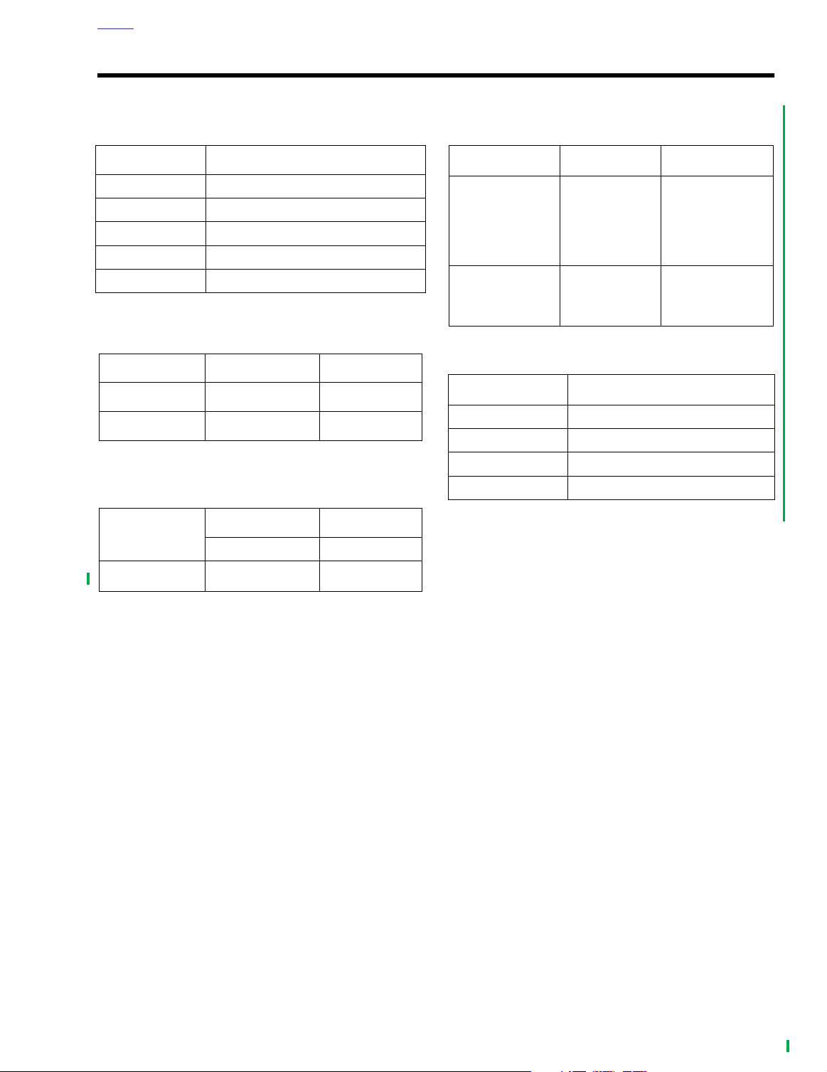
Table 6-1. Gear Ratios
GEAR RATIO
1 10.11
26.958
34.953
43.862
53.15
Table 6-2. Primary Chain Free Play
FREE PLAY IN. MM
COLD Engine
HOT Engine
5/8-7/8 15.9-22.2
3/8-5/8 9.5-15.9
Table 6-3. Primary Chaincase Lubricant
OZ ML
Amount
32 946
Table 6-4. Drive Belt Deflection
DEFLECTION
On Jiffy Stand
Without Rider or
Luggage with 10-
psi (69 kPa) in
Rear Shocks
Motorcycle
Upright With rear
Wheel in Air
IN. MM
1/4-5/16
at 10 lbs force
3/16-1/4
at 10 lbs force
Table 6-5. Sprockets
SPROCKET
Engine 25
Clutch 36
Tr ansmission 32
Rear wheel 70
NUMBER OF TEETH
6.4-7.9
at 4.5 kg force
4.8-6.4
at 4.5 kg force
Part No.
Quart Bottle
99824-03/00QT
2004 FLHTCSE: Drive 6-1
Page 2

HOME
TORQUE VALUES 6.2
ITEM TORQUE NOTES
Clutch inspection cover 84-108
in-lbs
10-12 Nm page 6-3
6-2 2004 FLHTCSE: Drive
Page 3

HOME
9992
1. Outer retainer clip
2. Release bearing plate
3. Push rod retainer
4. Release bearing
2
1
4
3
f1209a6x
1
3
5
2
4
CLUTCH RELEASE BEARING 6.3
REMOVAL
1WARNING1WARNING
To prevent accidental vehicle start-up, which could
cause death or serious injury, remove maxi-fuse before
proceeding. (00251a)
1. Remove Maxi-Fuse.
2. Remove clutch inspection cover.
3. See Figure 6-1. Remove outer retainer clip (1).
4. Pull out release bearing plate (2) with push rod.
5. Remove push rod retainer (3).
6. Press out bearing (4).
INSTALLATION
1. See Figure 6-1. Pressing on the outer race, press a
bearing (4) into plate (2).
2. Assemble push rod to plate (2).
3. Snap in push rod retainer (3).
4. Slide push rod and clutch release bearing through clutch
pack to secondary clutch actuator.
5. Snap in outer retainer (1).
6. See Figure 6-2. Install clutch inspection cover. In
sequence, tighten fasteners to 84-108
Nm).
7. Install Maxi-Fuse.
in-lbs
new
(10-12
Figure 6-1. Clutch Release Bearing
Figure 6-2. Clutch Inspection Cover Torque Sequence
2004 FLHTCSE: Drive 6-3
Page 4

HOME
NOTES
6-4 2004 FLHTCSE: Drive
 Loading...