

Page 1
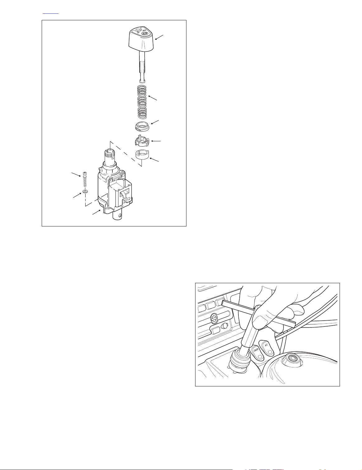
H
f2115x8x
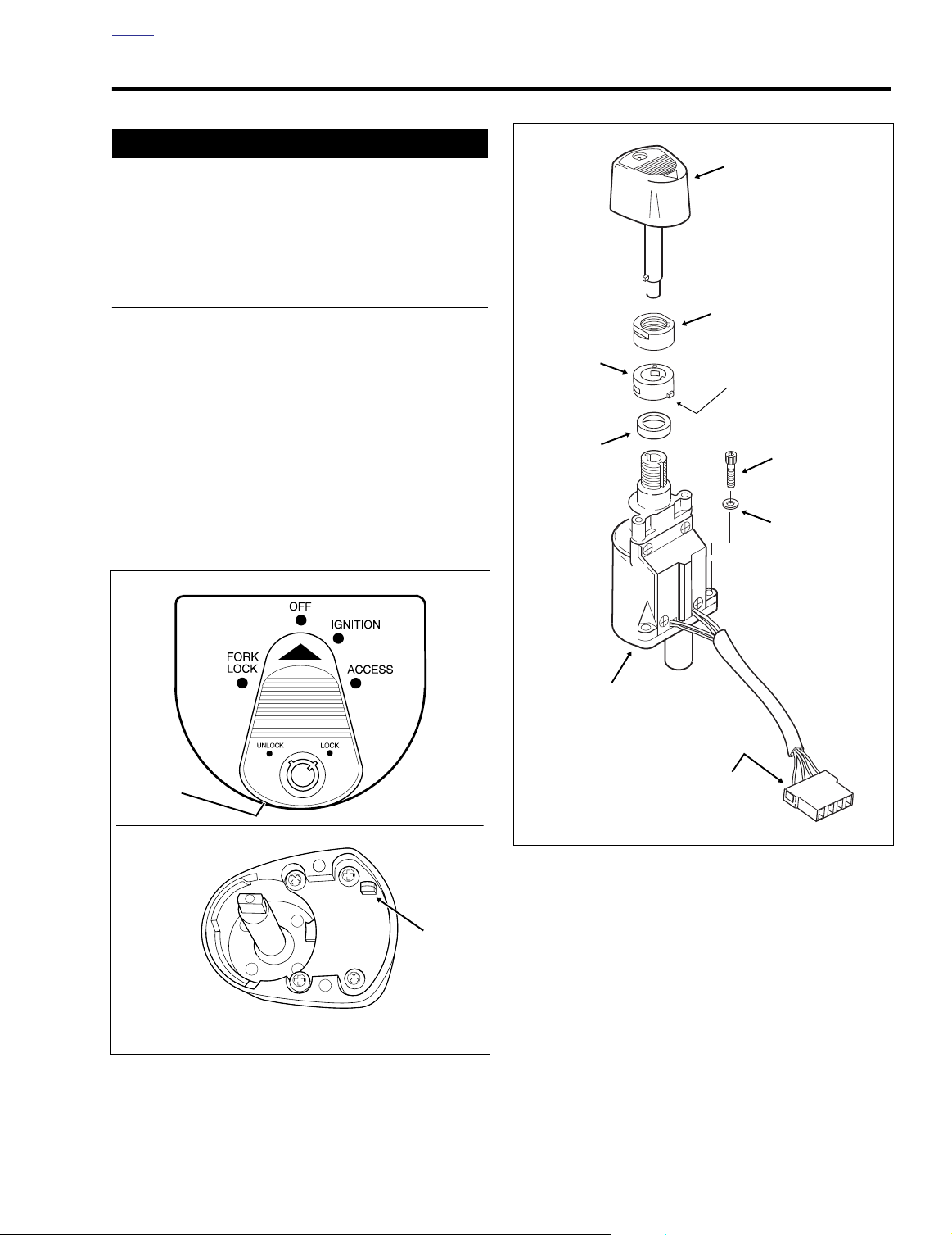
Socket
Screw
Flat
Washer
Switch
Housing
4-Place
Packard
Connector
Spacer
Collar
Nut
Knob
Tab
Down and Forward
OME
IGNITION/LIGHT KEY SWITCH AND FORK LOCK 8.18
1WARNING1WARNING
DO NOT modify the ignition/light key switch wiring to
disable the automatic-on headlamp feature. High visibility is an important safety consideration for motorcycle
riders. Ensure that the headlamp is on at all times. Failure to do so could result in death or serious injury.
FLHT/C/U, FLTR (DOMESTIC)
REMOVAL
1. Remove the outer fairing. See Section 2.29 UPPER
FAIRING/WINDSHIELD (FLHT/C/U), OUTER FAIRING/
WINDSHIELD, REMOVAL.
2. To remove the ignition switch knob, insert the Ignition
Switch key and turn to the UNLOCK position. Leaving
the key installed, rotate the knob to ACCESS. Depressing the release button at bottom (left side) with a small
screwdriver, push key down and turn an additional 60
degrees in a counter-clockwise direction. Lift and
remove knob. See Figure 8-61.
f1240x2x
Button
f1476x8x
Figure 8-61. Ignition Switch Knob Release Button
TOP VIEW
Button
BOTTOM VIEW
Figure 8-62. Ignition Switch Assembly (Domestic)
3. Using a 7/8 inch wrench on flats, loosen switch nut and
remove from threaded post of ignition switch housing.
Remove collar and spacer. See Figure 8-62.
4. Using a T27 TORX drive head, remove the two screws
(with flat washers) that secure fairing cap to left and right
sides of inner fairing.
5. Remove the switch position plate by pulling tabs from
slots in fairing cap. If necessary, raise the fairing cap
slightly to facilitate removal.
2004 Touring: Electrical 8-49
Page 2
H
OME
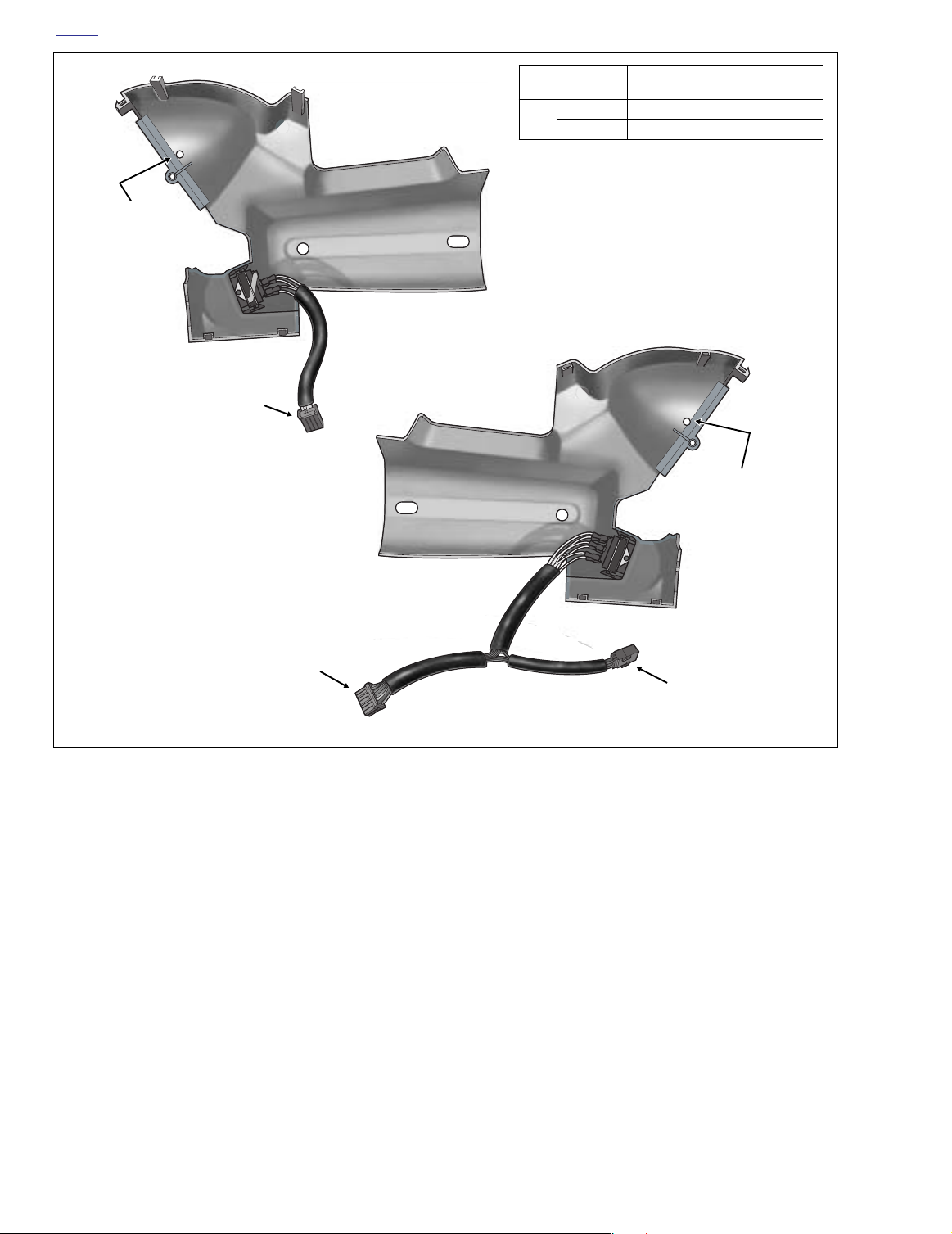
6. With the forks turned fully to the left, disconnect the Fairing cap switch connector [105], 12-place Multilock
(black), from behind right side of fairing cap. Depress the
button on the plug side of the connector to pull apart the
pin and socket halves.
7. Remove the fairing cap from the motorcycle. See Figure
8-63.
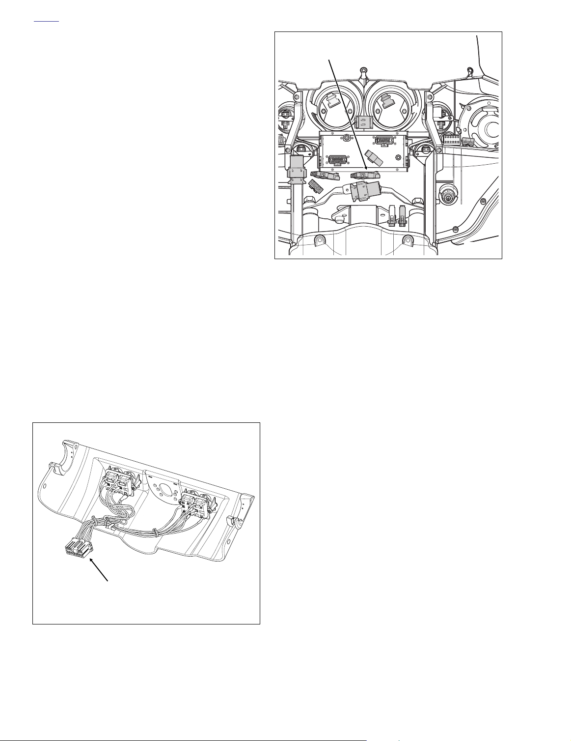
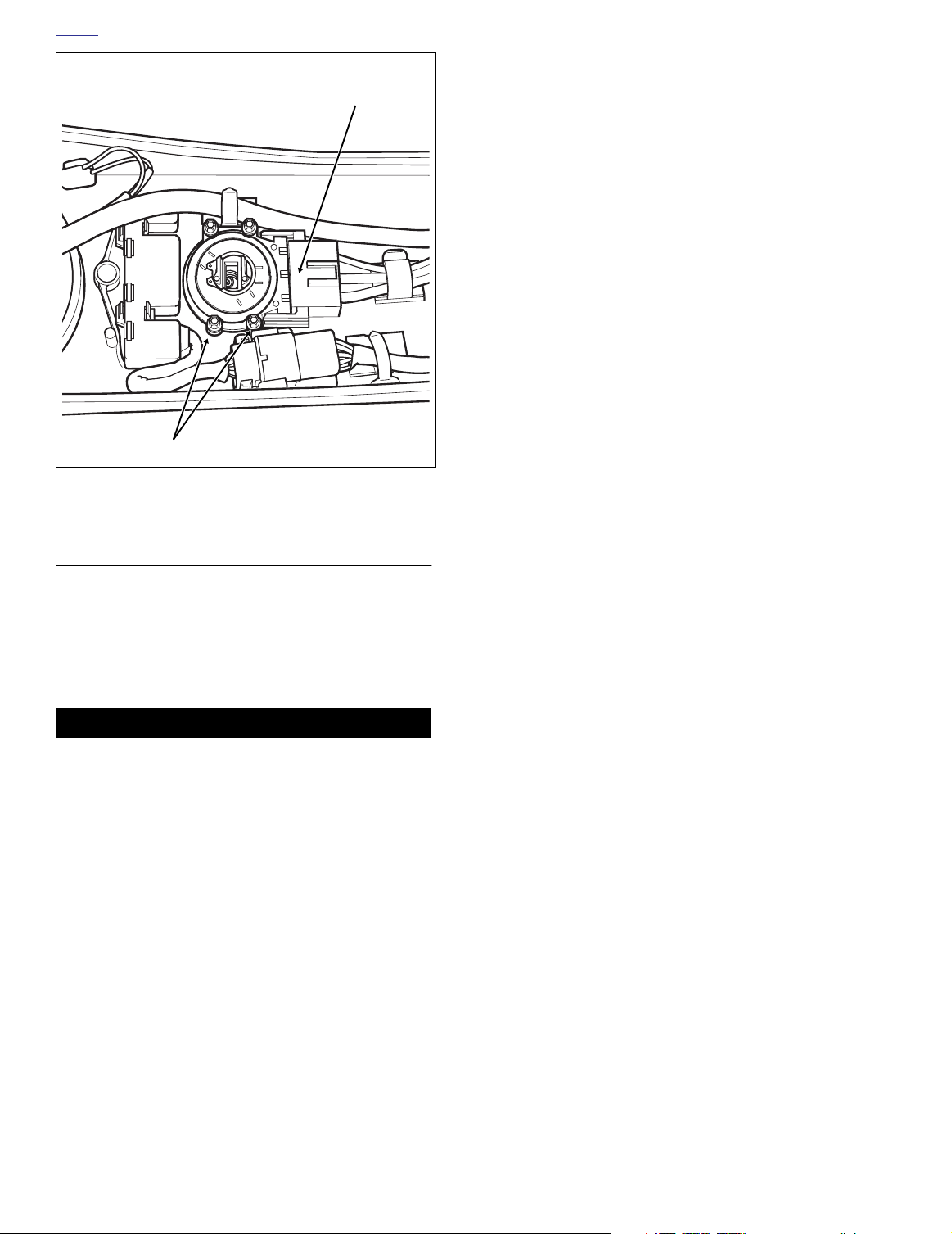
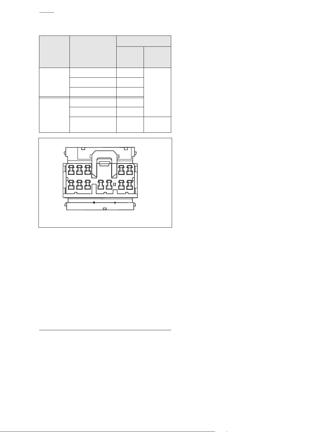
8. Locate the Ignition switch connector [33], 4-place Packard, at bottom of radio. Slide connector off anchor and
separate pin and socket halves. See Figure 8-64.
9. Remove the socket screws (with flat washers) and lift the
switch housing from the upper fork bracket bore. Route
the Ignition switch connector to rear of inner fairing and
remove switch housing from the vehicle.
INSTALLATION
1. Slide base of ignition switch into bore of upper fork
bracket. Install screws (with flat washers) and tighten to
36-60
in-lbs
(4.1-6.8 Nm).
2. Route the Ignition switch connector [33], 4-place Packard, to front of inner fairing. Mate pin and socket halves
of connector and install onto anchor at bottom of radio.
See Figure 8-64.
3. Verify that the rubber grommets are installed on each
side of the fairing cap. Barbs on cap fit into holes in
grommets.
4. Connect the Fairing cap switch connector [105], 12place Multilock (black), on the right side of fairing cap.
5. With the forks turned fully to the left, install fairing cap
over ignition switch housing.
f1305b2x
Ignition Switch
Connector [33]
f2238x8x
Figure 8-64. Ignition Switch Connector Location
(FLHT/C/U)
6. Install switch position plate fitting tabs in slots of fairing
cap. Plate snaps in place when properly installed. Exercise care to avoid breaking tabs. Replace plate if tabs
are broken.
7. Using a T27 TORX drive head, start two fairing cap
screws (with flat washers). Verify that grommets in fairing cap fully capture handlebar along with throttle and
clutch cables.
8. Slide spacer over threaded post of ignition switch housing until it contacts switch position plate. Slide collar over
post with the tab side down (and forward). Install nut,
and using a 7/8 inch wrench on flats, tighten to 50-70
lbs
(5.7-7.9 Nm).
in-
Fairing Cap
Switch Connector [105]
12-Place Multilock
Figure 8-63. Fairing Cap Assembly (FLHT/C/U)
8-50 2004 Touring: Electrical
9. With the red arrow pointing toward the ACCESS position, install the ignition switch knob. Turn key clockwise
to UNLOCK position and then turn knob to OFF.
10. Using a T27 TORX drive head, tighten two fairing cap
screws to 25-30
in-lbs
(2.8-3.4 Nm).
11. Verify operation of both the ignition switch and fork lock
assemblies.
12. Install the outer fairing. See Section 2.29 UPPER FAIR-
ING/WINDSHIELD (FLHT/C/U), OUTER FAIRING/
WINDSHIELD, INSTALLATION.
Page 3
H
f2086x8x
OME
FLHT/C/U, FLTR (INTERNATIONAL)
REMOVAL
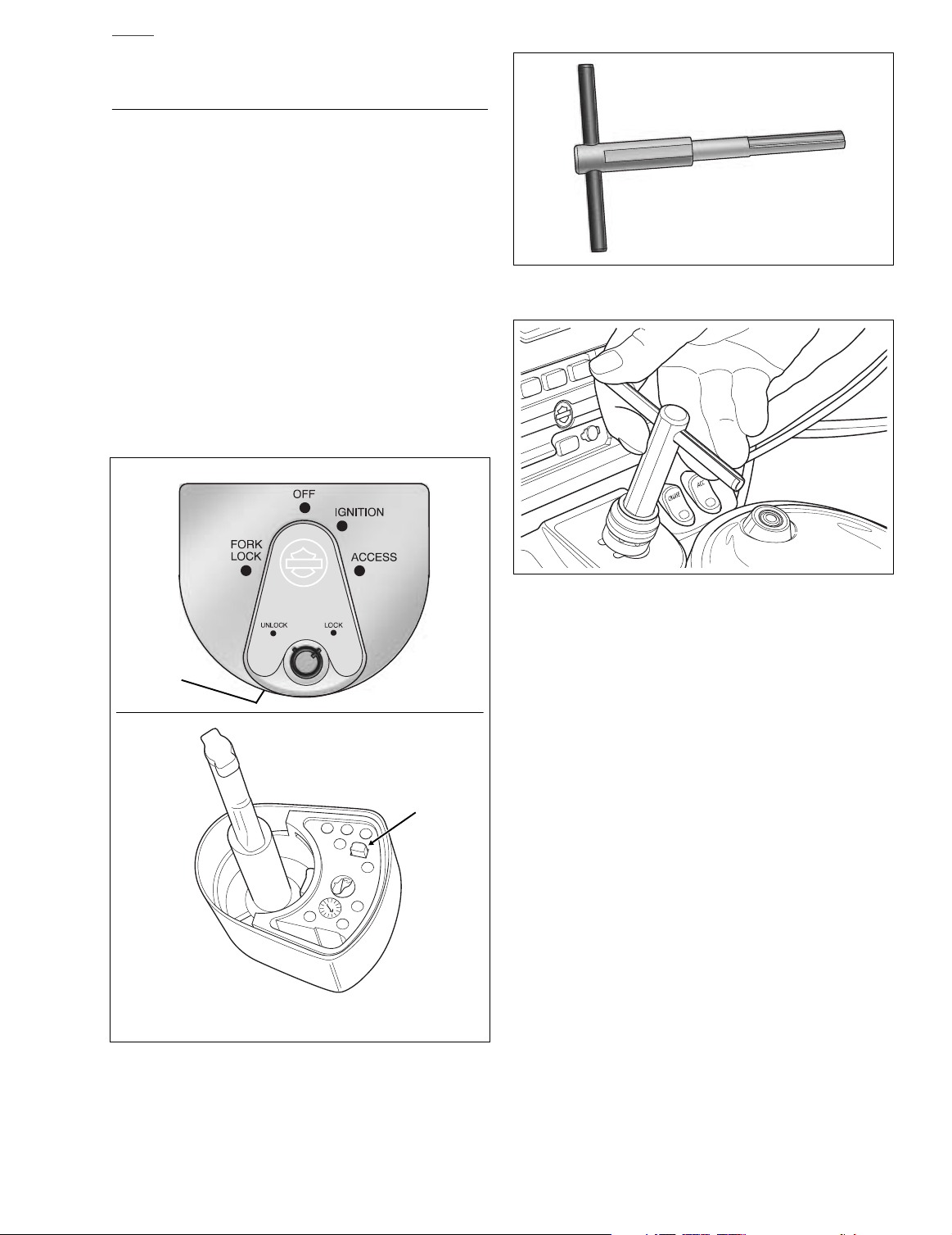
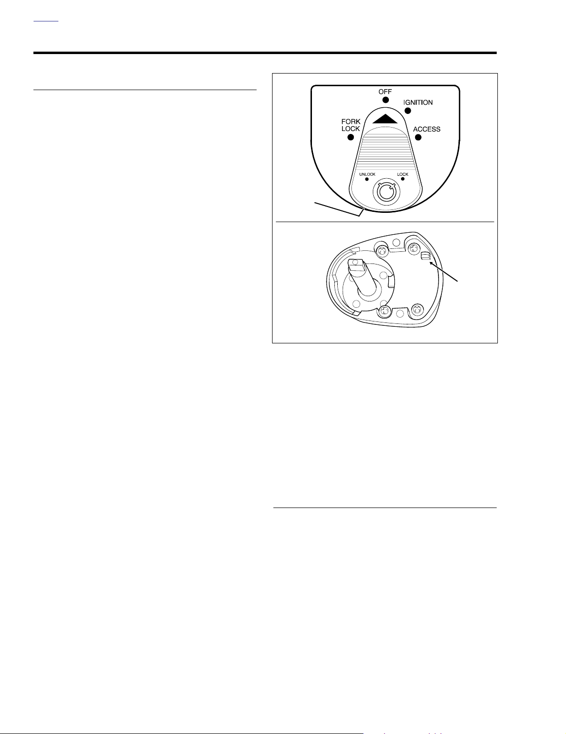
1. Remove the ignition switch knob as follows:
a. Insert the ignition switch key and turn to the
UNLOCK position. Leave the key installed in the
ignition switch knob.
b. Tu rn the front forks to the left fork stop and rotate
the knob to FORK LOCK.
c. Depressing the release button at bottom (left side)
with a small screwdriver, push key down and turn 60
degrees in a counter-clockwise direction. See Fig-
ure 8-65.
d. Lift and remove knob. Be aware that spring will drop
out of bore at underside of knob when removed.
Figure 8-66. Ignition Switch Alignment Tool
(Part No. HD-45962)
f2080x8x
Button
f2097x8x
Figure 8-65. Ignition Switch Knob Release Button
TOP VIEW
Button
BOTTOM VIEW
Figure 8-67. Bottom Alignment Tool in Threaded Post
and Rotate to Desired Position
NOTE
After removal of the knob, the IGNITION SWITCH ALIGNMENT TOOL (HD-45962) may be used to move the switch to
other positions as required. Insert tool until bottom of handle
contacts top of threaded post, and then rotate handle in a
clockwise direction to the selected position. See Figure 8-67.
2. Turn the front forks to the right fork stop, and using a 7/8
inch open end wrench on flats, remove nut from
threaded post of ignition switch housing.
3. Pull collar and spacer from threaded post.
4. Remove the switch position plate by pulling tabs from
slots in fairing cap (FLHT/C/U) or instrument nacelle
(FLTR).
5.
FLTR:
Remove the instrument nacelle. See Section 2.30
UPPER FAIRING/WINDSHIELD (FLTR), INSTRUMENT
NACELLE, REMOVAL.
FLHT/C/U:
UPPER FAIRING/WINDSHIELD (FLHT/C/U), FAIRING
CAP, REMOVAL.
Remove the fairing cap. See Section 2.29
2004 Touring: Electrical 8-51
Page 4
H
OME
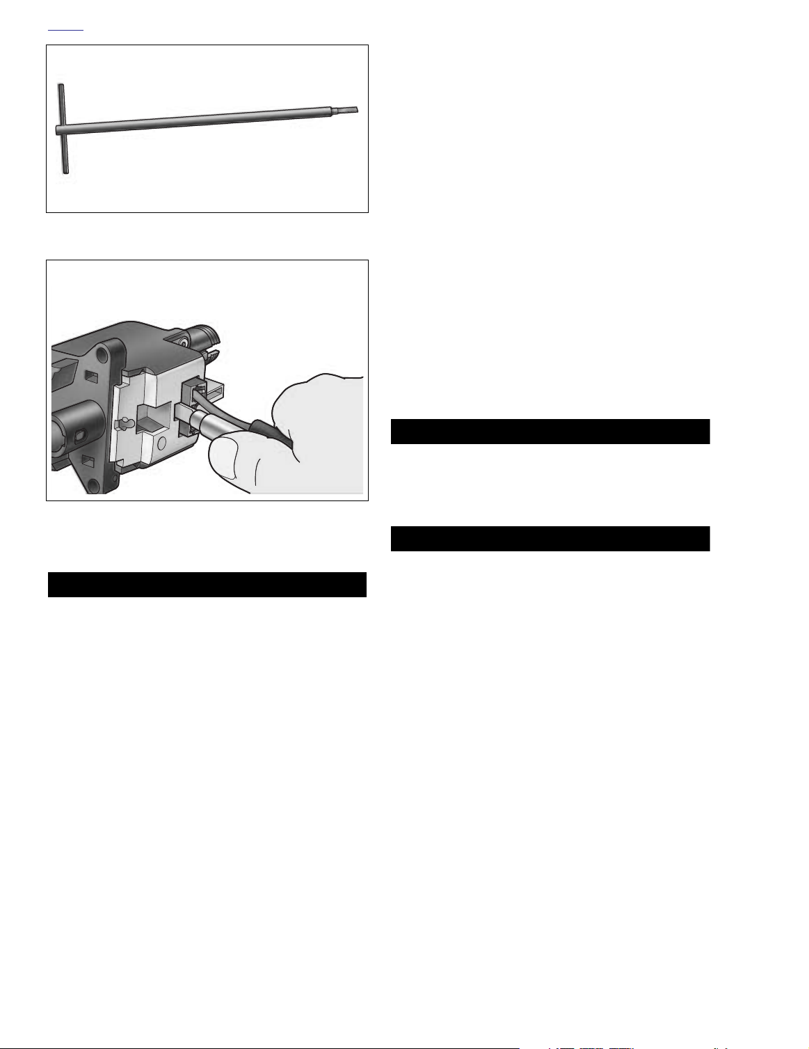
Figure 8-68. Ignition Switch Connector Remover
(Part No. HD-45961)
f2090x8x
8. Disconnect the ignition switch jumper harness connector
[33], 3-place Packard, at front of ignition switch housing.
Proceed as follows:
a. Obtain the IGNITION SWITCH CONNECTOR
REMOVER (HD-45961). See Figure 8-68.
b. Gently insert end of tool into slot in ignition switch
housing until it stops.
c. Grasping jumper harness conduit and tool, pull both
at the same time to release socket housing from
ignition switch housing. See Figure 8-69.
NOTE
For instructions on properly removing and installing jumper
harness terminals, see APPENDIX B.4 AUTOFUSE ELEC-
TRICAL CONNECTOR.
INSTALLATION
1. Install Ignition switch jumper harness connector [33], 3place Packard, at front of
2. Slide base of ignition switch housing into bore of upper
fork bracket.
new
ignition switch housing.
Figure 8-69. Pull Jumper Harness Conduit and Tool
to Release Socket Housing
1WARNING1WARNING
Always wear proper eye protection when drilling. Flying
debris may result in eye injury.
6. Remove the two break-away screws at the base of the
ignition switch housing. Proceed as follows:
a. Use a center punch to make a pilot hole at the top of
each break-away screw.
b. Install a 1/8 inch left handed bit in drill and set the
drill to Reverse. Positioning the bit in the pilot hole,
spin out the break-away screws.
NOTE
If the above method fails, use a 3/16 inch bit with long shank
to carefully drill off heads of break-away screws. Use a pliers
to unthread the shafts from the upper fork bracket.
7. Remove ignition switch housing from upper fork bracket
bore.
CAUTION
Verify that the threads in the upper fork bracket are clean
and in good condition. Dirty and/or damaged threads
may cause the heads of the break-away screws to snap
off before the switch housing is properly tightened.
CAUTION
Exercise care to avoid losing heads of break-away
screws in vehicle. Vibration may cause captured heads
to scratch finished surfaces, chafe wires or cause other
damage.
3. Install
4.
5. Install switch position plate fitting tabs in slots of fairing
6. Install spacer over threaded post of ignition switch hous-
new
break-away screws at base of ignition switch
housing. Turn screws in a clockwise direction until heads
snap off.
FLTR:
Install the instrument nacelle. See Section 2.30
UPPER FAIRING/WINDSHIELD (FLTR), INSTRUMENT
NACELLE, INSTALLATION.
FLHT/C/U:
UPPER FAIRING/WINDSHIELD (FLHT/C/U), FAIRING
CAP, INSTALLATION.
cap (FLHT/C/U) or instrument nacelle (FLTR). Plate
snaps in place when properly installed. Exercise care to
avoid breaking tabs. Replace plate if tabs are broken.
ing until it contacts switch position plate. Orient spacer
so that the widest side is forward and the inside tabs fit
in slots of post. See Figure 8-70.
Install the fairing cap. See Section 2.29
8-52 2004 Touring: Electrical
Page 5
H
f2087x8x
OME
1. Knob
2. Spring
3. Nut
4. Collar
5. Spacer
6. Break-Away Screw
7. Flat Washer
8. Switch Housing
12. Knob was removed in ACCESS or switch may have
1
2
3
been moved out of the FORK LOCK position. Proceed
as follows:
a. Insert alignment tool until bottom of handle contacts
top of threaded post, and holding front forks at the
left fork stop, rotate handle of tool in a counterclockwise direction until fork locks. See Figure 8-67.
b. Remove tool and repeat step 10.
c. If knob does not install properly, move to step 13.
13. Detent and switch position lugs are misaligned. This can
occur when the alignment tool (or ignition switch knob) is
rotated before it is properly bottomed in the ignition
switch housing. Proceed as follows:
4
5
6
7
8
Figure 8-70. Ignition Switch Assembly (International)
7. Slide collar over threaded post until it contacts spacer.
Orient collar so that the outside tab is forward and the
inside tabs fit in slots of post.
8. Thread nut onto post with the lipped side down and the
smaller OD topside. Turn the front forks to the right fork
stop, and using a 7/8 inch Open End Crow Foot on flats,
tighten nut to 125-150
9. Install spring into bore at underside of knob.
10. With the knob pointing toward the FORK LOCK position,
insert shaft into threaded post. Holding the knob down,
turn key clockwise to UNLOCK. An audible “click” should
be heard when knob and switch are properly engaged.
Release knob and then rotate through all four switch
positions to verify proper operation.
If knob will not install properly, move to step 11.
11. Proceed as follows:
a. Verify that button at bottom of knob is depressed
and key is turned 60 degrees beyond the UNLOCK
position. See Figure 8-65.
b. Repeat step 10.
c. If knob does not install properly, move to step 12.
in-lbs
(14.1-16.9 Nm).
f2116x8x
a. Reinstall knob inserting shaft into threaded post and
gently rotate knob until it drops into the partially
installed position. Take note of the position of the
knob, that is, whether it is pointing toward the rear,
or to ACCESS, IGNITION or OFF.
b. Remove knob and insert alignment tool so that the
bottom of the handle is approximately 1/2-3/4 inch
(12.7-19.1 mm) from the top of the threaded post,
and then hold. See Figure 8-71.
c. Rotate alignment tool in a counter-clockwise
direction the number of positions needed to get to
FORK LOCK. For example, if the knob dropped into
the partially installed position at IGNITION in step
13(a), rotate the alignment tool two positions in a
counter-clockwise direction. Or if the knob was
pointing toward the rear when it dropped, rotate the
alignment tool four positions in a counter-clockwise
direction or one position in a clockwise direction.
Repeat step 10.
Figure 8-71. Rotate Alignment Tool Without Bottoming
2004 Touring: Electrical 8-53
Page 6
H
OME
Ignition/Light
Key Switch Connector [33]
Screw
Figure 8-72. Instrument Console (FLHR/C)
f2095x8x
FLHR/C/S
IGNITION/LIGHT KEY SWITCH
Removal
1. Remove seat. See Section 2.24 SEAT, REMOVAL.
1WARNING1WARNING
To protect against shock and accidental start-up of vehicle, disconnect the negative battery cable before proceeding. Inadequate safety precautions could result in
death or serious injury.
2. Unthread bolt and remove battery negative cable (black)
from battery negative (-) terminal.
3. Carefully cut anchored cable strap securing main harness bundle, instrument console conduit, and fuel vapor
vent tube to left side of frame backbone.
6. Raise instrument console and bend back flexible clamp
on canopy to release main harness conduit. Depress
button on socket side and remove fuel level sender/fuel
pump connector [141], 3-place Mini-Deutsch.
7. Lay a clean shop towel on forward part of rear fender.
Lift the instrument console from fuel tank and lay upside
down on shop towel.
8. Pull external latches outward to disconnect ignition/light
key switch connector [33], 3-place Packard. See Figure
8-72.
9. Remove four screws to release switch from console.
Installation
1. Align holes in
ure 8-72.
2. Start four screws and alternately tighten to 20-30
(2.3-3.4 Nm) in a crosswise pattern.
3. Connect ignition/light key switch connector [33], 3-place
Packard.
4. Slide head of console mounting bolt into slot at top of
canopy.
5. Moving instrument console toward installed position,
install fuel level sender/fuel pump connector [141], 3place Mini-Deutsch, at top of canopy. Bend flexible
clamp to capture main harness conduit.
6. Align hole in instrument console with console mounting
bolt and place into position on fuel tank.
7. Install acorn nut at top of instrument console and tighten
to 50-90
Phillips screw and large flat washer (absent on FLHRS
models). Tighten screw to 36-60
8. On FLHRS models only, install bolt (with flat washer) to
secure rear of fuel tank and instrument console bracket
to frame backbone. Tighten bolt to 15-20 ft-lbs (20-27
Nm).
9. Snap anchor of
frame backbone. Tighten cable strap capturing main harness bundle, instrument console conduit, and fuel vapor
vent tube. Cut any excess cable strap material.
10. Insert bolt through battery negative cable (black) into
threaded hole of battery negative (-) terminal. Tighten
bolt to 60-96
11. Install seat. See Section 2.24 SEAT, INSTALLATION.
new
switch with those in console. See Fig-
in-lbs
(5.7-10.2 Nm). If present, also install
in-lbs
(4.1-6.8 Nm).
new
cable strap into hole on left side of
in-lbs
(6.8-10.9 Nm).
in-lbs
4. Remove acorn nut from instrument console. If present,
also remove Phillips screw and large flat washer (absent
on FLHRS models).
5. On FLHRS models only, remove bolt (with flat washer) to
free rear of fuel tank from frame backbone. Removal of
rear bolt also releases instrument console bracket.
8-54 2004 Touring: Electrical
FORK LOCK
Removal
1. Remove the handlebar clamp shroud. See Section 2.31
WINDSHIELD/HEADLAMP NACELLE (FLHR/C/S),
NACELLE REMOVAL (FLHR/C), steps 1-11, or
NACELLE REMOVAL (FLHRS), steps 1-7.
Page 7
H
OME
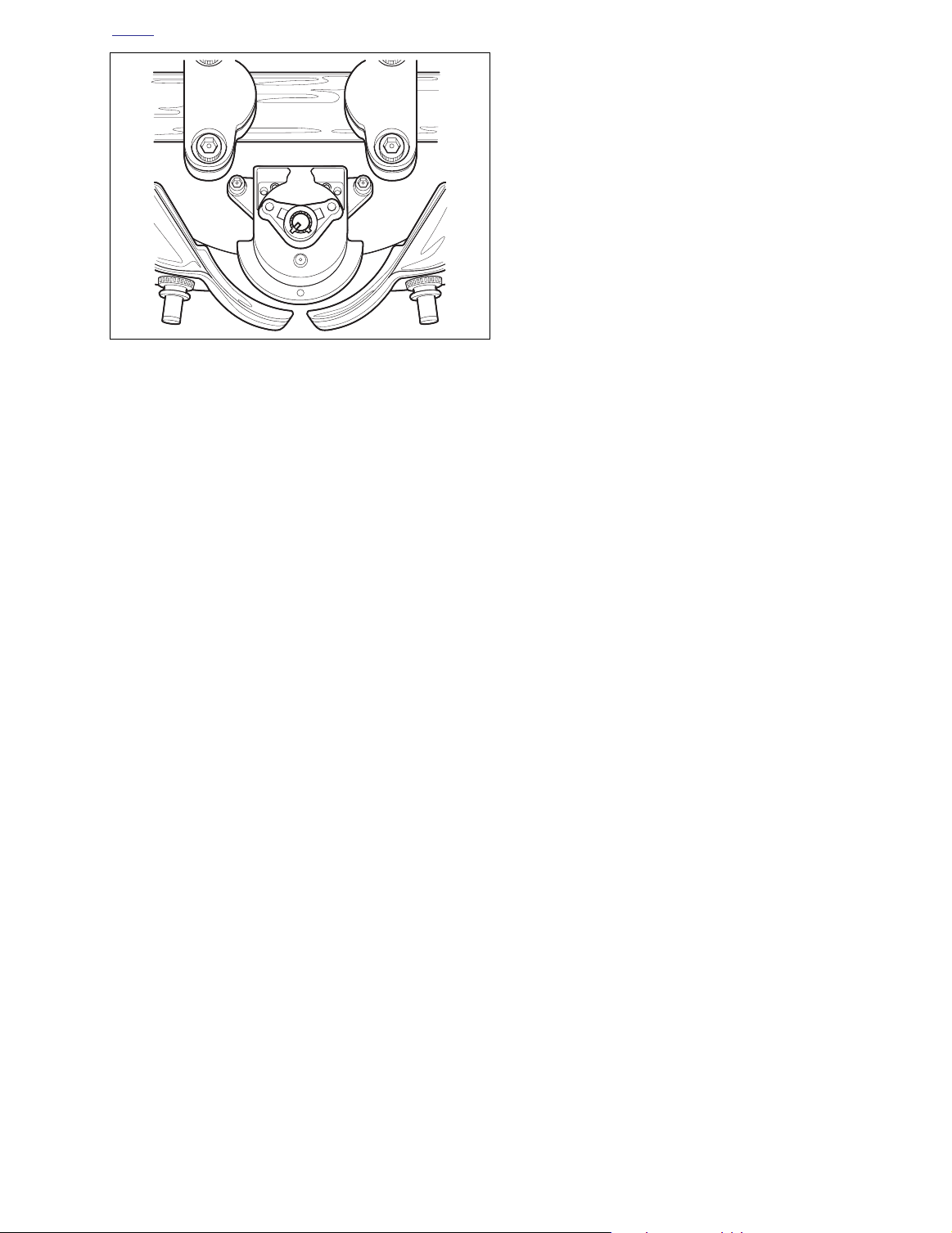
f2101x8x
Figure 8-73. Fork Lock (FLHR/C/S)
2. Start acorn nuts on both the left and right side fork studs
to keep halves of headlamp nacelle on motorcycle.
3. Remove two allen head socket screws (with flat washers) and pull fork lock assembly from upper fork bracket
bore. See Figure 8-73.
3. Install the handlebar clamp shroud. See Section 2.31
WINDSHIELD/HEADLAMP NACELLE (FLHR/C/S),
NACELLE INSTALLATION (FLHR/C), steps 3-15, or
NACELLE INSTALLATION (FLHRS), steps 5-13.
NOTE
On HDI models, use a center punch to make a pilot hole at
the top of each break-away screw. Install a 1/8 inch left
handed bit in drill and set the drill to reverse. Positioning the
bit in the pilot hole, spin out the break-away screws.
Installation
1. Install
2. Install two allen head socket screws (with flat washers)
On HDI models, install
clockwise direction until heads snap off. Verify that threads in
upper fork bracket are clean and in good condition or heads
may break off before fork lock assembly is properly tightened.
Avoid losing heads of screws in vehicle as vibration may
cause captured heads to scratch finished surfaces, chafe
wires or cause other damage.
new
fork lock assembly into bore of upper fork
bracket. See Figure 8-73.
and alternately tighten to 36-60
NOTE
new
break-away screws and turn in a
in-lbs
(4.1-6.8 Nm).
2004 Touring: Electrical 8-55
Page 8
H
OME
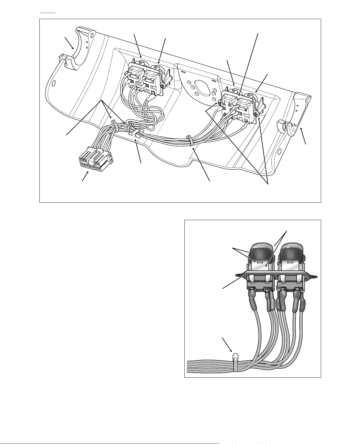
FAIRING CAP SWITCHES (FLHTC/U) 8.19
REMOVAL
1. Partially disassemble domestic ignition switch as follows:
NOTE
For partial disassembly of HDI ignition switch, see Section
8.18 IGNITION/LIGHT KEY SWITCH AND FORK LOCK,
FLHT/C/U, FLTR (INTERNATIONAL), REMOVAL, steps 1-4.
a. See Figure 8-74. To remove the ignition switch
knob, insert the Ignition Switch key and turn to the
UNLOCK position. Leaving the key installed, rotate
the knob to ACCESS. Depressing the release button at bottom (left side) with a small screwdriver,
push key down and turn an additional 60 degrees in
a counter-clockwise direction. Lift and remove knob.
b. Using a 7/8 inch wrench on flats, loosen switch nut
and remove from threaded post of ignition switch
housing. Remove collar and spacer.
c. Gently remove the switch position plate by pulling
tabs from slots in fairing cap. If necessary, raise the
fairing cap slightly to facilitate removal.
2. Using a T27 TORX drive head, remove the two screws
(with flat washers) that secure fairing cap to left and right
sides of inner fairing.
3. With the forks turned fully to the left, disconnect the fairing cap switch connector [105], 12-place Multilock
(black), from behind right side of fairing cap. Depress the
button on the socket terminal side of the connector and
pull apart the pin and socket halves.
4. Remove the fairing cap from the motorcycle. See Figure
8-75.
5. Bend back the flexible clamp to release switch wires
from the inboard side of the fairing cap. Carefully cut
cable straps to free wires from bundles.
f1240x2x
Button
BOTTOM VIEW
f1476x8x
Figure 8-74. Ignition Switch Knob Release Button
10. Remove the appropriate terminals from the socket housing.
NOTE
For instructions on properly removing wire terminals, see
APPENDIX B.2 AMP MULTILOCK ELECTRICAL CONNEC-
TORS, REMOVING SOCKET/PIN TERMINALS.
TOP VIEW
Button
6. Using a T25 TORX drive head, remove two screws to
release switch bracket.
7. Gently pry two latches on bracket outward to release
tabs on switch. Remove switch from bracket. See Figure
8-76.
8. If replacing Cruise or Speaker Switch, cut Black/Green
wire lead halfway between Cruise and Speaker Switch
terminals.
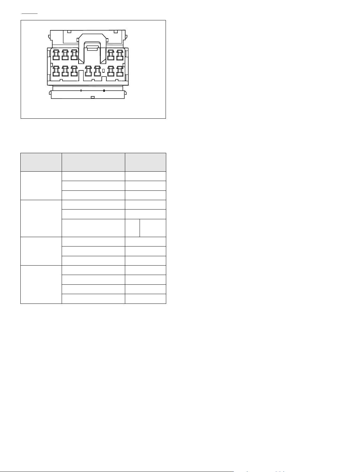
9. Follow the wires of the faulty switch to the socket housing, or reference Figure 8-77 and Table 8-10 for the
applicable chamber numbers. For wire location purposes, numbers are stamped into the secondary locks of
both the pin and socket housings.
8-56 2004 Touring: Electrical
INSTALLATION
1. Feeding wires through bracket, place
position. Engage tabs on switch in slots of latches and
then gently bend tabs upward to lock position of switch
in bracket.
2. Install terminals into socket housing.
NOTE
For instructions on properly installing wire terminals, see
APPENDIX B.2 AMP MULTILOCK ELECTRICAL CONNEC-
TORS, INSTALLING SOCKET/PIN TERMINALS.
new
switch into
Page 9
H
f1304b2x
Cable
Strap
Switch
Bracket
Tab
Latch
OME
Grommet
Cable
Strap
Socket Housing
12-place Multilock
Fairing Cap Switch Connector [105]
Accessory
Switch
Flexible
Clamp
Cruise
Switch
Speaker
Cable
Strap
Switch
Switch
Bracket
Spotlight
Switch
Switch Bracket
TORX Screws
f1305b2x
Grommet
Figure 8-75. Fairing Cap (Inboard Side) - Ultra Model Shown
3. If Cruise or Speaker Switch was replaced, butt splice
Black/Green wire lead between Cruise and Speaker
Switch terminals.
NOTE
For detailed butt splicing information, see APPENDIX B.5
SEALED BUTT SPLICE CONNECTORS.
4. Using a T25 TORX drive head, install two screws to
secure switch bracket to fairing cap.
5. Install
new
cable straps to capture wire bundles and
then secure switch wires to the fairing cap using the flexible clamp. Route the wires as shown in Figure 8-75.
6. Verify that the rubber grommets are installed on each
side of the fairing cap. Barbs on cap fit into holes in
grommets.
7. Connect the fairing cap switch connector [105], 12-place
Multilock (black), on the right side of fairing cap.
8. With the forks turned fully to the left, install fairing cap
over ignition switch housing. Verify that grommets in fairing cap fully capture handlebar along with throttle and
clutch cables.
9. Start two fairing cap screws (with flat washers). Using a
T27 TORX drive head, alternately tighten screws to 2530
in-lbs
(2.8-3.4 Nm).
Figure 8-76. Bend Latches Outward to Release Tabs
2004 Touring: Electrical 8-57
Page 10
H
OME
10. Assemble domestic ignition switch as follows:
3
1
2
– AMP
7910
8
6
Secondary Locks Open
4
5
5
12
11
f1287b2x
Figure 8-77. Numbers Stamped on Secondary Locks
(Socket Housing Shown)
Table 8-10. Fairing Cap Switches [105]
Switch
Accessory
Cruise
Ultra Only
Spot
Speaker
Ultra Only
Wire Color
Orange/Red 1
Orange 2
Black 3
Orange/Violet 4
Red/Green 5
Black/Green
(Double Lugged)
Ye llow 6
Gray/Black 7
Black 8
Orange/Blue 9
Violet/Orange 10
Brown/Orange 11
Black/Green
Chamber
Number
To
Speaker
12
Switch
To Cruise Switch
NOTE
For assembly of HDI ignition switch, see Section 8.18 IGNI-
TION/LIGHT KEY SWITCH AND FORK LOCK, FLHT/C/U,
FLTR (INTERNATIONAL), INSTALLATION, steps 5-10.
a. Install switch position plate fitting tabs in slots of fair-
ing cap. Plate snaps in place when properly
installed. Exercise care to avoid breaking tabs.
Replace plate if tabs are broken.
b. Slide spacer over threaded post of ignition switch
housing until it contacts switch position plate.
c. Slide collar over post with the tab side down (and
forward).
d. Install nut, and using a 7/8 inch wrench on flats,
tighten to 50-70
in-lbs
(5.7-7.9 Nm).
e. With the red arrow pointing toward the ACCESS
position, install the ignition switch knob. Turn key
clockwise to UNLOCK position and then turn knob
to OFF.
8-58 2004 Touring: Electrical
Page 11
H
OME
INSTRUMENT NACELLE SWITCHES (FLTR) 8.20
REMOVAL
1. Using a T25 TORX drive head, remove screw on left and
right side of instrument bezel.
2. Use thumbs to push tab at rear of bezel from slot in front
of ignition switch. Gently raise free side of bezel until
tabs at front of instrument nacelle become disengaged
from slot at front of bezel (concealed behind decorative
adhesive strip).
3. Raising bezel slightly, remove anchor on ambient temperature sensor from hole in bottom inboard ear of
speedometer bracket.
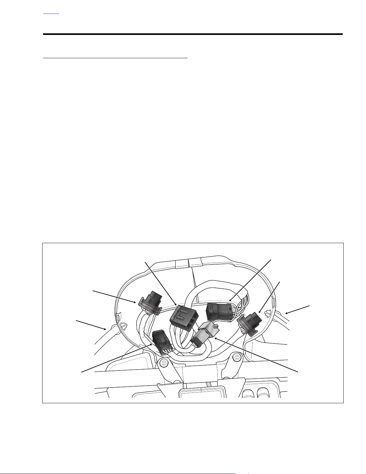
4. See Figure 8-78. Disconnect instruments and indicator
lamps from interconnect harness as follows:
●
Speedometer connector [39], 12-place Packard.
Tachometer connector [108], 12-place Packard.
●
Indicator lamps connector [21], 10-place Multilock.
●
5. Remove bezel from motorcycle.
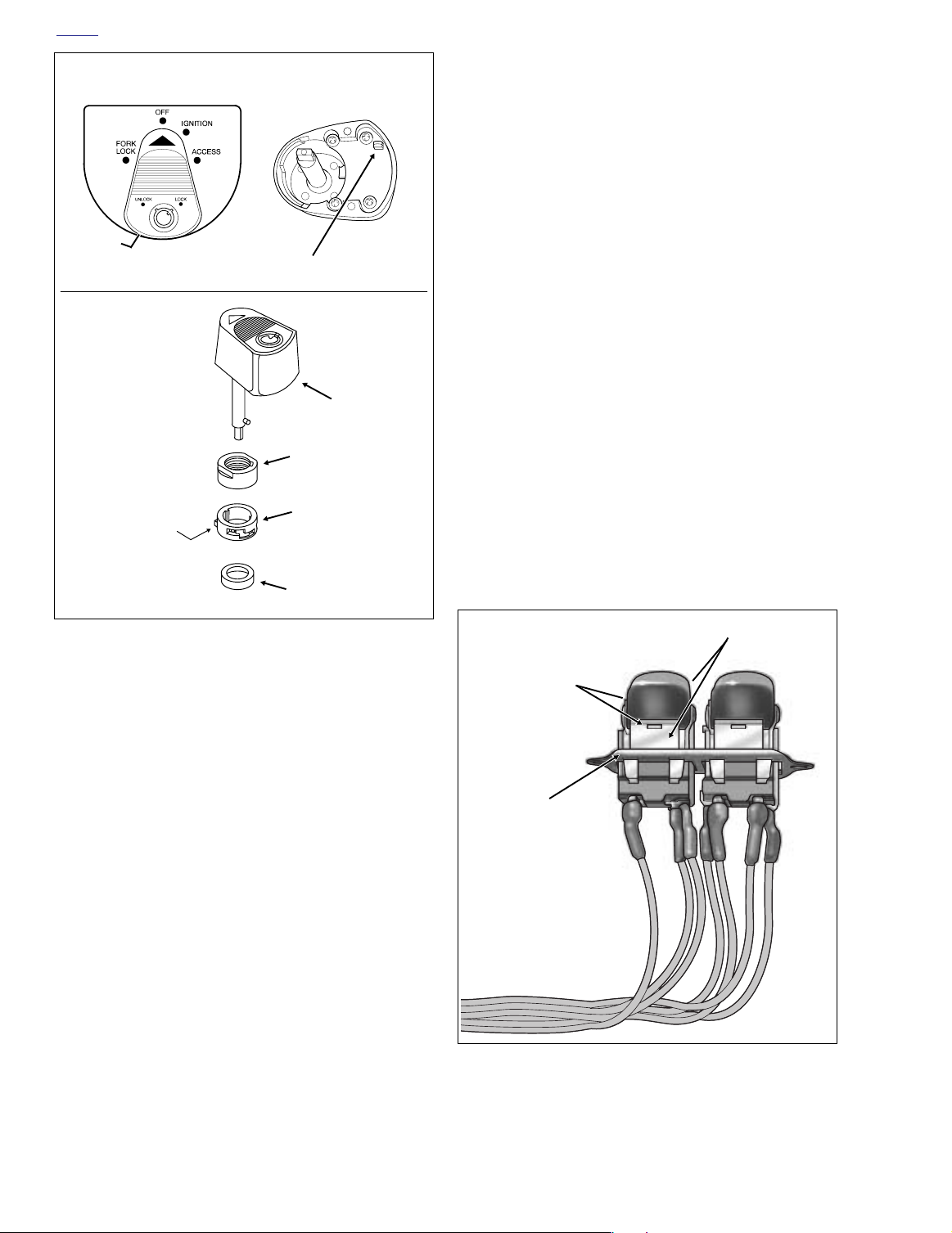
6. Partially disassemble domestic ignition switch as follows:
NOTE
For partial disassembly of HDI ignition switch, see Section
8.18 IGNITION/LIGHT KEY SWITCH AND FORK LOCK,
FLHT/C/U, FLTR (INTERNATIONAL), REMOVAL, steps 1-4.
a. To remove the ignition switch knob, insert the Igni-
tion Switch key and turn to the UNLOCK position.
Leaving the key installed, rotate the knob to
ACCESS. Depressing the release button at bottom
(left side) with a small screwdriver, push key down
and turn an additional 60 degrees in a counterclockwise direction. Lift and remove knob. See
upper frame of Figure 8-79.
b. Using a 7/8 inch wrench on flats, loosen switch nut
and remove from threaded post of ignition switch
housing. Remove collar and spacer. See lower
frame of Figure 8-79.
c. Remove the switch position plate from threaded
post of ignition switch housing.
7. Follow instructions based on location of defective switch.
LEFT SIDE SWITCH
a. See Figure 8-78. Disconnect left side switch from
instrument nacelle switch harness as follows:
f2219x8x
Speedometer
Gauge [39]
Clutch
Cable
Speaker
Switch [105]
Indicator
Lamps [21]
Figure 8-78. Instrument Nacelle (Bezel Removed)
Instrument Nacelle
Switches [105]
Tachometer
Gauge [108]
Throttle
Cables
Ambient
Temperature
Sensor [107]
2004 Touring: Electrical 8-59
Page 12
H
OME
TOP VIEW BOTTOM VIEW
Button
Button
f1240x2x f1476x8x
f1297b2x
Knob
Nut
Tab
Down and Forward
Collar
RIGHT SIDE SWITCHES
a. See Figure 8-78. Disconnect left side switch from
instrument nacelle switch harness as follows:
●
Speaker Switch connector [105], 4-place Multilock.
b. See Figure 8-78. Disconnect instrument nacelle
switches from interconnect harness as follows:
Instrument nacelle switch connector [105], 12-place
●
Multilock.
c. Pull throttle cable clip from hole on right side of
instrument nacelle.
d. Using a T40 TORX drive head, remove two bolts
(with flat washers) to release right side of instrument nacelle from fork side. Move right side of
nacelle to bench area leaving left side on motorcycle. See Figure 8-82.
e. Gently bend back molded retainer to release switch
bracket assembly from instrument nacelle.
f. Carefully pry two latches on bracket outward to
release tabs on switch. Remove switch from
bracket. See Figure 8-80.
g. Remove the appropriate terminals from the socket
and pin housings. Follow the wires of the faulty
switch or reference Table 8-11 for the applicable
chamber numbers. For wire location purposes,
numbers are stamped into the secondary locks. See
Figure 8-81.
Spacer
Figure 8-79. Ignition Switch Knob (Domestic)
●
Speaker Switch connector [105], 4-place Multilock.
b. Pull clutch cable clip from hole on left side of instru-
ment nacelle.
c. Using a T40 TORX drive head, remove two bolts
(with flat washers) to release left side of instrument
nacelle from fork side.
d. Unthread rubber boot from odometer reset switch,
and while carefully removing left side instrument
nacelle from motorcycle, pull odometer reset switch
from hole. Move left side of nacelle to bench area
leaving right side on motorcycle. See Figure 8-82.
e. Gently bend back molded retainer to release switch
bracket assembly from instrument nacelle.
f. Carefully pry two latches on bracket outward to
release tabs on switch. Remove switch from
bracket. See Figure 8-80.
Latch
Tab
Switch
Bracket
f2215x8x
Figure 8-80. Bend Latches Outward to Release Tabs
8-60 2004 Touring: Electrical
Page 13
H
OME
Instrument Nacelle Switches
Switch
Accessory
Cruise
Table 8-11. Right Side
Chamber Number
Wire Color
Orange/Red 1
Orange 2
Black 3
Orange/Violet 4
Red/Green 5
Black/Green
(Double Lugged)
3
1
2
– AMP
7910
8
6
12-Place
Multilock
Socket
12 4
4
5
5
12
11
4-Place
Multilock
Pin
b. Snap switch bracket into molded retainer in instru-
ment nacelle.
c. While carefully placing left side of instrument
nacelle on motorcycle, slide odometer reset switch
through hole and install rubber boot.
d. See Figure 8-78. Connect left side switch to instru-
ment nacelle switch harness as follows:
Speaker Switch connector [105], 4-place Multilock.
●
e. Using a T40 TORX drive head, install two bolts (with
flat washers) to fasten left side instrument nacelle to
fork side. Alternately tighten bolts to 15-20 ft-lbs
(20-27 Nm).
f. Capture clutch cable in cable clip. Insert cable clip
into hole in left side of instrument nacelle.
g. Move to RIGHT SIDE SWITCHES, step 2.
RIGHT SIDE SWITCHES
a. Place
b. Push terminals through two lengths of conduit to
c. Install terminals into socket or pin housing. See
new
switch into position in bracket. Engaging
tabs on switch in slots of latches, gently bend tabs
upward to lock position of switch in bracket. See
Figure 8-80.
wire end of socket or pin housing. For best results,
push one wire through conduit at a time.
Ta bl e 8-12 and Figure 8-81.
Secondary Locks Open
f1287b2x
Figure 8-81. Numbers Stamped on Secondary Locks
(Socket Housing Shown)
NOTE
For instructions on properly removing wire terminals, see
APPENDIX B.2 AMP MULTILOCK ELECTRICAL CONNEC-
TORS, REMOVING SOCKET/PIN TERMINALS.
h. Carefully pull wires to draw terminals through con-
duit to backside of switch. For best results, pull one
wire at a time.
INSTALLATION
1. Follow instructions based on location of defective switch.
LEFT SIDE SWITCH
a. Place
new
switch into position in bracket. Engaging
tabs on switch in slots of latches, gently bend tabs
upward to lock position of switch in bracket.
NOTE
For instructions on properly installing wire terminals, see
APPENDIX B.2 AMP MULTILOCK ELECTRICAL CONNEC-
TORS, INSTALLING SOCKET/PIN TERMINALS.
d. Snap switch bracket into molded retainer in instru-
ment nacelle.
e. Install right side of instrument nacelle on motorcy-
cle.
f. See Figure 8-78. Connect left side switch to instru-
ment nacelle switch harness as follows:
Speaker Switch connector [105], 4-place Multilock.
●
g. See Figure 8-78. Connect instrument nacelle
switches to interconnect harness as follows:
●
Instrument nacelle switch connector [105], 12-place
Multilock.
h. Using a T40 TORX drive head, install two bolts (with
flat washers) to fasten right side instrument nacelle
to fork side. Tighten bolts to 15-20 ft-lbs (20-27 Nm).
i. Capture throttle cables in cable clip. Insert cable clip
into hole in right side of instrument nacelle.
2. Assemble domestic ignition switch as follows:
2004 Touring: Electrical 8-61
Page 14
H
OME
f2214x8x
Throttle
Cable Clip
Speaker
Switch [105D]
4-Place Multilock
LEFT SIDE
CONNECTOR
NUMBER
[105A, 105B] Interconnect to Nacelle Switch Harness
[105]
[105C, 105D] Nacelle Switch Harness to Speaker Switch
DESCRIPTION
[A, C] = Pin [B, D] = Socket
RIGHT SIDE
Clutch
Cable Clip
Instrument Nacelle
Switches [105B]
12-Place Multilock
f2213x8x
Figure 8-82. Instrument Nacelle Halves
NOTE
For assembly of HDI ignition switch, see Section 8.18 IGNI-
TION/LIGHT KEY SWITCH AND FORK LOCK, FLHT/C/U,
FLTR (INTERNATIONAL), INSTALLATION, steps 5-10.
a. Install the switch position plate over threaded post
of ignition switch housing. Tabs on plate fit in holes
at top of instrument nacelle.
b. Slide spacer over threaded post of ignition switch
housing until it contacts switch position plate. Slide
collar over post with the tab side down (and forward). Install nut, and using a 7/8 inch wrench on
flats, tighten to 50-70
in-lbs
(5.7-7.9 Nm). See
lower frame of Figure 8-79.
Speaker
Switch [105C]
4-Place Multilock
c. With the red arrow pointing toward the ACCESS
position, install the ignition switch knob. Turn key
clockwise to UNLOCK position and then turn knob
to OFF.
3. See Figure 8-78. Looking into the instrument nacelle,
connect instruments and indicator lamps to interconnect
harness as follows:
●
Speedometer connector [39], 12-place Packard.
Ta chometer connector [108], 12-place Packard.
●
●
Indicator lamps connector [21], 10-place Multilock.
4. Install anchor on ambient temperature sensor into hole
in bottom inboard ear of speedometer bracket.
8-62 2004 Touring: Electrical
Page 15

H
OME
5. Verify that left and right sides of instrument nacelle are
properly mated. Pins on left side of nacelle must fully
engage holes on right.
6. Insert tab at rear of bezel into slot of instrument nacelle
(just in front of ignition switch). Holding left and right
sides of nacelle together, place bezel over instrument
nacelle flange. When properly mated, tabs at front of
instrument nacelle engage lip in slot at front of bezel
(behind decorative adhesive strip).
NOTE
If tabs do not properly engage slot at front of bezel, then a
loose fit will result. Remove decorative adhesive strip by gently prying up outer edges, and using a flat bladed screwdriver,
carefully raise tabs so that they engage lip in slot. If damaged, install
new
decorative adhesive strip.
7. Using a T25 TORX drive head, install screw on each
side of bezel. Tighten screws to 25-35
in-lbs
(2.8-4.0
Nm).
2004 Touring: Electrical 8-63
Page 16

H
OME
HANDLEBAR SWITCHES 8.21
GENERAL
The basic switch configuration is the “Road King.” The Road
King switches have no specialized functions. Other switches,
referred to as the Road King Classic, Classic and Ultra, have
additional functions, such as cruise control, sound system
controls, etc., which cause them to differ from the Road King
switches. To accommodate these added functions, special
lower switch housings are provided.
NOTE
Regardless of model or option, all vehicles use the same
upper switch housings. The vehicles and their switch configurations are as follows:
Table 8-12. Handlebar Switches
Road King
FLHR FLHRI FLHRS FLHRSI
Road King Classic
FLHRCI
Classic
FLHT FLHTI FLHTC FLHTCI
Ultra
FLTRI FLHTCUI
NOTE: See Figures 8-91 thru 8-94 for illustrations.
NOTE
To replace or repair individual switches in either the right or
left handlebar switch assemblies, see SWITCH REPAIR/
REPLACEMENT in this section.
NOTE
Use the eyelet of an ordinary cable strap if the cardboard
insert is not available.
1. Place the cardboard insert between the brake lever and
lever bracket. See Figure 8-83.
2. Using a T27 TORX drive head, remove the two screws
with flat washers securing the handlebar clamp to the
master cylinder housing. Remove the brake lever/master
cylinder assembly and clamp from the handlebar.
3. Using a T25 TORX drive head, remove the upper and
lower switch housing screws.
4. Remove the friction shoe from the end of the tension
adjuster screw (non cruise equipped models only).
NOTE
The friction shoe is a loose fit and may fall out or become dislodged if the lower switch housing is turned upside down or
shaken.
5. Remove the brass ferrules from the notches on the
inboard side of the throttle control grip. Remove the ferrules from the cable end fittings.
6. Remove the throttle control grip from the end of the han-
dlebar.
7. Pull the crimped inserts at the end of the throttle and idle
control cable housings from the lower switch housing.
For best results, use a rocking motion while pulling.
Place a drop of light oil on the retaining rings, if necessary. Remove the cables from the switch housing.
8. Cut two cable straps to release wire harness conduit
from handlebar.
7959
REMOVAL
NOTE
While there are four different switch configurations for Touring
models (Road King, Road King Classic, Classic and Ultra),
the removal procedures are the same. To simplify these
instructions, only the Road King switch configuration is represented in the photographs and illustrations which follow.
RIGHT HANDLEBAR CONTROLS
CAUTION
Do not remove the switch housing assembly without first
placing the 5/32 inch (4.0 mm) cardboard insert between
the brake lever and lever bracket. Removal without the
insert may result in damage to the rubber boot and
plunger of the Front Stoplight Switch.
8-64 2004 Touring: Electrical
5/32 Inch
(4.0 mm)
Cardboard
Insert
Figure 8-83. Install Cardboard Insert
Page 17

H
7958
End
Fittings
Upper
Switch Housing
Cable
OME
LEFT HANDLEBAR CONTROLS
1. Using a T27 TORX drive head, remove the two screws
with flat washers securing the handlebar clamp to the
clutch lever bracket. Remove the clutch hand lever
assembly and clamp from the handlebar.
2. Using a T25 TORX drive head, remove the upper and
lower switch housing screws.
3. Cut two cable straps to release wire harness conduit
from handlebar.
4. Remove hand grip from handlebar, if damaged. See
Section 2.23 HANDLEBARS, LEFT HAND GRIP,
REMOVAL.
INSTALLATION
Figure 8-85. Route Cable to Upper Switch Housing
NOTE
While there are four different switch configurations for Touring
models (Road King, Road King Classic, Classic and Ultra),
the installation procedures are the same. To simplify these
instructions, only the Road King switch configuration is represented in the photographs and illustrations which follow.
RIGHT HANDLEBAR CONTROLS
1. With the concave side facing upward, install the friction
shoe so that the pin hole is over the point of the adjuster
screw (non cruise equipped models only).
NOTE
The friction shoe is a loose fit and may fall out or become dislodged if the switch housing is turned upside down or
shaken.
2. Push the throttle and idle control cables into the lower
switch housing until they snap in place. Proceed as follows:
7961
Lower
Switch
Housing
Throttle
Cable Insert
(Silver)
Idle
Cable Insert
(Gold)
Figure 8-84. Install Throttle/Idle Control Cables
in Lower Switch Housing
Note the different diameter inserts crimped into the end
of the throttle and idle control cable housings. See Fig-
ure 8-84.
Push the larger diameter insert (silver) on the throttle
cable housing into the larger hole in front of the tension
adjuster screw.
Push the smaller diameter insert (gold) on the idle cable
housing into the smaller hole at the rear of the tension
adjuster screw.
NOTE
To aid assembly, place a drop of light oil on the retaining
rings of the crimped inserts. Always replace the retaining
rings if damaged or distorted.
3. Route the cable to the upper switch housing as shown in
Figure 8-85.
4. Slide the throttle control grip over the end of the right
handlebar until it bottoms against the closed end. Rotate
the grip so that the ferrule notches are at the top. To prevent binding, pull the grip back about 1/8 inch (3.2 mm).
5. Position the lower switch housing beneath the throttle
control grip. Install the brass ferrules onto the cables so
that the end fittings seat in the ferrule recess. Seat the
ferrules in their respective notches on the throttle control
grip. Verify that the cables are captured in the grooves
molded into the grip. See Figure 8-86.
6. Position the upper switch housing over the handlebar
and lower switch housing.
7. Verify that the wire harness conduit runs in the depression at the bottom of the handlebar. Be sure that the
upper switch housing harness will not be pinched under
the handlebar when the switch housing screws are tightened.
8. Start the upper and lower switch housing screws, but do
not tighten.
2004 Touring: Electrical 8-65
Page 18

H
OME
f1474x2x
Throttle
Cable
Idle
Cable
Throttle
Grip
Groove
Notch
Ferrule
Figure 8-86. Install Throttle/Idle Control Cables on
Throttle Control Grip
f1225x2x
Groove
CAUTION
See Figure 8-87. Do not remove the 5/32 inch (4.0 mm)
cardboard insert (or cable strap eyelet) wedged between
the brake lever and lever bracket. Removal will result in
damage to the rubber boot and plunger of the Front
Stoplight Switch during installation of the master cylinder assembly.
9. Position the brake lever/master cylinder assembly
inboard of the switch housing assembly engaging the
tab on the lower switch housing in the groove at the top
of the brake lever bracket. See Figure 8-88.
10. Align the holes in the handlebar clamp with those in the
master cylinder housing and start the two screws (with
flat washers). Position for rider comfort. Beginning with
the top screw, tighten the screws to 60-80
in-lbs
(6.8-9.0
Nm) using a T27 TORX drive head.
11. Using a T25 TORX drive head, tighten the lower and
upper switch housing screws to 35-45
in-lbs
(4-5 Nm).
NOTE
Always tighten the lower switch housing screw first so that
any gap between the upper and lower housings is at the front
of the switch.
12. Remove the cardboard insert between the brake lever
and lever bracket.
The completed assembly appears as shown in Figure 8-
91.
13. Secure wire harness conduit to handlebar using two
new
cable straps. Position first cable strap approximately 4-5 inches (102-127 mm) from handlebar clamp.
Cut any excess cable strap material.
14. Test the switches for proper operation.
Figure 8-87. Leave Cardboard Insert in Place
8-66 2004 Touring: Electrical
5/32 Inch
(4.0 mm)
Cardboard
Insert
f1785x8x
Tab
Groove
Switch
Housing
Assembly
Figure 8-88. Fit Brake Lever/Master Cylinder to
Right Handlebar Switch Housings
Brake
Lever
Bracket
Page 19

H
7964
Clutch
Lever
Bracket
Groove
Tab
Switch
Housing
Assembly
OME
Sleeve
Grip
Grooves
Ribs
7966
Figure 8-90. Fit Clutch Lever Bracket to
Left Handlebar Switch Housings
7. Using a T25 TORX drive head, tighten the lower and
upper switch housing screws to 35-45
in-lbs
(4-5 Nm).
Figure 8-89. Install Left Handlebar Switch Housings
LEFT HANDLEBAR CONTROLS
1. Install
2. Install upper and lower switch housings on handlebar.
3. Verify that the wire harness conduit runs in the groove at
4. Start the upper and lower switch housing screws, but do
5. Position the clutch hand lever assembly inboard of the
6. Align the holes in the handlebar clamp with those in the
new
hand grip, if removed,. See Section 2.23
HANDLEBARS, LEFT HAND GRIP, INSTALLATION.
Be sure that ribs on outboard side of switch housings fit
in grooves molded into grip. See Figure 8-89.
the bottom of the handlebar. Be sure that the upper
switch housing harness will not be pinched under the
handlebar when the switch housing screws are tightened.
not tighten.
switch housing assembly engaging the tab on the lower
switch housing in the groove at the bottom of the clutch
lever bracket. See Figure 8-90.
clutch lever bracket and start the two screws (with flat
washers). Position for rider comfort. Beginning with the
top screw, tighten the screws to 60-80
in-lbs
(6.8-9.0
Nm) using a T27 TORX drive head.
NOTE
Always tighten the lower switch housing screw first so that
any gap between the upper and lower housings is at the front
of the switch.
The completed assembly appears as shown in Figure 8-
91.
8. Secure wire harness conduit to handlebar using two
new
cable straps. Position first cable strap approximately 4-5 inches (102-127 mm) from handlebar clamp.
Cut any excess cable strap material.
9. Test the switches for proper operation.
2004 Touring: Electrical 8-67
Page 20

H
OME
Right Handlebar Switch Housings
Upper Switch Housing:
● Engine Start Switch
● Engine Stop Switch: Off/Run
Lower Switch Housing:
● Tu rn-Right Signal Switch
● Front Stoplight Switch
f1227a2x
f1228a2x
Left Handlebar Switch Housings
Upper Switch Housing:
● Horn Switch
● Light Switch: Hi(gh) and Lo(w) Beam
Lower Switch Housing:
● Tu rn-Left Signal Switch
Figure 8-91. Road King Handlebar Switch Assemblies
Right Handlebar Switch Housings
Upper Switch Housing:
● Engine Start Switch
● Engine Stop Switch: Off/Run
Lower Switch Housing:
● Tu rn-Right Signal Switch
● Front Stoplight Switch
● Cruise Control Switch: Set/Res(ume)
f2157x8x
f2158x8x
Left Handlebar Switch Housings
Upper Switch Housing:
● Horn Switch
● Light Switch: Hi(gh) and Lo(w) Beam
Lower Switch Housing:
● Tu rn-Left Signal Switch
● Cruise Control Switch: On/Off
Figure 8-92. Road King Classic Handlebar Switch Assemblies
8-68 2004 Touring: Electrical
Page 21

H
OME
Right Handlebar Switch Housings
Upper Switch Housing:
● Engine Start Switch
● Engine Stop Switch: Off/Run
Lower Switch Housing:
● Tu rn-Right Signal Switch
● Front Stoplight Switch
● Mode Select Switch: UP/DN
f1369a8x
f1370a8x
Left Handlebar Switch Housings
Upper Switch Housing:
● Horn Switch
● Light Switch: Hi(gh) and Lo(w) Beam
Lower Switch Housing:
● Tu r n-Left Signal Switch
● Audio Control Switch: +/-
Figure 8-93. Classic Handlebar Switch Assemblies
Right Handlebar Switch Housings
Upper Switch Housing:
● Engine Start Switch
● Engine Stop Switch: Off/Run
Lower Switch Housing:
● Tu rn-Right Signal Switch
● Front Stoplight Switch
● Mode Select Switch: UP/DN
● Cruise Control Switch: Set/Res(ume)
f1367a8x
f1368a8x
Left Handlebar Switch Housings
Upper Switch Housing:
● Horn Switch
● Light Switch: Hi(gh) and Lo(w) Beam
Lower Switch Housing:
● Tu rn-Left Signal Switch
● Audio Control Switch: +/-
● Squelch Control and Driver P(ush)
T(o) T(ransmit) Switch: SQ-/PTT/SQ+
Figure 8-94. Ultra Handlebar Switch Assemblies
2004 Touring: Electrical 8-69
Page 22

H
OME
SWITCH REPAIR/REPLACEMENT
RIGHT SIDE HANDLEBAR SWITCHES
DISASSEMBLY
CAUTION
Do not remove the switch housing assembly without first
placing the 5/32 inch (4.0 mm) cardboard insert between
the brake lever and lever bracket. Removal without the
insert may result in damage to the rubber boot and
plunger of the Front Stoplight Switch.
NOTE
Use the eyelet of an ordinary cable strap if the cardboard
insert is not available.
1. Place the cardboard insert between the brake lever and
lever bracket.
2. Using a T25 TORX drive head, remove the upper and
lower switch housing screws.
3. If replacing lower housing switches, proceed to step 4. If
replacing upper housing switches, proceed to step 8.
4. Using a T27 TORX drive head, loosen the upper screw
securing the handlebar clamp to the master cylinder
housing. Remove the lower clamp screw with flat
washer.
5. Remove the brass ferrules from the notches on the
inboard side of the throttle control grip. Remove the ferrules from the cable end fittings.
6. Remove the friction shoe from the end of the tension
adjuster screw (non cruise equipped models only).
NOTE
The friction shoe is a loose fit and may fall out or become dislodged if the lower switch housing is turned upside down or
shaken.
7. Remove the throttle control grip from the end of the handlebar.
8. See SPECIFIC REPAIR PROCEDURES, UPPER
SWITCH HOUSINGS for upper switch housing switches,
LOWER SWITCH HOUSINGS for lower switch housing
switches.
3. Using a T27 TORX drive head, loosen the upper screw
securing the handlebar clamp to the clutch lever bracket.
Remove the lower clamp screw with flat washer.
4. See SPECIFIC REPAIR PROCEDURES, UPPER
SWITCH HOUSINGS for upper switch housing switches,
LOWER SWITCH HOUSINGS for lower switch housing
switches.
SPECIFIC REPAIR PROCEDURES
NOTE
Regardless of model or option, all vehicles use the same
upper switch housings.
UPPER SWITCH HOUSINGS
NOTE
Replace the Engine Stop and Engine Start Switches as a
single assembly even if only one switch is determined to be
faulty.
RIGHT SIDE HANDLEBAR (ALL MODELS)
● Engine Stop Switch: OFF/RUN
● Engine Start Switch
[Continued from RIGHT SIDE HANDLEBAR
SWITCHES, DISASSEMBLY, on this page.]
1. From inside the switch housing, remove the Phillips
screw to release the bracket. Remove the bracket and
switch assembly from the housing. See Figure 8-95.
2. Move cable conduit from beneath wing of bracket. Cut
wires 1/4 inch (6.4 mm) from old switches. Discard old
switch and bracket assembly.
3. Slide conduit forward over severed ends of switch wires
and cut off 1/2 inch (12.7 mm) of conduit material. Push
conduit back to access switch wires.
4. Separate new Engine Stop Switch and Start Switch
wires into two bundles.
NOTE
Replacement Stop Switch and Start Switch wires are cut to
length (2-1/2 inches and 2 inches, respectively) and partially
stripped.
LEFT SIDE HANDLEBAR SWITCHES
DISASSEMBLY
1. Using a T25 TORX drive head, remove the upper and
lower switch housing screws.
2. If replacing lower housing switches, proceed to step 3. If
replacing upper housing switches, proceed to step 4.
8-70 2004 Touring: Electrical
5. See GENERAL REPAIR PROCEDURES in this section.
6. Loop switch wires so that spliced lengths are positioned
as shown in Figure 8-96. Route wires downstream of
splices beneath wing on Engine Stop Switch side of
bracket as seen in Figure 8-95.
7. Install a new 7 inch cable strap beneath wing on Engine
Start Switch side of bracket and capture wire splices.
Page 23

H
f1271x2x
Start
Switch
Stop
Switch
Conduit
Splices
Cable
Strap
OME
Screw
Start
Switch
Stop
Switch
Bracket
Wing
f1272x2x
Channel
Conduit
Figure 8-95. Upper Right Handlebar Switch Housing
(Without Splices)
8. Place switch assembly into upper housing aligning hole
in bracket with threaded hole in boss. Be sure that
bracket is fully seated. The step at the edge of the boss
captures the bottom edge of the bracket, while tabs on
each side of the bracket fit in slots cast into the housing.
9. Install Phillips screw to secure bracket inside housing.
Verify that wing on Engine Stop Switch side of bracket
captures edge of conduit as shown in Figure 8-95.
10. Securely tighten cable strap to draw splices to bracket.
Remove any excess cable strap material.
11. See RIGHT SIDE HANDLEBAR SWITCHES, ASSEM-
BLY, in this section.
NOTE
Replace the Horn and High/Low Beam Switches as a single
assembly even if only one switch is determined to be faulty.
LEFT SIDE HANDLEBAR (ALL MODELS)
● Hi(gh) and Lo(w) Beam Switch
● Horn Switch
[Continued from LEFT SIDE HANDLEBAR SWITCHES,
DISASSEMBLY, in this section.]
1. See Figure 8-97. From inside the switch housing,
remove Phillips screw to release the bracket. Remove
the bracket and switch assembly from the housing.
Figure 8-96. Upper Right Handlebar Switch Housing
(With Splices)
2. Move cable conduit from beneath wing of bracket. Cut
wires 1/4 inch (6.4 mm) from old switches. Discard old
switch and bracket assembly.
3. Slide conduit forward over severed ends of switch wires
and cut off 1/2 inch (12.7 mm) of conduit material. Push
conduit back to access switch wires.
4. Separate new Horn and High/Low Beam Switch wires
into two bundles.
NOTE
Replacement High/Low Beam Switch and Horn Switch wires
are cut to length (2-1/2 inches and 2 inches, respectively)
and partially stripped.
5. See GENERAL REPAIR PROCEDURES in this section.
6. Loop switch wires so that spliced lengths are positioned
as shown in Figure 8-98. Route wires downstream of
splices beneath wing on High/Low Beam Switch side of
bracket as seen in Figure 8-97.
7. Install a new 7 inch cable strap beneath wing on Horn
Switch side of bracket and capture wire splices.
8. Place switch assembly into upper housing aligning hole
in bracket with threaded hole in boss. Be sure that
bracket is fully seated. The step at the edge of the boss
captures the bottom edge of the bracket, while tabs on
each side of the bracket fit in slots cast into the housing.
2004 Touring: Electrical 8-71
Page 24

H
OME
f1269x2x
Screw
Horn
Switch
Beam
Switch
Bracket
Wing
f1270x2x
Conduit
Figure 8-97. Upper Left Handlebar Switch Housing
(Without Splices)
9. Install Phillips screw to secure bracket inside housing.
Verify that wing on High/Low Beam Switch side of
bracket captures edge of conduit as shown in Figure 8-
97.
10. Securely tighten cable strap to draw splices to bracket.
Remove any excess cable strap material. See Figure 8-
98.
11. See LEFT SIDE HANDLEBAR SWITCHES, ASSEM-
BLY, in this section.
LOWER SWITCH HOUSINGS
RIGHT SIDE HANDLEBAR
PRELIMINARY INSTRUCTIONS
[Continued from RIGHT SIDE HANDLEBAR
SWITCHES, DISASSEMBLY, in this section.]
1. From inside the switch housing, carefully cut cable strap
to free conduit from the turn signal switch bracket, if
present.
2. Remove the Phillips screw to release the turn signal
switch bracket. Remove the bracket and switch assembly from the housing.
NOTE
On Classic and Ultra models, pull the conduit back to introduce some slack in the wires or the tight fit of the bundle will
prevent removal of the turn signal switch bracket.
Horn
Switch
Cable
Strap
Beam
Switch
Splices
Figure 8-98. Upper Left Handlebar Switch Housing
(With Splices)
● Turn-Right Signal Switch
(All Models)
1. Cut wires 1-1/2 inches (38.1 mm) from old switch. Discard old switch assembly.
NOTE
Replacement Turn-Right Signal Switch wires are cut to length
(1-1/2 inches) and partially stripped.
2. See GENERAL REPAIR PROCEDURES in this section.
3. See RIGHT SIDE HANDLEBAR, FINAL INSTRUC-
TIONS in this section.
● Front Stoplight Switch
(All Models)
1. Carefully remove the wedge between the switch and
switch housing, if present. To remove the switch from the
housing, depress the plunger and slowly rotate switch
upward while rocking slightly.
2. Cut wires 1 inch (25.4 mm) from old switch. Discard old
switch.
NOTE
Replacement Stoplight Switch wires are cut to length (2-1/2
inches) and partially stripped.
3. See GENERAL REPAIR PROCEDURES in this section.
8-72 2004 Touring: Electrical
Page 25

H
f1309x2x
Lower Bracket
Screw
Lower Bracket
Screw
Turn Signal Switch
Bracket Screw
Cable
Strap
OME
4. Carefully depress plunger against inside wall of switch
housing. With thumb over plunger bore, move switch into
the installed position in the switch housing cavity. When
plunger is positioned against thumb, slowly rotate switch
downward while rocking slightly. Release the plunger
only after switch is properly positioned in the cavity.
5. Verify that the plunger is square in the bore and that the
boot is not compressed, collapsed or torn. If necessary,
gently work the plunger in and out until boot is fully
extended.
6. Push down on switch so that it bottoms against housing
and wires run in groove at base of cavity. With the concave side facing outward, insert wedge between switch
and outboard side of switch housing. See Figure 8-99.
7. Push wedge down until it also bottoms against housing.
Verify that the plunger is still square in the bore and then
place a drop of RTV Silicone Sealant on upper corner of
wedge.
8. See RIGHT SIDE HANDLEBAR, FINAL INSTRUC-
TIONS on the next page.
● Mode Select Switch
(Classic and Ultra Models)
1. Pull keycap from switch shaft.
2. Remove two lower bracket screws. Pull bracket and
switch from switch housing. See Figure 8-100.
f1280x2x
Cavity
Lower
Switch
Housing
Stoplight
Switch
Switch
Wires
Figure 8-99. Install Stoplight Switch
Wedge
Groove
Figure 8-100. Lower Right Handlebar Switch Housing
(Without Splices) - Classic/Ultra Models
3. Cut wires 1-1/4 inches (31.8 mm) from old switch. Discard switch assembly.
NOTE
Replacement Mode Select Switch wires are cut to length (21/4 inches) and partially stripped.
4. See GENERAL REPAIR PROCEDURES in this section.
5. Fit new switch into cavity so that it sits on edge in a verti-
cal position (gray/white wire topside). Properly installed,
the switch is captured by blocks cast into the lower housing. Verify that the switch shaft is aligned for proper keycap operation.
6. Place the lower bracket into the housing (with the weld
nut side down), but keep the splices above the bracket.
Verify that the slots in the upper step of the bracket
engage two tabs on switch body.
7. Install shorter screw to secure front side of lower bracket
to threaded boss. Install longer rear screw. To engage
threaded hole in casting, use thru hole in lower step of
bracket on Classic models, thru hole in upper step on
Ultra.
8. Install keycap on switch shaft.
9. See RIGHT SIDE HANDLEBAR, FINAL INSTRUC-
TIONS on the next page.
2004 Touring: Electrical 8-73
Page 26

H
OME
f1294x2x
Bracket
7 Inch
Cable Strap
7. Install shorter screw to secure front side of lower bracket
to threaded boss. Install longer rear screw. Use thru hole
in upper step of bracket to engage threaded hole in casting.
8. Note lettering for proper orientation and gently push keycap onto switch shaft.
9. See RIGHT SIDE HANDLEBAR, FINAL INSTRUC-
TIONS on this page.
RIGHT SIDE HANDLEBAR
FINAL INSTRUCTIONS
1. Insert tapered end of new 7 inch cable strap into round
hole in turn signal switch bracket and then feed back
through using the adjacent hole. Reserve the oblong
hole for the bracket screw. See Figure 8-101.
Right Turn
Signal Switch
Figure 8-101. Insert Cable Strap in Switch Bracket
● Cruise Set/Resume Switch
(Road King Classic and Ultra Models)
1. Pull keycap from switch shaft.
2. Remove two lower bracket screws. Pull bracket and
switch from switch housing.
3. Cut wires 1-1/2 inches (38.1 mm) from old switch. Discard switch assembly.
NOTE
Replacement Cruise Set/Resume Switch wires are cut to
length (2 inches) and partially stripped.
4. See GENERAL REPAIR PROCEDURES in this section.
5. Fit new switch into cavity so that it sits in a horizontal
position (blue/black wire towards master cylinder). Properly installed, the switch is captured by blocks cast into
the lower housing.
6. Keeping splices above the bracket, install the lower
bracket (weld nut side down), so that the lower step is
positioned over the switch. Slots in the upper step
engage two tabs on the Cruise On Lamp upper housing
(Road King Classic), or the body of the Mode Select
Switch (Ultra models).
NOTE
The Mode Select Switch is vertically oriented with the gray/
white wire topside.
NOTE
Be sure that all splices are positioned above the turn signal
switch bracket.
2. Place the turn signal switch assembly into the housing
aligning the oblong hole in the bracket with the lower
bracket weld nut (threaded boss on Road King Standard
models). Be sure that bracket is fully seated. Tabs on
each side of bracket are captured in slots cast into
switch housing.
3. Start Phillips screw to secure bracket inside housing.
CAUTION
If routed incorrectly, wires may be pinched by casting or
handlebar resulting in switch failure.
4. Loop switch wires so that spliced lengths are positioned
as shown in Figure 8-102.
5. Capturing conduit about 1/4 inch (6.4 mm) from end,
securely tighten cable strap to draw conduit to bracket.
Remove any excess cable strap material.
6. Install second 7 inch cable strap capturing conduit and
wire splices. Securely tighten cable strap to draw splices
to conduit. Remove any excess cable strap material.
7. Tighten Phillips screw to secure bracket inside housing.
8. Route wire bundle to upper switch housing by gently
pressing conduit into channel next to angular arm of
bracket. Secure bundle to arm using third cable strap.
Cut any excess cable strap material. If necessary, bend
angular arm of bracket downward to firmly secure Front
Stoplight Switch in installed position.
9. See RIGHT SIDE HANDLEBAR SWITCHES, ASSEM-
BLY, in this section.
8-74 2004 Touring: Electrical
Page 27

H
OME
f1311x2x
Splices
Cable Strap
(Splices to Conduit)
Angular
Arm
Cable Strap
(Wire Bundle to Arm)
Cable Strap
(Conduit to Bracket)
f1311x2x
Splices
Cable Strap
(Splices to Conduit)
Angular
Arm
Cable Strap
(Wire Bundle to Arm)
Cable Strap
(Conduit to Bracket)
MODE SELECT SWITCH
Figure 8-102. Lower Right Handlebar Switch Housing (With Splices) - Classic/Ultra Models
LEFT SIDE HANDLEBAR
PRELIMINARY INSTRUCTIONS
[Continued from LEFT SIDE HANDLEBAR SWITCHES,
DISASSEMBLY, in this section.]
1. From inside the switch housing, carefully cut cable strap
to free conduit from the turn signal switch bracket, if
present.
2. Remove the Phillips screw to release the turn signal
switch bracket. Remove the bracket and switch assembly from the housing.
NOTE
On Classic and Ultra models, pull the conduit back to introduce some slack in the wires or the tight fit of the bundle will
prevent removal of the switch bracket.
● Turn-L(eft) Signal Switch
(All Models)
1. Cut wires 1-1/2 inches (38.1 mm) from old switch. Discard old switch assembly.
CRUISE CONTROL SWITCH
NOTE
Replacement Turn-Left Signal Switch wires are cut to length
(1-1/2 inches) and partially stripped.
2. See GENERAL REPAIR PROCEDURES in this section.
3. See LEFT SIDE HANDLEBAR, FINAL INSTRUCTIONS
on the next page.
● Audio Control Switch
(Classic and Ultra Models)
1. Pull keycap from switch shaft.
2. Remove two lower bracket screws. See Figure 8-105.
Pull bracket and switch from switch housing.
3. Cut wires 1-1/4 inches (31.8 mm) from old switch. Discard switch assembly.
NOTE
Replacement Audio Control Switch wires are cut to length (21/4 inches) and partially stripped.
4. See GENERAL REPAIR PROCEDURES in this section.
2004 Touring: Electrical 8-75
Page 28

H
OME
Audio Control
Switch
Turn Signal Switch
and Bracket
Lower
Bracket
Stoplight
Switch
Turn Signal Switch
and Bracket
Lower
Bracket
Mode Select
Switch
Classic Models
Audio
Control
Switch
Audio Switch
Keycap
Turn Signal Switch
and Bracket
PTT
Switch
Lower
Bracket
PTT Switch
Keycap
f1327x2x
Mode Select
Keycap
Classic Models
Stoplight
Switch
Lower
Bracket
Cruise
Switch Keycap
f1326x2x
Turn Signal Switch
and Bracket
Cruise
Control Switch
Mode
Select Switch
Audio Switch
Ultra Models
Figure 8-103. Lower Left Handlebar Switch Assemblies
(Exploded View)
8-76 2004 Touring: Electrical
Keycap
f1329x2x
Mode Select
Keycap
Ultra Models
Figure 8-104. Lower Right Handlebar Switch Assemblies
(Exploded View)
f1328x2x
Page 29

H
OME
Lower Bracket
Lower Bracket
Screw
Screw
Turn Signal Switch
Bracket Screw
Cable
Strap
f1306x2x
2. Remove two lower bracket screws. See Figure 8-105.
Pull bracket and switch from switch housing.
3. Cut wires 1-1/2 inches (38.1 mm) from old switch. Discard switch assembly.
NOTE
Replacement Push-to-Transmit Switch wires are cut to length
(2 inches) and partially stripped.
4. See GENERAL REPAIR PROCEDURES in this section.
5. Fit new switch into cavity so that it sits in a horizontal
position (brown/black wire towards clutch lever bracket).
Properly installed, the switch is captured by blocks cast
into the lower housing.
6. Keeping splices above the bracket, install the lower
bracket (weld nut side down) so that the lower step is
positioned over the Push-to-Transmit Switch (horizontally oriented). Slots in the upper step engage two tabs
on body of Audio Control Switch (vertically oriented with
gray wire topside).
7. Install shorter screw to secure front side of lower bracket
to threaded boss. Install longer rear screw. To engage
threaded hole in casting, use thru hole in upper step of
bracket.
8. Note lettering for proper orientation and gently push keycap onto switch shaft.
9. See LEFT SIDE HANDLEBAR, FINAL INSTRUCTIONS
on this page.
Figure 8-105. Lower Left Handlebar Switch Housing
(Without Splices) - Classic/Ultra Models
5. Fit new switch into cavity so that it sits on edge in a vertical position (gray/green wire topside). Properly installed,
the switch is captured by blocks cast into the lower housing. Verify that the switch shaft is aligned for proper keycap operation.
6. Place the lower bracket into the housing (with the weld
nut side down), but keep the splices above the bracket.
Verify that the slots in the upper step of the bracket
engage two tabs on switch body.
7. Install shorter screw to secure front side of lower bracket
to threaded boss. Install longer rear screw. To engage
threaded hole in casting, use thru hole in lower step of
bracket on Classic models, thru hole in upper step on
Ultra.
8. Note lettering for proper orientation and gently push keycap onto switch shaft.
9. See LEFT SIDE HANDLEBAR, FINAL INSTRUCTIONS
on the next page.
● CB Push-To-Transmit Switch (Ultra Models)
1. Pull keycap from switch shaft.
● Cruise On/Off Switch
(Road King Classic Models)
1. Pull keycap from switch shaft.
2. Remove two lower bracket screws. Pull bracket and
switch from switch housing.
3. Cut wires 1-1/2 inches (38.1 mm) from old switch. Discard switch assembly.
NOTE
Cut replacement Cruise On/Off Switch wires to 2 inches and
strip 1/2 inch of insulation.
4. See GENERAL REPAIR PROCEDURES in this section.
5. Fit new switch into cavity so that it sits in a horizontal
position (orange/white wire towards clutch lever bracket).
Properly installed, the switch is captured by blocks cast
into the lower housing.
6. Keeping splices above the bracket, install the lower
bracket (weld nut side down), so that the lower step is
positioned over the switch. Slots in the upper step
engage two tabs on the Cruise On Lamp upper housing.
7. Install shorter screw to secure front side of lower bracket
to threaded boss. Install longer rear screw. Use thru hole
in upper step of bracket to engage threaded hole in casting.
2004 Touring: Electrical 8-77
Page 30

H
OME
f1295x2x
Bracket
7 Inch
Cable Strap
4. Loop switch wires so that spliced lengths are positioned
as shown in Figure 8-107.
5. Capturing conduit about 1/4 inch (6.4 mm) from end,
securely tighten cable strap to draw conduit to bracket.
Remove any excess cable strap material.
6. Tighten Phillips screw to secure bracket inside housing.
7. Route wire bundle to upper switch housing below and
then forward of the main wire harness positioning conduit in channel next to angular arm of bracket. See Fig-
ure 8-107. Secure bundle to arm using new cable strap.
Cut any excess cable strap material.
8. See LEFT SIDE HANDLEBAR SWITCHES, ASSEM-
BLY, which follows.
GENERAL REPAIR PROCEDURES
Left Turn
Signal Switch
Figure 8-106. Insert Cable Strap in Switch Bracket
8. Note lettering for proper orientation and gently push keycap onto switch shaft.
9. See LEFT SIDE HANDLEBAR, FINAL INSTRUCTIONS
below.
LEFT SIDE HANDLEBAR
FINAL INSTRUCTIONS
1. Insert tapered end of new 7 inch cable strap into round
hole in turn signal switch bracket and then feed back
through using the adjacent hole. Reserve the oblong
hole for the bracket screw. See Figure 8-106.
NOTE
Be sure that all splices are positioned above the turn signal
switch bracket.
2. Place the turn signal switch assembly into the housing
aligning the oblong hole in the bracket with the lower
bracket weld nut (threaded boss on Road King Standard
models). Be sure that bracket is fully seated. Tabs on
each side of bracket are captured in slots cast into
switch housing.
3. Start Phillips screw to secure bracket inside housing.
CAUTION
If routed incorrectly, wires may be pinched by casting or
handlebar resulting in switch failure.
1. To better access wires and avoid damaging conduit with
radiant heating device, push conduit back and secure
with extra 7 inch cable strap in kit.
Angular
Splices
Arm
f1310x2x
Figure 8-107. Lower Left Handlebar Switch Housing
(With Splices) - Classic/Ultra Models
Cable
Strap
Cable
Strap
8-78 2004 Touring: Electrical
Page 31

H
1WARNING1WARNING
CAUTION
Ultra Torch UT-100
(HD-39969)
Robinair Heat Gun
Shrink Tool Attachment
(HD-41183))
Robinair Heat Gun
(HD-25070)
OME
A
B
C
Figure 8-108. Splice Switch Wires
f1313x2x
Use extreme caution when operating the UltraTorch UT100 or any other radiant heating device. Read the manufacturers instructions carefully before use. Always keep
hands away from tool tip area and heat shrink attachment. Avoid directing the heat toward any fuel system
component. Extreme heat can cause fuel ignition/explosion. Avoid directing heat toward any electrical system
component other than the connectors on which heat
shrink work is being performed. Be sure to turn the “ON/
OFF” switch to the “OFF” position after use. Inadequate
safety precautions could result in death or serious
injury.
6. See Figure 8-109. Using the UltraTorch UT-100, Robinair
Heat Gun with heatshrink attachment or other suitable
radiant heating device, uniformly heat the heat-shrink
tubing to insulate and seal the soldered connections.
Apply heat just until the meltable sealant exudes out
both ends of the tubing and it assumes a smooth cylindrical appearance.
2. Strip 1/2 inch of insulation off switch wires. Twist stripped
ends of switch wires until all strands are tightly coiled.
3. Cut dual wall heat-shrink tubing supplied in kit into one
inch (25.4 mm) segments. Slide tubing over each wire of
new switch assembly.
NOTE
If absent from kit, obtain heat shrink tubing (Part No. 72266-
94) and two 7 inch cable straps (Part No. 10181).
4. Matching wire colors, mate old and new switch wires and
splice as follows:
a. Hold the wires so that the stripped ends cross as
shown in A of Figure 8-108. Note that the wire on
the left is on top and two-thirds of its stripped length
lies beyond the point where they intersect. Looking
at the other wire, only 1/3 of its stripped length lies
beyond the intersection point.
b. Holding the wires together at their juncture, start the
splice by tightly twisting the top one-third length of
the right hand wire over the left as shown in B of
Figure 8-108.
c. Tightly coil the remaining two-thirds of the left hand
wire around the right with the results shown in C of
Figure 8-108.
d. Solder the spliced connections.
For best results, do one wire at a time.
NOTE
Electrically connected solder outside the tubing may
cause a short to ground resulting in switch failure.
7. Inspect the melted sealant for solder beads. Excess solder or heat may force some solder out with the melted
sealant. Use a small needle nose pliers to remove any
solder found. Briefly heat the connection to reseal the
tubing if solder beads were removed. Use less solder or
reduce heating time or intensity when doing subsequent
splices.
5. Center the heat-shrink tubing over the soldered splices.
Figure 8-109. Radiant Heating Devices
2004 Touring: Electrical 8-79
Page 32

H
OME
8. Cut cable strap compressing conduit and move to its
original position.
RIGHT SIDE HANDLEBAR SWITCHES
ASSEMBLY
1. If replacing lower housing switches, proceed to step 2. If
replacing upper housing switches, proceed to step 9.
2. With the concave side facing upward, install the friction
shoe so that the pin hole is over the point of the adjuster
screw (non cruise equipped models only).
NOTE
The friction shoe is a loose fit and may fall out or become dislodged if the lower switch housing is turned upside down or
shaken.
3. Slide the throttle control grip over the end of the right
handlebar until it bottoms against the closed end. Rotate
the grip so that the ferrule notches are at the top. To prevent binding, pull the grip back about 1/8 inch (3.2 mm).
4. Position the lower switch housing beneath the throttle
control grip. Install the brass ferrules onto the cables so
that the end fittings seat in the ferrule recess. Seat the
ferrules in their respective notches on the throttle control
grip. Verify that the cables are captured in the grooves
molded into the grip.
5. Position the upper switch housing over the handlebar
and lower switch housing. Verify that the wire harness
conduit runs in the depression at the bottom of the handlebar.
6. Start the upper and lower switch housing screws, but do
not tighten.
7. Position the brake lever/master cylinder assembly
inboard of the switch housing assembly engaging the
tab on the lower switch housing in the groove at the top
of the brake lever bracket.
8. Align the holes in the handlebar clamp with those in the
master cylinder housing and start the lower screw (with
flat washer). Position for rider comfort. Beginning with
the top screw, tighten the screws to 60-80 in-lbs (6.8-9.0
Nm) using a T27 TORX drive head.
9. Using a T25 TORX drive head, tighten the lower and
upper switch housing screws to 35-45 in-lbs (4-5 Nm).
LEFT SIDE HANDLEBAR SWITCHES
ASSEMBLY
1. If replacing lower housing switches, proceed to step 2. If
replacing upper housing switches, proceed to step 6.
2. Install upper and lower switch housings on handlebar.
Be sure that ribs on outboard side of switch housings fit
in grooves molded into grip. Verify that the wire harness
conduit runs in the depression at the bottom of the handlebar.
3. Start the upper and lower switch housing screws, but do
not tighten.
4. Position the clutch hand lever assembly inboard of the
switch housing assembly engaging the tab on the lower
switch housing in the groove at the bottom of the clutch
lever bracket.
5. Align the holes in the handlebar clamp with those in the
clutch lever bracket and start the lower screw (with flat
washer). Position for rider comfort. Beginning with the
top screw, tighten the screws to 60-80 in-lbs (6.8-9.0
Nm) using a T27 TORX drive head.
6. Using a T25 TORX drive head, tighten the lower and
upper switch housing screws to 35-45 in-lbs (4-5 Nm).
NOTE
Always tighten the lower switch housing screw first so that
any gap between the upper and lower housings is at the front
of the switch assembly.
7. Test the switches for proper operation.
NOTE
Always tighten the lower switch housing screw first so that
any gap between the upper and lower housings is at the front
of the switch assembly.
10. Remove the cardboard insert between the brake lever
and lever bracket.
11. Test the switches for proper operation.
8-80 2004 Touring: Electrical
Page 33

H
OME
STOPLIGHT SWITCHES 8.22
FRONT STOPLIGHT SWITCH
To replace the front stoplight switch, refer to Section 8.21
HANDLEBAR SWITCHES, SWITCH REPAIR/REPLACEMENT.
REAR STOPLIGHT SWITCH
The switch is mounted in a tee in the rear brake line. The tee
is attached to a frame weldment on the right lower frame
tube. If the stoplight fails to light when the rear brake is
applied, check the bulb. If bulb is OK, check the continuity of
the brake light wires. If brake light wires are good, check the
stoplight switch for continuity with pedal depressed. Replace
the switch if defective. See Section 2.11 REAR BRAKE MAS-
TER CYLINDER, REAR BRAKE LINE, REMOVAL/INSTAL-
LATION.
NOTE
The front and rear stoplight switches “trigger” a relay that
connects 12 vdc to the stoplights. The stoplight (brake light)
relay is located under the seat.
NOTE
On Ultra models the stoplight switches also disengage the
cruise control when either switch closes.
2004 Touring: Electrical 8-81
Page 34

H
OME
NEUTRAL SWITCH 8.23
GENERAL
A two terminal neutral switch (normally closed) is mounted to
the transmission top cover. When the transmission is in NEUTRAL and the Ignition/Light Key Switch is in the IGNITION
position, the neutral indicator lamp illuminates to indicate this
condition to the rider.
REMOVAL
CAUTION
Cover transmission top cover with masking tape to prevent damage to chrome.
1. Using fingers and flat tip screwdriver, remove two elbow
connectors from neutral switch posts.
2. Using 7/8 inch box and open end wrench, remove neutral switch and O-ring from transmission top cover.
NOTE
If neutral switch connector is damaged, replace using Part
No.’s 72405-98BK or 72405-98TN with a heat-sealed butt
splice connector. For detailed butt splicing information, see
APPENDIX B.5 SEALED BUTT SPLICE CONNECTORS.
INSTALLATION
NOTE
If transmission top cover has been removed, be sure to install
neutral switch after top cover installation to ensure proper
switch engagement.
O-Ring
f2236x8x
Figure 8-110. Neutral Switch Assembly
3. Using 7/8 inch box and open end wrench, install neutral
switch with O-ring in the transmission top cover. Tighten
to 120-180 in-lbs (13.6-20.3 Nm).
4. Using fingers and a flat tip screwdriver, install the two
elbow connectors on neutral switch posts.
NOTE
The neutral switch is not polarity sensitive, so the elbow connectors can be attached to either stud.
5. Test neutral switch for proper operation as follows:
a. Turn the Ignition/Light Key Switch to the IGNITION
position.
b. Verify that neutral indicator lamp illuminates.
6. Remove masking tape from transmission top cover.
1. Roll the vehicle back and forth to verify that the transmission is in NEUTRAL.
2. Lubricate O-ring with clean transmission oil.
8-82 2004 Touring: Electrical
Page 35

H
OME
OIL PRESSURE SWITCH/SENDER 8.24
REMOVAL
1. Locate the oil pressure switch/sender at the front right
side of the crankcase.
2. Proceed as follows:
FLHR/C/S: Pull elbow connector [120] from post terminal of oil pressure switch. Use a 15/16 inch Open End
Crow Foot (Snap-On FC30B) to remove switch from
crankcase.
FLHT/C/U, FLTR: Pull external latch outward and use
rocking motion to remove 4-place Packard connector
[139] from oil pressure sender. Use 1-1/16 inch Open
End Crow Foot (Snap-On FC34A) to remove sender
from crankcase.
INSTALLATION
NOTE
If reusing oil pressure switch/sender, apply Loctite Pipe Sealant with Teflon 565 to threads.
1. Start oil pressure switch/sender into crankcase bore.
2. Proceed as follows:
FLHR/C/S: Use a 15/16 inch Open End Crow Foot
(Snap-On FC30B) to tighten oil pressure switch to 96120 in-lbs (11-14 Nm). Install elbow connector [120] on
post terminal.
FLHT/C/U, FLTR: Use 1-1/16 inch Open End Crow Foot
(Snap-On FC34A) to tighten oil pressure sender to 96120 in-lbs (11-14 Nm). Install 4-place Packard connector.
3. Test oil pressure switch/sender for proper operation.
2004 Touring: Electrical 8-83
Page 36

H
OME
HORN 8.25
TROUBLESHOOTING
1. If the horn does not sound or fails to function satisfactorily, check for the following conditions.
● Discharged battery
● Loose, frayed or damaged wiring leading to horn
terminal
2. If battery has a satisfactory charge and wiring appears
to be in good condition, check for the following:
● Poor ground to frame through mounting hardware or
ground wire (see Steps 3-6 below)
● Inoperative horn switch (see Steps 3-6 below)
3. Disconnect the YELLOW/BLACK wire at the horn. Connect a voltmeter as follows:
● Positive (+) lead to wire terminal
● Negative (–) lead to ground
4. Turn ignition switch ON. Depress horn switch. If battery
voltage is present, horn or horn grounding is faulty. If
battery voltage is not present, either horn switch or wiring to horn is faulty.
5. Connect an ohmmeter across the horn terminals. The
resistance measured must be 45-66 ohms. Replace
horn if measured resistance is outside range given.
6. If the horn is faulty, then it must be replaced as an
assembly. The horn is not repairable. If the horn switch is
faulty, replace the switch. See Section 8.21 HANDLE-
BAR SWITCHES, SWITCH REPAIR/REPLACEMENT.
REMOVAL
1. Locate the horn below the fuel tank on the left side of the
vehicle.
2. Remove acorn nut and flat washer to free horn assembly
from rubber mount stud.
3. Remove elbow terminals from horn spade contacts.
4. Remove flange nut (10mm) from circular recess at back
of horn bracket. Remove horn from chrome horn cover.
INSTALLATION
1. Fit horn into chrome cover so that stud at back slides
through hole in horn bracket. Apply two drops of LOCTITE THREADLOCKER 222 (Purple) to threads of horn
stud.
CAUTION
Overtightening the flange nut can cause permanent horn
damage resulting in reduced volume and tone quality.
2. Install flange nut (10mm) on horn stud and tighten to 80100 in-lbs (9.0-11.3 Nm).
3. Install elbow terminals onto horn spade contacts.
NOTE
The horn is not polarity sensitive. Elbow terminals may be
attached to either spade contact.
4. Install horn bracket onto rubber mount stud. Install flat
washer and acorn nut onto stud. Tighten acorn nut to 80100 in-lbs (9.0-11.3 Nm).
8-84 2004 Touring: Electrical
Page 37

H
OME
CIGARETTE LIGHTER (FLHTCU, FLTR) 8.26
GENERAL
FLHTCU and FLTR models are equipped with a cigarette
lighter. The lighter is located on the left side of the inner fairing.
TROUBLESHOOTING
1. Ignition/light key switch must be ON or in ACCESSORY
position for lighter operation.
2. If lighter does not work, substitute a known good lighter
element.
3. If lighter is still inoperative, check for 12 vdc at center
socket contact and ground at outer shell contact.
4. Refer to applicable Wiring Diagram at rear of manual if
12 vdc or ground are not present. Use voltage checks to
isolate problem.
REMOVAL
1. Remove the outer fairing. On FLHTCU models, see Section 2.29 UPPER FAIRING/WINDSHIELD (FLHT/C/U),
OUTER FAIRING/WINDSHIELD, REMOVAL. On FLTR
models, see Section 2.30 UPPER FAIRING/WIND-
SHIELD (FLTR), OUTER FAIRING, REMOVAL.
2. Disconnect the socket terminals from the spade contacts
on the cigarette lighter.
3. Remove lighter from socket. Holding socket, unscrew
outer shell. Remove socket and outer shell from the fairing.
INSTALLATION
1. From rider side of inner fairing, slide socket of new cigarette lighter through bore in fairing. Thread outer shell
onto socket until tight. Install cigarette lighter in socket.
2. Connect the socket terminals onto the spade contacts of
the cigarette lighter. Connect the orange wire terminal to
the center socket spade contact, the black wire terminal
to the outer shell contact.
3. Install the outer fairing. On FLHTCU models, see Section 2.29 UPPER FAIRING/WINDSHIELD (FLHT/C/U),
OUTER FAIRING/WINDSHIELD, INSTALLATION. On
FLTR models, see Section 2.30 UPPER FAIRING/
WINDSHIELD (FLTR), OUTER FAIRING, INSTALLA-
TION.
2004 Touring: Electrical 8-85
Page 38

H
OME
GAUGES/INSTRUMENTS (FLHT/C/U, FLTR) 8.27
GAUGE/LAMP- 2 INCH DIAMETER
Hex Nut
Fuel Level, Ambient Air Temperature, Voltmeter, Oil
Pressure
REMOVAL
1. Remove outer fairing. Proceed as follows:
FLHT/C/U: See Section 2.29 UPPER FAIRING/WIND-
SHIELD (FLHT/C/U), OUTER FAIRING/WINDSHIELD,
REMOVAL.
FLTR: See Section 2.30 UPPER FAIRING/WIND-
SHIELD (FLTR), OUTER FAIRING, REMOVAL.
2. Pull 2-place and 3-place socket housings to release
interconnect harness from lamp and gauge, respectively.
NOTE
To replace lamp, pull pin housing from gauge and then pull
lamp from slot of pin housing. Install new lamp in slot and
insert pin housing back into gauge. See Figure 8-111.
GAUGES- 4 INCH DIAMETER
Lamp
Pin Housing
10
12
8
14
VOLT
16
Stud
Mounting
Tab
Gauge
Figure 8-111. Voltmeter Gauge Assembly
Bracket
f1345x2x
3. Remove hex nuts from studs. Remove mounting bracket.
4. Remove gauge from inner fairing.
INSTALLATION
1. Install gauge in inner fairing.
2. Slide mounting bracket over studs. Verify that tabs on top
and bottom of bracket engage slots in inner fairing. See
Figure 8-111.
3. Loosely install hex nuts on studs. Verify that gauge is
properly aligned and then tighten nuts to 10-20 in-lbs
(1.1-2.3 Nm).
4. Install 3-place and 2-place socket housings to connect
interconnect harness to gauge and lamp, respectively.
5. Install outer fairing. Proceed as follows:
FLHT/C/U: See Section 2.29 UPPER FAIRING/WIND-
SHIELD (FLHT/C/U), OUTER FAIRING/WINDSHIELD,
INSTALLATION.
FLTR: Section 2.30 UPPER FAIRING/WINDSHIELD
(FLTR), OUTER FAIRING, INSTALLATION.
TACHOMETER
REMOVAL
1. Proceed as follows:
FLHT/C/U: Remove the outer fairing. See Section 2.29
UPPER FAIRING/WINDSHIELD (FLHT/C/U), OUTER
FAIRING/WINDSHIELD, REMOVAL.
FLTR: Remove instrument bezel. See Section 2.30
UPPER FAIRING/WINDSHIELD (FLTR), BEZEL,
REMOVAL, steps 1-3.
2. Bend back the external latches slightly and remove
tachometer connector [108], 12-place Packard, at back
of tachometer.
3. Remove two allen head socket screws to free tachometer bracket from back of tachometer gauge. On FLHT/C/
U models, leave anchors on interconnect harness
installed in outboard ears of tachometer bracket.
4. Push tachometer gauge toward rear of motorcycle to
remove from inner fairing (FLHT/C/U) or bezel bore
(FLTR).
8-86 2004 Touring: Electrical
Page 39

H
1. Vehicle Speed Sensor [65]
2. P&A Security Siren [142]
1
2
f2183x8x
7951
Speed
Sensor
Starter
Bolt
Engine Oil Fill
Plug/Dipstick
OME
INSTALLATION
1. Insert tachometer gauge into inner fairing (FLHT/C/U) or
bezel bore (FLTR).
2. Align holes in tachometer bracket with those at back of
tachometer gauge and start two allen head socket
screws.
3. Rotate tachometer gauge until tabs at top and bottom of
bracket engage slots in inner fairing (FLHT/C/U) or bezel
(FLTR).
NOTE
On FLHT/C/U models, both the speedometer and tachometer brackets are oriented with the ears on the outboard side.
On FLTR models, the brackets are oriented with the ears
inboard.
4. Verify that gauge is properly aligned and tighten two
allen head socket screws to 10-20 in-lbs (1.1-2.3 Nm).
5. Install tachometer connector [108], 12-place Packard, at
back of tachometer.
6. Proceed as follows:
FLHT/C/U: Ver ify that anchors on interconnect harness
are installed in lower outboard ears of both the speedometer and tachometer brackets. Install outer fairing.
See Section 2.29 UPPER FAIRING/WINDSHIELD
(FLHT/C/U), OUTER FAIRING/WINDSHIELD, INSTAL-
LATION.
FLTR: Install instrument bezel. See Section 2.30
UPPER FAIRING/WINDSHIELD (FLTR), BEZEL,
INSTALLATION, steps 2-5
VEHICLE SPEED SENSOR
REMOVAL
1. Remove maxi-fuse. See Section 8.3 SYSTEM FUSES,
MAXI-FUSE, REMOVAL.
2. Remove right side saddlebag. See Section 2.25 SAD-
DLEBAG, REMOVAL.
3. Gently pull side cover from frame downtubes (no tools
required).
4. Remove two flange nuts to release electrical bracket
from studs on side of battery box.
5. Disconnect vehicle speed sensor connector [65], 3-place
Deutsch, on the inboard side of the electrical bracket.
See Figure 8-112.
6. Remove terminals from pin housing.
Figure 8-112. Electrical Bracket (Inboard Side)
Figure 8-113. Vehicle Speed Sensor Location
NOTE
For instructions on properly removing wire terminals, see
APPENDIX B.1 DEUTSCH ELECTRICAL CONNECTORS,
REMOVING/INSTALLING PINS.
7. Carefully cut anchored cable strap inboard of rear passenger footboard screw to release cable from frame
downtube.
2004 Touring: Electrical 8-87
Page 40

H
OME
8. Locate the vehicle speed sensor mounted next to the
starter on the right side of the transmission case.
Remove the bolt to free the sensor from the case. See
Figure 8-113.
9. Draw sensor and cable forward to remove from motorcycle.
INSTALLATION
1. Inspect the vehicle speed sensor O-ring for cuts, tears or
general deterioration. Replace as necessary.
2. Insert the sensor into the transmission case and install
the bolt. Tighten the bolt to 84-108 in-lbs (9-12 Nm).
3. Feed cable rearward under and inboard of the chrome
starter cover. Running cable up the frame downtube,
capture cable in new cable strap anchored in hole of
frame downtube.
NOTE
Anchored cable strap also captures the main harness and
neutral switch conduit.
4. Draw cable rearward between frame downtube and side
of battery box to area of electrical bracket.
5. Referencing the following table, install terminals into pin
housing of 3-place Deutsch.
Table 8-13. Vehicle Speed Sensor [65]
Wire Color Chamber Number
10. Install right side saddlebag. See Section 2.25 SADDLE-
BAG, INSTALLATION.
11. Install maxi-fuse. See Section 8.3 SYSTEM FUSES,
MAXI-FUSE, INSTALLATION.
SPEEDOMETER
REMOVAL
1. Proceed as follows:
FLHT/C/U: Remove the outer fairing. See Section 2.29
UPPER FAIRING/WINDSHIELD (FLHT/C/U), OUTER
FAIRING/WINDSHIELD, REMOVAL.
FLTR: Remove instrument bezel. See Section 2.30
UPPER FAIRING/WINDSHIELD (FLTR), BEZEL,
REMOVAL, steps 1-2. Raising bezel slightly, remove
anchor on ambient temperature sensor from bottom
inboard ear of speedometer bracket.
2. Bend back the external latches slightly and remove
speedometer connector [39], 12-place Packard, at back
of speedometer.
3. Remove two allen head socket screws to free speedometer bracket from back of speedometer gauge. On FLHT/
C/U models, leave anchors on interconnect harness
installed in outboard ears of speedometer bracket.
4. Push speedometer gauge toward rear of motorcycle to
remove from inner fairing (FLHT/C/U) or bezel bore
(FLTR).
Red A
White B
Black C
NOTE
For instructions on properly installing wire terminals, see
APPENDIX B.1 DEUTSCH ELECTRICAL CONNECTORS,
REMOVING/INSTALLING PINS.
6. Mate pin and socket halves of vehicle speed sensor con-
nector. Route connector and cable on inboard side of
electrical bracket as shown in Figure 8-112. Be sure that
cable is properly routed or wires may be pinched during
installation of bracket.
7. Slide electrical bracket onto studs at side of battery box.
8. Install flange nuts on studs and tighten to 36-48 in-lbs
(4.1-5.4 Nm).
9. Align barbed studs in side cover with grommets in frame
downtubes and push firmly into place (no tools
required).
INSTALLATION
1. Insert speedometer gauge into inner fairing (FLHT/C/U)
or bezel bore (FLTR).
2. Align holes in speedometer bracket with those at back of
speedometer gauge and start two allen head socket
screws.
3. Rotate speedometer gauge until tabs at top and bottom
of bracket engage slots in inner fairing (FLHT/C/U) or
bezel (FLTR).
NOTE
On FLHT/C/U models, both the speedometer and tachometer brackets are oriented with the ears on the outboard side.
On FLTR models, the brackets are oriented with the ears
inboard.
4. Verify that gauge is properly aligned and tighten two
allen head socket screws to 10-20 in-lbs (1.1-2.3 Nm).
5. Install speedometer connector [39], 12-place Packard, at
back of speedometer.
8-88 2004 Touring: Electrical
Page 41

H
N
f2262x8x
Rubber
Boot
Bulb
Housing
Paddle
Lense
Indicator Lamp
Connector [21]
10-Place Multilock
OME
f2254x8x
Figure 8-114. Anchor Interconnect Harness in Lower
Ears of Speedometer/Tachometer Brackets
6. Proceed as follows:
FLHT/C/U: Ver ify that anchors on interconnect harness
are installed in lower outboard ears of both the speedometer and tachometer brackets. See Figure 8-114.
Install outer fairing. See Section 2.29 UPPER FAIRING/
WINDSHIELD (FLHT/C/U), OUTER FAIRING/WINDSHIELD, INSTALLATION.
FLTR: Install anchor on ambient temperature sensor into
bottom inboard ear of speedometer bracket. Install
instrument bezel. See Section 2.30 UPPER FAIRING/
WINDSHIELD (FLTR), BEZEL, INSTALLATION, steps
3-5.
4. Release four paddles to free indicator bulb housing from
lense assembly. See Figure 8-115. Remove lense
assembly from inner fairing (FLHT/C/U) or bezel (FLTR),
if damaged.
5. To replace indicator lamp bulbs, carefully remove rubber
boot from bulb housing. Remove bulb from socket in
boot.
INSTALLATION
1. Install new bulb in socket. Install boot in bulb housing.
2. Place lense assembly in inner fairing (FLHT/C/U) or
bezel (FLTR), if removed. Note position of oil icon to be
sure that lense is right side up.
3. Engage all four paddles on lense assembly with tabs on
indicator bulb housing. Be sure that flange on bulb housing faces upward.
4. Mate pin and socket halves of indicator lamps connector
[21], 10-place Multilock.
5. On FLHT/C/U models, install tachometer gauge. See
GAUGES- 4 INCH DIAMETER, TACHOMETER,
INSTALLATION, in this section.
6. Proceed as follows:
FLHT/C/U: Install outer fairing. See Section 2.29
UPPER FAIRING/WINDSHIELD (FLHT/C/U), OUTER
FAIRING/WINDSHIELD, INSTALLATION.
FLTR: Install instrument bezel. See Section 2.30
UPPER FAIRING/WINDSHIELD (FLTR), BEZEL,
INSTALLATION, steps 1-2.
INDICATOR LAMPS
REMOVAL
1. Proceed as follows:
FLHT/C/U: Remove the outer fairing. See Section 2.29
UPPER FAIRING/WINDSHIELD (FLHT/C/U), OUTER
FAIRING/WINDSHIELD, REMOVAL.
FLTR: Remove instrument bezel. See Section 2.30
UPPER FAIRING/WINDSHIELD (FLTR), BEZEL,
REMOVAL, steps 1-2.
2. Disconnect indicator lamps connector [21], 10-place
Multilock. Depress button on plug side of connector and
pull apart pin and socket halves.
3. On FLHT/C/U models, remove tachometer gauge to
access indicator lamp assembly. See GAUGES- 4 INCH
DIAMETER, TACHOMETER, REMOVAL, in this section.
Figure 8-115. Indicator Lamp Assembly
2004 Touring: Electrical 8-89
Page 42

H
OME
GAUGES/INSTRUMENTS (FLHR/C/S) 8.28
FUEL GAUGE
REMOVAL
1. Remove maxi-fuse. See Section 8.3 SYSTEM FUSES,
MAXI-FUSE, REMOVAL.
2. At bottom left side of fuel tank, gently pull on convoluted
tubing to draw fuel gauge connector [117], 4-place Multilock, out of tunnel. Depress button on socket terminal
side and pull apart pin and socket halves.
3. Remove terminals from pin housing.
NOTE
For instructions on properly removing wire terminals, see
APPENDIX B.2 AMP MULTILOCK ELECTRICAL CONNEC-
TORS, REMOVING SOCKET/PIN TERMINALS.
4. Remove convoluted tubing from wires.
5. Remove the gauge cap on the top left side of the fuel
tank. Do not twist the cap during removal. Hold the cap
firmly and pull upward just far enough to free the cap
from the fuel tank.
f2155x8x
6. To remove fuel gauge from vehicle, feed wires and pin
terminals up into drain tube of fuel tank while carefully
raising cap.
7. If reusing gauge, inspect rubber seal for tears, cuts or
general deterioration. Replace seal if necessary. Install
new seal so that flat side contacts edge of gauge.
INSTALLATION
1. Place new fuel gauge assembly next to discarded unit
and cut wires to proper length.
2. Crimp new pin terminals onto fuel gauge wires.
NOTE
For instructions on crimping wire terminals, see APPENDIX
B.2 AMP MULTILOCK ELECTRICAL CONNECTORS,
CRIMPING INSTRUCTIONS.
3. While carefully lowering cap, feed wires down into drain
tube until pin terminals exit hole at bottom of fuel tank.
Gently pull wires (to remove slack) while installing the
fuel gauge cap on the fuel tank. Do not twist the cap during installation. Hold the cap firmly and press downward
until it snaps in place.
4. Install convoluted tubing on wires.
Convoluted
Tubing
8870
Figure 8-116. Fuel Gauge (FLHR/C/S)
5. Install terminals into pin housing of 4-place Multilock.
Table 8-14. Fuel Gauge [117]
Wire Color
Fuel Injected Carbureted
Orange Orange 1
Ye llow/White - 2
--3
Black Black 4
Chamber
Number
8-90 2004 Touring: Electrical
Page 43

H
1WARNING1WARNING
OME
NOTE
For instructions on properly installing wire terminals, see
APPENDIX B.2 AMP MULTILOCK ELECTRICAL CONNEC-
TORS, INSTALLING SOCKET/PIN TERMINALS.
6. Route pin housing and convoluted tubing forward and
then inboard between front of crossover hose fitting and
bottom of fuel tank. Mate pin and socket halves of fuel
gauge connector [117], 4-place Multilock. Feed connector into tunnel of fuel tank. See lower frame of Figure 8-
116.
7. Install maxi-fuse. See Section 8.3 SYSTEM FUSES,
MAXI-FUSE, INSTALLATION.
VEHICLE SPEED SENSOR
See Section 8.27 GAUGES/INSTRUMENTS (FLHT/C/U,
FLTR), VEHICLE SPEED SENSOR.
SPEEDOMETER
REMOVAL
1. Remove seat. See Section 2.24 SEAT, REMOVAL.
To protect against shock and accidental start-up of vehicle, disconnect the negative battery cable before proceeding. Inadequate safety precautions could result in
death or serious injury.
2. Unthread bolt and remove battery negative cable (black)
from battery negative (-) terminal.
3. Carefully cut anchored cable strap securing main harness bundle, instrument console conduit, and fuel vapor
vent tube to left side of frame backbone.
4. Remove acorn nut from instrument console. If present,
also remove Phillips screw and large flat washer (absent
on FLHRS models).
5. On FLHRS models only, remove bolt (with flat washer) to
free rear of fuel tank from frame backbone. Removal of
rear bolt also releases instrument console bracket.
6. Lay a clean shop towel on forward part of rear fender.
7. Raise instrument console and bend back flexible clamp
on canopy to release main harness conduit. Depress
button on socket side and remove fuel level sender/fuel
pump connector [141], 3-place Mini-Deutsch.
8. Lay instrument console upside down on shop towel.
9. If necessary, bend back the flexible metal clips to free
the main harness conduit from the bottom of the console.
10. Bend back the external latches slightly and remove
speedometer connector [39], 12-place Packard, at back
of speedometer.
f2095x8x
Lock
Ring
Speedometer
Connector [39]
Speedometer
Latch
(1 of 3)
Reset
Switch
Indicator Lights
Assembly
Flexible
Clip
Indicator Lights
Connector [21]
Figure 8-117. Instrument Console Assembly (FLHR/C)
Ignition/Light
Key Switch Connector [33]
Flexible
Clip
Plastic
Flexible
Clip
Clip
2004 Touring: Electrical 8-91
Page 44

H
OME
11. See Figure 8-117. Gently pry the three latches upward
to release the lock ring from the back of the speedometer.
12. Turn the console over and remove the speedometer
from the top side.
13. Remove gasket from console speedometer bore.
INSTALLATION
1. Lubricate the groove in the rubber speedometer gasket
with isopropyl alcohol or glass cleaner. Place the gasket
into position around the console speedometer bore.
2. From the top side of the console, feed the speedometer
into the gasket. Lubricate the gasket with isopropyl alcohol or glass cleaner, if necessary. The speedometer
should fit snugly against the gasket without movement.
3. Turn the console over. Place the lock ring over the back
of the speedometer aligning the two slots with the console bosses. Press the latches down until they lock into
position.
4. Install speedometer connector [39], 12-place Packard, at
back of speedometer.
5. If released, position the speedometer harness so that it
runs the length of the console on the left side. Bend the
flexible metal clip to capture the harness conduit. See
Figure 8-117.
6. Slide head of console mounting bolt into slot at top of
canopy, if removed.
7. Moving instrument console toward installed position,
install fuel level sender connector [141], 3-place MiniDeutsch, at top of canopy. Bend flexible clamp to capture
main harness conduit.
8. Align hole in instrument console with console mounting
bolt and place into position on fuel tank.
9. Install acorn nut at top of instrument console and tighten
to 50-90 in-lbs (5.7-10.2 Nm). If present, also install
Phillips screw and large flat washer (absent on FLHRS
models). Tighten screw to 36-60 in-lbs (4.1-6.8 Nm).
10. On FLHRS models only, install bolt (with flat washer) to
secure rear of fuel tank and instrument console bracket
to frame backbone. Tighten bolt to 15-20 ft-lbs (20-27
Nm).
11. Snap anchor of new cable strap into hole on left side of
frame backbone. Tighten cable strap capturing main harness bundle, instrument console conduit, and fuel vapor
vent tube. Cut any excess cable strap material.
12. Insert bolt through battery negative cable (black) into
threaded hole of battery negative (-) terminal. Tighten
bolt to 60-96 in-lbs (6.8-10.9 Nm).
13. Install seat. See Section 2.24 SEAT, INSTALLATION.
INDICATOR LIGHTS
NOTE
All FLHR/C/S models are equipped with Light Emitting
Diodes (LED’s) in lieu of indicator lamps. The indicator light
assembly is not serviceable. If one LED is bad, the indicator
light assembly must be replaced.
REMOVAL
1. Remove seat. See Section 2.24 SEAT, REMOVAL.
1WARNING1WARNING
To protect against shock and accidental start-up of vehicle, disconnect the negative battery cable before proceeding. Inadequate safety precautions could result in
death or serious injury.
2. Unthread bolt and remove battery negative cable (black)
from battery negative (-) terminal.
3. Carefully cut anchored cable strap securing main harness bundle, instrument console conduit, and fuel vapor
vent tube to left side of frame backbone.
4. Remove acorn nut from instrument console. If present,
also remove Phillips screw and large flat washer (absent
on FLHRS models).
5. On FLHRS models only, remove bolt (with flat washer) to
free rear of fuel tank from frame backbone. Removal of
rear bolt also releases instrument console bracket.
6. Lay a clean shop towel on forward part of rear fender.
7. Raise instrument console and bend back flexible clamp
on canopy to release main harness conduit. Depress
button on socket side and remove fuel level sender/fuel
pump connector [141], 3-place Mini-Deutsch.
8. Lay instrument console upside down on shop towel.
9. Disconnect the indicator lights connector [21], 8-place
Mini-Deutsch, at back of console. Depress the external
latches and use a rocking motion to separate pin and
socket halves.
10. Remove indicator lights assembly from console as follows:
a. Insert the blade of a large screwdriver under rear
corner of indicator lights assembly.
b. Using thumb and index finger, squeeze front and
rear paddles on same side of assembly while rotating screwdriver. See Figure 8-118.
c. When one side of assembly becomes free, repeat
procedure on opposite side to release unit from
console.
8-92 2004 Touring: Electrical
Page 45

H
OME
f2095x8x
Figure 8-118. Release Paddles to Free
Indicator Lights Assembly (FLHR/C)
INSTALLATION
Paddles
6. Install acorn nut at top of instrument console and tighten
to 50-90 in-lbs (5.7-10.2 Nm). If present, also install
Phillips screw and large flat washer (absent on FLHRS
models). Tighten screw to 36-60 in-lbs (4.1-6.8 Nm).
7. On FLHRS models only, install bolt (with flat washer) to
secure rear of fuel tank and instrument console bracket
to frame backbone. Tighten bolt to 15-20 ft-lbs (20-27
Nm).
8. Snap anchor of new cable strap into hole on left side of
frame backbone. Tighten cable strap capturing main harness bundle, instrument console conduit, and fuel vapor
vent tube. Cut any excess cable strap material.
9. Insert bolt through battery negative cable (black) into
threaded hole of battery negative (-) terminal. Tighten
bolt to 60-96 in-lbs (6.8-10.9 Nm).
10. Install seat. See Section 2.24 SEAT, INSTALLATION.
IGNITION SWITCH
NOTE
See Section 8.18 IGNITION/LIGHT KEY SWITCH AND
FORK LOCK, FLHR/C/S.
1. Install indicator lights assembly into console as follows:
a. Place assembly into position in console engaging
four paddles in slots of indicator light assembly.
b. While pushing down on assembly with thumbs,
push up on lense on outboard side of console until
assembly fits snugly.
2. Connect the indicator lights connector [21], 8-place MiniDeutsch, at back of console. Align tabs on socket housing with grooves on pin housing, and push connector
halves together until the latches “click.”
3. Slide head of console mounting bolt into slot at top of
canopy, if removed.
4. Moving instrument console toward installed position,
install fuel level sender connector [141], 3-place MiniDeutsch, at top of canopy. Bend flexible clamp to capture
main harness conduit.
5. Align hole in instrument console with console mounting
bolt and place into position on fuel tank.
2004 Touring: Electrical 8-93
Page 46

H
OME
FUEL LEVEL SENDER (CARBURETED) 8.29
FLHT/C CANOPY
NOTE
For replacement of the fuel level sender on fuel injected models, see Section 9.4 FUEL TANK (FUEL INJECTED), FUEL
LEVEL SENDER.
REMOVAL
1. Remove seat. See Section 2.24 SEAT, REMOVAL.
1WARNING1WARNING
To protect against shock and accidental start-up of vehicle, disconnect the negative battery cable before proceeding. Inadequate safety precautions could result in
death or serious injury.
2. Unthread bolt and remove battery negative cable (black)
from battery negative (-) terminal.
3. Drain the fuel tank. See Section 4.6 VACUUM OPER-
ATED FUEL VALVE (CARBURETED), DRAINING FUEL
TANK, steps 1-8.
4. Carefully cut anchored cable strap securing main harness bundle, fuel level sender conduit, and fuel vapor
vent tube to left side of frame backbone.
5. Open fuel door on console. Remove two Allen head
screws inboard of rubber bumpers. These screws secure
console to clip nuts on the canopy bracket.
6. Remove Allen head screw to detach flange at rear of
console from clip nut on fuel tank weldment.
7. Lay a clean shop towel on forward part of rear fender.
8. Remove filler cap from neck of fuel tank. Remove console and lay upside down on shop towel. Reinstall filler
cap.
9. Gently pry fuel vapor vent tube from fitting on filler neck
of fuel tank. Exercise caution to avoid pulling fitting from
filler neck.
10. Depress button on socket side and remove fuel level
sender connector [141], 3-place Mini-Deutsch, at top of
canopy.
11. Using a T20 TORX bit, remove ten screws around the
outer edge of the canopy. Discard screws.
12. Remove canopy with attached fuel level sender from fuel
tank. Tilt canopy toward the right until it is at a 45˚ angle
to top of fuel tank and then carefully pull assembly from
left side lobe of fuel tank.
13. Remove and discard canopy gasket. Verify that sealing
devices from screws are not lodged in canopy holes.
Remove and discard devices if present.
14. Replace fuel level sender. See FUEL LEVEL SENDER
in this section.
INSTALLATION
1. Obtain new canopy gasket. With the locator bump on the
gasket OD toward the front, position gasket at bottom of
canopy. Start four nubs on gasket into holes in canopy.
Moving to top of canopy, alternately grasp each nub and
pull through hole.
CAUTION
Exercise care to avoid bending float rod of fuel level
sender during installation. A bent float rod will result in
erroneous gauge readings.
2. Holding assembly so that canopy is at a 45˚ angle to top
of fuel tank, insert assembly into left side lobe of fuel
tank.
Sealing
Device
f1963x9x
Figure 8-119. Canopy Sealing Screws
1
79
63
5
f2011x9x
Figure 8-120. Canopy Torque Sequence (FLHR)
2
4
810
8-94 2004 Touring: Electrical
Page 47

1WARNING1WARNING
f1739b9x
Fuel
Tank
Anchored
Cable Strap
Console
Fuel
Overflow
Hose
Main
Harness
Bundle
Main
Harness
Bundle
Fuel Level
Sender
Conduit
Fuel Vapor
Vent Tube
(To Vapor Valve)
H
OME
1WARNING1WARNING
Always use new screws when installing the canopy.
Reusing old screws may compromise sealing integrity
resulting in gas leaks. Gas leakage can cause fire or
explosion which could result in death or serious injury.
NOTE
Check canopy screws for proper sealing devices. Screws
must have a bonded seal on underside of head. Replace
screws if seal is missing or damaged. See Figure 8-119.
3. While pushing down on the canopy, align holes in can-
opy with those in fuel tank. Hand start ten new T20
TORX screws in perimeter of canopy. Tighten screws to
18-24 in-lbs (2.0-2.7 Nm) using the pattern shown in
Figure 8-120.
4. Connect fuel vapor vent tube to fitting on filler neck of
fuel tank.
5. Install fuel level sender connector [141], 3-place MiniDeutsch, at top of canopy.
6. Remove filler cap. Position console on canopy. Route
cables from beneath console as shown in Figure 8-121.
Be sure that hoses and wires are not pinched by the
console during installation. Reinstall filler cap.
7. Install Allen head screw to fasten rear flange of console
to clip nut on fuel tank weldment. Tighten screw to 25-30
in-lbs (2.8-3.4 Nm).
8. Open fuel door on console. Install two Allen head screws
to secure front of console to clip nuts on canopy bracket.
Alternately tighten screws to 25-30 in-lbs (2.8-3.4 Nm).
9. Snap anchor of new cable strap into hole on left side of
frame backbone. Tighten cable strap capturing main harness bundles, fuel level sender conduit, and fuel vapor
vent tube. See Figure 8-121. Cut excess cable strap
material.
10. Insert bolt through battery negative cable (black) into
threaded hole of battery negative (-) terminal. Tighten
bolt to 60-96 in-lbs (6.8-10.9 Nm).
11. Install seat. See Section 2.24 SEAT, INSTALLATION.
12. Turn the handle of the fuel valve to OFF and fill the fuel
tank. Carefully inspect for leaks. Turn the valve handle to
ON and start engine. Repeat inspection.
13. Stop engine and return the valve to the OFF position.
FLHR/S CANOPY
NOTE
For replacement of the fuel level sender on fuel injected models, see Section 9.4 FUEL TANK (FUEL INJECTED), FUEL
LEVEL SENDER.
Figure 8-121. Console Cable/Hose Routing
- FLHT/C, FLTR (Top View)
REMOVAL
1. Drain the fuel tank. See Section 4.6 VACUUM OPER-
ATED FUEL VALVE (CARBURETED), DRAINING FUEL
TANK, steps 1-8.
2. Remove seat. See Section 2.24 SEAT, REMOVAL.
To protect against shock and accidental start-up of vehicle, disconnect the negative battery cable before proceeding. Inadequate safety precautions could result in
death or serious injury.
3. Unthread bolt and remove battery negative cable (black)
from battery negative (-) terminal.
4. Carefully cut anchored cable strap securing main harness bundle, instrument console conduit, and fuel vapor
vent tube to left side of frame backbone.
5. Remove acorn nut from instrument console. If present,
also remove Phillips screw and large flat washer (absent
on FLHRS models).
6. On FLHRS models only, remove bolt (with flat washer) to
free rear of fuel tank from frame backbone. Removal of
rear bolt also releases instrument console bracket.
2004 Touring: Electrical 8-95
Page 48

H
OME
7. Raise instrument console and bend back flexible clamp
on canopy to release main harness conduit. Depress
button on socket side and remove fuel level sender connector [141], 3-place Mini-Deutsch.
CAUTION
When removing instrument console, exercise caution to
avoid damaging speedometer unit. Wrap console in a
clean, dry shop towel to prevent damage.
8. Secure instrument console to top of rear fender using
bungee cords.
9. Remove console mounting bolt from slot at top of canopy.
10. Gently pry fuel vapor vent tube from fitting at top of canopy.
11. Using a T20 TORX bit, remove ten screws around the
outer edge of the canopy. Discard screws.
12. Remove canopy with attached fuel level sender from fuel
tank. Tilt canopy toward the right until it is at a 45˚ angle
to top of fuel tank and then carefully pull assembly from
left side lobe of fuel tank.
13. Remove and discard canopy gasket. Verify that sealing
devices from screws are not lodged in canopy holes.
Remove and discard devices if present.
14. Replace fuel level sender. See FUEL LEVEL SENDER
on this page.
INSTALLATION
1. Obtain new canopy gasket. With the locator bump on the
gasket OD toward the front, position gasket at bottom of
canopy. Start four nubs on gasket into holes in canopy.
Moving to top of canopy, alternately grasp each nub and
pull through hole.
CAUTION
Exercise care to avoid bending float rod of fuel level
sender during installation. Be sure to position float rod
to the right of the fuel gauge drain tube or it will be bent
during installation of the canopy. A bent float rod will
result in erroneous gauge readings.
NOTE
Check canopy screws for proper sealing devices. Screws
must have a bonded seal on underside of head. Replace
screws if seal is missing or damaged. See Figure 8-119.
3. While pushing down on the canopy, align holes in can-
opy with those in fuel tank. Hand start ten new T20
TORX screws in perimeter of canopy. Tighten screws to
18-24 in-lbs (2.0-2.7 Nm) using the pattern shown in
Figure 8-120.
4. Connect fuel vapor vent tube to fitting at top of canopy.
5. Slide head of console mounting bolt into slot at top of
canopy, if removed.
6. Moving instrument console toward installed position,
install fuel level sender connector [141], 3-place MiniDeutsch, at top of canopy. Bend flexible clamp to capture
main harness conduit.
7. Align hole in instrument console with console mounting
bolt and place into position on fuel tank.
8. Install acorn nut at top of instrument console and tighten
to 50-90 in-lbs (5.7-10.2 Nm). If present, also install
Phillips screw and large flat washer (absent on FLHRS
models). Tighten screw to 36-60 in-lbs (4.1-6.8 Nm).
9. On FLHRS models only, install bolt (with flat washer) to
secure rear of fuel tank and instrument console bracket
to frame backbone. Tighten bolt to 15-20 ft-lbs (20-27
Nm).
10. Snap anchor of new cable strap into hole on left side of
frame backbone. Tighten cable strap capturing main harness bundle, instrument console conduit, and fuel vapor
vent tube. Cut any excess cable strap material.
11. Insert bolt through battery negative cable (black) into
threaded hole of battery negative (-) terminal. Tighten
bolt to 60-96 in-lbs (6.8-10.9 Nm).
12. Install seat. See Section 2.24 SEAT, INSTALLATION.
13. Turn the handle of the fuel valve to OFF and fill the fuel
tank. Carefully inspect for leaks. Turn the valve handle to
ON and start engine. Repeat inspection.
14. Stop engine and return the valve to the OFF position.
FUEL LEVEL SENDER
2. Holding assembly so that canopy is at a 45˚ angle to top
of fuel tank, insert assembly into left side lobe of fuel
tank keeping the float rod positioned to the right of the
fuel gauge drain tube.
1WARNING1WARNING
Always use new screws when installing the canopy.
Reusing old screws may compromise sealing integrity
resulting in gas leaks. Gas leakage can cause fire or
explosion which could result in death or serious injury.
8-96 2004 Touring: Electrical
REMOVAL
CAUTION
Do not replace the special teflon coated fuel level sender
wiring with ordinary bulk wire. Ordinary insulation materials may deteriorate when in contact with gasoline.
NOTE
Damaged fuel level sender wiring requires replacement of
the fuel level sender unit.
Page 49

H
f2060x8x
f2059x8x
Pull
Push
To disengage tabs from windows, simultaneously
pull on one safety pin while pushing on the other.
Pull terminals from wire block and cut.
OME
1. See FLHT/C CANOPY, REMOVAL, or FLHR/S CAN-
OPY, REMOVAL, in this section.
2. Cut cable strap to release wiring from support arm.
3. Unwind spiral tubing from fuel level sender wiring.
4. At bottom of canopy, remove socket terminal from spade
contact on connector clip.
1CAUTION
Always wear proper eye protection when drilling. Flying
debris may result in eye injury.
CAUTION
Exercise care to avoid bending support arm during
removal of the fuel level sender. Support area around
rivet head when drilling or tapping. A bent support arm
will result in erroneous gauge readings.
5. Drill off head of fuel level sender rivet using a 1/4 inch
drill bit. Exercise caution to avoid enlarging hole in support arm when drilling. Use a punch to tap rivet shaft
through hole in support arm if necessary. Blow away all
metal shavings and debris using compressed air.
6. Remove socket terminals from 3-place Mini-Deutsch
connector on canopy. Proceed as follows:
a. At underside of canopy, take note of the rectangular
opening or window on each side of the connector
body. Now take note of the tab inside each window.
b. Obtain two safety pins. On each side of connector
body, insert a safety pin between body and wire
block until end of each pin appears in window. To
disengage tabs from windows, gently pull on one
safety pin while pushing on the other. See upper
frame of Figure 8-122. With tabs released, gently
tug on wires to release wire block from connector
body.
c. Pull the wire socket terminals out of the wire block.
See lower frame of Figure 8-122. Cut off the socket
terminals and back the wires out of the wire block.
d. Insert wire block back into connector body until tabs
lock in windows. One corner of wire block and connector body is square to prevent improper installation.
INSTALLATION
1. Position new fuel level sender on inboard side of support
arm fitting finger at end of support arm into bottom hole
in fuel level sender flange.
2. Align top hole in fuel level sender flange with hole in support arm and install new rivet. Insert rivet through the
support arm first, so that deformed end is on the fuel
level sender side.
Figure 8-122. Remove Wire Block and Cut Terminals
3. Insert socket terminals into wire block. Take note of the
table below for wire locations.
Table 8-15. Fuel Level Sender [141]
Chamber Wire Color Function
1- 2 Yellow Sender Output
3Black Ground
2004 Touring: Electrical 8-97
Page 50

H
OME
NOTE
A series of dots are molded into the wire end of the block to
indicate wire location, one dot indicating chamber 1, two dots
chamber 2, three dots chamber 3. (Wire location numbers
are also stamped below the terminals inside the Mini-Deutch
pin housing.)
4. Gently tug on wires to verify that they will not back out of
wire block.
5. Install socket terminal onto spade contact on connector
clip.
6. Wind spiral tubing around fuel level sender wiring.
7. Insert new cable strap into hole in support arm. Tighten
cable strap capturing fuel level sender wiring. Cut any
excess cable strap material.
8. See FLHT/C CANOPY, INSTALLATION, or FLHR/S
CANOPY, INSTALLATION, in this section.
CANOPY CONNECTOR/O-RING
REMOVAL
1. See FLHT/C CANOPY, REMOVAL, or FLHR/S CAN-
OPY, REMOVAL, in this section.
2. At bottom of canopy, remove socket terminal from spade
contact on connector clip.
3. Remove wire block from connector body as described
under FUEL LEVEL SENDER, REMOVAL, steps 6(a)-
6(b), on the previous page.
4. Slide connector clip from slots on connector body.
Remove connector body from canopy.
5. Remove O-ring from groove on connector body.
INSTALLATION
1. Apply a very thin film of clean H-D 20W50 engine oil to
new O-ring. Install O-ring in groove of connector body.
2. Fit connector body into hole at top of canopy. At underside of canopy, install connector clip engaging slots in
connector body.
3. Insert wire block back into connector body until tabs lock
in windows. One corner of wire block and connector
body is square to prevent improper installation.
4. Install socket terminal onto spade contact on connector
clip.
5. See FLHT/C CANOPY, INSTALLATION, or FLHR/S
CANOPY, INSTALLATION, in this section.
8-98 2004 Touring: Electrical
 Loading...