

Page 1
f1939x9x
MAP Sensor
7
HOME
DTC P0107, P0108 5.19
GENERAL
MAP Sensor
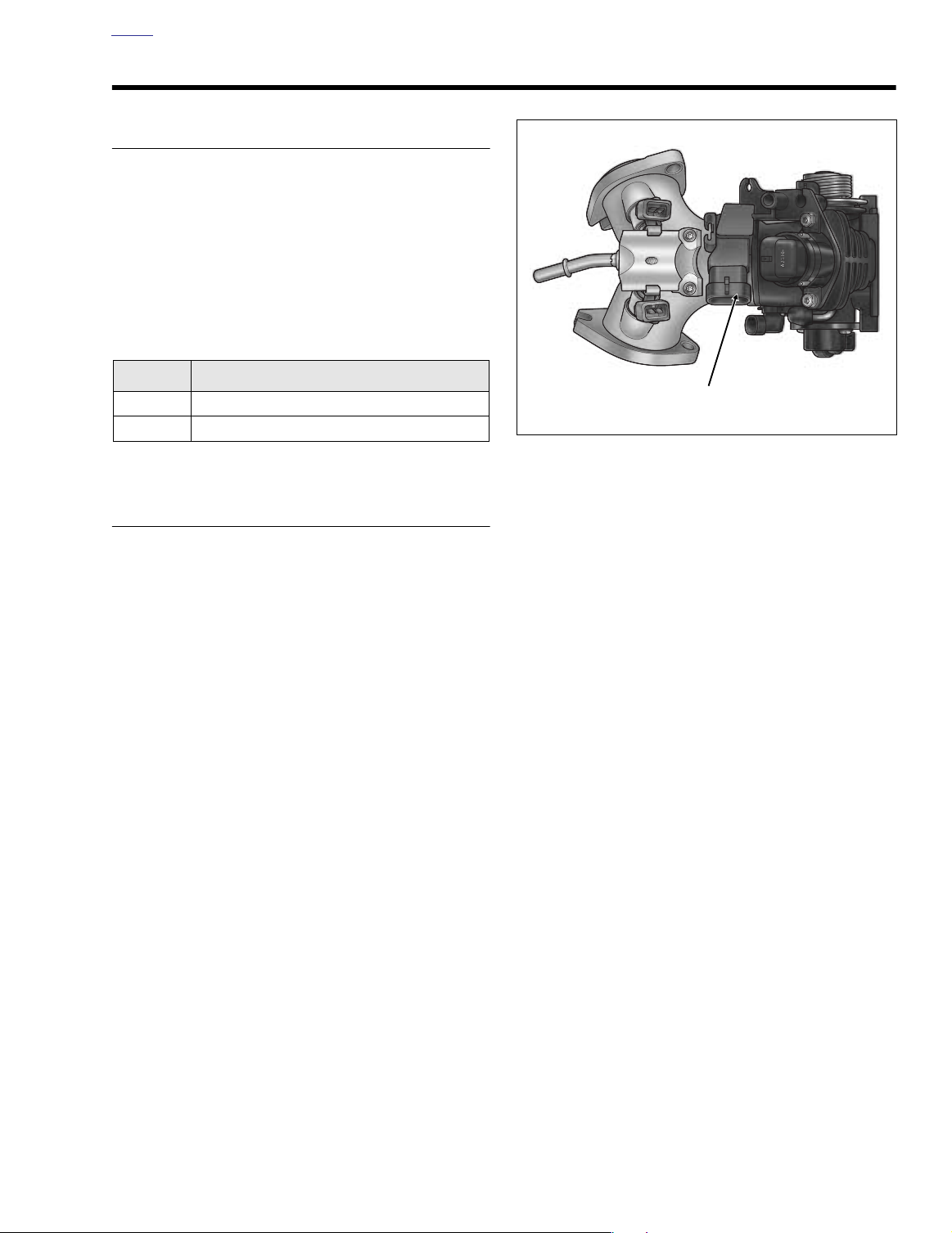
See Figure 5-45. The manifold absolute pressure sensor
(MAP sensor) is supplied 5 volts from the ECM (Pin 14) and
sends a signal back to the ECM (Pin 25). This signal varies in
accordance with engine vacuum and atmospheric barometric
pressure. Changes in barometric pressure are influenced by
weather and altitude.
Table 5-26. Code Description
DTC
P0107 MAP sensor open/low
P0108 MAP sensor high
DESCRIPTION
DIAGNOSTICS
Diagnostic Tips
●
These codes will set if the MAP sensor signal is out of
range. Code P0108 can only be detected with the engine
running.
MAP sensor output check. Using the VACUUM PUMP
●
(Part No. HD-23738), apply a vacuum to the pressure
port of the MAP sensor. The signal voltage should lower
as the vacuum is applied.
●
The MAP, TP and VSS sensors are connected to the
same reference line (+5V Vref). If the reference line goes
to ground or open, multiple codes will be set (DTC
P0107, P0108, P0122, P0123, P0501, P0502).
Figure 5-45. Induction Module (Top View)
Diagnostic Notes
The reference numbers below correlate with the circled numbers on the Test 5.19 flow charts.
1. Connect BREAKOUT BOX (Part No. HD-43876)
between wire harness and ECM. See Section 5.7 BREA-
KOUT BOX: EFI.
2. Use HARNESS CONNECTOR TEST KIT (Part No. HD-
41404), gray pin probes and patch cords.
2004 Touring: Engine Management (EFI) 5-69
Page 2
HOME
f1743q9s
MAP
Sensor
[80A]
[80B]
AB
A
BC
V/W
BK/W
To TP and
VSS sensors
C
R/W
R/W
To TP, ET &
IAT Sensors
V/W
BK/W
[78B]
[78A]
14 25 26
ECM
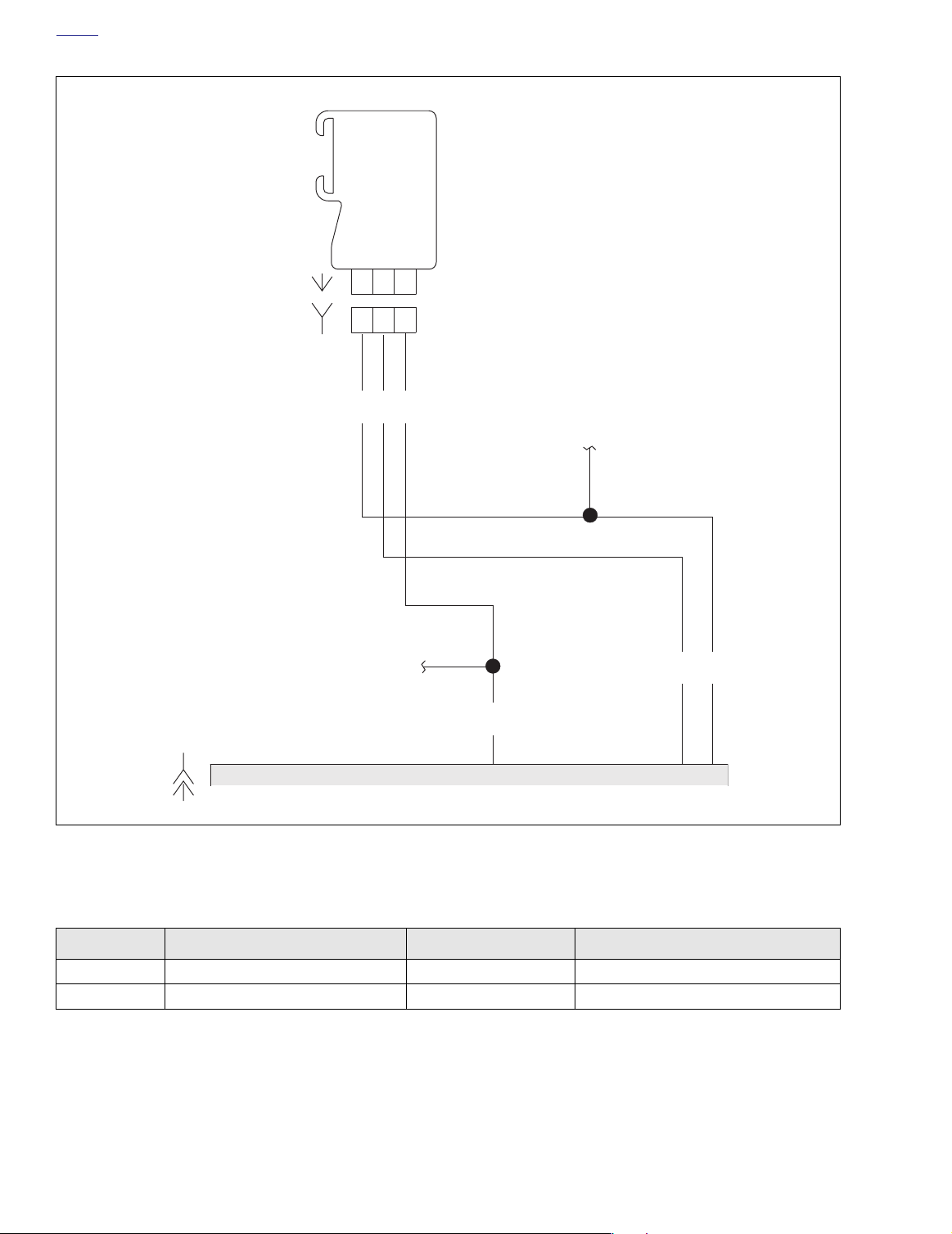
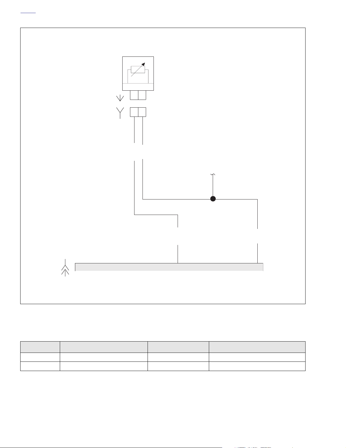
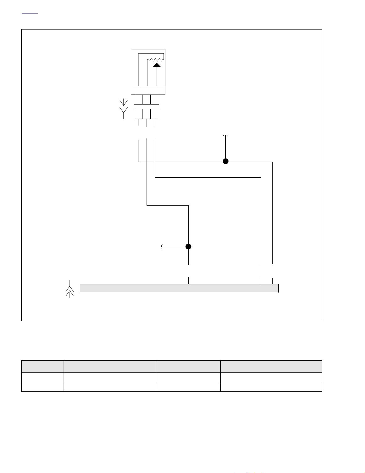
Figure 5-46. MAP Sensor Circuit
Table 5-27. Wire Harness Connectors in Figure 5-46.
NO.
[78] ECM 36-Place Packard Under Right Side Cover
[80] MAP Sensor 3-Place Packard Top of Induction Module
5-70 2004 Touring: Engine Management (EFI)
DESCRIPTION TYPE LOCATION
Page 3
HOME
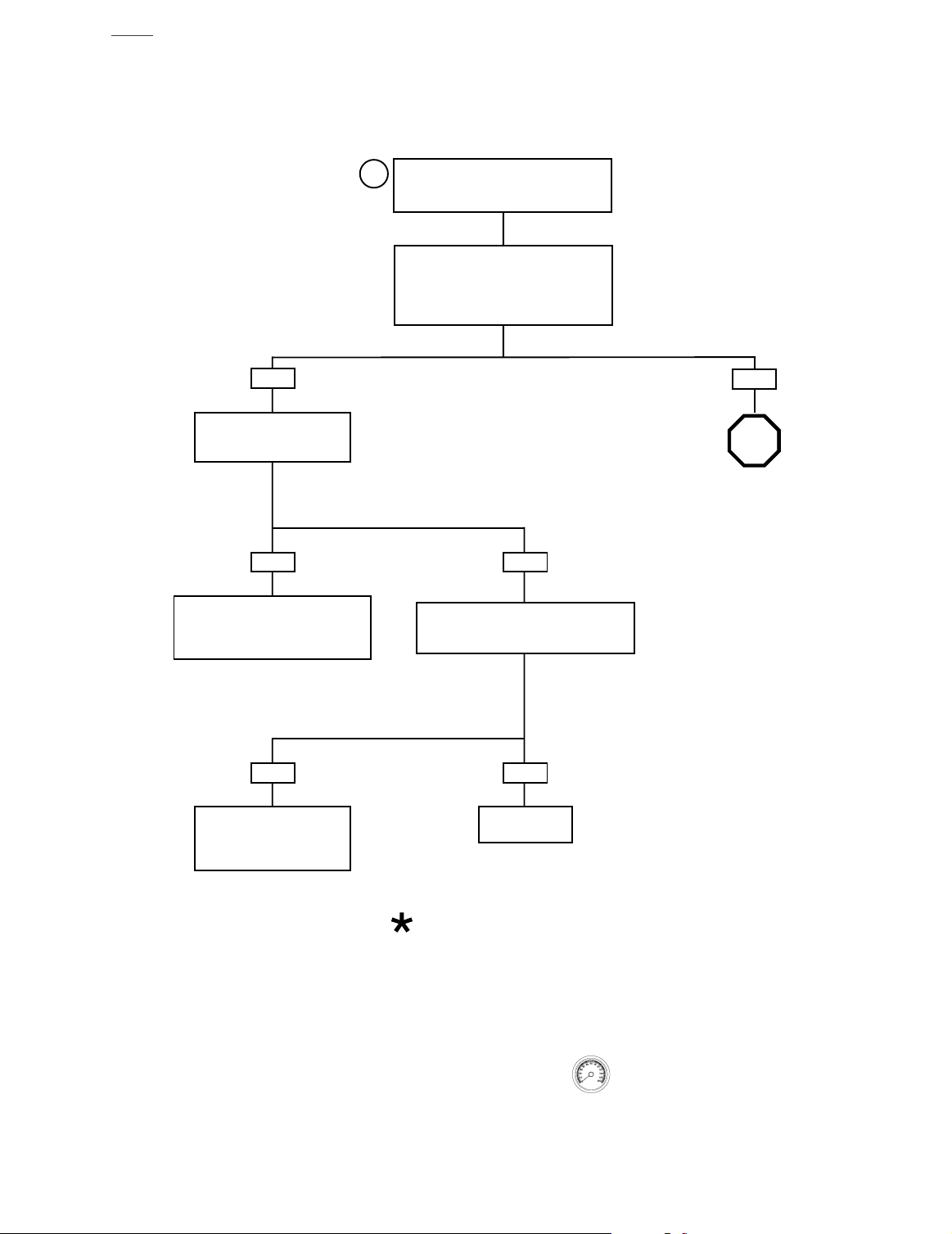
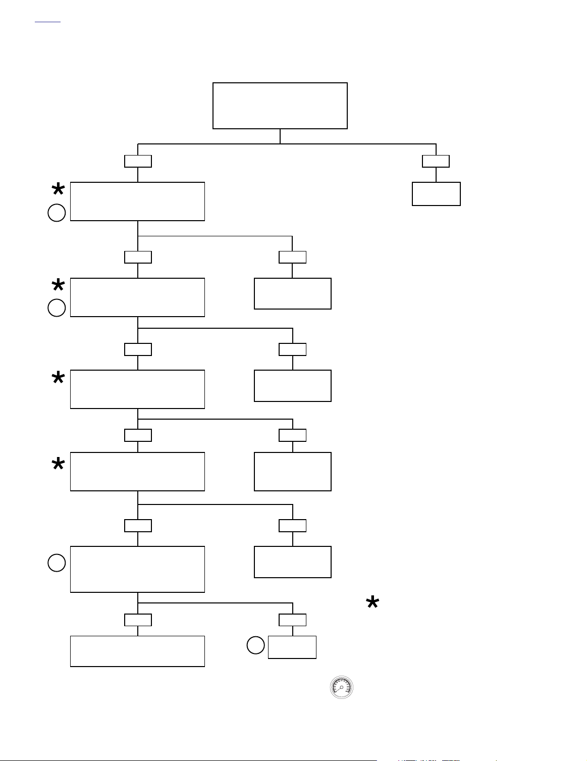
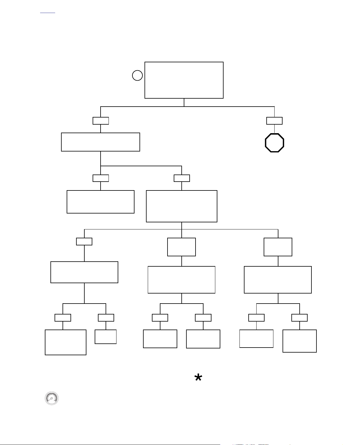
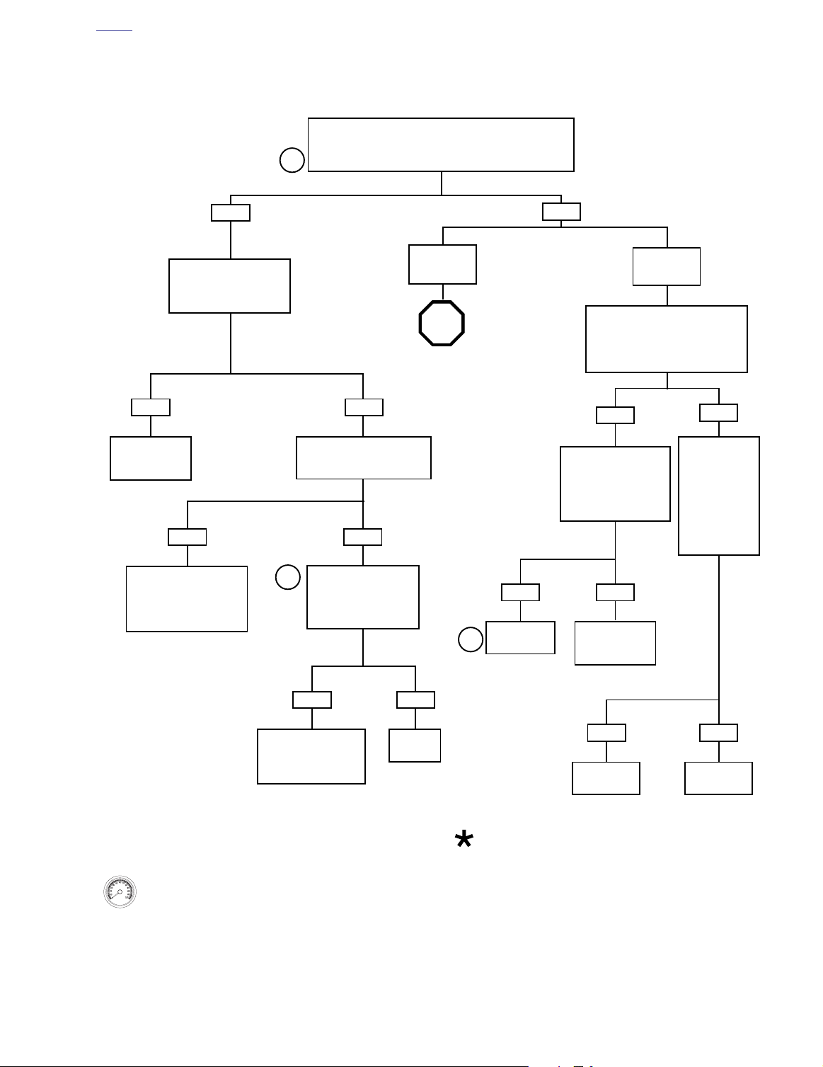
Test 5.19 (Part 1 of 2)
MAP SENSOR: DTC P0107, P0108
Connect Breakout Box. With ignition ON,
1
measure voltage between terminal 25
and terminal 26 on Breakout Box.
With key ON, engine OFF, voltage must be
between 3.5 and 5.0 volts.
With key ON, engine running, voltage must
be between 1.5-3.0 volts at hot idle.
Does voltage fit specifications?
YES
Perform 5.8 WIGGLE TEST
to check for intermittents.
Intermittents present?
YES
To identify the source of intermittents,
start with box marked by Bold Asterisk
under Test 5.19 (Part 2 of 2). Wiggle
harness while watching DVOM.
YES
Install original MAP sensor.
Replace ECM (reprogram,
relearn) and road test again
to verify.
NO
Replace MAP sensor. Clear codes and road
test. Did check engine lamp illuminate and
set DTC P0107 or P0108?
NO
System
now OK.
NO
STOP
Go to Test 5.19 (Part 2 of 2).
At some point in the flow chart you
may be instructed to jump directly
to a the box with the bold asterisk.
Disregard the asterisk (but not the
instruction box) if your normal progression through the chart brings
you to this location.
2004 Touring: Engine Management (EFI) 5-71
Clear codes using speedometer self diagnostics.
See 5.6 SPEEDOMETER SELF DIAGNOSTICS.
Confirm proper operation with no check engine
lamp.
Page 4
HOME
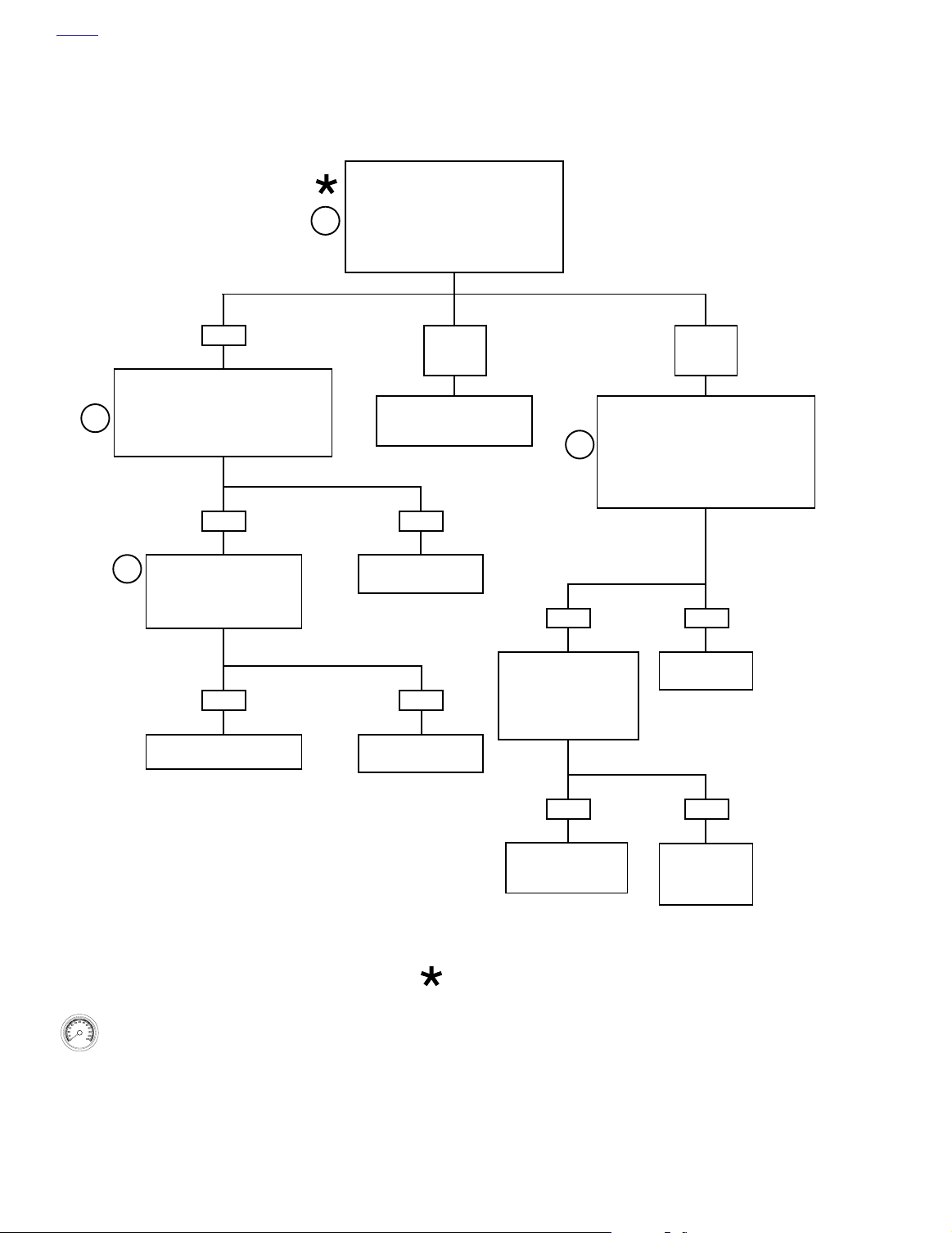
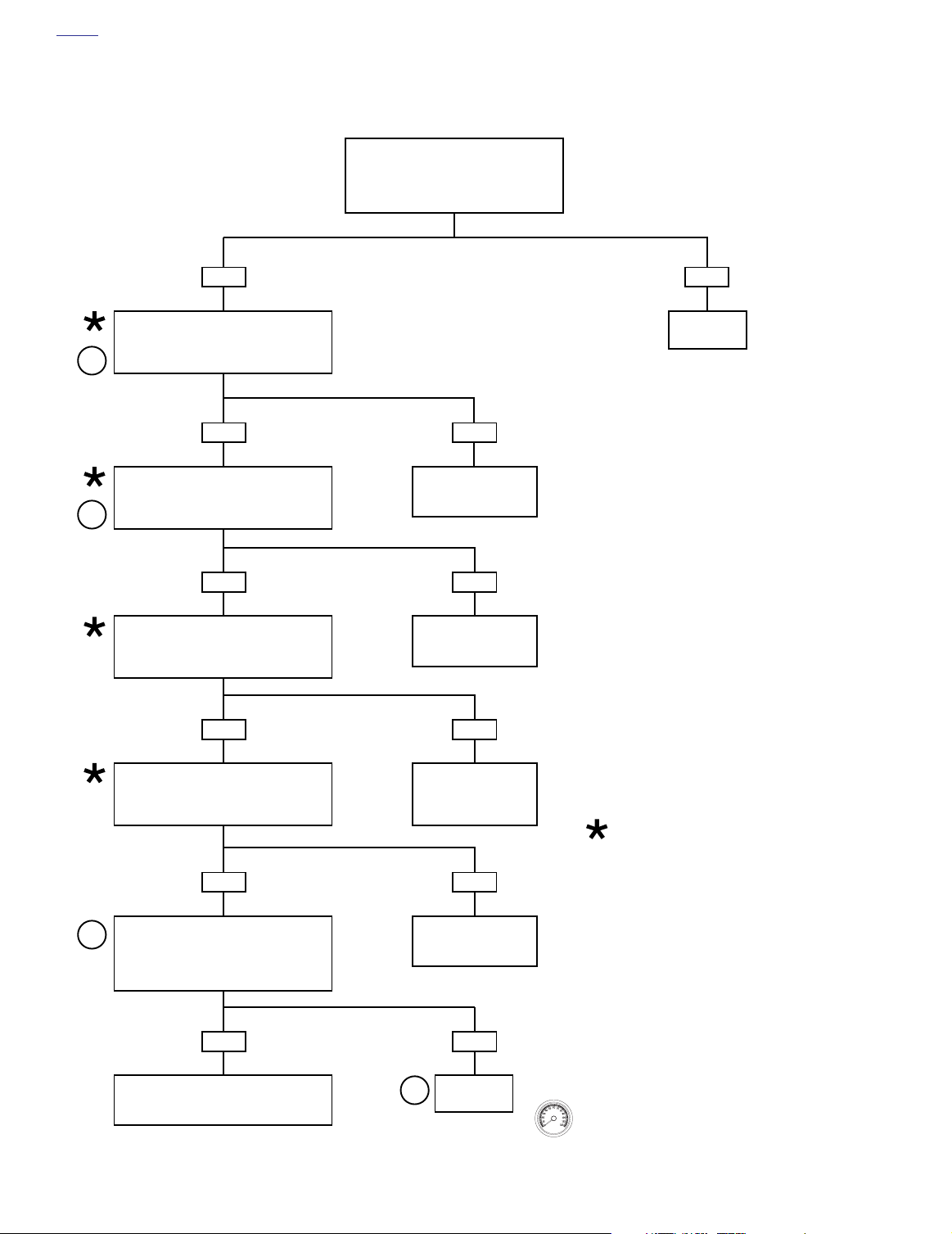
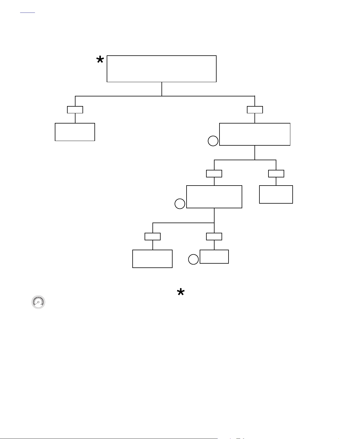
Test 5.19 (Part 2 of 2)
MAP SENSOR: DTC P0107, P0108
Continued from
Test 5.19 (Part 1 of 2).
Check the 5 volt reference supply at
the MAP sensor connector [80B]. With
2
ignition ON, measure voltage between
terminal C (R/W) and terminal A (BK/W).
Voltage approximately 5.0 volts?
YES
Connect Breakout Box to connector [78B]
leaving ECM disconnected.
OPEN CHECK: Measure resistance
2
between MAP connector [80B]
Terminal B and Breakout Box terminal 25.
Resistance less than 1 ohm?
YES
SHORT CHECK: Measure
2
resistance between MAP connector Terminal B and chassis
ground. Resistance greater
than 1 megohm?
YES
Replace MAP sensor. See
Touring Service Manual.
NO.
Greater
than 6V.
Locate short to 12 volts on R/W
wire in wire harness. Repair as
necessary.
NO
Locate and repair
open on V/W wire.
NO
Locate and repair
grounded V/W wire.
Connect Breakout Box to connector [78B]
Check continuity between MAP connector
[80B] Terminal C and Breakout Box
2
terminal 14. Then measure continuity
between MAP connector [80B] Terminal A
YES
Check resistance between
MAP connector [80B]
Terminal C and
Breakout Box terminal 26.
Resistance greater than
1 megohm?
YES
NO.
Less
than 4.5V.
leaving ECM disconnected.
and Breakout Box terminal 26.
Resistance less than 1 ohm?
NO
Repair
open wire.
NO
Clear codes using speedometer self diagnostics.
See 5.6 SPEEDOMETER SELF DIAGNOSTICS.
Confirm proper operation with no check engine
lamp.
5-72 2004 Touring: Engine Management (EFI)
Replace ECM.
Reprogram and learn
password.
At some point in the flow chart you
may be instructed to jump directly
to a the box with the bold asterisk.
Disregard the asterisk (but not the
instruction box) if your normal progression through the chart brings
you to this location.
Locate and repair
short between
R/W and BK/W
wires.
Page 5
HOME
DTC P0112, P0113 5.20
GENERAL
IAT Sensor
The ECM supplies and monitors a voltage signal (terminal 7)
to one side of the intake air temperature sensor (IAT sensor).
The other side of the IAT sensor is connected to a common
sensor ground, which is also connected to the ECM (terminal
26).
The IAT sensor is a thermistor device, meaning that at a spe-
cific temperature, it will have a specific resistance across its
terminals. As this resistance varies, so does the voltage on
(terminal 7).
At high temperatures, the resistance of the sensor is very
●
low, which effectively lowers the signal voltage on terminal 7.
●
At low temperatures, the resistance is very high, allowing
the voltage to rise close to 5 volts.
The ECM monitors this voltage to compensate for various
operating conditions.
Table 5-28. Code Description
DTC
P0112 IAT sensor voltage low
P0113 IAT sensor open/high
DESCRIPTION
DIAGNOSTICS
Diagnostic Tips
An intermittent may be caused by a poor connection, rubbed
through wire insulation or a wire broken inside the insulation.
Check the following conditions:
●
Poor connection:
[78] for backed out terminals, improper mating, broken
locks, improperly formed or damaged terminals, poor terminal-to-wire connection and damaged harness.
●
Perform
connections and harness check out OK, use a DVOM to
check the intake air temperature sensor voltage reading
while moving related connectors and wiring harness. If
the failure is induced, the intake air temperature sensor
voltage reading will change.
Shifted sensor:
●
used to test the intake air temperature sensor at various
temperature levels in order to evaluate the possibility of a
shifted (out-of-calibration) sensor which may result in
driveability problems.
All voltage and resistance values are approximate (±20%).
Measure IAT sensor resistance between ECM Terminal 7 and
system ground (ECM Terminal 26).
5.8 WIGGLE TEST
Inspect ECM and harness connector
to locate intermittents:
Refer to Tab le 5-29. This table may be
NOTE
If
Table 5-29. IAT Sensor Table
TEMP °C
-20 29121 4.9 -4
-10 16599 4.8 14
09750 4.6 32
10 5970 4.3 50
20 3747 4.0 68
25 3000 3.8 77
30 2417 3.6 86
40 1598 3.1 104
50 1080 2.6 122
60 746 2.2 140
70 526 1.7 158
80 377 1.4 176
90 275 1.1 194
100 204 0.9 212
RESISTANCE VOLTAGE TEMP °F
Diagnostic Notes
The reference numbers below correlate with the circled numbers on the Test 5.20 flow charts.
1. Connect BREAKOUT BOX (Part No. HD-43876) to EFI
wire harness
BREAKOUT BOX: EFI.
2. Use HARNESS CONNECTOR TEST KIT (Part No. HD-
41404), gray pin probes and patch cords.
3. Use HARNESS CONNECTOR TEST KIT (Part No. HD-
41404), gray socket probes and patch cords.
4. Replace IAT sensor. See Touring Service Manual.
only
(leave ECM disconnected). See 5.7
2004 Touring: Engine Management (EFI) 5-73
Page 6
HOME
f1743r9s
[89A]
IAT
Sensor
A
B
[78B]
[78A]
[89B]
A
Lt GN/Y
B
BK/W
To TP, ET &
MAP Sensors
Lt GN/Y
7 26
ECM
BK/W
Figure 5-47. IAT Sensor Circuit
Table 5-30. Wire Harness Connectors in Figure 5-47.
NO. DESCRIPTION TYPE LOCATION
[78] ECM 36-Place Packard Under Right Side Cover
[89] IAT Sensor 2-Place Packard Below Fuel Tank (Right Side)
5-74 2004 Touring: Engine Management (EFI)
Page 7

HOME
Test 5.20 (Part 1 of 2)
IAT SENSOR: DTC P0112, P0113
Connect Breakout Box to connector [78B] leaving
ECM disconnected. With engine at room temperature
(60-90° F or 16-32° C), use a DVOM to measure
1
resistance across terminals 7 and 26 on Breakout
Box. If engine is warm, refer to Tab le 5-29.
Resistance between 2.0k ohms and 5.0k ohms at
room temperature?
YES
Connect ECM to Breakout Box.
Perform 5.8 WIGGLE TEST to check for
intermittents. Intermittents present?
YES
While wiggling harness, perform
steps marked by BOLD ASTER-
ISKS under Test 5.20 (Part 2 of 2).
Repair as necessary.
YES
Replace IAT sensor, clear codes and
road test. Did check engine lamp illu-
minate and set DTC P0112 or
P0113?
NO
Disconnect IAT sensor connector [89].
Tu rn ignition ON. Using a DVOM, mea-
between ECM terminal 7 (positive) and
terminal 26 (negative) on Breakout Box.
1
disconnect ECM from breakout box.
Breakout Box terminal 7 and terminals
sure the voltage
Voltage approximately 5 volts?
NO.
Less than
4.7 volts.
With IAT sensor disconnected,
Measure resistance between
Resistance less than 1 megohm?
10 or 28.
NO
STOP
Go to Test 5.20 (Part 2 of 2).
NO.
Greater than
5.3 volts.
Unplug ECM leaving Breakout Box con-
1
nected at vehicle harness.
Measure voltage between
Breakout Box terminal 7 and terminals 10
or 28.
Voltage 0 volts?
YES
Install original IAT
sensor, replace ECM,
perform password
learning and road test.
Clear codes using speedometer self diagnostics.
See 5.6 SPEEDOMETER SELF DIAGNOSTICS.
Confirm proper operation with no check engine
lamp.
NO
System
OK.
YES
Repair short to
ground on
Lt GN/Y wire.
NO
Replace ECM.
Reprogram and
learn password.
2004 Touring: Engine Management (EFI) 5-75
YES
Replace ECM.
Reprogram and
learn password.
At some point in the flow chart you
may be instructed to jump directly
to a the box with the bold asterisk.
Disregard the asterisk (but not the
instruction box) if your normal progression through the chart brings
you to this location.
Examine IAT sig-
nal wire (Lt GN/Y)
for short to volt-
age and repair.
NO
Page 8
HOME
Test 5.20 (Part 2 of 2)
IAT SENSOR: DTC P0112, P0113
Continued from
Test 5.20 (Part 1 of 2).
Disconnect IAT sensor connector [89B] and
examine for damage. Connector OK?
YES
Using a DVOM, measure the resistance
between IAT sensor connector [89B]
Terminal A and ECM terminal 7 on Breakout
2
2
Box. Resistance less than 1.0 ohm?
YES
Using a DVOM, measure the resistance
between IAT sensor connector [89B]
Terminal B and ECM terminal 26 on Break-
out Box. Resistance less than 1.0 ohm?
YES
Using a DVOM, measure the resistance
between ECM terminal 7 and terminal 26 on
Breakout Box. Resistance greater
than 1.0 megohm?
YES
NO
Examine Lt GN/Y wire in
harness for open circuit
and repair.
NO
Examine BK/W wire in
harness for open circuit
and repair.
NO
NO
Repair
connector.
Using a DVOM, measure the resistance
between ECM terminal 7 on Breakout Box
and ground. Resistance greater
than 1.0 megohm?
YES
Remove IAT sensor and measure resistance
across the terminals of the IAT sensor
3
directly. Again, with sensor at room tempera-
ture 60-90° F or 16-32° C), is resistance
between 2.0k ohms and 5.0k ohms?
YES
Perform 5.8 WIGGLE TEST on steps
marked with a BOLD ASTERISK above to
locate intermittents. Repair as necessary.
5-76 2004 Touring: Engine Management (EFI)
Examine Lt GN/Y and
BK/W wires in harness
for short between these
two circuits and repair.
NO
Examine harness for
short to ground and
repair.
NO
Replace
4
IAT sensor.
At some point in the flow chart you
may be instructed to jump directly
to a the box with the bold asterisk.
Disregard the asterisk (but not the
instruction box) if your normal progression through the chart brings
you to this location.
Clear codes using speedometer self diagnostics.
See 5.6 SPEEDOMETER SELF DIAGNOSTICS.
Confirm proper operation with no check engine
lamp.
Page 9
HOME
DTC P0117, P0118 5.21
GENERAL
ET Sensor
The ECM supplies and monitors a voltage signal (terminal 6)
to one side of the engine temperature sensor (ET sensor).
The other side of the ET sensor is connected to a common
sensor ground (terminal 26) of the ECM.
The ET sensor is a thermistor device, which means that at a
specific temperature it will have a specific resistance across
its terminals. As this resistance varies, so does the voltage
(terminal 6).
At high temperatures, the resistance of the sensor is very
●
low, which effectively lowers the signal voltage on terminal 6.
●
At low temperatures, the resistance is very high, allowing
the voltage to rise close to 5 volts.
The ECM monitors this voltage to compensate for various
operating conditions. The ECM also uses the sensor input as
a reference for determining IAC pintle position.
Table 5-31. Code Description
DTC
P0117 ET sensor voltage low
P0118 ET sensor open/high
DESCRIPTION
DIAGNOSTICS
Diagnostic Tips
Once the engine is started, the ET voltage should rise
●
steadily.
●
An intermittent may be caused by a poor connection,
rubbed through wire insulation or a wire broken inside
the insulation.
Check the following conditions:
Poor connection:
●
[78] for backed out terminals, improper mating, broken
locks, improperly formed or damaged terminals, poor terminal-to-wire connection and damaged harness.
Perform
●
connections and harness check out OK, use a DVOM to
check the engine temperature sensor voltage reading
while moving related connectors and wiring harness. If
the failure is induced, the engine temperature sensor
voltage reading will change.
Shifted sensor:
●
used to test the engine temperature sensor at various
temperature levels in order to evaluate the possibility of a
shifted (out-of-calibration) sensor which may result in
driveability problems.
5.8 WIGGLE TEST
Inspect ECM and harness connector
to locate intermittents:
Refer to Tab le 5-32. This table may be
If
Table 5-32. ET Sensor Table
TEMP °C
-20 28144 4.4 -4
-10 15873 4.0 14
09255 3.5 32
10 5571 3.0 50
20 3457 2.4 68
25 2750 2.1 77
30 2205 1.8 86
40 1442 1.3 or 4.1
50 965 1.0 or 3.7
60 661 3.3 140
70 462 2.9 158
80 329 2.5 176
90 238 2.1 194
100 175 1.7 212
*
Between 40-50°C the ECM changes scaling. Voltages for ECT
sensor will shift scales in that range. This provides proper sensor resolution for all temperatures.
RESISTANCE VOLTAGE TEMP °F
*
*
104
122
NOTE
All voltage and resistance values are approximate (±20%).
Measure ET sensor resistance between ECM Terminal 6 and
system ground (ECM Terminal 26).
Diagnostic Notes
The reference numbers below correlate with the circled numbers on the Test 5.21 flow charts.
1. Connect BREAKOUT BOX (Part No. HD-43876) to EFI
wire harness
BREAKOUT BOX: EFI.
2. Use HARNESS CONNECTOR TEST KIT (Part No. HD-
41404), gray pin probes and patch cords.
3. Use HARNESS CONNECTOR TEST KIT (Part No. HD-
41404), gray socket probes and patch cords.
4. Replace ET sensor. See Touring Service Manual.
only
(leave ECM disconnected). See 5.7
2004 Touring: Engine Management (EFI) 5-77
Page 10

HOME
f1743s9s
ET
Sensor
[90A]
[90B]
AB
A
B
PK/Y
BK/W
PK/Y
To TP, IAT &
MAP Sensors
BK/W
[78B]
[78A]
ECM
6 26
Figure 5-48. ET Sensor Circuit
Table 5-33. Wire Harness Connectors in Figure 5-48.
NO.
[78] ECM 36-Place Packard Under Right Side Cover
[90] ET Sensor 2-Place Packard Back of Front Cylinder (Left Side)
5-78 2004 Touring: Engine Management (EFI)
DESCRIPTION TYPE LOCATION
Page 11
HOME
Test 5.21 (Part 1 of 2)
ET SENSOR: DTC P0117, P0118
Connect Breakout Box to connector [78B]
leaving ECM disconnected. With engine at
room temperature (60-90° F or 16-32° C),
1
use a DVOM to measure resistance across
terminals 6 and 26 on Breakout Box. If
engine is warm, refer to Table 5-32. Resistance between 2.0k ohms and 5.0k ohms?
YES
Connect ECM to Breakout Box.
Perform 5.8 WIGGLE TEST to check for
intermittents. Intermittents present?
YES
While wiggling harness, perform
steps marked by BOLD ASTER-
ISKS under Test 5.21 (Part 2 of 2).
Repair as necessary.
YES
Replace ET sensor, clear codes and
road test. Did check engine lamp illu-
minate and set DTC P0117 or
P0118?
NO
Disconnect ET sensor connector [90].
Turn ignition ON. Using a DVOM, mea-
sure the voltage between
terminal 6 (positive) and
terminal 26 (negative) on Breakout Box.
Voltage approximately 5 volts?
NO.
Less than
4.7 volts.
With ET sensor disconnected,
disconnect ECM connector [78B].
Measure resistance between
terminal 6 and terminals 10 or 28.
Resistance less than 1 megohm?
NO
STOP
Go to Test 5.21 (Part 2 of 2).
NO.
Greater than
5.3 volts.
Unplug ECM leaving Breakout Box
connected at vehicle harness.
Measure voltage between
terminal 6 and terminals 10 or 28.
Voltage 0 volts?
YES
Install original
ET sensor,
replace ECM, perform
password learning
and road test.
Clear codes using speedometer self diagnostics.
See 5.6 SPEEDOMETER SELF DIAGNOSTICS.
Confirm proper operation with no check engine
lamp.
NO
System
OK.
YES
Repair short to
ground on
PK/Y wire.
NO
Replace ECM.
Reprogram and
learn password.
At some point in the flow chart you
may be instructed to jump directly
to a the box with the bold asterisk.
Disregard the asterisk (but not the
instruction box) if your normal progression through the chart brings
you to this location.
2004 Touring: Engine Management (EFI) 5-79
YES
Replace ECM.
Reprogram and
learn password.
NO
Examine ET sig-
nal wire (PK/Y) for
short to voltage
and repair.
Page 12
HOME
Test 5.21 (Part 2 of 2)
ET SENSOR: DTC P0117, P0118
Continued from
Test 5.21 (Part 1 of 2).
Disconnect ET sensor connector [90B] and
examine for damage. Connector OK?
YES
Using a DVOM, measure the resistance
between ET sensor connector [90B]
Terminal A and ECM terminal 6 on Breakout
2
2
Box. Resistance less than 1.0 ohm?
YES
Using a DVOM, measure the resistance
between ET sensor connector [90B]
Terminal B and ECM terminal 26 on Break-
out Box. Resistance less than 1.0 ohm?
YES
Using a DVOM, measure the resistance
between ECM terminal 6 and terminal 26 on
Breakout Box. Resistance greater
than 1.0 megohm?
YES
NO
Examine PK/Y wire in
harness for open circuit
and repair.
NO
Examine BK/W wire in
harness for open circuit
and repair.
NO
NO
Repair
connector.
Using a DVOM, measure the resistance
between ECM terminal 6 on Breakout Box
and ground. Resistance greater
than 1.0 megohm?
YES
Remove ET sensor and measure resistance
3
across the terminals of the ET sensor
directly. Again, with sensor at room tempera-
ture (60-90° F or 16-32° C), is resistance
between 2.0k ohms and 5.0k ohms?
YES
Perform 5.8 WIGGLE TEST on steps
marked with a BOLD ASTERISK above to
locate intermittents. Repair as necessary.
5-80 2004 Touring: Engine Management (EFI)
Examine PK/Y and
BK/W wires in harness
for short between these
two circuits and repair.
NO
Examine harness for
short to ground and
repair.
NO
Replace
4
ET sensor.
At some point in the flow chart
you may be instructed to jump
directly to a the box with the bold
asterisk. Disregard the asterisk
(but not the instruction box) if your
normal progression through the
chart brings you to this location.
Clear codes using speedometer self diagnostics.
See 5.6 SPEEDOMETER SELF DIAGNOSTICS.
Confirm proper operation with no check engine
lamp.
Page 13
HOME
DTC P0122, P0123 5.22
GENERAL
TP Sensor
The ECM supplies a 5 volt signal (terminal 14) to the throttle
position sensor (TP sensor). The TP sensor sends a signal
back to the ECM (terminal 24). The returned signal varies in
voltage according to throttle position.
At idle (closed throttle), the signal is typically in the range
●
of 0.20-0.80 volts.
●
At wide open throttle, the signal is normally 4.0-4.9 volts.
A code P0122 or P0123 will set if the TP sensor voltage signal does not fall within the acceptable range.
Check TP sensor voltage reading with DVOM. If TP sen-
●
sor is equal to or greater than 3.8 volts then the system is
in “clear flood” mode and engine will not start. While
spark is present, fuel is shut off. Problem can be
mechanical, such as stuck throttle cables.
Table 5-34. Code Description
DTC
P0122 TP sensor open/low
P0123 TP sensor high
DESCRIPTION
DIAGNOSTICS
Check for the following conditions:
Poor Connection:
●
[78B] for backed out terminals, improper mating, broken
locks, improperly formed or damaged terminals, poor terminal-to-wire connection and damaged harness.
●
Perform
connections and harness check out OK, monitor TP sensor voltage using a DVOM while moving related connectors and wiring harness. If the failure is induced, the TP
sensor voltage reading will change.
●
TP sensor scaling:
play while opening the throttle with engine stopped and
ignition key ON. Display should vary from closed throttle
TP sensor voltage (when throttle is closed) to greater
than 4.0 volts (when throttle is held wide open). As the
throttle is
gradually without spikes or low voltages being observed.
5.8 WIGGLE TEST
Inspect ECM and harness connector
to locate intermittents:
Observe the TP sensor voltage dis-
slowly
moved, the voltage should change
If
Diagnostic Notes
The reference numbers below correlate with the circled numbers on the Test 5.22 flow charts.
1. Connect a BREAKOUT BOX (Part No. HD-43876)
between EFI wire harness and ECM before measuring
voltage. See 5.7 BREAKOUT BOX: EFI. If using a DVOM
to measure voltage, take reading across terminal 24
(positive lead) and terminal 26 (negative lead) on Breakout Box.
2. Replace TP sensor. See Touring Service Manual.
Diagnostic Tips
The DVOM reads throttle position in volts. Voltage should
increase at a steady rate as the throttle is moved from idle to
wide open. A short to ground or open on the GY/V or R/W
wires also will result in a DTC P0122. A short to ground or
open on the R/W wire (+5v REF) sets multiple codes as
described below.
NOTE
The MAP, TP and VSS sensors are connected to the same
reference line (+5V Vref). If the reference line goes to ground
or open, multiple codes will be set (DTC P0107, P0108,
P0122, P0123, P0501, P0502). Start with the trouble code
having the lowest ranking value.
3. Use HARNESS CONNECTOR TEST KIT (Part No. HD-
41404), gray pin probes and patch cords.
2004 Touring: Engine Management (EFI) 5-81
Page 14
HOME
s0452x9x
TP
sensor
[88A]
[88B]
ABC
A
BC
R/W
BK/W
To MAP
sensor
GY/V
R/W
To MAP, ET &
IAT sensors
GY/V
BK/W
[78B]
[78A]
14 24 26
ECM
Figure 5-49. TP Sensor Circuit
Table 5-35. Wire Harness Connectors in Figure 5-49.
NO. DESCRIPTION TYPE LOCATION
[78] ECM 36-Place Packard Under Right Side Cover
[88] TP Sensor 3-Place Packard Below Fuel Tank (Right Side)
5-82 2004 Touring: Engine Management (EFI)
Page 15
HOME
Test 5.22 (Part 1 of 2)
TP SENSOR: DTC P0122, P0123
With ignition key ON, measure TP sensor voltage while gradu-
ally opening throttle. Does voltage increase steadily
with no spikes or low voltages from 0.2-0.8 volts at idle
1
(closed throttle) to 4.0-4.9 volts at wide open throttle?
Check engine lamp ON
continuously and
DTC P0122 or P0123
the only one set?
YES
YES
Replace ECM.
Reprogram and
learn password.
YES NO
While wiggling harness,
start with the first step of
Test 5.22 (Part 2 of 2)
(marked by BOLD ASTER-
ISK). Repair as necessary.
YES
NO
Perform 5.8 WIGGLE TEST
to check for intermittents.
Intermittents present?
Replace TP sensor, clear
2
codes and road test.
Did check engine lamp
illuminate and set DTC
P0122 or P0123?
Voltage is
greater than
4.95 volts.
STOP
Go to Test 5.22 (Part 2 of 2).
2
YES
Replace
TP sensor.
NO
Low voltage
observed.
Unplug TP sensor connector [88B]
and measure voltage between
Terminal B (+) and Terminal A (-)
with ignition ON.
Is reading 4.8-5.0 volts?
YES
Disconnect ECM from
Breakout Box. Check
resistance between ECM
terminal 24 on Breakout
Box to chassis ground.
Greater than 1 megohm?
NO
Find short to
ground on GY/V
signal wire.
or spikes
NO
Measure
resistance
between
TP sensor
connector [88B]
Terminal B to
ECM terminal 14
on Breakout Box.
Less than
1.0 ohm?
YES
Install original
TP sensor, replace ECM
(reprogram and learn
password) and road test.
Clear codes using speedometer self diagnostics.
See 5.6 SPEEDOMETER SELF DIAGNOSTICS.
Confirm proper operation with no check engine
lamp.
NO
System
OK.
YES
Repair open
in BK/W wire.
At some point in the flow chart you
may be instructed to jump directly
to a the box with the bold asterisk.
Disregard the asterisk (but not the
instruction box) if your normal progression through the chart brings
you to this location.
NO
Repair open
in R/W wire.
2004 Touring: Engine Management (EFI) 5-83
Page 16
HOME
Test 5.22 (Part 2 of 2)
TP SENSOR: DTC P0122, P0123
YES NO
Continued from Test 5.22 (Part 1 of 2).
With ignition key OFF, disconnect ECM connector [78B]. Turn
ignition key ON. Voltage greater than 0 volts across terminal 24
and terminal 26 on Breakout Box?
Repair short
between GY/V signal
wire and 12 volts.
Clear codes using speedometer self diagnostics.
See 5.6 SPEEDOMETER SELF DIAGNOSTICS.
Confirm proper operation with no check engine
lamp.
YES
Repair short
between R/W and
GY/V signal wire.
ECM terminal 24 on Breakout Box and
TP sensor connector [88B] Terminal C.
3
YES
Measure resistance from TP
sensor connector [88B]
Terminal C to Terminal B.
Less than 1.0 megohm?
3
NO
Replace
TP sensor.
2
At some point in the flow chart you
may be instructed to jump directly
to a the box with the bold asterisk.
Disregard the asterisk (but not the
instruction box) if your normal progression through the chart brings
you to this location.
Measure resistance between
Less than 0.5 ohm?
NO
Repair open
GY/V
signal wire.
5-84 2004 Touring: Engine Management (EFI)
Page 17

HOME
s0472x9x
HD34730-2C
DTC P0261, P0262, P0263, P0264 5.23
GENERAL
Fuel Injectors
The fuel injectors are solenoids that allow pressurized fuel
into the intake tract. The injectors are timed to the engine
cycle and triggered sequentially. The power for the injectors
comes from the system relay. The system relay also provides
power for the fuel pump and the ignition coil. The ECM provides the path to ground to trigger the injectors.
NOTE
ECM fuse and system relay failures or wiring harness problems will cause 12 volt power to be lost to both injectors, ignition coils and fuel pump.
Table 5-36. Code Description
Figure 5-50. Fuel Injector Connector
DTC
P0261 Front injector open/low
P0262 Front injector high
P0263 Rear injector open/low
P0264 Rear injector high
DESCRIPTION
DIAGNOSTICS
Diagnostic Notes
The reference numbers below correlate with the circled numbers on the Test 5.23 flow charts.
1. See Touring Service Manual for all service information.
2. Use HARNESS CONNECTOR TEST KIT (Part No. HD-
41404), purple pin probe and patch cord.
3. Connect a BREAKOUT BOX (Part No. HD-43876)
between EFI wire harness and ECM. See 5.7 BREAK-
OUT BOX: EFI.
Figure 5-51. Fuel Injector Test Lamp
(Part No. HD-34730-2C)
2004 Touring: Engine Management (EFI) 5-85
Page 18

HOME
f2208h8x
System relay
Power gnd.
Switch power
ECM
Power gnd.
Constant power
Coil R
Inj. R
Inj. F
Ion sense
Coil F
[78A] [78B]
1
1
2
2
3
3
4
4
5
5
6
6
7
7
8
8
9
9
10 11 12
10 11 12
13 14 15 16 17 18 19 20 21 22 23 24 25 26 27 28 29 30 31 32 33 34 35 36
13 14 15 16 17 18 19 20 21 22 23 24 25 26 27 28 29 30 31 32 33 34 35 36
GN/O
GN/GY
Y/BE
W/Y
BE/GY
BE/O
W/BK
W/Y
AB
[84B] [84A]
AB
[85B] [85A]
ECM fuse
GY/BE
BK
W/BK
[8B] [8A]
AB
AB
15 amp
R
12
12
11
11
10
10
9
9
8
8
7
7
6
6
5
5
4
4
3
3
2
2
1
1
Y/GN
Y/GN
GY/BE
Y/BE
BE/O
W/BK
BK
BE/GY
IGN fuse
W/BK
R
15 amp
GY
10
12
11
10
12
11
Y/GN
[83B] [83A]
R/BK
DCBA
9
9
15 amp
fuel pump
fuse
AB CD
AB CD
R
[33B]
[33A]
Ignition
switch
12345
678
12345
678
[62B]
Y/GN
BE/GY
GN/O
W/BK
[13A] [13B]
123
123
BK
Ignition
coil
40 Amp
Maxi Fuse
[1B]
[1A]
System relay
87
IQCPR
87A
30 85 86
Fuel pump
123
O/GY
[141B][141A]
Battery
123
–+
BK
BK
BK
BK
10
12
11
9
10
12
11
9
12345
678
678
[22A]
[22B]
12345
Engine stop
switch
Figure 5-52. Battery Voltage Circuit (FLTR, FLHT/C/U)
Table 5-37. Wire Harness Connectors in Figure 5-52.
NO.
[1] Main to Interconnect Harness 12-Place Deutsch (Black) Inner Fairing (Right Fairing Bracket)
[8] Main to EFI Harness 12-Place Deutsch (Gray) Under Right Side Cover
[22] Right Handlebar Switches 12-Place Deutsch (Black) Inner Fairing (Right Fairing Support Brace)
[33] Ignition/Light Key Switch 4-Place Packard Inner Fairing (Top Fork Bracket)
[78] ECM 36-Place Packard Under Right Side Cover
[83] Ignition Coil 4-Place Packard Below Fuel Tank (Left Side)
[84] Front Injector 2-Place Packard Below Fuel Tank (Left Side)
[85] Rear Injector 2-Place Packard Below Fuel Tank (Left Side)
5-86 2004 Touring: Engine Management (EFI)
DESCRIPTION TYPE LOCATION
Page 19

HOME
f2208m8x
System relay
Power gnd.
Switch power
ECM
Ion sense
Power gnd.
Constant power
Coil R
Inj. R
Inj. F
Coil F
[78A] [78B]
1
1
2
2
3
3
4
4
5
5
6
6
7
7
8
8
9
9
10 11 12
10 11 12
13 14 15 16 17 18 19 20 21 22 23 24 25 26 27 28 29 30 31 32 33 34 35 36
13 14 15 16 17 18 19 20 21 22 23 24 25 26 27 28 29 30 31 32 33 34 35 36
GN/O
GN/GY
Y/BE
W/Y
BE/GY
BE/O
W/BK
W/Y
BK
BK
AB
[84B] [84A]
AB
[85B] [85A]
15 amp
ECM fuse
GY/BE
BK
W/BK
[8B] [8A]
AB
AB
12
11
10
9
8
7
6
5
4
3
2
1
[62B]
Y/GN
BE/GY
System relay
[62B]
87
IQCPR
87A
30 85 86
GN/O
W/BK
Fuel pump
123
Y/GN
15 amp
fuel pump
fuse
Y/GN
Y/GN
BK
123
[141B][141A]
Y/GN
AB CD
AB CD
GY/BE
Y/BE
Ignition
coil
BE/O
W/BK
[83B] [83A]
BE/GY
–+
Battery
R
12
BK
11
10
9
8
7
6
5
4
3
2
1
W/BK
BK
R
R/BK
15 amp
IGN fuse
10
12
11
10
12
11
12-Place on
FLHP Only
GY
9
9
I B A
R
678
678
40 Amp
Maxi Fuse
[33B]
[33A]
Ignition
switch
12345
[22A]
[22B]
12345
Engine stop
switch
BK
Figure 5-53. Battery Voltage Circuit (FLHR/C/S)
Table 5-38. Wire Harness Connectors in Figure 5-53.
NO.
[8] Main to EFI Harness 12-Place Deutsch (Gray) Under Right Side Cover
[22] Right Handlebar Switches 12-Place Deutsch (Black) Inside Headlamp Nacelle
[33] Ignition/Light Key Switch 3-Place Packard Under Console
[78] ECM 36-Place Packard Under Right Side Cover
[83] Ignition Coil 4-Place Packard Below Fuel Tank (Left Side)
[84] Front Injector 2-Place Packard Below Fuel Tank (Left Side)
[85] Rear Injector 2-Place Packard Below Fuel Tank (Left Side)
DESCRIPTION TYPE LOCATION
2004 Touring: Engine Management (EFI) 5-87
Page 20

HOME
Test 5.23 (Part 1 of 3)
FUEL INJECTORS: DTC P0261, P0262, P0263, P0264
Is wire bail on connector securely
1
YES NO
attached to the fuel injector?
See Figure 5-51. Using Fuel
Injector Test Lamp, crank
engine. Does lamp flash?
YES NO
Recheck connections.
Perform 5.8 WIGGLE TEST
to check for intermittents.
Intermittents present?
YES NO
Repair
intermittent.
YES NO
Measure resistance of
suspect injector across
2
injector terminals.
Resistance
10.0-25.0 ohms?
2
YES NO
STOP
Go to Test 5.23 (Part 2 of 3).
YES NO
Reconnect.
Check Terminal A (Y/GN wire)
on injector connector to ground.
Voltage equivalent to
battery voltage for 2 seconds
after key ON?
Check for 12 volts at terminal 87 of sys-
tem relay during first 2 seconds after
key ON. Correct voltage present?
Check for loose
or corroded terminals
in harness.
Clear codes using speedometer self diagnostics.
See 5.6 SPEEDOMETER SELF DIAGNOSTICS.
Confirm proper operation with no check engine
lamp.
1
5-88 2004 Touring: Engine Management (EFI)
Replace
injector.
YES NO
Perform 5.8 WIGGLE TEST
to check for intermittents.
Repair as necessary.
System relay OK. Measure
resistance between terminal 87 of
system relay and Terminal A
(Y/GN wire) at injector connector.
Resistance less than 0.5 ohm?
Find and repair
bad connection
or open wire.
STOP
Go to Test 5.23
(Part 3 of 3).
Page 21

HOME
Test 5.23 (Part 2 of 3)
FUEL INJECTORS: DTC P0261, P0262, P0263, P0264
2
3
FRONT INJECTOR: DTC P0261 or P0262.
Measure resistance between Breakout Box terminal 21
(W/Y wire) and Terminal B of front injector connector
Check for continuity between terminal
Front injector codes: Check continuity
between terminal 21 and terminal 10.
Rear injector codes: Check continu-
ity between terminal 19 and terminal
10 and ground.
Continuity present?
[84B].
YES
or
10.
YES
Resistance
less than 0.5 ohm?
Repair open
REAR INJECTOR: DTC P0263 or P0264.
Measure resistance between Breakout Box terminal 19
(GN/GY wire) and Terminal B of rear injector connector
NO
NO
[85B].
NO
Repair open or
poor connection.
2
3
Repair short
to ground.
Clear codes using speedometer self diagnostics.
See 5.6 SPEEDOMETER SELF DIAGNOSTICS.
Confirm proper operation with no check engine
lamp.
Check for voltage with key on.
Front injector codes: Check
Breakout Box terminal 21.
Rear injector codes: Check
Breakout Box terminal 19.
Voltage present after 2 seconds?
YES
Repair short
to voltage.
NO
Replace ECM. Reprogram
and learn password.
2004 Touring: Engine Management (EFI) 5-89
Page 22

HOME
Test 5.23 (Part 3 of 3)
FUEL INJECTORS: DTC P0261, P0262, P0263, P0264
Continued from Test 5.23 (Part 1 of 3).
Check for 12 volts at terminal 30 of the system relay.
Correct voltage present?
Check for 12 volts at terminal 86
3
of the system relay.
Correct voltage present?
Measure resistance between
terminal 86 of the system
relay and ECM terminal 13 on
Breakout Box.
Resistance less than 0.5 ohm?
Measure resistance between
terminal 85 of the system relay
and ECM terminal 4 on Break-
Resistance less than 0.5 ohm?
out Box.
YES
YES
YES
NO
Find and repair open on
BE/GY wire between
fuse and relay.
NO
See 5.11 NO ECM
POWER.
NO
Find and repair
open on W/BK
wire.
Clear codes using speedometer self diagnostics.
See 5.6 SPEEDOMETER SELF DIAGNOSTICS.
Confirm proper operation with no check engine
lamp.
5-90 2004 Touring: Engine Management (EFI)
YES
Install known good relay.
Does fuel pump run for first
2 seconds after key ON?
YES
Replace
relay
NO
Find and repair
open on GN/O
wire.
NO
Reinstall original relay.
Replace ECM. Reprogram
and learn password.
Page 23

HOME
f2217x8x
Socket Screw
f2256x8x
Crankshaft
Position Sensor
Connector [79]
Under Voltage Regulator
DTC P0373, P0374 5.24
GENERAL
CKP Sensor
If the crank position sensor (CKP sensor) signal is weak or
absent, diagnostic trouble codes P0373 or P0374 will be set.
NOTE
If signal is not detected or cannot synchronize (DTC P0374),
engine will not start.
Table 5-39. Code Description
DTC
P0373 CKP sensor intermittent
P0374 CKP sensor synch error
DESCRIPTION
DIAGNOSTICS
Diagnostic Tips
Engine must be cranked for more than five seconds with-
●
out CKP signal to set code.
Diagnostic Notes
The reference numbers below correlate with the circled numbers on the Test 5.24 flow chart.
1. Connect BREAKOUT BOX (Part No. HD-43876) to ECM
wire harness
BREAKOUT BOX: EFI.
2. One megohm is very high resistance. Some meters will
read ∞, OL, etc.
3. Use HARNESS CONNECTOR TEST KIT (Part No. HD-
41404), brown socket probes and patch cords.
4. For testing purposes, install sensor without running wiring along normal path. Disconnect and route wiring properly if system is now OK.
only
(leave ECM disconnected). See 5.7
Figure 5-54. Crankshaft Position Sensor
Figure 5-55. Voltage Regulator (Left Side View)
2004 Touring: Engine Management (EFI) 5-91
Page 24

HOME
s0453x9x
CKP
sensor
[78B]
[78A]
[79A]
[79B]
ECM
12
1
2
R
BK
BK
Gnd.
BK
BK
1210 28 30
CKP.
Gnd.
R
CKP.
Figure 5-56. CKP Circuit
Table 5-40. Wire Harness Connectors in Figure 5-56.
NO.
[78] ECM 36-Place Packard Under Right Side Cover
[79] CKP Sensor 2-Place Mini-Deutsch Under Right Side Cover
5-92 2004 Touring: Engine Management (EFI)
DESCRIPTION TYPE LOCATION
Page 25

HOME
Test 5.24
CKP SENSOR: DTC P0373, P0374
Connect Breakout Box to harness only,
1
Measure resistance between terminals 30 and 28
and between terminals 12 and 28 on Breakout Box.
2
leaving ECM disconnected.
Resistance more than 1 megohm?
YES
Check for intermittent connection, pinched
or damaged wires, and loose CKP sensor
fasteners. Conditions found?
YES
Repair as
necessary.
YES
With DVOM still connected, check for inter-
mittents using 5.8 WIGGLE TEST. Intermit-
tents present?
YES
Repair as
necessary.
Install known
good CKP sensor. Clear codes
and retest. DTC
P0373 or P0374
4
NO
NO
Connect DVOM to terminals 12 and 30
Set DVOM to AC volts and crank engine.
3
on Breakout Box.
Does DVOM read 1 VAC minimum
during cranking?
NO
Connect DVOM at Ter minals 1
and 2 of connector [79A].
Does DVOM read 1 VAC
minimum while cranking?
YES
Check for continuity between
Terminal 1 of connector [79B]
and terminal 30 on Breakout
Box.
Continuity present?
NO
Disconnect connector [79]. Leaving
ECM disconnected, measure resistance
between terminals 12 and 28 and
terminals 30 and 28 on Breakout Box.
Continuity to ground
(less than 1 megohm resistance)?
YES
Repair short to
ground on R or
BK wire between
connectors [78B]
and [79B].
NO
Replace CKP sen-
sor. See Touring
Service Manual.
CKP sensor.
See Touring Ser-
vice Manual.
NO
Replace
YES
Reinstall original
CKP sensor.
Replace ECM.
Reprogram and
learn password.
NO
Replace CKP
sensor
YES
Repair open on BK wire
between Terminal 2 of
connector [79B] and
terminal 12 of Breakout Box.
NO
Repair open on R wire
between Terminal 1 of
connector [79B] and
terminal 30 of Breakout Box.
Clear codes using speedometer self diagnostics.
See 5.6 SPEEDOMETER SELF DIAGNOSTICS.
Confirm proper operation with no check engine
lamp.
2004 Touring: Engine Management (EFI) 5-93
Page 26

HOME
DTC P0501, P0502 5.25
GENERAL
Vehicle Speed Sensor
See Figure 5-57. The vehicle speed sensor is powered and
monitored by the ECM. The ECM processes the vehicle
speed signal and transmits this signal to the TSM/TSSM and
speedometer through serial data.
NOTE
When the vehicle speed is greater than 0, the closed loop idle
speed control is inhibited.
Table 5-41. Code Description
DTC
P0501 VSS sensor low
P0502 VSS sensor high/open
DESCRIPTION
DIAGNOSTICS
7951
Figure 5-57. Vehicle Speed Sensor
f2183x8x
Diagnostic Notes
The reference numbers below correlate with the circled numbers on the Test 5.25 flow charts.
1. The speedometer has a built-in diagnostic mode. See
2.3 SPEEDOMETER SELF DIAGNOSTICS.
2. Use HARNESS CONNECTOR TEST KIT (Part No. HD-
41404), black pin probe and patch cord.
3. Connect BREAKOUT BOX (Part No. HD-43876)
between wire harness and ECM. See 5.7 BREAKOUT
BOX: EFI.
1
2
1. Vehicle Speed Sensor [65]
2. P&A Security Siren [142]
Figure 5-58. Electrical Bracket (Inboard Side)
5-94 2004 Touring: Engine Management (EFI)
Page 27

HOME
f2208v8x
[39A]
[39B]
Vehicle speed
sensor
R
W
BK
A
B
C
[65A]
Speedometer
2
LGN/V
A
B
C
[65B]
To Cruise and Sound System
R/W
W/GN
BK
BK
To TP, MAP Sensors
[78B]
[78A]
5
10
14
33
ECM
VSS
serial data
ground
5v power
Figure 5-59. Vehicle Speed Sensor Circuit
Table 5-42. Wire Harness Connectors in Figure 5-59.
NO.
[39] Speedometer
[65] Speedometer Speed Sensor All 3-Place Deutsch
[78] ECM All 36-Place Packard Under Right Side Cover
DESCRIPTION MODEL TYPE LOCATION
FLTR 12-Place Packard
Under Instrument Bezel
(Back of Speedometer)
FLHT/C/U 12-Place Packard Inner Fairing (Back of Speedometer)
FLHR/C/S 12-Place Packard Back of Speedometer (Under Console)
Under Right Side Cover
(Behind Electrical Bracket)
2004 Touring: Engine Management (EFI) 5-95
Page 28

HOME
Test 5.25 (Part 1 of 2)
VEHICLE SPEED SENSOR: DTC P0501, P0502
Inspect connector [65]. Is connector mated properly?
1
YES
System OK.
YES
Remove and inspect speedometer sensor. Inspect for
debris and clean if necessary. Place speedometer
into diagnostic mode and clear fault codes. Connect
all circuits and ride motorcycle for approximately 1.0
mile (1.6 km). Check for speedometer function.
Speedometer functioning properly?
Check for continuity between terminal
2
A of connector [65B] (R/W wire) and
ground. Continuity present?
YES
Repair short to ground.
NO
Mate connector [65].
NO
Check for continuity between terminal A
2
of connector [65B] (R/W wire) and ter-
minal 14 of breakout box. Continuity
3
present?
NO
Clear codes using speedometer self diagnostics.
See 5.6 SPEEDOMETER SELF DIAGNOSTICS.
Confirm proper operation with no check engine
lamp.
YES
STOP
Go to. Test 5.25
(Part 2 of 2)
5-96 2004 Touring: Engine Management (EFI)
YES
Check for continuity between terminal C
of connector [65B] (BK wire) and
ground. Continuity present?
Repair open on Black wire
between [65B] and ground.
Locate and repair open on
R/W wire between [78B]
NO
NO
and [65B].
Page 29

HOME
Test 5.25 (Part 2 of 2)
VEHICLE SPEED SENSOR: DTC P0501, P0502
YES
Check for voltage on W/GN wire of connector
[65B] while connected. Meter should read 4-6
volts when gear tooth absent and 0-1 volts
when gear tooth is present. Does it?
YES NO
Replace ECM. Reprogram
and learn password.
2
3
4-6 volts not present.
Continued from Test 5.25 (Part 1 of 2).
Check for continuity between terminal B of connector
[65B] and terminal 33 of breakout box. Continuity
present?
fluctuation from 0-1 volts.
Locate and repair open on
W/GN wire between [78B]
4-6 volts present but no
NO
and [65B].
Replace ECM. Reprogram
and learn password.
Clear codes using speedometer self diagnostics.
See 5.6 SPEEDOMETER SELF DIAGNOSTICS.
Confirm proper operation with no check engine
lamp.
Replace speed sensor.
2004 Touring: Engine Management (EFI) 5-97
Page 30

HOME
DTC P0562, P0563 5.26
GENERAL
Battery Voltage
Battery voltage is monitored by the ECM (terminal 13). If the
battery voltage fails to meet normal operating parameters, a
code is set.
● Code P0562 is displayed when battery positive voltage is
less than 11.0 volts at 2000 RPM for longer than 5 seconds.
● Code P0563 is displayed when battery positive voltage is
greater than 16.0 volts for more than 4 seconds.
NOTES
● Warm idle speed will be automatically increased if bat-
tery voltage is low at idle.
● TSSM problems may also set a code P0562 or P0563.
Table 5-43. Code Description
DTC DESCRIPTION
P0562 Battery voltage low
P0563 Battery voltage high
System Fuse Block (Under Left Side Cover)
FLHR/C/S
10
9
8
5
11
12
f2210x8x
1
FLTR, FLHT/C/U
10
9
2
8
3
7
6
5
11
4
4
DIAGNOSTICS
Diagnostic Tips
● Low voltage generally indicates a loose wire, corroded
connections, battery and/or a charging system problem.
● A high voltage condition may be caused by a faulty volt-
age regulator.
Diagnostic Notes
The reference numbers below correlate with the circled numbers on the Test 5.26 flow charts.
1. Was battery allowed to discharge? Was battery drawn
down by a starting problem?
a. Yes. Charge battery.
b. No. See charging system troubleshooting.
2. Connect BREAKOUT BOX (Part No. HD-43876)
between wire harness and ECM. See 5.7 BREAKOUT
BOX: EFI.
3. Use DVOM with RPM Pick-up to check RPM on vehicles
without tachometers.
f2204x8x
1. Headlamp
2. Ignition
3. Lighting
4. Instruments
5. Brakes/Cruise
6. Radio Memory
4. This checks for voltage drops in the ECM circuit.
a. Place (+) probe to battery positive terminal.
b. Place (-) probe to W/BK terminal on Breakout Box.
5. Problem is most likely the ground connection at the
frame.
6. Connect BREAKOUT BOX (Part No. HD-42682) to Connector [22]. FLHR/C/S models will also need HD-42962
adapters.
1
Figure 5-60. Fuse Locations
2
7. Radio Power
8. Accessory
9. Battery
10. Brake Light Relay
11. P&A
12. Starter Relay
3
5-98 2004 Touring: Engine Management (EFI)
Page 31

HOME
f2208k8x
System relay
Power gnd.
Switch power
ECM
[78A] [78B]
1
1
2
2
3
3
4
4
5
5
6
6
7
7
8
8
9
9
10 11 12
10 11 12
13 14 15 16 17 18 19 20 21 22 23 24 25 26 27 28 29 30 31 32 33 34 35 36
13 14 15 16 17 18 19 20 21 22 23 24 25 26 27 28 29 30 31 32 33 34 35 36
GN/O
BK
W/BK
Y/GN
BE/GY
GN/O
W/BK
[62B]
87
IQCPR
87A
30 85 86
System relay
Power gnd.
Constant power
15 amp
ECM fuse
R/BK
15 amp
IGN fuse
GY
10
12
11
10
12
11
10
12
11
10
12
11
DCBA
9
9
9
9
BE/GY
BK
BK
BK
W/BK
12
12
11
11
10
10
9
9
8
8
7
7
6
6
5
5
4
4
3
3
2
2
1
1
[8B] [8A]
W/BK
Engine stop
switch
Figure 5-61. Battery Voltage Circuit (FLTR, FLHT/C/U)
678
678
678
678
R
[33B]
[33A]
Ignition
switch
12345
12345
12345
12345
40 Amp
Maxi Fuse
[1B]
[1A]
[22A]
[22B]
–+
Battery
BK
Table 5-44. Wire Harness Connectors in Figure 5-61.
NO. DESCRIPTION TYPE LOCATION
[1] Main to Interconnect Harness 12-Place Deutsch (Black) Inner Fairing (Right Fairing Bracket)
[8] Main to EFI Harness 12-Place Deutsch (Gray) Under Right Side Cover
[22] Right Handlebar Switches 12-Place Deutsch (Black) Inner Fairing (Right Fairing Support Brace)
[33] Ignition/Light Key Switch 4-Place Packard Inner Fairing (Top Fork Bracket)
[78] ECM 36-Place Packard Under Right Side Cover
2004 Touring: Engine Management (EFI) 5-99
Page 32

HOME
f2208j8x
System relay
Power gnd.
Switch power
ECM
Power gnd.
Constant power
[78A] [78B]
1
1
2
2
3
3
4
4
5
5
6
6
7
7
8
8
9
9
10 11 12
10 11 12
13 14 15 16 17 18 19 20 21 22 23 24 25 26 27 28 29 30 31 32 33 34 35 36
13 14 15 16 17 18 19 20 21 22 23 24 25 26 27 28 29 30 31 32 33 34 35 36
GN/O
BK
W/BK
15 amp
ECM fuse
BE/GY
BK
BK
BK
W/BK
12
12
11
11
10
10
9
9
8
8
7
7
6
6
5
5
4
4
3
3
2
2
1
1
[8B] [8A]
R/BK
15 amp
IGN fuse
W/BK
12
11
12
11
12-Place on
FLHP Only
[62B]
87
Y/GN
BE/GY
GN/O
W/BK
IQCPR
87A
30 85 86
System relay
40 Amp
Maxi Fuse
–+
Battery
BK
R
I B A
[33B]
[33A]
678
678
Ignition
switch
12345
12345
[22A]
[22B]
GY
10
9
10
9
Engine stop
switch
Figure 5-62. Battery Voltage Circuit (FLHR/C/S)
Table 5-45. Wire Harness Connectors in Figure 5-62.
NO. DESCRIPTION TYPE LOCATION
[8] Main to EFI Harness 12-Place Deutsch (Gray) Under Right Side Cover
[22] Right Handlebar Switches 12-Place Deutsch (Black) Inside Headlamp Nacelle
[33] Ignition/Light Key Switch 3-Place Packard Under Console
[78] ECM 36-Place Packard Under Right Side Cover
5-100 2004 Touring: Engine Management (EFI)
Page 33

HOME
Test 5.26 (Part 1 of 2)
BATTERY VOLTAGE: DTC P0562, P0563
Perform charging system tests.
1
Charging system OK?
YES
Connect Breakout Box. Measure voltage on
2
Breakout Box between terminal 13 (+) and
terminal 10 (-) and again between terminal
13 and terminal 28 (-) with engine running at
3
2000 RPM or higher for 10 seconds or
longer. Is voltage above 11.0 volts?
YES
1
System
OK.
NO
With ignition ON, measure voltage drop
4
between battery positive (+) terminal
and Breakout Box terminal 13 (-).
Is voltage drop greater
than 0.5 volt?
YES
With ignition ON, measure voltage drop
between battery positive (+) terminal
and connector [22A] terminal 4 (-) (black). Is
voltage drop greater than 0.5 volt?
NO
Repair charging system.
See Section 1.
NO
Check for voltage drop between battery
negative (-) terminal and terminal 10 (+)
on Breakout Box connector and between
battery negative (-) terminal and terminal 28
Breakout Box. Is voltage drop greater than
on
0.5 volt?
YES
With ignition ON, measure voltage drop
between battery positive (+) terminal
and connector [22A] terminal 3 (-). Is voltage
drop greater than 0.5 volt?
YES
STOP
Go to Test 5.26 (Part 2 of 2).
NO
Replace W/BK
wire between
[22A] and [78B] or
terminals.
NO
Inspect [22] for corrosion or
loose wires. If above conditions
are not present, replace engine
stop switch.
YES
Locate and repair
bad connection.
NO
Problem is intermittent.
Perform 5.8 WIGGLE
TEST. Locate and
repair bad connection.
5
Clear codes using speedometer self diagnostics.
See 5.6 SPEEDOMETER SELF DIAGNOSTICS.
Confirm proper operation with no check engine
lamp.
2004 Touring: Engine Management (EFI) 5-101
Page 34

HOME
Test 5.26 (Part 2 of 2)
BATTERY VOLTAGE: DTC P0562, P0563
With ignition ON, measure voltage drop between battery positive (+) terminal and GY terminal on 15 amp
ignition fuse (-). Is voltage drop greater than 0.5 volt?
Continued from Test 5.26 (Part 1 of 2).
YES
With ignition ON, measure voltage drop
between battery positive (+) terminal and
R/BK terminal at 15 amp ignition fuse. Is
voltage drop greater than 0.5 volt?
YES
With ignition ON, measure voltage drop
between battery positive (+) and both fuse
Is voltage drop greater than 0.5 volt?
With ignition ON, measure voltage drop
between battery positive (+) terminal and
Is voltage drop greater than 0.5 volt?
terminals (-).
YES
one fuse terminal (-).
NO
Replace GY wire
or terminals.
NO
Replace fuse or
fuse terminals.
NO
Replace ignition
switch or terminals.
Clear codes using speedometer self diagnostics.
See 5.6 SPEEDOMETER SELF DIAGNOSTICS.
Confirm proper operation with no check engine
lamp.
5-102 2004 Touring: Engine Management (EFI)
YES
High resistance between
maxi fuse and battery. Replace
wire or terminals.
NO
Replace maxi fuse.
Page 35

HOME
DTC P0603, P0605 5.27
GENERAL
ECM Failure
Refer to Ta bl e 5-46. The codes listed indicate a failure which
requires replacement of the ECM. See the Touring Service
Manual for replacement information.
NOTE
After replacing ECM, perform password learning procedure
and clear codes.
Table 5-46. Code Description
DTC DESCRIPTION
P0603 ECM EEPROM error
P0605 ECM flash error
DIAGNOSTICS
NOTE
These codes are set under two conditions.
● If DTC P0603 or P0605 occur during normal operation,
replace ECM. Reprogram and learn password.
● If DTC P0603 or P0605 occur during or after reprogram-
ming, perform the following:
DTC P0603
1. Clear codes.
2. Power down the vehicle. Wait 10 seconds.
3. Turn ignition ON,
4. Replace ECM if codes reappear.
DTC P0605
1. Clear codes.
2. Power down the vehicle.
3. Attempt to reprogram ECM using correct calibration.
4. Restart vehicle. If code reappears, replace ECM.
2004 Touring: Engine Management (EFI) 5-103
Page 36

HOME
DTC P1009, P1010 5.28
GENERAL
f1917x9x
Password Problem
The ECM, TSM/TSSM and speedometer exchange passwords during operation. An incorrect password or missing
password will set a diagnostic code.
NOTE
If the TSM/TSSM is not connected to the wiring harness, the
vehicle will not start.
Table 5-47. Code Description
DTC DESCRIPTION
P1009 Incorrect password
P1010 Missing password
Data Link
DIAGNOSTICS
Connector [91]
Diagnostic Notes
The reference numbers below correlate with the circled numbers on the Test 5.28 flow charts.
1. DTC P1009 may be set if a recent ECM or TSM/TSSM
replacement did not follow the correct password assignment procedure. See 3.24 PASSWORD LEARN for
details.
2. Use HARNESS CONNECTOR TEST KIT (Part No. HD-
41404), black socket probes and patch cord.
3. Connect BREAKOUT BOX (Part No. HD-43876)
between wire harness and ECM. See 5.7 BREAKOUT
BOX: EFI.
4. Historic codes DTC U1300 or DTC U1301 would also
have been set. Clear codes.
5. See the Touring Service Manual for TSM/TSSM replacement. See PASSWORD LEARNING under 3.24 PASS-
WORD LEARN for the password learning procedure.
Figure 5-63. Electrical Bracket (Under Right Side Cover)
7844
Figure 5-64. TSM/TSSM
5-104 2004 Touring: Engine Management (EFI)
Page 37

HOME
f2208u8x
321654987121110
321654987121110
Speedometer
BK
LtGN/V
O
BN/GY
[39B]
[39A]
[108B]
[108A]
BN/GY
321654987121110
321654987121110
Tachometer
[156B] [156A]
6
6
5
5
4
4
3
3
2
2
1
1
Main to Interconnect
Harness
LtGN/V
GY
65
4
32
1
1
65
4
32
GY
987
987
321654987121110
321654987121110
TSM/TSSM
BK
[8B]
121110
121110
[8A]
Harness
BK
[30B]
[30A]
EFI
[1B] [1A]
123
123
Main to Interconnect
Harness
6
6
15A
Ignition
Fuse
1
2
3
4
[91A]
Data Link
[2B]
[2A]
15A
Accessory
Fuse
321654987121110
321654987121110
Main to Interconnect
Harness
101112 78945
101112 78945
LtGN/V
15A
Battery
Fuse
LtGN/R
51
Flash pin
ECM
Serial data
[78B]
[78A]
Figure 5-65. Serial Data Circuit (FLTR, FLHT/C/U)
Table 5-48. Wire Harness Connectors in Figure 5-65.
NO. DESCRIPTION MODEL TYPE LOCATION
Main to Interconnect
[1]
Harness
Main to Interconnect
[2]
Harness
[8] Main to EFI Harness All 12-Place Deutsch Under Right Side Cover
[30]
Tu rn Signal/Security
Module
[39] Speedometer
[78] Electronic Control Module All 36-Place Packard Under Right Side Cover
[91] Data Link All 4-Place Deutsch Under Right Side Cover
[108] Tachometer
[156]
Main to Interconnect
Harness
FLHT/C 12-Place Deutsch (Black) Inner Fairing - Right Radio Support Bracket
FLTR 12-Place Deutsch (Black) Inner Fairing - Below Radio (Left Side)
FLHT/C 12-Place Deutsch (Gray) Inner Fairing - Right Fairing Support Brace
FLTR 12-Place Deutsch (Gray) Inner Fairing - Below Radio (Left Side)
All 12-Place Deutsch
Cavity in Crossmember at Rear of
Battery Box (Under Seat)
FLHT/C 12-Place Packard Inner Fairing (Back of Speedometer)
FLTR 12-Place Packard Under Bezel (Back of Speedometer)
FLHT/C 12-Place Packard Inner Fairing (Back of Tachometer)
FLTR 12-Place Packard Under Bezel (Back of Tachometer)
FLHT/C 6-Place Deutsch Inner Fairing - Right Fairing Support Brace
FLTR 6-Place Deutsch Inner Fairing - Front of Right Fairing Bracket
2004 Touring: Engine Management (EFI) 5-105
Page 38

HOME
f2208t8x
BN/GY
321654987121110
321654987121110
Speedometer
15A
Battery
Fuse
BK
15A
Accessory
Fuse
LtGN/V
BN/GY
O
[39B]
[39A]
15A
Ignition
Fuse
LtGN/V
GY
3
21
321
GY
BK
321654987121110
321654987121110
[30B]
[30A]
TSM/TSSM
BK
98
7
65
4
98
7
65
4
121110
[8B]
121110
[8A]
EFI
Harness
1
2
3
4
Data Link
[91A]
LtGN/V
LtGN/R
[78B]
[78A]
1
Flash pin
5
Serial data
ECM
Figure 5-66. Serial Data Circuit (FLHR/C/S)
Table 5-49. Wire Harness Connectors in Figure 5-66.
NO. DESCRIPTION TYPE LOCATION
[8] Main to EFI Harness 12-Place Deutsch Under Right Side Cover
[30] Turn Signal/Security Module 12-Place Deutsch
[39] Speedometer 12-Place Packard Under Console (Back of Speedometer)
[78] Electronic Control Module 36-Place Packard Under Right Side Cover
[91] Data Link 4-Place Deutsch Under Right Side Cover
Cavity in Crossmember at Rear of
Battery Box (Under Seat)
5-106 2004 Touring: Engine Management (EFI)
Page 39

HOME
Test 5.28
PASSWORD PROBLEM: DTC P1009, P1010
Which diagnostic trouble
code was set?
1
5
5
DTC P1009.
Bad password.
Reprogram password.
See 3.24 PASSWORD
Replace TSSM and
relearn password.
System OK?
LEARN.
YES
YES
System
OK.
NO
System
OK.
NO
Reinstall original TSSM.
Replace ECM.
5
Reprogram and relearn
password.
Troubleshoot
lowest U-code.
4
Repair short
to ground.
4
Repair short
to voltage.
DTC P1010.
No password.
Are there any
U-codes set?
NOYES
Remove ECM connector [78]. Check
for continuity to ground at data
connector [91A] Terminal 3.
Continuity present?
NOYES
Check for battery voltage on termi-
Test data connector [91A]
Terminal 3 against Breakout Box terminal 5 for continuity. Continuity present?
nal 3.
Battery voltage present?
NOYES
2
2
3
Replace TSM/TSSM and relearn
5
Clear codes using speedometer self diagnostics.
See 5.6 SPEEDOMETER SELF DIAGNOSTICS.
Confirm proper operation with no check engine
lamp.
password. System OK?
YES
YES
System
OK.
NO
Inspect terminals
for damage or repair
opens as necessary.
2
NO
Reinstall original TSSM.
5
Replace ECM.
Reprogram and relearn
password.
2004 Touring: Engine Management (EFI) 5-107
Page 40

HOME
DTC P1351, P1352, P1354, P1355 5.29
GENERAL
Ignition Coil
Ignition coil codes will set if the ignition coil primary voltage is
out of range. This could occur if there is an open coil or loss of
power to the coil. If front and rear codes are set simultaneously, it is likely a coil power failure or a coil failure.
The coil receives power from the system relay at the same
time that the fuel pump and injectors are activated. The system relay is active for the first 2 seconds after the ignition is
turned ON and then shuts off until RPM is detected from the
CKP sensor, at which time it is reactivated. The ECM is
responsible for turning on the system relay by providing the
ground to activate the relay, which in turn powers the coil.
Table 5-50. Code Description
DTC DESCRIPTION
P1351 Front ignition coil open/low
P1352 Front ignition coil high/shorted
P1354 Rear ignition coil open/low
P1355 Rear ignition coil high/shorted
7863
Figure 5-67. Ignition Coil Circuit Test
s0475x9x
D
C
DIAGNOSTICS
Diagnostic Notes
The reference numbers below correlate with the circled numbers on the Test 5.29 flow charts.
1. Use HARNESS CONNECTOR TEST KIT (Part No. HD-
41404), gray pin probes and patch cord.
CAUTION
Gently connect test lamp to connector [83B]. Forcefully
inserting test lamp will result in ignition connector terminal damage.
2. See Figure 5-67. Plug IGNITION COIL CIRCUIT TEST
ADAPTER (Part No. HD-44687) and FUEL INJECTOR
TEST LAMP (Part No. HD-34730-2C) into Breakout Box.
Note that cranking the engine with test lamp in place of
the ignition coil can sometimes cause a DTC P1351,
P1352, P1354 or P1355. This condition is normal and
does not by itself indicate a malfunction. Codes must be
cleared if this condition occurs.
3. Connect BREAKOUT BOX (Part No. HD-43876)
between EFI wire harness and ECM. See 5.7 BREAK-
OUT BOX: EFI.
B
A
Figure 5-68. Ignition Coil Connector Terminals
Table 5-51. Coil Terminal Description
TERMINAL DESCRIPTION
APower
BFeedback signal pin
C Rear coil
DFront coil
4. Use HARNESS CONNECTOR TEST KIT (Part No. HD-
41404), gray socket probes and patch cord.
5-108 2004 Touring: Engine Management (EFI)
Page 41

HOME
f2208h8x
System relay
Power gnd.
Switch power
ECM
Ion sense
Power gnd.
Constant power
Coil R
Inj. R
Inj. F
Coil F
[78A] [78B]
1
1
2
2
3
3
4
4
5
5
6
6
7
7
8
8
9
9
10 11 12
10 11 12
13 14 15 16 17 18 19 20 21 22 23 24 25 26 27 28 29 30 31 32 33 34 35 36
13 14 15 16 17 18 19 20 21 22 23 24 25 26 27 28 29 30 31 32 33 34 35 36
GN/O
GN/GY
Y/BE
W/Y
BE/GY
W/BK
BE/O
W/Y
GY/BE
AB
AB
[84B] [84A]
AB
AB
[85B] [85A]
15 amp
ECM fuse
12
11
10
9
8
BK
7
6
5
W/BK
4
3
2
1
[8B] [8A]
Y/GN
Y/GN
GY/BE
Y/BE
BE/O
W/BK
BE/GY
15 amp
fuel pump
fuse
Y/GN
AB CD
[83B] [83A]
[62B]
Y/GN
BE/GY
GN/O
W/BK
[13A] [13B]
BK
AB CD
Ignition
coil
123
123
System relay
87
IQCPR
87A
30 85 86
Fuel pump
123
O/GY
[141B][141A]
123
–+
Battery
R
BK
12
11
10
9
8
7
6
5
4
3
2
1
W/BK
R
R/BK
15 amp
IGN fuse
GY
10
12
11
10
12
11
DCBA
9
9
678
678
R
[33B]
[33A]
Ignition
switch
12345
12345
40 Amp
Maxi Fuse
[1B]
[1A]
BK
BK
BK
BK
10
12
11
9
10
12
11
9
12345
678
678
[22A]
[22B]
12345
Engine stop
switch
Figure 5-69. Battery Voltage Circuit (FLTR, FLHT/C/U)
Table 5-52. Wire Harness Connectors in Figure 5-69.
NO. DESCRIPTION TYPE LOCATION
[1] Main to Interconnect Harness 12-Place Deutsch (Black) Inner Fairing (Right Fairing Bracket)
[8] Main to EFI Harness 12-Place Deutsch (Gray) Under Right Side Cover
[22] Right Handlebar Switches 12-Place Deutsch (Black) Inner Fairing (Right Fairing Support Brace)
[33] Ignition/Light Key Switch 4-Place Packard Inner Fairing (Top Fork Bracket)
[78] ECM 36-Place Packard Under Right Side Cover
[83] Ignition Coil 4-Place Packard Below Fuel Tank (Left Side)
[84] Front Injector 2-Place Packard Below Fuel Tank (Left Side)
[85] Rear Injector 2-Place Packard Below Fuel Tank (Left Side)
2004 Touring: Engine Management (EFI) 5-109
Page 42

HOME
f2208m8x
System relay
Power gnd.
Switch power
ECM
Ion sense
Power gnd.
Constant power
Coil R
Inj. R
Inj. F
Coil F
[78A] [78B]
1
1
2
2
3
3
4
4
5
5
6
6
7
7
8
8
9
9
10 11 12
10 11 12
13 14 15 16 17 18 19 20 21 22 23 24 25 26 27 28 29 30 31 32 33 34 35 36
13 14 15 16 17 18 19 20 21 22 23 24 25 26 27 28 29 30 31 32 33 34 35 36
GN/O
GN/GY
Y/BE
W/Y
BE/GY
BE/O
W/BK
W/Y
BK
BK
AB
[84B] [84A]
AB
[85B] [85A]
15 amp
ECM fuse
GY/BE
BK
W/BK
[8B] [8A]
AB
AB
12
11
10
[62B]
Y/GN
BE/GY
System relay
[62B]
87
IQCPR
87A
30 85 86
GN/O
W/BK
Fuel pump
123
Y/GN
15 amp
fuel pump
fuse
Y/GN
Y/GN
BK
123
[141B][141A]
Y/GN
AB CD
AB CD
GY/BE
Y/BE
Ignition
coil
BE/O
W/BK
[83B] [83A]
BE/GY
–+
Battery
R
12
BK
11
10
9
9
8
8
7
7
6
6
5
5
4
4
3
3
2
2
1
1
W/BK
BK
R
R/BK
15 amp
IGN fuse
10
12
11
10
12
11
12-Place on
FLHP Only
GY
9
9
I B A
678
678
40 Amp
R
Maxi Fuse
[33B]
[33A]
Ignition
switch
12345
12345
Engine stop
switch
[22A]
[22B]
BK
Figure 5-70. Battery Voltage Circuit (FLHR/C/S)
Table 5-53. Wire Harness Connectors in Figure 5-70.
NO. DESCRIPTION TYPE LOCATION
[8] Main to EFI Harness 12-Place Deutsch (Gray) Under Right Side Cover
[22] Right Handlebar Switches 12-Place Deutsch (Black) Inside Headlamp Nacelle
[33] Ignition/Light Key Switch 3-Place Packard Under Console
[78] ECM 36-Place Packard Under Right Side Cover
[83] Ignition Coil 4-Place Packard Below Fuel Tank (Left Side)
[84] Front Injector 2-Place Packard Below Fuel Tank (Left Side)
[85] Rear Injector 2-Place Packard Below Fuel Tank (Left Side)
5-110 2004 Touring: Engine Management (EFI)
Page 43

HOME
Test 5.29 (Part 1 of 2)
IGNITION COIL: DTC P1351, P1352, P1354, P1355
Disconnect coil connector [83]. Mea-
sure voltage on Terminal A of coil.
1
Voltage equal to battery voltage during
first 2 seconds after key ON?
YES
STOP
Go to Test 5.29
(Part 2 of 2).
4
YES
STOP
2
3
YES NO
Measure coil resistance.
Front coil codes: Check between
coil Terminal A and Terminal D.
Rear coil codes: Check between
coil Terminal A and Terminal C.
Resistance 0.3-0.5 ohms?
Replace coil. See Touring
NO
Use Breakout Box and test
light for the next inspection.
Front coil codes: Check between
ECM terminal 29 and ECM terminal 13.
Rear coil codes: Check between
ECM terminal 11 and ECM terminal 13.
Does test lamp flash when engine is cranked?
NO
Service Manual.
Repair open wire or
connection on Y/GN wire.
Measure voltage at system
relay Terminal 30 during first
2 seconds after key ON?
Voltage equivalent
to battery voltage?
YES NO
Check for multiple codes. See
MULTIPLE DIAGNOSTIC
TROUBLE CODES under 5.4
CHECKING FOR DIAGNOS-
TIC TROUBLE CODES: EFI.
Go to Test 5.29
(Part 2 of 2).
Clear codes using speedometer self diagnostics.
See 5.6 SPEEDOMETER SELF DIAGNOSTICS.
Confirm proper operation with no check engine
lamp.
2004 Touring: Engine Management (EFI) 5-111
Page 44

HOME
Test 5.29 (Part 2 of 2)
IGNITION COIL: DTC P1351, P1352, P1354, P1355
Continued from Test 5.29 (Part 1 of 2).
Using Breakout Box, measure resistance between
ECM and coil terminals as follows.
YES
Perform 5.8 WIGGLE TEST
to check for intermittents.
Intermittents present?
YES NO
Repair
intermittent.
DTC COIL
P1351/
P1352D(BE/O wire)
1
P1353/
P1354C(Y/BE wire)
3
TERMINAL
Resistance less than 0.5 ohms?
Check for continuity to ground.
Front coil codes: Check
Breakout Box terminal 29.
Rear coil codes: Check
Breakout Box terminal 11.
Continuity present?
BREAK-
OUT BOX
TERMINAL
29
11
NO
Repair open wire
or connection.
YES NO
Repair short
to ground.
YES
Repair short
to voltage.
5-112 2004 Touring: Engine Management (EFI)
Check for voltage.
Front coil codes: Check
Breakout Box terminal 29.
Rear coil codes: Check
Breakout Box terminal 11.
Voltage present?
NO
Replace ECM.
Reprogram and
learn password.
Clear codes using speedometer self diagnostics.
See 5.6 SPEEDOMETER SELF DIAGNOSTICS.
Confirm proper operation with no check engine
lamp.
Page 45

HOME
f2013x8x
Turn Signal/Security
Module
1. Terminal 1: flash pin (Lt GN/R)
2. Terminal 2: ground (BK)
3. Terminal 3: serial data (Lt GN/V)
4. Terminal 4: power (GY)
5. Protective cap
6924
1
4
3
2
5
DTC U1064, U1255 5.30
GENERAL
Loss of TSM/TSSM Serial Data
The serial data connector provides a means for the electronic
control module (ECM), TSM/TSSM and speedometer to communicate their current status. When all operating parameters
on the serial data link are within specifications, a state of
health message is sent between the components. A DTC
U1064 indicates that the TSM/TSSM is not receiving this
state of health message.
Table 5-54. Code Description
DTC DESCRIPTION
U1064 Loss of TSM/TSSM serial data
U1255 Serial data error/missing message
Figure 5-71. Remove Seat
DIAGNOSTICS
Diagnostic Notes
The reference numbers below correlate with the circled numbers on the Test 5.30 flow chart.
1. Connect BREAKOUT BOX (Part No. HD-42682).
a. Mate gray socket housing on Breakout Box with
TSM/TSSM connector [30A].
b. Mate gray pin housing on Breakout Box with har-
ness connector [30B].
2. Connect BREAKOUT BOX (Part No. HD-43876).
Figure 5-72. Data Link Connector Terminals
2004 Touring: Engine Management (EFI) 5-113
Page 46

HOME
f2208u8x
321654987121110
321654987121110
Speedometer
BK
LtGN/V
O
BN/GY
[39B]
[39A]
[108B]
[108A]
321654987121110
321654987121110
Tachometer
[156B] [156A]
6
6
5
5
4
4
3
3
2
2
1
1
BN/GY
Main to Interconnect
Harness
LtGN/V
GY
65
4
32
1
1
65
4
32
GY
987
987
321654987121110
321654987121110
TSM/TSSM
BK
[8B]
121110
121110
[8A]
Harness
BK
[30B]
[30A]
EFI
[1B] [1A]
123
123
Main to Interconnect
Harness
6
6
15A
Ignition
Fuse
1
2
3
4
Data Link
[91A]
[2B]
[2A]
15A
Accessory
Fuse
321654987121110
321654987121110
Main to Interconnect
Harness
101112 78945
101112 78945
LtGN/V
15A
Battery
Fuse
LtGN/R
51
Flash pin
ECM
Serial data
[78B]
[78A]
Figure 5-73. ECM and TSM/TSSM Circuit (FLTR, FLHT/C/U)
Table 5-55. Wire Harness Connectors in Figure 5-73.
NO. DESCRIPTION MODEL TYPE LOCATION
Main to Interconnect
[1]
Harness
Main to Interconnect
[2]
Harness
[8] Main to EFI Harness All 12-Place Deutsch Under Right Side Cover
[30]
Tu rn Signal/Security
Module
[39] Speedometer
[78] Electronic Control Module All 36-Place Packard Under Right Side Cover
[91] Data Link All 4-Place Deutsch Under Right Side Cover
[108] Tachometer
[156]
Main to Interconnect
Harness
FLHT/C 12-Place Deutsch (Black) Inner Fairing - Right Radio Support Bracket
FLTR 12-Place Deutsch (Black) Inner Fairing - Below Radio (Left Side)
FLHT/C 12-Place Deutsch (Gray) Inner Fairing - Right Fairing Support Brace
FLTR 12-Place Deutsch (Gray) Inner Fairing - Below Radio (Left Side)
All 12-Place Deutsch
Cavity in Crossmember at Rear of
Battery Box (Under Seat)
FLHT/C 12-Place Packard Inner Fairing (Back of Speedometer)
FLTR 12-Place Packard Under Bezel (Back of Speedometer)
FLHT/C 12-Place Packard Inner Fairing (Back of Tachometer)
FLTR 12-Place Packard Under Bezel (Back of Tachometer)
FLHT/C 6-Place Deutsch Inner Fairing - Right Fairing Support Brace
FLTR 6-Place Deutsch Inner Fairing - Front of Right Fairing Bracket
5-114 2004 Touring: Engine Management (EFI)
Page 47

HOME
f2208t8x
BN/GY
321654987121110
321654987121110
Speedometer
15A
Battery
Fuse
BK
15A
Accessory
Fuse
LtGN/V
BN/GY
O
[39B]
[39A]
15A
Ignition
Fuse
LtGN/V
GY
3
21
321
GY
BK
321654987121110
321654987121110
[30B]
[30A]
TSM/TSSM
BK
98
7
65
4
98
7
65
4
121110
[8B]
121110
[8A]
EFI
Harness
1
2
3
4
Data Link
[91A]
LtGN/V
LtGN/R
[78B]
[78A]
1
Flash pin
5
Serial data
ECM
Figure 5-74. ECM and TSM/TSSM Circuit (FLHR/C/S)
Table 5-56. Wire Harness Connectors in Figure 5-74.
NO. DESCRIPTION TYPE LOCATION
[8] Main to EFI Harness 12-Place Deutsch Under Right Side Cover
[30] Turn Signal/Security Module 12-Place Deutsch
[39] Speedometer 12-Place Packard Under Console (Back of Speedometer)
[78] Electronic Control Module 36-Place Packard Under Right Side Cover
[91] Data Link 4-Place Deutsch Under Right Side Cover
Cavity in Crossmember at Rear of
Battery Box (Under Seat)
2004 Touring: Engine Management (EFI) 5-115
Page 48

HOME
Test 5.30
LOSS OF TSM/TSSM SERIAL DATA: DTC U1064,
U1255
Can you read TSM/TSSM hardware part number?
See 5.6 SPEEDOMETER SELF DIAGNOSTICS.
YES
While wiggling harness, check for continuity
between TSSM Breakout Box terminal 3
1
(gray) and ECM Breakout Box terminal 5.
2
YES
Clear DTCs. Test ride.
Does DTC U1064 return?
YES
Replace TSM/TSSM.
Replace TSM/TSSM.
Perform password learn.
Perform password learn.
Continuity present?
NO
Repair intermittent
on Lt GN/V wire.
NO
No trouble found.
NO or “No Rsp”
Check for continuity between
1
TSSM Breakout Box terminal 3
(gray) and ECM Breakout Box ter-
minal 5. Continuity present?
2
YES
Replace TSM/TSSM.
Perform password learn.
Clear codes using speedometer self diagnostics.
See 5.6 SPEEDOMETER SELF DIAGNOSTICS.
Confirm proper operation with no check engine
lamp.
NO
Repair open on
Lt GN/V wire.
5-116 2004 Touring: Engine Management (EFI)
Page 49

HOME
f2013x8x
Turn Signal/Security
Module
1. Terminal 1: flash pin (Lt GN/R)
2. Terminal 2: ground (BK)
3. Terminal 3: serial data (Lt GN/V)
4. Terminal 4: power (GY)
5. Protective cap
6924
1
4
3
2
5
DTC U1097, U1255 5.31
GENERAL
Loss of Speedometer Serial Data
The serial data connector provides a means for the speedometer, ECM and TSM/TSSM to communicate their current status. When all operating parameters on the serial data link are
within specifications, a state of health message is sent
between the components. A DTC U1097 indicates that the
speedometer is not capable of sending this state of health
message.
Table 5-57. Code Description
DTC DESCRIPTION
U1097
U1255 Missing message at speedometer
Loss of all speedometer serial data
(state of health)
DIAGNOSTICS
NOTE
If DTC is historic and not current, wiggle wire harness while
performing voltage and continuity tests to identify intermittents.
Diagnostic Notes
The reference numbers below correlate with the circled numbers on the test 5.31 flow chart.
1. Connect BREAKOUT BOX (Part No. HD-42682) as follows:
a. Mate black socket housing on breakout box with the
speedometer connector [39A] (at the back of the
speedometer) using INSTRUMENT HARNESS
ADAPTERS (Part No. HD-46601).
b. Mate black pin housing on breakout box with wire
harness connector [39B] using INSTRUMENT HAR-
2. Connect BREAKOUT BOX (Part No. HD-43876)
NESS ADAPTERS (Part No. HD-46601).
between wire harness and ECM. See Section 5.7 BREA-
KOUT BOX: EFI.
Figure 5-75. Remove Seat
Figure 5-76. Data Link Connector Terminals
2004 Touring: Engine Management (EFI) 5-117
Page 50

HOME
f2208u8x
321654987121110
321654987121110
Speedometer
BK
LtGN/V
O
BN/GY
[39B]
[39A]
[108B]
[108A]
321654987121110
321654987121110
Tachometer
[156B] [156A]
6
6
5
5
4
4
3
3
2
2
1
1
BN/GY
Main to Interconnect
Harness
LtGN/V
GY
65
4
32
1
1
65
4
32
GY
987
987
321654987121110
321654987121110
TSM/TSSM
BK
[8B]
121110
121110
[8A]
Harness
BK
[30B]
[30A]
EFI
[1B] [1A]
123
123
Main to Interconnect
Harness
6
6
15A
Ignition
Fuse
1
2
3
4
Data Link
[91A]
[2B]
[2A]
15A
Accessory
Fuse
321654987121110
321654987121110
Main to Interconnect
Harness
101112 78945
101112 78945
LtGN/V
15A
Battery
Fuse
LtGN/R
51
Flash pin
ECM
Serial data
[78B]
[78A]
Figure 5-77. Serial Data Circuit (FLTR, FLHT/C/U)
Table 5-58. Wire Harness Connectors in Figure 5-77.
NO. DESCRIPTION MODEL TYPE LOCATION
Main to Interconnect
[1]
Harness
Main to Interconnect
[2]
Harness
[8] Main to EFI Harness All 12-Place Deutsch Under Right Side Cover
[30]
Tu rn Signal/Security
Module
[39] Speedometer
[78] Electronic Control Module All 36-Place Packard Under Right Side Cover
[91] Data Link All 4-Place Deutsch Under Right Side Cover
[108] Tachometer
[156]
Main to Interconnect
Harness
FLHT/C 12-Place Deutsch (Black) Inner Fairing - Right Radio Support Bracket
FLTR 12-Place Deutsch (Black) Inner Fairing - Below Radio (Left Side)
FLHT/C 12-Place Deutsch (Gray) Inner Fairing - Right Fairing Support Brace
FLTR 12-Place Deutsch (Gray) Inner Fairing - Below Radio (Left Side)
All 12-Place Deutsch
Cavity in Crossmember at Rear of
Battery Box (Under Seat)
FLHT/C 12-Place Packard Inner Fairing (Back of Speedometer)
FLTR 12-Place Packard Under Bezel (Back of Speedometer)
FLHT/C 12-Place Packard Inner Fairing (Back of Tachometer)
FLTR 12-Place Packard Under Bezel (Back of Tachometer)
FLHT/C 6-Place Deutsch Inner Fairing - Right Fairing Support Brace
FLTR 6-Place Deutsch Inner Fairing - Front of Right Fairing Bracket
5-118 2004 Touring: Engine Management (EFI)
Page 51

HOME
f2208t8x
BN/GY
321654987121110
321654987121110
Speedometer
15A
Battery
Fuse
BK
15A
Accessory
Fuse
LtGN/V
BN/GY
O
[39B]
[39A]
15A
Ignition
Fuse
LtGN/V
GY
3
21
321
GY
BK
321654987121110
321654987121110
[30B]
[30A]
TSM/TSSM
BK
98
7
65
4
98
7
65
4
121110
[8B]
121110
[8A]
EFI
Harness
1
2
3
4
Data Link
[91A]
LtGN/V
LtGN/R
[78B]
[78A]
1
Flash pin
5
Serial data
ECM
Figure 5-78. Serial Data Circuit (FLHR/C/S)
Table 5-59. Wire Harness Connectors in Figure 5-78.
NO. DESCRIPTION TYPE LOCATION
[8] Main to EFI Harness 12-Place Deutsch Under Right Side Cover
[30] Turn Signal/Security Module 12-Place Deutsch
[39] Speedometer 12-Place Packard Under Console (Back of Speedometer)
[78] Electronic Control Module 36-Place Packard Under Right Side Cover
[91] Data Link 4-Place Deutsch Under Right Side Cover
Cavity in Crossmember at Rear of
Battery Box (Under Seat)
2004 Touring: Engine Management (EFI) 5-119
Page 52

HOME
Test 5.31
LOSS OF SPEEDOMETER SERIAL DATA: DTC
U1097, U1255
Can you read ECM hardware P/N?
See 5.6 SPEEDOMETER SELF DIAGNOSTICS.
While wiggling harness, check for
1
continuity between ECM breakout box
terminal 5 and speedometer breakout
2
Clear DTCs. Test Ride.
Did DTC U1097 return?
Replace speedometer.
box terminal 2 (black).
Is continuity present?
YES
YES
Repair intermittent on
No trouble found.
NOYES
Lt GN/V wire.
NO
NO or “No rsp”
Check for continuity between
1
ECM breakout box terminal 5
and speedometer breakout
2
box terminal 2 (black).
Is continuity present?
YES NO
Replace speedometer.
Clear codes using speedometer self diagnostics.
See 5.6 SPEEDOMETER SELF DIAGNOSTICS.
Confirm proper operation with no check engine
lamp.
Repair open on
LtGN/V wire.
5-120 2004 Touring: Engine Management (EFI)
 Loading...