

Page 1
HOME
f1368a8x
Set/Resume
Switch
0
30
50
40
110
120
60
70
80
90
100
0
20
30
70
80
40
50
60
10
MPH
H
A
R
L
E
Y
-
D
A
V
I
D
S
O
N
C
E
R
T
I
F
I
E
D
RPM
x100
H
A
R
L
E
Y
-
D
A
V
I
D
S
O
N
f2160x8x
Cruise Enabled/Engaged Lamp
Tachometer
CRUISE CONTROL 7.1
GENERAL
The Cruise Control system provides automatic vehicle speed
control. The electronics and stepper motor are contained in a
control module mounted under the left side cover. The stepper motor actuates the cruise control cable through a gear
train and ribbon reel.
SYSTEM OPERATION
To engage and disengage the cruise control system, proceed
as follows:
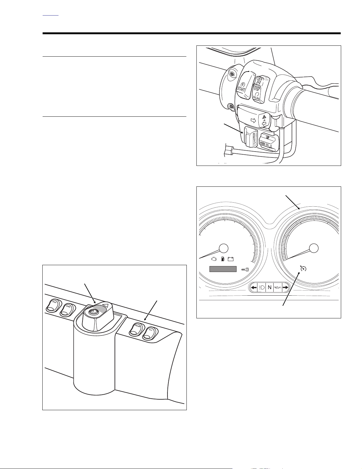
1. While riding in fourth or fifth gear, turn the Cruise ON/
OFF Switch to the ON position. See Figure 7-1. The
switch is located on the fairing cap of FLHTCU models,
the instrument nacelle of FLTR models, and the left handlebar lower switch housing on FLHRC models. The
Cruise Enabled/Engaged lamp in the tachometer face
(speedometer on FLHRC models) turns red to indicate
that the system is activated. See Figure 7-3. A red lamp
in the switch on both FLHTCU and FLTR models also
indicates this condition to the rider.
2. Power (12 vdc) is supplied to the cruise control module
through a 15 amp fuse located in the fuse block mounted
under the left side cover.
3. With the motorcycle traveling at the desired “cruise”
speed (30 mph/48 km/h to 85 mph/137 km/h), momentarily push the Cruise SET/RESUME switch to SET. See
Figure 7-2.
Figure 7-2. Right Handlebar Switch Assembly
(FLTR, FLHTCU)
Ignition/Light
Key Switch
Cruise ON/OFF
Switch
Figure 7-3. Instrument Panel (FLHTCU)
The cruise control module “reads” the vehicle speed sensor (VSS) output to establish the desired vehicle speed.
The module then sends a signal to the stepper motor
which drives the ribbon reel to take up the slack in the
cruise cable. The Cruise Enabled/Engaged lamp in the
tachometer face (speedometer on FLHRC models) turns
from red to green to indicate that the cruising speed is
f2031x8x
Figure 7-1. Fairing Cap (FLHTCU)
locked in. See Figure 7-3.
4. The cruise control module monitors both the engine
RPM and the VSS output speed signal. The module signals the stepper motor to open or close the throttle to
keep the speedometer output speed signal constant. The
engine RPM is monitored to detect engine
2004 Touring: Cruise Control 7-1
Page 2
HOME
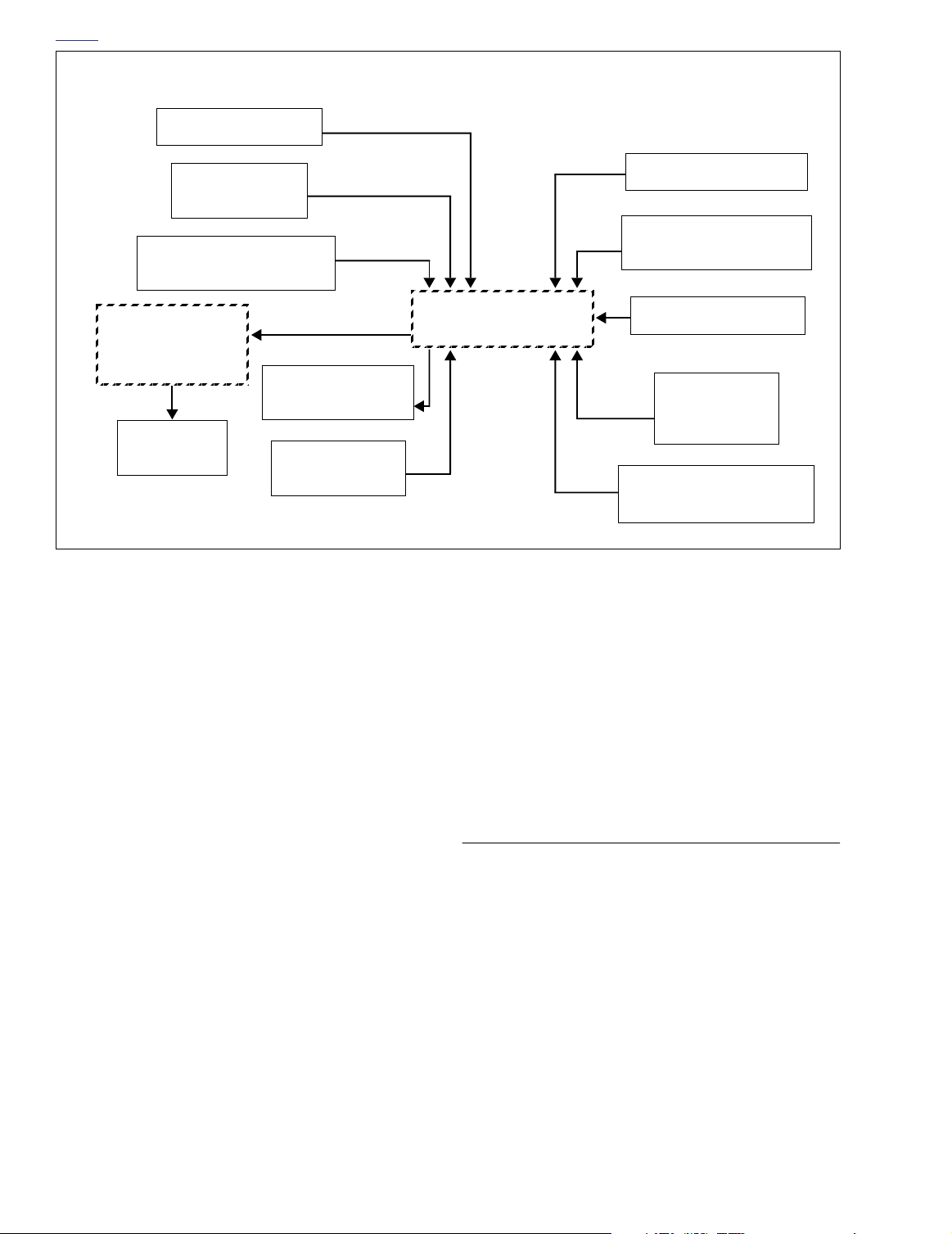
DISENGAGE SEQUENCEENGAGE SEQUENCE
CRUISE SWITCH ON
SET/RESUME
SWITCH TO SET
READS VSS
OUTPUT SPEED SIGNAL
STEPPER MOTOR
GEAR TRAIN
& RIBBON REEL
CRUISE ENGAGED
LAMP
THROTTLE
ACTUATION
*Tachometer receives signal from ignition coil on
carbureted models, and from ECM on EFI models.
overspeed, a condition which automatically causes
cruise disengagement.
5. The cruise control automatically disengages (stepper
motor drives cruise cable to the full-out position) whenever the cruise control module receives one of the following inputs:
a. Front or rear brake is applied.
b. Throttle is “rolled back” or closed, thereby actuating
idle cable roll-off (disengage) switch.
ENGINE RPM
MONITORED*
Figure 7-4. Cruise System Diagram
FRONT/REAR BRAKE
IDLE CABLE ROLL-OFF
(DISENGAGE) SWITCH
CRUISE
MODULE
f. Handlebar mounted Cruise SET/RESUME switch is
pushed to SET and held in that position until vehicle
speed drops below 30 mph (48 km/h).
If the vehicle speed is above 30 mph (48 km/h) when the
Cruise SET/RESUME Switch is released, then the cruise system automatically re-engages.
CRUISE SWITCH OFF
HANDLEBAR
ENGINE STOP
SWITCH OFF
CLUTCH DISENGAGE
(ENGINE RPM)
NOTE
c. Motorcycle clutch is disengaged (module senses too
great an increase in RPM).
d. Cruise ON/OFF Switch placed in the OFF position.
The switch is located on the fairing cap of FLHTCU
models, the instrument nacelle of FLTR models, and
the left handlebar lower switch housing on FLHRC
models. The green Cruise Enabled/Engaged lamp in
the tachometer face (speedometer on FLHRC models) is extinguished to indicate that the system is
deactivated. The red lamp in the fairing cap switch of
FLHTCU models and the instrument nacelle switch
of FLTR models is also extinguished.
e. Handlebar mounted Engine Stop Switch placed in
the OFF position. (This removes tachometer input
signal which results in module disengagement.)
7-2 2004 Touring: Cruise Control
TROUBLESHOOTING
The cruise module circuitry provides on-board diagnostics to
help isolate any problems that might occur with the cruise
system.
If the cruise is inoperative or fails to set, begin troubleshooting
with 7.2 CRUISE INOPERATIVE DIAGNOSTICS. If the cruise
seems to disengage or drop out for no apparent reason, then
see 7.3 CRUISE DROPOUT DIAGNOSTICS.
In the diagnostic mode, the Cruise Enabled/Engaged lamp is
employed as a test indicator. The lamp is in the tachometer
face (speedometer on FLHRC models). See Figure 7-3.
Page 3
HOME
CRUISE INOPERATIVE DIAGNOSTICS 7.2
GENERAL
Perform the following diagnostic procedures in the order presented. If the test sequence is not followed precisely, the
diagnostic mode may not be exited at conclusion of the diagnostic routine and the test indicator (Cruise Engaged Lamp)
may continue to flash while the engine is running.
INOPERATIVE DIAGNOSTICS
See Ta b l e 7-2. All diagnostic steps are listed in table format.
Follow the numbered steps to test the system. Compare the
system behavior to CORRECT FUNCTION or INCORRECT
FUNCTION columns and advance to the next step listed.
Diagnostic Notes
The diagnostic notes below provides supplementary information for Ta ble 7-2.
1. If the cruise engaged lamp does not illuminate at all,
check for one or more of the following conditions:
a. SET/RESUME switch faulty or not wired correctly.
b. Broken or pinched wire to SET switch or cruise mod-
ule.
c. Cruise engaged lamp burned out or miswired. Lamp
is turned on by module supplied ground.
d. Main 10-place connector not plugged into cruise
module.
e. Faulty cruise main switch and associated wiring.
f. No module ground at Terminal E of 10-place module
connector.
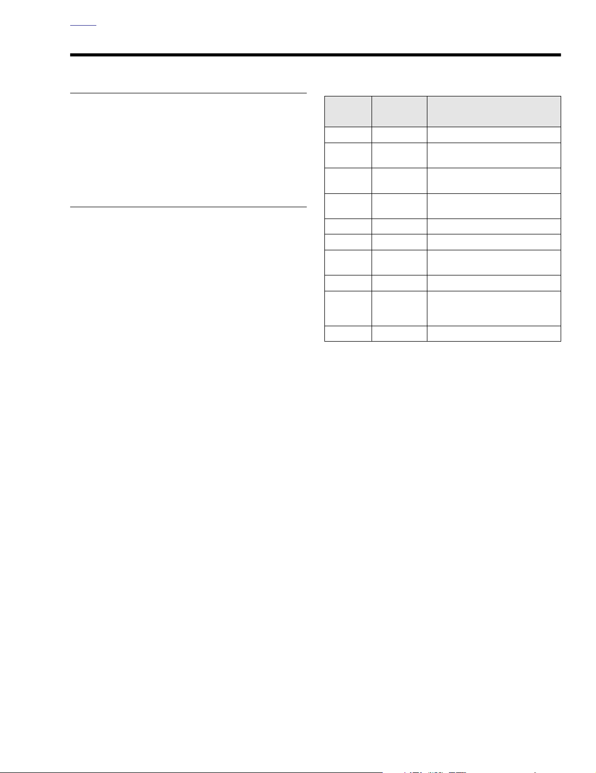
Table 7-1. Cruise Module Connector [17A]
TERMINAL
A Red/Green ON/OFF switch enable
BBlue/Black
C White/Blue
DViolet/Yellow
EBlack Cruise module ground
FOrange/Violet 12 vdc power from 15 amp fuse
G Red/Blue
HBlue/Orange Tachometer input
JGreen/Red
KWhite/Green Vehicle speed signal input
WIRE
COLOR
SET input from SET/RESUME
switch
RESUME input from SET/RESUME
switch
Idle cable disengage switch
(12 vdc from 15 amp fuse)
Disengage from brake relay
(12 vdc)
12 vdc from “CRUISE” indicator in
instrument panel
(module provides ground)
g. Brake light on constantly.
h. Throttle cables too tight.
i. Bad cruise control fuse.
2. Repeat Steps 1 and 2. If the cruise engaged lamp still
does not illuminate, see 7.4 CRUISE CHART A: INITIAL
DIAGNOSTICS. For cruise module connector wire color
locations and functions, see Ta bl e 7-1. Repair any problems and recheck by repeating Steps 1 and 2.
FUNCTION AND
CONNECTION
2004 Touring: Cruise Control 7-3
Page 4

HOME
Table 7-2. Cruise Inoperative Diagnostics
NO.
Tu rn the Ignition/Light Key Switch to
OFF. Connect Speedometer Tester
1
(HD-41354).
Enter the diagnostic mode: With the
fairing cap Cruise ON/OFF Switch at
ON, and the handlebar mounted
2
Cruise SET/RESUME Switch
at SET, turn the Ignition/Light Key
Switch to IGNITION.
Push the handlebar mounted Cruise
SET/RESUME Switch to RES(UME)
3
and hold in this position.
Next, turn the throttle grip tightly
closed to check the throttle grip
4
switch.
ACTION CORRECT FUNCTION INCORRECT FUNCTION
The cruise engaged lamp will illuminate and
remain on as long as the Cruise SET/
RESUME switch is held in the SET position.
held
Continue with Step 3.
The cruise engaged lamp will illuminate and
remain on as long as the SET/RESUME
Switch is held in the RES(UME) position.
Continue with Step 4.
The cruise engaged lamp will illuminate when
the switch is closed, and then be extinguished
when the throttle grip returns to its free position.
Continue with Step 5.
If the cruise engaged lamp remains illuminated after the switch is released, then either
the switch or related wiring is shorted. See
Diagnostic Note 1 for possible causes.
Continue with steps listed under Diagnostic Note 2.
If the cruise engaged lamp does not illuminate
at all, check for one or more of the following
conditions:
RES(UME) switch not wired correctly.
●
Broken or pinched wire to RES(UME)
●
switch or cruise module.
Continue with 7.5 CRUISE CHART B:
RESUME SWITCH.
If the cruise engaged lamp does not illuminate
at all, check for one or more of the following
conditions:
Throttle grip switch not wired correctly.
●
Broken or pinched wire to throttle grip
●
switch or cruise module.
Throttle grip switch not working correctly.
●
Continue with 7.11 CRUISE CHART G:
THROTTLE SWITCH.
Apply the brake hand lever.
5
Press and hold the brake foot pedal
6
for at least 5 seconds.
The cruise engaged lamp will illuminate and
remain on until the brake lever is released.
Continue with Step 6.
The cruise engaged lamp will illuminate. After
depressing and holding the brake foot pedal
for 5 seconds, the lamp will be extinguished.
Release the brake pedal and the cruise module will momentarily pull the throttle open
slightly and then release.
Continue with Step 7.
If the cruise engaged lamp does not illuminate
at all, check for one or more of the following
conditions:
●
Front brake switch not wired correctly.
●
Broken or pinched wire to front brake
switch or cruise module.
●
Front brake switch not working properly.
See 7.9 CRUISE CHART F-1: BRAKE
LIGHTS ON (constant brake light input) or
7.10 CRUISE CHART F-2: BRAKE LIGHTS
OFF (no front and/or rear brake lights).
The cruise engaged lamp will not illuminate if
any of the following conditions exist:
●
Rear brake switch not wired correctly.
●
Broken or pinched wire to rear brake
switch or cruise control module.
●
Rear brake switch not working properly.
The throttle will not open if the following conditions exist:
●
Cables not adjusted properly.
●
Faulty cruise control module.
See 7.9 CRUISE CHART F-1: BRAKE
LIGHTS ON (constant brake light input) or
7.10 CRUISE CHART F-2: BRAKE LIGHTS
OFF (no front and/or rear brake lights).
7-4 2004 Touring: Cruise Control
Page 5

HOME
Table 7-2. Cruise Inoperative Diagnostics
NO.
Rotate rear wheel.
7
Tu rn the fairing cap Cruise ON/OFF
Switch and the Ignition/Light Key
8
Switch to OFF. Disconnect spark
plug wires.
Press SET/RESUME Switch to
9
RES(UME), and hold.
While holding SET/RESUME Switch
at RES(UME), turn Ignition/Light Key
Switch to ON and crank engine. (If
10
weak battery or poor connections
result in low system voltage, Diagnostic Mode may be aborted.)
ACTION CORRECT FUNCTION INCORRECT FUNCTION
The cruise engaged lamp will flash on and off
indicating that the vehicle speed signal is
wired properly and working correctly.
Continue with Step 8.
Continue with Step 9.
Continue with Step 10.
The cruise engaged lamp flashes with RPM
input.
Continue with Step 11.
The cruise engaged lamp will not illuminate if
any of the following conditions exist:
Vehicle speed signal not wired correctly.
●
Broken or pinched wire to speedometer.
●
Speedometer not working properly.
●
Vehicle speed signal wiring discon-
●
nected.
See 7.12 CRUISE CHART H: SPEEDOME-
TER INPUT.
The cruise engaged lamp does not flash with
RPM input.
See 7.13 CRUISE CHART I: TACHOMETER
INPUT.
While continuing to hold SET/
RESUME Switch at RES(UME), turn
11
fairing cap Cruise ON/OFF Switch to
ON. Release SET/RESUME Switch.
To restart or repeat the diagnostic
12
sequence, return to Step 1.
Cruise engaged lamp blinks twice.
NOTE: Lamp may go on for three seconds if
RPM signal was above cranking speed.
DIAGNOSTIC ROUTINE EXITED
2004 Touring: Cruise Control 7-5
Page 6
HOME
CRUISE DROPOUT DIAGNOSTICS 7.3
GENERAL
To check for diagnostic codes, see DROPOUT DIAGNOS-
TICS below. If other problems are experienced, such as
harsh cruise engagement or speed loss, see Ta ble 7-4.
DROPOUT DIAGNOSTICS
The last eight diagnostic codes for cruise disengagement are
stored in memory.
1. To enter the diagnostic mode, turn the engine off and
proceed as follows:
a. Turn the fairing cap Cruise ON/OFF switch to OFF.
The light in the rocker switch is extinguished to indicate this condition to the operator.
b. Push the Cruise SET/RESUME Switch on the right
handlebar to SET and hold
c. Turn the Ignition/Light Key Switch to IGNITION, but
do not start the engine.
d. Release the Cruise SET/RESUME Switch from the
SET position while observing the behavior of the
Cruise Enabled/Engaged Lamp on the tachometer
gauge (speedometer on FLHRC models).
2. The system transmits the most recent cruise dropout
code. Each dropout code consists of 3 digits and is sent
out as a series of flashes.
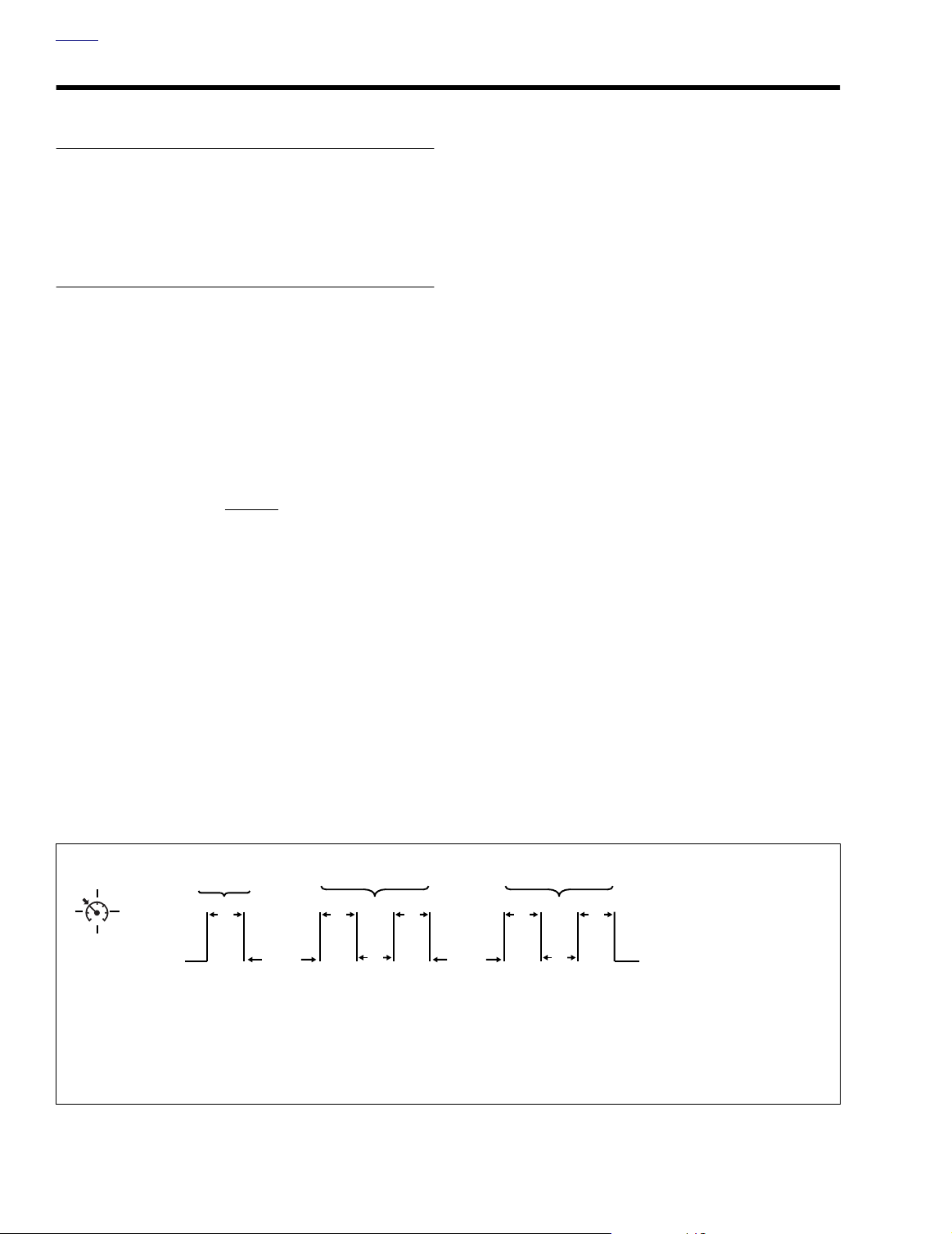
3. The lamp will begin by flashing one or more times to indicate the first digit of the dropout code. The length of time
the lamp is illuminated and the length of time in which it
is off are each about 1/4 second in duration. Simply
.
count the number of times the lamp flashes in order to
retrieve the first digit of the dropout code.
4. Following transmission of the first digit, there is a one
second pause in which the lamp is off. The lamp will then
flash one or more times to indicate the second digit of the
dropout code. Count the number of times the lamp
flashes to retrieve the second digit. See Figure 7-5.
5. Following transmission of the second digit, there is a
another one second pause in which the lamp is off. The
lamp will then flash one or more times to indicate the
third digit of the dropout code. Again, count the number
of times the lamp flashes to retrieve the third digit.
6. Write down the dropout code on a piece of paper. To
identify the reason for cruise disengagement see Ta bl e
7-3. The last column of the table suggests the appropri-
ate corrective action.
7. To verify the dropout code, toggle the Cruise SET/
RESUME Switch to RESUME. The transmission of the
most recent dropout code is repeated. To continue with
the next code, simply toggle the Cruise Switch to SET. All
subsequent codes are sent in the same manner as the
first, after which the operator may repeat the code or
move on to the next in the series.
8. After the eighth (or oldest) dropout code is flashed, the
Cruise Engaged Lamp remains illuminated to indicate
that the end of the dropout code buffer has been
reached.
9. To start the sequence at the beginning, that is, with
transmission of the most recent dropout code, momentarily push the Cruise SET/RESUME Switch to SET.
10. To exit the diagnostic mode, turn the Ignition/Light Key
Switch to OFF.
1st Digit 2nd Digit
ON
OFF
Cruise
Engaged
Lamp
1/4
Sec.
Pause After
1 Sec. 1 Sec.
1st Digit
Figure 7-5. Cruise Engaged Lamp Dropout Code Timing Diagram
7-6 2004 Touring: Cruise Control
1/4
Sec.
1/4
Sec.
3rd Digit
1/4
Sec.
Pause After
1/4
Sec.
1/4
Sec.
1/4
Sec.
Tog gle Cruise Switch to RESUME
to Verify Code.
Tog gle Cruise Switch to SET
to Continue With Next Code.
2nd Digit
NOTE
Looking at the above transmission, we can see that the dropout code is 122.
See Ta b le 7-3. The reason for cruise disengagement is identified as application of front or rear brakes.
Page 7

HOME
Table 7-3. Cruise Dropout Code Key
ACTION
CODE
111 Initial State or Cleared Memory (No Codes Recorded) 112 Throttle Roll Off 7.11 CRUISE CHART G: THROTTLE SWITCH
113 Fairing Cap Cruise Switch Turned OFF 7.8 CRUISE CHART E: CRUISE ENABLE
121 Short in Wiring Between Set/Resume
Application of Front or Rear Brakes
122
211 Coast (S/C Button Engaged) Interval Longer than 6 Seconds 7.4 CRUISE CHART A: INITIAL DIAGNOSTICS
212
213 Speed Drops Below 26 MPH or Exceeds 90 MPH 7.12 CRUISE CHART H: SPEEDOMETER INPUT
221
222 Speed Decreases Greater than 20 MPH per Second 7.12 CRUISE CHART H: SPEEDOMETER INPUT
223 Vehicle Speed Sensor Input 7.12 CRUISE CHART H: SPEEDOMETER INPUT
231 Over 5000 RPM 7.13 CRUISE CHART I: TACHOMETER INPUT
232 Loss of Tachometer Signal 7.13 CRUISE CHART I: TACHOMETER INPUT
242
311
312
313
321
323
331
332
333
341 Low Voltage 7.7 CRUISE CHART D: CRUISE POWER
342
343
351
352
353
361
362
363
371
423
432
777
May require inspection of brake levers
or front brake light switch mounting.
Speed Drops Below 30 MPH While in Coast
Speed Drops 15 MPH Below Set Speed
(Such as When Climbing a Steep Hill)
High Rate of Change of RPM Detected
(Such as When Clutch is Pulled In or Contact is Made
With Ice Patch or Slippery Surface)
CONDITION
NOTE
(S/C Button Engaged)
Internal Failure
Internal Failure
While performing instructions under applicable flow chart, wiggle connectors and wires to identify intermittents.
7.4 CRUISE CHART A: INITIAL DIAGNOSTICS or 7.5
CRUISE CHART B: RESUME SWITCH
7.9 CRUISE CHART F-1: BRAKE LIGHTS ON
7.4 CRUISE CHART A: INITIAL DIAGNOSTICS or 7.12
CRUISE CHART H: SPEEDOMETER INPUT
7.12 CRUISE CHART H: SPEEDOMETER INPUT
7.13 CRUISE CHART I: TACHOMETER INPUT
Replace cruise module. See the 2004 Touring Models Service
Replace cruise module. See the 2004 Touring Models Service
Manual (Part Number 99483-04).
Manual (Part Number 99483-04).
NOTE
2004 Touring: Cruise Control 7-7
Page 8

HOME
Table 7-4. Other Malfunctions
CONDITION
Harsh
engagement
Speed
variation
SYMPTOM CHECK FOR
Cruise control opens
throttle abruptly or harshly
Loses speed
Gains speed
Check for a cruise cable that is too tight. See CABLE LASH INITIALIZATION in the 2004 Touring Models Service Manual (Part
Number 99483-04).
●
Cruise cable too loose. See CABLE LASH INITIALIZATION in
the 2004 Touring Models Service Manual (Part Number
99483-04).
●
Set switch held too long.
●
Cruise cable too tight. See CABLE LASH INITIALIZATION in
the 2004 Touring Models Service Manual (Part Number
99483-04).
Intermittent vehicle speed signal.
●
Intermittent speedometer.
●
●
Defective cruise module. See CRUISE MODULE, REMOVAL/
Speed surges
INSTALLATION, in the 2004 Touring Models Service Manual
(Part Number 99483-04).
Check for surging with cruise control turned OFF. If surging is still
present, a lean fuel mixture may be the cause.
NOTE
7-8 2004 Touring: Cruise Control
Page 9

HOME
CRUISE CHART A: INITIAL DIAGNOSTICS 7.4
DIAGNOSTICS
Test 7.4 (Part 1 of 2)
Remove Left Saddlebag and Sidecover.
Is 10-place Connector [17B] Plugged Into
Cruise Module? See Figure 7-6.
YES
SET SWITCH
Check Continuity Between the O/V Terminal (F) and BE/BK Terminal (B) of Connector [17B]. Resistance Must Be
Pressing SET/RESUME Switch to SET
Should Produce a Reading of Less Than
0.5 Ohms. Are These Your Observations?
YES
∞ Ohms.
NO
STOP
Go to Test 7.4 (Part 2 of 2)
YES
NO
Plug In Connector [17B].Unplug Connector [17B].
FLHRC-I
Remove the Headlamp Assembly. Disconnect 6-Place Connector [22] and 2-Place
Connector [159]. Measure Resistance
Between O/W Wire on Connector [22B]
and BE/BK Wire on Connector [159B].
Resistance Must Be
SET/RESUME Switch to SET Should Produce a Reading of Less Than 0.5 Ohms.
Are These Your Observations?
∞ Ohms. Pressing
NO
Remove the Outer Fairing. Locate the 12Place Connector [22] for Right Handlebar
Switch Controls. See Figure 7-8 or Figure
7-8. Measure Between the O/W and BE/
BK Terminals at Connector [22B]. Resis-
tance Must Be ∞ Ohms. Pressing SET/
RESUME Switch to SET Should Produce
a Reading of Less Than 0.5 Ohms. Are
These Your Observations?
FLH TCU-I, FLTR/I
YES
Check Continuity on O/V
and BE/BK Wires Between
Connectors [17B] and
[156A]. See Figure 7-7 and
Figure 7-9. Continuity
Present?
YES
Repair
Interconnect
Harness.
6532
NO
Repair Main
Harness.
Right Handlebar
Switch Wiring
YES
Repair
Wiring.
6552
5028
NO
Pinched or
Damaged?
Replace Cruise
SET/RESUME
NO
Switch.
5182
Cruise Module
Connector [17]
Figure 7-6. Left Side Cover Removed
Locate and Repair
Open on BE/BK Wire
in Main Harness.
Switch Wiring Pinched
5028
Right Handlebar
or Damaged?
YES
Repair
Wiring.
6552
f2206x8x
NO
Replace Cruise
SET/RESUME
Switch.
5182
After correction of problem, restart 7.2 CRUISE
INOPERATIVE DIAGNOSTICS to verify proper per-
formance.
2004 Touring: Cruise Control 7-9
Page 10

HOME
Test 7.4 (Part 2 of 2)
INITIAL DIAGNOSTICS
Continued from Test 7.4 (Part 1 of 2).
Connect a Jumper From the GN/R Terminal (J) to Ground. The Cruise Engaged
Lamp Should Illuminate When the Ignition/Light Key Switch is Positioned to
IGNITION. Does It?
Main to
Interconnect [156]
Right Handlebar
Switch Controls [22]
YES
Place the Positive Probe on the O/V Terminal (F) and the Negative Probe on the BK
Te r minal (E). With the Ignition/Light Key
Switch Positioned to IGNITION, the Meter
Should Read Battery Voltage. Does It?
YES
Place the Positive Probe on the R/GN Terminal (A) and the Negative Probe on the BK
Te r minal (E). With the Ignition/Light Key
Switch Positioned to IGNITION and the Fairing Cap Cruise ON/OFF Switch Positioned
to ON, the Meter Should Read Battery Voltage. Does It?
YES
Place the Positive Probe on the R/BE
Te r minal (G) and the Negative Probe on
the BK Terminal (E). Meter Should Read
Between 11-13 Volts Only When the
Brake is Applied and the Ignition/Light
Key Switch is Positioned to IGNITION.
Does It?
NO
See 7.6 CRUISE
CHART C:
CRUISE
ENGAGED LAMP.
NO
See 7.7 CRUISE
CHART D:
CRUISE POWER.
NO
See 7.8 CRUISE
CHART E:
CRUISE
ENABLE.
f2238x8x
Figure 7-7. Outer Fairing Removed (FLHTC/U)
Right Handlebar
Switch Controls [22]
Main to
Interconnect [156]
YES
Check Continuity Between the V/Y
Te rminal (D) and the O/V Terminal (F)
With the Ignition/Light Key Switch
Positioned to OFF
Read Infinity When the Throttle Switch
is in the Relaxed Position, and Continuity When the Throttle Grip is Rolled
Forward. Does It?
Reconnect All Connectors. Restart
7.2 CRUISE INOPERATIVE DIAGNOSTICS if Cruise Engaged Lamp
has Never Illuminated. If the Lamp
Will Not Illuminate When the First Test
is Performed Now, Replace the
Cruise Module.
. The Meter Should
YES
6635
7-10 2004 Touring: Cruise Control
NO
See 7.9 CRUISE
CHART F-1: BRAKE
LIGHTS ON or 7.10
CRUISE CHART F-
2: BRAKE LIGHTS
OFF.
NO
See 7.11 CRUISE
CHART G: THROTTLE
SWITCH.
f2230x2x
Figure 7-8. Outer Fairing Removed (FLTR)
Page 11

HOME
CRUISE CHART B: RESUME SWITCH 7.5
DIAGNOSTICS
Test 7.5
Remove Left Saddlebag and Side Cover. Disconnect Connector [17B] From Cruise Module.
See Figure 7-6. Check Continuity Between the O/V Terminal (F) and the W/BE Terminal (C).
Resistance Must Be
duce a Reading of Less Than 0.5 Ohms. Are These Your Observations?
∞ Ohms. Pressing SET/RESUME Switch to RESUME Should Pro-
YES
Replace
Cruise
Module.
FLH TCU-I, FLTR/I
6635
Remove the Outer Fairing. Locate the 12-Place Connector [22] for Right Handlebar Switch Controls. See
Figure 7-8 or Figure 7-8. Measure Between O/W and
W/BE Terminals at Connector [22B].
Resistance Must Be
RESUME Switch to RESUME Should Produce a
Reading of Less Than 0.5 Ohms. Are These Your
Observations?
Check Continuity on W/BE Wire
Between Connectors [17B] and
[156A]. See Figure 7-7 and Fig-
ure 7-7. Continuity Present?
YES
Repair
Interconnect
Harness.
∞ Ohms. Pressing SET/
YES
Repair Main
Harness.
6532
NO
Right Handlebar
Switch Wiring Pinched
YES
Repair
Wiring.
5028
NO
or Damaged?
Replace Cruise
SET/RESUME
6552
NO
FLHRC-I
Disconnect 6-Place Connector [22] and 4-Place
Connector [159]. Measure Resistance Between O/W
Wire at Connector [22B] and W/BE Wire at Connector [159B].
Resistance Must Be
RESUME Switch to RESUME Should Produce a
Reading of Less Than 0.5 Ohms. Are These Your
Observations?
Locate and Repair
Open on W/BE Wires
in Main Harness.
NO
Switch.
5182
∞ Ohms. Pressing SET/
YES
5028
Right Handlebar
Switch Wiring Pinched
or Damaged?
YES
Repair
Wiring.
6552
NO
Replace Cruise
SET/RESUME
Switch.
NO
5182
After correction of problem, restart 7.2 CRUISE INOPERATIVE DIAGNOSTICS
to verify proper performance.
2004 Touring: Cruise Control 7-11
Page 12

HOME
CRUISE CHART C: CRUISE ENGAGED LAMP 7.6
DIAGNOSTICS
Test 7.6
Remove Left Saddlebag and Side Cover. Disconnect Connector [17B] From
Cruise Module. See Figure 7-6. Connect a Jumper From the GN/R Terminal
(J) to Ground. The Cruise Engaged Lamp Should Illuminate When the Ignition/Light Key Switch is Positioned to IGNITION. Does it?
YES
Replace
Cruise
Module.
6635
NO
FLH TCU-I, FLTR/I
Remove Outer Fairing (FLHTCU-I) or
Instrument Bezel (FLTR/I). Remove GN/R
Wire From Connector [108B] and Then
Reconnect. Connect a Jumper Wire to
Ground From the GN/R Wire That Feeds
the Tachometer. The Cruise Engaged Lamp
Should Illuminate When the Ignition/Light
Key Switch is Positioned to IGNITION.
Does It?
YES
Repair
Interconnect
Harness.
6532
NO
Replace
Tachometer.
6009
FLHRC-I
Continuity Present on
GN/R Wire Between
Connectors [159A]
and [17B]?
YES
Battery Voltage
Present on O/W Wire
at Connector [22A]?
YES
Handlebar Switch
Wiring Pinched or
Damaged?
YES
6552
Replace Cruise
Engaged Lamp.
Repair
Wiring.
NO
5182
NO
Locate and
Repair Open
on GN/R Wire.
5028
NO
Accessory
Fuse OK?
YES
Locate and Repair
Open on O/W Wire
Between Accessory
Fuse and Connector
[22A].
5028
NO
Replace 15 Amp
Accessory Fuse.
5145
After correction of problem, restart 7.2 CRUISE INOPERATIVE DIAGNOSTICS
to verify proper performance.
7-12 2004 Touring: Cruise Control
Page 13

HOME
CRUISE CHART D: CRUISE POWER 7.7
DIAGNOSTICS
Test 7.7
Remove Left Saddlebag and Side Cover. Disconnect Connector [17B] From Cruise Module. See Figure 7-6.
Place the Positive Probe on the O/V Terminal (F) and the Negative Probe on the BK Terminal (E). With the Igni-
tion/Light Key Switch Positioned to IGNITION, the Meter Should Read Battery Voltage. Does It?
YES
Replace
Cruise
Module.
6635
NO
Check Continuity Between the
BK Terminal (E) and Ground.
Continuity Present?
YES
Check for Continuity Between
O/V Terminal (F) and the 15
Amp Cruise Fuse. Continuity
Present? See Figure 7-10.
YES
Check for Power at
R/GY Wire in Fuse
Block. Power Present?
YES
Replace
15 Amp
Fuse.
5145
Correct Open in
Ground Wire.
NO
Repair Open
Between Cruise
Fuse and R/GY
Wire of Ignition
Switch.
NO
5038
NO
Locate and Repair Open on
O/V Wire Between Cruise
Fuse and Connector [17B].
5028
5028
After correction of problem, restart 7.2 CRUISE INOPERATIVE DIAGNOSTICS
to verify proper performance.
2004 Touring: Cruise Control 7-13
Page 14

HOME
1. Right Handlebar Switch Controls [22]
2. Main to Interconnect Harness [2]
3. Speedometer Gauge [39]
4. Left Handlebar Switch Controls [24]
7
2
6
5. Fairing Cap (FLHTCU)
6. Main to Interconnect Harness [1]
7. Main to Interconnect Harness [156]
FLHTC/U
3
4
f2230x2x
5
1
f2238x8x
FLTR
1
7
4
6
2
7-14 2004 Touring: Cruise Control
Figure 7-9. Outer Fairing Removed
Page 15

HOME
CRUISE CHART E: CRUISE ENABLE 7.8
DIAGNOSTICS
Test 7.8
Remove Left Saddlebag and Side Cover. Disconnect Connector [17B] From Cruise Module.
See Figure 7-6.
Place Positive Probe on R/GN Terminal (A) and the Negative Probe on the BK Terminal (E).
With the ignition and Cruise Switches On, the Meter Should Read Battery Voltage. Does It?
NO
YES
NO
Disconnect Connector [105]. See Figure
7-9. Measure Volt-
age on O/V Wire of
5192
Connector [105A].
FLHRC-I
Battery Voltage
Present on Terminal 1
(R/GN Wire) of
Connector [158B]?
YES
Locate and
Repair Open
on R/GN Wire
Between Con-
nectors [158A]
and [17B].
5028
NO
Voltage Present?
YES
Replace
Cruise
Module.
6635
Check for Battery Voltage at R/GN
Wire of Connector [105]. See Fig-
ure 7-9. Voltage Present?
It may be necessary to open secondary lock to perform check.
YES
2
Check for Battery
Voltage at R/GN Wire
of Connector [156A].
See Figure 7-8 or
Figure 7-8. Voltage
Present?
Remove the Ignition/Light Key Switch
Knob and Fairing Cap to Access
Switch Terminals.
With the Ignition/Light Key Switch Positioned to IGNITION and the Fairing
Cap Cruise ON/OFF Switch Positioned
to ON, the Meter Should Read Battery
Voltage on the R/GN Terminal of the
Cruise Switch. Does It?
YES
NOTE
Repair Wire
Between Switch
and Connector
FLH TCU-I, FLTR/I
NO
[105].
5192
Measure Voltage at
O/V Terminal of
Switch. Meter Should
Read Battery
Voltage. Does It?
Replace Cruise
Enable
ON/OFF Switch.
Diagnostic Notes
1. Use HARNESS CONNECTOR KIT (Part
No. HD-41404), black pin probes and
patch cords.
2. Use HARNESS CONNECTOR KIT (Part
No. HD-41404), black socket probes and
patch cords.
1
NO
Battery Voltage
Present on Terminal
1 (O/W Wire) of
Connector [24A]?
YES
Handlebar Switch
Wiring Pinched or
Damaged?
YES
Repair
Handlebar
Wiring.
6552
Replace
Cruise
Enable
Switch.
NO
5128
2
NO
Accessory
Fuse OK?
YES
Locate and
Repair Open on
O/W Wire
Between Acces-
sory Fuse and
Connector [24A].
5028
NO
Replace
15 Amp
Accessory
Fuse.
5145
YES
Repair Main
Harness.
5028
NO
Repair or Replace
Interconnect
Harness.
6532
YES
Repair Open
Between Cruise
Switch and
Connector [105].
5192
After correction of problem, restart 7.2 CRUISE INOPERATIVE DIAGNOSTICS
to verify proper performance.
NO
Repair Open in
Interconnect
Harness.
6532
2004 Touring: Cruise Control 7-15
Page 16

HOME
CRUISE CHART F-1: BRAKE LIGHTS ON 7.9
DIAGNOSTICS
Test 7.9
CONSTANT BRAKE LIGHT INPUT
Ver ify That Front Brake Light Switch is Properly Positioned
Inside Lower Right Switch Housing (Retention Clip in Place).
Is It?
YES
Remove Left Saddlebag and Side Cover. Measure Voltage at R/BE Wire Terminal (86) of the
Brake Light Relay. See Figure 7-10. Meter
Should Read Battery Voltage Only When
Brakes are Applied. Does It?
YES
Replace Brake
Light Relay.
After correction of problem, restart 7.2 CRUISE INOPERATIVE DIAGNOSTICS
to verify proper performance.
Remove One of the Spade Terminals From the Rear Brake Light
Switch. Are Brake Lights Still Lit?
5169
Accessory
NO
Install
Retention Clip.
NO
YES
Replace Front
Brake Light Switch.
5176
NO
Replace Rear
Brake Light Switch.
5141
Brake Light
Relay
f2204x8x
Figure 7-10. Fuse Block (FLHTCU-I)
7-16 2004 Touring: Cruise Control
Brakes/Cruise
Page 17

HOME
CRUISE CHART F-2: BRAKE LIGHTS OFF 7.10
DIAGNOSTICS
Test 7.10 (Part 1 of 2)
NO FRONT AND/OR REAR BRAKE LIGHTS
Remove Left Saddlebag and Side Cover to
Access Brake Light Relay. See Figure 7-10.
With Ignition/light Key Switch Positioned to
IGNITION and Brakes Applied, Check for
Power on R/BE Wire at Terminal (86) of the
Brake Light Relay.
Meter Should Read Battery Voltage. Does It?
YES
Locate and
Repair Open on
R/BE Wire in
Main Harness.
5028
NO
With Ignition/Light Key Switch
Tu r ned to IGNITION and Rear
Brake Applied, Check for
Power at R/BE Wire of Rear
Brake Light Switch. Battery
Voltage Present?
YES
STOP
Go to Test 7.10 (Part 2 of 2)
NO
With Ignition/Light Key
Switch Turned to IGNITION, Check for Power at
O/W Terminal of Rear
Brake Light Switch. Battery
Voltage Present?
YES
Replace
Rear Brake
Light Switch.
5141
NO
Locate and Repair
Open on O/W
Wire in Main Har-
ness Between
Rear Brake Light
Switch and Acces-
sory Fuse.
5028
After correction of problem, restart 7.2 CRUISE INOPERATIVE DIAGNOSTICS
to verify proper performance.
2004 Touring: Cruise Control 7-17
Page 18

HOME
Test 7.10 (Part 2 of 2)
NO FRONT AND/OR REAR BRAKE LIGHTS
Continued from Test 7.10 (Part 1 of 2).
With Ignition/Light Key Switch Turned to IGNITION and Front Brake Applied, Check for
Power at R/BE Wire of Rear Brake Light
Switch. Battery Voltage Present?
Diagnostic Notes
1. Use HARNESS CONNECTOR KIT (Part
No. HD-41404), black pin probes and
patch cords.
2. Use HARNESS CONNECTOR KIT (Part
No. HD-41404), black socket probes and
patch cords.
YES
Repair Open in
Main Harness
Between Rear
Brake Light
Switch and Brake
Light Relay.
5028
Repair Open
Between Connector
[2B] and Rear Brake
Light Switch.
FLH TCU-I, FLTR/I
2
Remove Outer Fairing.
With Ignition/Light Key
Switch Turned to IGNITION
and Front Brake Applied,
Check for Power at R/BE
Wire of Connector [2B].
See Figure 7-9. Battery
Voltage Present?
YES
5028
YES
Repair Open in
R/BE Wire of
Interconnect
Harness.
NO
1
With Ignition/Light Key
Switch turned to IGNITION
and Front Brake Applied,
Check for Power at R/BE
Wire of Connector [22A].
See Figure 7-9. Battery
Voltage Present?
With Ignition/Light Key
Switch Turned to IGNITION,
Check for Power at O/W
Wire of Connector [22A].
Battery Voltage Present?
6532
YES
Handlebar Switch
Wiring Pinched or
Damaged?
NO
NO
Repair Open
in O/W Wire.
NO
FLHRC-I
1
Battery Voltage
Present on Terminal 1
(O/W Wire) of Con-
nector [22A]?
2
Check for Continuity
at Terminals 1 and 2
of Connector [22B]
With Front Brake
Applied. Continuity
Present?
Locate and Repair
Open on R/BE Wire
Between Connector
[22A] and Brake
Light Relay.
6532
YES
YES
5028
NO
Handlebar
Switch Wiring
Pinched or
Damaged?
YES
Repair
Handlebar
Wiring.
6552
NO
Accessory
Fuse OK?
YES
Locate and
Repair Open on
O/W Wire
Between Acces-
sory Fuse and
Connector [22A].
5028
NO
Replace
Front Brake
Light Switch.
5176
NO
Replace
15 Amp
Accessory
Fuse.
5145
YES
Repair
Wiring.
6552
After correction of problem, restart 7.2 CRUISE INOPERATIVE DIAGNOSTICS
to verify proper performance.
NO
Replace
Front Brake
Light Switch.
5176
7-18 2004 Touring: Cruise Control
Page 19

HOME
CRUISE CHART G: THROTTLE SWITCH 7.11
DIAGNOSTICS
Test 7.11
THROTTLE SWITCH
Remove Left Saddlebag and Side Cover. Disconnect Connector [17B] From
Cruise Module. See Figure 7-11.
With the Ignition/Light Key Switch Positioned to OFF
Between the V/Y Terminal (D) and the O/V Terminal (F). The Meter Should
Read Infinity When the Throttle Switch is in the Relaxed Position and Continuity When the Throttle Grip is Rolled Forward. Are These Your Observations?
, Check Continuity
YES
Restart 7.2 CRUISE INOPERA-
TIVE DIAGNOSTICS to Verify
That Problem is Corrected. If the
Cruise Engaged Lamp Will Not
Illuminate When This Step is
Performed Now, Replace The
Cruise Module.
6635
After correction of problem, restart 7.2 CRUISE INOPERATIVE DIAGNOSTICS
to verify proper performance.
Adjust the Idle Throttle Cable
and Retest for Continuity.
NO
Continuity Present?
YES
System
OK.
NO
Check for Continuity Directly at
Throttle Switch. Continuity
Should Only be Present When
the Throttle is Rolled Forward
Under Pressure. Is It?
YES
Battery Voltage
Present on O/V
Throttle Switch
Te rminal [75D]?
YES
Locate and
Repair Open
on Y/V Wire in
Main Harness.
5028
NO
Replace Idle
Throttle
Cable.
2241
NO
Locate and Repair
Open on O/V Throttle
Switch Wires in Main
Harness.
5028
Cruise Module
Connector [17]
Figure 7-11. Left Side Cover Removed
f2206x8x
2004 Touring: Cruise Control 7-19
Page 20

HOME
CRUISE CHART H: SPEEDOMETER INPUT 7.12
DIAGNOSTICS
Diagnostic Notes
1. To enable Diagnostic Mode, see 2.3 Speedometer selfdiagnostics.
Test 7.12 (Part 1 of 2)
1
Perform speedometer selfdiagnostics in Section 2.3. Is
P0501 or P0502 set?
YES
See P0501/P0502.
2
Disconnect connector [17]. Measure voltage at connector [17], terminal K (+) to ground. Is voltage
present?
NO
2. Use HARNESS CONNECTOR KIT (Part No. HD-41404),
gray pin probe and patch cord.
3. Use HARNESS CONNECTOR KIT (Part No. HD-41404),
black pin probe and patch cord.
YES
Locate and repair
short to voltage on
W/GN wire.
5028
After correction of problem, restart 7.2 CRUISE INOPERATIVE DIAGNOSTICS
to verify proper performance.
Measure continuity to ground at
connector [17B], Terminal K (+). Is
continuity present?
Locate and repair
short to ground on
W/GN wire.
NO
YES
Check continuity between connector [17B], terminal K (+) and connector [65B], terminal B. Is
continuity present?
5028
NO
YES
Replace
cruise
module.
6635
NO
Locate and
repair open
on W/GN
wire.
3
5028
7-20 2004 Touring: Cruise Control
Page 21

HOME
CRUISE CHART I: TACHOMETER INPUT 7.13
DIAGNOSTICS
Test 7.13
Remove Left Saddlebag and Side Cover. Disconnect Connector [17B] From Cruise Module. See
Figure 7-11.
Place the Positive Probe on the BE/O Terminal (H) and the Negative Probe on the BK Terminal (E).
The Meter Should Read Battery Voltage. If Voltage is Not Present, Momentarily Press the Starter
Button Until Voltage is Present. The Meter Should Read a Voltage Fluctuation During Cranking. Are
These Your Observations?
f1917x9x
YES
Replace
Cruise
Module.
6635
Ignition/EFI Harness
Connector [8]
NO
Remove Right Saddlebag and Side
Cover. Disconnect Gray 12-Place
Ignition/EFI Harness Connector [8].
See Figure 7-12. Check for Continuity Between the BE/O Terminal (H)
and the BE/O Wire in Connector
[8A]. Continuity Present?
YES
Locate and Repair
Open in BE/O Wire
(Carbureted) or PK
Wire (EFI) of Ignition/EFI Harness.
6532
After correction of problem, restart 7.2 CRUISE INOPERATIVE DIAGNOSTICS
to verify proper performance.
NO
Locate and
Repair Open in
Main Harness.
5028
Figure 7-12. Right Side Cover Removed
2004 Touring: Cruise Control 7-21
Page 22

HOME
NOTES
7-22 2004 Touring: Cruise Control
 Loading...