

Page 1
H
OME
SPECIFICATIONS 6.1
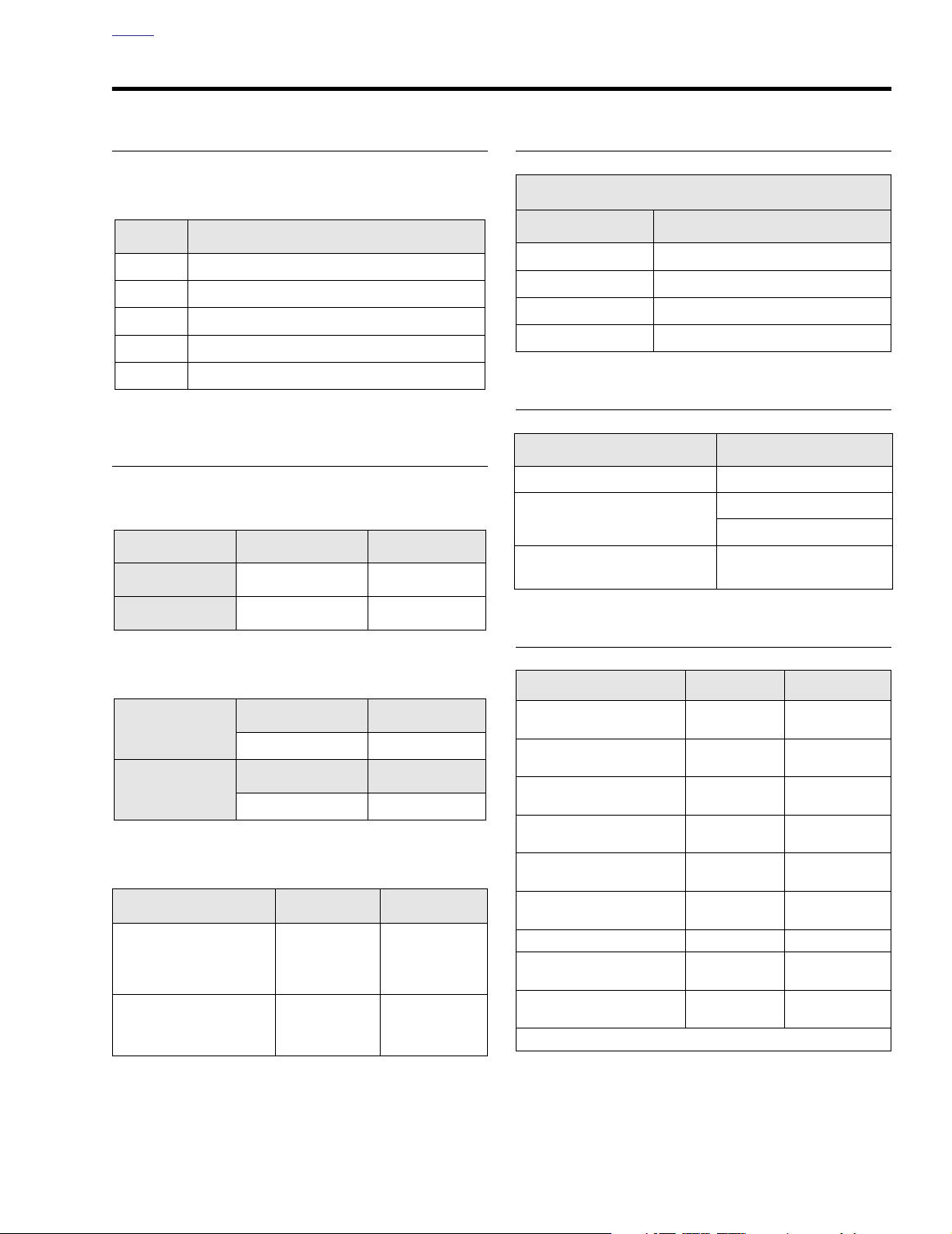
OVERALL GEAR RATIOS
Overall gear ratios indicate the number of engine revolutions
required to drive the rear wheel one revolution.
Gear
All Models
1 10.11
2 6.96
3 4.95
4 3.86
5 3.15
CHAINS AND BELTS
Primary Chain Adjustments
Free Play
COLD Engine
Inches Millimeters
5/8-7/8 inch 15.9-22.2 mm
SPROCKETS
Number of Teeth
Sprocket
Engine 25
Clutch 36
Tr ansmission 32
Rear wheel 70
All Models
CLUTCH
Clutch
Ty pe Wet-multiple disc
Clutch lever free play
Clutch screw adjustment
Description
1/16-1/8 in.
1.6-3.2 mm
loosen 1/2-1 turn after
lightly seating
HOT Engine
3/8-5/8 inch 9.5-15.9 mm
Primary Chaincase Lubricant
Ounces Milliliters
Amount
32 946
Quart Gallon
Part Number
99887-84 99886-84
Rear Belt Adjustment
Deflection
On Jiffy Stand Without
Rider or Luggage
10 psi (69 kPa)
in Rear Shocks
Motorcycle Upright
With Rear Wheel
in the Air
Inches Millimeters
1/4 - 5/16
at 10 lbs force
3/16 - 1/4
at 10 lbs force
6.4 - 7.9
at 4.5 kg force
4.8 - 6.4
at 4.5 kg force
TORQUE VALUES
Item
Primary chain tensioner
shoe nut
Te nsioner shoe adjuster
plate screws
Primary chain inspection
cover screws
Clutch adjuster screw
locknut
Clutch inspection cover
screws
Clutch diaphragm spring
retainer to clutch hub bolts
Rear axle cone nut 95-105 ft-lbs 129-142 Nm
Rear swingarm pivot
shaft locknut
Rear swingarm bracket
bolts
ft/in-lbs Nm
21-29 ft-lbs 29-39 Nm
12-14 ft-lbs 16-19 Nm
84-108
in-lbs
72-120
in-lbs
84-108
in-lbs
90-110
in-lbs
40-45 ft-lbs 54-61 Nm
34-42 ft-lbs
10-12 Nm
8-14 Nm
10-12 Nm
10-12 Nm
46-57 Nm
Continued ...
2004 Touring: Drive 6-1
Page 2

H
OME
TORQUE VALUES (CONT.’D)
Item
Shock bottom
mounting bolt
Exhaust pipe TORCA
clamps
Heat shield worm drive
clamp screws
Tr ansmission mainshaft
sprocket nut
Mainshaft sprocket nut
lockplate socket head
screws
Rear wheel sprocket bolts 55-65 ft-lbs 75-88 Nm
Primary chaincase to
crankcase and transmission
Front and rear starter
mounting screws
Starter jackshaft bolt 60-80
Engine compensating
sprocket nut
Clutch hub mainshaft nut 70-80 ft-lbs 95-108 Nm
Primary chaincase cover
allen head socket screws
Primary chaincase drain
plug
Passenger footboard
socket screws
Shifter lever
socket screws
1/4”
5/16”
ft/in-lbs Nm
35-40 ft-lbs 47-54 Nm
45-60 ft-lbs 61-81 Nm
20-40
in-lbs
60 ft-lbs, then
35° to 45°
90-110
in-lbs
18-21 ft-lbs 24-28 Nm
13-20 ft-lbs 18-27 Nm
in-lbs
150-165 ft-lbs 203-224 Nm
84-108
in-lbs
36-60
in-lbs
15-18 ft-lbs 20-24 Nm
90-110
in-lbs
18-22 ft-lbs 24-30 Nm
2.3-4.5 Nm
81 Nm, then
35° to 45°
10-12 Nm
6.8-9.0 Nm
9-12 Nm
4.1-6.8 Nm
10.2-12.4 Nm
6-2 2004 Touring: Drive
Page 3
H
CAUTION
f1840x6x
Primary
Chain
Retaining
Ring
Adjuster Shoe
Narrow End Forward
Top Center Nut
OME
PRIMARY CHAIN AND SPROCKETS 6.2
PRIMARY CHAIN ADJUSTMENT
At the 1000 mile (1600 km) service interval, and at every
5000 mile (8000 km) service interval thereafter, inspect the
primary chain tension. Proceed as follows:
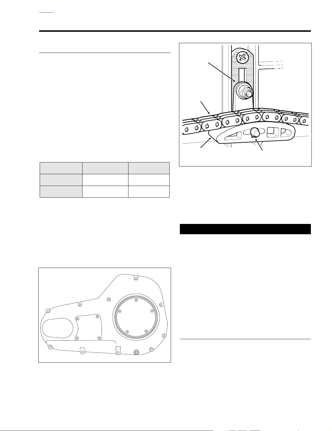
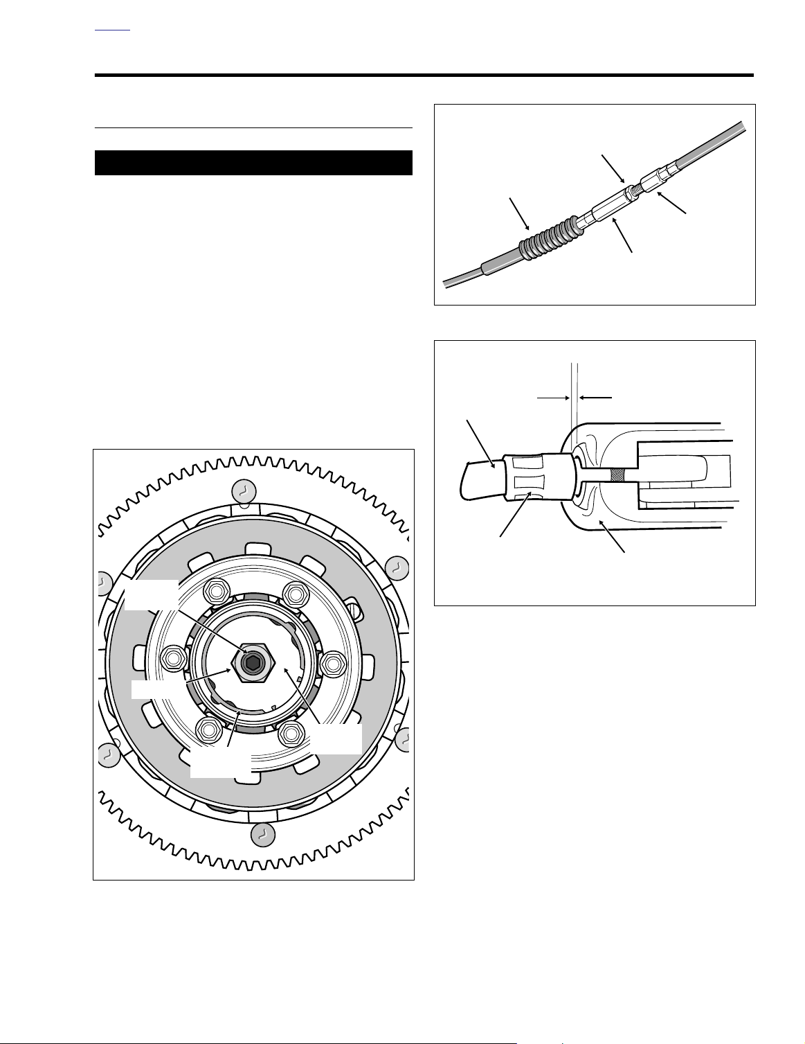
1. See Figure 6-1. Using a T27 TORX drive head, remove
four screws to free the primary chain inspection cover
from the primary chaincase cover.
2. Check the primary chain tension. Push on the upper
strand to verify that it has free up and down movement
midway between the engine compensating sprocket
(front) and the clutch sprocket (rear).
3. Measure the free play to be sure that it falls within the
ranges specified for a hot or cold engine:
Table 6-1. Primary Chain Adjustment
(Free Play)
COLD ENGINE
HOT ENGINE
Inches Millimeters
5/8-7/8 inch 15.9-22.2 mm
3/8-5/8 inch 9.5-15.9 mm
4. If the chain is too tight or too loose, then adjust as follows:
a. Locate the chain tensioner assembly and loosen the
top center nut a maximum of two turns. See Figure
6-2.
b. Raise or lower the chain tensioner assembly as
necessary to obtain the specified free play.
f1210x6x
1
4
Inspection
Primary
Chain
Cover
1
32
Clutch
43
Inspection
Cover
5
2
Figure 6-1. Primary Chaincase Cover
Figure 6-2. Chain Tensioner Assembly
NOTE
As chains stretch and wear, they run tighter at one spot than
another. Always adjust the free play at the tightest spot in the
chain. Replace the primary chain if it is worn to the point
where it cannot be properly adjusted.
Always keep the primary chain properly adjusted. Allowing the chain to run too tight or too loose will result in
excessive chain and sprocket wear.
c. Tighten the top center nut of the chain tensioner
assembly to 21-29 ft-lbs (29-39 Nm).
5. Align holes in
new
gasket with holes in the primary
chaincase cover. Using a T27 TORX drive head, install
four screws to secure primary chain inspection cover to
primary chaincase cover. Alternately tighten screws to
84-108
in-lbs
(10-12 Nm) in a crosswise pattern. See
Figure 6-1.
ADJUSTER SHOE REPLACEMENT
If the nylon adjuster shoe is worn or damaged, replace as follows:
1. Remove the primary chaincase cover. See Section 6.5
PRIMARY CHAINCASE, REMOVAL, steps 1-8.
2004 Touring: Drive 6-3
Page 4
H
OME
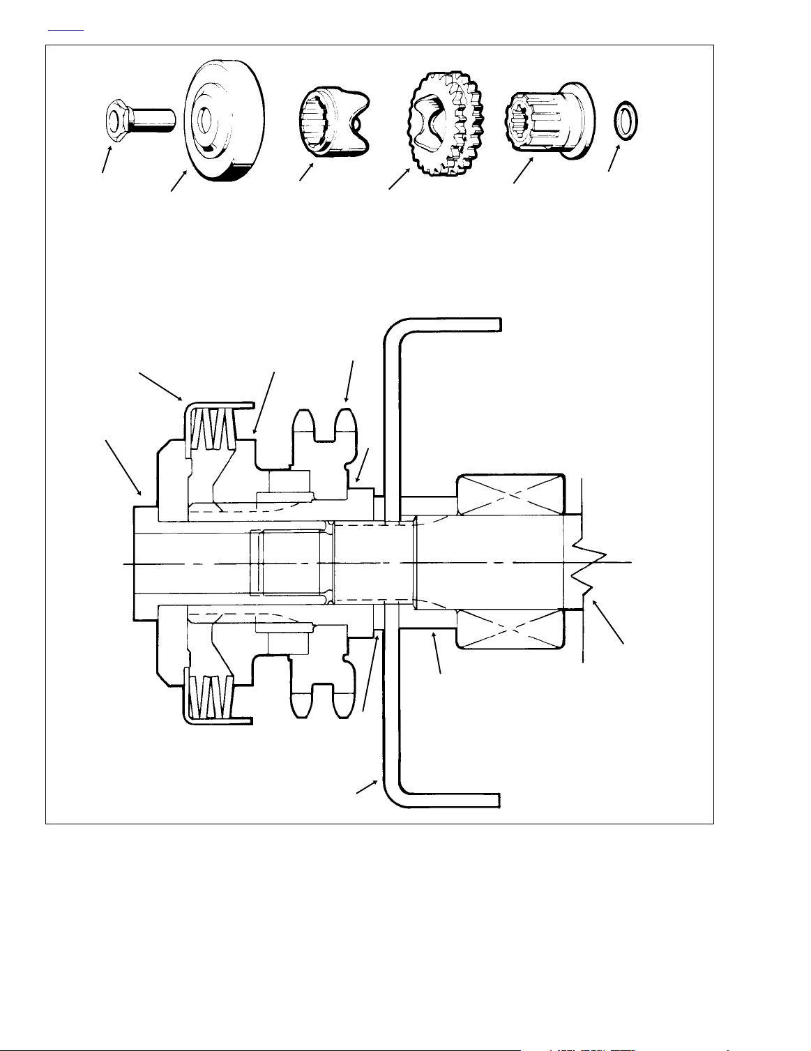
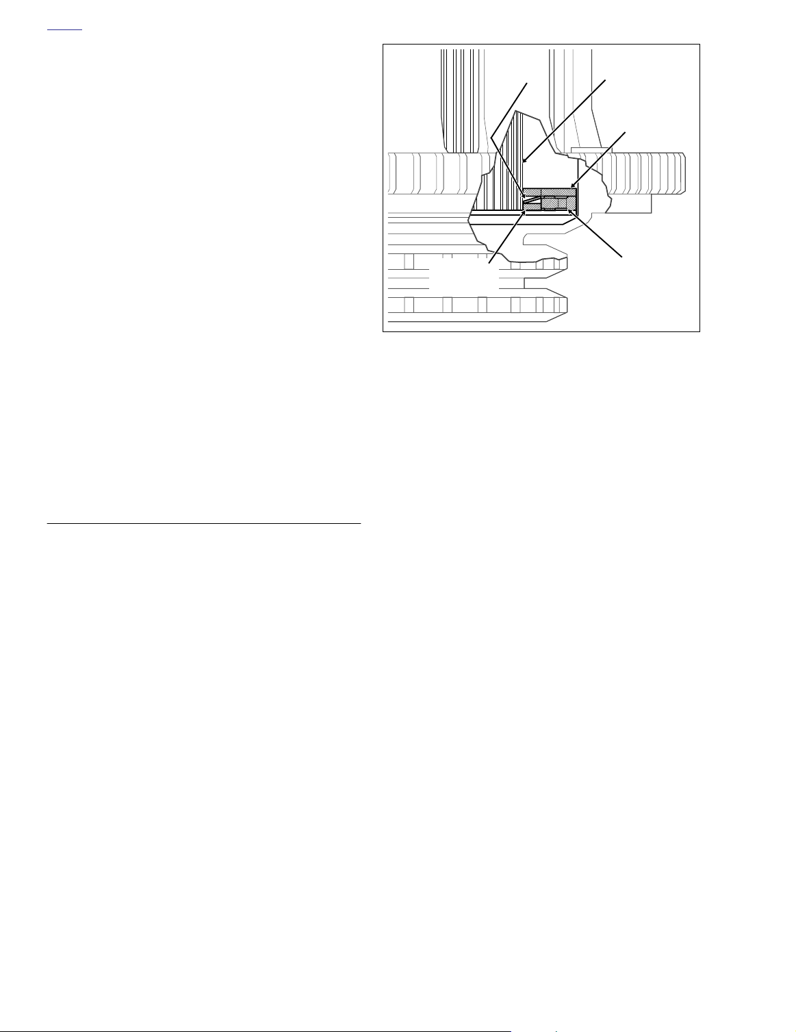
f1096dxd
1
2
1. Sprocket Nut
2. Sprocket Cover
3. Sliding Cam
4. Compensating Sprocket
5. Shaft Extension
EXPLODED VIEW
2
1
3
6. Alternator Rotor SpacerLow Output Rotor Only
0.020 inch (0.508 mm)
4
4
3
5
5
7. Alternator Rotor
8. Sprocket Shaft Spacer
9. Engine Sprocket Shaft
NOTE
Alternator stator, oil seal and left
crankcase not shown.
6
CROSS SECTIONAL VIEW
7
Figure 6-3. Engine Compensating Sprocket Components
2. Loosen top center nut from captured bolt of chain tensioner assembly. See Figure 6-2.
6-4 2004 Touring: Drive
9
8
6
3. Lower the chain tensioner assembly until the adjuster
shoe just contacts the inner primary housing.
Page 5
H
7947
B
Measure at Clutch Sprocket
A
7949
Dial Vernier
Caliper
Straightedge
Measure at Compensating Sprocket
OME
1WARNING1WARNING
Always wear proper eye protection when removing retaining rings. Use the correct retaining ring pliers. Verify
that the tips of the pliers are not damaged or excessively
worn. Slippage may propel the ring with enough force to
cause eye injury.
4. Remove retaining ring from nub and pull adjuster shoe
from chain tensioner. Discard adjuster shoe and retaining ring.
5. Slide
new
adjuster shoe onto chain tensioner. Be sure
that the narrow end of the shoe is at the front, the wider
end at the rear.
1WARNING1WARNING
Always wear proper eye protection when installing retaining rings. Use the correct retaining ring pliers. Verify
that the tips of the pliers are not damaged or excessively
worn. Slippage may propel the ring with enough force to
cause eye injury.
6. To lock position of adjuster shoe, install
ring onto nub of chain tensioner. Verify that retaining ring
is fully seated in the groove.
7. Raise or lower the chain tensioner assembly as necessary to obtain the specified free play. See PRIMARY
CHAIN ADJUSTMENT, steps 2-4.
8. Tighten the top center nut of the chain tensioner assembly to 21-29 ft-lbs (29-39 Nm).
9. Install the primary chaincase cover. See Section 6.5
PRIMARY CHAINCASE, INSTALLATION, steps 20-31.
new
retaining
DISASSEMBLY
See Section 6.5 PRIMARY CHAINCASE, REMOVAL, steps
1-16.
CLEANING AND INSPECTION
1. Periodically inspect the primary chain for cracked, broken or badly worn links. Replace as necessary.
2. Inspect compensating sprocket components for damage
or wear. Replace parts as necessary.
3. Inspect clutch sprocket for damage or wear. If broken or
damaged teeth are found, the clutch shell and sprocket
assembly must be replaced.
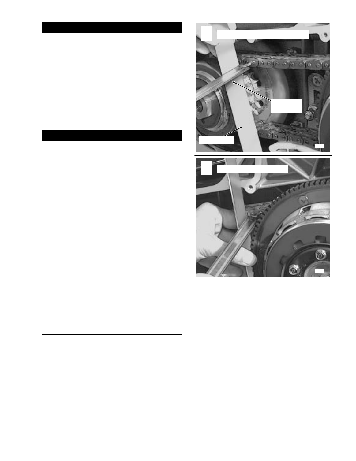
Figure 6-4. Check Sprocket Alignment
Sprocket Alignment (Figure 6-3, 6-4)
The engine compensating sprocket is aligned with the clutch
sprocket by a spacer installed between the alternator rotor
and shaft extension (low output rotor only). Reinstall the
same thickness spacer removed or determine the correct
spacer size as follows:
1. With the primary chaincase cover removed, verify that
the primary chain tension is properly adjusted. See PRI-
MARY CHAIN ADJUSTMENT in this section.
2. At both the engine compensating sprocket and clutch
sprocket sides, push the primary chain inward as far as it
will go.
2004 Touring: Drive 6-5
Page 6

H
OME
3. Place a straightedge vertically across the flanges (cover
gasket surface) near the engine compensating sprocket.
4. Using a dial vernier caliper, measure the distance from
the straightedge to the chain link sideplate. Measure as
close to the engine compensating sprocket as possible
and record the measurement. See A of Figure 6-4.
5. Repeat the measurement on the clutch sprocket side.
See B of Figure 6-4.
For proper primary chain alignment, the difference
between the two measurements must not exceed 0.030
inch (0.76 mm). If the measurement is not within specification, install the appropriate variable thickness spacer
on the engine sprocket shaft between the alternator rotor
and shaft extension. See the adjacent table for the various spacer thicknesses.
Table 6-2. Alternator Rotor Spacers
Inches
0.010 0.25 35850-84
0.020 0.51 35851-84
0.030 0.76 35852-84
0.060 1.52 24032-70
0.090 2.29 24033-70
0.120 3.05 24034-70
0.150 3.81 24035-70
0.180 4.57 24036-70
0.210 5.33 24037-70
Millimeters Part Number
ASSEMBLY
See Section 6.5 PRIMARY CHAINCASE, INSTALLATION,
steps 8-31.
6-6 2004 Touring: Drive
Page 7
H
f1440x6x
Rubber
Boot
Jam
Nut
Cable
Adjuster
Cable
End
f1421x6x
Clutch
Cable
Clutch Lever
Bracket
Ferrule
Adjust for 1/16-1/8 inch
(1.6-3.2 mm) gap
between ferrule
and bracket
OME
CLUTCH 6.3
ADJUSTMENT
CAUTION
Perform the clutch adjustment with the motorcycle at
room temperature. The clearance at the adjuster screw
will increase as the power train temperature increases. If
adjuster screw is adjusted while the powertrain is hot,
clearance at push rod bearing could be insufficient with
power train cold and clutch slippage could occur.
Adjust the clutch at the 1000 mile (1600 km) service interval,
and at every 5000 mile (8000 km) service interval thereafter.
NOTE
Also perform adjustment procedure whenever any clutch
components are replaced. Then repeat adjustment after first
500 miles (800 km) of use.
1. Stand motorcycle upright and level.
Figure 6-6. Clutch Cable Adjuster Mechanism
Adjuster
Screw
Locknut
Retaining
Ring
Figure 6-5. Clutch Adjustment
Release
Plate
f1509b6x
Figure 6-7. Adjust Clutch Free Play
2. Using a T27 TORX drive head, remove five screws (with
captive washers) to free clutch inspection cover from primary chaincase cover.
3. See Figure 6-6. Slide rubber boot off cable adjuster.
Holding cable adjuster with 1/2 inch wrench, loosen jam
nut using a 9/16 inch wrench. Back jam nut away from
cable adjuster. Move adjuster toward jam nut to introduce a large amount of free play at hand lever.
4. See Figure 6-5. Loosen locknut on clutch adjuster screw.
To take up all free play in push rods, turn screw inward
(clockwise) until lightly seated.
5. Back out adjuster screw 1/2 to 1 turn. While holding
adjuster screw with an allen wrench, tighten locknut to
72-120
in-lbs
(8-14 Nm).
6. Squeeze clutch lever to maximum limit three times to set
ball and ramp release mechanism.
2004 Touring: Drive 6-7
Page 8
H
OME
7. Turn cable adjuster away from jam nut until slack is eliminated at hand lever. Pull clutch cable ferrule away from
clutch lever bracket to check free play. Turn cable
adjuster as necessary to obtain 1/16 to 1/8 inch (1.6-3.2
mm) free play between end of cable ferrule and clutch
lever bracket, as shown in Figure 6-7.
8. Hold adjuster with 1/2 inch wrench. Using 9/16 inch
wrench, tighten jam nut against cable adjuster. Cover
cable adjuster mechanism with rubber boot.
9. Remove quad ring from groove in primary chaincase
cover. Wipe all lubricant from the quad ring and inspect
for cuts, tears or signs of deterioration. Replace as necessary.
10. Swab all lubricant from the quad ring groove. Install
quad ring in primary chaincase cover with the nubs contacting the ring groove walls.
NOTE
If lubricant is not thoroughly removed from both the quad ring
and groove, compression of the ring during installation of the
clutch inspection cover can cause lubricant to be squeezed
to the outboard side of the ring groove, resulting in some
temporary weepage around the inspection cover.
11. Using a T27 TORX drive head, install five screws (with
captive washers) to secure clutch inspection cover to the
primary chaincase cover. Alternately tighten screws to
84-108
in-lbs
(10-12 Nm) in the pattern shown in Figure
6-1.
REMOVAL/INSTALLATION
To remove the clutch without disassembly, see Section 6.5
PRIMARY CHAINCASE, REMOVAL, steps 1-16.
For installation instructions, see Section 6.5 PRIMARY
CHAINCASE, INSTALLATION, steps 8-31.
NOTE
If only the clutch pack is to be disassembled, see PA RT IAL
DISASSEMBLY below, a procedure that can be performed on
the motorcycle without removing the clutch shell or hub.
For complete disassembly of the clutch, which includes
clutch pack disassembly and bearing replacement, see
COMPLETE DISASSEMBLY.
PARTIAL DISASSEMBLY
CLUTCH PACK ONLY
1. Remove the primary chaincase cover. See Section 6.5
PRIMARY CHAINCASE, REMOVAL, steps 1-8.
2. Remove six bolts to release diaphragm spring retainer
from clutch hub. See Figure 6-9.
3. Remove diaphragm spring retainer, diaphragm spring
and pressure plate from clutch hub.
f1523x6x
Clutch
Shell
Damper
Spring Seat
Figure 6-8. Clutch Pack Stack-Up (Cut-Away View)
4. Remove friction plates, steel plates, damper spring and
damper spring seat from clutch hub.
5. See CLEANING AND INSPECTION in this section.
Damper
Spring
Clutch
Hub
Steel Plate
Narrow
Friction Plate
ASSEMBLY
CLUTCH PACK ONLY
1. Submerge and soak all friction and steel plates in PRIMARY CHAINCASE LUBRICANT for at least five minutes.
2. Install the narrow friction plate on the clutch hub engaging tabs on plate with slots in clutch shell.
3. Install damper spring seat on clutch hub so that it seats
inboard of narrow friction plate.
4. Install damper spring on clutch hub with the concave
side up (facing opposite damper spring seat). See Fig-
ure 6-8.
5. Install a steel plate and then a friction plate on the clutch
hub. Install seven remaining sets in the same manner,
alternating between steel plates and friction plates.
6. Install pressure plate on clutch hub aligning holes in
plate with threaded bosses on hub.
7. Seat diaphragm spring in recess of pressure plate with
the concave side down.
8. Align holes in diaphragm spring retainer with threaded
bosses on clutch hub. Tabs on spring retainer contact
flats on inboard side of bosses.
9. Install six bolts to secure diaphragm spring retainer to
clutch hub. Alternately tighten bolts to 90-110
(10.2-12.4 Nm).
10. Install the primary chaincase cover. See Section 6.5
PRIMARY CHAINCASE, INSTALLATION, steps 20-31.
in-lbs
6-8 2004 Touring: Drive
Page 9
H
OME
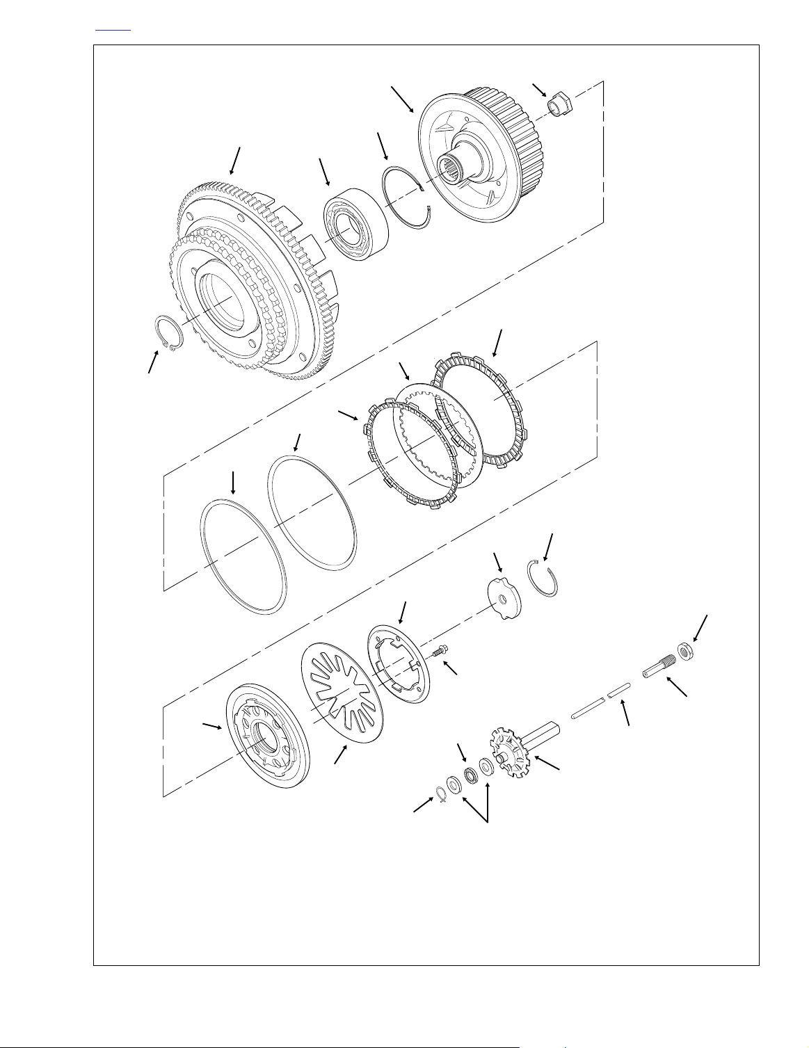
5
6
f1514x6x
4
2
3
7
8
1
9
10
11
12
1. Retaining Ring
2. Clutch Shell
3. Bearing
4. Retaining Ring
5. Clutch Hub
6. Mainshaft Nut
7. Friction Plate (9)
8. Steel Plate (8)
9. Narrow Friction Plate
14
13
24
10. Damper Spring
11. Damper Spring Seat
12. Pressure Plate
13. Diaphragm Spring
14. Diaphragm Spring Retainer
15. Bolt (6)
16. Release Plate
16
15
23
22
17. Retaining Ring
18. Locknut
19. Adjuster Screw
20. Push Rod
21. Oil Slinger
17
18
19
20
21
22. Thrust Washer (2)
23. Throw Out Bearing
24. Retaining Ring
Figure 6-9. Clutch Assembly
2004 Touring: Drive 6-9
Page 10
H
OME
CLEANING AND INSPECTION
1. Wash all parts in cleaning solvent, except for friction
plates and bearing, if removed. Blow dry with compressed air.
Remove retaining ring from clutch hub.
2. Check
friction plates
●
Wipe all lubricant from the friction plates. Measure
as follows:
the thickness of each plate with a dial caliper or
micrometer. If the thickness of any plate is less than
0.143 inch (3.62 mm), discard the friction plates and
replace with an entirely new set.
Look for worn or damaged fiber surface material
●
(both sides).
NOTE
Replace all nine friction plates with an entirely new set if any
individual plate shows evidence of wear or damage.
3. Check
steel plates
Discard any plate that is grooved or bluish in color.
●
as follows:
Blue plates are likely warped or distorted.
●
Check each plate for distortion. Lay the plate on a
precision flat surface. Insert a feeler gauge between
the plate and the flat surface in several places.
Replace any steel plate that is warped more than
0.006 inch (0.15 mm).
4. See Figure 6-9. Holding the clutch hub, rotate the clutch
shell to check bearing for smoothness. Replace the
bearing if it runs rough or binds.
f1519x6x
Press clutch hub from bearing.
5. Check the primary chain sprocket and the starter ring
gear on the clutch shell. Replace the clutch shell if either
sprocket or ring gear are badly worn or damaged.
6. Check the slots that mate with the clutch plates on both
the clutch shell and hub. Replace shell or hub if slots are
worn or damaged.
7. Check the diaphragm spring and diaphragm spring
retainer for cracks or bent tabs. Obtain a new diaphragm
spring or diaphragm spring retainer if either condition
exists.
COMPLETE DISASSEMBLY
CLUTCH PACK AND BEARING
1. Remove clutch assembly from the motorcycle. See Section 6.5 PRIMARY CHAINCASE, REMOVAL, steps 1-16.
2. Remove six bolts to release diaphragm spring retainer
from clutch hub. See Figure 6-9.
3. Remove diaphragm spring retainer, diaphragm spring
and pressure plate from clutch hub.
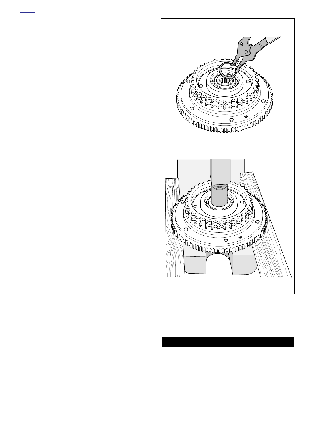
f1522x6x
Figure 6-10. Remove Clutch Hub from Clutch Shell
4. Remove friction plates, steel plates, damper spring and
damper spring seat from clutch hub.
CAUTION
To avoid possible bearing damage, do not disassemble
the clutch shell and hub assembly unless the bearing,
hub or shell require replacement. Replace the bearing if
disassembled.
6-10 2004 Touring: Drive
Page 11

H
1WARNING1WARNING
OME
Remove retaining ring from clutch shell.
Press bearing from clutch shell.
f1521x6x
6. Supporting clutch shell in same orientation, use arbor
press and a suitable press plug to press hub from bearing in clutch shell. See lower frame of Figure 6-10.
7. Turn clutch shell over so that the sprocket side is down.
Remove retaining ring from groove in clutch shell bore.
See upper frame of Figure 6-11.
8. Turn clutch shell over so that sprocket side is up. Using
arbor press and a suitable press plug, press on inner
race to remove bearing from clutch shell bore. See lower
frame of Figure 6-11.
9. See CLEANING AND INSPECTION in this section.
ASSEMBLY
CLUTCH PACK AND BEARING
1. Orient clutch shell in arbor press with sprocket side
down. Be sure to support clutch shell bore on sprocket
side. Using a suitable press plug, press against outer
race until bearing contacts shoulder in clutch shell bore.
Always wear proper eye protection when installing retaining rings. Use the correct retaining ring pliers. Verify
that the tips of the pliers are not damaged or excessively
worn. Slippage may propel the ring with enough force to
cause eye injury.
f1520x6x
Figure 6-11. Remove Bearing from Clutch Shell
1WARNING1WARNING
Always wear proper eye protection when removing retaining rings. Use the correct retaining ring pliers. Verify
that the tips of the pliers are not damaged or excessively
worn. Slippage may propel the ring with enough force to
cause eye injury.
5. With the sprocket side up, remove retaining ring from
clutch hub groove. See upper frame of Figure 6-10.
NOTE
Note that one side of the retaining ring is beveled. Always
install the ring with the beveled side opposite the bearing.
2. Install retaining ring in groove of clutch shell bore, so
that the flat side of the ring is in towards the bearing, the
beveled side out.
3. Center hub in bearing. Be sure that bearing inner race is
supported with sleeve on sprocket side. Press hub into
bearing until hub shoulder contacts bearing inner race.
4. Turn assembly over so that the sprocket side is up.
Install retaining ring in groove of clutch hub.
5. Place clutch assembly on bench oriented with the
sprocket side down.
6. Submerge and soak all friction and steel plates in PRIMARY CHAINCASE LUBRICANT for at least five minutes.
7. Install the narrow friction plate on the clutch hub engaging tabs on plate with slots in clutch shell. See Figure 6-
12.
8. Install damper spring seat on clutch hub so that it seats
inboard of narrow friction plate.
9. Install damper spring on clutch hub with the concave
side up (facing opposite damper spring seat). See Fig-
ure 6-8.
2004 Touring: Drive 6-11
Page 12

H
OME
Narrow Plate
f1513x6x
Regular Plate
Figure 6-12. Friction Plates
10. Install a steel plate and then a friction plate on the clutch
hub. Install seven remaining sets in the same manner,
alternating between steel plates and friction plates.
11. Install pressure plate on clutch hub aligning holes in
plate with threaded bosses on hub.
12. Seat diaphragm spring in recess of pressure plate with
the concave side down.
13. Align holes in diaphragm spring retainer with threaded
bosses on clutch hub. Tabs on spring retainer contact
flats on inboard side of bosses.
14. Install six bolts to secure diaphragm spring retainer to
clutch hub. Alternately tighten bolts to 90-110
in-lbs
(10.2-12.4 Nm).
15. Install clutch assembly on motorcycle. See Section 6.5
PRIMARY CHAINCASE, INSTALLATION, steps 8-31.
6-12 2004 Touring: Drive
Page 13

H
10 lbs. (4.5 kg)
of Force
f1652x6x
See Table 6-3.
Rear Wheel
Sprocket
Transmission
Sprocket
OME
SECONDARY DRIVE BELT AND SPROCKETS 6.4
ADJUSTMENT
1. Remove left side saddlebag. See Section 2.25 SAD-
DLEBAG, REMOVAL.
2. Check deflection at the loosest spot in the belt with the
transmission in neutral and the motorcycle cold. Use
BELT TENSION GAUGE (HD-35381A), or install narro
saddle (HD-35381-3) on existing gauge, and apply 10
lbs. (4.5 kg) of force at the midpoint of the bottom belt
strand. See Figure 6-13. Belt deflection should be as follows:
Table 6-3. Belt Deflection
w
Orientation
Inches Millimeters
On Jiffy Stand
Without Rider or Luggage
10 psi (69 kPa) in Rear Shocks
Motorcycle Upright
With Rear Wheel in the Air
1/4 - 5/16 6.4 - 7.9
3/16 - 1/4 4.8 - 6.4
If belt deflection is within specification, install left side
saddlebag. If adjustment is necessary, proceed to step
3.
3. Remove right side saddlebag. See Section 2.25 SAD-
DLEBAG, REMOVAL.
4. Remove right side muffler as follows:
a. Open worm drive clamps to remove heat shield
from rear header pipe in front of muffler.
Increase
Belt
Deflection
Reduce
Belt
Deflection
Figure 6-13. Check and Adjust Belt Deflection
b. Using a bungee cord, tie the muffler to the lower
saddlebag support rail.
c. Loosen TORCA clamp between rear header pipe
and muffer.
d. Remove two bolts (with lockwashers) to detach muf-
fler from the lower saddlebag support rail.
e. Remove bungee cord to release muffler from lower
saddlebag support rail.
5. Standing on right side of motorcycle, remove E-clip from
groove at end of axle. Loosen cone nut, and then snug
to 15-20 ft-lbs (20-27 Nm). See Figure 6-14.
RIGHT SIDELEFT SIDE
Cone
Nut
Weld
Nub
Weld
Nub
Weld
Nut
8398
E-Clip
8407
Figure 6-14. Move Rear Wheel Forward Until Adjuster Cams Just Contact Weld Nubs
2004 Touring: Drive 6-13
Adjuster
Cam
Page 14

H
OME
6. If belt is too tight, move to step 7 to increase belt deflection. If belt is too loose, reduce belt deflection as
described below:
a. Rotate weld nut on left side of axle in a clockwise
direction.
b. Check belt deflection. Apply 10 lbs. (4.5 kg) of force
at the midpoint of the bottom belt strand. Belt
deflection should be within the range specified in
Ta bl e 6-3.
c. If belt is still too loose, repeat steps 6(a) through
6(b). If belt is now too tight, move to step 7.
7. If belt is too tight, increase belt deflection as follows:
a. Using a hydraulic center stand, raise motorcycle so
that the rear wheel is off the ground.
b. Rotate weld nut on left side of axle in a counter-
clockwise direction.
c. Push wheel forward slightly so that adjuster cam
just contacts weld nub on both sides of rear swingarm. See Figure 6-14.
d. Check belt deflection. Apply 10 lbs. (4.5 kg) of force
at the midpoint of the bottom belt strand. Belt
deflection should be within the range specified in
Ta bl e 6-3.
e. If belt is still too tight, repeat steps 7(b) through 7(d).
If belt is now too loose, move to step 6.
CAUTION
Verify that the exhaust pipes do not contact the vehicle
frame or any mounted components. Contact will cancel
the effect of the rubber isolation mounts and transmit
vibration to the rider via the vehicle frame.
d. Verify that exhaust pipes are in alignment and do
not contact the motorcycle frame or mounted components.
e. Tighten the TORCA clamp to 45-60 ft-lbs (61-81
Nm).
f. Open worm drive clamps and install heat shield on
rear header pipe. Position clamp so that screw is on
the outboard side in the most accessible position.
CAUTION
Verify that the heat shields do not contact the vehicle
frame or any mounted components. Contact will cancel
the effect of the rubber isolation mounts and transmit
vibration to the rider via the vehicle frame.
g. Remove bungee cord from muffler.
12. Install saddlebags. See Section 2.25 SADDLEBAG,
INSTALLATION.
8.
Holding
right side to 95-105 ft-lbs (128.8-142.4 Nm).
If the axle moves during tightening of the cone nut, then the
the belt deflection procedure must be restarted.
9. Recheck belt deflection to verify that it is still within specification.
If the belt deflection is not within specification, loosen
cone nut and then snug to 15-20 ft-lbs (20-27 Nm)
before returning to step 6.
10. With the flat side out, install
side of axle.
11. Install right side muffler as follows:
TORCA muffler clamps have eliminated the need for silicone
or graphite tape during assembly. To ensure sealing integrity
of muffler clamps and prevent the possibility of leakage, Harley-Davidson recommends that TORCA clamp assemblies be
discarded and replaced each time they are removed.
a. Slide
b. Using a bungee cord, tie muffler to lower saddlebag
c. Tighten the two bolts (with lockwashers) to fasten
weld nut on left side of axle, tighten cone nut on
NOTE
new
E-clip in groove on right
NOTE
new
TORCA clamp onto free end of rear
header pipe.
support rail. Install muffler on rear header pipe.
Place TORCA clamp into position between rear
header pipe and muffler.
the muffler to the lower saddlebag support rail.
CLEANING AND INSPECTION
1. Use a spray solution of soap and water to clean belt.
Avoid immersion. Wipe the belt down or blow dry.
Although the belt's urethane compound is resistant to
most solvents, these should only be used on a limited
basis, and then must always be followed by a soap and
water wash.
2. Inspect the edges of the belt for cuts or unusual wear
patterns. While some beveling of the outside edge is
common, and by itself is not usually harmful, it is an indication of sprocket misalignment.
3. Inspect the outside ribbed surface of the belt for signs of
stone puncture. Since it is not always easy to observe
this type of damage, look closely.
4. On the inside of the belt, inspect the roots of the belt
teeth to see if the tensile cords are exposed. See upper
frame of Figure 6-15. The tensile cords are covered by a
layer of nylon facing and another layer of polyethylene.
Once these layers are worn through, the tensile cords
become visible. Visible tensile cords are an indication
that the transmission sprocket tooth tip diameter is
severely worn. Furthermore, belt failure is imminent,
since the tooth tips will continue to scratch away at the
tensile cords until the belt is completely worn through.
NOTE
During initial operation, the thin coating of polyethylene will
wear off as it is burnished into the belt fabric. This is a normal
condition and not an indication of belt wear.
6-14 2004 Touring: Drive
Page 15

H
CAUTION
OME
DRIVE BELT/TRANSMISSION SPROCKET WEAR
Look for
Drive Belt
Tensile Cords
Worn Tooth
Profile
Cracks Here
High-Pressure
Contact Here
5. Look for signs of cracking at the base of the belt teeth
where contact may be made with the “corners” of worn
transmission sprocket teeth. See upper frame of Figure
6-15. Replace the belt if cracking is evident.
Sliding
NOTE
If the belt is replaced for reasons other than stone damage,
the transmission and/or rear wheel sprockets also should be
replaced. Use of worn or damaged sprockets will severely
affect belt service life.
6. For common types of belt wear and damage, see lower
frame of Figure 6-15.
REPLACEMENT
DRIVE BELT WEAR
Internal Tooth Crack
(Hairline)
OK to Run, But Monitor
Missing Teeth
Replace Belt
Fuzzy Edge Cord
(Not Serious)
OK to Run, But Monitor
Transmission
Sprocket
Pack Man Cracks
Replace Belt
Chipping
(Not Serious)
OK to Run, But Monitor
Hook Wear
Replace Belt
f1632x6x
f1651x6x
Removal
1. Remove rear wheel and rear swingarm. See Section
2.20 REAR SWINGARM, REMOVAL.
2. Remove the primary chaincase assembly. See Section
6.5 PRIMARY CHAINCASE, REMOVAL.
3. Remove the old belt from the transmission sprocket.
Installation
Handle the drive belt with care. Never bend belt forward
into a loop smaller than five inches (127 mm) diameter.
Never bend belt into a reverse loop smaller than ten
inches (254 mm) diameter. Over bending will weaken belt
and result in premature failure. Always install belt in the
same direction of rotation as when it was removed. For
other handling tips, see Figure 6-16.
1. Install the
2. Install the primary chaincase assembly. See Section 6.5
PRIMARY CHAINCASE, INSTALLATION.
3. Install rear swingarm and rear wheel. Adjust belt deflection. See Section 2.20 REAR SWINGARM, INSTALLA-
TION.
new
belt on the transmission sprocket.
Cross-Sectional View
Stone Damage
Replace Belt
if Damage on Edge
Bevel Wear
(Outboard Edge Only)
OK to Run, But Monitor
Figure 6-15. Drive Belt/Transmission Sprocket Wear
TRANSMISSION SPROCKET
Removal
1. Remove rear wheel. See Section 2.4 REAR WHEEL,
REMOVAL.
2. Remove the primary chaincase assembly. See Section
6.5 PRIMARY CHAINCASE, REMOVAL.
2004 Touring: Drive 6-15
Page 16

H
OME
Forward bend must not be less than 5 in. (127 mm). Reverse bend must not be less than 10 in. (254 mm).
Minimum Diameter
Do not twist. Do not crimp, pinch or kink.
AB
Minimum Diameter
CD
CAUTION
Mishandling drive belt will result in premature failure.
For maximum strength, integrity and longevity, avoid
over bending (A and B), twisting (C), crimping, pinching or kinking (D), and prying (E).
Figure 6-16. Proper Drive Belt Handling
3. See Figure 6-17. Remove the two socket screws and
lockplate to free the sprocket nut.
NOTE
The transmission sprocket nut has left handed threads. Turn
the nut clockwise to remove from the main drive gear.
4. Remove the sprocket nut. Use an air impact wrench for
best results.
Cleaning and Inspection
1. Using a non-volatile cleaning solvent, thoroughly clean
the transmission sprocket of all grease and dirt.
2. Carefully inspect the sprocket for cracks or other damage.
Do not pry.
3. Inspect the sprocket for heavy pitting, which indicates a
high degree of abrasive wear.
4. Look for “sharp” corners at the top of each sprocket
tooth, particularly where the flank joins the top radius. A
smooth transition should exist between the flank and
radius. While worn teeth will appear to have an edge
across the face width of the tooth, heavily worn teeth will
have a flat across the top. If the flat is 1/8 inch (3 mm)
wide or more, replace the transmission sprocket and
drive belt. See upper frame of Figure 6-15.
E
Installation
1. Install the transmission sprocket (with belt) on the main
drive gear.
6-16 2004 Touring: Drive
Page 17

H
f1855x7x
f1856x7x
Sprocket
Locking Tool
Transmission
Sprocket
Sprocket
Locking Tool
Sprocket
Nut
Pivot Shaft
OME
Main Drive
Gear
Mainshaft
Oil Seal
Spacer
Sleeve
Lockplate
Sprocket
Nut
Quad Seal
Transmission
Sprocket
f1172a6x
Lubricate
Contact Surfaces
Socket
Screw
Figure 6-17. Transmission Sprocket Components
2. To install the sprocket nut, follow the appropriate procedure based on whether a new or used nut is being
installed.
CAUTION
Exercise caution to avoid getting oil on the threads of
the sprocket nut or the integrity of the lock patch may be
compromised.
New sprocket nut:
smear a small quantity of clean
engine oil on the inside face of both the sprocket nut and
the sprocket. Limit the application to where the surfaces
of the two parts contact each other. Install the sprocket
nut until finger tight.
NOTE
The transmission sprocket nut has left handed threads. Turn
the nut counterclockwise to install.
Used sprocket nut:
apply Loctite High Strength Threadlocker 262 (red) to the threads of the sprocket nut. Also
smear a small quantity of Loctite or clean engine oil on
the inside face of both the sprocket nut and the sprocket.
Limit the application to where the surfaces of the two
parts contact each other. Install the sprocket nut until finger tight.
3. Lock transmission sprocket with the FINAL DRIVE
SPROCKET LOCKING TOOL (Part No. HD-41184). See
Figure 6-18.
Insert handle of tool below pivot shaft inboard of bottom
frame tube and attach to sprocket. Snug thumbscrew to
lock position of tool on sprocket. See Figure 6-19.
4. Install pilot of MAINSHAFT LOCKNUT WRENCH (Part
No. HD-94660-37B) on threaded end of mainshaft. See
Figure 6-20. Slide sleeve of locknut wrench over pilot
and onto sprocket nut. Tighten sprocket nut to 60 ft-lbs
(81 Nm). As the nut is tightened the handle of the
sprocket locking tool rises to contact the pivot shaft,
thereby preventing sprocket/mainshaft rotation. See Fig-
ure 6-21.
Figure 6-18. Final Drive Sprocket Locking Tool
(Part No. HD-41184)
Figure 6-19. Install Final Drive Sprocket Locking Tool
5. Scribe a straight line on the transmission sprocket nut
continuing the line over onto the transmission sprocket
as shown in Figure 6-22. Tighten the transmission
sprocket nut an additional 35° to 40°.
2004 Touring: Drive 6-17
Page 18

H
OME
Wrench
7. If holes in lockplate do not align with those in sprocket,
tighten sprocket nut as necessary (up to the 45° maximum) until sprocket and lockplate holes are in alignment. See Figure 6-22.
CAUTION
Figure 6-20. Mainshaft Locknut Wrench/Pilot
(Part No. HD-94660-37B )
Sprocket
Nut
Pilot
Mainshaft
Locknut
Wrench
Pilot
f1857x7x
f1858x7x
Maximum allowable tightening of sprocket nut is 45° of
counterclockwise rotation after a torque of 60 ft-lbs (81
Nm). Do not loosen sprocket nut to align holes or nut will
be under tightened.
8. Insert two socket head screws through lockplate into
sprocket holes. Tighten screws to 90-110
in-lbs
(10-12
Nm).
NOTE
The socket head screws have a thread locking compound
that allows them to be reused up to three times. The fourth
time the screws are removed, replace with
new
screws (H-D
Part No. 3594).
9. Install primary chaincase assembly. See Section 6.5
PRIMARY CHAINCASE, INSTALLATION.
10. Install rear wheel and adjust belt deflection. See Section
2.4 REAR WHEEL, INSTALLATION.
REAR WHEEL SPROCKET
Removal
1. Remove rear wheel. See Section 2.4 REAR WHEEL,
REMOVAL.
2. Remove five bolts with flat washers securing sprocket to
hub.
Torque
Wrench
Figure 6-21. Install Mainshaft Locknut Pilot/Wrench
and Torque Sprocket Nut
6. Install lockplate over nut so that two diagonally opposite
holes align with two tapped holes in sprocket. To find the
best fit, lockplate can be rotated to a number of positions
and can be placed with either side facing sprocket.
6-18 2004 Touring: Drive
Sprocket Nut
Transmission
Sprocket
Scribe Line
on Nut and Sprocket
Figure 6-22. Tighten/Secure Sprocket Nut
f1977x6x
45°
35°
Page 19

H
OME
Cleaning and Inspection
1. Using a non-volatile cleaning solvent, thoroughly clean
the rear wheel sprocket of all grease and dirt.
2. Carefully inspect the sprocket for cracks or other damage.
3. Inspect each sprocket tooth for large chrome chips having sharp edges. Look for gouges caused by contact
with a hard object. If large enough, both of these conditions will leave a corresponding pattern in the belt face
and are cause for rear sprocket replacement.
4. Without obvious damage, rear wheel sprocket replacement may be a subjective decision based on general
appearance. Using medium pressure, drag a scribe or
the sharp point of a knife blade across the root of a
groove. Even though the plating is lightest in the root
area, a knife point should not penetrate the chrome. If
the blade slides across the chrome plating without digging in, then the chrome is still good. On the other hand,
if you can feel the scribe digging in and it leaves a visible
mark, then the chrome plating has worn off and the bare
aluminum is being cut. Loss of chrome is cause for rear
sprocket replacement.
Installation
1. Apply two drops of Loctite High Strength Threadlocker
271 (red) to threads of each of five sprocket bolts.
Secure sprocket to hub using bolts with flat washers
(and locknuts on laced wheels). Tighten bolts to
55-65 ft-lbs (75-88 Nm).
2. Install rear wheel and adjust belt deflection. See Section
2.4 REAR WHEEL, INSTALLATION.
2004 Touring: Drive 6-19
Page 20

H
OME
PRIMARY CHAINCASE 6.5
GENERAL
The primary chaincase is a sealed housing containing the
primary chain, clutch, engine compensating sprocket, chain
tensioner assembly, alternator and starter drive mechanism.
LUBRICATION
At the 1000 mile (1600 km) service interval, and at every
5000 mile (8000 km) service interval thereafter, change the
primary chaincase lubricant as follows:
1. Using a T27 TORX drive head, remove five screws (with
captive washers) to free clutch inspection cover from primary chaincase cover.
2. Remove magnetic drain plug at bottom of primary chaincase cover. Drain lubricant into suitable container. See
Figure 6-23.
3. Clean drain plug. If plug has accumulated a lot of debris,
inspect the condition of chaincase components.
4. Inspect drain plug O-ring for cuts, tears or signs of deterioration. Replace as necessary.
5. Install drain plug back into primary chaincase cover.
Tighten plug to 36-60
6. Pour 32 ounces (946 ml) of Harley-Davidson PRIMARY
CHAINCASE LUBRICANT through the clutch inspection
cover opening, Part No. 99887-84 (quart) or Part No.
99886-84 (gallon). See Figure 6-24.
f1210x6x
4
Primary
Chain
Inspection
Cover
in-lbs
1
32
(4.1-6.8 Nm).
1
Clutch
43
Inspection
Cover
2
5
Primary
Chaincase Cover
Lubricant
f1508b6x
Figure 6-24. Fill Primary Chaincase With Lubricant
CAUTION
Do not overfill the primary chaincase with lubricant.
Overfilling may cause rough clutch engagement, incomplete disengagement, clutch drag and/or difficulty in
finding neutral at engine idle.
7. Remove quad ring from groove in primary chaincase
cover. Wipe all lubricant from the quad ring and inspect
for cuts, tears or signs of deterioration. Replace as necessary.
8. Swab all lubricant from the quad ring groove. Install
quad ring in primary chaincase cover with the nubs contacting the ring groove walls.
NOTE
If lubricant is not thoroughly removed from both the quad ring
and groove, compression of the ring during installation of the
clutch inspection cover can cause lubricant to be squeezed
to the outboard side of the ring groove, resulting in some
temporary weepage around the inspection cover.
9. Using a T27 TORX drive head, install five screws (with
captive washers) to secure clutch inspection cover to the
primary chaincase cover. Alternately tighten screws to
84-108
in-lbs
(10-12 Nm) in the pattern shown in Figure
6-23.
Figure 6-23. Primary Chaincase Cover
6-20 2004 Touring: Drive
Drain Plug
REMOVAL
1. Remove seat. See Section 2.24 SEAT, REMOVAL.
Page 21

H
1WARNING1WARNING
OME
f1840x6x
Top Center Nut
Primary
Chain
Adjuster
Shoe
Figure 6-25. Chain Tensioner Assembly
1WARNING1WARNING
To protect against shock and accidental start-up of vehicle, disconnect the negative battery cable before proceeding. Inadequate safety precautions could result in
death or serious injury.
2. Unthread bolt and remove battery negative cable (black)
from battery negative (-) terminal.
3. Standing on left side of motorcycle, remove magnetic
drain plug at bottom of primary chaincase cover. Drain
lubricant into suitable container.
NOTE
If drain plug has accumulated a lot of debris, inspect the condition of chaincase components.
4. Remove socket screw with lockwasher to remove passenger footboard from rear swingarm bracket.
5. Remove socket screw (with lockwasher and flat washer)
to release front footboard forward bracket from frame
weldment. For best results, approach from opposite side
using a 3/8 inch ball allen with extension. To free front
footboard rear bracket from frame weldment and jiffy
stand bracket, remove lower hex bolt (with lockwasher)
and upper hex bolt (with lockwasher and locknut).
6. Remove locknut, lockwasher and flat washer to free
shifter rod from front inboard shifter lever.
7. Remove socket head screws and pull both toe and heel
shifter levers from shifter shaft. Remove rubber spacer. If
preferable, remove socket head screw to release front
inboard shifter lever instead, and then pull shifter shaft/
lever assembly from primary chaincase bore. When pulling any lever from splined shaft, always mark splines on
both shaft and lever to assist in assembly.
8. Remove ten allen head socket screws (with captive
washers) from primary chaincase cover. Remove primary chaincase cover from motorcycle.
9. Loosen top center nut from captured bolt of chain tensioner assembly. See Figure 6-25. Lower the chain tensioner assembly as required, so that the adjuster shoe
rests flat on casting of primary chaincase.
Always wear proper eye protection when removing retaining rings. Use the correct retaining ring pliers. Verify
that the tips of the pliers are not damaged or excessively
worn. Slippage may propel the ring with enough force to
cause eye injury.
10. Remove retaining ring and pull release plate (with locknut and adjuster screw) from clutch hub. See Figure 6-
26.
11. Obtain the PRIMARY DRIVE LOCKING TOOL (HD-
41214). See Figure 6-27.
With the flat side against the upper strand of the primary
chain, insert stepped side of tool into teeth of engine
compensating sprocket. Using a breaker bar and 1-1/2
inch socket, turn the sprocket nut in a counterclockwise
direction. Once the stepped area of the tool is drawn into
the sprocket, rotation of the primary drive is stopped.
Continue turning sprocket nut until loose. See Figure 6-
28.
Adjuster
Screw
Locknut
Release
Retaining
Ring
Figure 6-26. Clutch Hub Release Plate Assembly
Plate
f1509b6x
2004 Touring: Drive 6-21
Page 22

H
OME
NOTE
If too much loctite, or perhaps the wrong loctite, was used to
install the engine compensating sprocket nut, it may be very
difficult to remove. In these cases, break down loctite using
heat from a small propane torch. Apply heat evenly around
nut head in a circular motion, but not for so long as to turn nut
blue. Do not direct heat at chain tensioner assembly and
other components or damage will result. If unable to loosen
sprocket nut with breaker bar after applying heat, use air
impact wrench as the last alternative.
1WARNING1WARNING
Use extreme caution when operating propane torch.
Read the manufacturers instructions carefully before
use. Do not direct open flame or heat toward any fuel
system component. Extreme heat can cause fuel ignition
and explosion. Inadequate safety precautions could
result in death or serious injury.
12. Reverse the position of the primary drive locking tool.
With the flat side against the upper strand of the primary
chain, insert stepped side of tool into teeth of clutch
sprocket. Using a breaker bar and 1-3/16 inch socket,
turn the clutch hub mainshaft nut in a cloc
until loose. See Figure 6-30.
Do not place the tool on the
lower strand of the primary
chain. Rotation of either the compensating sprocket nut or clutch
hub nut causes tool to exert
enough force to break or shatter
the nylon adjuster shoe.
Figure 6-27. Primary Drive Locking Tool
(Part No. HD-41214)
kwise direction
CAUTION
Alternator Rotor Spacer
Low Output Rotor Only - 0.020 In.
f1208axx
Compensating
Sprocket
Sprocket
Cover
Shaft
Extension
Sliding
Cam
Compensating
Sprocket Nut
Figure 6-29. Engine Compensating Sprocket Assembly
NOTE
Clutch hub mainshaft nut has left handed threads.
13. Remove the primary drive locking tool. Remove the
clutch hub mainshaft nut and engine compensating
sprocket nut.
14. Remove sprocket cover and sliding cam. See Figure 6-
29.
15. Remove clutch, primary chain, compensating sprocket
and shaft extension as a single assembly. See Figure 6-
31.
16. Remove the alternator rotor spacer from the engine
sprocket shaft, if present.
NOTE
The alternator rotor spacer is only present on those vehicles
with the 38 amp low output rotor.
7859
Primary Drive
Locking Tool
Breaker
Bar
Figure 6-28. Place Primary Drive Locking Tool
and Loosen Compensating Sprocket Nut
6-22 2004 Touring: Drive
7856
Primary Drive
Locking Tool
Breaker
Bar
Figure 6-30. Place Primary Drive Locking Tool
and Loosen Clutch Hub Mainshaft Nut
Page 23

H
1WARNING1WARNING
CAUTION
1WARNING1WARNING
OME
Compensating
Sprocket
7943
coatings into the steel backing). Replace the lip seal.
See STARTER JACKSHAFT BUSHING AND LIP SEAL
- PRIMARY CHAINCASE in this section.
4. Check the shifter bracket bushings in the primary chaincase. Replace the bushings if necessary. See SHIFTER
BRACKET BUSHINGS in this section.
Primary
Chain
Shaft
Extension
Figure 6-31. Remove Clutch Assembly, Primary Chain,
Compensating Sprocket and Shaft Extension
17. Bend tab on lockplate away from head of jackshaft bolt.
Holding pinion gear to prevent rotation, remove the jackshaft bolt with lockplate and thrust washer. Carefully pull
jackshaft assembly from primary chaincase bore.
18. From right side of motorcycle, remove starter front
mounting screw with lockwasher. Remove rear mounting
screw with lockwasher, but do not disconnect chassis
ground cable ring terminal.
19. Returning to left side of motorcycle, remove two bolts
(with flat washers) from outside edge of primary chaincase.
20. Using a chisel and hammer, bend tabs on lockplates
away from heads of 5 inside bolts. Remove bolts (with
lockplates) to free primary chaincase from crankcase
and transmission housings. Remove primary chaincase
from motorcycle.
21. Remove O-ring from crankcase lip and discard.
Clutch
Assembly
INSPECTION AND REPAIR
1. Inspect the primary chaincase for cracks or other damage. Replace as necessary.
2. Check the mainshaft bearing. Bearing must rotate freely
without drag. Replace the bearing if necessary. Replace
the lip seal. See MAINSHAFT BEARING AND LIP SEAL
on this page.
NOTE
Also check the bearing inner race on the mainshaft. Replace
the race if scored or excessively worn. See MAINSHAFT
BEARING INNER RACE in this section.
3. Check the starter jackshaft bushing in the primary chain-
case. Check the jackshaft bushing in the primary chaincase cover. Replace the bushings if they are damaged
or excessively worn (i.e., through the teflon and copper
DISASSEMBLY
MAINSHAFT BEARING AND LIP SEAL
REMOVAL
Always wear proper eye protection when removing retaining rings. Use the correct retaining ring pliers. Verify
that the tips of the pliers are not damaged or excessively
worn. Slippage may propel the ring with enough force to
cause eye injury.
1. Remove retaining ring from groove on clutch side of primary chaincase. Turn the chaincase over to transmission side.
2. Pull lip seal from bearing bore on transmission side of
primary chaincase. Use a seal remover or rolling head
pry bar for best results. Remove retaining ring from
groove on same side of chaincase.
Failure to provide proper support will cause the casting
to crack or break around the outside diameter of the
boss. Any damage to the casting requires replacement
of the primary chaincase.
3. Place primary chaincase in arbor press with the transmission side up. Be sure to properly support boss on
clutch side to avoid damage to casting.
4. Center bearing under ram, and using a suitable driver,
carefully press out bearing applying pressure to the
outer race.
INSTALLATION
1. Inspect the bearing bore to verify that it is clean and
smooth.
Always wear proper eye protection when installing retaining rings. Use the correct retaining ring pliers. Verify
that the tips of the pliers are not damaged or excessively
worn. Slippage may propel the ring with enough force to
cause eye injury.
2004 Touring: Drive 6-23
Page 24

H
OME
f1216x6x
Figure 6-32. Mainshaft Bearing Inner Race Remover
(Part No. HD-34902B)
f1217x7x
Bearing
Inner Race
Mainshaft
Plug
Bridge
4. Place primary chaincase in arbor press with the clutch
side up. Be sure to properly support boss on transmission side to avoid damage to casting.
5. Place bearing over bore with the lettered side up. Center
bearing under ram, and using a suitable driver, apply
pressure to the outer race until bearing makes contact
with the installed retaining ring.
6. Install second retaining ring to lock position of bearing in
bore on clutch side of chaincase. Verify that retaining
ring is fully seated in the groove.
7. Turn chaincase over, so that the transmission side is up.
With the open (lip garter spring) side facing the bearing,
press fit a new lip seal into the bore until it makes contact with the installed retaining ring. Be sure to support
bearing outer race on clutch side during the press procedure. Verify that seal is square in the bore and completely seated around its circumference.
8. Lubricate the bearing and lip seal with multi-purpose
grease or clean H-D 20W50 engine oil.
MAINSHAFT BEARING INNER RACE
NOTE
The bearing inner race must be properly positioned on the
mainshaft to align with the bearing outer race in the primary
chaincase. To remove and install the bearing inner race, use
the combination MAINSHAFT BEARING INNER RACE
REMOVER/INSTALLER, Part No. HD-34902B. See Figure 632 and Figure 6-34.
Puller
Plate
Long
Bolt
Flat
Washer
Forcing
Screw
Figure 6-33. Pull Mainshaft Bearing Inner Race
2. Install retaining ring in groove on transmission side of
primary chaincase. Verify that the retaining ring is fully
seated in the groove.
3. Apply a thin film of clean H-D 20W50 engine oil to bearing bore and O.D. of new bearing.
CAUTION
Failure to provide proper support will cause the casting
to crack or break around the outside diameter of the
boss. Any damage to the casting requires replacement
of the primary chaincase.
REMOVAL
1. Install small flat washers on two long bolts of puller tool.
Slide one bolt into channel on each side of bridge so that
washer is between bridge and bolt head. Thread bolts
into stamped side of U-shaped puller plate an equal
number of turns.
2. Sparingly apply graphite lubricant to threads of forcing
screw to ensure smooth operation. Thread forcing screw
into center hole of bridge.
3. Position U-shaped puller plate between bearing inner
race and sprocket nut. See Figure 6-33.
4. Install mainshaft plug into end of transmission mainshaft. Thread the forcing screw into the bridge until the
steel ball at the end of the screw seats in the cavity of
the mainshaft plug. Verify that the tool assembly is
square so that the bearing is not cocked during removal.
5. Continue turning the forcing screw until the bearing inner
race is pulled free of the mainshaft.
INSTALLATION
1. See Figure 6-35. Chamfered edge first, slide the bearing
inner race onto the transmission mainshaft.
2. Thread extension shaft onto end of mainshaft.
6-24 2004 Touring: Drive
Page 25

H
OME
f1215x6x
Figure 6-34. Mainshaft Bearing Inner Race Installer
(Part No. HD-34902B)
Install Inner Race
and Extension Shaft
Extension
Shaft
Wrench
Flat
NOTE
Extension shaft has left handed threads, so turn counterclockwise to install.
3. See Figure 6-35. Slide installer tube over extension shaft
until it contacts bearing inner race. Sparingly apply
graphite lubricant to threads of extension shaft to ensure
smooth operation.
4. Place both large flat washers over threaded portion of
extension shaft until they contact installer tube. Install
large hex nut onto extension shaft.
5. With a wrench on flats at threaded end of extension
shaft, hold shaft stationary while turning hex nut in a
clockwise direction. In this manner, press race onto shaft
so inside edge is 0.100 in. (2.54 mm) from main drive
gear.
6. Lubricate the race with multi-purpose grease or clean
engine oil.
STARTER JACKSHAFT BUSHING AND LIP SEAL - PRIMARY CHAINCASE
REMOVAL
1. Remove bushing from jackshaft bore of primary chain-
case. For best results, use a bushing/bearing puller with
expandable collet and slide hammer.
2. Remove lip seal from bore.
Bearing
Inner Race
Install Tube, Flat Washers
and Hex Nut
Flat
Washers
Installer
Tube
f1218x7x
Figure 6-35. Press Bearing Inner Race onto Mainshaft
Hex
Nut
INSTALLATION
1. Inspect the bushing bore to verify that it is clean and
smooth. Place primary chaincase in arbor press with the
clutch side up. Support forward part of case so that it lies
flat on transmission mounting flanges.
2. With the open (lip garter spring) side facing up, press fit
a new lip seal into the jackshaft bore until it makes solid
contact with the shoulder on the transmission side. Verify
that the seal is square in the bore and completely seated
around its circumference.
3. See Figure 6-36. Press new bushing into bore. Bushing
must be flush with boss or at a depth not exceeding
0.010 in. (0.76 mm).
4. Lubricate the bushing and seal lip with multi-purpose
grease or clean engine oil.
STARTER JACKSHAFT BUSHING PRIMARY CHAINCASE COVER
REMOVAL
1. Remove bushing from jackshaft bore of primary chain-
case cover. For best results, use a bushing/bearing
puller with expandable collet and slide hammer.
2. Inspect the bushing bore to verify that it is clean and
smooth.
2004 Touring: Drive 6-25
Page 26

H
OME
f1212a6x
Primary
Chaincase
Press Bushing Flush
With Boss or to a
Maximum Depth of
0.010 In. (0.25 mm)
Bushing
Lip Seal
Press Lip Seal
Transmission
Against Shoulder
Side
Figure 6-36. Install Jackshaft Seal and Bushing in
Primary Chaincase
INSTALLATION
1. Using a T27 TORX drive head, remove five screws (with
captive washers) to free clutch inspection cover from primary chaincase cover.
SHIFTER BRACKET BUSHINGS
REMOVAL
1. Remove spacer and shifter shaft assembly from shifter
bracket bore of primary chaincase.
2. Using an arbor press, press bushings from bore. Inspect
the bushing bore to verify that it is clean and smooth.
INSTALLATION
1. Place primary chaincase in arbor press.
2. Press new bushing into each end of bore. Installed
bushings must be flush to 0.010 inch (0.76 mm) above
outer edge of bore.
3. Install shifter shaft in shifter bracket bore. Install spacer
on shifter shaft.
4. Assemble primary chaincase. See Section 6.5 PRI-
MARY CHAINCASE, INSTALLATION, on the next page.
2. Place primary chaincase cover in arbor press. Support
forward part of case so that it lies flat around the clutch
inspection cover bore.
3. Press new bushing into bore. Bushing must be flush with
boss or at a depth not exceeding 0.010 in. (0.76 mm).
4. Lubricate the bushing with multi-purpose grease or
clean engine oil.
6-26 2004 Touring: Drive
Page 27

H
CAUTION
OME
11
17
14
7
1. Magnetic drain plug and O-ring
2. Primary chaincase cover
3. Bolt (3), 5/16-18 x 3 in.
4. Hole
5. Lockplate (5)
6. Bolt (4), 5/16-18 x 1-3/4 in.
7. Primary chaincase
8. Lip seal
9. Retaining ring (2)
10. Bearing, mainshaft
11. Lip seal
12. Bushing
13. Bushing
14. Bushing (2)
14
25
5
6
18
12
5
3
3
4
5
25
19
6
19
15. Primary chain inspection cover
16. Quad ring
17. O-ring
18. Dowel pin (2)
19. Gasket
20. Screw, cover (5)
22
8
13
9
10
9
2
21
16
1
15
21. Screw, cover (5)
22. Gasket
23. Screw (4)
24. Screw (5)
25. Washer (2)
26. Clutch inspection cover
f1048x6x
20
26
24
23
Figure 6-37. Primary Chaincase Assembly
INSTALLATION
1. Install new O-ring on lip of crankcase.
CAUTION
Failure to apply silicone sealer to the bolts and bolt
holes on the inboard side of the primary chaincase may
result in oil leakage after assembly.
2. On the crankcase/transmission side of the primary
chaincase, apply RTV silicone sealer to the following
areas:
● Around the two rear primary chaincase to crank-
case bolt holes. See B in left frame of Figure 6-38.
● Around the three primary chaincase to transmission
bolt holes. See right frame of Figure 6-38.
Also apply the silicone sealer to the threads of the five
fasteners installed in these holes.
The mainshaft splines may damage the sealing surface
of the lip seal if the protector sleeve is not used.
3. Place the seal protector sleeve (from the MAIN DRIVE
GEAR SEAL INSTALLER, HD-41405) over the mainshaft splines. Lightly lubricate the sleeve with clean
engine oil.
4. Place the primary chaincase into position against the
crankcase and transmission housings. Remove the seal
protector sleeve from the mainshaft.
5. See A in left frame of Figure 6-38. Start two forward
bolts (1-3/4 inches with flat washers) to fasten outside
edge of primary chaincase to front of crankcase.
2004 Touring: Drive 6-27
Page 28

H
OME
Start four 1-3/4 inch bolts to engine. Start three 3 inch bolts to transmission.
7948
3
2
With Lockplate
A
With Flat Washer
With Lockplate
B
4
1
Figure 6-38. Primary Chaincase Screw Size and Torque Sequence
See B in left frame of Figure 6-38. From within the primary chaincase, start two forward bolts (1-3/4 inches
with lockplates) to fasten primary chaincase to rear of
crankcase.
See right frame of Figure 6-38. From within the primary
chaincase, start three rearward bolts (3 inches with lockplates) to fasten primary chaincase to front and rear of
transmission.
Tighten the seven bolts to 18-21 ft-lbs (24-28 Nm) in the
numerical sequence shown in Figure 6-38.
Bend one tab on each lockplate against the flat of the
bolt head to secure.
6. On right side of motorcycle, install the front starter
mounting screw with lockwasher. Install rear mounting
screw and lockwasher (with chassis ground cable ring
terminal). Alternately tighten front and rear starter
mounting screws to 13-20 ft-lbs (18-27 Nm).
With Lockplate
7
5
6
7946
8. Install alternator rotor spacer on engine sprocket shaft, if
present. See Figure 6-29.
NOTE
The alternator rotor spacer is only present on those vehicles
with the 38 amp low output rotor.
9. Install the clutch, primary chain, compensating sprocket
and shaft extension as a single assembly. See Figure 6-
31. Start clutch assembly on the mainshaft, while plac-
ing the shaft extension on the engine sprocket shaft. The
clutch hub and shaft extension are splined, so a slight
rotation of the chain drive will aid in lining up the splines.
10. Place sliding cam over shaft extension. Slide sprocket
cover over sliding cam. See Figure 6-29.
11. Apply two drops of Loctite High Strength Threadlocker
262 (red) to the threads of the engine compensating
sprocket nut. Install nut and hand tighten in a clockwise
direction.
7. Returning to left side of motorcycle, gently insert jackshaft assembly into primary chaincase so that splined
end of shaft engages coupling on starter output shaft.
Insert key on lockplate through slot in thrust washer and
into keyway on jackshaft. Thread the jackshaft bolt into
the starter shaft making sure that the lockplate key
remains in the keyway. Holding pinion gear to prevent
rotation, tighten jackshaft bolt to 60-80 in-lbs (6.8-9.0
Nm). Bend tab on lockplate against flat of bolt head to
secure.
6-28 2004 Touring: Drive
12. Apply two drops of Loctite High Strength Threadlocker
262 (red) to the threads of the clutch hub mainshaft nut.
Install nut and hand tighten in a counter
clockwise
direction.
NOTE
Clutch hub mainshaft nut has left handed threads.
13. Obtain the PRIMARY DRIVE LOCKING TOOL (HD-
41214). See Figure 6-39.
Page 29

H
1WARNING1WARNING
7858
Primary Drive
Locking Tool
Torque
Wrench
OME
With the flat side against the upper strand of the primary
chain, insert stepped side of tool into teeth of clutch
sprocket. Verify that adjuster shoe of chain tensioner
assembly rests fl
at on casting of primary chaincase, and
then using a torque wrench and 1-1/2 inch socket,
tighten sprocket nut to 150-165 ft-lbs (203-224 Nm). See
Figure 6-40.
NOTE
Once the stepped area of the tool is drawn into the sprocket,
rotation of the primary drive is stopped.
14. Reverse the position of the primary drive locking tool.
With the flat side against the upper strand of the primary
chain, insert stepped side of tool into teeth of engine
compensating sprocket. Using a torque wrench and 1-3/
16 inch socket, tighten clutch hub mainshaft nut to 70-80
ft-lbs (95-108 Nm). See Figure 6-41.
15. Remove the primary drive locking tool.
16. Install release plate (with locknut and adjuster screw)
into clutch hub bore. The word “OUT” is stamped on the
release plate to indicate the outboard side.
CAUTION
Do not place the tool on the
lower strand of the primary
chain. Rotation of either the compensating sprocket nut or clutch
hub nut causes tool to exert
enough force to break or shatter
the nylon adjuster shoe.
Figure 6-39. Primary Drive Locking Tool
(Part No. HD-41214)
Always wear proper eye protection when installing retaining rings. Use the correct retaining ring pliers. Verify
that the tips of the pliers are not damaged or excessively
worn. Slippage may propel the ring with enough force to
cause eye injury.
17. Install retaining ring in clutch hub bore to lock release
plate in position. Verify that the retaining ring is completely seated in the groove.
18. Adjust clutch. See Section 6.3 CLUTCH, ADJUST-
MENT, steps 3-8.
19. Adjust primary chain tension. See Section 6.2 PRIMARY
CHAIN AND SPROCKETS, PRIMARY CHAIN ADJUSTMENT, steps 2-4.
20. Remove old gasket from flange of primary chaincase
and discard. Thoroughly clean gasket surface. Hang
new gasket on dowels.
21. Start ten allen head socket screws (five long, five short)
with flat washers to install primary chaincase cover.
Tighten screws to 84-108 in-lbs (9-12 Nm) in the numer-
ical sequence shown in Figure 6-42.
22. Clean magnetic drain plug and inspect O-ring for cuts,
tears or signs of deterioration. Replace O-ring as necessary. Install drain plug back into primary chaincase cover
and tighten to 36-60 in-lbs (4.1-6.8 Nm).
23. Using a T27 TORX drive head, remove five screws (with
captive washers) to free clutch inspection cover from primary chaincase cover, if installed.
Primary Drive
Locking Tool
Torque
Wrench
Figure 6-40. Place Primary Drive Locking Tool
and Torque Compensating Sprocket Nut
7857
Figure 6-41. Place Primary Drive Locking Tool
and Torque Clutch Hub Mainshaft Nut
2004 Touring: Drive 6-29
Page 30

H
OME
S = Short Screw, 1-1/4 In.
f1210x6x
L = Long Screw, 1-1/2 In.
S
L
2
S
6
S
4
Primary
Chain
Inspection
Cover
8
Clutch
Inspection
Cover
L
10
9
5
3
S
S
Figure 6-42. Primary Chaincase Cover Torque Sequence
and Screw Size
Primary
Chaincase Cover
Drain
1
Plug
L
L
7
L
CAUTION
Do not overfill the primary chaincase with lubricant.
Overfilling may cause rough clutch engagement, incomplete disengagement, clutch drag and/or difficulty in
finding neutral at engine idle.
25. Remove quad ring from groove in primary chaincase
cover. Wipe all lubricant from the quad ring and inspect
for cuts, tears or signs of deterioration. Replace as necessary.
26. Swab all lubricant from the quad ring groove. Install
quad ring in primary chaincase cover with the nubs contacting the ring groove walls.
NOTE
If lubricant is not thoroughly removed from both the quad ring
and groove, compression of the ring during installation of the
clutch inspection cover can cause lubricant to be squeezed
to the outboard side of the ring groove, resulting in some
temporary weepage around the inspection cover.
27. Using a T27 TORX drive head, install five screws (with
captive washers) to secure clutch inspection cover to the
primary chaincase cover. Alternately tighten screws to
84-108 in-lbs (10-12 Nm) in the pattern shown in Figure
6-44.
28. If installing toe and heel shifter levers, perform steps
28(a) thru 28(d). If just installing front inboard shifter
lever, perform steps 28(c) and 28(d).
Lubricant
f1508b6x
Figure 6-43. Fill Primary Chaincase With Lubricant
24. Pour 32 ounces (946 ml) of Harley-Davidson PRIMARY
CHAINCASE LUBRICANT through the clutch inspection
cover opening, Part No. 99887-84 (quart) or Part No.
99886-84 (gallon). See Figure 6-43.
a. Install rubber spacer onto end of shifter shaft.
f1210x6x
1
43
2
Figure 6-44. Clutch Inspection Cover Torque Sequence
5
6-30 2004 Touring: Drive
Page 31

H
OME
b. Set the shifter levers down, so that the Harley-
Davidson script on the rubber peg is topside. Now
look at the socket head screw hole. If the hole is
countersunk at the bottom, then it is the inboard
shifter lever (toe). If the hole is countersunk at the
top, it is the outboard shifter lever (heel).
c. Install lever(s) onto splined shaft taking note to align
marks placed on splines during disassembly.
d. Install socket head screw(s) to fasten lever(s) to
shaft. Tighten 1/4 inch screws to 90-110 in-lbs
(10.2-12.4 Nm) or 5/16 inch screws to 18-22 ft-lbs
(24-30 Nm).
29. Install flat washer, lockwasher and locknut to fasten
shifter rod to front inboard shifter lever.
30. Install socket screw with lockwasher to fasten passenger
footboard to rear swingarm bracket. Tighten screw to 1518 ft-lbs (20-24 Nm). Repeat step on opposite side of
motorcycle.
31. Install left side footboard and bracket assembly as follows:
a. Insert socket screw (with lockwasher and flat
washer) through frame weldment into front footboard forward bracket. For best results, approach
from opposite side of motorcycle using a 3/8 inch
ball allen with extension.
b. At front footboard rear bracket, slide upper hex bolt
through frame weldment, jiffy stand bracket and
footboard bracket thru hole. Install lockwasher and
locknut. Slide lower hex bolt through frame weldment and jiffy stand bracket into threaded hole of
footboard bracket.
c. Tighten front bracket socket screw to 30-35 ft-lbs
(41-48 Nm).
d. Alternately tighten rear bracket hex bolts to 15-20 ft-
lbs (20-27 Nm).
32. Insert bolt through battery negative cable (black) into
threaded hole of battery negative (-) terminal. Tighten
bolt to 60-96 in-lbs (6.8-10.9 Nm).
33. Install seat. See Section 2.24 SEAT, INSTALLATION.
2004 Touring: Drive 6-31
Page 32

H
OME
NOTES
6-32 2004 Touring: Drive
 Loading...