

Page 1
5
HOME
SPECIFICATIONS 5.1
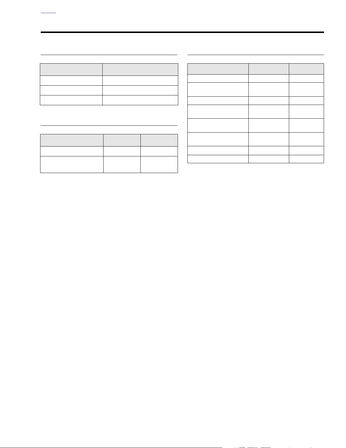
STARTER
Item
Free (no load) speed 3000 rpm (min.) @ 11.5 V
Free (no load) current 90 amp (max.) @ 11.5V
Stall torque 8.0 ft-lbs (10.8 Nm) @ 2.4 V
Specification
SERVICE WEAR LIMITS
Item
Brush length minimum 0.433 11
Commutator diameter
minimum
IN. MM
1.141 29
TORQUE VALUES
Item
Thru-bolts 39-65
End cover mounting
bracket
End cover center screw 90-110
Battery cable terminal
bolts
Starter front and rear
mounting screws
Oil filler spout allen head
socket screws
Starter jackshaft bolt
Solenoid terminal nut 70-90
ft/in-lbs Nm
in-lbs
50-60
in-lbs
in-lbs
60-96
in-lbs
13-20 ft-lbs 18-27 Nm
84-108
in-lbs
60-80
in-lbs
in-lbs
4.4-7.3 Nm
5.6-6.8 Nm
10.2-12.4 Nm
6.8-10.9 Nm
9.5-12.2 Nm
6.8-9.0 Nm
7.9-10.2 Nm
2004 Touring: Starter 5-1
Page 2

HOME
STARTER SYSTEM 5.2
GENERAL
The starter is made up of an armature, field winding assembly, solenoid, drive assembly, idler gear, and drive housing.
The starter motor torque is increased through gear reduction.
The gear reduction consists of the drive pinion on the armature, an idler gear, and a clutch gear in the drive housing. The
idler gear is supported by rollers and the clutch gear is part of
the overrunning clutch/drive assembly.
The overrunning clutch is the part which engages and drives
the clutch ring gear. It also prevents the starter from overrunning. The field windings are connected in series with the
armature through brushes and commutator segments.
The starter relay is a non-repairable part and must be
replaced if it malfunctions.
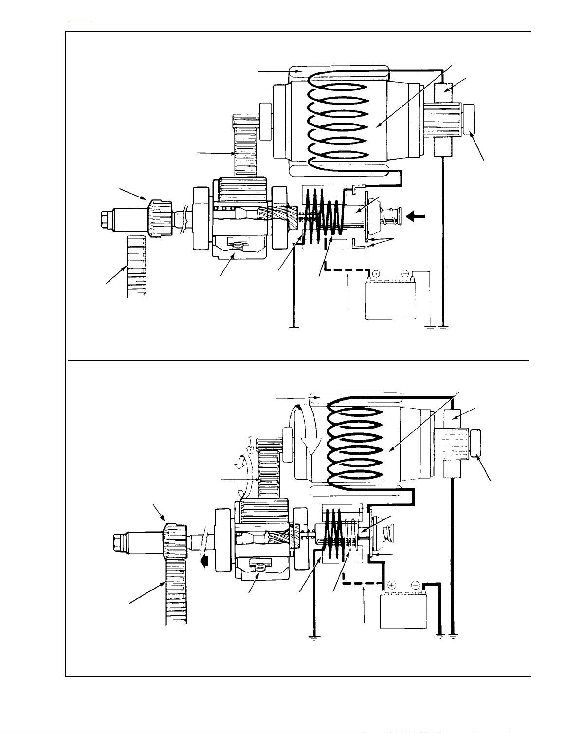
Operation (Figure 5-1)
When the starter switch is pushed, the starter relay is activated and battery current flows into the pull-in winding and
the hold-in winding, to ground.
The magnetic forces of the pull-in and hold-in windings in the
solenoid, pull the plunger and cause it to shift to the left, so
that the pinion gear is engaged with the clutch ring gear. At
the same time, the main solenoid contacts are closed and
battery current flows directly through the field windings to the
armature and to ground. Simultaneously, the pull-in winding
is opened.
The current continues flowing through the hold-in winding,
keeping the main solenoid contacts closed. At this point the
starter begins to crank the engine.
After the engine has started, the pinion gear turns freely on
the pinion shaft through the action of the overrunning clutch
which prevents the armature overrunning by the rotation of
the clutch ring gear.
When the starter switch is released, the current of the hold-in
winding is fed through the main solenoid contacts and the
direction of the current in the pull-in winding is reversed. The
solenoid plunger is returned to its original position by the
return spring, disengaging the pinion gear from the clutch
ring gear.
5-2 2004 Touring: Starter
Page 3
HOME
Pinion
gear
Idler gear
STARTER AT MOMENT STARTER SWITCH IS CLOSED
Field winding
Plunger
Armature
Brush
Ball
bearing
Main
contacts
Clutch
ring gear
Pinion
gear
Overrunning
Idler gear
clutch
Field winding
Hold-In
winding
STARTER DURING CRANKING
Pull-In
winding
Start
circuit. See
wiring
diagram.
Battery
Armature
Brush
Ball
bearing
Plunger
Main
contacts
Clutch
ring gear
Overrunning
clutch
Figure 5-1. Starter Operation
Hold-in
winding
Pull-In
winding
Start circuit.
See wiring
diagram
Battery
2004 Touring: Starter 5-3
Page 4
HOME
STARTER RELAY 5.3
REMOVAL
FLHR/C/S
FLHR/C/S
1. Remove left side saddlebag. See Section 2.25 SAD-
DLEBAG, REMOVAL.
2. Gently pull side cover from frame downtubes (no tools
required).
3. Depress latches on maxi-fuse holder and then slide
cover rearward to disengage tongue from groove in fuse
block cover.
4. Pull fuse block from tabs on mounting panel. Tabs on
panel fit into slots on each side of fuse block cover.
NOTE
The fuse block cover also serves as the spare fuse holder.
One spare 10 amp and 15 amp fuse are provided.
5. Remove the fuse block cover. Raise lipped side slightly
to disengage slots from tabs on fuse block.
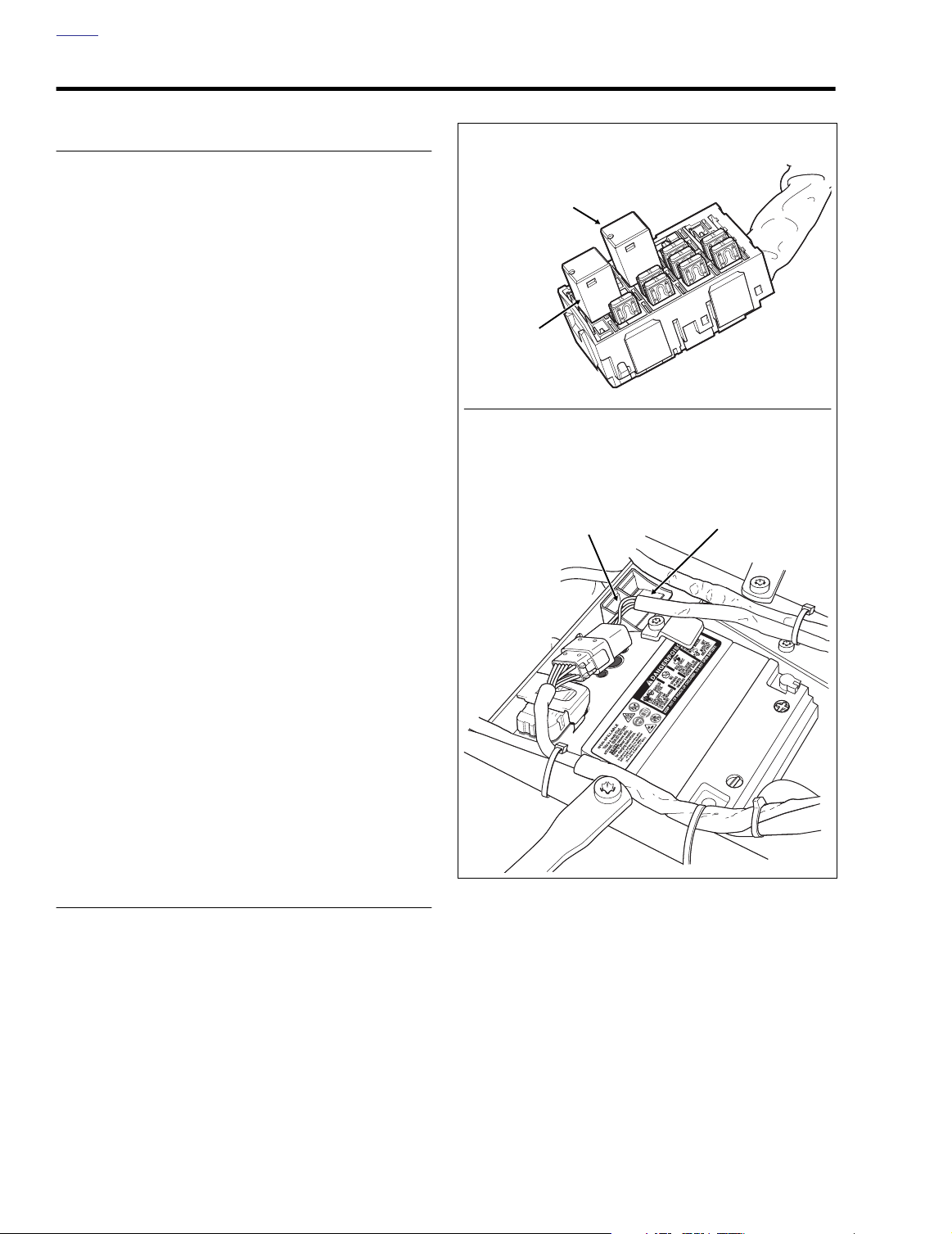
6. Pull relay from slots in fuse block. See upper frame of
Figure 5-2.
Brake Light
Relay [124]
Starter
Relay [123]
Check the wire tags for positive
identification of relays. Starter
relay can be positively identified
by heavy gauge Green wire.
NOTE
Starter
Relay [123]
f2210x8x
FLTR, FLHT/C/U
Ignition Keyswitch
Relay [126]
FLTR, FLHT/C/U
1. Remove seat. See Section 2.24 SEAT, REMOVAL.
2. Locate the starter relay installed in cavity of frame crossmember at rear of battery box. See lower frame of Fig-
ure 5-2.
3. Place a finger on the rubber molding to hold it in position, and using a needle nose pliers, carefully pull on tab
to release starter relay. Since the position of the relays
may be reversed, starter relay can be positively identified by heavy gauge Green wire.
4. Remove harness connector from bottom of relay.
INSTALLATION
FLHR/C/S
1. Install
7. Slide cover over fuse block until slots fully engage tabs
8. Slide fuse block into position on mounting panel. Tabs on
new
relay in fuse block.
on block.
panel fit into slots on each side of fuse block cover.
f2192x8x
Figure 5-2. Locate Starter Relay
9. Slide maxi-fuse cover forward to engage tongue in
groove of fuse block cover and then insert maxi-fuse
holder into cover until latches engage.
10. Align barbed studs in side cover with grommets in frame
downtubes and push firmly into place (no tools
required).
5-4 2004 Touring: Starter
Page 5

HOME
11. Install left side saddlebag. See Section 2.25 SADDLE-
BAG, INSTALLATION.
FLTR, FLHT/C/U
1. Install harness connector at bottom of
2. Place a finger on the molding to hold it in position and
push on relay until seated in cavity of frame crossmember.
3. Install seat. See Section 2.24 SEAT, INSTALLATION.
new
relay.
2004 Touring: Starter 5-5
Page 6

f2268x8x
Frame
Cross Member
Frame Hole
Cruise Cable
Routing Only
Main Power
To Maxi-Fuse
Negative
Battery Cable
Positive
Battery Cable
HOME
STARTER 5.4
REMOVAL
1. Remove seat. See Section 2.24 SEAT, REMOVAL.
1WARNING1WARNING
To protect against shock and accidental start-up of vehicle, disconnect the negative battery cable before proceeding. Inadequate safety precautions could result in
death or serious injury.
2. Unthread bolt and remove battery negative cable (black)
from battery negative (-) terminal.
3. Remove the primary chaincase cover. See Section 6.5
PRIMARY CHAINCASE, REMOVAL, steps 3-8.
4. Bend tab on lockplate away from head of jackshaft bolt.
5. Holding pinion gear to prevent rotation, remove the jackshaft bolt with lockplate and thrust washer.
6. From right side of motorcycle, remove starter front
mounting screw with lockwasher. Remove rear mounting
screw with lockwasher (and battery negative cable ring
terminal). Remove Keps nut from stud of bracket tab and
remove exhaust support bracket.
7. Pull back rubber boot and remove flange nut from starter
post. Remove main power and battery positive cable
ring terminals from starter post. See Figure 5-3.
8. Depress external latch and pull solenoid connector from
top of starter housing.
9. Locate oil filler plug/dipstick on right side of motorcycle
at top of transmission case. To remove the oil filler plug,
pull steadily while moving plug back and forth.
10. Remove the starter from the right side of the motorcycle,
carefully sliding it through the space between the
exhaust pipe and side cover.
NOTE
If necessary, remove allen screw and decorative chrome
cover to facilitate starter removal.
11. Remove the coupling from the starter motor output shaft,
if necessary.
12. Before disassembly, perform tests on the assembled
starter. See DISASSEMBLY, TESTING AND REPAIR in
this section.
INSTALLATION
1. Inspect the retaining ring within the output shaft coupling
for damage or distortion. Replace as necessary. With the
counterbore on the outboard side, install the coupling on
the starter motor output shaft, if removed.
Figure 5-3. Battery Cable Routing (Right Side View)
2. From right side of motorcycle, tilt starter and work into its
installed position. Starter output shaft coupling must
remain on shaft and mate to starter jackshaft. See Section 5.6 STARTER JACKSHAFT, if necessary.
3. Install oil filler plug/dipstick at top of transmission case
on right side of motorcycle.
4. Install slot of exhaust support bracket onto stud of
bracket tab aligning other holes with those in starter
flange. Start Keps nut on stud.
5. Engaging hole in exhaust support bracket, install starter
front mounting screw with lockwasher. Install rear
mounting screw with lockwasher (and battery negative
cable ring terminal) in the same manner.
6. Alternately tighten starter front and rear mounting
screws to 13-20 ft-lbs (18-27 Nm). Tighten Keps nut on
stud of bracket tab.
7. Install battery positive and main power cable ring terminals onto starter post. Install flange nut and tighten to
70-90
in-lbs
(7.9-10.2 Nm). Pull down rubber boot over
terminal connections on starter post. See Figure 5-3.
8. Snap solenoid connector to terminal at top of starter
housing.
NOTE
If removed, install allen screw to fasten decorative chrome
cover to starter.
2004 Touring: Starter 5-6
Page 7

HOME
1. Field wire
2. Thru-bolt (2)
3. Field coil
4. End cap
5. End cap screw (2)
6. Brush spring (4)
7. Brushes
8. Brush holder
9. Armature
10. Armature bearings
11. Drive housing mounting screw (2)
12. Lockwasher (2)
13. Drive housing
14. Solenoid housing
9
14
10
21
22
15. Drive assembly/overrunning clutch
16. Idler gear
17. Idler gear bearing & cage
18. O-ring
19. Spring
20. Shaft
21. Return spring
22. Ball
23. O-ring (2)
23
7
6
3
23
10
16
4
5
2
7
8
1
17
12
11
Figure 5-4. Starter
NOTE
If removed, install allen screw to fasten decorative chrome
cover to starter.
9. Slide lockplate and
bolt, if removed. Insert bolt into jackshaft bore.
10. Insert key on lockplate through slot in thrust washer and
into keyway on jackshaft. Thread the jackshaft bolt into
the starter shaft making sure that the lockplate key
remains in the keyway.
new
thrust washer onto jackshaft
20
19
15
18
13
11. Holding pinion gear to prevent rotation, tighten jackshaft
bolt to 60-80
against flat of bolt head to secure.
12. Install the primary chaincase cover. See Section 6.5
PRIMARY CHAINCASE, INSTALLATION, steps 20-31.
13. Insert bolt through battery negative cable (black) into
threaded hole of battery negative (-) terminal. Tighten
bolt to 60-96
14. Install seat. See Section 2.24 SEAT, INSTALLATION.
in-lbs
(6.8-9.0 Nm). Bend tab on lockplate
in-lbs
(6.8-10.9 Nm).
f1107axx
2004 Touring: Starter 5-7
Page 8

HOME
DISASSEMBLY, TESTING AND REPAIR
1. See Figures 5-4 and 5-5. Disconnect field wire (1).
3497
Figure 5-5. Remove Thru-Bolts
2. See Figures 5-4 and 5-6. Remove thru-bolts (2).
Remove field coil (3) and end cap (4).
3. See Figures 5-7 and 5-8. Remove the end cap screws
and cap.
3500
Figure 5-7. Remove End Cap Screws and O-Rings
3501
3498
3499
Figure 5-8. Remove End Cap
4. See Figures 5-4 and 5-9. Disengage brush springs (6)
and pull field coil brushes (7) out of brush holders (8).
3502
Figure 5-6. Remove Field Coil and Cap
5-8 2004 Touring: Starter
Figure 5-9. Remove Brush Holder
Page 9

HOME
CAUTION
2231
Commutator
Starting groove in mica
with 3 cornered file
Mica
Segments
Wrong way
Mica must not be left
with a thin edge next to
segments.
Figure 5-10. Undercutting the Mica Separators
5. Check the brush length. Brushes less than 0.433 inch
(11 mm) long should be replaced.
NOTE
Replace brushes in sets of four only.
●
Field coil and brush holder brushes are attached to field
●
coil and brush holder. To replace brushes, replace field
coil and brush holder.
6. See Figure 5-4. Remove armature (9).
7. Place armature in lathe or truing stand and check runout
of commutator. Commutators with more than 0.015 in.
(0.38 mm) of runout should be replaced or machined on
a lathe. Commutators should be replaced when diameter is less than 1.141 in. (29.98 mm).
Commutator
Undercutting mica with piece
of hacksaw blade
Mica
Right way
Mica must be cut away
clean between segments.
Do not use sandpaper or emery cloth on commutator.
The abrasive grit may remain on commutator segments
and could cause excessive brush wear.
10. See Figure 5-11. Check for SHORTED ARMATURE with
a growler. Place armature on growler. Hold a thin steel
strip (hacksaw blade) against armature core and slowly
turn armature. A shorted armature will cause the steel
strip to vibrate and be attracted to the core. Shorted
armatures should be replaced.
8. Check depth of mica on commutator. If undercut is less
than 0.008 in. (0.20 mm), use an undercutting machine
to undercut the mica to 1/32 in. (0.79 mm) deep. The
slots should then be cleaned to remove any dirt or copper dust.
9. See Figure 5-10. If an undercutting machine is not available, undercutting can be done satisfactorily using a thin
hacksaw blade. After undercutting, lightly sand the
armature with crocus cloth to remove any burrs.
Figure 5-11. Shorted Armature Test Using Growler
2004 Touring: Starter 5-9
Page 10

HOME
11. See Figure 5-12. Check for a GROUNDED ARMATURE
with an ohmmeter or continuity tester. Touch one probe
to any commutator segment, and the other probe to the
armature core. There should be no continuity (infinite
ohms). If there is any continuity the armature is
grounded and should be replaced.
Figure 5-12. Grounded Armature Test
13. See Figure 5-14. Check for GROUNDED FIELD WINDING with an ohmmeter or continuity tester. Touch one
probe to the frame, and the other probe to each of the
brushes attached to the field winding. There should be
no continuity (infinite ohms). If there is any continuity at
either brush, the field winding(s) are grounded and the
field frame should be replaced.
Figure 5-14. Grounded Field Test
12. See Figure 5-13. Check for OPEN ARMATURE with an
ohmmeter or continuity tester. Check for continuity
between all commutator segments. There should be
continuity (0 ohms) at all test points. No continuity at any
test point indicates armature is open and should be
replaced.
Figure 5-13. Armature Open Test
14. See Figure 5-15. Check for OPEN FIELD WINDING with
an ohmmeter or continuity tester. Touch one probe to the
field wire, and the other probe to each of the brushes
attached to the field coils. There should be continuity. If
there is no continuity at either brush, the field winding(s)
are open and the field frame should be replaced.
Figure 5-15. Open Field Test
5-10 2004 Touring: Starter
Page 11

HOME
f1540a5x
3506
15. See Figure 5-16. Te st BRUSH HOLDER INSULATION
with an ohmmeter or continuity tester. Touch one probe
to holder plate and the other probe to each of the positive (insulated) brush holders. There should be no continuity (infinite ohms). If there is continuity at either brush
holder, the brush holder assembly should be replaced.
To uch one probe to the non-insulated brush holders and
the other probe to the holder plate. If you measure any
resistance, the brush holder must be replaced.
f1541x5x
Figure 5-16. Brush Holder Insulation Test
16. Check armature bearings (10) and replace if necessary.
See Figure 5-4.
NOTE
Spring (21) and ball (22) are loose in shaft gear end. See
Figure 5-4.
Figure 5-18. Drive Housing Assembly
Figure 5-19. Clutch Assembly
17. See Figures 5-4, 5-17 and 5-18. Remove the two drive
housing mounting screws (11) and washers (12).
Remove drive housing (13) from solenoid housing (14).
18. See Figures 5-4 and 5-19. Remove drive (15), idler gear
(16) and idler gear bearing (17) from drive housing (13).
O-ring (18) is in groove in drive housing.
f1557x5x
19. Remove spring (19) and shaft (20).
Figure 5-17. Remove Drive Housing
2004 Touring: Starter 5-11
Page 12

HOME
ASSEMBLY
1. See Figure 5-4. Replace O-rings (18, 23).
CAUTION
Do not use solvents to clean drive assembly/over-running clutch (15). It is lubricated and sealed. If you use a
solvent to clean it, the lubricant will be washed out and
the clutch will fail.
2. Clean, inspect and lubricate drive assembly components. Lubricate parts with high temperature grease
such as LUBRIPLATE 110.
3. When installing drive assembly components, open end
of idler bearing cage (17) faces toward solenoid.
4. When installing drive housing (13) to solenoid housing
(14) use new O-ring (18). Be sure to install return spring
(21) and ball (22).
5. Lubricate armature bearings (10) with high temperature
grease such as LUBRIPLATE 110. Install armature (9)
and field coil (3) to solenoid housing (14).
6. Replace brush springs (6), if necessary. Install brushes
(7) and brush holder (8).
7. Install end cap (4) with screws (5).
8. Install thru-bolts (2).
9. Connect field wire (1) to solenoid terminal. Tighten solenoid terminal nut to 70-90
in-lbs
(7.9-10.2 Nm).
5-12 2004 Touring: Starter
Page 13

HOME
STARTER SOLENOID 5.5
GENERAL
The starter solenoid is a switch designed to open and close
the starting circuit electromagnetically. The switch consists of
contacts and a winding around a hollow cylinder containing a
movable plunger. When the winding is energized by the battery, the magnetism produced pulls the plunger into the coil.
The plunger moves against two main switch contacts, closing
the circuit.
DISASSEMBLY
1. See Figure 5-20. Remove screws and washers. Clip
comes off with screw.
Solenoid
Housing
Plunger
2. Remove cover and gasket. Discard gasket.
3. Plunger can now be removed from solenoid housing.
ASSEMBLY
1. Replace wire connection hardware as necessary.
2. Apply a light coat of Lubriplate® 110 to plunger shaft.
Install plunger in solenoid housing.
3. Install
Gasket
new
gasket. Place cover in position and install
screws, washers and clip.
Cover
Clip
Screw and
Washer
5-13 2004 Touring: Starter
CAUTION
Do not tighten the inside nut without
removing other items shown. Movement
will cause damage to the contact.
Figure 5-20. Starter Solenoid
f1079axx
Page 14

HOME
7945
Starter
Jackshaft
Assembly
STARTER JACKSHAFT 5.6
REMOVAL/DISASSEMBLY
1. Remove seat. See Section 2.24 SEAT, REMOVAL.
1WARNING1WARNING
To protect against shock and accidental start-up of vehicle, disconnect the negative battery cable before proceeding. Inadequate safety precautions could result in
death or serious injury.
2. Unthread bolt and remove battery negative cable (black)
from battery negative (-) terminal.
3. See Figure 5-21. Remove the primary chaincase cover.
Remove the clutch assembly, primary chain and compensating sprocket components as a single assembly.
See Section 6.5 PRIMARY CHAINCASE, REMOVAL,
steps 3-15.
NOTE
If only the jackshaft bolt, thrust washer, lockplate, pinion gear
and/or spring require servicing, then the primary chain and
clutch assembly may be left in place.
Figure 5-21. Primary Chaincase
f1211c5x
Jackshaft
Bolt
Key
Lockplate
Coupling
Spring
Slot
Retaining
Ring
Pinion
Gear
Thrust
Tab
Washer
Figure 5-22. Starter Jackshaft Assembly
Retaining
Keyway
Jackshaft
Primary
Cover Bushing
Ring
Output
Shaft
Coupling
Counterbore
Primary Chaincase
Bushing
2004 Touring: Starter 5-14
Page 15

HOME
4. Bend tab on lockplate away from head of jackshaft bolt.
See Figure 5-22.
5. Holding pinion gear to prevent rotation, remove the jack-
shaft bolt with lockplate and thrust washer.
6. Carefully pull jackshaft assembly from the primary chain-
case bore.
7. Remove the pinion gear from the jackshaft.
8. Remove the coupling from the jackshaft. Remove the
spring from the coupling.
CAUTION
Do not force the output shaft coupling through the oil
seal in the primary chaincase or the resulting damage
will require seal replacement.
9. From right side of motorcycle, remove starter front
mounting screw with lockwasher. Remove rear mounting
screw with lockwasher (and battery negative cable ring
terminal). Remove Keps nut from stud of bracket tab and
remove exhaust support bracket.
10. Pull back rubber boot and remove flange nut from starter
post. Remove main power and battery positive cable
ring terminals from starter post.
11. Depress external latch and pull solenoid connector from
top of starter housing.
12. Locate oil filler plug/dipstick at top of transmission case.
To remove the oil filler plug, pull steadily while moving
plug back and forth.
13. Remove the starter from the right side of the motorcycle,
carefully sliding it through the space between the
exhaust pipe and side cover.
NOTE
If necessary, remove allen screw and decorative chrome
cover to facilitate starter removal.
14. Remove the coupling from the starter motor output shaft.
ASSEMBLY/INSTALLATION
NOTE
To replace the jackshaft bushings and/or seals in the primary
chaincase or primary chaincase cover, see Section 6.5 PRI-
MARY CHAINCASE, DISASSEMBLY.
1. Inspect the retaining ring within the output shaft coupling
for damage or distortion. Replace as necessary. With the
counterbore on the outboard side, install the coupling on
the starter motor output shaft, if removed.
2. From right side of motorcycle, tilt starter and work into its
installed position. Starter output shaft coupling must
remain on shaft and mate to starter jackshaft.
3. Install oil filler plug/dipstick at top of transmission case.
4. Install slot of exhaust support bracket onto stud of
bracket tab aligning other holes with those in starter
flange. Start Keps nut on stud.
5. Engaging hole in exhaust support bracket, install starter
front mounting screw with lockwasher. Install rear
mounting screw with lockwasher (and battery negative
cable ring terminal) in the same manner.
6. Alternately tighten starter front and rear mounting
screws to 13-20 ft-lbs (18-27 Nm). Tighten Keps nut on
stud of bracket tab.
7. Install battery positive and main power cable ring terminals onto starter post. Install flange nut and tighten to
70-90
in-lbs
(7.9-10.2 Nm). Pull down rubber boot over
terminal connections on starter post.
8. Snap solenoid connector to terminal at top of starter
housing.
NOTE
If removed, install allen screw to fasten decorative chrome
cover to starter.
9. Inspect the retaining ring within the coupling for damage
or distortion. Replace as necessary.
10. Insert narrow end of jackshaft into shallow side of coupling until gear face contacts installed retaining ring.
(Look at position of retaining ring within coupling to
determine shallow side.)
11. Slide spring over narrow end of jackshaft until it contacts
retaining ring.
12. Slide pinion gear over narrow end of jackshaft until it
contacts spring.
13. Slide lockplate and
bolt, if removed. Insert bolt into jackshaft bore.
14. Gently insert jackshaft assembly into primary chaincase
so that splined end of shaft engages coupling on starter
output shaft.
15. Insert key on lockplate through slot in thrust washer and
into keyway on jackshaft. Thread the jackshaft bolt into
the starter shaft making sure that the lockplate key
remains in the keyway.
16. Holding pinion gear to prevent rotation, tighten jackshaft
bolt to 60-80
against flat of bolt head to secure.
17. Install the clutch, primary chain, and compensating
sprocket components. Install the primary chaincase
cover. See Section 6.5 PRIMARY CHAINCASE,
INSTALLATION, steps 9-31.
18. Insert bolt through battery negative cable (black) into
threaded hole of battery negative (-) terminal. Tighten
bolt to 60-96
19. Install seat. See Section 2.24 SEAT, INSTALLATION.
new
thrust washer onto jackshaft
in-lbs
(6.8-9.0 Nm). Bend tab on lockplate
in-lbs
(6.8-10.9 Nm).
2004 Touring: Starter 5-15
Page 16

HOME
NOTES
5-16 2004 Touring: Starter
 Loading...