

Page 1
4
HOME
BULB CHART 8.1
GENERAL
The chart below gives the bulb requirements for FLHTP and
FLHP police model motorcycles.
For Cycle Signal Lamp replacement bulbs, phone Whelen
Engineering at (203) 526-9504.
NOTE
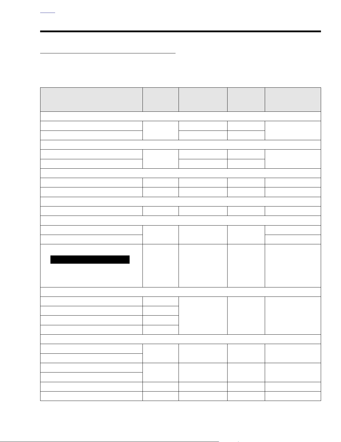
Table 8-1. Bulb Chart FLHTP/FLHP
LAMP DESCRIPTION
(ALL LAMPS 12V)
Head Lamp
Low Beam
HIgh Beam 5.00 60
Tail/Stop Lamp
Ta il Lamp
Stop Lamp 2.10 24
Turn Signal Lamp
Front / Running 2 2.25 / 0.59 27/7 68168-89
Rear 2 2.25 27 68572-64B
Rear Fender Tip Lamp
Rear Fender Tip Bulb 2 0.33 3.7 53439-79
Pursuit Lamp
Left (Red)
Right (Blue) 68728-64
Rear Strobe, if provided
NUMBER OF
BULBS
(REQUIRED)
1
1
12.530
CURRENT DRAW
(AMPERAGE)
4.58 55
0.59 6
WATTAGE
HARLEY-DAVIDSON
PA RT NUMBER
68329-03
68167-88
68727-64A
1
WARNING
As a high voltage source, rear strobe must
be off at least 10 minutes before servicing.
Inadequate safety precautions may result
in death or serious injury. (00097a)
Instrument Panel Lamps-FLHTP
High Beam Indicator 1
Oil Pressure Indicator 1
Neutral Indicator 1
Tu rn Signal Indicator 2
Gauge Lamps-FLHTP
Speedometer
Ta c hometer
Voltmeter
Fuel Gauge
Engine** N/A N/A N/A N/A
Pursuit 1 0.08 1.1 68642-96
**
LED illuminated. LED’s are
**
**
not
repairable. Assembly must be replaced if LED fails.
N/A N/A N/A N/A
1 0.24 3.4 67445-00
N/A 20 67598-88
0.15 2.1 68024-94
2004 FLT Police: Electrical 8-1
Page 2
HOME
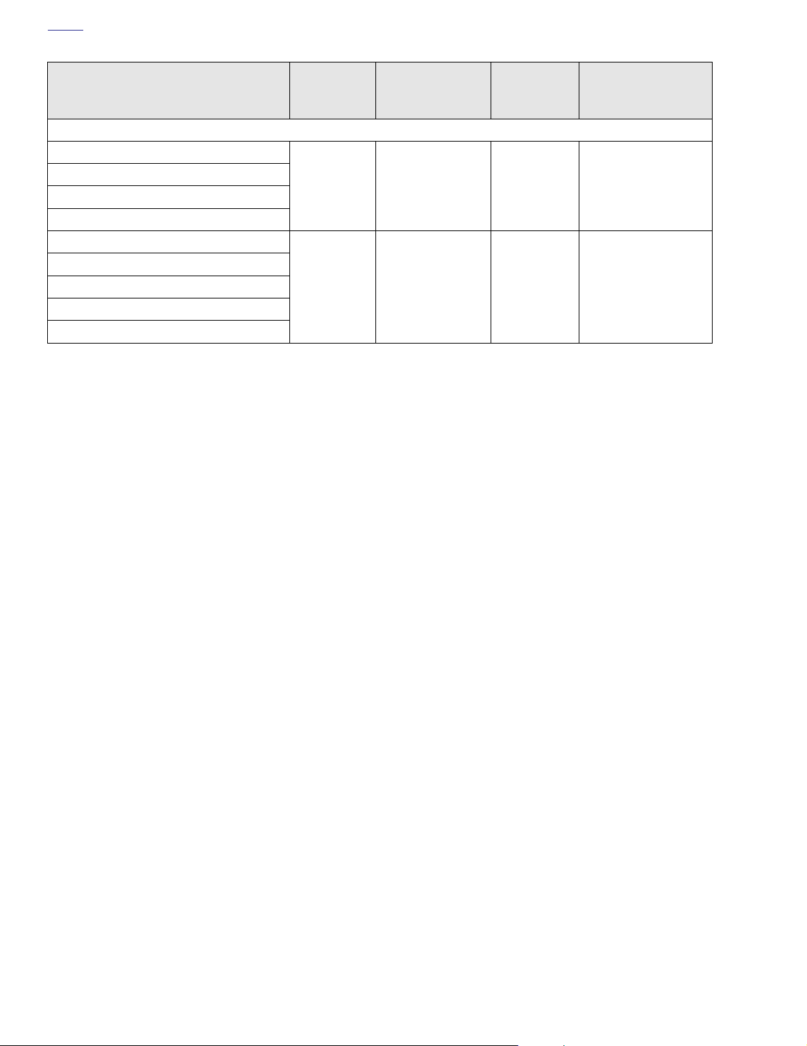
Table 8-1. Bulb Chart FLHTP/FLHP
LAMP DESCRIPTION
(ALL LAMPS 12V)
Instrument/Gauge Lamps-FLHP Indicator Module (with LED’s)
High Beam Indicator
Oil Pressure Indicator
Neutral Indicator
Tu rn Signal Indicator
Fuel Gauge
Speedometer**
Odometer**
Engine**
Pursuit**
**
LED illuminated. LED’s are
**
not
repairable. Assembly must be replaced if LED fails.
NUMBER OF
BULBS
(REQUIRED)
N/A 0.05 N/A 68113-99
N/A N/A N/A N/A
CURRENT DRAW
(AMPERAGE)
WATTAGE
HARLEY-DAVIDSON
PA RT NUMBER
8-2 2004 FLT Police: Electrical
Page 3
HOME
CAUTION
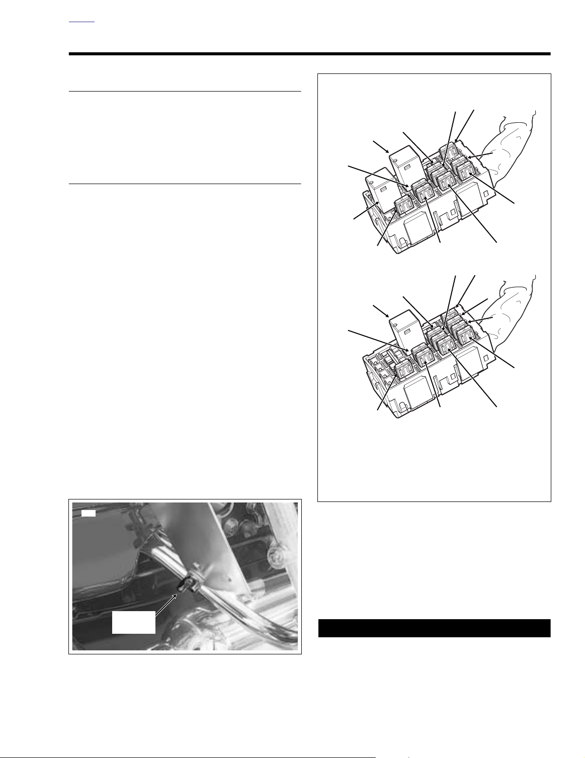
System Fuse Block (Under Left Side Cover)
11
10
9
1
8
5
4
3
2
FLHP/E
11
10
9
1
8
7
6
5
4
3
2
FLHTP
1. Headlamp
2. Ignition
3. Lighting
4. Instruments
5. Brakes/Pursuit
6. Radio Memory
7. Siren
8. Accessory
9. Battery
10. Brake Light Relay
11. P&A
12. Starter Relay
12
f2283x8x
f2204x8x
7
SYSTEM FUSES/RELAYS 8.2
GENERAL
Fuses are provided to protect electrical components. To
inspect or replace the fuses, carefully follow the procedures
below. If an electrical fault occurs after replacement of a fuse,
see your Harley-Davidson dealer for service.
SYSTEM FUSES
Removal
1. Verify that the Ignition/Light Key Switch is turned to the
OFF position.
2. Remove left side saddlebag.
3. Remove wing nut style bolt to release bottom of siren
amplifier mounting bracket from clamp on saddlebag
guard. Rotate bracket upward to gain complete access to
side cover area. Loosen top bolt, if necessary. See Fig-
ure 8-1.
4. Gently pull side cover from frame downtubes (no tools
required). Exercise caution to avoid scratching side cover
on amplifier mounting bracket.
5. Depress latches on maxi-fuse holder and then slide
cover rearward to disengage tongue from groove in fuse
block cover.
6. Pull fuse block from tabs on mounting bracket. Tabs on
bracket fit into slots on each side of fuse block cover.
The fuse block cover also serves as the spare fuse holder.
One spare 10 amp and 15 amp fuse are provided.
NOTE
7. Remove the fuse block cover. Raise lipped side slightly
to disengage slots from tabs on fuse block.
8243
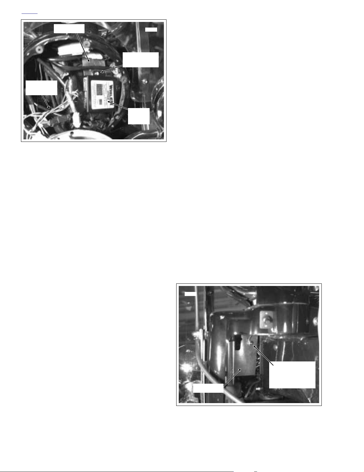
Wing Nut
Style Bolt
Figure 8-1. Siren Amplifier Mounting Bracket
Figure 8-2. Fuse Locations
8. Remove fuse from fuse block and inspect the element.
See Figure 8-2. Replace fuse if element is burned or broken. Automotive type ATO fuses are used.
NOTE
The fuse block cover also serves as the spare fuse holder.
One spare 10 amp and 15 amp fuse are provided.
Always use replacement fuses that are of the correct
type and value. Use of incorrect fuses can result in damage to the electrical system. See Tab le 8-2. (00222a)
2004 FLT Police: Electrical 8-3
Page 4

HOME
Table 8-2. FLHTP/FLHP System Fuses
CIRCUIT
Maxi-Fuse 40 Orange
Headlamp 15 Blue
Ignition 15 Blue
Lighting 15 Blue
Instruments 15 Blue
Brakes/Pursuit 15 Blue
Radio Memory 15 Blue
Siren 10 Red
Accessory 15 Blue
Battery 15 Blue
P & A 15 Blue
RATING
(AMPERES)
COLOR
Installation
1. Install fuse in fuse block.
2. Slide cover over fuse block until slots fully engage tabs
on block.
3. Slide fuse block into position on mounting bracket. Tabs
on bracket fit into slots on each side of fuse block cover.
4. Slide maxi-fuse cover forward to engage tongue in
groove of fuse block cover and then insert maxi-fuse
holder into cover until latches engage.
5. Align barbed studs in side cover with grommets in frame
downtubes and push firmly into place (no tools required).
6. Rotate siren amplifier mounting bracket downward.
Install wing nut style bolt to secure bracket to clamp on
saddlebag guard. Tighten top bolt, if loosened.
7. Install left side saddlebag.
8-4 2004 FLT Police: Electrical
Page 5
HOME
i04382
Chrome
Ring
Phillips
Screw
i04383
Torx
Screws
Torx
Screws
STROBE HEADLAMP 8.3
GENERAL
This Strobe Headlamp Kit is designed for installation on both
FLHP and FLHTP model motorcycles.
NOTE
The Strobe Headlamp Kit as well as replacement Strobe
Lamps (Part Number 68692-02) are available at your HarleyDavidson Dealer.
INSTALLATION
1WARNING1WARNING
To protect against shock and accidental start-up of vehicle, disconnect the negative battery cable before proceeding. Inadequate safety precautions could result in
death or serious injury. (00048a)
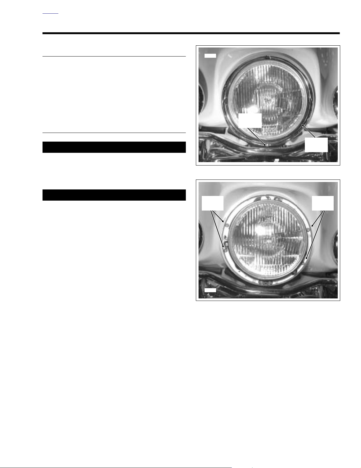
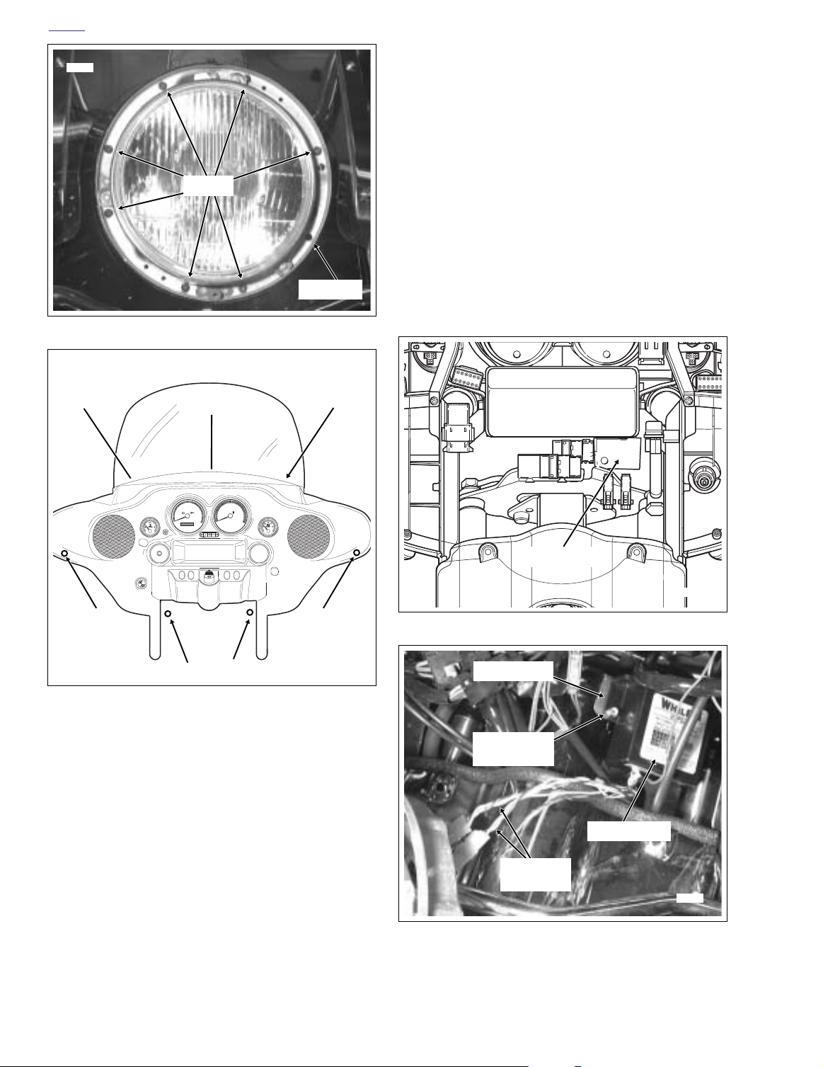
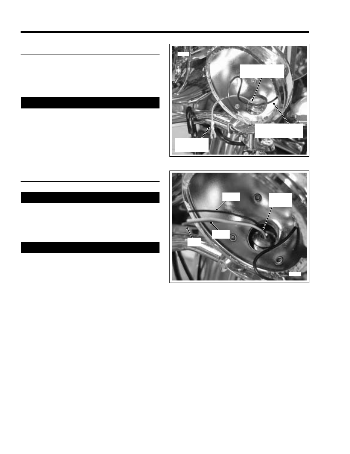
Figure 8-3. Remove Headlamp Door (FLHTP)
1WARNING1WARNING
Always disconnect the negative battery cable first. If the
positive cable should contact ground with the negative
cable installed, the resulting sparks may cause a battery
explosion which could result in death or serious injury.
(00049a)
1. Disconnect battery cables, negative cable first.
2. See Figure 8-3. Remove the Phillips screw at the bottom
of the headlamp door (chrome ring). Remove the headlamp door.
3.
FLHTP:
Remove the four Torx screws to free the head-
lamp housing from the fairing. See Figure 8-4.
FLHP:
Remove the seven Phillips screws to free the
headlamp housing from the headlamp nacelle. See Fig-
ure 8-5.
4. Squeeze the two external tabs (if present) to remove the
wire connector at the back of the headlamp bulb.
Remove the headlamp housing assembly from the vehicle.
5.
FLHP:
Move to step 16.
FLHTP:
Proceed as follows:
a. See Figure 8-6. Standing at the front of the vehicle,
use a T27 TORX drive head to remove the three
outer fairing screws (1, 2 and 3) and flat washers
just below the windshield.
b. Moving to the inner fairing side, use a T27 TORX
drive head to remove the two fairing screws (4 and
7) just above the wind deflectors on the left and right
side.
Figure 8-4. Headlamp Housing Mount (FLHTP)
c. Turn the handlebar to the right and remove the outer
fairing screw (5) reaching in below the left side of the
fairing cap. Turn the handlebar to the left and
remove the fairing screw (6) below the right side of
the fairing cap.
d. Remove the windshield and lift the fairing off the
motorcycle.
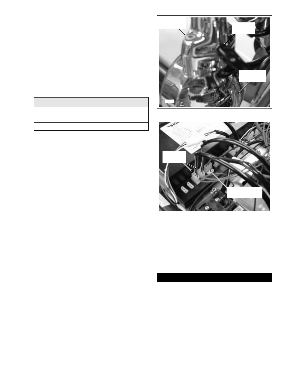
6. Install the power supply as follows:
a. See Figure 8-7. Locate the metal plate on which the
power supply will be mounted. Remove the black
plastic wire retainer (Christmas Tree) from the hole
in the metal plate.
2004 FLT Police: Electrical 8-5
Page 6
HOME
i04384
Screws
Figure 8-5. Headlamp Housing Mount (FLHP)
Not Used
c. Moving to the inner fairing side, reach in under the
fairing cap and slide the screw through the holes in
the metal plate and power supply. Returning to the
front, loosely install lockwasher and locknut.
d. Carefully pull out the two strobe harnesses, the red
(power) wire and the black (ground) wire, so that it is
free of the power supply and other wiring.
7. Obtain ring terminal from kit. Strip 3/8 inch (9.5 mm)
insulation from end of black (ground) wire exiting power
supply. Using a wire crimpers, install and crimp ring terminal to wire.
8. See Figure 8-9. While holding the power supply and
mounting screw in position, remove the locknut and lockwasher loosely installed. Install black (ground) wire ring
terminal onto screw and reinstall lockwasher and locknut.
Tighten locknut securely.
1
2
40
60
50
70
30
50
80
40
90
30
20
100
10
MPH
0
120
C
E
D
R
E
I
T
F
I
H
N
A
R
O
S
L
D
E
I
Y
V
-
D
A
60
20
70
10
110
x100
RPM
0
80
H
N
A
R
O
S
L
D
E
I
Y
V
-
D
A
UNLOCK
4
6
5
3
7
f1755d8x
Figure 8-6. Remove Outer Fairing (FLHTP)
NOTE
When installing the power supply, note that it is not an exact
fit. It may be necessary to manipulate the power supply into
various positions to obtain the optimal alignment and position. Also note that the hole in the metal plate is slightly larger
than the hole in the power supply mount. While the overall fit
may appear less than perfect, the power supply will be secure
once the hardware is fully tightened.
b. See Figure 8-8. Obtain the power supply (with wir-
ing), screw, lockwasher and locknut from kit. Position the power supply, so that the mounting hole on
the left side is aligned with the hole in the metal
plate.
Storage Box
Metal Plate
i04390
Figure 8-7. Locate Metal Mounting Plate (FLHTP)
Metal Plate
Locknut and
Lockwasher
Power Supply
Strobe
Harnesses
i04391
Figure 8-8. Mount Strobe Power Supply (FLHTP)
8-6 2004 FLT Police: Electrical
Page 7
HOME
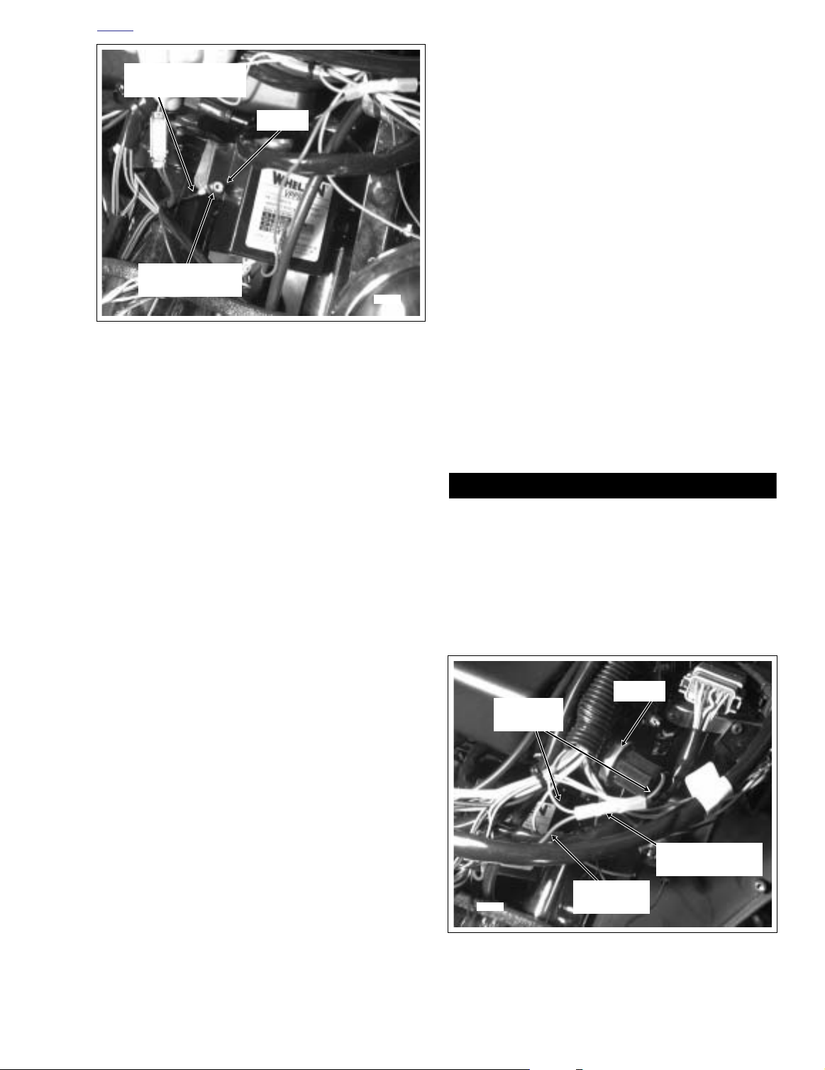
1WARNING1WARNING
i04393
Flasher
Red (Power)
Wire
Sealed Butt
Splice Connector
Gray/Black
Wire
Ground Wire
From Power Supply
Locknut
d. Moving to the inner fairing side, use a T27 TORX
drive head to start the two fairing screws (4 and 7)
just above the wind deflectors on both the left and
right side.
e. Turn the handlebar to the left and reaching in below
the fairing cap, start the right side fairing screw (6).
Tu rn the handlebar to the right and start the fairing
screw (5) on the left side.
f. Alternately tighten the four fairing screws on the
inner fairing side to 20-30
in-lbs
(2.7-3.4 Nm).
g. Moving to the front of the vehicle, tighten the outer
fairing screws below the windshield to 25-30
in-lbs
(2.8-3.4 Nm).
Ring Terminal
and Lockwasher
i04392
Figure 8-9. Install Ground Wire Ring Terminal
9. Route the red (power) wire upward toward the right side
of the plastic storage box and proceed as follows:
NOTE
The flasher is cable strapped to the fairing on the right side of
the storage box.
a. Locate the flasher and remove the three-place con-
nector. Cut the gray/black wire at a point about 4-5
inches (101.6-127.0 mm) from the connector.
b. Strip 3/8 inch (9.5 mm) of insulation from both ends
of gray/black wire. Strip 3/8 inch (9.5 mm) of insulation from red (power) wire from power supply.
c. Obtain the sealed butt splice connector from the kit.
Butt splice the red (power) wire to the gray/black
wire. See Section B.5 SEALED BUTT SPLICE
CONNECTORS in the 2004 Touring Models Service
Manual (Part No. 99483-04). See Figure 8-10.
11. Obtain the new strobe headlamp assembly from the kit.
Reaching in through the headlamp opening of the fairing,
retrieve the two headlamp strobe harnesses. Mate the
harnesses to the connectors at the back of the headlamp.
12. See Figure 8-4. Align holes in new headlamp assembly
with those in fairing (headlamp door bracket at bottom).
Install the four TORX screws.
13. See Figure 8-3. Fit the square-shaped portion of the
headlamp door spring into the slot at the top of the headlamp housing and then snap the headlamp door (chrome
ring) into place. Install the Phillips screw at the bottom of
the headlamp door.
Always connect the positive battery cable first. If the positive cable should contact ground with the negative cable
installed, the resulting sparks may cause a battery explosion which could result in death or serious injury.
(00068a)
14. Install battery cables, positive cable first.
15. Test strobe headlamp for proper operation.
d. Connect the three-place connector to the flasher
and carefully tuck the wiring in and around the existing wiring.
e. Obtain cable strap from kit and fix location of wiring.
Be sure wiring is positioned so that it will not be
pinched or kinked when outer fairing is installed.
10. Install outer fairing as follows:
a. Place the outer fairing on the motorcycle.
b. Place the windshield in position on the inner fairing
aligning the slots with the threaded inserts.
c. See Figure 8-6. Using a T27 TORX drive head, start
the three outer fairing screws (1, 2 and 3) and flat
washers just below the windshield.
Figure 8-10. Flasher and Flasher Connector
2004 FLT Police: Electrical 8-7
Page 8
HOME
Strobe
Harnesses
Metal Plate
i04394
Locknut and
Lockwasher
f. See Figure 8-12. While holding the power supply,
remove the locknut. Remove screw and lockwasher
allowing power supply to seat inside the nacelle.
Route black (ground) wire to the rear of the metal
plate. Install ring terminal and lockwasher on screw.
Slide the screw through the metal plate and power
supply and install locknut. Tighten locknut securely.
g. Locate the white two-place connector inside the
headlamp nacelle (pursuit switch) and carefully pull
both connector and wiring free. Cut the gray/purple
wire at a point about 2-3 inches from the connector.
Power
Supply
Figure 8-11. Mount Strobe Power Supply (FLHP)
16.
FLHP:
Install the power supply as follows:
NOTE
When installing the power supply, note that it is not an exact
fit. It may be necessary to manipulate the power supply into
various positions to obtain the optimal alignment and position. Also note that the hole in the metal plate is slightly larger
than the hole in the power supply mount. While the overall fit
may appear less than perfect, the power supply will be secure
once the hardware is fully tightened.
a. See Figure 8-11. Locate the metal plate on which
the power supply will be mounted. Remove the black
plastic wire retainer (Christmas Tree) from the hole
in the plate.
b. Obtain the power supply (with wiring), screw, lock-
washer and locknut from kit. Install lockwasher on
screw. Position the power supply, so that the upper
mounting hole is aligned with the hole in the metal
plate.
h. Strip 3/8 inch of insulation from both ends of gray/
purple wire. Strip 3/8 inch of insulation from red
(power) wire from power supply.
i. Obtain the sealed butt splice connector from the kit.
Butt splice the red (power) wire to the gray/purple
wire. See Section B.5 SEALED BUTT SPLICE
CONNECTORS in the 2004 Touring Models Service
Manual (Part No. 99483-04).
j. Carefully tuck the wiring in and around the existing
wiring. Obtain cable strap from kit and fix location of
wiring. Be sure wiring is positioned so that it will not
be pinched or kinked when headlamp housing is
installed.
17. See Figure 8-13. Obtain the new strobe headlamp
assembly from the kit. Reaching into the headlamp
nacelle, retrieve the two headlamp strobe harnesses.
Mate the harnesses to the connectors at the back of the
headlamp.
18. Align holes in headlamp housing with those in headlamp
nacelle (headlamp door bracket at bottom). Install the
seven Phillips screws.
i04395
c. Moving to the rear of the handlebars, reach in under
the headlamp nacelle and slide the screw through
the holes in the metal plate and power supply.
Returning to the front of the motorcycle, loosely
install locknut.
d. Carefully pull out the two strobe harnesses, the red
(power) wire and the black (ground) wire, so that it is
free of the power supply and other wiring.
e. Obtain ring terminal from kit. Strip 3/8 inch insulation
from end of black (ground) wire exiting power supply.
Using a wire crimpers, install and crimp ring terminal
to end of wire.
8-8 2004 FLT Police: Electrical
Ground Wire
Ring Terminal
Metal Plate
and Lockwasher
Figure 8-12. Install Ground Wire Ring Terminal
Screw with
Page 9
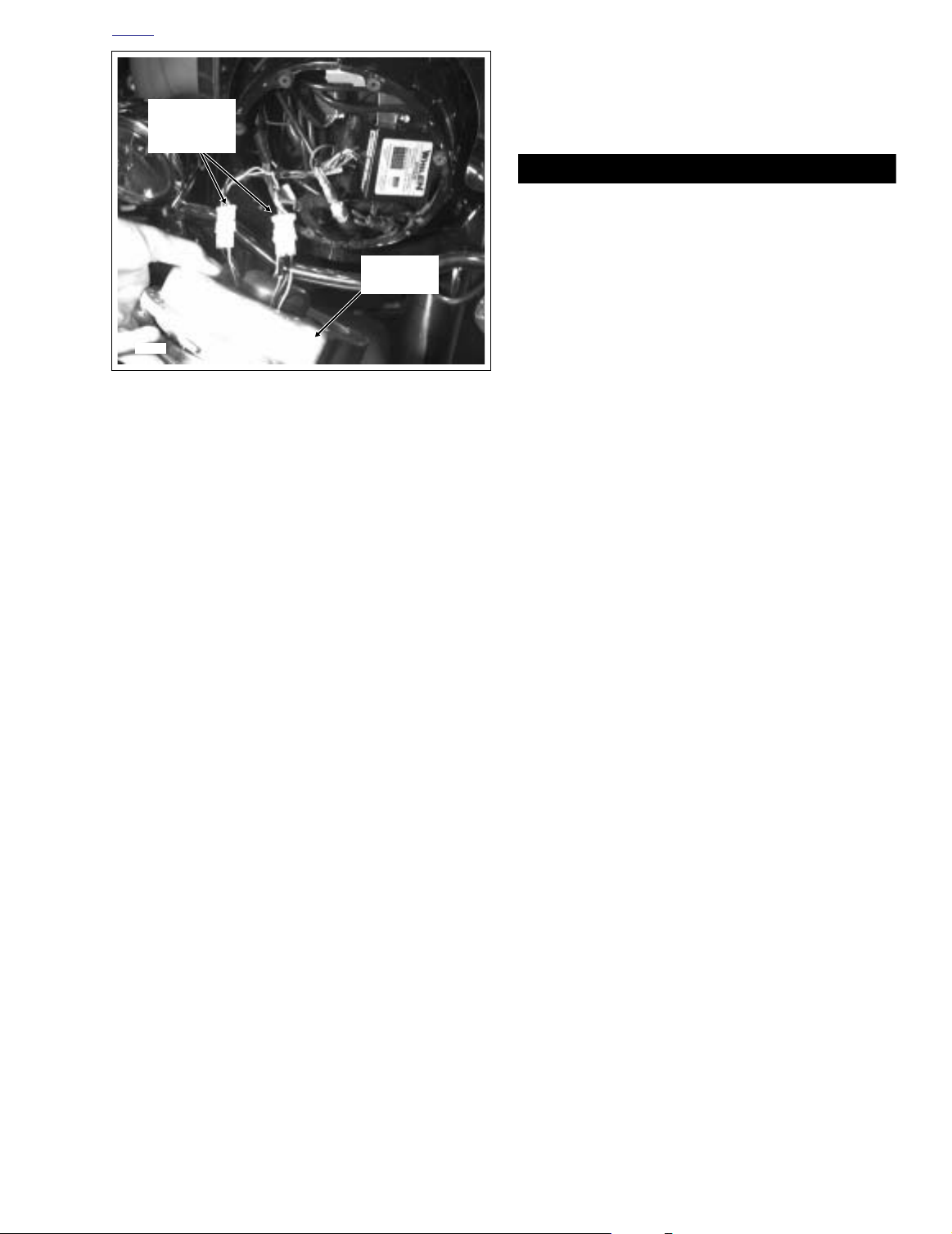
HOME
1WARNING1WARNING
Strobe
Harness
Connectors
Headlamp
Assembly
i04396
Figure 8-13. Install Strobe Harness to Headlamp
19. Fit the square-shaped portion of the headlamp door
spring into the slot at the top of the headlamp housing
and then snap the headlamp door (chrome ring) into
place. Install the Phillips screw at the bottom of the headlamp door. See Figure 8-3.
Always connect the positive battery cable first. If the positive cable should contact ground with the negative cable
installed, the resulting sparks may cause a battery explosion which could result in death or serious injury.
(00068a)
20. Install battery cables, positive cable first.
21. Test strobe headlamp for proper operation.
2004 FLT Police: Electrical 8-9
Page 10
HOME
STROBE KIT (PAR-36) 8.4
GENERAL
The Strobe Kit Par-36 (Part No. 69172-01) is designed for
installation on both FLHP and FLHTP model motorcycles
when equipped with the H-D Police Tour-Pak, and is available
from your Harley-Davidson Dealer.
1WARNING1WARNING
The rider’s safety depends on the correct installation of
this kit. If the following installation procedures are not
within your capabilities, or if you do not have the correct
tools, have your Harley-Davidson dealer perform this
installation. Failure to do the installation correctly could
result in death or serious injury.
INSTALLATION
1WARNING1WARNING
To protect against shock and accidental start-up of vehicle, disconnect the negative battery cable before proceeding. Inadequate safety precautions could result in
death or serious injury. (00048a)
1WARNING1WARNING
i03977
Cut Terminal
From Wire
Figure 8-14. Modify Existing Wiring
Red
White
Push Wire Down
Black
Through Stem
Tuck Ground Wire
Back Into Bucket
Harness
Wires
Always disconnect the negative battery cable first. If the
positive cable should contact ground with the negative
cable installed, the resulting sparks may cause a battery
explosion which could result in death or serious injury.
(00049a)
1. Disconnect battery cables, negative battery cable first.
2. Remove fuel tank. See Section 9.4 FUEL TANK (FUEL
INJECTED) in the 2004 Touring Models Service Manual
(Part No. 99483-04).
3. Remove two socket head screws to free the left turn signal assembly from the mounting bracket.
4. Remove Phillips screw to release chrome ring from
bucket of passing/pursuit lamp. Carefully pull the sealed
beam unit out of the bucket.
5. Disconnect the wire terminals from the sealed beam unit.
6. See Figure 8-14. Locate the passing/pursuit lamp power
wire (gray/black) and cut the terminal off.
i03978
Figure 8-15. Route Harness Wiring into Lamp Bucket
7. Push the wire down through the mounting bracket stem
while carefully pulling it out the opposite side. Cut the
wire where it exits the conduit. Tape the end of the wire
and tuck inside conduit.
NOTE
Tu ck the black (ground) wire with terminal into the lamp
bucket so it is out of the way.
8. Obtain one of the strobe harnesses from kit and locate
the open end (3 wires, no connector).
9. Starting inside Tour-Pak, push the open end of the harness through the right side straight fitting at the bottom of
the Tour-Pak. Route harness along frame tube, under
fuel tank and along existing turn signal lamp conduit up
to front of motorcycle.
8-10 2004 FLT Police: Electrical
Page 11
HOME
1WARNING1WARNING
i03979
Recessed
Area
Socket Head
Screw
Turn Signal
Assembly
i03980
Power Supply
Control Harness
Strobe
Harnesses
10. See Figure 8-15. Push the three harness wires up
through the mounting bracket stem and into the lamp
bucket following the route used to remove the original
power wire.
11. Obtain three socket terminals and one 3-place socket
housing from kit.
12. Install sockets on wires. See Section B.2 AMP MULTILOCK ELECTRICAL CONNECTORS in the 2004 Touring Models Service Manual (Part No. 99483-04).
13. Taking note of the numbers stamped on the socket housing, install the terminals into their respective chambers.
Table 8-3. Terminal Location
TERMINAL WIRE COLOR CHAMBER
Red 1
Black 2
White 3
NOTE
The red Par-36 Strobe is typically installed on the left side of
the motorcycle, while the blue strobe is installed on the right.
14. Obtain the red Par-36 strobe lamp from kit and mate the
harness connector with the left side strobe connector.
15. Position the strobe within the lamp bucket and reinstall
the chrome ring using Phillips screw. Tighten securely.
16. See Figure 8-16. Make sure conduit rests in the recess
of the clamp area as shown. Install the left turn signal
assembly to the mounting bracket using two socket head
screws. Tighten screws securely.
17. Using the blue Par-36 strobe, perform steps 3-16 on the
right side of the motorcycle.
18. Route the left and right strobe harnesses under the fuel
tank then toward the rear of the motorcycle following the
same paths as the conduit for the left and right turn signal lamps. Continue along the frame tubes and then back
into the opening in the Tour-Pak.
19. Obtain three cable straps from kit and secure the strobe
harness to the frame (or turn signal lamp conduit) at suitable locations. Repeat step for the other harness.
Figure 8-16. Install Turn Signal to Mounting Bracket
Figure 8-17. Connect Strobes to Power Supply Outlets
21. Obtain the power supply control harness and Instruction
Sheet J02192 from kit. Install harness following instructions. Connect control harness to power supply.
22. Install fuel tank. See Section 9.4 FUEL TANK (FUEL
INJECTED) in the 2004 Touring Models Service Manual
(Part No. 99483-04).
20. See Figure 8-17. Connect the strobe harness connectors
to the power supply as shown.
NOTE
Depending on which of the four outlets are chosen, the flash
pattern can be set so lamps flash alternately or simultaneously. You may want to experiment with the various outlets
until the desired flash pattern is obtained.
Always connect the positive battery cable first. If the positive cable should contact ground with the negative cable
installed, the resulting sparks may cause a battery explosion which could result in death or serious injury.
(00068a)
23. Install battery cables, positive cable first.
24. Close Tour-Pak and test strobe lights for proper operation.
2004 FLT Police: Electrical 8-11
Page 12
HOME
POLE LAMP 8.5
GENERAL
6105
Harley-Davidson police model motorcycles are shipped from
the factory with the brackets necessary to mount a police pole
lamp.
INSTALLATION
1. Rotate knurled rings to remove from pole lamp.
2. Cut all but approximately 14 inches (356 mm) of wire off
pole lamp.
3. Crimp terminals on wires and install in pin side of 2-place
Deutsch connector. See Section B.1 DEUTSCH ELECTRICAL CONNECTORS, in the 2004 Touring Models
Service Manual (Part No. 99483-04).
NOTE
The black wire must go to the black and the green/red wire
must go to the red. The lamp will not work if wires are not
matched correctly.
4. Slide pole through grommet in luggage rack. Spray glass
cleaner on pole to lubricate surfaces, if necessary.
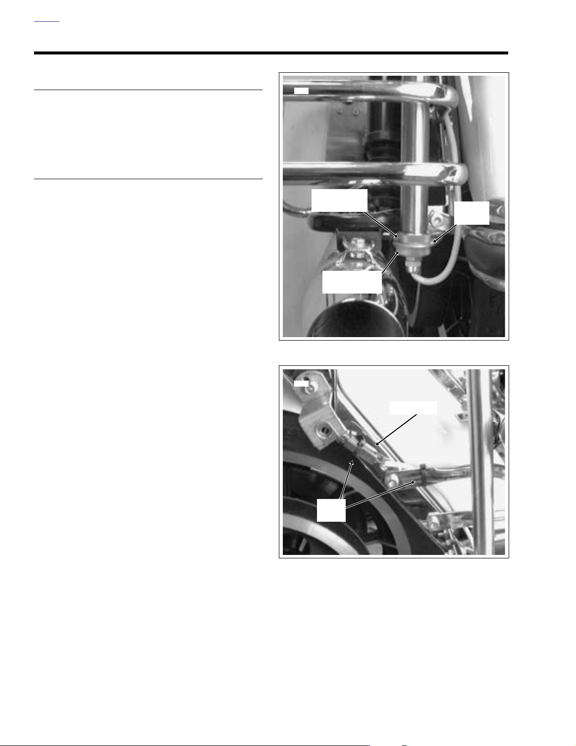
5. Install knurled ring at bottom of pole with the beveled
side up. See Figure 8-18.
6. Insert pole through lower bracket and install second
knurled ring with the beveled side down.
7. Alternately tighten knurled rings to lock position of pole.
8. Mate pin and socket halves of 2-place Deutsch connector. Secure connector and conduit to saddlebag guard
and saddlebag support bracket using
See Figure 8-19.
new
cable straps.
Knurled Ring
(Bevel Up)
6106
Lower
Bracket
Knurled Ring
(Bevel Down)
Figure 8-18. Install Pole Lamp
Connector
8-12 2004 FLT Police: Electrical
Cable
Strap
Figure 8-19. Install Cable Straps
Page 13

HOME
SIREN AND PUBLIC ADDRESS SYSTEM 8.6
GENERAL
The siren and public address (PA) system consists of: amplifier, speaker, microphone, microphone jack, siren, horn/siren
switches and connecting wiring.
The Whelen 100 watt siren amplifier, WS-320, (Part No.
91156- 93) uses a waterproof connector.
Table 8-4. Troubleshooting
PROBLEM
Siren and PA not
operational.
Siren and PA not
operational.
Connector not properly installed. Be sure connector is properly oriented and screw is tight.
Faulty amplifier or speaker. Substitute a known good amplifier and check system func-
CAUSE SOLUTION
TROUBLESHOOTING
If siren and/or PA system are inoperative, refer to the troubleshooting chart below.
Apply wheel bearing grease to connector pins and sockets
to reduce corrosion.
tion. If system is still inoperative, substitute a known good
speaker and check for system operation.
NOTE
If neither an amplifier nor speaker is available, see Section
8.8 SPEAKER, TROUBLESHOOTING in this manual. If
speaker checks “good”, continue at Section 8.7 VOLTAGE
CHECKS, RESISTANCE AND CONTINUITY CHECKS.
Siren functions, PA
not operational.
PA gain control not properly
adjusted.
Inoperative microphone.
Microphone jack or connecting
leads do not provide good electrical connection.
Wrong microphone.
See Section 8.10 SIREN AMPLIFIER, GAIN ADJUST-
MENT.
Substitute a known good microphone. If known good microphone is not available, see Section 8.11 MICROPHONE
AND JACK.
See Section 8.11 MICROPHONE AND JACK.
Some Whelen microphones are electrically different and
cannot be interchanged.
NOTE
Microphones used with WS-320 amplifiers should be
marked 010245648-00.
2004 FLT Police: Electrical 8-13
Page 14
HOME
VOLTAGE CHECKS 8.7
ALL MODELS
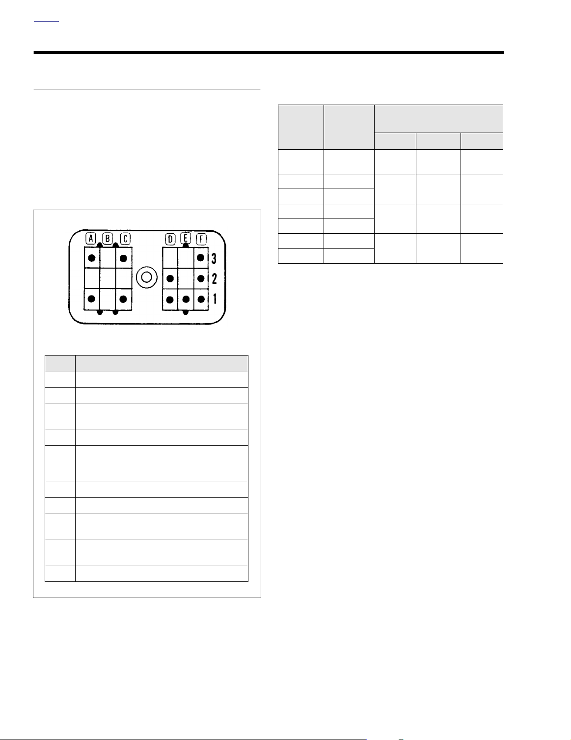
See Figure 8-20, Table 8-5, and the appropriate wiring diagram in Section 8.15 WIRING DIAGRAMS. Measure the voltages at the motorcycle siren harness connector (pins 1C, 2F,
and 1F) as listed in Ta bl e 8-5. The Ignition/Light Key Switch
must at IGNITION while checking voltages. Connect common
or negative lead of voltmeter to a good ground. If voltages
specified in Table 8-4 are not present, refer to applicable wiring diagram to diagnose the problem.
p0011a8x
To Motorcycle Harness
Pin Description
1A Ground (-) to motorcycle
3A Speaker (+)
12 Vdc supply to amplifier.
1C
Present when ignition is on.
3C Speaker (-)
Air horn enabled - 12 Vdc is present when
1D
connected to horn circuit and button is
pushed. See Section 8.12 AIR HORN.
2D Push-to-talk (mic)
1E Mic (-)
Yelp, 12 Vdc is present when siren/horn
1F
switch is ON.
Wail, 12 Vdc is present when siren switch
2F
is ON.
3F Mic (+)
Table 8-5. Voltage Checks at
Motorcycle Siren Harness
Switch
Ignition ON 12 Vdc
Siren OFF
Siren/Horn ON
Siren ON
Siren/Horn OFF
Siren/Horn ON
Siren ON
Switch
Position
VOLTAGE MEASURED AT
1C 2F 1F
Do Not
Measure
Do Not
Measure
Do Not
Measure
PINS
Do Not
Measure
0 Vdc 12 Vdc
12 Vdc 0 Vdc
12 Vdc 12 Vdc
Do Not
Measure
Figure 8-20. Pin Connector
8-14 2004 FLT Police: Electrical
Page 15

HOME
RESISTANCE AND CONTINUITY CHECKS
See Figure 8-20 and Table 8-6 below. Perform checks with
both battery cables removed.
Table 8-6. Resistance/Continuity Checks (Battery Cables Disconnected)
OHMMETER PROBE
LOCATION (PINS)
3A & 3C 6-10 Ohms Speaker coil voice and leads from pin connector to speaker.
3F & 1E Infinity Verifies microphone circuit is not shorted.
Press and hold PTT switch
with probes on pins 2D & 1E.
OHMETER COMPONENT AND WIRE BEING CHECKED
Verifies PTT switch is functioning and two microphone leads from
connector have continuity.
0-1 Ohms
For microphone jack connections, see Figure 8-28. To c heck third
lead, place one probe on pin 3F and the other probe on tip terminal of
microphone jack.
CAUTION
Do not connect ohmmeter probes to a “live” circuit or
ohmmeter will be damaged.
If ohmmeter readings in Table 8-5 are not obtained, refer to
Section 8.15 WIRING DIAGRAMS and diagnose the problem
using the appropriate schematic.
Common probe to ground,
other probe to pin 1A.
0-1 Ohms Checks amplifier to motorcycle ground.
2004 FLT Police: Electrical 8-15
Page 16

HOME
SPEAKER 8.8
TROUBLESHOOTING
If speaker is inoperative, check voice coil impedance as follows:
1. Disconnect speaker leads and measure impedance by
connecting ohmmeter leads to speaker leads.
2. Measured resistance must be 6-10 ohms.
3. Replace speaker if resistance is not within specification.
NOTE
A binding voice coil or torn speaker cone could also cause
speaker to be inoperative. To check for these conditions, connect speaker to shop stereo. If speaker works, it’s functional.
Connector
Bolt
Screw
4579p
REMOVAL
1. Cut two cable straps to release 2-place Deutsch connector and cable from top rail of right side engine guard. Disconnect pin and socket halves. See Figure 8-21.
2. Reaching into speaker horn, remove flange locknuts, flat
washers and rubber washers from top and side bolts.
Pull bolts from speaker horn and mounting bracket.
Remove flat washers and rubber washers between horn
and mounting bracket.
3. Remove bolt to release back of speaker from mounting
bracket.
INSTALLATION
1. Position speaker in mounting bracket aligning holes in
speaker with those in bracket.
2. Loosely install bolt to fasten mounting bracket to back of
speaker. See Figure 8-21.
3. Position rubber washers and flat washers between holes
in horn and mounting bracket, rubber washers against
horn.
NOTE
Be sure the speaker voice coil drain hole is facing down to
provide good drainage. Hole is located 180° from “Made in
USA” logo. See Figure 8-22.
4. Slide bolts through mounting bracket, flat washers, rubber washers and horn. Reaching into speaker horn,
install rubber washers, flat washers and flange locknuts
on bolts.
5. Alternately tighten all fasteners. Rubber washers should
deform slightly when flange locknuts are properly tightened.
Figure 8-21. Speaker (Rear View)
4578p
Drain
Hole
Figure 8-22. Speaker (Bottom View)
6. Mate pin and socket halves of 2-place Deutsch connector. Install two
cable to top rail of right side engine guard.
Use of a high pressure washer on or near speaker can
result in damage.
If speaker center cone is removed to make installation easier,
apply 2-3 drops of Loctite 242 (blue) on center cone screw
and then tighten until snug.
new
cable straps to secure connector and
CAUTION
NOTE
8-16 2004 FLT Police: Electrical
Page 17

HOME
HANDLEBAR SWITCHES 8.9
HORN/SIREN YELP SWITCH
NOTE
Consult the 2004 Touring Models Service Manual (Part No.
99483-04) for assembly/disassembly instructions and general
repair procedures.
Removal
1. See LEFT SIDE HANDLEBAR SWITCHES, DISASSEMBLY, page 8-70 of the 2004 Touring Models Service Manual (Part No. 99483-04).
2. From inside the switch housing, carefully cut cable strap
to free conduit from the turn signal switch bracket.
3. Remove the Phillips screw (with lockwasher) to release
the turn signal switch bracket. Remove the switch
assembly from the housing.
4. Remove the two T8 TORX screws and the Phillips screw
(with lockwasher) to release the lower bracket. Carefully
lift out the bracket so as not to disturb the spring-loaded
ramp on the inboard side of the housing.
5. Carefully remove the keycap disengaging slot from hook
on ramp.
6. While holding down the ramp, pull both switches from the
housing.
7. Cut the wires from the old switches as follows:
●
Ye llow/Black wire: 1-1/4 inches (32 mm)
Orange/White wires: 1-7/8 inches (48 mm)
●
●
Brown/Black wire: 1-1/2 inches (38 mm)
NOTE
Replacement Horn/Siren Yelp Switch wires are cut to length
and partially stripped (Yellow/Black wire: 3-3/4 inches (95
mm); Orange/White wires: 3-1/2 inches (89 mm); Brown/
Black wire: 3-3/8 inches (86 mm).
8. See GENERAL REPAIR PROCEDURES, page 8-78 of
the 2004 Touring Models Service Manual (Part No.
99483-04).
NOTE
If the ramp and spring mechanism becomes loose, install as
follows: Using the blade of a small screwdriver, compress
spring and place in wider portion of channel at bottom of
ramp. Verify that spring is evenly compressed and is not
cocked or skewed. Push spring so that it bottoms in channel.
With tab side of ramp facing inboard and hook end on switch
side of casting, install ramp so that narrow channels engage
pins cast into housing.
Right Handlebar Switch Housings
Upper Switch Housing:
● Engine Start Switch
● Engine Stop Switch: Off/Run
Lower Switch Housing:
● Tu rn-Right Signal Switch
● Front Stoplight Switch
● Pole and Pursuit Lamp Switch:
Off/Aux(iliary)/Purs(uit)
f1236a2x
f1237a2x
Left Handlebar Switch Housings
Upper Switch Housing:
● Siren Switch: On/Off
● Light Switch: Hi(gh) and Lo(w) Beam
Lower Switch Housing:
● Tu rn-Left Signal Switch
● Horn/Siren Yelp Switch
● Clutch/Starter Interlock Switch
Figure 8-23. Police Handlebar Switch Assemblies
2004 FLT Police: Electrical 8-17
Page 18

HOME
Installation
1. Install the switches in the housing with contacts facing
tabs on ramp. For best results, install one switch at a
time. Ribs cast in lower housing hold switches in position.
The Horn switch with the Yellow/Black lead (pivot point
towards rider) is installed at the bottom, while the Siren
Ye lp switch with the Brown/Black lead (pivot point
towards the front) is at the top. Route switch wires in
channel on the outboard side of the ribbed area.
2. Install the keycap engaging slot with hook on ramp.
3. Install lower bracket sliding pin through keycap and
engaging hole in lower casting.
4. Slide T8 TORX screws through holes in lower bracket
and switches and thread into lower casting until snug.
5. Install Phillips screw (with lockwasher), to secure lower
bracket to threaded boss in housing. Verify operation of
Horn and Siren Yelp switches to ensure that both are
spring returned.
6. Install Clutch Interlock Switch in bore of lower switch
housing, if loose.
7. Insert tapered end of
hole in turn signal switch bracket and then feed back
through using the adjacent hole. Reserve the oblong
hole for the bracket screw.
Be sure that all splices are positioned above the turn signal
switch bracket.
8. Place the turn signal switch assembly into the housing
aligning the oblong hole in the bracket with the lower
bracket weld nut. Be sure that bracket is fully seated.
Ta bs on each side are captured in slots cast into switch
housing.
9. Install Phillips screw (with lockwasher) to secure bracket
inside housing.
new
7 inch cable strap into round
NOTE
from end of conduit. Cut any excess cable strap material.
If necessary, bend angular arm of bracket downward to
firmly secure Clutch Interlock Switch in installed position.
14. See LEFT SIDE HANDLEBAR SWITCHES, ASSEMBLY,
page 8-80 of the 2004 Touring Models Service Manual
(Part No. 99483-04).
CLUTCH INTERLOCK SWITCH
NOTE
All Police models have a Clutch Interlock Switch that prevents
the motorcycle from starting (even in Neutral) if the clutch
lever is not pulled in.
Removal
1. See LEFT SIDE HANDLEBAR SWITCHES, DISASSEMBLY, page 8-70 of the 2004 Touring Models Service Manual (Part No. 99483-04).
2. From inside the switch housing, carefully cut cable strap
to free conduit from the turn signal switch bracket.
3. Remove the Phillips screw (with lockwasher) to release
the turn signal switch bracket. Remove the switch
assembly from the housing.
4. Remove the Clutch Interlock Switch from the housing.
5. Cut wires 1/4 inch (6 mm) from old switch. Discard switch
assembly.
NOTE
Replacement Clutch Interlock Switch wires are cut to length
(looking at backside, left side switch wire is 2-1/4 inches (57
mm), right side is 2-3/4 inches (70 mm) and partially stripped.
6. See GENERAL REPAIR PROCEDURES, page 8-78 of
the 2004 Touring Models Service Manual (Part No.
99483-04).
CAUTION
If routed incorrectly, wires may be pinched by casting or
handlebar resulting in switch failure.
10. Loop switch wires so that spliced lengths are positioned
directly over bracket screw.
11. Capturing conduit about 1/4 inch (6 mm) from end,
securely tighten cable strap to draw conduit to bracket.
Remove any excess cable strap material.
12. On opposite side, install second 7 inch cable strap capturing conduit and wire splices. Securely tighten cable
strap to draw splices to conduit. Remove any excess
cable strap material.
13. Route wire bundle to upper switch housing below and
then forward of the main wire harness positioning conduit
in channel next to angular arm of bracket. Secure bundle
to arm placing
8-18 2004 FLT Police: Electrical
new
cable strap 1/4 inch (6 mm)
Installation
1. Install Clutch Interlock Switch in bore of lower switch
housing.
2. Insert tapered end of
hole in turn signal switch bracket and then feed back
through using the adjacent hole. Reserve the oblong
hole for the bracket screw.
Be sure that all splices are positioned above the turn signal
switch bracket.
3. Place the turn signal switch assembly into the housing
aligning the oblong hole in the bracket with the lower
bracket weld nut. Be sure that bracket is fully seated.
Tabs on each side are captured in slots cast into switch
housing.
new
7 inch cable strap into round
NOTE
Page 19

HOME
Clutch Interlock
Switch
p0040a8x
Figure 8-24. Lower Switch Housing
4. Install Phillips screw (with lockwasher) to secure bracket
inside housing.
CAUTION
If routed incorrectly, wires may be pinched by casting or
handlebar resulting in switch failure.
5. Loop switch wires so that spliced lengths are positioned
directly over bracket screw.
6. Capturing conduit about 1/4 inch (6 mm) from end,
securely tighten cable strap to draw conduit to bracket.
Remove any excess cable strap material.
7. On opposite side, install second 7 inch cable strap capturing conduit and wire splices. Securely tighten cable
strap to draw splices to conduit. Remove any excess
cable strap material.
8. Route wire bundle to upper switch housing below and
then forward of the main wire harness positioning conduit
in channel next to angular arm of bracket. Secure bundle
to arm placing
of conduit. Cut any excess cable strap material. If necessary, bend angular arm of bracket downward to firmly
secure Clutch Interlock Switch in installed position.
new
cable strap 1/4 inch (6 mm) from end
PURSUIT/AUXILIARY SWITCH
Removal
1. See RIGHT SIDE HANDLEBAR SWITCHES, DISASSEMBLY, page 8-70 of the 2004 Touring Models Service
Manual (Part No. 99483-04).
2. From inside the switch housing, carefully cut cable strap
to free conduit from the turn signal switch bracket.
3. Remove the Phillips screw (with lockwasher) to release
the turn signal switch bracket. Remove the switch
assembly from the housing.
4. Remove the two T8 TORX screws and the Phillips screw
(with lockwasher) to release the lower bracket. Remove
the bracket from the housing.
5. Pull both switches from the housing.
6. Cut the wires from the old switches as follows:
Gray/Black wire: 1-1/2 inches (38 mm)
●
●
Orange/Violet wires: 1-7/8 inches (48 mm)
Green/Red wire: 1-1/4 inches (32 mm)
●
NOTE
Replacement Pursuit/Auxiliary Switch wires are cut to length
and partially stripped (Gray/Black wire: 2 inches (51 mm);
Orange/Violet wires: 1-7/8 inches
1-3/4 inches (45 mm).
7. See GENERAL REPAIR PROCEDURES, page 8-78 of
the 2004 Touring Models Service Manual (Part No.
99483-04).
8. Move keycap to the OFF position. Install the switches in
the housing with contacts facing the recessed area on
the ramp. Ribs cast in lower housing hold switches in
position.
The Auxiliary switch with the Gray/Black lead is installed
at the bottom, while the Pursuit switch with the Green/
Red lead is at the top. Route switch wires into corner
space outside of the ribbed area.
If the keycap and ramp mechanism requires replacement,
install as follows: Slide ramp upward to remove from keycap
shaft. Remove keycap from switch housing. Install spring into
hole on inboard side of
spring. Use a small amount of grease to hold ball in place.
Install keycap so that ball engages detente in switch housing.
Slide ramp over keycap shaft so that tongues on ramp
engage grooves in keycap shaft.
new
Installation
(48 mm)
NOTE
keycap. Position ball on end of
; Green/Red wire:
9. See LEFT SIDE HANDLEBAR SWITCHES, ASSEMBLY,
page 8-80 of the 2004 Touring Models Service Manual
(Part No. 99483-04).
1. Install lower bracket with the weld nut side down.
2. Slide the T8 TORX screws through holes in lower bracket
and switches and thread into lower casting until snug.
2004 FLT Police: Electrical 8-19
Page 20

HOME
3. Install Phillips screw (with lockwasher), to secure lower
bracket to threaded boss in housing. Work Auxiliary and
Pursuit switches to ensure smooth operation.
4. See Figure 8-25. Insert tapered end of
new
7 inch cable
strap into round hole in turn signal switch bracket and
then feed back through using the adjacent hole. Reserve
the oblong hole for the bracket screw.
NOTE
Be sure that all splices are positioned above the turn signal
switch bracket.
5. Place the turn signal switch assembly into the housing
aligning the oblong hole in the bracket with the lower
bracket weld nut. Be sure that bracket is fully seated.
Ta bs on each side are captured in slots cast into switch
housing.
6. Install Phillips screw (with lockwasher) to secure turn signal switch bracket inside housing.
7 Inch
Cable Strap
Bracket
Right Turn
Signal Switch
CAUTION
If routed incorrectly, wires may be pinched by casting or
handlebar resulting in switch failure.
7. Loop switch wires so that spliced lengths are positioned
directly over bracket screw.
8. Capturing conduit about 1/4 inch (6 mm) from end,
securely tighten cable strap to draw conduit to bracket.
Remove any excess cable strap material.
9. On opposite side, install second 7 inch cable strap capturing conduit and wire splices. Securely tighten cable
strap to draw splices to conduit. Remove any excess
cable strap material.
f1294x2x
Figure 8-25. Insert Cable Strap in Switch Bracket
10. Route wire bundle to upper switch housing in channel
next to angular arm of bracket. Secure bundle to arm
placing
new
cable strap 1/4 inch (6 mm) from end of conduit. Cut any excess cable strap material. If necessary,
bend angular arm of bracket downward to firmly secure
Front Stoplight Switch in installed position.
11. See RIGHT SIDE HANDLEBAR SWITCHES, ASSEMBLY, page 8-80 of the 2004 Touring Models Service Manual (Part No. 99483-04).
8-20 2004 FLT Police: Electrical
Page 21

HOME
4577p
4575p
Adjustment Screw
(Under Access Hole Screw)
SIREN AMPLIFIER 8.10
AMPLIFIER
Part No. /Description
91156-93 Whelen 100 Watt (WS-320) Siren Amplifier
REMOVAL
See Figure 8-26. The Whelen amplifiers are mounted to the
mounting bracket in front of the left saddlebag with screws
and washers.
1. Pull back rubber boot.
2. Loosen connector screw and disconnect connector.
3. Remove mounting screws.
INSTALLATION
1. Position amplifier as shown in Figure 8-26.
2. Install mounting screws and tighten to 6 ft-lbs (8 Nm).
3. Plug in the connector and tighten connector screw.
4. Install rubber boot.
GAIN ADJUSTMENT
NOTE
The Public Address (PA) amplifier gain is set at the manufacturer and normally does not require adjustment. If it has feedback, low volume or distortion, adjust the gain as follows:
1. Remove access screw to expose the internal adjusting
screw. See Figure 8-27.
2. Press Push-To-Talk switch on microphone, speak into
microphone in normal manner and while speaking, carefully turn internal adjusting screw, with a proper size
screwdriver, to obtain maximum distortion free output.
3. Replace access screw.
Figure 8-26. Whelen Amplifier Mounting
Figure 8-27. PA Gain Adjustment Screw
2004 FLT Police: Electrical 8-21
Page 22

HOME
MICROPHONE AND JACK 8.11
MICROPHONE
Troubleshooting
1. To verify that Push-To-Talk (PTT) switch is functioning
properly, connect probes of ohmmeter to tip and ring of
microphone plug. See Figure 8-28.
2. With PTT switch off (not depressed) there must be no
continuity.
3. Depress PTT switch. Ohmmeter must read 0-1 ohm.
Replace microphone if there is no continuity.
REMOVAL
1. FLHTP: Remove outer fairing. See OUTER FAIRING/
WINDSHIELD, REMOVAL, page 2-120 of the 2004 Touring Models Service Manual (Part No. 99483-04).
FLHP: Remove headlamp assembly. See HEADLAMP
ASSEMBLY, REMOVAL, page 8-25 of the 2004 Touring
Models Service Manual (Part No. 99483-04).
2. Remove nut and washer to release microphone jack.
3. Unsolder leads from jack terminals.
INSTALLATION
1. Solder leads to jack terminals as shown in Figure 8-28.
2. Install microphone jack and secure with washer and nut.
3. FLHTP: Install outer fairing. See OUTER FAIRING/
WINDSHIELD, INSTALLATION, page 2-120 of the 2004
Touring Models Service Manual (Part No. 99483-04).
FLHP: Install headlamp assembly. See HEADLAMP
ASSEMBLY, INSTALLATION, page 8-25 of the 2004
Touring Models Service Manual (Part No. 99483-04).
p0013a8x
4
3
5
R
W
BE
To Pin Connector
2
1
Microphone Jack
6
Microphone Plug
1. Sleeve
2. Ring
3. Tip
Microphone Plug
Microphone Jack
4. Ring
5. Sleeve
6. Tip
8-22 2004 FLT Police: Electrical
Figure 8-28. Microphone and Jack Connections
Page 23

HOME
AIR HORN 8.12
ENABLING AIR HORN
1. FLHTP: Remove outer fairing. See OUTER FAIRING/
WINDSHIELD, REMOVAL, page 2-120 of the 2004 Touring Models Service Manual (Part No. 99483-04).
FLHP: Remove headlamp assembly. See HEADLAMP
ASSEMBLY, REMOVAL, page 8-25 of the 2004 Touring
Models Service Manual (Part No. 99483-04).
2. Locate the gray 12-place Deutsch connector for the left
side handlebar switch controls [24]. See Figure 8-29 for
FLHTP models, Figure 8-30 for FLHP models.
3. Remove the secondary lock from the socket half of the
connector and proceed as follows:
a. Pull seal pin from cavity 11.
b. Remove Y/BK wire from cavity 6.
c. Install Y/BK wire in cavity 11. See Figure 8-31.
d. Push seal pin into cavity 6.
NOTE
For instructions on properly removing and installing wire terminals, see APPENDIX B.1, DEUTSCH ELECTRICAL CONNECTORS, REMOVING/INSTALLING SOCKETS, page B-1
of the 2004 Touring Models Service Manual (Part No. 99483-
04).
4. Place a rag in the speaker cone to reduce volume. Turn
the Ignition/Light Key Switch to IGNITION and test operation of air horn.
Left Handlebar Controls [24]
(Gray)
p0118x8x
Figure 8-30. Headlamp Nacelle (FLHP)
MOVE Y/BK WIRE TO CAVITY
11 IF USING WHELEN SIREN
AMPLIFIER & AIR HORN
FUNCTION IS DESIRED
p0042c8x
Left Handlebar Controls [24]
(Gray)
[24B]
(GRAY)
1
O/W
2
Y
3
BE
4
W
W/V
Y/BK
BK/R
BK/R
PK/BK
TN/BK
Y/BK
FROM
5
MAIN
6
HARNESS
7
[24A]
8
9
10
11
12
CLUTCH
LOCKOUT SWITCH
SIREN OFF/RUN
SWITCH
HEADLAMP HI/LO
SWITCH
LEFT
DIRECTIONAL
SWITCH
HORN/SIREN
SWITCH
Figure 8-31. Enabling the Air Horn (All Models)
5. FLHTP: Install outer fairing. See OUTER FAIRING/
WINDSHIELD, INSTALLATION, page 2-120 of the 2004
p0058x8x
Touring Models Service Manual (Part No. 99483-04).
FLHP: Install headlamp assembly. See HEADLAMP
Figure 8-29. Inner Fairing (FLHTP)
ASSEMBLY, INSTALLATION, page 8-25 of the 2004
Touring Models Service Manual (Part No. 99483-04).
2004 FLT Police: Electrical 8-23
Page 24

HOME
TOUR-PAK 8.13
GENERAL
i03730
The Tour-Pak Kit (White- Part No. 53238-01; Black- Part No.
53239-01) is designed for installation on both FLHP and
FLHTP model motorcycles and is available from your HarleyDavidson Dealer.
1WARNING1WARNING
The rider’s safety depends on the correct installation of
this kit. If the following installation procedures are not
within your capabilities, or if you do not have the correct
tools, have your Harley-Davidson dealer perform this
installation. Failure to do the installation correctly could
result in death or serious injury.
Phillips Screws
with Washers
Luggage
Rack Spacer
Hex Head
Screws
INSTALLATION
1. See Figure 8-32. Remove the five hex head cap screws
and two smaller Phillips screws (with washers) securing
existing radio tray to mounting rail. Leave the two rectangular license plate spacers and set aside three remaining spacers. Discard screws and washers, but save nuts
for installation later. Discard radio tray.
2. See Figure 8-33. Carefully remove Tour-Pak assembly
and hardware from shipping container. Open Tour-Pak.
Remove the three nuts securing the power supply
mounting plate to the bottom of the Tour-Pak. Save for
reinstallation.
3. Note connector locations for reinstallation and disconnect the strobe head connectors from the power supply.
4. See Figure 8-34. Set power supply aside temporarily.
Raise and position (lean) the mounting plate up against
the front side of Tour-Pak to provide access to the TourPak permanent mounting holes. If necessary, use a
cable strap to hold plate in place. Temporarily set TourPak assembly aside.
Figure 8-32. Remove Radio Tray and Hardware
Strobe Head
Connectors
Nut
Nut
Figure 8-33. Remove Plate Securing Power Supply
i03732
i03731
Nut
8-24 2004 FLT Police: Electrical
Power Supply
Mounting Plate
Leaning Toward
Front of Tour-Pak
Figure 8-34. Provide Room For Mounting Tour-Pak
Page 25

HOME
i03733
Trim Panel
Nuts
Seat Pin
Cut Cable
Straps
Securing
Pole Lamp
Harness
i03734
Tour-Pak Mounting
Bolts (with Washers)
Washers
and Nuts
License Plate
Bracket Spacer
Luggage
Rack Spacer
i03735
i03736
Spacer
Mounting
Block
Washer
and Nut
5. See Figure 8-35. Remove the quick release seat pin clip
from the seat pin and pivot the seat forward as far as
possible. It may be necessary to tie or brace seat in the
full forward position.
6. Remove the two nuts and washers securing the trim
panel assembly to the fender and remove panel. Save
hardware and panel for reinstallation.
1WARNING1WARNING
To protect against shock and accidental start-up of vehicle, disconnect the negative battery cable before proceeding. Inadequate safety precautions could result in
death or serious injury. (00048a)
1WARNING1WARNING
Always disconnect the negative battery cable first. If the
positive cable should contact ground with the negative
cable installed, the resulting sparks may cause a battery
explosion which could result in death or serious injury.
(00049a)
7. Disconnect battery cables, negative battery cable first.
Figure 8-35. Remove Trim Panel
8. Cut the two cable straps securing the pole lamp harness
to the support rail. Discard cable straps. Route pole lamp
harness away from Tour-Pak mounting area.
9. See upper frame of Figure 8-36. Return to the Tour-Pak.
Using parts from kit, pre-install four long hex head bolts
with washers from inside bottom of Tour-Pak at four permanent mounting holes.
10. Raise the Tour-Pak up and position onto rack with four
mounting bolts aligned with four holes in support rail (two
on each side).
See lower frame of Figure 8-36. Make sure the two
license plate bracket spacers remain in position and
bolts can pass through them. Obtain the two rectangular
luggage rack spacers and four nuts saved from step 2.
Obtain four new washers from kit and loosely install
washers and nuts to secure Tour-Pak to support rail.
11. Obtain rear mounting block (with1 hole), hex head bolt
and two flat washers from kit. Also obtain rectangular
spacer and nut saved from step 1.
12. See Figure 8-37. Install washer to bolt and position bolt
above hole at rear center Tour-Pak above rear block
mounting position.
13. Orient rear mounting block (with hole running vertical)
and position between recessed area of Tour-Pak (near
center) and rail support. Install bolt through Tour-Pak,
rear block and rail, then loosely Install spacer followed by
washer and nut.
Figure 8-36. Install Tour-Pak Mounting Hardware
Figure 8-37. Install Tour-Pak Mounting Block
2004 FLT Police: Electrical 8-25
Page 26

HOME
14. Obtain the remaining mounting block (with 2 holes), two
long Phillips and two flat washers from kit.
15. See Figure 8-38. Install flat washers to Phillips screws
and position screws above two holes near front center of
To ur-Pak above front mounting block position.
16. Position block (with holes running vertical) between TourPak and air tank mounting bracket. Install screws
through Tour-Pak and mounting block and thread into air
tank mounting bracket. Tighten screws to 22 in-lbs (2.5
Nm).
17. Return to mounting hardware installed in Steps 9
through 15 and alternately tighten to 60-84 in-lbs (6.8-
9.5 Nm).
18. See Figure 8-39. Reposition power supply onto mounting
plate and reinstall the three nuts removed in step 3 to
provide access for mounting Tour-Pak. Obtain two more
nuts from kit and install to remaining mounting plate
studs. Tighten nuts to 80 in-lbs (9.0 Nm).
19. Reconnect the strobe head (male to female) connectors
disconnected in step 4.
Front
Air Tank
Mounting
Mounting
Block
Bracket
i03737
Figure 8-38. Install Tour-Pak Front Mounting Block
i03738
Nut
NOTE
When performing the next few steps, install battery mounting
bracket, battery strap and battery only. Do NOT connect battery terminals at this time.
20. See Figure 8-40. Loosely assemble battery mounting
bracket with bolt, washers and nut obtained from kit.
21. Orient and position battery behind mounting bracket as
shown. Loosely install battery strap using two bolts, four
washers and two nuts from kit.
22. Make sure battery is centered and mounting bracket is
positioned properly. While pushing mounting bracket forward, tighten bracket hardware to 120-144 in-lbs (13.6-
16.3 Nm). Return to battery strap hardware and tighten
to 120-144 in-lbs (13.6-16.3 Nm).
Nut
Nut
Strobe
Connectors
Nut
Figure 8-39. Install Power Supply Mounting Plate and
Reconnect Strobe Heads
Battery
Battery
Strap
i03739
Mounting
Bracket
Nut
Nut
8-26 2004 FLT Police: Electrical
Washer
Washer
Figure 8-40. Install Battery Mounting Bracket and Battery
Page 27

HOME
i03739
Positive
Cable
Negative
Cable
i03741
2-Pin
Connector
Control
Harness
PNA
Accessory
Connector
i03742
Maxi-Fuse
Positive Cable
Radius to Prevent
Terminal Kinking
Pole Lamp
Harness
Connector
23. See Figure 8-41. Locate positive and negative battery
cables in Tour-Pak. Make sure cables are not touching
each other or anything metal in the Tour-Pak.
24. See Figure 8-42. Route control harness (from Tour-Pak)
along left upper frame tube to PNA accessory connector
in space immediately in front of motorcycle battery.
25. Connect control harness to PNA accessory connector.
26. Locate the two-pin connector originally routed to pole
lamp and connect to the two-pin connecter coming from
To ur-Pak.
NOTE
Prior to installing positive battery terminal to battery post,
locate insulated end of positive battery cable (directly after
maxi-fuse) and bend a 90 degree radius into the cable as
shown. This will keep the terminal from kinking when installing terminal to battery post.
1WARNING1WARNING
Always connect the positive battery cable first. If the positive cable should contact ground with the negative cable
installed, the resulting sparks may cause a battery explosion which could result in death or serious injury.
(00068a)
Figure 8-41. Positive and Negative
Tour-Pak Battery Cables
27. See Figure 8-43. Route the positive battery cable with
Maxi-fuse as shown and loosely install positive battery
terminal over existing terminal to battery positive post.
Tu ck the Maxi-Fuse along with the pole lamp harness
down into the space between the battery and the left
upper frame tube as shown. Tighten terminal to 30 in-lbs
(3.4 Nm).
28. Route the negative battery cable around the front of the
battery and install terminal over existing terminal to negative battery post. Tighten terminal to 30 in-lbs (3.4 Nm).
Figure 8-42. Install Tour-Pak Harness and
2-Pin Connectors
Figure 8-43. Install Tour-Pak Battery Cables
to Motorcycle
2004 FLT Police: Electrical 8-27
Page 28

HOME
29. See Figure 8-44. Install cable strap to secure Tour-Pak
Harness to mounting rail.
30. See Figure 8-45. Reinstall trim panel to fender using nuts
and washers saved from step 7.
31. Reinstall trim panel cover to protect battery and wiring.
32. Pivot seat downward and lower until it engages seat pin
completely. Install quick release seat pin clip to fully
secure seat.
1WARNING1WARNING
After installing seat, pull upward on front of seat to be
sure it is locked in position. If seat is loose, it could shift
position during vehicle operation and startle the rider,
causing loss of control and death or serious injury.
(00070a)
1WARNING1WARNING
i03743
Tour-Pak
Harness
Figure 8-44. Secure Tour-Pak Harness to Mounting Rail
Cable
Strap
Always connect the positive battery cable first. If the positive cable should contact ground with the negative cable
installed, the resulting sparks may cause a battery explosion which could result in death or serious injury.
(00068a)
33. See Figure 8-46. Return to Tour-Pak and locate positive
and negative battery cables. Route positive battery terminal to battery and install terminal to battery post.
Tighten terminal to 30 in-lbs (3.4 Nm).
34. Route negative battery terminal to negative battery post
and install terminal. Tighten terminal to 30 in-lbs (3.4
Nm).
35. Close Tour-Pak and test strobe lights for proper operation.
Trim Panel
i03744
Figure 8-45. Reinstall Trim Panel
Negative Post
and Terminal
Positive Post
and Terminal
8-28 2004 FLT Police: Electrical
i03740
Figure 8-46. Install Tour-Pak Battery Terminals
Page 29

HOME
ELECTRICAL CONNECTOR LOCATIONS 8.14
Table 8-7. FLHTP Wire Harness Connectors
No. Description Type Location Fig.
Left Handlebar Controls-
[24]
Air Horn Option
[57] Siren/PA Speaker 2 - Place Deutsch Top Rail of Engine Guard (Right Side) -
[59] Rear Pole Lamp 2 - Place Deutsch Under Luggage Rack (Left Side) -
[69] Pursuit Flasher Relay Connector Inner Fairing - Inboard of Left Fairing Bracket 8-47
[70] Siren Amplifier Harness 12 -Place Deutsch Inner Fairing - Left Fairing Support Brace 8-47
[72] Siren Amplifier 18 - Place Packard Top Rail of Saddlebag Guard (Left Side) -
[73] Pursuit Lamps 2 - Place Multilock (White) Inner Fairing - Next to Top Fork Bracket 8-47
[108] Tachometer 6 - Place Packard Inner Fairing - Back of Tachometer 8-47
1. Tachometer [108]
2. Left Handlebar Controls [24]
3. Siren Amplifier Harness [70]
4. Pursuit Flasher [69]
5. Pursuit Lamps [73] (White)
12 - Place Deutsch (Gray) Inner Fairing - Left Fairing Support Brace 8-47
3
1
2
p0058x8x
4
5
Figure 8-47. Inner Fairing (FLHTP)
2004 FLT Police: Electrical 8-29
Page 30

HOME
Table 8-8. FLHP Wire Harness Connectors
No. Description Type Location Fig.
[24]
Left Handlebar Controls
Air Horn Option
12 - Place Deutsch (Gray) Inside Headlamp Nacelle 8-48
[57] Siren/PA Speaker 2 - Place Deutsch Top Rail of Engine Guard (Right Side) -
[59] Rear Pole Lamp 2 - Place Deutsch Under Luggage Rack (Left Side) -
[69] Pursuit Flasher Relay Connector Under Left Side Cover -
[72] Siren Amplifier 18 - Place Packard Top Rail of Saddlebag Guard (Left Side) -
[73] Pursuit Lamps 2 - Place Multilock (White) Inside Headlamp Nacelle 8-48
[108] Tachometer 3 - Place Deutsch Inside Headlamp Nacelle 8-48
p0118x8x
Left Handlebar Controls [24] (Gray)
Air Horn Option
Pursuit Lamps [73]
8-30 2004 FLT Police: Electrical
Tachometer [108]
Figure 8-48. Headlamp Nacelle (FLHP)
Page 31

HOME
WIRING DIAGRAMS 8.15
SUBJECT PAGE NO.
FLHTP
Main Harness . . . . . . . . . . . . . . . . . . . . . . . . . . . . . . . . . . . . . . . . . . . . . . . . . . . . . . . . 8-33
Interconnect Harness . . . . . . . . . . . . . . . . . . . . . . . . . . . . . . . . . . . . . . . . . . . . . . . . . . 8-34
Electronic Fuel Injection (EFI) Harness . . . . . . . . . . . . . . . . . . . . . . . . . . . . . . . . . . . . 8-35
Ignition Switch . . . . . . . . . . . . . . . . . . . . . . . . . . . . . . . . . . . . . . . . . . . . . . . . . . . . . . . 8-36
Tail Lamp, Pursuit Lamps, Directional Lamps and Fender Tip Lamps . . . . . . . . . . . . . 8-36
Starting and Charging . . . . . . . . . . . . . . . . . . . . . . . . . . . . . . . . . . . . . . . . . . . . . . . . . . 8-37
Handlebar Controls, Speedometer, Tachometer and Indicator Lamps . . . . . . . . . . . . 8-38
Siren Amplifier and Strobe Harness . . . . . . . . . . . . . . . . . . . . . . . . . . . . . . . . . . . . . . . 8-39
Optional Strobe System . . . . . . . . . . . . . . . . . . . . . . . . . . . . . . . . . . . . . . . . . . . . . . . . 8-44
FLHP, FLHPE
Main Harness . . . . . . . . . . . . . . . . . . . . . . . . . . . . . . . . . . . . . . . . . . . . . . . . . . . . . . . . 8-40
Electronic Fuel Injection (EFI) Harness . . . . . . . . . . . . . . . . . . . . . . . . . . . . . . . . . . . . 8-41
Starting and Charging . . . . . . . . . . . . . . . . . . . . . . . . . . . . . . . . . . . . . . . . . . . . . . . . . . 8-42
Handlebar Controls, Indicator Lamps, Tail Lamp, Pursuit Lamps,
Directional Lamps, Accessory/Spot Switch, Speedometer and Tachometer . . . . . . . . 8-43
Siren Amplifier and Strobe Harness . . . . . . . . . . . . . . . . . . . . . . . . . . . . . . . . . . . . . . . 8-39
Optional Strobe System . . . . . . . . . . . . . . . . . . . . . . . . . . . . . . . . . . . . . . . . . . . . . . . . 8-44
NOTE
Harness Part No.’s may be included on some wiring diagrams. Use these numbers for
reference only. ALWAYS REFER TO THE 2004 FLT POLICE MODELS PARTS CATALOG
(Part No. 99545-04) WHEN ORDERING WIRING HARNESSES.
2004 FLT Police: Electrical 8-31
Page 32

HOME
NOTES
8-32 2004 FLT Police: Electrical
Page 33

HOME
TSM/TSSM
VSS/SERIAL DATA LINK
SECURITY INDICATOR
LEFT TURN FEED
RIGHT TURN FEED
RIGHT TURN SW INPUT
LEFT TURN SW INPUT
START RELAY CONTROL
IGNITION ENABLE
ALARM SIGNAL
TURN SIGNAL/
TURN SIGNAL SECURITY
MODULE
TO
IGNITION/EFI
HARNESS
[8A]
(GY)
TO
INTERCONNECT
HARNESS
[1A]
(BK)
TO
INTERCONNECT
HARNESS
[2A]
(GY)
TO
INTERCONNECT
HARNESS
[15A]
OIL
PRESSURE
SENDER
[139A]
BATTERY
IGNITION
GROUND
[30A]
12
BK
11
LGN/V
10
CRANK POSITION
9
8
7
6
GY
5
W/GN
4
3
BE/O
W/BK
2
BN/GY
1
12
11
10
9
8
7
6
5
4
3
2
1
12
11
10
9
8
7
6
5
4
3
2
1
D
C
B
A
SENSOR
BK
R
[79A]
D C B A
BK
R
[8B]
O/GY
GN/R
W/V
W/BN
O/BE
BN
V
W/BK
O/W
O/R
GY
O/V
O
[1B]
[2B]
[15B]
R
BK
W/GN
TN
GN/Y
BN/GN
O
Y/BK
Y/W
BN/GY
BE
BK/R
R/BE
BK
BK/GN
BE
R/O
[139B]
1
2
3
4
5
6
7
8
9
10
11
12
2
1
BN/GN
GN/Y
BN/GY
GY
LGN/V
BN/V
V
BN
W/BN
W/V
TN/GN
LGN/BN
BK
(GY)
2
1
[79B]
THROTTLE
ROLL-OFF
SWITCH
[75A]
[75B]
[30B]
Y/V
[75C]
[75D]
O/V
FUEL
PUMP
FUEL PUMP
ASSEMBLY
IN TANK
AT TOP OF TANK
70369-02
FUEL TANK
HARNESS
HORN
[122 ]
Y/BK
BK
[13B]
[13A]
[131]
TN
BK
[141A]
123
12
3
BK
Y/W
O/GY
123
3
12
BK
Y/W
O/GY
NEUTRAL
SWITCH
EFI
[141B]
BK
RH GND
STUD
- FRAME GROUND -
LH GND
STUD
(BK)
[12B]
TOUR-PAK
R/BE
O/W
REAR
STOPLIGHT
SWITCH
[121]
BK
BE
R/Y
321
[12A]
TO INTERCONNECT
BN/V
[156B]
(GY)
BK
BE/BK
OPTIONAL
SECURITY
SIREN
[142A]
POWER
SIGNAL
GROUND
A B C
BKBK/GN
BN/GY
LGN/BN
BK
[142B]
MAIN POWER
AT S TARTER
V/Y
BK
ABCDEFGHJ
W/BE
R/GN
LGN/V
[156A]
12
3456
ON/OFF
SET/COAST
RESUME/ACCEL
GROUND
THROTTLE ROLL-OFF
CRUISE CONTROL MODULE
[5B]
R
O/V
W/GN
GN/R
R/BE
BE/O
K
IGNITION
SET LAMP
BRAKE SIGNAL
SPEED SIGNAL
ENGINE SPEED
40A
MAXI-FUSE
A B
R
R
[17B]
[17A]
VOLTAGE
REGULATOR
[77A]
R
O/V
R/Y
R/BE
BK
O
BE
BE
GY
O/V
O/W
O/R
BN/GY
O/BE
4E
3F
3E
4F
1B 1A
1D 1C
1H 1G
1F 1E
4D 4C
2B
2D 2C
2F 2E
3B 3A
R/O
3D 3C
4B 4A
[7A]
12345678
CONNECTOR
[64B]
3
5
2
1
INSTRUMENTS - 15A
LIGHTS - 15A
HEADLAMP - 15A
IGNITION - 15A
IGN - 2A MAX
P&A
BRAKE/PURSUIT - 15A
ACCESSORIES - 15A
P& A - 15A
RADIO MEM - 15A
BATTERY - 15A
SIREN - 10A
BK
BK
BN
O/W
R/Y
V
TO REAR
LIGHTING
[7B]
B+
BE
[160B]
R
BK
BRAKE
RELAY
2A
TO
IGNITION
SWITCH
[33B]
A
BCD
R/GY
R
R/BK
R/BK
R/BK
R/GY
R
O/GN
KEYSWITCH IGN RELAY
[33A]
R/BK
BK
O
R/Y
O/R
[4A]
(BK - LOCATED UNDER
85
8630
BK
R/BK
START RELAY
8630 87A
85
TN/GN
BK/R
START
SOLENOID
4
3
ACCESSORY
2
CONNECTOR
1
87A
R
O/GN
R/GY
[126A]
[126B]
R/BK
[123A]
[123B]
GN
[128B]
SEAT)
f2227o8x
2004 FLHTP, DOMESTIC and INTERNATIONAL Models,
Main Harness
8-33
Page 34

HOME
TO
RIGHT-HAND
CONTROLS
[22B]
PURSUIT
FLASHER
TO MAIN HARNESS
[2B]
[2A]
Y/W
345
BE
BN/GY
2
1
BK/R
(GY)
R/BE
10
11
9
X
P
L
(BK)
[22A]
1
O/W
2
R/BE
3
4
5
6
7
8
9
10
11
12
G/Y
W/BK
W/BN
BK/R
O/V
GY/BK
GN/R
GY/V
GY/BN
GY/BK
12
[69B] [69A]
BK
678
/Y
N
O/R
TN
G
Y/BK
TO MAIN HARNESS
1011
12
9
O/PK
W/BN
W/V
BN
[1B]
V
W/BK
O/W
O/R
FUEL
12345678
[1A]
(BK)
/V
/Y
O
O
G
[116A] [116B]
+
1
O
1
2
S
[117A]
3
2
[117B]
O
BK
Y/W
VOLTMETER
[110A] [110B]
+
BK
O
1
2
S
[111A]
3
1
2
[111B]
BK
O
BK
TO
LEFT-HAND
CONTROLS
[24B]
TO
INDICATOR
LAMPS
[21B]
HEADLAMP
[38]
GND
10
11
12
10
(GY)
[24A]
1
2
3
4
5
6
7
8
9
[21A]
1
2
3
4
5
6
7
8
9
LO-BEAM
HI-BEAM
O/W
Y
BE
W
W/V
Y/BK
BK/R
BK/R
PK/BK
TN/BK
Y/PK
BN
GN/Y
W
V
BK
O
TN
O
BK
BK
(BK)
BK
(BK)
[70A]
[15A]
(BK)
1
2
3
4
5
6
AMPLIFER
7
HARNESS
8
9
10
11
12
A
B
HARNESS
C
D
TO
SIREN
[70B]
TO MAIN
[15B]
O/PK
TN/BK
PK/BK
Y/PK
GN/R
BK
BK
BE
BK
O/W
BK
CIGAR LIGHTER
BK
Y
W
(BK)
[31A]
BK
123456
TURN SIGNALS
BE
BN
FRONT
V
BK
BE
GY/BN
12
PURSUIT
LAMPS
(WE)
GY/V
[73A]
[32A]
BE
12
FENDER
TIP LIGHT
(BK)
[156B]
LGN/V
1234
MAIN
HARNESS
(GY)
(BK)
[39B] [108B]
1
O
LGN/V
34
2
IGNITION
DATABUS
BN/GY
67
5
NC
BATTERY
SECURITY LP
O/V
ACCESSORY
BK
8
GROUND
Y/W
BK
BK
12
10
11
9
NC
FUEL LEVEL
TRIP SWITCH
TRIP SWITCH
NC
BK
BK
(GY)
O
LGN/V
2
1
3
DATABUSNCPURSUIT
IGNITION
4
GN/R
5
O/V
BN/GY
6
BATTERY
ACCESSORY
7
BK
8
GROUND
9
NC
10
NC
12
11
NC
CRUISE ACTIVE
CRUISE ENABLE
[132B]
RPM x 100
SPEEDOMETER
2004 FLHTP, DOMESTIC and INTERNATIONAL Models,
Interconnect Harness
TRIP
RESET
SWITCH
[154A]
TACHOMETER
f2227c8x
8-34
Page 35

HOME
[83A]
FRONT SPARK
PLUG
ABC
(REAR)
(FRONT)
(+12VDC)
W/GN
IGNITION
R/W
BK
[65B]
(BK)
COIL
(CARB)
REAR SPARK PLUG
R
A
A
B
B
C
BK
C
[65A]
VEHICLE
SPEED SENSOR
+5V DC
W
OUTPUT
SENSOR
POWER
COIL RR
ION SENSE
ABCD
GROUND
COIL FRT
[83A]
IGNITION
COIL
(EFI)
FUEL INJECTED
VEHICLES
EFI OVERLAY: 70233-04
ELECTRONIC
CONTROL
MODULE
ALDL & FLASH PIN
CHECK ENG LP
TAC H OUTPUT
SYSTEM RELAY
SERIAL DATA LINK
ENGINE TEMPERATURE
INTAKE AIR TEMPERATURE
OXYGEN SENSOR A
ANALOG INPUT
POWER GROUND
CRANK POS. SENSOR (-)
5V SENSOR POWER
FREQUENCY INPUT
IDLE AIR CNTL MOTOR
IDLE AIR CNTL MOTOR
THROTTLE POS SNSR INPUT
OXYGEN SENSOR B
MAP SENSOR INPUT
5V SENSOR GROUND
CRANK POS. SNSR (+)
SWITCH INPUT (unused)
VEHICLE SPEED INPUT
IDLE AIR CNTL MOTOR
IDLE AIR CNTL MOTOR
COIL REAR
SWITCH POWER
DIGITAL GROUND
INJECTOR REAR
OUTPUT (unused)
INJECTOR FRONT
OUTPUT (UNUSED)
ION SENSE
POWER GROUND
COIL FRONT
CONSTANT POWER
DIGITAL POWER
[78A]
REAR
INJECTOR
AB
[85B]
Y/GN
GN/GY
BK/W
SENSOR
[89B]
INTAKE
AIR
TEMP.
AB
LGN/Y
BK/W
[83B]
IGNITION
COIL
ABCD
Y/BE
Y/GN
GY/BE
BE/O
ENGINE
TEMP.
SENSOR
DATA
(GY)
[91A]
[78B]
123456789101112131415161718192021222324252627282930313233343536
123456789101112131415161718192021222324252627282930313233343536
LGN/R
PK
GN/O
LGN/V
PK/Y
LGN/Y
BK
Y/BE
BK+
W/BK
R/W
BK/O
BK/PK
GN/GY
LINK
12
LGN/R
34
BK
GY
LGN/V
[90B]
AB
PK/Y
W/Y
GY/V
V/W
BK/W
GY/BE
BK
BE/O
R
BE/GY
FRONT
INJECTOR
AB
[84B]
W/Y
Y/GN
THROTTLE
POSITION
SENSOR
ABC
[88B]
R/W
GY/V
BK/W
MAP
SENSOR
ABC
R/W
V/W
IDLE AIR
CONTROL ACTUATOR
ABCD
[80B]
BK/W
BK/O
BK/PK
BN/R
[87B]
BE/GN
[119B]
O/GY
BE/GY
Y/GN
BE/GY
GN/O
W/BK
PK
[8A]
12
11
10
9
8
7
6
5
4
3
2
1
FROM
MAIN
HARNESS
[8B]
(GY)
Y/GN
BK
LGN/V
O/GY
R
BK
R
GY
W/GN
W/BK
FUEL PUMP 15A
GH
ECM POWER 15A
AB
SYSTEM RELAY
K
5
T
4
E
3
S
2
U
1
R
(BK)
W/GN
BE/GN
BN/R
f2227b8x
2004 FLHTP, DOMESTIC and INTERNATIONAL Models,
Electronic Fuel Injection (EFI) Harness
8-35
Page 36

HOME
RIGHT PURSUIT
LAMP (BLUE)
POLICE ONLY
RIGHT
PA SS ING
LAMP
FROM
INTERCONNECT
HARNESS [73A]
12
[73B]
GY/BK
GY/BK
FROM
INTERCONNECT
HARNESS [32A]
12
[32B]
BK
O/W
[7B]
12
BN
O/W
34567
V
BK
R/Y
8
HARNESS [7A]
BE
3456
12
FROM MAIN
68772-99
[94B]
BRAKE LIGHT
BK
R/Y
O/W
BEW
REAR LIGHTING
RIGHT REAR
DIRECTIONAL
LAMP
TAILLAMP
FENDER TIP
(DOM ONLY)
LEFT PURSUIT
LAMP (RED)
POLICE ONLY
LAMP
LEFT
PA SS ING
LAMP
[143B]
O/W
BK
[143A]
1
1
2
2
V/BN
BK
V/BN
BK
[19b]
[18B]
[45B]
1
2
1
2
1
1
2
2
3
3
[45A]
FROM
INTERCONNECT
HARNESS [31A]
65
4321
[31B]
123456
[94A]
[19a]
1
2
[18a]
1
2
4
4
3
3
2
2
1
1
[93A]
[93B]
SWITCH
POSITION
RUNNING LIGHT (DOM)
RUNNING LIGHT (HDI)
IGNITION SWITCH LEGEND (HDI)
"X" INDICATES CONTINUITY
BETWEEN LEAD WIRES
IN POSITION INDICATED
LOCK X
OFF X
IGN X X X
ACC X X
RED
RED/
GRAY
RED/
BLACK
BK
BK
BK
BK
LICENSE
PLATE LAMP
(HDI ONLY)
FENDER TIP LAMP
(DOMESTIC ONLY)
LEFT REAR
DIRECTION
LAMP
RIGHT
DIRECTIONAL
AND DOM
RUNNING LAMP
BLUE WIRES (RUNNING) ARE ONLY
AVAILABLE ON DOMESTIC MODELS
LEFT
DIRECTIONAL
AND DOM
RUNNING LAMP
Ignition Switch, Tail Lamp, Pursuit Lamps, Directional Lamps and Fender Tip Lamps
BK
[33B - HDI]
BE
BN
FROM MAIN
HARNESS [33A]
A
B
C
D
BK
BE
[
33B-DOM
]
V
A
FROM MAIN
HARNESS [33A]
R
B
R/GY
C
R/BK
D
SWITCH,DOM
2004 FLHTP, DOMESTIC and INTERNATIONAL Models,
R/GY
R/BK
IGNITION
1
1
R
2
2
3
3
IGNITION SWITCH LEGEND (DOM)
"X" INDICATES CONTINUITY
SWITCH
POSITION
LOCK X
OFF X
IGN X X X
ACC X X
BETWEEN LEAD WIRES
IN POSITION INDICATED
RED
R/GY
R
R/BK
RED/
GRAY
IGNITION
SWITCH,HDI
RED/
BLACK
f2227a8x
8-36
Page 37

HOME
+
-
TSM/TSSM
VSS/SERIAL DATA LINK
SECURITY INDICATOR
RIGHT TURN SW INPUT
LEFT TURN SW INPUT
START RELAY CONTROL
TURN SIGNAL/
TURN SIGNAL SECURITY
MODULE
TO INTERCONNECT
HARNESS
(GRAY)
LOCKOUT SWITCH
LEFT HAND
CONTROLS,
BATTERY
IGNITION
LEFT TURN FEED
RIGHT TURN FEED
IGNITION ENABLE
ALARM SIGNAL
GROUND
1
2
3
4
5
6
7
8
9
10
11
12
FLHTP
RIGHT HAND
CONTROLS,
[22R]
ENGINE OFF/
RUN SWITCH
STARTER SWITCH
[22B]
(BLACK)
GY
W/BK
BK/R
10
11
12
[24B]
BK/R
BK/R
10
11
12
CLUTCH
FLHTP
[24L]
[8A]
1
2
3
4
5
6
7
8
9
1
2
3
4
5
6
7
8
9
LGN/V
1
2
3
4
5
6
7
8
9
10
11
12
1
2
3
4
5
6
7
8
9
10
11
12
1
2
3
4
5
6
7
BK/R
8
9
10
11
12
BN/GY
GY
LGN/V
TN/GN
BK
[30B][30A]
[22A]
GY
BK/R
TO LEFT-HAND
CONTROL [22B]
[24A]
BK/R
TO RIGHT-HAND
CONTROL [24B]
GY
BK/R
TO
MAIN
HARNESS
[1B]
12
11
10
9
8
7
6
5
4
3
2
1
[1A]
12
11
10
9
8
7
6
5
4
3
2
1
[2A]
TO
MAIN
HARNESS
[2B]
(BLACK)
(GRAY)
TO
INTERCONNECT
HARNESS
[1A]
12
11
10
9
8
7
6
5
4
3
GY
2
1
[1B]
12
11
10
9
8
7
6
5
4
3
2
BK/R
1
(GY)
[2B]
TO
INTERCONNECT
HARNESS
[2A]
(BK)
[46A]
DC
AC
BK
BK
A
B
40 A
MAXI-FUSE
B A
BK
[77B] [77A]
RR
BK
BK
POWERTRAIN
R
BK
GROUNDS
MAXI-FUSE
3C
R
R/BK
40 A
B A
KEY SWITCH IGN RELAY
TN/GN
BATTERY
BK
STARTER
[128A]
BK
R
[128B]
GN
BK
BK
LEFTRIGHT
GND1GND2
[64]
BATTERY
3D
BN/GY
IGNITION
1F 1E
GY
BK/R
R/GY
GN
R/BK
BK
R
[126B]
R
R/GY
R/BK
BATTERY
86
85
30
87A
87
[33A]
A
B
C
D
START RELAY
85
86
30
87A
87
[123B]
[126A]
TO
IGNITION
SWITCH
[33B]
[123A]
FUSE BLOCK COVER
D
F
10A
15A
15A
SPARE FUSES
HEADLAMPS
BRAKE
RELAY
P&A
IGN
P&A
IGN
BATTERY
ACCESS.
LIGHTS
SIREN
RADIO MEM
BRK/PURSUIT
INSTRUMENTS
H
BRAKE
RELAY
15A
15A
J
15A
G
FUSE BLOCK
15A
15A
15A
C
E
[64]
[46B]
A
B
BK
STARTER
CHARGING SYSTEM
[33B]
A
B
C
D
FROM MAIN
HARNESS [33A]
FROM MAIN
HARNESS [33A]
B
4
10A
3
15A
2
15A
1
15A
A
BK
BK
IGNITION SWITCH LEGEND (HDI)
"X" INDICATES CONTINUITY
SWITCH
POSITION
LOCK X
OFF X
IGN X X X
ACC X X
R
R/GY
R/BK
JUMPER HARNESS
[33B]
A
R
B
R/GY
C
R/BK
D
IGNITION
SWITCH, DOM
IGNITION SWITCH LEGEND (DOM)
"X" INDICATES CONTINUITY
SWITCH
POSITION
LOCK X
OFF X
IGN X X X
ACC X X
BETWEEN LEAD WIRES
IN POSITION INDICATED
RED/
RED
GRAY
[33D] [33C]
1
2
3
BETWEEN LEAD WIRES
IN POSITION INDICATED
RED/
RED
GRAY
RED/
BLACK
IGNITION
SWITCH, HDI
RED/
BLACK
f2227d8x
STATOR
2004 FLHTP, DOMESTIC and INTERNATIONAL Models,
Starting and Charging
8-37
Page 38

HOME
(BK)
[39B]
BN/V
34
5
NC
DATABUS
SECURITY LP
BN/GY
O/W
67
BATTERY
LGN/V
O
2
1
IGNITION
SPEEDOMETER
BKBKY/W
91011
8
GROUND
ACCESSORY
TRIP SWITCH
LEFT
TURN
BK
-
12
NC
NC
FUEL LEVEL
TRIP SWITCH
BEAM
HBWBK
V
LT
CONNECT TO MAIN HARNESS
[108B]
(GY)
BK
BK
ODOMETER
RESET
SWITCH
[154A]
HIGH
NEUTRAL
TN
N
-
+
GN/Y
OP
O
O
LGN/V
2
1
IGNITION
34
NC
DATABUS
BN/GY
67
5
PURSUIT
BATTERY
RPM x 100
TACHOMETER
+
O
RIGHT
TURN
RT
BN
LOW
OIL
O/W
ACCESSORY
8
91011
NC
GROUND
BK
-
GN/R
NC
R/GN
12
NC
CRUISE ACTIVE
CRUISE ENABLE
MOVE Y/BK WIRE TO CAVITY
11 IF USING WHELEN SIREN
AMPLIFIER
FUNCTION IS DESIRED
& 'AIR HORN'
O/W
R/BE
GY
W/BK
W/BN
BK/R
O/V
GY/BK
GN/R
O/W
Y
BE
W
W/V
Y/BK
BK/R
BK/R
PK/BK
TN/BK
Y/BK
HAND CONTROLS,
RIGHT
[22R ]
OFF/AUX
PURSUIT SWITCH
RIGHT DIRECTIONAL
SWITCH
ENGINE OFF/
RUN SWITCH
STARTER SWITCH
STOPLAMP SWITCH
(BLACK)
[22B]
1
2
3
4
5
FROM
6
MAIN
HARNESS
7
8
[22A]
9
10
11
12
1
2
3
4
5
6
7
8
9
10
11
12
(GRAY)
FROM
MAIN
HARNESS
[24A]
[24B]
[21B]
V
W
BN
GN/Y
BKOTN
12345678
O
9
BK
10
BK
TO INTERCONNECT
HARNESS
[21A]
2004 FLHTP, DOMESTIC and INTERNATIONAL Models,
Handlebar Controls, Speedometer, Tachometer and Indicator Lamps
CLUTCH
LOCKOUT SWITCH
SIREN OFF/RUN
SWITCH
HEADLAMP HI/LO
SWITCH
LEFT
DIRECTIONAL
HORN/SIREN
SWITCH
HAND CONTROLS,
LEFT
[24L]
SWITCH
f2227e8x
8-38
Page 39

HOME
MICROPHONE
JACK
[68]
TO
INTERCONNECT
HARNESS
[70A]
12
11
10
9
8
7
6
5
4
3
2
1
R/PK
W/PK
BE/PK
GN/R
Y/PK
PK/BK
TN/BK
O/PK
[70B]
BK
BK
FLHTP-FRG
SIREN AMPLIFIER HARNESS
P/N 70177-97
[72B]
GY/R
GY/R
R/PK
W/PK
BE/PK
3C
3A
2D
1E
3F
AMPLIFIER
[72A]
SIREN
Y/PK
TN/BK
PK/BK
[72B]
1B
2A
2B
2C
2E
3B
3D
3E
[72A]
1C
1A1D1F2F
BK
O/PK
[72B]
f2227f8x
REF: SIREN WIRES
ARE NOT POLARITY
SENSITIVE
SIREN/PA
SPEAKER
TO OPTIONAL
DEALER INSTALLED
STROBE LIGHTS
[57A] [57B]
1
1
2
2
BK
W/GN
GN
GY/R
GY/R
BK
W/GN
W
R
O
W
R
GN
O
GN/R
BK
[59B]
2
TO OPTIONAL
1
POLE LAMP
TO OPTIONAL
DEALER INSTALLED
STROBE POWER
SUPPLY
PIN CONNECTOR
(A side)
SOCKET CONNECTOR
(B side)
Wire Color Code Key
FLHTP-FRG STROBE HARNESS
P/N 70175-94
BK - Black
BN - Brown
R - Red
O - Orange
Y - Yellow
GN - Green
BE - Blue
V - Violet
GY - Gray
W - White
LT.GN - Light Green
PK - Pink
TN - Tan
Wire color-XX/XX-Stripe color
2004 FLHTP, DOMESTIC and INTERNATIONAL Models,
Siren Amplifier and Strobe Harness
8-39
Page 40

HOME
OPTIONAL
SECURITY
SIREN
POWER
SIGNAL
GROUND
[142A]
[57B]
SIREN/
SPEAKER
P&A
1
2
MICROPHONE
JACK
[68B]
[24B]
2
1
X
L
P
12
11
10
9
8
7
6
5
4
3
2
1
12
11
10
9
8
7
6
5
4
3
2
1
PURSUIT
LAMPS
[69A]
PURSUIT
FLASHER
TO LEFT
HAND
CONTROLS
(GRAY)
TO RIGHT
HAND
CONTROLS
[22B]
(BLACK)
TSM/TSSM
VSS / SERIAL DATA LINK
SECURITY INDICATOR
LEFT TURN FEED
RIGHT TURN FEED
RIGHT TURN SWITCH INPUT
LEFT TURN SWITCH INPUT
START RELAY CONTROL
IGNITION ENABLE SIGNAL
ALARM SIGNAL
TO FRONT
TURN
SIGNALS
[31B]
A
B
C
[72B]
(BK)
GY/R
GY/R
R/PK
W/PK
BE/PK
[73A]
(WE)
[69B]
GY/BK
[24A]
Y/PK
TN/BK
PK/BK
BK/R
BK/R
Y/BK
W/V
W
BE
Y
O/W
[22A]
GN/R
GY/BK
O/V
BK/R
W/BN
W/BK
GY
R/BE
O/W
[30A] [30B]
BATTERY
IGNITION
GROUND
[31A]
1
2
3
4
5
6
3C
3A
2D
1E
3F
GY/V
BK
BN
BE
BE
BK
[142B]
GY/BN
(BK)
V
BN/GY
LGN/BN
(BK)
[72A]
SIREN
AMPLIFIER
1A1D1F2F
Y/PK
TN/BK
PK/BK
1
BN/GY
2
LGN/V
3
BN/V
4
5
6
W/BN
7
W/V
8
TN/GN
9
10
LGN/BN
11
12
GY
BN
BK
3
2
15A
15A15A 15A
f2227h8x
BD
4
10A
3
2
1
ACEG
BK
GN/R
BK
BK
POLE LAMP
[59B]
(BK)
V
BN
O/W
12345678
(BK)
[7A]
121 23456
GN/R
(BK)
[4A]
BK
R/Y
O/V
BK
R/BE
O
BE
BE
GY
O/V
O/W
O/R
BN/GY
O/PK
R/GY
TN/GN
FUEL GAUGE
[117B]
3F
4E
4F
3E
INSTRUMENTS 15A
1B 1A
1D 1C
1H 1G
1F 1E
4D 4C
P&A IGN 2A MAX
BRAKE/PURSUIT 15A
2B
ACCESSORY 15A
2D
2F
3D
4B 4A
2J
GN
3H
3J
2H
BK/R
O
BK
R/Y
O/R
1234
GROUND
IGNITION FEED
BRAKE LP FEED
ACCESS. FEED
[67A]
P&A
ACCESSORY
CONNECTOR
(15A MAX)
1234
BK
O
Y/W
5
3
1
2
LIGHTS 15A
HEADLAMP 15A
IGNITION 15A
P&A 15A
BATTERY 15A
SIREN 10A
5
3
1
2
O
1234
ACCESSORY
SWITCH
FUEL
SENDER
BK
[64B]
BRAKE
RELAY
START
RELAY
O/R
1
23
[141B]
Y/W
O/GY
R/BK
R/BK
R/BK
2A
2C
2E
R/GY
3C
R
R/GY
[160B]
B+
CONNECTOR
(10A MAX)
BK+
R+
[79B] [79A]
10A
15A
15A
SPARE FUSES
IGNITION SWITCH LEGEND
R/GY
POSITION
ACCESSORY
LOCK
IGNITION
POWER
RELAY
87a 87 86 85 30
BK
R/BK
R/BK
R
REGULATOR
2
121
START
RELAY
R
R
[77A]
[SEE CHARGING
R/BK
ACCESS.
IGN.
IGNITION SWITCH
[126A]
[126B]
MAXIFUSE
[5B]
MAIN POWER
AT STARTER
SYSTEM FOR
FURTHER
DETAILS]
CRANK POSITION
SENSOR
BK+
R+
FUSE BLOCK
P&AIGN
BRAKE
RELAY
BATTERY
ACCESS
P&A
IGNHEADLAMPS
BATT.
B
C
A
R
R/GY
R/BK
40A
BA
R
R
LIGHTS
R
[33A]
[33B]
SIREN
BRAKE/PURSUIT
INSTRUMENTS
1
START
RELAY
5
J
FH
1
BRAKE
3
RELAY
5
2
15A 15A 15A
15A
[64]
[38B]
W
Y
GN
STARTER
TACH ASSEMBLY
[108A]
(BK)
O/W
O
BN/GY
BE
BK
LGN/V
R/Y
REAR LIGHTS
BN
12
O/W
TN
BK
[131]
O
BK
HEADLAMP
BKBK
TN
NEUTRAL
SWITCH
[128B]
SOLENOID
FUNCTION/
BK
1C
1B
2A
2B
2C
2E
3B
3D
3E
O/PK
[72B]
[72B]
TRIPOMETER
RESET
SWITCH
BK
BK
Y/W
[39B]
(BK)
BK
BK
SPEEDOMETER
123456 789101112
O
O/W
BN/V
LGN/V
BN/GY
123456789101112
[8B]
(GY)
BN/GY
IGNITION
HARNESS
W/BK
GY
R+
BK+
LH
GND
FRAME GROUND
STUD
BK
O/W
(GY)
V
R/BE
REAR
[121]
R
O/GY
LGN/V
STUD
TO FENDER
TIP LAMP
(BK)
[32A]
BK
BK
RH
GND
BK
STOPLIGHT
SWITCH
GN/Y
[122]
BK
Y/BK
OIL
PRESSURE
SWITCH
[120B]
[21A]
1234 567 8
TO INDICATOR
V
W
LAMPS
(BK)
HORN
2004 FLHP and FLHPE, DOMESTIC and INTERNATIONAL Models,
Main Harness
8-40
Page 41

HOME
[83A]
FRONT SPARK
PLUG
ABC
(REAR)
(FRONT)
(+12VDC)
W/GN
IGNITION
R/W
BK
[65B]
(BK)
COIL
(CARB)
REAR SPARK PLUG
R
A
A
B
B
C
BK
C
[65A]
VEHICLE
SPEED SENSOR
+5V DC
W
OUTPUT
SENSOR
POWER
COIL RR
ION SENSE
ABCD
GROUND
COIL FRT
[83A]
IGNITION
COIL
(EFI)
FUEL INJECTED
VEHICLES
EFI OVERLAY: 70233-04
ELECTRONIC
CONTROL
MODULE
ALDL & FLASH PIN
CHECK ENG LP
TAC H OUTPUT
SYSTEM RELAY
SERIAL DATA LINK
ENGINE TEMPERATURE
INTAKE AIR TEMPERATURE
OXYGEN SENSOR A
ANALOG INPUT
POWER GROUND
CRANK POS. SENSOR (-)
5V SENSOR POWER
FREQUENCY INPUT
IDLE AIR CNTL MOTOR
IDLE AIR CNTL MOTOR
THROTTLE POS SNSR INPUT
OXYGEN SENSOR B
MAP SENSOR INPUT
5V SENSOR GROUND
CRANK POS. SNSR (+)
SWITCH INPUT (unused)
VEHICLE SPEED INPUT
IDLE AIR CNTL MOTOR
IDLE AIR CNTL MOTOR
COIL REAR
SWITCH POWER
DIGITAL GROUND
INJECTOR REAR
OUTPUT (unused)
INJECTOR FRONT
OUTPUT (UNUSED)
ION SENSE
POWER GROUND
COIL FRONT
CONSTANT POWER
DIGITAL POWER
[78A]
REAR
INJECTOR
AB
[85B]
Y/GN
GN/GY
BK/W
SENSOR
[89B]
INTAKE
AIR
TEMP.
AB
LGN/Y
BK/W
[83B]
IGNITION
COIL
ABCD
Y/BE
Y/GN
GY/BE
BE/O
ENGINE
TEMP.
SENSOR
DATA
(GY)
[91A]
[78B]
123456789101112131415161718192021222324252627282930313233343536
123456789101112131415161718192021222324252627282930313233343536
LGN/R
PK
GN/O
LGN/V
PK/Y
LGN/Y
BK
Y/BE
BK+
W/BK
R/W
BK/O
BK/PK
GN/GY
LINK
12
LGN/R
34
BK
GY
LGN/V
[90B]
AB
PK/Y
W/Y
GY/V
V/W
BK/W
GY/BE
BK
BE/O
R
BE/GY
FRONT
INJECTOR
AB
[84B]
W/Y
Y/GN
THROTTLE
POSITION
SENSOR
ABC
R/W
GY/V
BK/W
[88B]
MAP
SENSOR
ABC
R/W
V/W
IDLE AIR
CONTROL ACTUATOR
ABCD
[80B]
BK/W
BK/O
BK/PK
BN/R
[87B]
BE/GN
[119B]
O/GY
BE/GY
Y/GN
BE/GY
GN/O
W/BK
PK
[8A]
12
11
10
9
8
7
6
5
4
3
2
1
FROM
MAIN
HARNESS
[8B]
(GY)
Y/GN
BK
LGN/V
O/GY
R
BK
R
GY
W/GN
W/BK
FUEL PUMP 15A
GH
ECM POWER 15A
AB
SYSTEM RELAY
K
5
T
4
E
3
S
2
U
1
R
(BK)
W/GN
BE/GN
BN/R
f2227b8x
2004 FLHP and FLHPE, DOMESTIC and INTERNATIONAL Models,
Electronic Fuel Injection (EFI) Harness
8-41
Page 42

HOME
BK
POWERTRAIN
GROUND
VOLTAGE
REGULATOR
+
DC AC
-
[77B]
BK
BATTERY
BK
SPARE FUSES
10A
15A
15A
[77A]
START
RELAY
1
START
RELAY
5
BK
STATOR
[46A]
A
BK
B
MAXI-FUSE
40 AMP
B A
R
R
BK
STARTER
FUSE BLOCK
P&AIGN
BRAKE
RELAY
BATTERY
ACCESS
P&A
LIGHTS
IGNHEADLAMPS
FH
3
1
BRAKE
3
RELAY
2
5
15A
2
15A
J
15A
15A
15A15A
[64]
[46B]
A
B
SIREN
BRAKE/PURSUIT
INSTRUMENTS
BD
10A
15A
15A
ACEG
BK
BK
CHARGING SYSTEM
4
3
2
1
(BLACK)
BK/R
(GRAY)
BK/R
GY
BK/R
ELECTRONIC
CONTROL
MODULE
TURN SIGNAL / SECURITY
MODULE (TSM/TSSM)
HAND CONTROLS
RIGHT
[ 22R]
ENGINE OFF/
RUN SWITCH
STARTER SWITCH
[22B]
[24B]
[22A]
1
1
2
2
3
3
GY
4
4
5
5
6
6
BK/R
7
7
8
8
9
9
10
10
11
11
12
12
[24A]
1
1
2
2
3
3
4
4
5
5
6
6
BK/R
7
7
8
8
9
9
10
10
11
11
12
12
CLUTCH
LOCKOUT SWITCH
ALDL & FLASH PIN
CHECK ENG LP
TACH OUTPUT
SYSTEM RELAY
SERIAL DATA LINK
ENGINE TEMPERATURE
INTAKE AIR TEMPERATURE
OXYGEN SENSOR A
ANALOG INPUT
POWER GROUND
CRANK POSITION SENSOR (-)
IDLE SPEED CONTROL MOTOR
IDLE SPEED CONTROL MOTOR
THROTTLE POS. SENSOR INPUT
CRANK POSITION SENSOR (+)
IDLE SPEED CONTROL MOTOR
IDLE SPEED CONTROL MOTOR
COIL REAR
SWITCH POWER
5V SENSOR POWER
DIGITAL GROUND
FREQUENCY INPUT
INJECTOR REAR
OUTPUT (unused)
INJECTOR FRONT
OUTPUT (UNUSED)
OXYGEN SENSOR B
MAP SENSOR INPUT
5V SENSOR GROUND
ION SENSE
POWER GROUND
COIL FRONT
CONSTANT POWER
SWITCH INPUT (unused)
VEHICLE SPEED INPUT
DIGITAL POWER
[78A]
(OPTION)
IGNITION ENABLE SIGNAL
ALARM SIGNAL
GROUND
BK
1234567891011121314 151617 18192021 222324 252627 28293031 323334 3536
123456789101112131415161718192021222324252627282930313233343536
[78B]
RIGHT TURN SWITCH INPUT
LEFT TURN SWITCH INPUT
START RELAY CONTROL
RIGHT TURN FEED
TN/GN
VSS / SERIAL DATA LINK
SECURITY INDICATOR
LEFT TURN FEED
IGNITION
GY
LGN/V
LGN/V
BK
BE/GY
BATTERY
123456789101112
[30B]
BN/GY
[30A]
RED BAND
BK
[119B]
BK
BATTERY
STARTER
[128B]
BK
MAXI-FUSE
R
CONN.
INDEX
RIB
J
HGBK/R
[128A]
40A
B A
KEY SWITCH
(REAR VIEW)
R
R/BK
A
R
B
R
R/GY
GN
IGNITION
[33A]
I
[33B]
R/BK
ECM POWER 15A
AB
R
BK
LGN/V
11
9
12
10
12
11
9
10
BK
R
LGN/V
[8B]
12345678
12345678
[8A]
BK
BK
R
LH
GND
STUD
RH
GND
STUD
BK
POWER RELAY
(LOCATED UNDER SEAT)
[126A]
87A 87 86 85 30
BK
R/BK
BK
R/BK
[126B]
R
FRAME GROUND
BATTERY
BN/GY
GY
I
IGNITION 15A
f2227k8x
BK - Black
BN - Brown
R - Red
O - Orange
Y - Yellow
Wire Color Code Key
GN - Green
BE - Blue
V - Violet
GY - Gray
W - White
LGN - Light Green
PK - Pink
TN - Tan
Wire color-XX/XX-Stripe color
PIN CONNECTOR
(A side)
SOCKET CONNECTOR
(B side)
HAND CONTROLS
LEFT
]
[24L
2004 FLHP and FLHPE, DOMESTIC and INTERNATIONAL Models,
Starting and Charging
[62B]
[62A]
R/GY
E S U K T
30 85 86 87 87A
START
RELAY
TN/GN
BK/R
[64]
GN
8-42
Page 43

HOME
RIGHT
PURSUIT
LAMP
(BLUE)
RIGHT
DIRECTIONAL
AND RUNNING
LAMP
LEFT
DIRECTIONAL
AND RUNNING
LAMP
LEFT
PURSUIT
LAMP
(RED)
ON
KEYWAY DOWN
OFF
[73R]
[31R]
[31D]
[73L]
NORMALLY CLOSED
COMMON
NORMALLY OPEN
GY/BK
TURN
BK
V/BN
BE
RUNNING
RUNNING
BK
BE
V/BN
TURN
GY/BK
TO
MAIN
HARNESS
FROM MAIN HARNESS
[66B]
AND/OR
REAR VIEW OF
TOGGLE SWITCH
WITH KEYWAY DOWN
[67B]
BK
BK
ACCESSORY/SPOT SWITCH
TACHOMETER
GY/BK
GY/BK
[73B]
12
[67A] AND [66A]
12
34
BK
RPM x 100
BROWN TAPE
[31B]
BK
V/BN
BE
BE
V/BN
BK
VIOLET TAPE
IGNITION
DATABUS
PURSUIT
BATTERY
ACCESSORY
GROUND
CRUISE ACTIVE
CRUISE ENABLE
1
FROM
2
MAIN
3
HARNESS
4
5
[31A]
6
[39A]
O
[117A]
123
TO MAIN
HARNESS
[108B]
12 54637
O
NC
NC
NC
NC
TACH. HARNESS
PART NO. 68912-04
LGN/V
GN/R
BN/GY
O/W
BK
8
9101112
[20B]
O/W
BN/GYOLGN/V
GN/R
123456
TO
MAIN
HARNESS
SPEEDOMETER
DATABUS
IGNITION
23456 789101112
1
ACCESSORY
BATTERY
NC
NC
GROUND
TRIP SWITCH
FUEL GAUGE
G
S
I
Y
BK
321
EFI ONLY
FULL: 39.5/27.5 OHMS
1/2: 118.0/97.0 OHMS
EMPTY: 260.0/240.0 OHMS
[141A]
BK
W
Y/
4
O
FUEL PUMP ASSEMBLY IN TANK
BK
TRIP SWITCH
CRUISE ENABLE
FUEL LEVEL
FUEL
PUMP
HANDLEBAR
GROUND
FRAME
GROUND
CRUISE ACTIVE
CHASSIS GROUNDS
BK
BK
FROM MAIN
HARNESS
[21A]
12
34567
[21B]
(BK)
WVTN
[19B]
[18B]
GN/Y
BN
V/BN
BK
V/BN
BK
O
BK
BK
[45B]
8
BK
1
2
1
2
1
2
3
TRIPLE CLAMP
GROUNDS
P/N 70142-93
P/N 70101-94
INDICATOR
LAMPS
11
-
RT
3
10
+
9OP
+
10
N
8
-11
HB
4
-
11
LT
5
FROM MAIN
HARNESS
[94B]
[19A]
1
2
[18A]
1
2
1
2
3
[45A]
REAR
RIGHT
TURN
OIL
PRESSURE
NEUTRAL
HIGH
BEAM
123456
[94A]
4
3
2
1
[93A]
LIGHTING
FROM MAIN
HARNESS [7A]
BE
LEFT
TURN
BRAKE LIGHT
4
3
2
1
R/Y
[93B]
BK
HARNESS
12345678
[7B]
BN
V
O/W
[94B]
1
2
3
4
5
6
MOVE Y/BK WIRE TO CAVITY
11 IF USING WHELEN SIREN
AMPLIFIER
FUNCTION IS DESIRED
RIGHT REAR
DIRECTIONAL
LAMP
V/BN
BK
BK
R/Y
O/W
BE
TAI L
HDI ONLY
TAI L
DOM ONLY
FENDERTIP LAMP (DOM)
LICENSE PLATE LAMP (HDI)
BK
BK
V/BN
BK
LEFT REAR
DIRECTIONAL
LAMP
TAILLAMP
& 'AIR HORN'
HAND CONTROLS,
RIGHT
[22R ]
[22B]
O/W
R/BE
GY
W/BK
W/BN
BK/R
O/V
GY/BK
GN/R
[24B]
O/W
Y
BE
W
W/V
Y/BK
BK/R
BK/R
PK/BK
TN/BK
Y/BK
HORN/SIREN
SWITCH
HAND CONTROLS,
LEFT
OFF/AUX
PURSUIT SWITCH
RIGHT DIRECTIONAL
SWITCH
ENGINE OFF/
RUN SWITCH
STARTER SWITCH
STOPLAMP SWITCH
(BLACK)
1
2
3
4
5
FROM
6
MAIN
HARNESS
7
8
[22A]
9
10
11
12
(GRAY)
1
2
3
4
FROM
5
MAIN
6
HARNESS
7
[24A]
8
9
10
11
12
CLUTCH
LOCKOUT SWITCH
SIREN OFF/RUN
SWITCH
HEADLAMP HI/LO
SWITCH
LEFT
DIRECTIONAL
SWITCH
[24L]
f2227j8x
2004 FLHP and FLHPE, DOMESTIC and INTERNATIONAL Models,
Handlebar Controls, Indicator Lamps, Tail Lamp, Pursuit Lamps, Directional Lamps, Accessory/Spot Switch, Speedometer and Tachometer
8-43
Page 44

HOME
Right front
strobe bulb (blue)
GN
BK
R
#22 Ga. wires supplied by Whelen
Route through spotlight stems
Left front
strobe bulb (red)
R
BK
W
Remove GY/BK wire from terminal
"X" of the pursuit flasher and terminate
it to W/GN wire of the strobe harness
"X" Indicates unterminated
strobe harness wires in fairing
cavity on FLHTP models or
headlight nacelle on FLHP/I
models
GN
R
BK
W
Existing strobe
harness (routed
under tank)
"XX" indicates
unterminated strobe
harness wires located
under left side cover
O
Not used
UPS 54C / UPS 64C
POWER SUPPLY
CONTROL INPUT
23 4
1
1-4
2-3
H/L
W
GN
Use terminals and terminal
housings supplied by Whelen
for connections at power supply
GND
+12VDC
F
U
S
E
Existing pole lighting wire
located at left rear side of
motorcycle
BK
V
GN
R
GN
R
Power down circuit
optional
V
Ground to left ground
stud in front of battery
O
Connect to O/R
wire of ACC. fuse
located under left
side cover
Cable color
R
TN
V
W
Y
YELLOW
O
RED
TAN
VIOLET
WHITE
ORANGE
BKGY
XXXX
Stripe color
BE
BLUE
BK
BLACK
BN
BROWN
GN
GREEN
GY
GRAY
PK
PINK
Pursuit flasher is located in
fairing on FLHTP models and
under left side cover on
FLHP/I models
W
GN
W
BK
R
Extra wire and terminals
may be required to connect
harness to power supply
f2227g8x
2004 FLHTP, FLHP and FLHPE, DOMESTIC AND INTERNATIONAL Models,
Optional Strobe System
8-44
 Loading...