

Page 1
f1240x2x
0
10
30
20
50
40
110
120
60
70
80
90
100
0
20
30
40
50
10
MPH
H
A
R
L
E
Y
-
D
A
V
I
D
S
O
N
C
E
R
T
I
F
I
E
D
RPM
x100
H
A
R
L
E
Y
-
D
A
V
I
D
S
O
N
f2160x8x
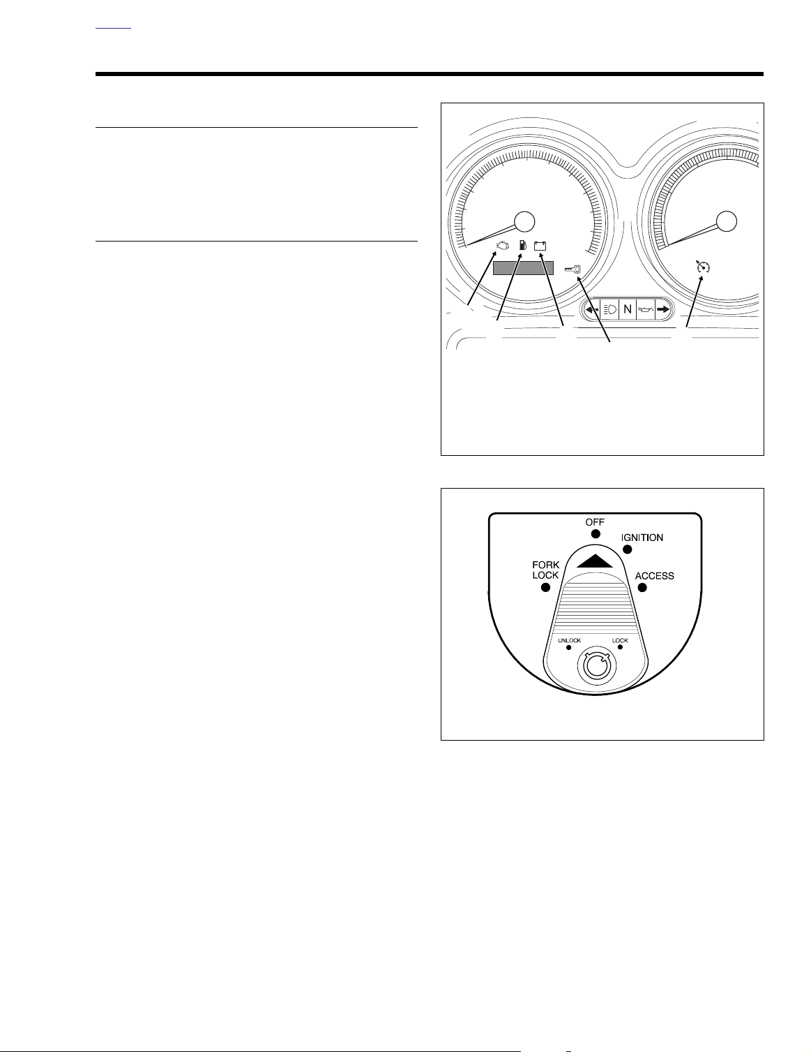
Check Engine Lamp
2
HOME
2004 CHECKING FOR DIAGNOSTIC TROUBLE CODES 2.1
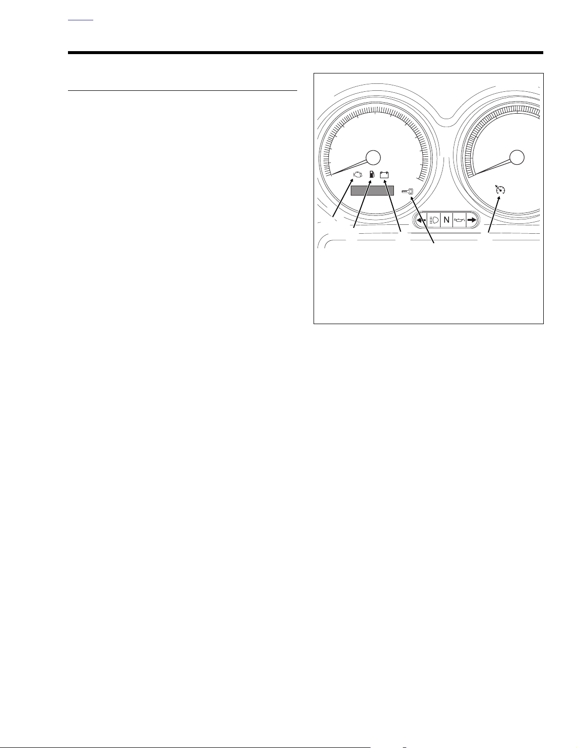
CHECK ENGINE LAMP
To diagnose electronic control module (ECM) or ignition control module (ICM) system problems, start by observing the
behavior of the check engine lamp.
NOTES
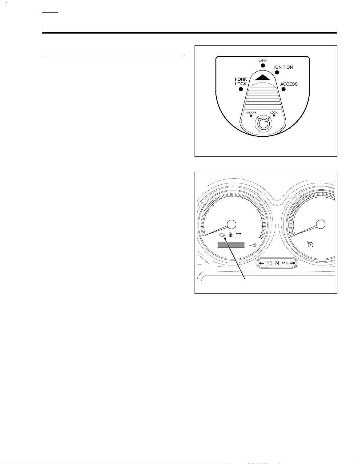
See Figure 2-2. “Key ON” means that the ignition key is
●
turned to ON and the engine stop switch is set to RUN
(although the engine is
When the ignition switch is turned ON, the check engine
●
lamp will illuminate for approximately four seconds and
then turn off.
●
If the check engine lamp is not illuminated at Key ON.
See 2.2 INITIAL DIAGNOSTIC CHECK: SPEEDOME-
TER.
If the check engine lamp comes on late (after 20 sec-
●
onds). See 2.2 INITIAL DIAGNOSTIC CHECK: SPEED-
OMETER.
If the check engine lamp fails to turn OFF after the initial
●
four second period. See 2.2 INITIAL DIAGNOSTIC
CHECK: SPEEDOMETER.
not
running).
Figure 2-2. Ignition Switch (FLTR, FLHT/C/U)
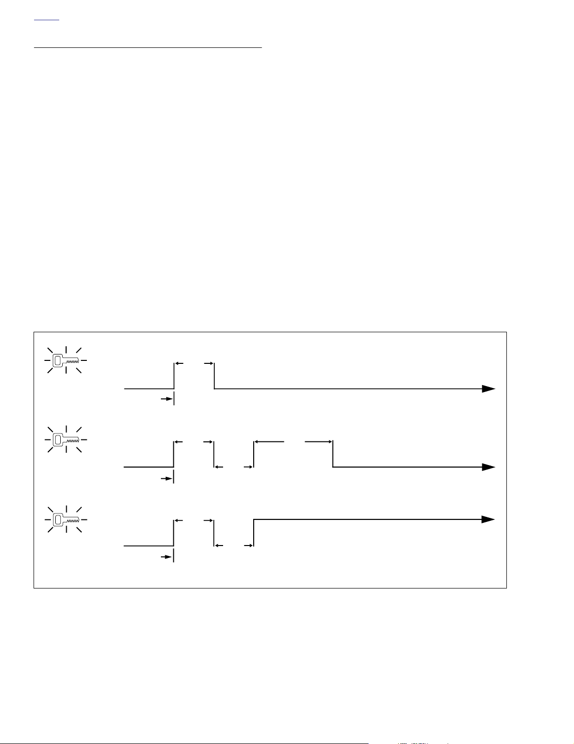
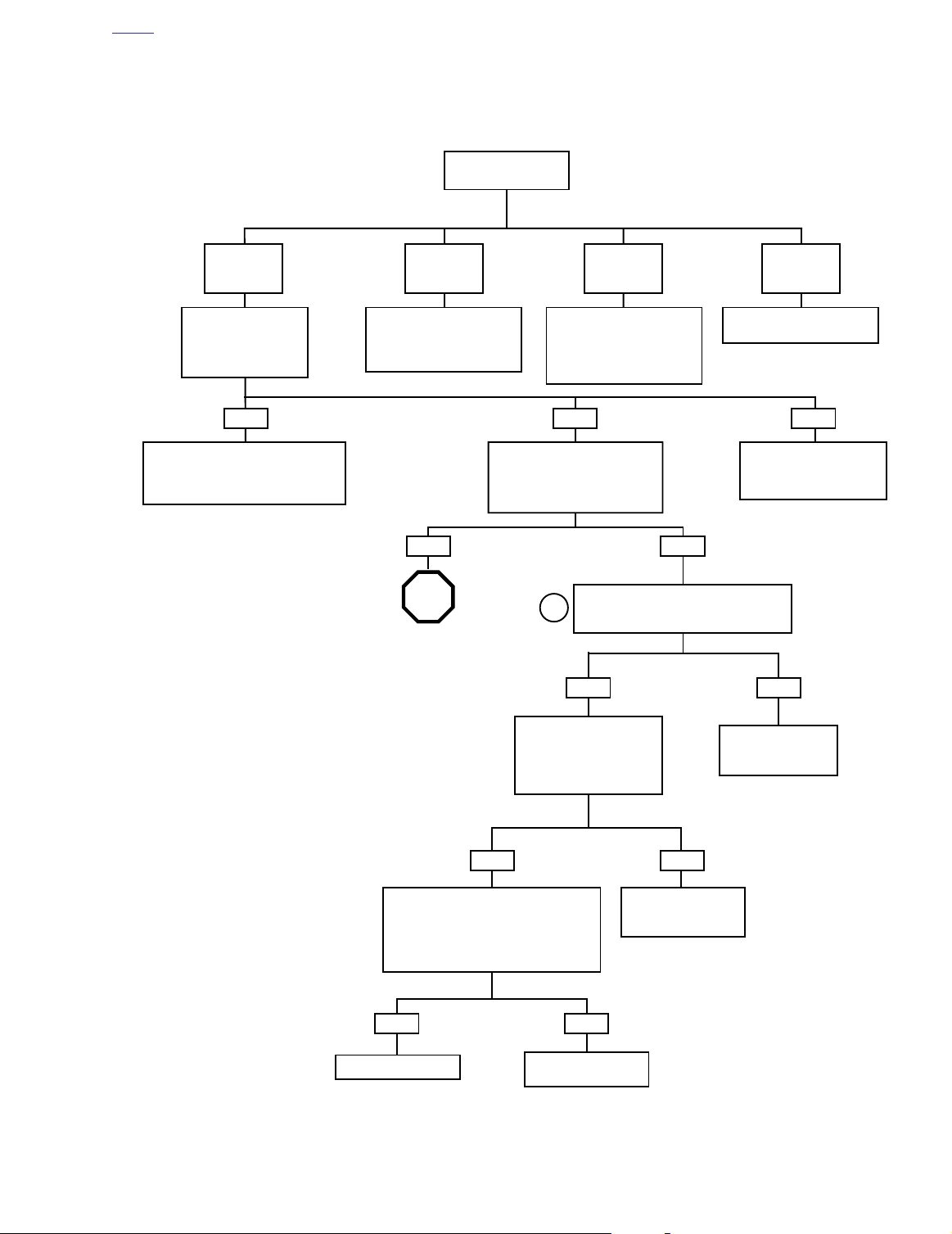
1. See Figure 2-3. After lamp turns off after being illuminated for the first four second period, one of three situations may occur.
a. The lamp remains off. This indicates there are no
current fault conditions or stored diagnostic trouble
codes (DTC) currently detected by the ignition control module (ICM) or electronic control module
(ECM).
b. The lamp stays off for only four seconds and then
comes back on for an eight second period. This indicates an diagnostic trouble code is stored, but no
current diagnostic trouble code exists.
c. If the lamp remains on beyond the eight second
Figure 2-1. Speedometer
period, then a current diagnostic trouble code exists.
2. See CODE TYPES which follows for a complete descrip-
tion of diagnostic trouble code formats.
NOTES
Some diagnostic trouble codes can only be fully diagnosed
during actuation. For example, a problem with the ignition coil
will be considered a current fault even after the problem is
corrected, since the ECM/ICM will not know of its resolution
until after the coil is exercised by vehicle start sequence. In
this manner, there may sometimes be a false indication of the
current diagnostic trouble code.
2004 Touring: Instruments 2-1
Page 2
HOME
SECURITY LAMP
To diagnose TSM/TSSM system problems, start by observing
the behavior of the security lamp.
NOTES
●
To provide an indication of TSM/TSSM diagnostic trouble
codes, the security lamp is enabled on all models.
See Figure 2-2. “Key ON” means that the ignition key is
●
turned to ON and the engine stop switch is set to RUN
(although the engine is
●
When the ignition switch is turned ON, the check engine
lamp will illuminate for approximately four seconds and
then turn off.
If the check engine lamp is not illuminated at Key ON,
●
see 2.2 INITIAL DIAGNOSTIC CHECK: SPEEDOME-
TER.
●
If the check engine lamp comes on late (after 20 seconds), see 2.2 INITIAL DIAGNOSTIC CHECK: SPEED-
OMETER.
If the check engine lamp fails to turn OFF after the initial
●
four second period, see 2.2 INITIAL DIAGNOSTIC
CHECK: SPEEDOMETER.
not
running).
1. See Figure 2-3. After lamp turns off after being illumi-
nated for the first four second period, one of three situations may occur.
a. The lamp remains off. This indicates there are no
current fault conditions or stored diagnostic trouble
codes currently detected by the ignition control module (ICM) or electronic control module (ECM).
b. The lamp stays off for only four seconds and then
comes back on for an eight second period. This indicates an diagnostic trouble code is stored, but no
current diagnostic trouble code exists.
c. If the lamp remains on beyond the eight second
period, then a current diagnostic trouble code exists.
2. See CODE TYPES which follows for a complete description of diagnostic trouble code formats.
NOTE
Some diagnostic trouble codes can only be fully diagnosed
during actuation. For example, a problem with the turn signals
will be considered a current fault even after the problem is
corrected, since the TSM/TSSM will not know of its resolution
until after the turn signals are activated. In this manner, there
may sometimes be a false indication of a diagnostic trouble
code.
ON
OFF
ON
OFF
ON
OFF
A
Key ON
B
Key ON
C
Key ON
4 Sec.
Lamp OFF: No Current or Historic DTCs
Lamp ON 8 Seconds:
Only Historic DTCs Exist
4 Sec.
4 Sec.
4 Sec.
4 Sec.
Figure 2-3. Check Engine and Security Lamp Operation
8 Sec.
Lamp Remains ON: Current DTC *
Historic DTCs May Also Exist
*
Lamp OFF
2-2 2004 Touring: Instruments
Page 3

HOME
CODE TYPES
There are two types of diagnostic trouble codes (DTCs): current and historic. If a diagnostic trouble code is stored, it can
be read using speedometer self diagnostics. See 2.3
SPEEDOMETER SELF DIAGNOSTICS.
All diagnostic trouble codes reside in the memory of the
ECM/ICM, TSM/TSSM, speedometer or tachometer until the
code is cleared by use of the speedometer self diagnostics.
See 2.3 SPEEDOMETER SELF DIAGNOSTICS.
A historic diagnostic trouble code is also cleared after a total
of 50 trips has elapsed. A trip consists of a start and run
cycle. After the 50 trip retention period, the diagnostic trouble
code is automatically erased from memory providing that no
subsequent faults of the same type are detected in that
period.
Current
Current diagnostic trouble codes are those which presently
disrupt motorcycle operation. See the appropriate flow charts
for solutions.
Historic
Historic diagnostic trouble codes can only be identified as historic using a computer based diagnostic package called DIGITAL TECHNICIAN (Part No. HD-44750), when historic
diagnostic codes are present.
If a particular problem happens to resolve itself, the active
status problem is dropped and it becomes a historic fault
rather current fault.
Historic diagnostic trouble codes are stored for a length of
time to assist in the diagnosis of intermittent faults.
It is important to note that historic diagnostic trouble codes
may also be present whenever the system indicates the existence of a current fault. See MULTIPLE DIAGNOSTIC TROU-
BLE CODES if multiple diagnostic trouble codes are found.
RETRIEVING DIAGNOSTIC TROUBLE CODES
The engine management system provides two levels of diagnostics.
●
The most sophisticated mode employs a computer
based diagnostic package called DIGITAL TECHNICIAN
(Part No. HD-44750).
●
The second mode requires using the speedometer self
diagnostics. Speedometer, tachometer (if equipped),
TSM/TSSM and ECM diagnostic trouble codes can be
accessed and cleared. See 2.3 SPEEDOMETER SELF
DIAGNOSTICS.
MULTIPLE DIAGNOSTIC TROUBLE CODES
While it is possible for more than one fault to occur and set
more than one diagnostic trouble code, there are several conditions which may result in
tic trouble codes:
Serial data diagnostic trouble codes (DTC U1016, U1064,
U1097, U1255, U1300 and U1301) may be accompanied by
other codes.
codes before resolving the other codes.
For proper resolution to multiple diagnostic trouble codes
refer to diagnostic trouble code priority chart page 2-6,Ta b le
2-2.
Always
one
fault setting
correct the serial data diagnostic trouble
multiple
diagnos-
Diagnostic charts are designed for use with current diagnostic trouble codes and as a result they frequently suggest wire
repair or part replacement.
2004 Touring: Instruments 2-3
Page 4
HOME
INITIAL DIAGNOSTIC CHECK: SPEEDOMETER 2.2
GENERAL
●
Constant power is supplied to the speedometer through
terminal 5 of connector [39]. The speedometer turns on
when power is applied to terminal 1 of connector [39].
The speedometer goes through an initialization
sequence every time power is removed and re-applied to
terminal 6. The visible part of this sequence is the check
engine lamp (in “run” mode), security lamp (models with
security only), backlighting, odometer and fuel level (EFI
only). Upon key ON, the check engine lamp and security
lamp will illuminate for 4 seconds and then (if parameters
are normal) go out.
●
To locate faulty circuits or other system problems, follow
the diagnostic flow charts and tests in this section. For a
systematic approach, always begin with INITIAL DIAG-
NOSTICS which follows. Read the general information
and then work your way through the flow chart box by
box.
●
Loss of power on any of the four power inputs will
change speedometer behavior. Refer to Ta bl e 2-1.
Speedometer Function Chart-Loss Of Input.
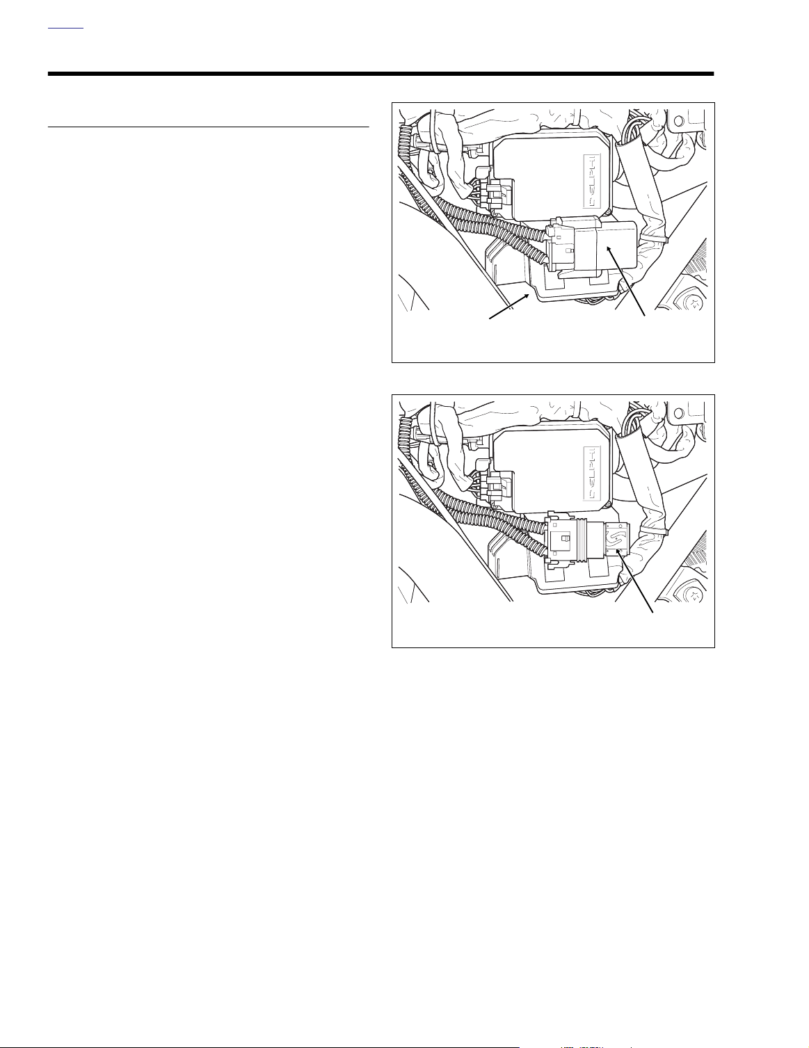
f2206x8x
Fuse
Block
Figure 2-4. Remove Left Side Cover
Maxi-Fuse
Cover
Diagnostic Notes
If a numbered circle appears adjacent to a flow chart box,
then more information is offered in the diagnostic notes. Many
diagnostic notes contain supplemental information, descriptions of various diagnostic tools or references to other parts
of the manual where information on the location and removal
of components may be obtained.
Circuit Diagram/Wire Harness Connector Table
When working through a flow chart, refer to the illustrations,
the associated circuit diagram and the wire harness connector table as necessary. The wire harness connector table for
each circuit diagram identifies the connector number, description, type and general location.
In order to perform most diagnostic routines, a Breakout Box
and a digital volt/ohm meter (DVOM) are required. See 2.5
BREAKOUT BOX: SPEEDOMETER.
To perform the circuit checks with any degree of efficiency, a
familiarity with the various wire connectors is also necessary.
f2207x8x
Maxi-Fuse
Figure 2-5. Remove Maxi-Fuse Cover
2-4 2004 Touring: Instruments
Page 5
HOME
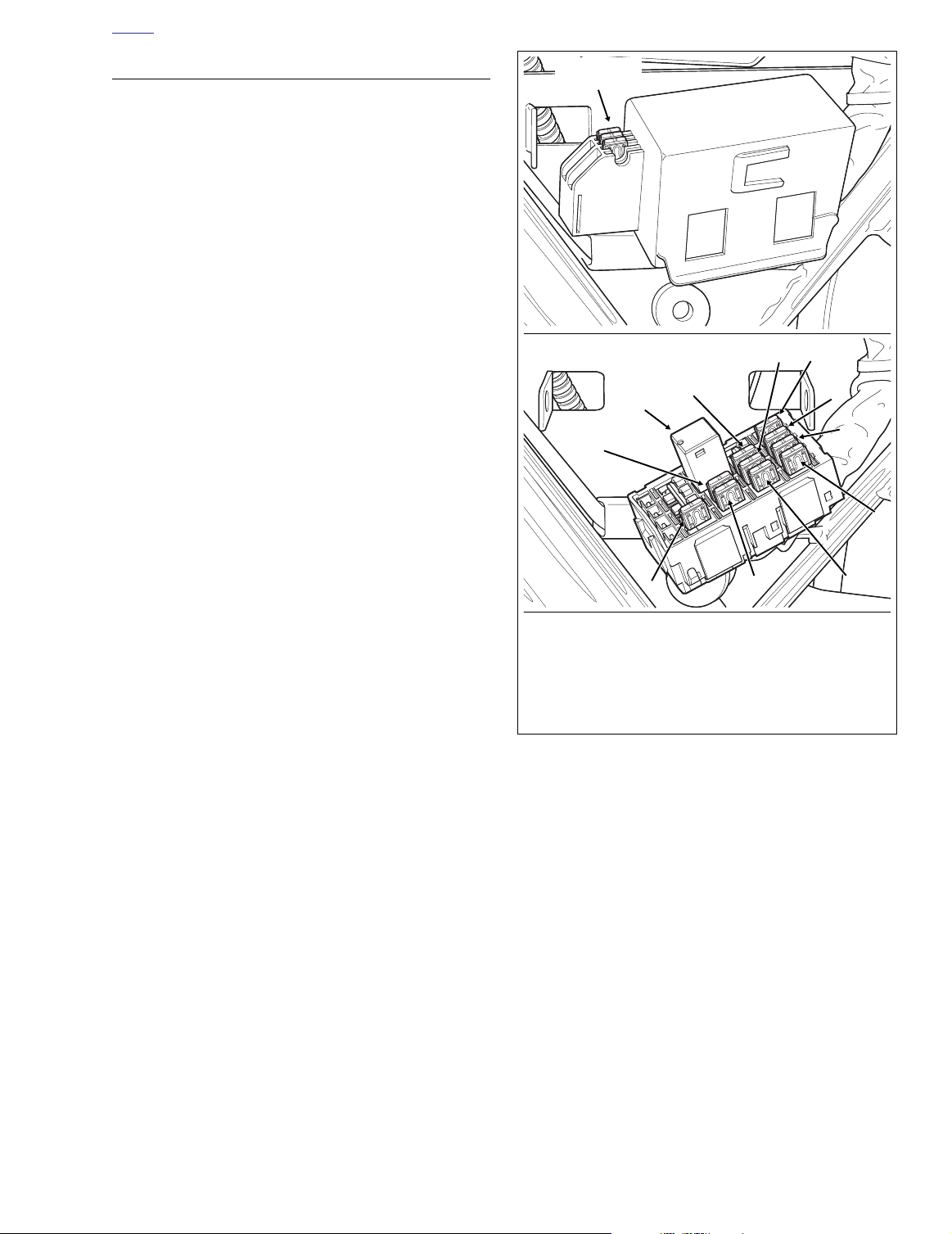
1. Headlamp
2. Ignition
3. Lighting
4. Instruments
5. Brakes/Cruise
6. Radio Memory
7. Radio Power
8. Accessory
9. Battery
10. Brake Light Relay
11. P&A
Fuse Block
Cover
Spare Fuse
Holder
f2209x8x
f2203x8x
11
10
9
1
8
7
6
5
4
3
2
INITIAL DIAGNOSTICS
Diagnostic Tips
If Speedometer reads “BUS Er” with the ignition key
●
turned ON (engine stop switch at RUN with the engine
off), check data bus for an open or short to ground.
between data link connector [91A] terminal 3 and ICM
connector [10B] terminal 12 (carbureted models), ECM
connector [78B] terminal 5 (EFI models), TSSM connector [30B] terminal 3, Speedometer connector [39B] terminal 2 or tachometer (if equipped) connector [108B]
terminal 2.
Check for an open data test terminal between data link
●
connector [91A] terminal 3 and TSM/TSSM connector
[30B] terminal 3. With ignition key turned ON, serial data
bus voltage should be typically 0.6-0.8 volts. The range
of acceptable voltage is greater than 0 and less than 7.0
volts.
To identify intermittents, wiggle instrument and/or vehicle
●
harness while performing steps in the Diagnostic Check
charts.
Diagnostic Notes
The reference numbers below correlate with the circled numbers on the diagnostic check flow charts. See page 2-11.
1. Connect BREAKOUT BOX (Part No. HD-42682) and
INSTRUMENT HARNESS ADAPTERS (Part No. HD-
46601) between wire harness and speedometer.
All Speedometer diagnostic trouble codes are listed on page
2-6 in Ta bl e 2-2.
Other Codes
See 3.9 INITIAL DIAGNOSTIC CHECK: TSM/TSSM for any
diagnostic trouble codes related to the turn signal module
(TSM) or turn signal security module (TSSM).
See 4.4 INITIAL DIAGNOSTIC CHECK: ICM for any diagnos-
tic trouble codes related to the ignition control module (ICM).
See 5.5 INITIAL DIAGNOSTIC CHECK: EFI for any diagnostic trouble codes related to the electronic control module
(ECM).
Figure 2-6. Fuse Block (FLTR, FLHTC/U)
2004 Touring: Instruments 2-5
Page 6
HOME
Table 2-1. Speedometer Function Chart-Loss Of Input
Terminal 5
(Constant)
●
Security lamp
glows dimly during 4-second
bulb check
Terminal 1 (IGN) Terminal 6 (ACC) Terminal 7 (GRD)
●
Will not “wow”
●
Tu rn signals still functional
Speedometer will indicate
●
vehicle speed (zero)
Ta chometer unaffected
●
●
Security lamp still functional
●
Check engine lamp and
●
Speedometer will
be non-functional
in accessory and
ignition modes
Security lamp still
●
performs 4-second bulb check in
ignition mode
●
Speedometer completely non-functional
●
Diagnostics absent
Terminal 8 and 11
(Reset Switch)
●
No reset switch
function
●
Will not “wow”
battery lamp non-functional
●
Diagnostics absent
Table 2-2. Speedometer/Tachometer Diagnostic Trouble Codes (DTC) Priority Chart
DTC
“BUS Er” 1 Serial data bus shorted low/open/high
U1300 2 Serial data bus shorted low
U1301 3 Serial data bus shorted open/high
U1016 4 Loss of ECM serial data 2.13 DTC U1016 Speedometer/tachometer
U1064 5 Loss of TSM/TSSM serial data 2.14 DTC U1064, U1255 Speedometer/tachometer
U1255 6
B1007 7 Ignition line overvoltage 2.11 DTC B1006, B1007 Speedometer/tachometer
B1006 8 Accessory line overvoltage 2.11 DTC B1006, B1007 Speedometer/tachometer
B1008 9 Reset switch closed 2.12 DTC B1008 Speedometer
B1004 10 Fuel level sending unit low 2.10 DTC B1004, B1005 Speedometer
B1005 11 Fuel level sending unit high/open 2.10 DTC B1004, B1005 Speedometer
PRIORITY FAULT CONDITION SOLUTION MODULE
Missing response from other module
(TSM/TSSM and/or ICM/ECM) at startup
2.15 DTC U1300, U1301
or “BUS ER”
2.15 DTC U1300, U1301
or “BUS ER”
2.15 DTC U1300, U1301
or “BUS ER”
2.14 DTC U1064, U1255 Speedometer/tachometer
Speedometer/tachometer
Speedometer/tachometer
Speedometer/tachometer
2-6 2004 Touring: Instruments
Page 7
HOME
Ignition Control Module
Data Link
TSM/TSSM
LtGN/V
15A
Ignition
Fuse
GY
[8B]
[8A]
[91A]
LtGN/V
BK
LtGN/V
[39B]
[39A]
[10B]
[10A]
Speedometer
O
BK
Serial data
[108B]
[108A]
Tachometer
BN/GY
[156B] [156A]
[30B]
[30A]
15A
Accessory
Fuse
[1B] [1A]
Main to Interconnect
Harness
Ignition
Harness
Main to Interconnect
Harness
f2208z8x
15A
Battery
Fuse
[2A]
[2B]
Main to Interconnect
Harness
BK
GY
BN/GY
321654987121110
321654987121110
321654987121110
321654987121110
6
6
5
5
4
4
3
3
2
2
1
1
321654987121110
321654987121110
121110
987
65
4
32
1
1
6
5
4
32
121110
987
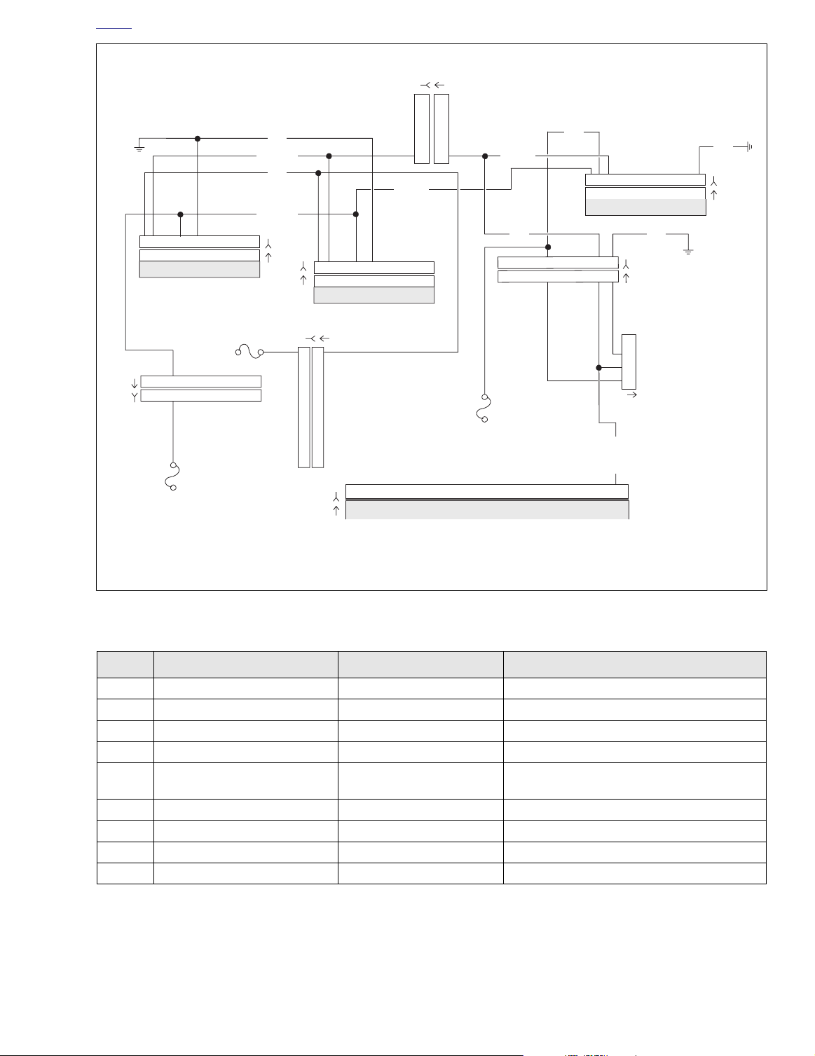
NO. DESCRIPTION TYPE LOCATION
[1] Main to Interconnect Harness 12-Place Deutsch (Black) Inner Fairing - Right Radio Support Bracket
[2] Main to Interconnect Harness 12-Place Deutsch (Gray) Inner Fairing - Right Fairing Support Brace
[8] Ignition Harness 12-Place Deutsch Under Right Side Cover
[10] Ignition Control Module 12-Place Deutsch Under Right Side Cover
[30] Turn Signal/Security Module 12-Place Deutsch
[39] Speedometer 12-Place Packard Inner Fairing (Back of Speedometer)
[91] Data Link 4-Place Deutsch Under Right Side Cover
[108] Tachometer 12-Place Packard Inner Fairing (Back of Tachometer)
[156] Main to Interconnect Harness 6-Place Deutsch Inner Fairing - Right Fairing Support Brace
321654987121110
321654987121110
123
123
6
6
101112 78945
101112 78945
Figure 2-7. Diagnostic Check: FLHT/C (Carbureted)
Table 2-3. Wire Harness Connectors in Figure 2-7.
Cavity in Crossmember at Rear of Battery Box
1
2
3
4
12
12
(Under Seat)
2004 Touring: Instruments 2-7
Page 8
HOME
f2208y8x
BN/GY
BK
321654987121110
321654987121110
15A
Battery
Fuse
Speedometer
LtGN/V
BN/GY
O
15A
Accessory
Fuse
[39B]
[39A]
15A
Ignition
Fuse
LtGN/V
GY
21
21
GY
BK
321654987121110
321654987121110
[30B]
[30A]
TSM/TSSM
BK
[8B]
[8A]
[91A]
Ignition
Harness
1
2
3
4
Data Link
987
6
54
3
98
7
654
3
121110
121110
LtGN/V
[10B]
[10A]
Ignition Control Module
12
12
Serial data
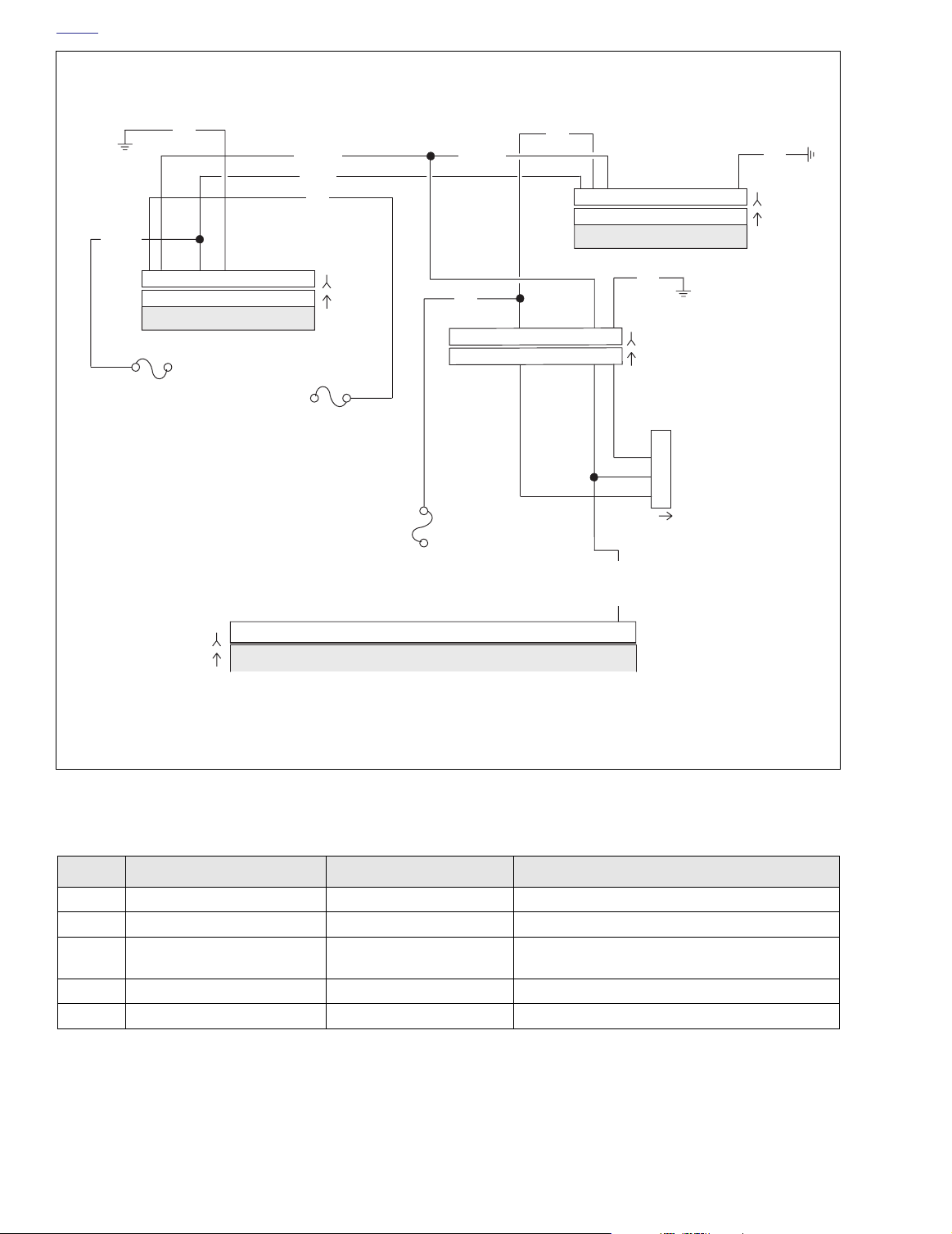
Figure 2-8. Diagnostic Check: FLHR/S (Carbureted)
Table 2-4. Wire Harness Connectors in Figure 2-8.
NO.
[8] Ignition Harness 12-Place Deutsch Under Right Side Cover
[10] Ignition Control Module 12-Place Deutsch Under Right Side Cover
[30] Turn Signal/Security Module 12-Place Deutsch
[39] Speedometer 12-Place Packard Under Console (Back of Speedometer)
[91] Data Link 4-Place Deutsch Under Right Side Cover
DESCRIPTION TYPE LOCATION
Cavity in Crossmember at Rear of
Battery Box (Under Seat)
2-8 2004 Touring: Instruments
Page 9

HOME
ECM
Data Link
TSM/TSSM
LtGN/V
15A
Ignition
Fuse
GY
[8B]
[8A]
[91A]
LtGN/V
BK
LtGN/V
[39B]
[39A]
[78B]
[78A]
Speedometer
O
BK
Serial data
[108B]
[108A]
Tachometer
BN/GY
[156B] [156A]
[30B]
[30A]
15A
Accessory
Fuse
[1B] [1A]
Main to Interconnect
Harness
Ignition
Harness
Main to Interconnect
Harness
f2208u8x
15A
Battery
Fuse
[2B]
[2A]
Main to Interconnect
Harness
LtGN/R
BK
BN/GY
GY
Flash pin
321654987121110
321654987121110
321654987121110
321654987121110
6
6
5
5
4
4
3
3
2
2
1
1
321654987121110
321654987121110
121110
987
65
4
32
1
1
65
4
32
121110
987
NO.
[1]
[2]
[8] Ignition Harness All 12-Place Deutsch Under Right Side Cover
[10] Ignition Control Module All 12-Place Deutsch Under Right Side Cover
[30]
[39] Speedometer
[91] Data Link All 4-Place Deutsch Under Right Side Cover
[108] Tachometer
[156]
123
123
321654987121110
321654987121110
6
6
101112 78945
101112 78945
51
DESCRIPTION MODEL TYPE LOCATION
Main to Interconnect
Harness
Main to Interconnect
Harness
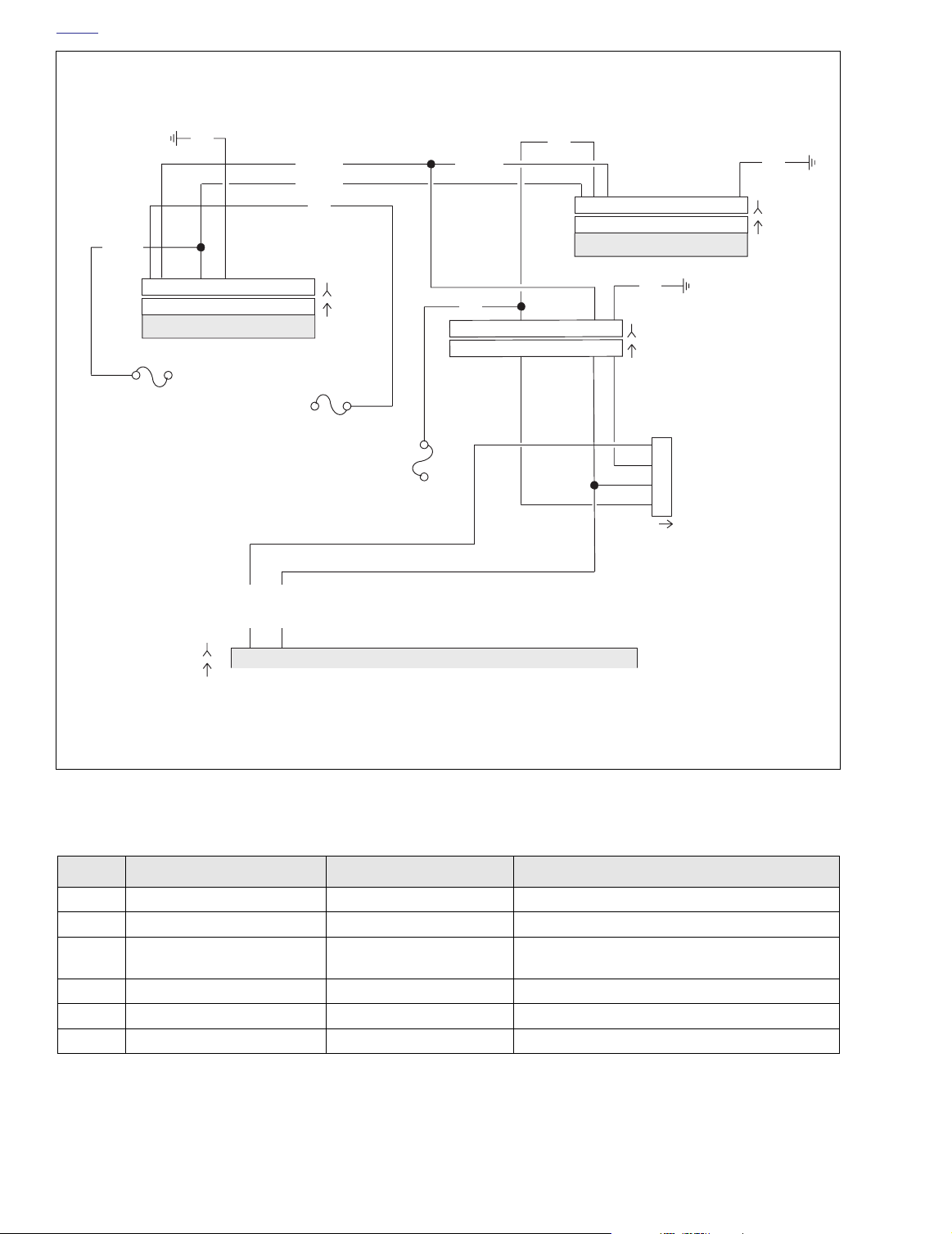
Figure 2-9. Diagnostic Check: FLTR, FLHT/C/U (Fuel Injected)
Table 2-5. Wire Harness Connectors in Figure 2-9.
FLHT/C 12-Place Deutsch (Black) Inner Fairing - Right Radio Support Bracket
FLTR 12-Place Deutsch (Black) Inner Fairing - Below Radio (Left Side)
FLHT/C 12-Place Deutsch (Gray) Inner Fairing - Right Fairing Support Brace
FLTR 12-Place Deutsch (Gray) Inner Fairing - Below Radio (Left Side)
Tu rn Signal/Security
Module
All 12-Place Deutsch
FLHT/C 12-Place Packard Inner Fairing (Back of Speedometer)
FLTR 12-Place Packard Under Bezel (Back of Speedometer)
Cavity in Crossmember at Rear of
Battery Box (Under Seat)
FLHT/C 12-Place Packard Inner Fairing (Back of Tachometer)
FLTR 12-Place Packard Under Bezel (Back of Tachometer)
Main to Interconnect
Harness
FLHT/C 6-Place Deutsch Inner Fairing - Right Fairing Support Brace
FLTR 6-Place Deutsch Inner Fairing - Front of Right Fairing Bracket
2004 Touring: Instruments 2-9
1
2
3
4
Page 10
HOME
f2208t8x
BN/GY
321654987121110
321654987121110
Speedometer
15A
Battery
Fuse
BK
15A
Accessory
Fuse
LtGN/V
BN/GY
O
[39B]
[39A]
15A
Ignition
Fuse
LtGN/V
GY
3
21
321
GY
BK
321654987121110
321654987121110
[30B]
[30A]
TSM/TSSM
BK
98
7
65
4
98
7
65
4
121110
[8B]
Ignition
[8A]
Harness
121110
1
2
3
4
Data Link
[91A]
LtGN/V
LtGN/R
[78B]
[78A]
1
Flash pin
5
Serial data
ECM
Figure 2-10. Diagnostic Check: FLHR/C/S (Fuel Injected)
Table 2-6. Wire Harness Connectors in Figure 2-10.
NO.
[8] Ignition Harness 12-Place Deutsch Under Right Side Cover
[10] Ignition Control Module 12-Place Deutsch Under Right Side Cover
[30] Turn Signal/Security Module 12-Place Deutsch
[39] Speedometer 12-Place Mini-Deutsch Under Console (Back of Speedometer)
[78] Electronic Control Module 36-Place Packard Under Right Side Cover
[91] Data Link 4-Place Deutsch Under Right Side Cover
DESCRIPTION TYPE LOCATION
Cavity in Crossmember at Rear of
Battery Box (Under Seat)
2-10 2004 Touring: Instruments
Page 11
HOME
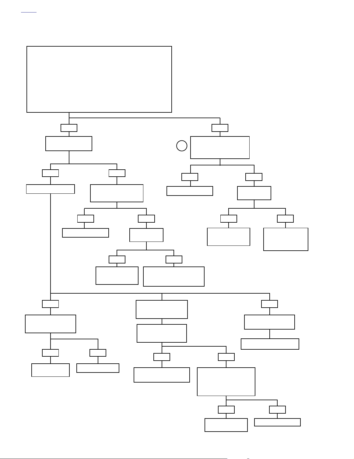
Diagnostic Check (Part 1 of 2)
Does engine
start?
YES.
Starts and
runs.
Check for diagnostic
trouble codes. See 2.3
SPEEDOMETER SELF
DIAGNOSTICS
Codes found?
YES
Refer to applicable diagnostic trouble
code priority chart. All diagnostic codes
are listed on page 2-6 in Table 2-2.
Codes are listed by priority.
YES.
Starts, then
stalls.
For carbureted models, see
4.10 STARTS, THEN STALLS.
For EFI models, see 5.12
STARTS, THEN STALLS.
Unable to enter diagnostic mode.
With ignition switch OFF, press and
release odometer reset switch.
Does odometer display appear with
YES
STOP
Go to Diagnostic
Check (Part 2 of 2).
NO.
Cranks, but
will not start.
For carbureted models, see 4.9
ENGINE CRANKS, BUT WILL
NOT START. For EFI models,
see 5.10 ENGINE CRANKS,
BUT WILL NOT START.
NO
display backlighting?
Check for continuity to ground on terminal 7
of speedometer. Wiggle harness during con-
1
Check for battery voltage at
terminal 5 of speedometer
while wiggling harness. Bat-
tery voltage continuously
tinuity check. Continuity present?
YES NO
present?
NO
Locate and repair open
NO.
Engine will not
crank.
See 1.2 STARTING SYSTEM
DIAGNOSIS.
NO
No codes displayed. For
symptoms that may not set
diagnostic trouble codes,
refer to Table 2-1.
between terminal 7
and ground.
YES NO
With connector [39] disconnected from
speedometer, check continuity (with ignition
switch OFF) between terminals 8 and 11 on
Breakout Box. Continuity present when
speedometer reset switch is depressed and
Replace speedometer.
infinity when released?
Locate and repair open
between terminal 5 and
NOYES
Replace speedometer
reset switch.
battery fuse.
2004 Touring: Instruments 2-11
Page 12
HOME
Diagnostic Check (Part 2 of 2)
Perform “wow” test. See 2.3 SPEEDOMETER SELF DIAGNOSTICS.
1) backlight should illuminate
2) needle should sweep its full range of motion
3) LED’s that should illuminate:
• check engine
• battery
• security (all models)
4) LED’s that may illuminate:
• low fuel (EFI models)
• cruise (although not cruise equipped on some models)
Is problem intermittent?
Continued from Diagnostic Check (Part 1 of 2).
The following features should be functional
Are all features functional?
YES
Turn key to ACC. Is
backlight present?
YES
Check for battery voltage at
breakout box terminal 6.
Battery voltage present?
YES
NO
NO
NO
With ignition switch turned to
IGN, check for battery voltage
1
at terminal 1 of Breakout Box.
Battery voltage present?
YES NO
Replace Speedometer.
Is instrument
fuse blown?
YES NO
Replace speedometer.
YES
Repeat Diagnostic Check
while wiggling harnesses.
Intermittent present?
YES NO
Locate and repair
intermittent.
Locate and repair
source of fault.
Replace fuse.
No trouble found.
YES
Is accessory fuse
blown?
Locate and repair open on O/W
wire between termin al 6 of con-
nector [39] and accessory fuse.
Intermittent vehicle speed
Remove and inspect vehi-
YES
indication.
cle speed sensor. Debris
present?
YES
Remove debris. Reinstall
vehicle speed sensor.
NO
Locate and repair
source of fault.
Replace fuse.
Tachometer Inoperative
See Test 2.4 (Part 1 of 2).
NO
Check for damaged wiring/
loose connection between
vehicle speed sensor and ICM/
ECM. Is wiring damage/loose
connection present?
Locate and repair open
between terminal 1 of
connector [39] and
instrument fuse.
NO
(no engine speed).
2-12 2004 Touring: Instruments
YES NO
source of fault.
Replace Speedometer.Locate and repair
Page 13
HOME
0
10
30
20
50
40
110
120
60
70
80
90
100
0
20
30
40
50
10
MPH
H
A
R
L
E
Y
-
D
A
V
I
D
S
O
N
C
E
R
T
I
F
I
E
D
RPM
x100
H
A
R
L
E
Y
-
D
A
V
I
D
S
O
N
f2160x8x
1. Check Engine
2. Low Fuel
3. Battery
4. Security
5. Cruise (Where Applicable)
1
2
3
4
5
f1240x2x
SPEEDOMETER SELF DIAGNOSTICS 2.3
GENERAL
The speedometer is capable of displaying and clearing
speedometer, tachometer, TSM/TSSM, and ICM/ECM diagnostic trouble codes (diagnostic mode).
DIAGNOSTICS
Diagnostic Tips
● For a quick check of speedometer function, a “wow” test
can be performed. Press and hold odometer reset switch
then turn ignition switch ON. Release reset switch. Background lighting should illuminate, speedometer needle
should sweep its full range of motion, and indicator
lamps [battery, security, low fuel (EFI models) check
engine and cruise should illuminate. Some lamps may
illuminate even though they do not apply to the vehicle.
For example, the cruise lamp may illuminate although
this feature does not apply to some models.
● If instrument module fails “wow” test, check for battery,
ground, ignition, speedometer reset switch and accessory to speedometer. If any feature in the speedometer is
non-functional, see 2.2 INITIAL DIAGNOSTIC CHECK:
SPEEDOMETER.
Diagnostic Notes
Use of speedometer self diagnostics assumes that DIGITAL
TECHNICIAN (Part No. HD-44750) is not available.
The reference numbers below correlate with the circled numbers in the Speedometer Self Diagnostics (chart)
1. To exit diagnostic mode, turn ignition switch OFF.
2. To clear diagnostic trouble codes (DTCs) for selected
module, press speedometer reset switch for more than 5
seconds when code is displayed. This procedure will
clear all diagnostic trouble codes for selected module.
Figure 2-11. Icons
Figure 2-12. Ignition Switch (FLTR, FLHT/C/U)
2004 Touring: Instruments 2-13
Page 14
HOME
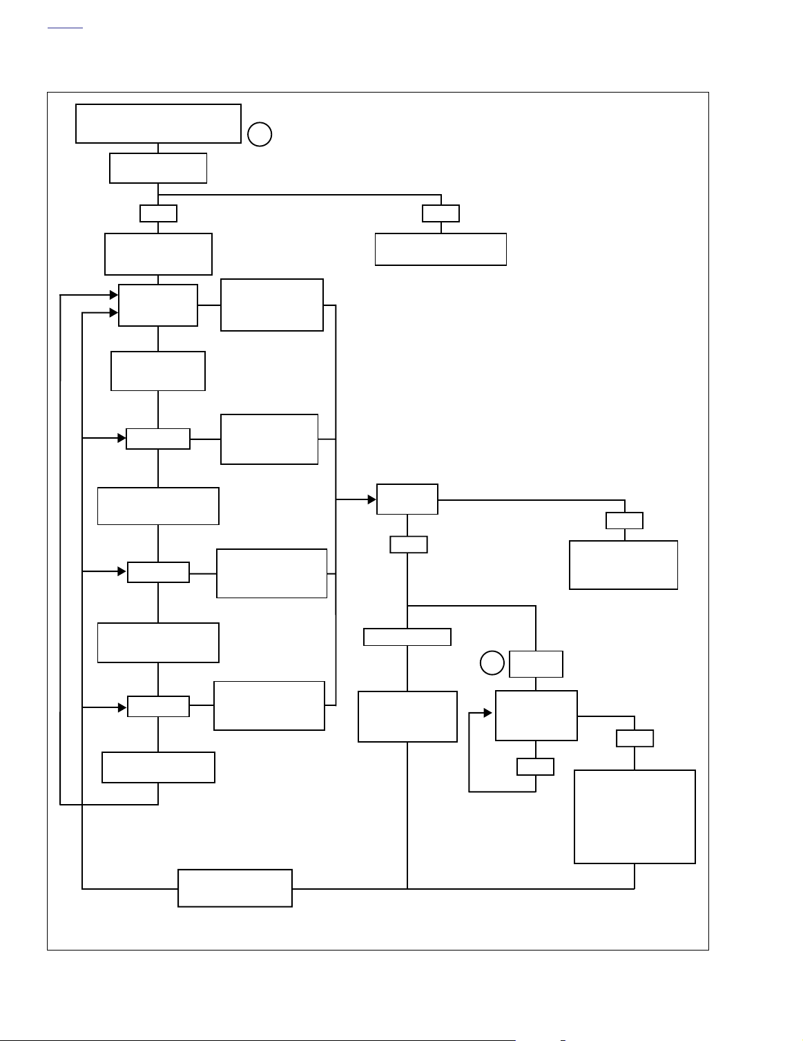
Speedometer Self Diagnostics (chart)
While holding odometer reset switch in,
turn ignition switch to IGN. Make sure
Run/Stop switch is in RUN position.
Release reset switch.
Does “diag” appear?
YES NO
1
Press and release reset
switch.
“PSSPT” appears.
”P” flashing.
To choose TSM/
TSSM, press and
release reset switch.
”S” flashing.
To choose Speedometer,
press and release reset
switch.
”SP” flashing.
To choose Tachometer,
press and release reset
switch.
”T” flashing.
To choose ICM, press and
release reset switch.
To display DTCs for the
ECM/ICM, press and
hold reset switch for
more than 5 seconds.
To display DTCs for
TSM/TSSM, press and
hold reset switch for
more than 5 seconds.
To display DTCs for
speedometer, press and
hold reset switch for more
than 5 seconds.
To display DTCs for
tachometer, press and
hold reset switch for more
than 5 seconds.
See 2.2 INITIAL DIAGNOSTIC
CHECK: SPEEDOMETER.
Device
response?
YES
“none” displayed.
Press and release
reset switch. Part num-
ber of module will be
displayed.
DTC
2
displayed.
Press and release
reset switch.
Are more DTCs
displayed?
YES
NO
“no rsp” displayed.*
Tachometer malfunction.
2.4 SPEEDOMETER/
See
TACHOMETER.
* Models not equipped
with a tachometer will
display “no rsp” normally.
NO
“end” displayed.
To clear all DTCs for
selected module hold reset
switch for more than 5 seconds. If DTCs are not to be
cleared, Press and release
reset switch. Part number of
module will be displayed.
Press and release reset
switch again to continue to
next module.
2-14 2004 Touring: Instruments
Figure 2-13. Speedometer Self Diagnostics
Page 15
HOME
0
10
30
20
50
40
110
120
60
70
80
90
100
0
20
30
40
50
10
MPH
H
A
R
L
E
Y
-
D
A
V
I
D
S
O
N
C
E
R
T
I
F
I
E
D
RPM
x100
H
A
R
L
E
Y
-
D
A
V
I
D
S
O
N
f2160x8x
1. Check Engine
2. Low Fuel
3. Battery
4. Security
5. Cruise (Where Applicable)
1
2
3
4
5
SPEEDOMETER/TACHOMETER 2.4
GENERAL
NOTE
Some icons may illuminate during “wow” test though the icon
has no functionality on that vehicle.
The speedometer consists of a speedometer display and several icons. The icons include: check engine, security, battery,
and low fuel (EFI only).
Reset Switch
See Figure 2-14. Pressing the odometer reset switch pro-
vides the following capabilities:
● Change the odometer display between mileage, trip A
and trip B values (press and immediately release).
● Reset an individual trip odometer (press and hold 2-3
seconds).
● Gain access to the diagnostic mode, clear diagnostic
trouble codes and exit diagnostic mode. See 2.3
SPEEDOMETER SELF DIAGNOSTICS.
● Display odometer while key is OFF. Press and hold reset
switch while key is OFF and odometer mileage will be
displayed.
● On models with dual scale speedometers, toggle
between miles/kilometers on odometer and trip odometer display. To toggle display, turn key ON. Press and
hold reset switch while odometer is displayed. Release
switch when change is noted. (If reset switch is held
while trip odometer is displayed, trip odometer will reset.)
Figure 2-14. Icons (FLHT/C/U)
2004 Touring: Instruments 2-15
Page 16

HOME
SPEEDOMETER THEORY OF OPERATION
The speedometer consists of a vehicle speed sensor, ICM/
ECM, odometer reset switch and the speedometer. The vehicle speed sensor is mounted on the right side of transmission
case below the starter. The sensor circuitry is that of a HallEffect sensor that is triggered by the gear teeth of 4th gear on
the transmission mainshaft.
The output from the sensor is a series of pulses that are interpreted by ICM/ECM circuitry, converted into serial data inside
the ICM/ECM then sent to the speedometer to control the
position of the speedometer needle and the liquid crystal
(LCD) odometer display. The vehicle speed serial data is also
transmitted to the TSM/TSSM for turn signal cancellation.
The odometer mileage is permanently stored and will not be
lost when electrical power is turned off or disconnected. The
odometer reset switch allows switching between the odometer, trip odometer A and trip odometer B displays.
To zero the trip odometer, have the desired trip odometer display visible, press and keep the reset switch depressed. The
trip odometer mileage will be displayed for 2-3 seconds and
then the trip mileage will return to zero miles.
TACHOMETER THEORY OF OPERATION
The tachometer receives serial data from the ICM/ECM. The
tachometer interprets the serial data and converts it into
tachometer needle movement.
DIAGNOSTICS
Diagnostic Notes
The reference numbers below correlate with circled numbers
on the tachometer diagnostic flow chart.
1. If problems are intermittent, wiggle harness while performing tests.
2. Connect BREAKOUT BOX (Part No. HD-42682) and
INSTRUMENT HARNESS ADAPTERS (Part No. HD-
46601) between wire harness and tachometer.
3. Use HARNESS CONNECTOR TEST KIT (Part No. HD-
41404), black pin probe and patch cord.
The odometer can display six numbers to indicate a maximum of 999999 miles/kilometers. The trip odometers can display six numbers with a tenth of a mile accuracy for a
maximum of 99999.9 miles/kilometers.
Job/Time Code Values
Dealership technicians filing warranty claims should use the
job/time code values in Digital Technician.
2-16 2004 Touring: Instruments
Page 17

HOME
Test 2.4 (Part 1 of 2)
TACHOMETER INOPERATIVE
Perform “wow” test. See 2.3 SPEEDOMETER SELF
The following features should be functional
1) backlight should illuminate
2) needle should sweep its full range of motion
3) LED’s may illuminate:
cruise (although not cruise equipped on some
models)
pursuit (although may not be a police vehicle)
DIAGNOSTICS.
Are all features functional?
YES
Is problem intermittent?
YES
Repeat Diagnostic
Check while wiggling
harnesses.
NO
No trouble found.
NO
Check for battery voltage at terminal 1
of breakout box. Is battery voltage
present?
Is instrument
YES NO
NO
fuse blown?
Check for continuity between
breakout box terminal 2 and
terminal 7 of connector [20].
YES
STOP
Go to Test 2.4 (Part
2 of 2).
YES
Is continuity present?
Locate and repair open
Locate and repair
NO
on LGN/V wire.
source of fault.
Replace fuse.
Locate and repair
open in orange wire
between terminal 1 of
connector [108] and
instrument fuse.
2004 Touring: Instruments 2-17
Page 18

HOME
Test 2.4 (Part 2 of 2)
TACHOMETER INOPERATIVE
Continued from Test 2.4 (Part 1 of 2).
Check for continuity to ground on breakout box
terminal 7. Wiggle harness during continuity
check. Is continuity present?
Check for battery voltage at
Is battery voltage present?
YES
Replace tachometer.
Check for battery voltage
at breakout box terminal 5
while wiggling harness.
continuously present?
YES
breakout box terminal 6.
Locate and repair open on O/W
wire between terminal 6 of con-
nector [108] and accessory fuse.
YES
Is battery voltage
NO
NO
Locate and repair open
on BN/GY wire between
terminal 5 of connector
[108] and battery fuse.
NO
Locate and repair open
on BK wire between ter-
minal 7 of connector
[108] and ground.
2-18 2004 Touring: Instruments
Page 19

HOME
10086
f2001x8x
f1998x9x
BREAKOUT BOX: SPEEDOMETER 2.5
GENERAL
The BREAKOUT BOX (Part No. HD-42682) and INSTRUMENT HARNESS ADAPTERS (Part No. HD-46601) connect
to speedometer connector [39]. Used in conjunction with a
DVOM, it allows circuit diagnosis of wiring harness and connections without having to probe with sharp objects
NOTE
See wiring diagrams for speedometer terminal functions.
INSTALLATION
1. See Figure 2-16. Bend back the external latches slightly
and remove connector [39B].
2. Connect Instrument Harness Adapters to connectors
[39A] and [39B].
3. Attach connectors from Breakout Box to Instrument Harness Adapters.
Figure 2-16. Speedometer Connector [39]
REMOVAL
1. Detach connectors from Breakout Box to Instrument Harness Adapters.
2. See Figure 2-15. Detach Instrument Harness Adapters
from connectors [39A] and [39B].
3. Install connector [39B] to speedometer.
Figure 2-17. Breakout Box (Part No. HD-42682)
Figure 2-15. Instrument Harness Adapters
(Part No. HD-46601)
2004 Touring: Instruments 2-19
Page 20

HOME
SPEEDOMETER PERFORMANCE CHECK 2.6
GENERAL
See Figure 2-18. Use the SPEEDOMETER TESTER (Part
No. HD-41354) for speedometer diagnostics. These diagnostics may include:
● Checking speedometer operation.
● Te sting speedometer needle sweeping action.
The tester generates a simulated vehicle speed sensor signal
which is sent to the ICM/ECM. The ICM/ECM interprets the
signal then sends a message to the speedometer. This signal
aids in determining whether speedometer replacement is
necessary.
● Verifies serial data message to speedometer.
NOTES
● Use the following procedures in conjunction with the
manual supplied with the speedometer tester.
● Te st results may be inaccurate if tester battery is low.
TESTING
NOTE
The SPEEDOMETER TESTER (Part No. HD-41354) cannot
be used to verify the calibration of a speedometer and it will
not verify the speedometer’s function to support legal proceedings. It’s purpose is to verify speedometer function when
performing service diagnosis or repair. It can also assist in
determining if speedometer replacement is necessary.
hd41354
Figure 2-18. Speedometer Tester (HD-41354)
Speedometer Operation Test
1. See Figure 2-19. Disconnect the 3-place vehicle speed
sensor connector [65] under right side cover (behind
electrical bracket). Attach speedometer tester connector.
2. Place speedometer tester power switch in the ON position. Place signal switch in the OUT position.
3. Turn vehicle ignition switch ON and Run/Off switch to
Run.
4. When speedometer tester displays “P_ _ _ _1”:
a. Press 1 and ENTER on the tester keypad.
b. Enter a frequency from Ta ble 2-7. Note that different
markets use different frequencies.
c. Verify that speedometer display reads the corre-
sponding speed. To change the test frequency,
press CLEAR to cancel and enter the new frequency. Press ENTER to begin and reverify.
NOTE
The speedometer should be accurate within -0 to +4 MPH (0
to +6.5 KPH).
Table 2-7. Speedometer Test Frequency in Hertz (All Models Except Police)
MARKET 20 MPH 40 MPH 60 MPH 80 MPH 30 KPH 60 KPH 100 KPH 130 KPH
DOMESTIC 442 885 1327 1770 - - - -
CANADA ----41382513751788
HDI ----41382513751788
GREAT BRITAIN 442 885 1327 1770 413 825 1375 1788
JAPAN ----44889614931941
Table 2-8. Speedometer Test Frequency in Hertz (Police)
MARKET 20 MPH 40 MPH 60 MPH 80 MPH 30 KPH 60 KPH 100 KPH 130 KPH
DOMESTIC 462 924 1386 1848 ----
CANADA ----43186114351866
HDI ----43186114351866
GREAT BRITAIN 462 924 1386 1848 431 861 1435 1866
JAPAN ----43186114351866
2-20 2004 Touring: Instruments
Page 21

HOME
Deutsch Socket
Housings
Deutsch Pin
Housing
f1437a8x
Tester Connector
Speedometer Sensor
Connector [65]
5087
See Figure 2-20. Fabricate a test harness using the following
parts. This harness can also be used to test the tachometer.
● Tw o Deutsch 3-place socket housings (Part No. 72113-
94BK) and six socket terminals (Part No. 72191-94).
● Deutsch 3-place pin housing (Part No. 72103-94BK) and
three pin terminals (Part No. 72190-94).
● Six lengths of 18 gauge wire, each 6.0 in. (15 cm) long.
Before attempting the actual vehicle speed sensor check, two
system checks must be made. Install the test harness at the
speedometer sensor connector.
● Te st for voltage to sensor by checking for 8-12 volts on
red wire in connector [65B].
● Then check for continuity to ground on black wire in con-
nector [65B].
Figure 2-19. Mate Sensor and Tester Connectors
Speedometer Needle Sweep Test
The tester’s sweep function moves the speedometer needle
through the full range of movement. This allows for testing the
smoothness of operation and checking for hesitancy or a
stuck needle.
1. See Figure 2-19. Disconnect vehicle speed sensor connector. Attach speedometer tester connector to speedometer sensor connector.
2. Place speedometer tester power switch in the ON position. Place signal switch in the OUT position.
3. Turn vehicle ignition switch ON.
4. Begin test by pressing 0 on the tester keypad and then
pressing ENTER. The tester will scan for two seconds,
then the tester will put out a 1 Hz signal.
5. Select a test range.
a. Press 2 to select LO range (1-20 Hz).
b. Press 5 to select CEN range (21-999 Hz).
c. Press 8 to select HI range (1000-20,000 Hz).
6. After selecting a range, use the corresponding arrow
keys to accelerate through the range. As you move
through the speed range, check for smooth needle
movement.
a. If testing LO range, press 1 or 3.
b. If testing CEN range, press 4 or 6.
c. If testing HI range, press 7 or 9.
1. Raise rear wheel off floor.
2. Install the test harness between the vehicle speed sensor connectors.
3. Place speedometer tester power switch in the ON position. Place signal switch in the IN position.
4. Plug the speedometer tester into the test harness. Turn
vehicle ignition switch ON.
5. Press ENTER on the tester keypad.
6. Rapidly rotate rear wheel of motorcycle.
a. If reading on speedometer tester changes as wheel
is rotated, speedometer sensor is OK.
b. If reading does not change on carbureted models,
see 4.18 DTC P0501, P0502. If reading does not
change on EFI models, see 5.25 DTC P0501,
P0502.
Vehicle Speed Sensor Test
If the speedometer is inoperative, but backlighting and odometer work, the vehicle speed sensor may not be working.
Figure 2-20. Test Harness
2004 Touring: Instruments 2-21
Page 22

HOME
FUEL GAUGE OPERATION 2.7
THEORY OF OPERATION
With ignition switch ON, the fuel gauge is connected to +12
volts. Current flows through the gauge and variable resistor in
the fuel gauge sending unit to ground. The sending unit float
controls the amount of resistance in the variable resistor.
Inoperative gauges may be caused by three circumstances.
● Sender or fuel gauge not grounded.
● Malfunction in sender or fuel gauge.
● Broken or disconnected wire from ignition switch to fuel
gauge.
Use the FUEL GAUGE AND SENDER TEST to test suspect
components.
FUEL GAUGE AND SENDER TEST
NOTE
Always refer to the applicable wiring diagram (at the rear of
this manual) when troubleshooting instruments or gauges.
1. Remove gauge. Ground Y/W wire of fuel gauge sender
located at bottom of gauge. Turn ignition switch ON.
a. Fuel gauge must indicate FULL. If gauge indicated
FULL, gauge is functioning correctly. Proceed to
step 2.
2. Set MULTI-METER (Part No. HD-35500) to RXI scale to
measure the resistance of the sending unit. Place one
probe on Y/W and the other probe on a good ground.
FLHT/C/U, FLTR:
If fuel tank is full, the reading should be 7-14 ohms. An
empty tank should have a 74-95 ohm resistance. A half
full tank will be approximately 30-38 ohms.
FLHR/C/S:
If fuel tank is full, the reading should be 27-40 ohms. An
empty tank should have a 240-264 ohm resistance. A
half full tank will be approximately 97-118 ohms.
ALL MODELS:
If a very high resistance or infinity is indicated on the
meter, the sender may be “open” or not grounded. Check
that sender and fuel tank are grounded by placing one
probe of Multi-Meter on sender flange and the other
probe on crankcase. Meter must indicate one ohm or
less. Replace sender if one ohm or less was present. If a
higher resistance is present, check for poor connection
on ground wire.
3. Check voltage to O/W (+) and BK (-) wire of fuel gauge
connector [117] if gauge did not indicate FULL.
a. Correct reading is equivalent to battery voltage.
b. If battery voltage is not present check for broken or
disconnected wire. Replace gauge if wiring problem
is not found.
b. If gauge did not indicate FULL, proceed to step 3.
2-22 2004 Touring: Instruments
Page 23

HOME
N
f1346x2x
Rubber
Boot
Bulb
Housing
Paddle
Lense
Indicator Lamp
Connector [21]
INDICATOR LAMPS: FLTR, FLHT/C/U 2.8
GENERAL
See Figure 2-21. All models except FLHR/C/S are equipped
with incandescent indicator lamps which may be replaced
individually. See the Touring Models Service Manual for lamp
replacement procedure. See DIAGNOSTICS which follows
for troubleshooting procedures.
Table 2-9. Indicator Lamp Connector [20]
TERMINAL
3Brown Right Turn
4 White High Beam
5Violet Left Turn
6Orange Neutral/Oil Pressure Power
8Tan Neutral Lamp To Switch
9Green/Yellow Oil Pressure Lamp To Switch
12 Black
WIRE
COLOR
FUNCTION
Tur n S i gnal/High Beam
Ground
Table 2-10. Indicator Lamp Wiring
INDICATOR LAMP CONNECTION
Oil pressure Ground Through Switch
Neutral Ground Through Switch
High beam 12 VDC When Active
Right/left turn 12 VDC When Active
Figure 2-21. Indicator Lamp Assembly
(FLTR, FLHT/C/U)
Job/Time Code Values
Dealership technicians filing warranty claims should use the
job/time code values printed in bold text underneath the
appropriate repair.
Diagnostic Notes
The reference number below correlates with the circled number on the Diagnostics flow charts on the next page.
1. Connect BREAKOUT BOX (Part No. HD-42682) (black)
between wire harness connector [20A] and instruments
connector [20B].
2004 Touring: Instruments 2-23
Page 24

HOME
DIAGNOSTICS
Oil Pressure or Neutral Indicator Will Not Function
Turn on ignition switch. Check for
1
12 VDC at Breakout Box terminal 6.
Turn off ignition switch.
Was 12 VDC present?
YES
Check for continuity to
ground at Breakout Box
terminal 8 (neutral) and
terminal 9 (oil pressure).
Is continuity present?
YES
Replace indicator lamp.
5191
Check each terminal for continuity
to ground through switch.
NO
Check for blown fuses
or locate open.
5048
NO
Is continuity present?
YES
Repair open in GN/Y
wire (oil pressure) or
TN wire (neutral).
5048
High Beam or R/L Turn Signal Indicator Will Not Function
NO
Replace oil
pressure switch.
5161 5157
NO
Replace neutral
switch.
1
Breakout Box terminal 5 (left turn), terminal 3
Check for ground at
Breakout Box terminal 12.
Is ground present?
YES
Check for 12 VDC when circuit is active:
(right turn) or terminal 4 (high beam).
Is voltage present?
YES
Replace indicator lamp.
2-24 2004 Touring: Instruments
5191
NO
Locate and repair
open in circuit.
5048
NO
Locate and repair
open in circuit.
5048
Page 25

HOME
f2095x8x
Paddles
INDICATOR LAMPS: FLHR/C/S 2.9
GENERAL
FLHR/C/S models are equipped with Light Emitting Diode
(LED) indicators. The indicator lamp assembly is not serviceable. If one LED is bad, the entire assembly must be
replaced.
See DIAGNOSTICS which follows for troubleshooting proce-
dures.
Table 2-11. Indicator Lamp Connector [21]
TERMINAL WIRE COLOR FUNCTION
1Violet Left Turn
2 White High Beam
3Green/yellow Oil Pressure
4BrownRight Turn
5Tan Neutral
6Orange Neutral/Oil Pressure
7BlackLeft Turn/high Beam
8 Not used N/A
Figure 2-22. Release Paddles to Free
Indicator Lights Assembly (FLHR/C/S)
Table 2-12. LED Assembly Wiring
INDICATOR LAMP CONNECTION
Oil pressure Ground Through Switch
Neutral Ground Through Switch
High beam 12 VDC When Active
Right/left turn 12 VDC When Active
Job/Time Code Values
Dealership technicians filing warranty claims should use the
job/time code values printed in bold text underneath the
appropriate repair.
2004 Touring: Instruments 2-25
Page 26

HOME
DIAGNOSTICS
Oil Pressure or Neutral Indicator Will Not Function
Check for 12 VDC at terminal 6
of connector [21A].
Is 12 VDC present?
YES
Check for continuity to
ground on connector [21] at
terminal 5 (neutral) and ter-
minal 3 (oil pressure). Is
continuity present?
YES
Replace indicator
lamp assembly.
5191
Check each terminal for continuity
to ground through switch.
NO
Check for blown
fuses or find open.
5048
NO
Is continuity present?
YES
Repair open in GN/Y
wire (oil pressure) or
TN wire (neutral).
pressure switch.
5048
High Beam or R/L Turn Signal Indicator Will Not Function
NO
Replace oil
NO
Replace neutral
switch.
5161 5157
Check for ground at terminal 2
of connector [21A].
Is ground present?
YES
Check for 12 VDC when circuit is
active. Use terminal 1 (left turn), ter-
minal 4 (right turn) and terminal 2
(high beam). Voltage present?
YES
Replace indicator
lamp assembly.
5191 5048
2-26 2004 Touring: Instruments
NO
Locate and repair
open in circuit.
5048
NO
Locate and repair
open in circuit.
Page 27

HOME
10086
f2001x8x
f1998x9x
DTC B1004, B1005 2.10
GENERAL
The fuel level is monitored by the speedometer pin 9 of connector [39] (Y/W).
● If the voltage on pin 9 of connector [39] exceeds the
lower limit for greater than or equall to 15 seconds a DTC
B1004 will set.
● If the voltage on pin 9 of connector [39] exceeds the
upper limit (or is open) for greater than or equall to 15
seconds a DTC B1005 will set.
Table 2-13. Code Description
DTC DESCRIPTION
B1004 Fuel level sending unit low.
B1005 Fuel level sending unit high/open.
DIAGNOSTICS
Diagnostic Tips
If fuel gauge is performing erratically (possible false diagnostic trouble codes), inspect for unobstructed movement of
sending unit arm. Repair or align as necessary.
Diagnostic Notes
The reference numbers below correlate with the circled numbers on the 2.10 flow chart.
1. Use HARNESS CONNECTOR TEST KIT (Part No. HD-
41404), brown pin probe and patch cord.
2. Connect BREAKOUT BOX (Part No. HD-42682) and
INSTRUMENT HARNESS ADAPTERS (Part No. HD-
46601) between wire harness and speedometer.
Figure 2-24. Speedometer Connector [39]
Figure 2-25. Breakout Box (Part No. HD-42682)
Figure 2-23. Instrument Harness Adapters
(Part No. HD-46601)
2004 Touring: Instruments 2-27
Page 28

HOME
f2208s8x
To accessory fuse
To battery fuse
To Instrument
fuse
[39B]
[39A]
BN/GY
GY
BK
O/W
1
6
2
5
6
1
5
2
Speedometer
Fuel Level
Sender
To Fuel Gauge
BK
Y/W
[141A]
3
1
2
[141B]
3
1
2
Y/W
LGN/V
5 5
9
7
7
9
1
1
Y/W
FLTR, FLHT/C/U Only
BK
3
2
2
[13B]
[13A]
3
[2B][2A]
Lt GN/R
Lt GN/V
BK
GY
1
2
3
4
Connector
Data Link
12V
[78B]
[78A]
LGN/R
15
LGN/V
ECM
Figure 2-26. Fuel Sender Circuit
Table 2-14. Wire Harness Connectors in Figure 2-26.
NO. DESCRIPTION MODEL TYPE LOCATION
[91A]
[2] Main to Interconnect Harness
FLHT/C 12-Place Deutsch (Gray)
FLTR 12-Place Deutsch (Gray) Inner Fairing - Below Radio (Left Side)
[13] Fuel Tank Harness
[39] Speedometer
FLHT/C 3-Place Multilock Behind Fuel Tank (Under Seat)
FLTR 3-Place Multilock Behind Fuel Tank (Under Seat)
FLHT/C 12-Place Packard Inner Fairing (Back of Speedometer)
FLTR 12-Place Packard Under Bezel (Back of Speedometer)
[78] Electronic Control Module All 36-Place Packard Under Right Side Cover
[91] Data Link All 4-Place Deutsch Under Right Side Cover
[141] Fuel Level Sender
FLHT/C 3-Place Mini-Deutsch Top of Canopy (Under Console)
FLTR 3-Place Mini-Deutsch Top of Canopy (Under Console)
Inner Fairing - Right Fairing Support
Brace
2-28 2004 Touring: Instruments
Page 29

HOME
Test 2.10: DTC 1004
FUEL LEVEL SENDING UNIT
Disconnect speedometer con-
nector [39]. Check continuity
between terminal 2 of connec-
tor [141B] and ground.
Continuity present?
YES NO
Locate and repair short to
ground.
Clear codes using speedometer self diagnostics.
See 2.3 SPEEDOMETER SELF DIAGNOSTICS.
Confirm proper operation with no check engine
lamp.
Repair/replace fuel level
sending unit.
2004 Touring: Instruments 2-29
Page 30

HOME
Test 2.10: DTC B1005
FUEL LEVEL SENDING UNIT
Disconnect Speedometer connector [39].
1
Measure voltage on terminal 2 of connector
[141B] (Y/W). Should be 0 volts. Is it?
Check continuity between terminal
2 of connector [141B] (Y/W) and
1
breakout box terminal 11 (BK).
2
Check continuity to ground on ter-
1
minal 3 of connector [141B] (BK).
Is continuity present?
YES
Repair/replace fuel level
sending unit.
YES
Continuity present?
YES
Locate and repair open on BK
NO
wire (ground circuit).
NO
Locate and repair short
to voltage.
NO
Locate and repair open
on Y/W wire.
2-30 2004 Touring: Instruments
Clear diagnostic trouble codes using speedometer
self diagnostics. See 2.3 SPEEDOMETER SELF
DIAGNOSTICS. Confirm proper operation with no
check engine lamp.
Page 31

HOME
DTC B1006, B1007 2.11
GENERAL
Accessory Or Ignition Line Overvoltage
Ignition and accessory voltage is constantly monitored by the
speedometer (terminal 1-ignition and terminal 6-accessory).
If the battery voltage fails to meet normal operating parameters, a diagnostic trouble code is set.
● DTC B1006 is displayed when accessory line voltage is
greater than 16.0 volts for longer than 5 seconds.
● DTC B1007 is displayed when ignition line voltage is
greater than 16.0 volts for longer than 5 seconds.
NOTE
ICM/ECM or TSM/TSSM may also set a battery voltage diagnostic trouble codes.
Table 2-15. Code Description
DTC DESCRIPTION
B1006 Accessory line overvoltage
B1007 Ignition line overvoltage
2004 Touring: Instruments 2-31
Page 32

HOME
Test 2.11
ACCESSORY OR IGNITION LINE OVERVOLTAGE:
DTC B1006/B1007
Is battery charger connected?
YES NO
Disconnect battery charger. Clear codes.
Sometimes battery charger may cause
overvoltage condition which will set codes.
Start vehicle. Run at 3000
RPM for 5 seconds. Does
YES
Diagnose charging system.
See Charging System.
NOTE
code reset?
NO
System normal.
Diagnose charging system.
See Charging System.
Clear codes using speedometer self diagnostics.
See 2.3 SPEEDOMETER SELF DIAGNOSTICS.
Confirm proper operation with no check engine
lamp.
2-32 2004 Touring: Instruments
Page 33

HOME
DTC B1008 2.12
GENERAL
Reset Switch Closed
DTC B1008 will be set if switch terminals are in a constant
shorted state.
Table 2-16. Code Description
DTC DESCRIPTION
B1008 Reset switch closed
DIAGNOSTICS
Diagnostic Notes
The reference numbers below correlate with the circled numbers on the 2.12 flow chart.
1. Connect BREAKOUT BOX (Part No. HD-42682) and
INSTRUMENT HARNESS ADAPTERS (Part No. HD-
46601) between wire harness and speedometer, lea
speedometer disconnected.
ving
2004 Touring: Instruments 2-33
Page 34

HOME
d0723x2x
Speedometer
[39B][39A]
10
11
12
1
2
3
4
5
6
7
8
BK
9
BK
Reset
Switch
Figure 2-27. Reset Switch Circuit
Table 2-17. Wire Harness Connectors in Figure 2-27.
NO. DESCRIPTION MODEL TYPE LOCATION
[39] Speedometer
FLHT/C 12-Place Packard Inner Fairing (Back of Speedometer)
FLTR 12-Place Packard Under Bezel (Back of Speedometer)
2-34 2004 Touring: Instruments
Page 35

HOME
Test 2.12
RESET SWITCH CLOSED: DTC B1008
Remove reset switch rubber boot.
Clear codes using 2.3 SPEEDOM-
ETER SELF DIAGNOSTICS.
Codes still present?
With speedometer disconnected, measure
1
resistance between terminals 8 and 11
(black) on Breakout Box. Resistance should
be less than 1 ohm with switch depressed
and infinity ohms when released. Is it?
YES
Replace speedometer.
YES
NO
Replace switch.
NO
Replace boot.
Clear codes using speedometer self diagnostics.
See 2.3 SPEEDOMETER SELF DIAGNOSTICS.
Confirm proper operation with no check engine
lamp.
2004 Touring: Instruments 2-35
Page 36

HOME
DTC U1016 2.13
GENERAL
Loss of ICM/ECM Serial Data
The serial data connector provides a means for the ignition
control module (ICM) or electronic control module (ECM),
TSM/TSSM and speedometer to communicate their current
status. When all operating parameters on the serial data bus
are within specifications, a state of health message is sent
between the components. A DTC U1016 indicates that the
ICM/ECM is not capable of sending this state of health message.
Table 2-18. Code Description
DTC DESCRIPTION
Loss of all ICM/ECM serial data
(state of health)
U1016
Loss of vehicle speed
Loss of vehicle inhibit motion
Loss of powertrain security status
Carbureted
f1917x9x
Ignition Control Module
Connector [10]
f2191x8x
DIAGNOSTICS
Diagnostic Notes
The reference numbers below correlate with the circled numbers on the Test 2.13 flow chart.
1. Connect BREAKOUT BOX (Part No. HD-42682) (gray)
between TSM/TSSM connector [30A] and wire harness
connector [30B]. See 3.11 BREAKOUT BOX: TSM/
TSSM.
6924
4
3
1. Terminal 1: flash pin-EFI models (Lt GN/R)
2. Terminal 2: ground (BK)
3. Terminal 3: serial data (Lt GN/V)
4. Terminal 4: power (GY)
5. Protective cap
1
5
2
Fuel Injected
Figure 2-29. Electrical Bracket (Under Right Side Cover)
2. Connect BREAKOUT BOX (Part No. HD-42682) (black)
between ICM connector [10A] and wiring harness connector [10B]. See 4.6 BREAKOUT BOX: ICM
3. Connect BREAKOUT BOX (Part No. HD-43876)
between wire harness and ICM/ECM. See 5.7 BREAK-
OUT BOX: EFI.
Electronic Control
Module Connector [78]
Figure 2-28. Data Link Connector
2-36 2004 Touring: Instruments
Page 37

HOME
Ignition Control Module
Data Link
TSM/TSSM
LtGN/V
15A
Ignition
Fuse
GY
[8B]
[8A]
[91A]
LtGN/V
BK
LtGN/V
[39B]
[39A]
[10B]
[10A]
Speedometer
O
BK
Serial data
[108B]
[108A]
Tachometer
BN/GY
[156B] [156A]
[30B]
[30A]
15A
Accessory
Fuse
[1B] [1A]
Main to Interconnect
Harness
Ignition
Harness
Main to Interconnect
Harness
f2208z8x
15A
Battery
Fuse
[2A]
[2B]
Main to Interconnect
Harness
BK
GY
BN/GY
321654987121110
321654987121110
321654987121110
321654987121110
6
6
5
5
4
4
3
3
2
2
1
1
321654987121110
321654987121110
121110
987
65
4
32
1
1
6
5
4
32
121110
987
NO. DESCRIPTION TYPE LOCATION
[1] Main to Interconnect Harness 12-Place Deutsch (Black) Inner Fairing - Right Radio Support Bracket
[2] Main to Interconnect Harness 12-Place Deutsch (Gray) Inner Fairing - Right Fairing Support Brace
[8] Ignition Harness 12-Place Deutsch Under Right Side Cover
[10] Ignition Control Module 12-Place Deutsch Under Right Side Cover
[30] Turn Signal/Security Module 12-Place Deutsch
[39] Speedometer 12-Place Packard Inner Fairing (Back of Speedometer)
[91] Data Link 4-Place Deutsch Under Right Side Cover
[108] Tachometer 12-Place Packard Inner Fairing (Back of Tachometer)
[156] Main to Interconnect Harness 6-Place Deutsch Inner Fairing - Right Fairing Support Brace
321654987121110
321654987121110
123
123
6
6
101112 78945
101112 78945
Figure 2-30. Serial Data Circuit: FLHT/C (Carbureted)
Table 2-19. Wire Harness Connectors in Figure 2-30.
Cavity in Crossmember at Rear of
Battery Box (Under Seat)
1
2
3
4
12
12
2004 Touring: Instruments 2-37
Page 38

HOME
f2208y8x
BN/GY
BK
321654987121110
321654987121110
15A
Battery
Fuse
Speedometer
LtGN/V
BN/GY
O
15A
Accessory
Fuse
[39B]
[39A]
15A
Ignition
Fuse
LtGN/V
GY
21
21
GY
BK
321654987121110
321654987121110
[30B]
[30A]
TSM/TSSM
BK
[8B]
[8A]
[91A]
Ignition
Harness
1
2
3
4
Data Link
987
6
54
3
98
7
654
3
121110
121110
LtGN/V
[10B]
[10A]
Ignition Control Module
12
12
Serial data
Figure 2-31. Serial Data Circuit: FLHR/S (Carbureted)
Table 2-20. Wire Harness Connectors in Figure 2-31.
NO. DESCRIPTION TYPE LOCATION
[8] Ignition Harness 12-Place Deutsch Under Right Side Cover
[10] Ignition Control Module 12-Place Deutsch Under Right Side Cover
[30] Turn Signal/Security Module 12-Place Deutsch
[39] Speedometer 12-Place Packard Under Console (Back of Speedometer)
[91] Data Link 4-Place Deutsch Under Right Side Cover
Cavity in Crossmember at Rear of
Battery Box (Under Seat)
2-38 2004 Touring: Instruments
Page 39

HOME
ECM
Data Link
TSM/TSSM
LtGN/V
15A
Ignition
Fuse
GY
[8B]
[8A]
[91A]
LtGN/V
BK
LtGN/V
[39B]
[39A]
[78B]
[78A]
Speedometer
O
BK
Serial data
[108B]
[108A]
Tachometer
BN/GY
[156B] [156A]
[30B]
[30A]
15A
Accessory
Fuse
[1B] [1A]
Main to Interconnect
Harness
Ignition
Harness
Main to Interconnect
Harness
f2208u8x
15A
Battery
Fuse
[2B]
[2A]
Main to Interconnect
Harness
LtGN/R
BK
BN/GY
GY
Flash pin
321654987121110
321654987121110
321654987121110
321654987121110
6
6
5
5
4
4
3
3
2
2
1
1
321654987121110
321654987121110
121110
987
65
4
32
1
1
65
4
32
121110
987
NO. DESCRIPTION MODEL TYPE LOCATION
[1]
[2]
[8] Ignition Harness All 12-Place Deutsch Under Right Side Cover
[10] Ignition Control Module All 12-Place Deutsch Under Right Side Cover
[30]
[39] Speedometer
[91] Data Link All 4-Place Deutsch Under Right Side Cover
[108] Tachometer
[156]
321654987121110
321654987121110
Main to Interconnect
Harness
Main to Interconnect
Harness
Table 2-21. Wire Harness Connectors in Figure 2-32.
Tu rn Signal/Security
Module
Main to Interconnect
Harness
123
123
6
6
101112 78945
101112 78945
51
Figure 2-32. Serial Data Circuit: FLTR, FLHT/C/U (Fuel Injected)
FLHT/C 12-Place Deutsch (Black) Inner Fairing - Right Radio Support Bracket
FLTR 12-Place Deutsch (Black) Inner Fairing - Below Radio (Left Side)
FLHT/C 12-Place Deutsch (Gray) Inner Fairing - Right Fairing Support Brace
FLTR 12-Place Deutsch (Gray) Inner Fairing - Below Radio (Left Side)
All 12-Place Deutsch
FLHT/C 12-Place Packard Inner Fairing (Back of Speedometer)
FLTR 12-Place Packard Under Bezel (Back of Speedometer)
Cavity in Crossmember at Rear of
Battery Box (Under Seat)
FLHT/C 12-Place Packard Inner Fairing (Back of Tachometer)
FLTR 12-Place Packard Under Bezel (Back of Tachometer)
FLHT/C 6-Place Deutsch Inner Fairing - Right Fairing Support Brace
FLTR 6-Place Deutsch Inner Fairing - Front of Right Fairing Bracket
2004 Touring: Instruments 2-39
1
2
3
4
Page 40

HOME
f2208t8x
BN/GY
321654987121110
321654987121110
Speedometer
15A
Battery
Fuse
BK
15A
Accessory
Fuse
LtGN/V
BN/GY
O
[39B]
[39A]
15A
Ignition
Fuse
LtGN/V
GY
3
21
321
GY
BK
321654987121110
321654987121110
[30B]
[30A]
TSM/TSSM
BK
98
7
65
4
98
7
65
4
121110
[8B]
Ignition
[8A]
Harness
121110
1
2
3
4
Data Link
[91A]
LtGN/V
LtGN/R
[78B]
[78A]
1
Flash pin
5
Serial data
ECM
Figure 2-33. Serial Data Circuit: FLHR/C/S (Fuel Injected)
Table 2-22. Wire Harness Connectors in Figure 2-33.
NO. DESCRIPTION TYPE LOCATION
[8] Ignition Harness 12-Place Deutsch Under Right Side Cover
[10] Ignition Control Module 12-Place Deutsch Under Right Side Cover
[30] Turn Signal/Security Module 12-Place Deutsch
[39] Speedometer 12-Place Mini-Deutsch Under Console (Back of Speedometer)
[78] Electronic Control Module 36-Place Packard Under Right Side Cover
[91] Data Link 4-Place Deutsch Under Right Side Cover
Cavity in Crossmember at Rear of
Battery Box (Under Seat)
2-40 2004 Touring: Instruments
Page 41

HOME
Test 2.13
LOSS OF ICM/ECM SERIAL DATA: DTC U1016
Can you read ECM/ICM hardware P/N?
See 2.3 SPEEDOMETER SELF DIAGNOSTICS.
Install Breakout Box on TSM/TSSM.
1
CARBURETED
2
MODELS
While wiggling harness, check
continuity between breakout box
terminal 3 (gray) and breakout
box terminal 12 (black).
Continuity present?
YES
EFI MODELS
3
While wiggling harness, check conti-
nuity between terminal 3 (gray) of
TSM/TSSM breakout box and termi-
nal 5 of ECM Breakout Box.
Continuity present?
1
CARBURETED
2
MODELS
Check continuity between
breakout box terminal 3
(gray) and breakout box
terminal 12 (black).
Continuity present?
YES
Replace ICM.
Reprogram and learn
password.
NO or “No Rsp”
Install Breakout Box on TSM/TSSM
3
Check continuity between termi-
Check continuity between termi-
nal 2 (black) of speedometer
nal 3 (gray) of TSM/TSSM break-
Breakout Box and terminal 5 of
out box and terminal 5 of ECM
ECM Breakout Box.
breakout box.
Continuity present?
Continuity present?
NO
Repair open on
LtGN/V wire.
Reprogram and learn
EFI MODELS
YES
Replace ECM.
password.
YES
Clear codes. Test ride.
Does DTC U1016
return?
YES
Replace ICM.
Reprogram and learn
password.
NO
Repair intermittent
on LtGN/V wire.
NO
No trouble found.
YES
Clear codes. Test ride. Did DTC
U1016 return?
YES NO
Replace ECM.
Reprogram and learn
password.
No trouble found.
Clear codes using speedometer self diagnostics.
See 2.3 SPEEDOMETER SELF DIAGNOSTICS.
Confirm proper operation with no check engine
lamp.
2004 Touring: Instruments 2-41
Page 42

HOME
DTC U1064, U1255 2.14
GENERAL
Loss of TSM/TSSM Serial Data
The serial data connector provides a means for the ignition
control module (ICM) or electronic control module (ECM),
TSM/TSSM and speedometer to communicate their current
status. When all operating parameters on the serial data bus
are within specifications, a state of health message is sent
between the components. A DTC U1064 indicates that the
TSM/TSSM is not receiving this state of health message.
Table 2-23. Code Description
DTC DESCRIPTION
U1064 Loss of TSM/TSSM serial data
U1255 Serial data error/missing message
DIAGNOSTICS
Diagnostic Notes
The reference numbers below correlate with the circled numbers on the Test 2.14 flow chart.
1. Connect BREAKOUT BOX (Part No. HD-42682) as follows:
a. Mate black socket housing on Breakout Box with
speedometer connector [39] using SPEEDOMETER
HARNESS ADAPTER (Part No. HD-46601).
b. Mate black pin housing on Breakout Box with speed-
ometer harness connector [39B] using SPEEDOMETER HARNESS ADAPTER (Part No. HD-46601).
c. Mate gray socket housing on Breakout Box with
TSM/TSSM connector [30A].
d. Mate gray pin housing on Breakout Box with har-
ness connector [30B].
Spring
Clip
Turn Signal/Security
Module
Figure 2-34. Frame Crossmember (Under Seat)
6924
4
1
3
2
1. Terminal 1: flash pin-EFI models (Lt GN/R)
2. Terminal 2: ground (BK)
3. Terminal 3: serial data (Lt GN/V)
4. Terminal 4: power (GY)
5. Protective cap
Figure 2-35. Data Link Connector
f2013x8x
5
2-42 2004 Touring: Instruments
Page 43

HOME
Ignition Control Module
Data Link
TSM/TSSM
LtGN/V
15A
Ignition
Fuse
GY
[8B]
[8A]
[91A]
LtGN/V
BK
LtGN/V
[39B]
[39A]
[10B]
[10A]
Speedometer
O
BK
Serial data
[108B]
[108A]
Tachometer
BN/GY
[156B] [156A]
[30B]
[30A]
15A
Accessory
Fuse
[1B] [1A]
Main to Interconnect
Harness
Ignition
Harness
Main to Interconnect
Harness
f2208z8x
15A
Battery
Fuse
[2A]
[2B]
Main to Interconnect
Harness
BK
GY
BN/GY
321654987121110
321654987121110
321654987121110
321654987121110
6
6
5
5
4
4
3
3
2
2
1
1
321654987121110
321654987121110
121110
987
65
4
32
1
1
6
5
4
32
121110
987
NO. DESCRIPTION TYPE LOCATION
[1] Main to Interconnect Harness 12-Place Deutsch (Black) Inner Fairing - Right Radio Support Bracket
[2] Main to Interconnect Harness 12-Place Deutsch (Gray) Inner Fairing - Right Fairing Support Brace
[8] Ignition Harness 12-Place Deutsch Under Right Side Cover
[10] Ignition Control Module 12-Place Deutsch Under Right Side Cover
[30] Turn Signal/Security Module 12-Place Deutsch
[39] Speedometer 12-Place Packard Inner Fairing (Back of Speedometer)
[91] Data Link 4-Place Deutsch Under Right Side Cover
[108] Tachometer 12-Place Packard Inner Fairing (Back of Tachometer)
[156] Main to Interconnect Harness 6-Place Deutsch Inner Fairing - Right Fairing Support Brace
321654987121110
321654987121110
123
123
6
6
101112 78945
101112 78945
Figure 2-36. Serial Data Circuit: FLHT/C (Carbureted)
Table 2-24. Wire Harness Connectors in Figure 2-36.
Cavity in Crossmember at Rear of
Battery Box (Under Seat)
1
2
3
4
12
12
2004 Touring: Instruments 2-43
Page 44

HOME
f2208y8x
BN/GY
BK
321654987121110
321654987121110
15A
Battery
Fuse
Speedometer
LtGN/V
BN/GY
O
15A
Accessory
Fuse
[39B]
[39A]
15A
Ignition
Fuse
LtGN/V
GY
21
21
GY
BK
321654987121110
321654987121110
[30B]
[30A]
TSM/TSSM
BK
[8B]
[8A]
[91A]
Ignition
Harness
1
2
3
4
Data Link
987
6
54
3
98
7
654
3
121110
121110
LtGN/V
[10B]
[10A]
Ignition Control Module
12
12
Serial data
Figure 2-37. Serial Data Circuit: FLHR/S (Carbureted)
Table 2-25. Wire Harness Connectors in Figure 2-37.
NO. DESCRIPTION TYPE LOCATION
[8] Ignition Harness 12-Place Deutsch Under Right Side Cover
[10] Ignition Control Module 12-Place Deutsch Under Right Side Cover
[30] Turn Signal/Security Module 12-Place Deutsch
[39] Speedometer 12-Place Packard Under Console (Back of Speedometer)
[91] Data Link 4-Place Deutsch Under Right Side Cover
Cavity in Crossmember at Rear of
Battery Box (Under Seat)
2-44 2004 Touring: Instruments
Page 45
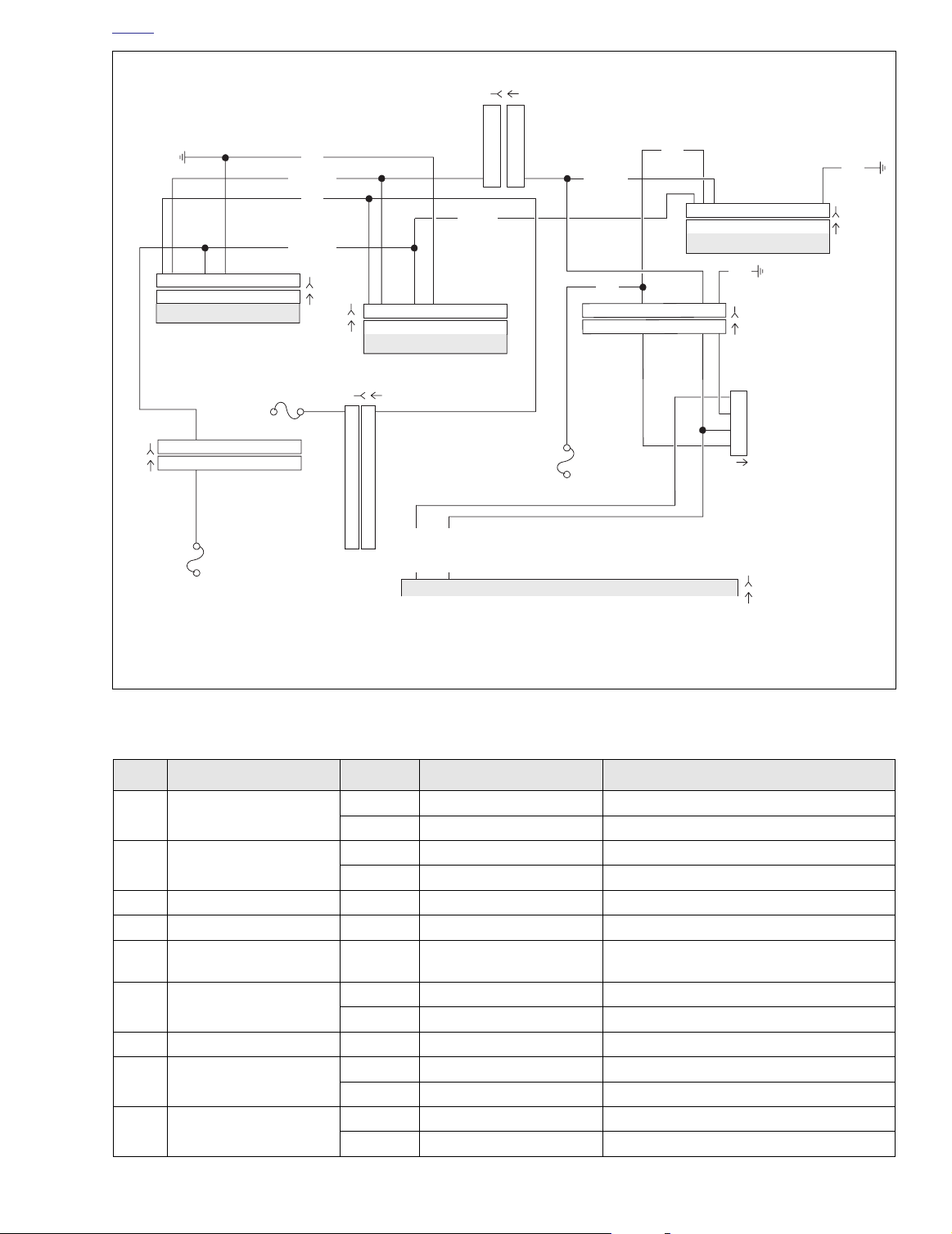
HOME
ECM
Data Link
TSM/TSSM
LtGN/V
15A
Ignition
Fuse
GY
[8B]
[8A]
[91A]
LtGN/V
BK
LtGN/V
[39B]
[39A]
[78B]
[78A]
Speedometer
O
BK
[108B]
[108A]
Tachometer
BN/GY
[156B] [156A]
[30B]
[30A]
15A
Accessory
Fuse
[1B] [1A]
Main to Interconnect
Harness
Ignition
Harness
Main to Interconnect
Harness
f2208u8x
15A
Battery
Fuse
[2B]
[2A]
Main to Interconnect
Harness
LtGN/R
BK
BN/GY
GY
Serial data
Flash pin
321654987121110
321654987121110
321654987121110
321654987121110
6
6
5
5
4
4
3
3
2
2
1
1
321654987121110
321654987121110
121110
987
65
4
32
1
1
65
4
32
121110
987
NO. DESCRIPTION MODEL TYPE LOCATION
[1]
[2]
[8] Ignition Harness All 12-Place Deutsch Under Right Side Cover
[10] Ignition Control Module All 12-Place Deutsch Under Right Side Cover
[30]
[39] Speedometer
[91] Data Link All 4-Place Deutsch Under Right Side Cover
[108] Tachometer
[156]
321654987121110
321654987121110
Main to Interconnect
Harness
Main to Interconnect
Harness
Table 2-26. Wire Harness Connectors in Figure 2-38.
Tu rn Signal/Security
Module
Main to Interconnect
Harness
123
123
6
6
101112 78945
101112 78945
51
Figure 2-38. Serial Data Circuit: FLTR, FLHT/C/U (Fuel Injected)
FLHT/C 12-Place Deutsch (Black) Inner Fairing - Right Radio Support Bracket
FLTR 12-Place Deutsch (Black) Inner Fairing - Below Radio (Left Side)
FLHT/C 12-Place Deutsch (Gray) Inner Fairing - Right Fairing Support Brace
FLTR 12-Place Deutsch (Gray) Inner Fairing - Below Radio (Left Side)
All 12-Place Deutsch
FLHT/C 12-Place Packard Inner Fairing (Back of Speedometer)
FLTR 12-Place Packard Under Bezel (Back of Speedometer)
Cavity in Crossmember at Rear of
Battery Box (Under Seat)
FLHT/C 12-Place Packard Inner Fairing (Back of Tachometer)
FLTR 12-Place Packard Under Bezel (Back of Tachometer)
FLHT/C 6-Place Deutsch Inner Fairing - Right Fairing Support Brace
FLTR 6-Place Deutsch Inner Fairing - Front of Right Fairing Bracket
2004 Touring: Instruments 2-45
1
2
3
4
Page 46

HOME
f2208t8x
BN/GY
321654987121110
321654987121110
Speedometer
15A
Battery
Fuse
BK
15A
Accessory
Fuse
LtGN/V
BN/GY
O
[39B]
[39A]
15A
Ignition
Fuse
LtGN/V
GY
3
21
321
GY
BK
321654987121110
321654987121110
[30B]
[30A]
TSM/TSSM
BK
98
7
65
4
98
7
65
4
121110
[8B]
Ignition
[8A]
Harness
121110
1
2
3
4
Data Link
[91A]
LtGN/V
LtGN/R
[78B]
[78A]
1
Flash pin
5
Serial data
ECM
Figure 2-39. Serial Data Circuit: FLHR/C/S (Fuel Injected)
Table 2-27. Wire Harness Connectors in Figure 2-39.
NO. DESCRIPTION TYPE LOCATION
[8] Ignition Harness 12-Place Deutsch Under Right Side Cover
[10] Ignition Control Module 12-Place Deutsch Under Right Side Cover
[30] Turn Signal/Security Module 12-Place Deutsch
[39] Speedometer 12-Place Mini-Deutsch Under Console (Back of Speedometer)
[78] Electronic Control Module 36-Place Packard Under Right Side Cover
[91] Data Link 4-Place Deutsch Under Right Side Cover
Cavity in Crossmember at Rear of
Battery Box (Under Seat)
2-46 2004 Touring: Instruments
Page 47

HOME
Test 2.14
LOSS OF TSM/TSSM SERIAL DATA: DTC U1064,
U1255
Can you read TSM/TSSM hardware P/N?
See 2.3 SPEEDOMETER SELF DIAGNOSTICS.
YES
Install Breakout Box on speedometer.
1
While wiggling harness, check for continuity
between terminal 3 (gray) and terminal 2
(black) of Breakout Box.
Continuity present?
YES
Clear codes. Test ride.
Does DTC U1064
return?
YES
Replace TSM/TSSM.
Learn password.
NO
Repair intermittent
on LtGN/V wire.
NO
No trouble found.
NO or “No Rsp”
Install Breakout Box on speedometer.
1
Check for continuity between terminal 3
(gray) and terminal 2 (black) of Breakout
YES
Replace TSM/TSSM.
Learn password.
Clear codes using speedometer self diagnostics.
See 2.3 SPEEDOMETER SELF DIAGNOSTICS.
Confirm proper operation with no check engine
lamp.
Box
Continuity present?
Repair open on
NO
LtGN/V wire.
2004 Touring: Instruments 2-47
Page 48

HOME
DTC U1300, U1301 OR “BUS ER” 2.15
GENERAL
Serial Data Low or Serial data Open/High
See Figure 2-40. The typical serial data voltage range is 0
volts (inactive) to 7 volts (active). Due to the short pulse, voltages will be much lower on a DVOM. In analog mode, a
DVOM reading serial data will show continuous voltage when
active, typically 0.6-0.8 volts. The range for acceptable operations is 0-7.0 volts.
Table 2-28. Code Description
DTC DESCRIPTION
U1300 Serial data low
U1301 Serial data open/high
DIAGNOSTICS
Diagnostic Tips
● If serial data is shorted, these diagnostic trouble codes
(DTCs) will automatically cause the check engine lamp
to illuminate. The odometer will read “Bus Er” in this condition.
● Diagnostic trouble codes (DTCs) P1009 and P1010 may
accompany DTCs U1300 and U1301.
Diagnostic Notes
● If a U1300, U1301 or “BUS Er” is present on carbureted
models, perform diagnostic procedures listed in 4.10
STARTS, THEN STALLS.
● If a U1300, U1301 or “BUS Er” is present on EFI models,
perform diagnostic procedures listed in 5.12 STARTS,
THEN STALLS.
Carbureted
f1917x9x
Fuel Injected
f2191x8x
Data Link
Connector [91]
Data Link
Connector [91]
2-48 2004 Touring: Instruments
Figure 2-40. Electrical Bracket (Under Right Side Cover)
 Loading...