

Page 1
HOME
INDUCTION MODULE ASSEMBLY 9.5
GENERAL
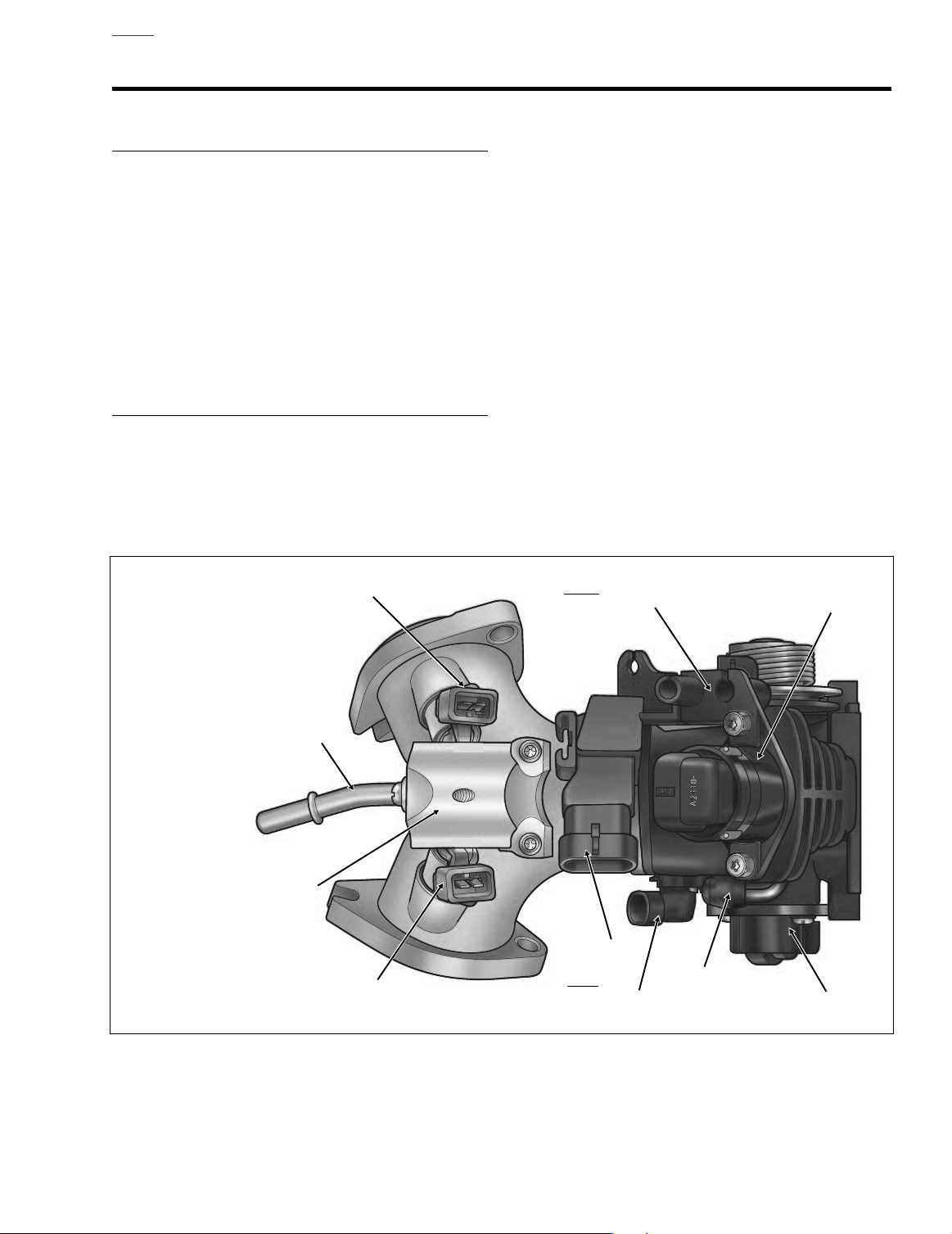
See Figure 9-23. The Induction Module Assembly consists of
the following components:
●
Induction Module
Fuel Supply Line
●
Fuel Rail/Fuel Supply Tube
●
●
Fuel Injectors
●
Intake Air Temperature Sensor
Throttle Position Sensor
●
Manifold Absolute Pressure Sensor
●
●
Idle Air Control
INDUCTION MODULE
REMOVAL
1. Partially remove fuel tank. See Section 9.4 FUEL TANK
(FUEL INJECTED), PA RTIAL REMOVAL, either FLHT/
C/U/I, FLTRI or FLHR/C/S/I.
1. Fuel Injector (Front)
2. Throttle Cable Bracket
3. Idle Air Control
4. Throttle Position Sensor
5. Purge Tube Fitting
(California Models Only)
6. Intake Air Temperature Sensor
7. Manifold Absolute Pressure
Sensor
8. Fuel Injector (Rear)
9. Fuel Rail
10. Fuel Supply Tube
10
1
2. Remove air cleaner and backplate. See Section 4.5 AIR
CLEANER, REMOVAL.
3. Pull purge tube from fitting at top of induction module
(California models only). See Figure 9-23.
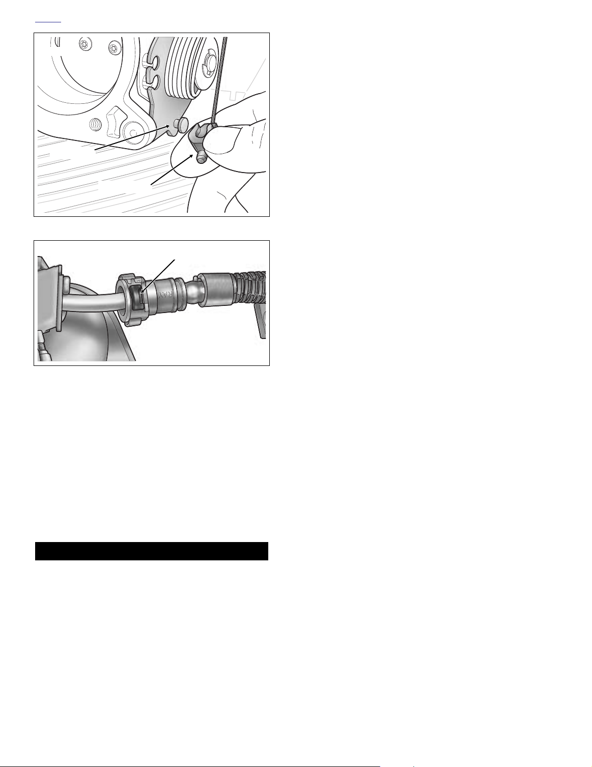
4. Using a needle nose pliers, carefully pull idle cable barrel from upper hole in throttle wheel. Pull throttle cable
barrel from lower hole. Using slots, release idle and
throttle cables from guides in throttle cable bracket.
5. On cruise control equipped models, remove E-clip from
sleeve at end of cruise cable housing. Using slot,
remove cable housing from cable guide in throttle cable
bracket. Push the plastic end fitting on the cruise cable
to the outboard side to release from wheel pin. See Fig-
ure 9-24.
6. Remove idle air control and manifold absolute pressure
sensor connectors. Pull external latch(es) outward and
use rocking motion to separate pin and socket halves.
7. Depress wire form to remove electrical connectors from
front and rear fuel injectors.
8. Remove throttle position sensor and intake air temperature sensor connectors.
Front
2
3
f2162x9x
9
7
8
Figure 9-23. Induction Module Assembly
Rear
6
5
4
2004 Touring: Fuel Injection 9-27
Page 2
HOME
f1965x8x
Wheel Pin
End Fitting
Figure 9-24. Remove End Fitting From Wheel Pin
Button
f1922x9x
Figure 9-25. Remove Fuel Supply Line From Supply Tube
9. Remove right side allen head socket screws from front
and rear cylinder head flange adapters. For best results,
use a long 1/4 inch ball allen head socket with end driver
4 inches long.
10. Moving to opposite side of vehicle, just loosen left side
allen head socket screws from flange adapters. Slots in
flanges make removal of left side screws unnecessary.
To better access bolts, loosen acorn nut and swing horn
assembly out of the way.
11. Slide induction module out from right side of vehicle.
Use caution around horn bracket to prevent damage to
fuel line.
1WARNING1WARNING
A small amount of gasoline will drain from the fuel supply line when disconnected from the supply tube. Thoroughly wipe up any spilled fuel immediately. Dispose of
rags in a suitable manner. Gasoline is extremely flammable and highly explosive. Inadequate safety precautions
could result in death or serious injury.
12. Depress button on inboard side of fuel supply line and
remove from supply tube. See Figure 9-25.
13. Remove seals from flange adapters. Discard seals.
Remove flange adapters from outlet ports of induction
module.
14. If it should become necessary to split the induction module, that is, separate the throttle body from the intake
manifold, proceed as follows:
a. Remove top and bottom T20 TORX screws to sepa-
rate intake manifold and throttle body flanges.
b. Remove O-ring from counterbore of throttle body
flange. Discard O-ring.
INSTALLATION
1. If induction module was split, assemble the intake manifold and throttle body as follows:
a. Apply a thin coat of clean engine oil to
Install O-ring in counterbore of throttle body flange.
Mate intake manifold and throttle body flanges.
b. Apply Loctite Wicking Threadlocker 290 (green) to
threads of two T20 TORX screws. Install screws and
alternately tighten to 27-33
Allow approximately 3-6 hours to elapse for compound to cure.
2. Slide fuel supply line onto tube at top of induction module. A slight tug will verify that the line is locked in place.
3. Orientate the induction module as shown in Figure 9-23.
With the counterbore facing outward, slide cylinder head
flange adapters onto outlet ports of induction module.
The flange adapters are not interchangeable. Look next
to the slotted bolt hole for a stamp that indicates F(ront)
and R(ear) cylinder.
4. Place a
eled side in against the counterbore.
5. Standing on right side of engine, slide induction module
toward installed position so that open-ended slots on
flange adapters begin to engage allen head socket
screws loosely installed on left side. Use caution around
horn bracket to prevent damage to fuel line.
6. Install sleeve on throttle cable housing into shorter cable
guide at top of throttle cable bracket. Drawing throttle
cable downward, fit barrel end into lower hole in throttle
wheel. Install sleeve and spring on idle cable housing
into longer cable guide at bottom of throttle cable bracket
inserting barrel end into upper hole in throttle wheel.
7. On cruise control equipped models, slide groove in
cruise cable end fitting over cap of wheel pin. Push on
end fitting until it snaps in place. Using slot, slip cruise
cable housing into cable guide in throttle cable bracket.
Install
ing.
8. Align fixed holes in flange adapters with those in cylinder
heads and start allen head socket screws. For best
results, use a long 1/4 inch ball allen head socket with
end driver 4 inches long.
new
seal in each flange adapter with the bev-
new
E-clip on sleeve at end of cruise cable hous-
in-lbs
new
O-ring.
(3.1-3.7 Nm).
9-28 2004 Touring: Fuel Injection
Page 3
HOME
1WARNING1WARNING
1WARNING1WARNING
f1966x9x
T27 TORX
f2079x9x
Screws
Breather Bolts
Backplate
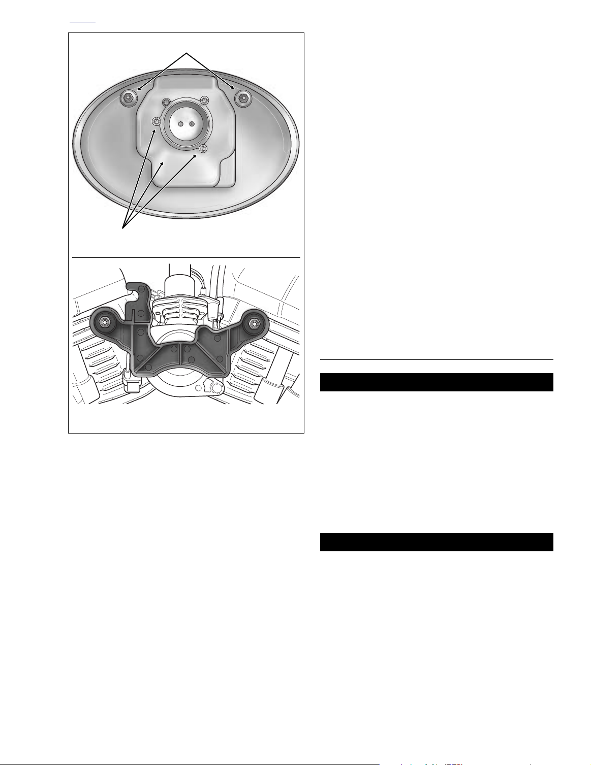
11. Remove breather bolts and T27 TORX screws to remove
backplate, if installed.
12. Tighten allen head socket screws in fixed holes of flange
adapters to 96-144
13. Remove breather bolts to remove alignment bracket, if
installed.
14. Install electrical connectors on fuel injectors.
15. Install manifold absolute pressure sensor and idle air
control connectors.
16. Install intake air temperature sensor and throttle position
sensor connectors.
17. Connect purge tube to fitting at top of induction module
(California models only). See Figure 9-23.
18. Install fuel tank. See Section 9.4 FUEL TANK (FUEL
INJECTED), INSTALLATION (AFTER PARTIAL
REMOVAL), FLHT/C/U/I, FLTRI or FLHR/C/S/I.
19. Turn the Ignition/Light Key Switch to ON and then back
to OFF to reset idle air control to park position.
20. Install backplate and air cleaner. See Section 4.5 AIR
CLEANER, INSTALLATION.
21. Check throttle and idle control cable adjustment. Check
cruise cable adjustment.
in-lbs
(10.9-16.3 Nm).
Bracket
Figure 9-26. Install Backplate or Bracket
9. Use the air cleaner backplate or INDUCTION SYSTEM
ALIGNMENT BRACKET (P&A Part No. 40054-01) to
properly locate induction module. Proceed as follows:
a.
Backplate
plate to front and rear cylinder heads. Install three
T27 TORX screws to secure backplate to face of
induction module. See upper frame of Figure 9-26.
b.
Alignment bracket
into holes in face of induction module, install two
breather bolts to fasten bracket to front and rear cylinder heads. See lower frame of Figure 9-26.
10. Tighten allen head socket screw in fixed holes of flange
adapters until snug. Moving to left side of engine, tighten
screws in slotted holes to 96-144
If moved, swing horn assembly back into position and
tighten acorn nut.
: Install two breather bolts to fasten back-
: Fitting pins on inboard side
in-lbs
(10.9-16.3 Nm).
FUEL SUPPLY LINE
The gasoline in the fuel supply line downstream of the
fuel pump is under high pressure (58 psi). To avoid an
uncontrolled discharge or spray of gasoline, always
purge the system of high pressure gas before the fuel
supply line is disconnected. Inadequate safety precautions could result in death or serious injury.
REMOVAL
1. Partially remove fuel tank. See Section 9.4 FUEL TANK
(FUEL INJECTED), PARTIAL REMOVAL, FLHT/C/U/I,
FLTRI or FLHR/C/S/I.
A small amount of gasoline will drain from the fuel supply line when disconnected from the fuel tank. Thoroughly wipe up any spilled fuel immediately. Dispose of
rags in a suitable manner. Gasoline is extremely flammable and highly explosive. Inadequate safety precautions
could result in death or serious injury.
NOTE
Check valve in the fuel tank fitting impedes any further fuel
seepage once external fuel line has drained.
2004 Touring: Fuel Injection 9-29
Page 4

HOME
Button
f1922x9x
Figure 9-27. Remove Fuel Supply Line From Supply Tube
2. Pull up on chrome sleeve of quick-connect fitting on left
side of fuel tank and pull down on fuel supply line to disconnect. See Figure 9-24.
3. Raise fuel tank approximately 2 inches. Move the fuel
tank crossover hose to the rear of the ignition coil, so
that the tank can be raised an additional 2-3 inches.
Move fuel tank straight back slightly and rest on frame
backbone.
4. Obtain several 1 x 2 inch wooden blocks. Raise the front
and rear of the fuel tank off the frame backbone by placing blocks in the recess centered at the bottom of the
tank.
FUEL RAIL/FUEL SUPPLY TUBE
REMOVAL
1. See INDUCTION MODULE, REMOVAL, in this section.
2. Depress button on inboard side of fuel supply line and
remove from fuel supply tube. See Figure 9-27.
3. Using a T20 TORX drive head, remove screw to release
fuel supply tube clamp. See Figure 9-28.
4. Gently pull fuel supply tube from fuel rail. Remove sealing washer from end of fuel supply tube. Remove O-ring
from fuel rail bore. Discard sealing washer and O-ring.
Fuel Supply
Tube Clamp
1WARNING1WARNING
A small amount of gasoline will drain from the fuel supply line when disconnected from the supply tube at the
top of the induction module. Thoroughly wipe up any
spilled fuel immediately. Dispose of rags in a suitable
manner. Gasoline is extremely flammable and highly
explosive. Inadequate safety precautions could result in
death or serious injury.
5. Depress button on inboard side of fuel supply line and
remove from supply tube. See Figure 9-27.
INSTALLATION
1. Slide fuel supply line onto tube at top of induction module. A slight tug will verify that the line is locked in place.
See Figure 9-27.
2. Pull up on chrome sleeve of quick-connect fitting on left
side of tank and insert neck of fuel supply line fitting.
While pushing up on bottom of fuel supply line fitting,
pull down on chrome sleeve until it “clicks” into the
locked position. Tug on fuel supply line to be sure that it
will not come free.
3. Install fuel tank. See Section 9.4 FUEL TANK (FUEL
INJECTED), INSTALLATION (AFTER PARTIAL
REMOVAL), FLHT/C/U/I, FLTRI, or FLHR/C/S/I.
9407
Figure 9-28. Remove Fuel Supply Tube Clamp
T20 TORX
Screws
Fuel Rail
8495
Figure 9-29. Remove Fuel Rail
9-30 2004 Touring: Fuel Injection
Page 5

HOME
Electrical
Connector
O-Ring
f1934x9x
Sealing
O-Ring
Figure 9-30. Install Fuel Supply Tube
5. Using a T20 TORX drive head, remove two screws to
release fuel rail from induction module. See Figure 9-29.
6. Pull fuel rail with attached fuel injectors from induction
module. To overcome the resistance of the bottom Oring on both fuel injectors, gently rock assembly back
and forth while pulling.
7. Pull fuel injectors from fuel rail. To overcome the resistance of the top O-ring, gently rock each fuel injector
while pulling.
8. Remove O-rings from fuel injectors. Discard O-rings.
See Figure 9-31.
Washer
f1935x9x
FUEL INJECTORS
REMOVAL
1. See INDUCTION MODULE, REMOVAL, in this section.
2. Depress button on inboard side of fuel supply line and
remove from fuel supply tube. See Figure 9-27.
3. Using a T20 TORX drive head, remove screw to release
fuel supply tube clamp. See Figure 9-28.
4. Using a T20 TORX drive head, remove two screws to
release fuel rail from induction module. See Figure 9-29.
5. Pull fuel rail with attached fuel injectors from induction
module. To overcome the resistance of the bottom Oring on both fuel injectors, gently rock assembly back
and forth while pulling.
6. Pull fuel injectors from fuel rail. To overcome the resistance of the top O-ring, gently rock each fuel injector
while pulling.
7. Remove O-rings from fuel injectors. Discard O-rings.
See Figure 9-31.
INSTALLATION
INSTALLATION
1. Apply a thin coat of clean engine oil to
rings. Install O-rings on fuel injectors. See Figure 9-31.
2. With the electrical connector topside, push fuel injectors
into induction module bores. Rotate fuel injectors, so
that the electrical connectors are on the outboard side.
3. Push fuel rail over fuel injectors until fuel rail flange contacts boss on induction module.
4. Using a T20 TORX drive head, install two screws to fas-
ten fuel rail to induction module. Alternately tighten
screws to 27-33
5. Note the collar on each end of the fuel supply tube. Slide
a
new
sealing washer down the shorter neck until it contacts the collar. Slide a
contacts the sealing washer. See Figure 9-30. Push tube
into fuel rail bore until collar is flush with casting.
6. Align hole in fuel supply tube clamp with hole in fuel rail.
Using a T20 TORX drive head, install screw and tighten
to 27-33
fuel supply tube so that it angles downward.
7. See INDUCTION MODULE, INSTALLATION, in this sec-
tion.
in-lbs
(3.0-3.7 Nm). See Figure 9-29.
new
o-ring down the tube until it
in-lbs
(3.0-3.7 Nm). See Figure 9-28. Rotate
new
injector O-
1. Apply a thin coat of clean engine oil to
rings. Install O-rings on fuel injectors. See Figure 9-31.
2. With the electrical connector topside, push fuel injectors
into induction module bores. Rotate fuel injectors, so
that the electrical connectors are on the outboard side.
3. Push fuel rail over fuel injectors until fuel rail flange contacts boss on induction module.
4. Using a T20 TORX drive head, install two screws to fasten fuel rail to induction module. Alternately tighten
screws to 27-33
in-lbs
(3.0-3.7 Nm). See Figure 9-29.
Figure 9-31. Fuel Injector
new
injector O-
2004 Touring: Fuel Injection 9-31
Page 6

HOME
5. Align hole in fuel supply tube clamp with hole in fuel rail.
Using a T20 TORX drive head, install screw and tighten
to 27-33
fuel supply tube so that it angles downward.
6. See INDUCTION MODULE, INSTALLATION, in this sec-
tion.
in-lbs
(3.0-3.7 Nm). See Figure 9-28. Rotate
INTAKE AIR TEMPERATURE SENSOR
8495
REMOVAL
1. Remove maxi-fuse. See Section 8.3 SYSTEM FUSES,
MAXI-FUSE, REMOVAL.
2. Remove air cleaner and backplate. See Section 4.5 AIR
CLEANER, REMOVAL.
3. Disconnect the intake air temperature sensor connector.
See Figure 9-32. Pull external latches outward and use
a rocking motion to separate pin and socket halves.
4. Using a T10 TORX drive head, remove two screws to
release intake air temperature sensor from induction
module. See Figure 9-32.
5. Remove and discard gasket.
INSTALLATION
1. Place
2. Insert sensor into induction module with electrical con-
3. Using a T10 TORX drive head, install two screws to
4. Install the intake air temperature sensor connector.
5. Install backplate and air cleaner. See Section 4.5 AIR
6. Install maxi-fuse. See Section 8.3 SYSTEM FUSES,
new
gasket on flange of intake air temperature
sensor.
nector facing toward the left side of the vehicle. See Fig-
ure 9-32.
secure intake air temperature sensor to induction module. Alternately tighten screws to 12
See Figure 9-32.
CLEANER, INSTALLATION.
MAXI-FUSE, INSTALLATION.
in-lbs
(1.4 Nm).
Intake Air
Temperature
Sensor
Figure 9-32. Induction Module (Rear View)
f1936x9x
Figure 9-33. Intake Air Temperature Sensor
3. Disconnect the throttle position sensor connector. See
Figure 9-32. Pull external latch outward and use a rock-
ing motion to separate pin and socket halves.
4. Using a T20 TORX drive head, remove two screws to
release sensor from induction module. See Figure 9-32.
Throttle
Position
Sensor
Thermistor
Gasket
INSTALLATION
THROTTLE POSITION SENSOR
REMOVAL
1. Remove maxi-fuse. See Section 8.3 SYSTEM FUSES,
MAXI-FUSE, REMOVAL.
2. Remove air cleaner and backplate. See Section 4.5 AIR
CLEANER, REMOVAL.
9-32 2004 Touring: Fuel Injection
1. With electrical connector facing down, fit pocket of throttle position sensor over throttle shaft.
2. Align holes in flange of throttle position sensor with holes
in induction module. It may be necessary to turn the sensor slightly to align holes.
3. Using a T20 TORX drive head, install two screws to
secure throttle position sensor to induction module.
Alternately tighten screws to 27-33
See Figure 9-32.
in-lbs
(3.0-3.7 Nm).
Page 7

HOME
8315
Throttle Cable
Bracket
T20 TORX
Screws
f1701x9x
Rubber
Seal
Electrical
Connector
Pressure Port
4. Using the throttle lever mechanism, open and close the
throttle plates to check for proper operation. Be sure that
the mechanism operates smoothly without binding or
sticking.
5. Install the throttle position sensor connector.
6. Install backplate and air cleaner. See Section 4.5 AIR
CLEANER, INSTALLATION.
7. Install maxi-fuse. See Section 8.3 SYSTEM FUSES,
MAXI-FUSE, INSTALLATION.
MANIFOLD ABSOLUTE PRESSURE SENSOR
REMOVAL
1WARNING1WARNING
The screw securing the throttle cable bracket and idle air
control flange to the induction module has a loctite
patch that may make it very difficult to remove. Since a
heat gun may be needed to break down the loctite,
remove induction module from vehicle, so that heat is
not applied close to fuel tank. Gasoline is extremely
flammable and highly explosive. Inadequate safety precautions could result in death or serious injury.
1. See INDUCTION MODULE, REMOVAL, in this section.
CAUTION
The idle air control screw has a loctite patch that may
make it very difficult to remove. If necessary, use a heat
gun to break down the loctite. Apply heat evenly around
screw head in a circular motion. Do not direct heat at idle
air control and other components or damage can occur.
2. Using a T20 TORX drive head, remove two screws to
release throttle cable bracket from induction module.
See Figure 9-34. Discard idle air control flange screw.
3. Pull pressure port from hole in induction module. See
Figure 9-35.
Figure 9-34. Remove Screws to Release Bracket
Figure 9-35. Manifold Absolute Pressure Sensor
3. Align hole in throttle cable bracket with hole at side of
induction module. Start screw into induction module.
See Figure 9-34.
4. Align hole at top of throttle cable bracket with thru hole in
flange of idle air control. Start
patch into induction module.
new
screw with loctite
INSTALLATION
1. If reusing sensor, inspect rubber seal on pressure port
for cuts, tears or signs of deterioration. Replace as necessary. See Figure 9-35.
2. With the electrical connector facing toward the rear of
the induction module (side opposite throttle cable
bracket), insert pressure port into hole in induction module.
5. Using a T20 TORX drive head, tighten screw at side of
throttle cable bracket to 27-33
6. Tighten flange screw of idle air control to 25
Nm).
7. Move free end of throttle return spring into slot in throttle
cable bracket. See Figure 9-34.
8. See INDUCTION MODULE, INSTALLATION, in this sec-
tion.
2004 Touring: Fuel Injection 9-33
in-lbs
(3.0-3.7 Nm).
in-lbs
(2.8
Page 8

HOME
IDLE AIR CONTROL
REMOVAL
1WARNING1WARNING
The screws securing the idle air control flange to the
induction module have a loctite patch that may make
them very difficult to remove. Since a heat gun may be
needed to break down the loctite, remove induction
module from vehicle, so that heat is not applied close to
fuel tank. Gasoline is extremely flammable and highly
explosive. Inadequate safety precautions could result in
death or serious injury.
1. See INDUCTION MODULE, REMOVAL, in this section.
CAUTION
The idle air control screws have a loctite patch that may
make them very difficult to remove. If necessary, use a
heat gun to break down the loctite. Apply heat evenly
around screw head in a circular motion. Do not direct
heat at idle air control and other components or damage
can occur.
2. Using a T20 TORX drive head, remove two screws to
release throttle cable bracket from induction module.
See Figure 9-34. Discard flange screw of idle air control.
3. Remove remaining screw to release flange of idle air
control from top of induction module. Discard screw.
4. Pull idle air control from bore of induction module.
5. Remove O-ring from body of idle air control. Discard Oring. See Figure 9-37.
Idle Air
Control
Figure 9-36. Induction Module (Rear View)
f1938x9x
O-Ring
Figure 9-37. Idle Air Control
8495
INSTALLATION
1. Apply a thin coat of clean engine oil to
Install O-ring on counterbore of induction module flange.
2. With the electrical connector facing the left side of the
induction module (intake manifold side), install idle air
control into bore.
3. Align hole in throttle cable bracket with hole at side of
induction module. Start screw into induction module.
See Figure 9-34.
4. Align hole at top of throttle cable bracket with thru hole in
flange of idle air control. Start
patch into induction module.
5. Install remaining screw into flange of idle air control.
Again, use
6. Using a T20 TORX drive head, tighten screw at side of
throttle cable bracket to 27-33
9-34 2004 Touring: Fuel Injection
new
screw with loctite patch.
new
in-lbs
new
O-ring.
screw with loctite
(3.0-3.7 Nm).
7. Alternately tighten flange screws of idle air control to 25
in-lbs
(2.8 Nm).
8. Move free end of throttle return spring into slot in throttle
cable bracket.
9. See INDUCTION MODULE, INSTALLATION, in this sec-
tion.
Page 9

HOME
1. Throttle Position Sensor
2. T20 TORX Screw- 14mm (3)
3. T10 TORX Screw (2)
4. Intake Air Temperature Sensor
5. Gasket
6. O-Ring
7. Idle Air Control
8. T20 TORX/Hex Screw (2)
9. Throttle Cable Bracket
10. Fuel Injector
11. T20 TORX Screw- 17mm (5)
12. Fuel Rail
13. Fuel Supply Tube Clamp
14. Fuel Supply Tube
15. Sealing Washer
16. O-Ring
17. Manifold Absolute
Pressure Sensor
18. Rubber Seal
19. Socket Head Screw (4)
20. Flange Adapter (2)
3
4
2
6
5
21. Adapter Seal (2)
22. Intake Manifold
23. O-Ring
24. Throttle Body
10
8
7
11
13
14
11
15
16
10
12
9
2
17
18
19
20
1
f2161x9x
22
23
11
19
24
Figure 9-38. Induction Module Assembly
21
2004 Touring: Fuel Injection 9-35
Page 10

HOME
NOTES
9-36 2004 Touring: Fuel Injection
 Loading...