

Page 1

HOME
o0235xox
KEY FOB SIGNAL TO TSSM WEAK OR FAILS 3.14
GENERAL
Security Equipped Vehicles Only
This section applies only to those vehicles equipped with the
optional security system.
NOTE
Disarming function may require practice. The key fob button
must
be pressed twice within 1.5 seconds to send the disarm
command. The action is very similar to double-clicking a computer mouse. Light quick taps work best; very hard or very
slow taps are less likely to work.
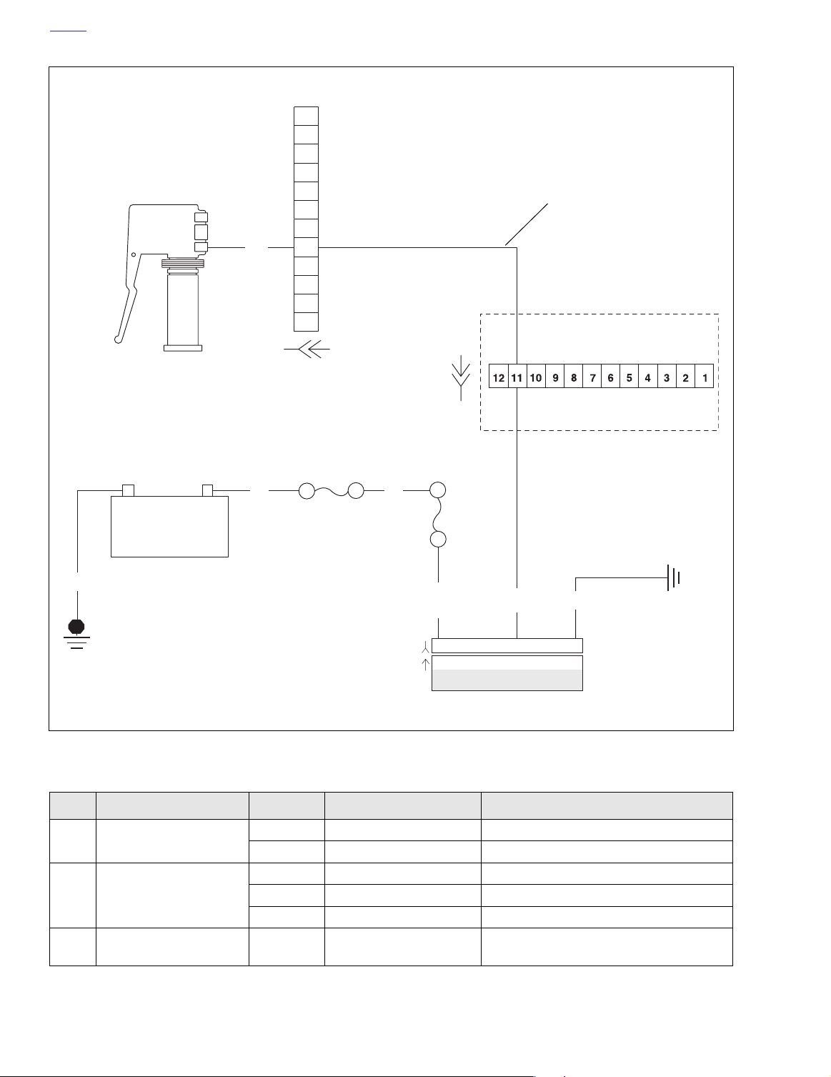
See Figure 3-24. The key fob sends a RF signal to activate all
remote TSSM functions. The left front turn signal switch wire
serves as the vehicle’s antenna. If the TSSM does not
respond (no confirmation at arming/disarming system) or
responds weakly (limited range, won’t consistently arm/disarm or synchronize), follow the Test 3.14 flow chart.
Diagnostic Notes
The reference numbers below correlate with the circled numbers on the Test 3.14 flow charts.
Figure 3-24. Key Fob Battery
DIAGNOSTICS
Diagnostic Tips
Verify key fob battery voltage is at least 2.9 volts. See
●
3.25 TSSM MAINTENANCE.
●
Interference from physical surroundings may affect RF
transmission. Place fob next to left handgrip and disarm
with two clicks or move motorcycle to a new location and
retest.
Check for damage to antenna wire. Does left turn signal
●
work?
NOTE
See 3.7 ARMING/DISARMING SECURITY SYSTEM
(TSSM). Use only the proper key fob for your market and
TSSM package.
1. After a battery disconnect, the TSSM will not enter the
configuration mode on the first attempt. All attempts to
assign a fob or enter the configuration mode will require
at least two attempts.
2004 Touring: TSM & TSSM 3-43
Page 2
HOME
f2208q8x
W/V
12
11
10
9
8
7
6-Place on FLHR/C/S
6
5
4
3
2
1
Also Functions as Key
Fob Antenna
All but FLHR/C/S
Left Turn Signal
–+
BK
Switch
Battery
[24B] [24A]
[1A]
[1B]
40 Amp
Maxi Fuse
R
R
15 Amp
Battery Fuse
BK
[30B]
[30A]
BN/GY
321654987121110
321654987121110
W/V
TSSM
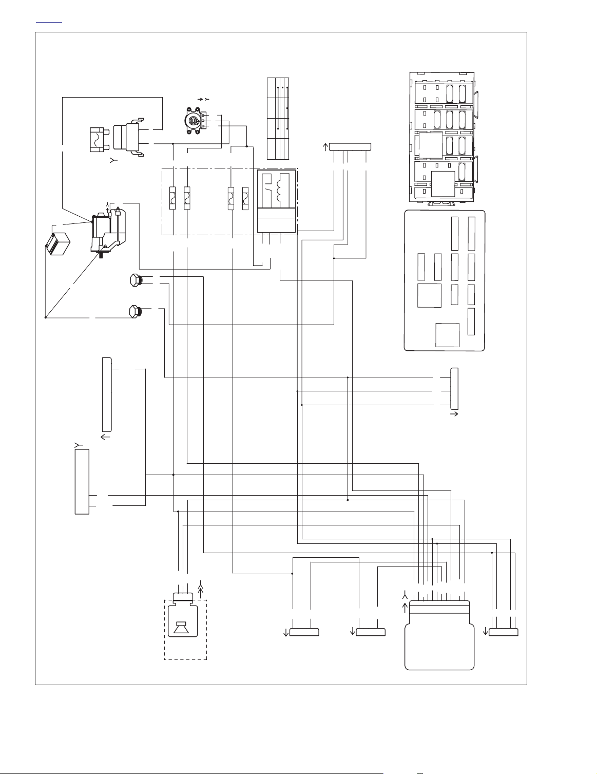
Figure 3-25. Antenna Circuit
Table 3-19. Wire Harness Connectors in Figure 3-25.
NO.
[1]
DESCRIPTION MODEL TYPE LOCATION
Main to Interconnect
Harness
FLHT/C 12-Place Deutsch (Black) Inner Fairing - Right Radio Support Bracket
FLTR 12-Place Deutsch (Black) Inner Fairing - Below Radio (Left Side)
FLHT/C/U 12-Place Deutsch Inner Fairing - Left Fairing Support Brace
Left Handlebar Switch
[24]
Controls
FLTR 12-Place Deutsch Inner Fairing - Left Side of Radio Bracket
FLHR/C/S 6-place Deutsch Inside Headlamp Nacelle
[30] TSSM All 12-Place Deutsch
3-44 2004 Touring: TSM & TSSM
Cavity in Crossmember
at Rear of Battery Box (Under Seat)
Page 3
HOME
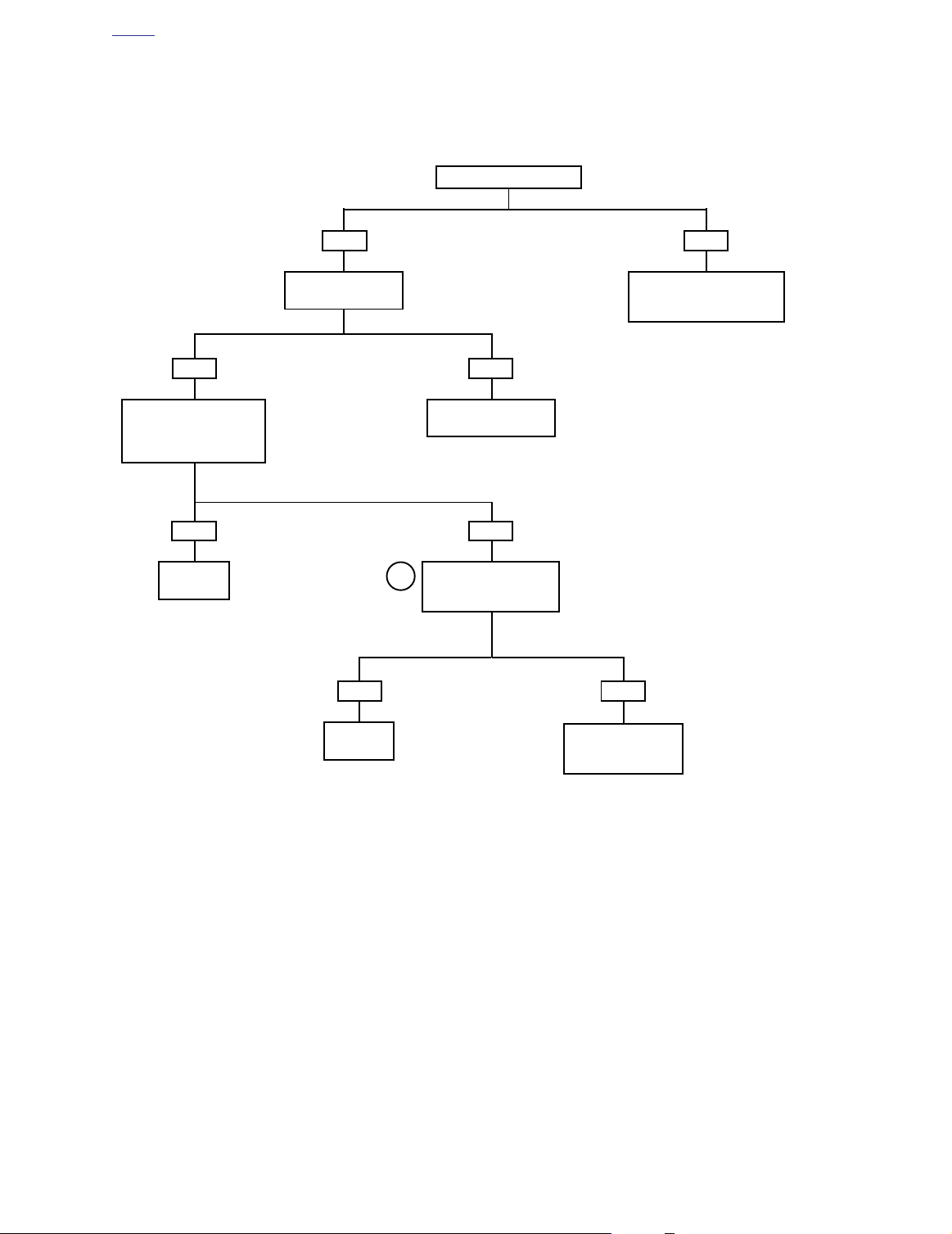
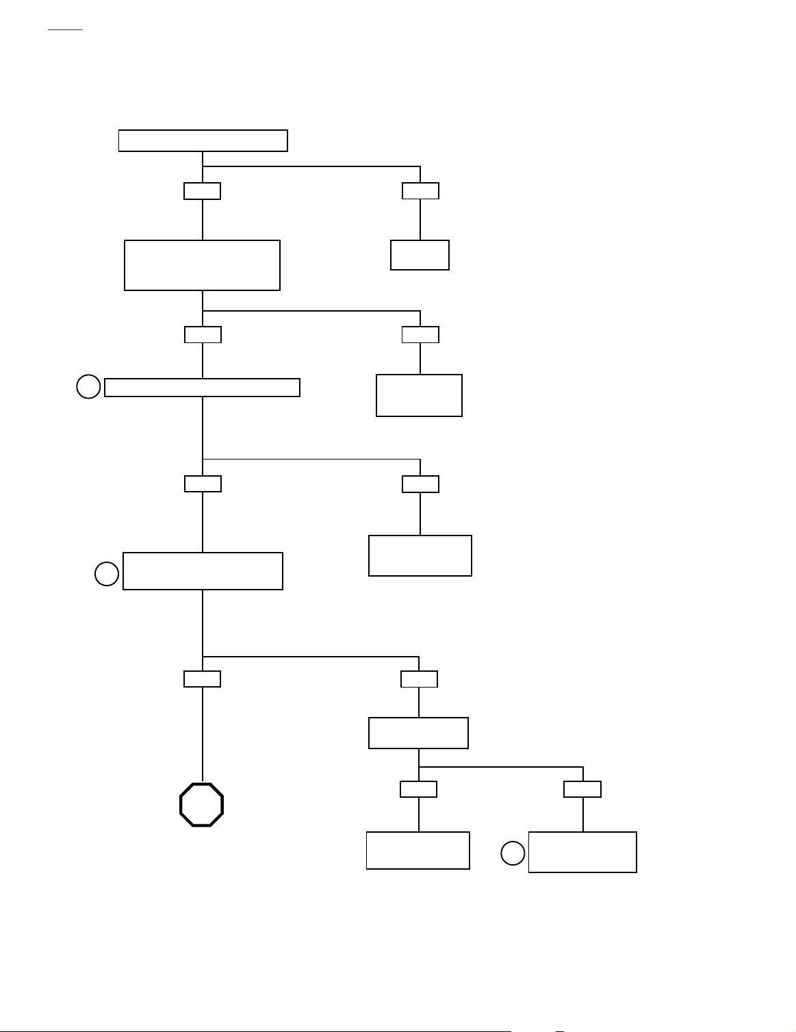
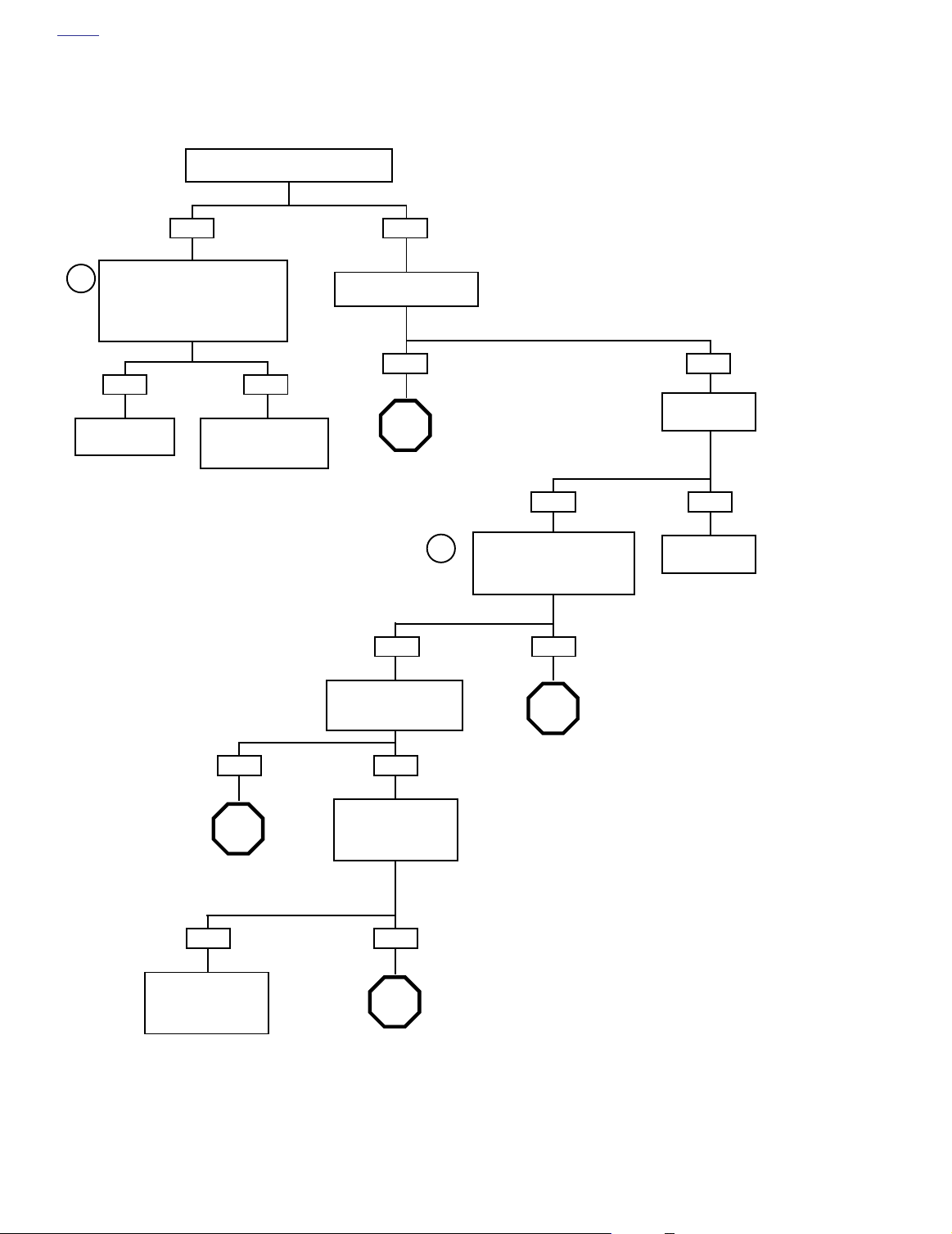
Test 3.14
FOB SIGNAL TO TSSM WEAK OR FAILS
Correct key fob for vehicle?
YES
Replace fob battery and
retest. See 3.25 TSSM
MAINTENANCE.
Does fob work?
YES
System
OK.
YES
Does left turn
signal function?
YES
See 3.15 TURN SIGNAL
ERRORS.
Attempt to assign new fob
1
to TSSM and retest.
Does fob work?
NO
NO
NO
Obtain correct fob or replace
fob. Verify fob is synchronized
to vehicle’s TSSM.
NO
System
OK.
Replace TSSM.
Learn password and
perform setup.
2004 Touring: TSM & TSSM 3-45
Page 4
HOME
TURN SIGNAL ERRORS 3.15
GENERAL
The turn signals will automatically cancel either based on the
speed/acceleration of the vehicle or based upon turn completion. See 3.4 TSM/TSSM TURN SIGNAL FUNCTIONS.
For turn signal diagnostics, refer to Table 3-20.
DIAGNOSTICS
Diagnostic Tips
●
Diagnostic trouble code DTC B1121 and B1122 will illuminate the security lamp.
DTC B1141 will not illuminate the security lamp.
●
When the TSM/TSSM is in four-way flasher mode, a fault
●
on either the left or right turn lamp output will not cause
either DTC B1121 and DTC B1122 to be set as current.
If fault occurs on both left and right outputs, then both
DTC B1121 and DTC B1122 will be set as current.
When the TSM/TSSM detects an over current (or short to
●
ground) condition, it will turn off the turn lamp outputs.
The outputs will be automatically reactivated once the
fault is removed.
7844
Figure 3-26. TSM/TSSM
Table 3-20. Turn Signal Errors
SYMPTOM
Tu rn signals will not cancel upon turn completion Turn S ignal Error 1A (Part 1 of 2) N/A
Tu rn signals cancel erratically Tur n S ignal Error 1A (Part 2 of 2) N/A
Tu rn signals will not flash, 4-way flashers inoperable Turn Signal Error 2A B1121, B1122, B1141
Left or right turn signals flash at double the normal rate
while all bulbs are working
START WITH
FLOW CHART
Tur n S ignal Error 3A N/A
DTC(S)
3-46 2004 Touring: TSM & TSSM
Page 5
HOME
f2208c8x
BETWEEN LEAD WIRES
"X" INDICATES CONTINUITY
SWITCH
IGNITION SWITCH LEGEND (HDI)
MAXI-FUSE
BK
BK
[142A]
SIREN
OPTIONAL SECURITY
RED/
BLACK
XX
RED/
GRAY
X
X
IN POSITION INDICATED
RED
IGN
OFF
ACC X X
LOCK X
POSITION
40 A
[5B]
R
GN
[128B]
[128A]
BATTERY
BK
GROUND
SIGNAL
POWER
A B C
[142B]
BK
LGN/BN
BN/GY
BK
[33D] [33C]
[33B]
B A
STARTER
123
R
R
R
R/GY
A
B
IGNITION
SWITCH, HDI
JUMPER HARNESS
R/BK
C
D
LEFTRIGHT
(LOCATED IN
GROUND STUD
868530
87
87A
[126B] [126A]
R
BK
R/BK
R
BK
BATTERY
3D 3C
[64B]
BN/GY
FRONT OF BATTERY)
R
R/GY
A
B
C
[33B]
A
B
C
[33A]
KEYSWITCH IGN RELAY
R
R/BK
R/GY
R/BK
IGNITION
1F 1E
GY
R/BK
D
D
RED/
BLACK
RED/
GRAY
BETWEEN LEAD WIRES
IN POSITION INDICATED
RED
"X" INDICATES CONTINUITY
IGNITION
SWITCH, DOM
858630
START RELAY
SUETK
TN/GN
LOCK X
SWITCH
IGNITION SWITCH LEGEND (DOM)
POSITION
[123A]
87
87A
[123B]
GN
BK/R
R/GY
XX
X
X
IGN
OFF
ACC X X
BN/V
LGN/V
RADIO MEM
RADIO PWR
IGN
BATTERY
P&A
BRAKE
RELAY
MAIN FUSE BLOCK
3
4
B
15A
10A
D
15A
F
BRAKE
RELAY
H
V
[39B]
12
11
10
9
8
67
5
34
2
1
BN
[7B]
TO REAR
LIGHTING
12345678
[7A]
NC
TRIP SWITCH
NC
FUEL LEVEL
TRIP SWITCH
GROUND
ACCESSORY
BATTERY
SECURITY LP
NC
DATAB US
IGNITION
CRUISE/BRK
ACCESS.
P&A
2
15A
15A
15A
1
A
15A
C
15A
E
15A
G
15A
J
INSTRUMENTS
LIGHTS
IGN
HEADLAMPS
SPEEDOMETER
V
GY
BN/V
LGN/V
BN/GY
123456789
IGNITION
BATTERY
LEFT TURN FEED
SECURITY INDICATOR
VSS/SERIAL DATA LINK
TSM/TSSM
BK
BN
W/V
W/BN
TN/GN
LGN/BN
101112
GROUND
ALARM SIGNAL
IGNITION ENABLE
RIGHT TURN FEED
LEFT TURN SW INPUT
RIGHT TURN SW INPUT
START RELAY CONTROL
[30B][30A]
(GY)
[8A]
MODULE
TURN SIGNAL/
TURN SIGNAL SECURITY
V
BN
W/V
LGN/V
101112
OR E.F.I.
TO CARB
IGNITION
HARNESS
[8B]
W/BN
123456789
101112
TO
[1A]
HARNESS
INTERCONNECT
(BK)
[1B]
123456789
101112
TO
INTERCONNECT
(2A)
HARNESS
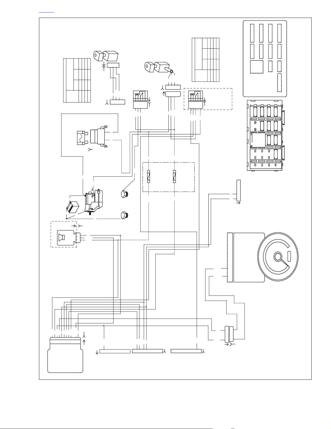
Figure 3-27. Turn Signal Circuit: FLTR, FLHT/C/U
BK/R
BN/V
LGN/V
123456
123456
[156B]
(GY)
[156A]
INTERCONNECT
HARNESS
[2B]
123456789
2004 Touring: TSM & TSSM 3-47
Page 6
HOME
BATTERY
f2208b8x
R
BK
40 A
MAXI-FUSE
STARTER
BK
BK
[128]
GN
[5B]
B A
RIGHT
LEFT
GROUND
R
R
STUDS
BK
[64B]
BK
BK
[33A]
(REAR VIEW)
SWITCH
IGNITION
R/BK
R
1E
3C
IGN: 15A
BATTERY 15A
1F
3D
GY
BN/GY
4
3
2
1
15A
2
5
RY
ATTE
B
A
15A
15A15A
C
15A
64
E
15A
15A15A
G
2
J
START
RELAY
5
CRUISE/BRK
INSTRUMENTS
SS.
E
LIGHTS
ACC
IGN
P&A
B RED
[33B]
R/BK
I
R
B
R/GY
A
R/GY
I RED/
BLACK
A RED/
GREY
IGNITION SWITCH LEGEND
OFF
IGNITION
POSITION
ACCESSORY
1234567
[7A]
BN
LIGHTS
TO REAR
V
BK
(7B)
8
BK
2C
START
P&A: 15A
ACCY: 15A
2D
5
3
2J3H3J
RELAY
1
2
2H
B
D
3
Y
KE
F
RELA
BRA
1
3
H
1
O/W
GN
R/GY
TN/GN
N
IG
P&A
Y
RELA
BRAKE
MAIN FUSE BLOCK
HEADLAMPS
START
RELAY
HARNESS
VEHICLES)
TO IGNITION
(CARBURETED
SPEEDOMETER
(EFI
OR TO
VEHICLES)
ECM HARNESS
[39B]
123456 789101112
123456789101112
BN/V
LGN/V
[8A]
LGN/V
BK
BN/GY
LGN/BN
A
B
C
SIGNAL
POWER
GROUND
SIREN
SECURITY
OPTIONAL
[142B]
[142A]
[24A]
O/W
1
2
345
HAND
TO LEFT
W/V
6
CONTROLS
[22A]
O/W
2
1
TO RIGHT
W/BN
345
HAND
CONTROLS
6
BK
BN
V
[30B]
V
BN
GY
BN/V
BN/GY
LGN/V
123456789
[30A]
MODULE
BATTERY
IGNITION
VSS / SERIAL DATA LINK
SECURITY INDICATOR
LEFT TURN FEED
RIGHT TURN FEED
TS/TSSM
TURN SIGNAL/SECURITY
LAMPS
TO INDICATOR
12345678
[21A]
BK
W/V
W/BN
TN/GN
LGN/BN
101112
RIGHT TURN SWITCH INPUT
LEFT TURN SWITCH INPUT
START RELAY CONTROL
IGNITION ENABLE SIGNAL
ALARM SIGNAL
GROUND
[31A]
BK
1
BN
2
345
TURN
TO FRONT
V
BK
6
SIGNALS
3-48 2004 Touring: TSM & TSSM
Figure 3-28. Turn Signal Circuit: FLHR/C/S
Page 7
hd41354
10095
45
o
45
o
HOME
Diagnostic Notes: All Turn Signal Flow Charts
The reference numbers below correlate with the circled numbers on the turn signal flow charts.
NOTE
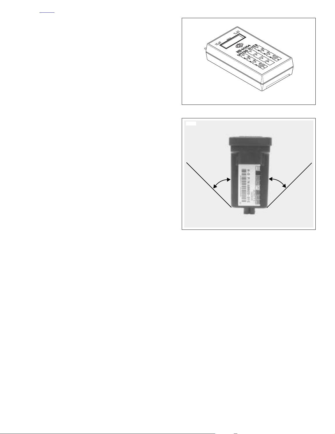
It is necessary to fabricate an adapter harness to connect the
SPEEDOMETER TESTER (Part No. HD-41354) to the 3place vehicle speed sensor connector [65]. See 2.6 SPEED-
OMETER PERFORMANCE CHECK for instructions on fabri-
cating this adapter harness.
1. Gain access to vehicle’s TSM/TSSM. Perform the following procedure:
a. See Figure 3-30. Position TSM/TSSM in same ori-
entation it is mounted on vehicle. Turn on ignition
switch. Turn on 4-way flashers by depressing both
left and right turn signal switches simultaneously.
Tu rn ignition off; 4-way flashers should continue to
flash.
b. Tilt module greater than 45 degrees to the left.
c. Repeat step a.
d. Tilt module greater than 45 degrees to the right.
2. Connect SPEEDOMETER TESTER (Part No. HD-
41354) to connector [65B]. Turn on ignition switch. set
RUN/STOP switch to the RUN position. Use SPEEDOMETER TESTER to input a signal which duplicates a
speed greater than or equal to 20 MPH (32.2 KPH).
Enter 528 into the tester. If turn signals are working correctly, they will flash 20 times and then cancel.
3. To enable diagnostic mode, see 3.10 SPEEDOMETER
SELF DIAGNOSTICS.
4. Connect BREAKOUT BOX (Part No. HD-42682) (gray)
between TSM/TSSM connector [30A] and wiring harness
connector [30B]. See 3.11 BREAKOUT BOX: TSM/
TSSM.
5. Closely inspect handlebar controls for pinched wiring.
6. Remove BREAKOUT BOX (Part No. HD-42682) (gray)
from between TSM/TSSM connector [30A] and wiring
harness connector [30B]. Reconnect [30].
7. Connect BREAKOUT BOX (Part No. HD-42682) (black)
between wiring harness connector [24A] and left hand
control harness connector [24B]. On FLHR/C/S use 6pin Harness Adapters (Part no. HD-42962) to mate handlebar controls to Breakout Box.
8. Connect BREAKOUT BOX (Part No. HD-42682) (black)
between wiring harness connector [22A] and right hand
control harness connector [22B]. On FLHR/C/S use 6pin Harness Adapters (Part no. HD-42962) to mate handlebar controls to Breakout Box.
9. Check for corrosion at rear lighting harness connector
[7], front lighting harness connector [31] and TSSM [30].
Figure 3-29. Speedometer Tester
Figure 3-30. Tilting TSM/TSSM
2004 Touring: TSM & TSSM 3-49
Page 8
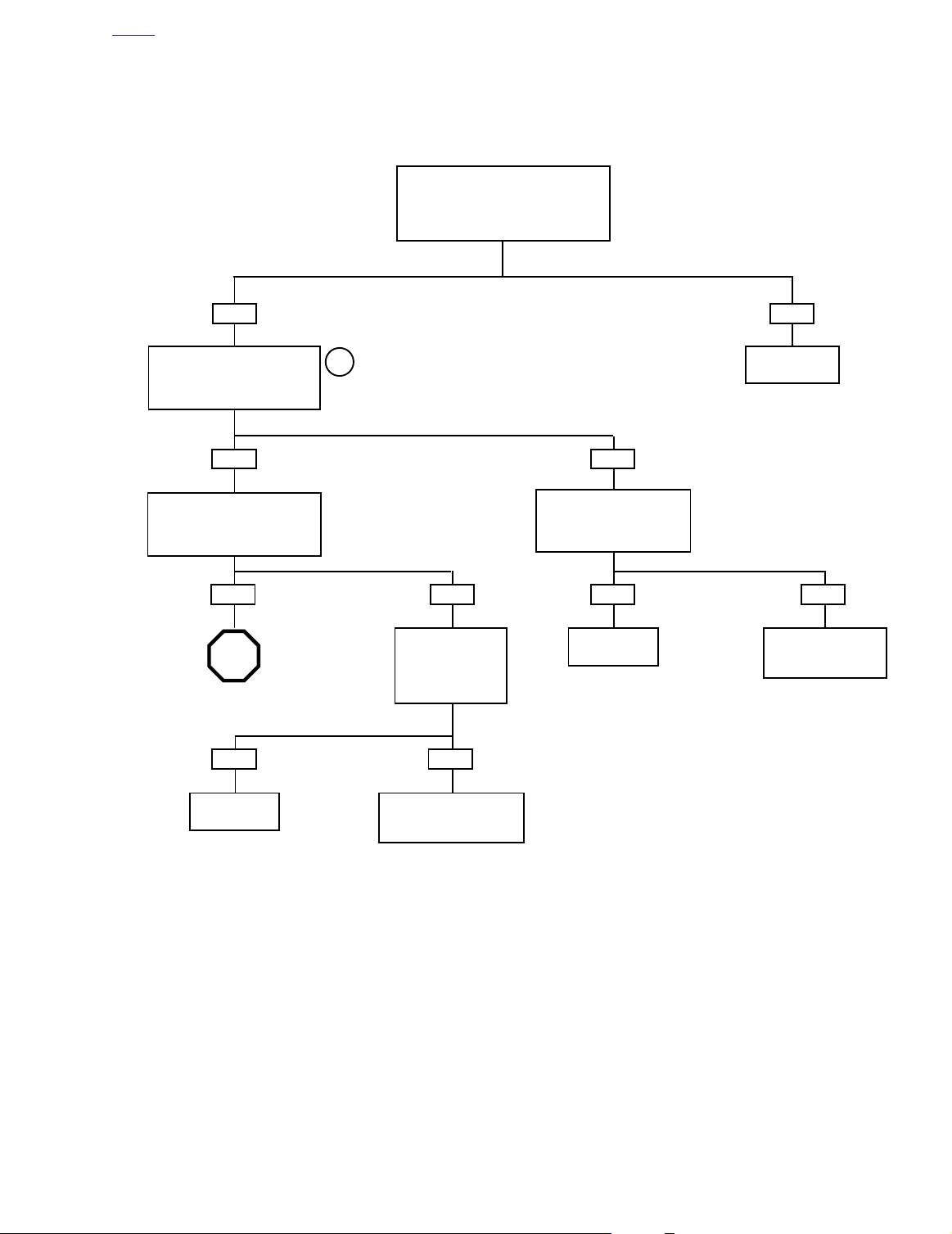
HOME
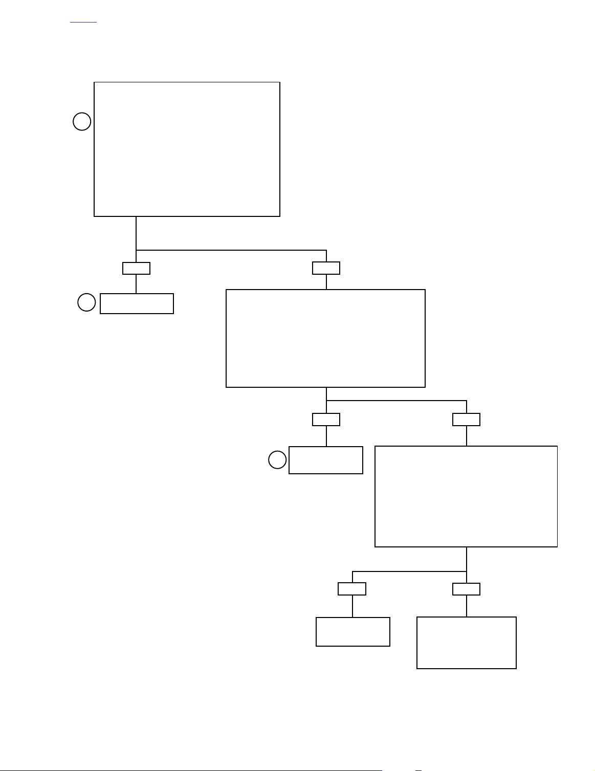
Turn Signal Error 1A (Part 1 of 2)
WILL NOT CANCEL UPON TURN COMPLETION
Is TSM/TSSM mounted properly?
YES
Check if TSM/TSSM is configured for
solo or side car operation. See 3.3
TSM/TSSM VEHICLE DELIVERY.
Proper configuration?
YES
Do 4-way flashers cancel in both directions?
1
YES
Activate either turn signal. Turn signals
should cancel after 20 flashes.
2
Do turn signals cancel?
NO
Mount
correctly.
NO
Select proper
vehicle
configuration.
NO
Replace TSM/TSSM.
Perform setup and
password learn.
YES
STOP
Go to Turn Signal
Error 1A (Part 2 of 2).
3-50 2004 Touring: TSM & TSSM
NO
Does speedometer
register vehicle speed?
Replace TSM/TSSM.
Perform password learn
and setup.
Refer to 2.2 INITIAL
DIAGNOSTIC CHECK:
3
SPEEDOMETER.
NOYES
Page 9
HOME
Turn Signal Error 1A (Part 2 of 2)
CANCELS ERRATICALLY
Continued from Turn Signal Error 1A (Part 1 of 2).
● Check for voltage between Breakout Box cavity 8
(gray) and ground at Breakout Box cavity 12 (gray):
4
with left turn signal switch depressed, wiggle harness
between TSM/TSSM and left handlebar switches while
monitoring for voltage fluctuations or changes in turn
signal flash pattern.
● Check for voltage between Breakout Box cavity 7
(gray) and ground at Breakout Box cavity 12 (gray):
with right turn signal switch depressed, wiggle harness
between TSM/TSSM and right handlebar switches
while monitoring for voltage fluctuations or changes in
turn signal flash pattern.
Are voltage fluctuations present?
5
YES
Locate and repair
intermittent open.
NO
● Check for voltage between Breakout Box cavity 8 (gray)
and ground at Breakout Box cavity 12 (gray): with left turn
signal switch NOT depressed, wiggle harness between
TSM/TSSM and left handlebar switches while monitoring
for voltage fluctuations or turn signal activation.
● Check for voltage between Breakout Box cavity 7 (gray)
and ground at Breakout Box cavity 12 (gray): with right turn
signal switch NOT depressed, wiggle harness between
TSM/TSSM and right handlebar switches while monitoring
for voltage fluctuations or turn signal activation.
Are voltage fluctuations present?
YES
Locate and repair
intermittent short to
5
voltage.
● Turn ignition switch OFF.
● Check for continuity between Breakout Box cavity 8
(gray) and ground at Breakout Box cavity 12 (gray):
with left turn signal switch depressed, wiggle harness
between TSM/TSSM and left handlebar switches.
● Check for continuity between Breakout Box cavity 7
(gray) and ground at Breakout Box cavity 12 (gray):
with right turn signal switch depressed, wiggle harness between TSM/TSSM and right handlebar
switches.
NO
Is continuity present at any time?
YES
Locate and repair
intermittent short to
ground.
NO
System OK.
Review turn signal cancellation
function with customer. See
AUTOMATIC CANCELLATION
under 3.4 TSM/TSSM TURN
SIGNAL FUNCTIONS.
2004 Touring: TSM & TSSM 3-51
Page 10
HOME
Turn Signal Error 2A
WILL NOT FLASH, 4-WAY FLASHERS INOPERABLE: DTC B1121, B1122, B1141
Turn ignition switch ON.
Are turn signal lamps on continuously?
YES NO
Check for voltage on Breakout Box
4
terminal 5 (gray) (left turn signals) or
terminal 6 (gray) (right turn signals)
with TSM/TSSM disconnected from
Locate and repair
short to voltage.
Breakout Box.
Is battery voltage present?
YES
NO
Replace TSM/TSSM.
Learn password and
perform setup.
Activate 4-way flashers.
Do any lamps illuminate?
YES NO
STOP
Go to Turn Signal
Error 2B.
YES
Connector [30]
mated fully?
NO
YES
STOP
Go to Turn Signal
Error 2D.
YES
Locate and repair
open on gray wire
between ignition fuse
and TSM/TSSM.
4
YES NO
Move red meter lead to
Pin 2 of connector [30].
Battery voltage present?
NO
Check for voltage at
ignition fuse. Battery
voltage present on both
terminals?
NO
STOP
For carbureted models,
go to 4.11 NO SPARK/NO
ICM POWER.
For EFI models go to
5.11 NO ECM POWER.
Place red meter lead at cavity 1
(gray) and black meter lead at
cavity 12 (gray) of Breakout Box.
Is battery voltage present?
STOP
Go to Turn Signal
Error 2C.
Mate
connector.
3-52 2004 Touring: TSM & TSSM
Page 11
HOME
Turn Signal Error 2B
WILL NOT FLASH, 4-WAY FLASHERS INOPERABLE: DTC B1121, B1122, B1141
Continued from Turn Signal Error 2A or
Turn Signal Error 2D.
Inspect bulbs on side that will not flash.
Are the bulbs OK?
YES
Place jumper wire between
Terminals 1 and 6 of Breakout
Box. Do the right turn signals (front
and rear) illuminate?
YES
Place a jumper wire between
Terminals 1and 5 of Breakout Box.
Do the left turn signals (front and
rear) illuminate?
YES
STOP
Go to Turn Signal
Error 3A.
YES
NO
6
NO
Check for continuity between
Terminal 6 of Breakout Box
and lamps (front and rear).
Continuity present?
NO
Check for continuity
between Terminal 5 of
Breakout Box and
lamps (front and rear).
Continuity present?
NO
YES
Repair open
ground circuit.
Replace bulbs
as necessary.
NO
Repair open between
lamps and TSM/TSSM
connector [30].
Repair open
ground circuit.
Repair open between
lamps and TSM/TSSM
connector [30].
2004 Touring: TSM & TSSM 3-53
Page 12
HOME
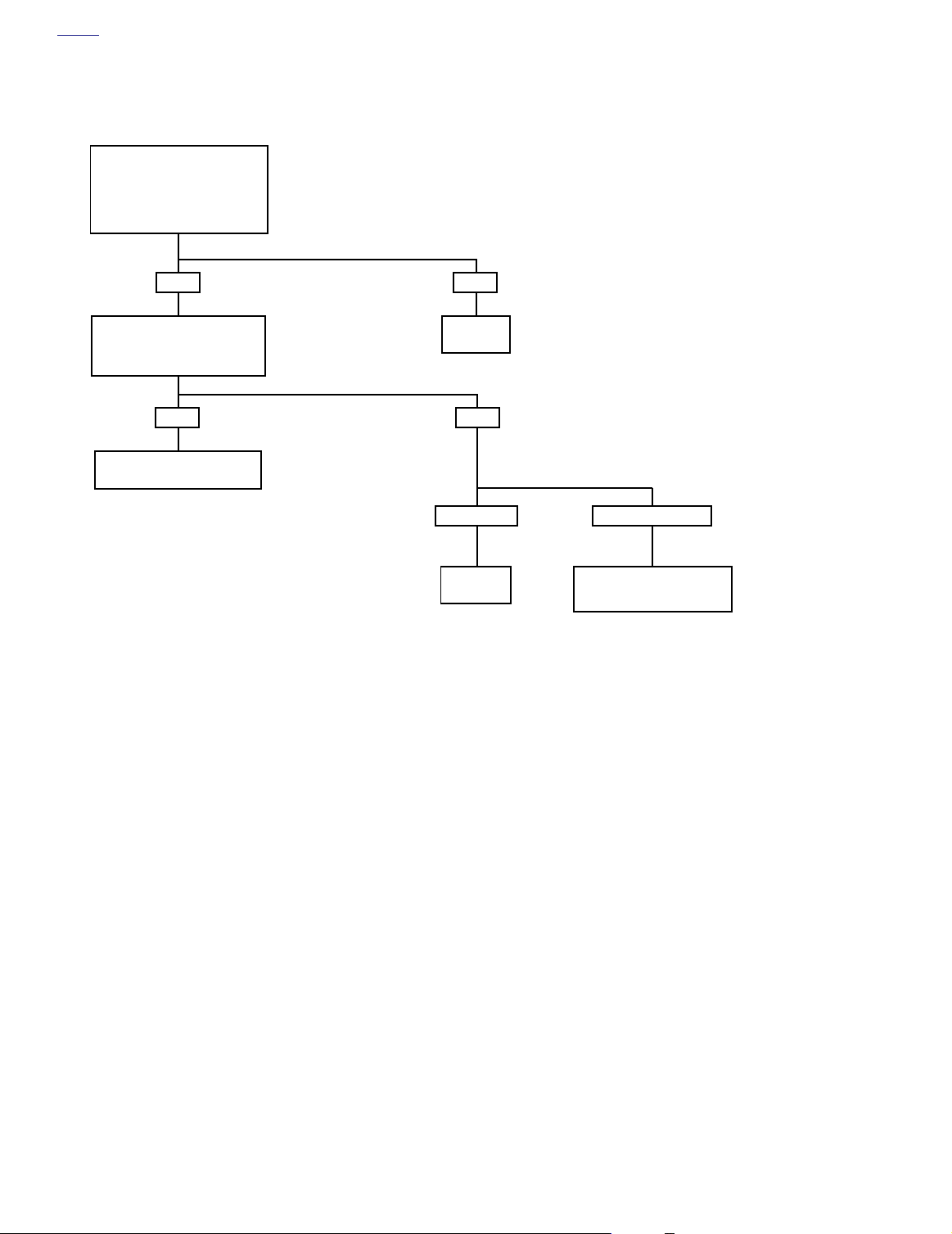
Turn Signal Error 2C
WILL NOT FLASH, 4-WAY FLASHERS INOPERABLE: DTC B1121, B1122, B1141
Continued from
Turn Signal Error 2A.
Check resistance to ground on
Pin 12 of connector [30].
Resistance less than 1 ohm?
YES
Check for 12 volts at both
terminals of 15 amp battery fuse.
Proper voltage present at
both terminals?
YES
Repair open in BN/GY wire
between battery fuse and TSSM.
NO
Repair poor
ground.
NO
1 Terminal.
Replace
fuse.
Neither terminal.
Repair open between 40 amp
maxi fuse and fuse block.
3-54 2004 Touring: TSM & TSSM
Page 13
HOME
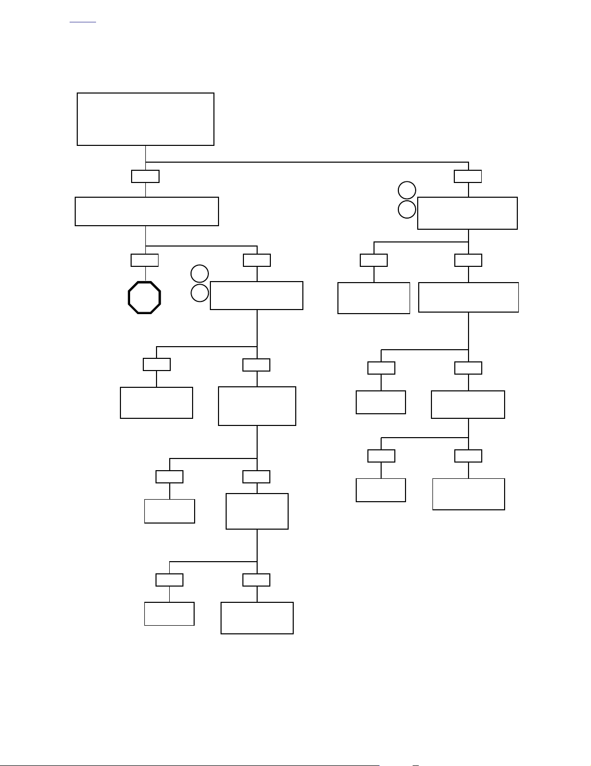
Turn Signal Error 2D
WILL NOT FLASH, 4-WAY FLASHERS INOPERABLE: DTC B1121, B1122, B1141
Continued from
Turn Signal Error 2A.
Check for 12 volts at Breakout Box terminal 7
(gray) with right turn button pressed.
Is proper voltage present?
YES
Check for 12 volts at Breakout Box
terminal 8 (gray) with left turn button pressed.
Is proper voltage present?
YES NO
6
STOP
Go to Turn Signal
Error 2B.
YES
Repair open
between connector
[24] and TSSM.
7
Is 12 volts present at Break-
out Box terminal 5 (gray)* with
left turn button pressed?
NO
Check for continuity to
ground at Breakout Box
terminal 5 (gray)*.
Is continuity present?
6
8
Box terminal 5 (black) with right
YES NO
Repair open
between connector
[22] and TSSM.
YES NO
Repair short
to ground.
YES NO
Check for continuity to ground at
Breakout Box terminal 5 (black).
NO
Is 12 volts present at Breakout
turn button pressed?
Is continuity present?
Is 12 volts present at
Breakout Box terminal
1 (black)?
YES
Repair short
to ground.
YES NO
Replace turn
signal switch.
Repair open between
NO
Is 12 volts present
at Breakout Box
terminal 1 (gray)*?
connector [24] and
fuse block.
Replace turn
signal switch.
Repair open between
connector [22] and
*Black on FLHR/C/S models
2004 Touring: TSM & TSSM 3-55
fuse block.
Page 14

HOME
Turn Signal Error 3A
FLASH AT DOUBLE NORMAL RATE, ALL BULBS WORKING
Determine correct part number for
all installed turn signal bulbs and verify
against parts installed on motorcycle.
Correct parts installed?
YES
Remove corrosion with a wire
brush. Install ELECTRICAL
CONTACT LUBRICANT (Part
No. 99861-02) in bulb sockets.
Do lamps flash at normal rate?
YES
System
OK.
NO
Clean or replace bulb.
Do lamps flash
at normal rate?
NOYES
YES
Check for corrosion
on bulbs and/or sockets.
9
Corrosion present?
NO
Check for corrosion
on all lamp connection
terminals. Corrosion present?
YES
Clean corrosion from
wires and terminals.
Do lamps flash at
normal rate?
YES
NO
Replace with
correct bulbs.
7
NO
Replace TSM/TSSM.
Learn password (if
needed) and perform
setup.
NO
System
OK.
3-56 2004 Touring: TSM & TSSM
Replace lamp
assembly.
System
OK.
Replace TSM/TSSM.
Learn password (if
needed) and perform
setup.
Page 15

HOME
DTC B0563 3.16
GENERAL
Battery Voltage High
The TSM/TSSM continually checks the battery voltage during
IGN/OFF and IGN/RUN power modes. If the voltage exceeds
16.0 volts for more than 5.0±0.5 seconds, the TSM/TSSM
sets diagnostic trouble code (DTC) B0563.
DIAGNOSTICS
Diagnostic Tips
●
This DTC may set when the vehicle is placed on a a battery charger, on fast charge, for a long period of time.
The TSSM does not illuminate the security lamp when
●
this code is set as current.
Diagnostic Notes
See 1.7 CHARGING SYSTEM tests in Section 1 to correct.
Problem may be faulty voltage regulator.
2004 Touring: TSM & TSSM 3-57
Page 16

HOME
DTC B1131, B1132 3.17
GENERAL
NOTE
This section applies only to those vehicles equipped with the
optional security system.
Alarm Output Low (DTC B1131) or Alarm Output High (DTC B1132)
See Figure 3-31. An alarm cycle is activated when the TSSM
is connected, the siren has been armed by the TSSM and a
security event occurs. See 3.6 SECURITY SYSTEM (TSSM)
FUNCTIONS. Under normal armed operation, the siren input
(terminal B) is driven low by the TSSM to trigger the audible
alarm. When the siren input is driven high by the TSSM the
audible alarm stops.
DIAGNOSTICS
Diagnostic Tips
●
If the siren is armed and the internal siren battery is
dead, shorted, disconnected, or has been charging for a
period longer than 24 hours, the siren will respond with
three chirps on arming instead of two.
The internal siren battery may not charge if the vehicle’s
●
battery is less than 12.5 volts.
●
If the siren does not chirp, two or three times, on a valid
arming command from the TSSM, the siren is either not
connected, not working, or the siren wiring was opened
or shorted while the siren was disarmed.
●
If the siren enters the self-driven mode where it is powered from the siren internal nine-volt battery, the turn-signal lamps will not alternately flash. If the TSSM activates
the siren, the turn-signal lamps will flash. If the siren has
been armed and a security event occurs, and the siren is
in self-driven mode, the siren will alarm for 20 to 30 seconds and then turn off for 5 to 10 seconds. This alarm
cycle will be repeated ten times if the siren is in the selfdriven mode.
●
If the siren does not stop alarming after it has been
armed, then either the TSSM output or siren input may
be shorted to ground, or the siren vehicle battery connection is open or shorted to ground, or the siren vehicle
ground connection is open, or a security event has
occurred. See 3.6 SECURITY SYSTEM (TSSM) FUNC-
TIONS for a description of alarm functions.
o0236xox
Figure 3-31. Siren
Diagnostic Notes
The reference numbers below correlate with the circled numbers on the Test 3.17 flow chart.
1. Use BREAKOUT BOX (Part No. HD-42682) and HARNESS CONNECTOR TEST KIT (Part No. HD-41404),
gray pin probe and patch cord. See 3.11 BREAKOUT
BOX: TSM/TSSM.
2. Use HARNESS CONNECTOR TEST KIT (Part No. HD-
41404), gray socket probe and patch cord.
3. Having the correct multimeter ohm scale is important for
this test. Some meters may read infinity for high ohm values. If this is the case, check your ohm scale and retest.
3-58 2004 Touring: TSM & TSSM
Page 17

HOME
f2208o8x
[142B][142A]
BK
Security
Siren
(Optional)
[33B][33A]
Ignition
Key Switch
R
R/BK
R
–+
Battery
A
B
C
40 Amp
Maxi Fuse
BN/GY
Lt GN/BN
BK
Sidecar
BAS
A B C
R
15 Amp
Battery
Fuse
[134B][134A]
BN/GY
GY
Signal
TN/GN
BK
Lt GN/BN
3216
[30B]
[30A]
54987121110
321654987121110
TSSM
Figure 3-32. Siren Circuit
Table 3-21. Wire Harness Connectors in Figure 3-32.
NO.
[30] TSM/TSSM 12-Place Deutsch
[134] Sidecar BAS 3-Place Packard Under Seat
[142] Siren 3-Place Packard Under Right Side Cover (Behind Electrical Bracket)
DESCRIPTION TYPE LOCATION
Cavity in Crossmember
at Rear of Battery Box (Under Seat)
2004 Touring: TSM & TSSM 3-59
Page 18

HOME
Test 3.17
ALARM OUTPUT: DTC B1131, B1132
Check for battery voltage at
siren sensor connector [142B]. With
ignition ON, measure voltage between
terminal C (BK) and terminal A (BN/GY).
Is battery voltage present?
YES
1
With ignition OFF, measure resistance
between siren connector [142B] Terminal B
and Breakout Box cavity 11 (gray).
Is resistance less than 1 ohm?
YES
Measure resistance between Breakout
Box cavity 11 and chassis ground.
Is resistance less than 1 ohm?
YES
Locate and repair
grounded Lt GN/BN wire.
NO
Locate and repair
open on Lt GN/BN wire.
2
NO
3
Disconnect siren from Breakout Box.
Measure resistance between siren
connector [142A] Terminal B and C.
is resistance between 120,000-200,000
ohms with siren disconnected?
1
With ignition OFF, check continuity between
continuity between siren connector [142B]
YES
Locate and repair
short between BN/GY
and BK wires.
NO
siren connector [142B] Terminal C and
Breakout Box cavity 12. Then measure
Terminal A and Breakout Box cavity 1.
Is continuity present?
NO
Repair
open wire.
3-60 2004 Touring: TSM & TSSM
YES
Connect siren to a known good
motorcycle. Arm and activate siren
to verify operation. Disarm siren.
Did siren operate correctly?
YES NO
Replace TSSM. Learn
password and perform
setup.
Clear codes using speedometer self diagnostics.
See 3.10 SPEEDOMETER SELF DIAGNOSTICS.
Confirm proper operation with no check engine
lamp.
NO
Replace
siren.
Replace
siren.
Page 19

FLHR/C/S
f2210x8x
Starter
Relay [123]
Brake Light
Relay [124]
f2192x8x
NOTE
Check the wire tags for positive
identification of relays. Starter
relay can be positively identified
by heavy gauge Green wire.
FLTR, FLHT/C/U
Starter
Relay [123]
Ignition Keyswitch
Relay [126]
HOME
DTC B1134 3.18
GENERAL
Starter Output High
With the TSM/TSSM disarmed, ignition ON and RUN/STOP
switch set to RUN the starter relay is grounded. Battery voltage is applied to the starter relay and coil which are grounded
through the TSM/TSSM. This code is set when that ground is
not established through the TSM/TSSM.
DIAGNOSTICS
Diagnostic Notes
The reference numbers below correlate with the circled numbers on the Test 3.18 flow charts.
1. Connect BREAKOUT BOX (Part No. HD-42682) (gray) to
wire harness connector [30] leaving TSM/TSSM disconnected. See 3.11 BREAKOUT BOX: TSM/TSSM.
Figure 3-33. Locate Starter Relay
2004 Touring: TSM & TSSM 3-61
Page 20

HOME
f2208p8x
Ignition
Switch
[33A]
[33B]
BK
Starter Relay
TN/GN
30 85 86
87A
KTESU
87
[62B]
R
–+
Battery
BK/R
R/GY
To Right Handlebar
Switch [22]
40 Amp
Maxi Fuse
R
R
R/GY
15 Amp
Battery
Fuse
[30B]
[30A]
BN/GY
321654987121110
321654987121110
TSSM
TN/GN
BK
Figure 3-34. Starter/TSSM Circuit
Table 3-22. Wire Harness Connectors in Figure 3-34.
NO.
[30] TSSM All 12-Place Deutsch
[62] Starter Relay
3-62 2004 Touring: TSM & TSSM
DESCRIPTION MODEL TYPE LOCATION
FLHR/C/S Fuse Block Fuse Block (Under Left Side Cover)
FLTR, FLHT/C/U Relay Connector Rear of Battery Box - Left Side (Under Seat)
Cavity in Crossmember
at Rear of Battery Box (Under Seat)
Page 21

HOME
Test 3.18
STARTER OUTPUT HIGH: DTC B1134
1
Remove starter relay.
Check for voltage on
Breakout Box terminal 9 (gray).
Voltage present?
Locate and repair
short to voltage
on TN/GN wire.
NOYES
Install starter relay.
Is voltage present on
Breakout Box
terminal 9 (gray)?
YES
Replace
starter relay.
Clear codes using speedometer self diagnostics.
See 3.10 SPEEDOMETER SELF DIAGNOSTICS.
Confirm proper operation with no check engine
lamp.
Replace TSM/TSSM.
Learn password and
NO
perform setup.
2004 Touring: TSM & TSSM 3-63
Page 22

HOME
DTC B1135 3.19
GENERAL
Accelerometer Fault
This diagnostic trouble code (DTC) indicates a failure which
requires replacement of the TSM/TSSM.
NOTE
When DTC B1135 is set, the tip-over engine shutdown,
TSSM tamper alarm and bank angle sensors are disabled.
The security lamp will also illuminate on vehicles with security
systems.
3-64 2004 Touring: TSM & TSSM
Page 23

HOME
f2001x8x
f1998x9x
DTC B1151, B1152, B1153 3.20
GENERAL
Sidecar BAS Low (DTC B1151), High (DTC B1152) or Out of Range (DTC B1153)
These codes are set when a TSM/TSSM is configured for
sidecar use and a fault is detected with the sidecar BAS.
Table 3-23. Models Affected
VEHICLE
SECURITY
NO SECURITY
EFI CARBURETOR
Yes Yes
Yes Yes
DIAGNOSTICS
Diagnostic Tips
The smart siren cannot be disarmed when the ignition
●
switch is on and a bank angle sensor is installed. If the
ignition switch triggers the security alarm, then the switch
must be turned off to disarm the siren.
●
Use DIGITAL TECHNICIAN (Part No. HD-44750) to
ensure sidecar learn.
Ensure that no other circuits are tied to Pin 11 of the
●
TSSM.
If a sidecar is installed without the bank angle sensor kit
●
then the TSM/TSSM will continue to operate in Solo
mode on a sidecar bike.
●
If the bank angle sensor is removed without disabling
sidecar learning then the TSSM will set a DTC until sidecar learning is disabled using Digital Technician or the
bank angle sensor is reinstalled.
●
The software is designed to prevent the TSM/TSSM from
switching to sidecar mode unless the entire system is
operating properly (no codes set).
The bank angle sensor cannot be detected when the
●
security function is in the alarm mode (that is, lights
flashing, siren sounding).
●
A sidecar tip-over event cannot be detected when the
security function is in the alarm mode (that is, lights
flashing, siren sounding).
A short to ground fault cannot be detected when the
●
security function is in the alarm mode (that is, lights
flashing, siren sounding).
●
A short to battery fault cannot be detected
security function is in the alarm mode (that is, lights
flashing, siren sounding).
unless
the
Figure 3-35. Breakout Box (Part No. HD-42682)
Figure 3-36. Harness Connector Test Kit
(Part No. HD-41404
An out of range fault cannot be detected when the secu-
●
rity function is in the alarm mode (that is, lights flashing,
siren sounding).
)
Diagnostic Notes
The reference numbers below correlate with the circled numbers on the Test 3.17 flow chart.
1. Use BREAKOUT BOX (Part No. HD-42682) and HARNESS CONNECTOR TEST KIT (Part No. HD-41404),
gray pin probe and patch cord. See Section 3.11 BREA-
KOUT BOX: TSM/TSSM. See Figure 3-36.
2. Use HARNESS CONNECTOR TEST KIT (Part No. HD-
41404), gray pin probe and patch cord.
2004 Touring: TSM & TSSM 3-65
Page 24

HOME
f2208o8x
[142B][142A]
BK
Security
Siren
(Optional)
[33B][33A]
Ignition
Key Switch
R
R/BK
R
–+
Battery
A
B
C
40 Amp
Maxi Fuse
BN/GY
Lt GN/BN
BK
Sidecar
BAS
A B C
R
15 Amp
Battery
Fuse
[134B][134A]
BN/GY
GY
Signal
TN/GN
BK
Lt GN/BN
3216
[30B]
[30A]
54987121110
321654987121110
TSSM
Figure 3-37. Siren Circuit
Table 3-24. Wire Harness Connectors in Figure 3-32.
NO.
[30] TSM/TSSM 12-Place Deutsch
[134] Sidecar BAS 3-Place Packard Under Seat
[142] Siren 3-Place Packard Under Right Side Cover (Behind Electrical Bracket)
DESCRIPTION TYPE LOCATION
Cavity in Crossmember
at Rear of Battery Box (Under Seat)
3-66 2004 Touring: TSM & TSSM
Page 25

HOME
Test 3.20
SIDECAR BAS: DTC B1151, B1152, B1153
Disarm security system. Connect
Breakout Box to Connector [30]. Measure
1
voltage between Pins 2 (gray) and 12
(gray). Battery voltage present?
YES
With ignition OFF, check continuity
between Connector [134B]
Terminal C and Breakout Box
Pin 2 (gray). Then measure
continuity between Connector
[134B] Terminal A and Breakout
2
2
Box Pin 11 (gray).
Continuity present?
YES NO
Measure resistance
between Connector [134B]
Terminal B and Breakout Box
Pin 9 (gray).
Resistance less than 1 ohm?
YES
Jumper Pins 9 (gray) and 12 (gray)
on Breakout Box and then check
voltage on Pin 11 (gray).
Voltage Condition
< 0.25
> 8.0 Short to VBAT Yes
> 5.5 Disabled No
0.25-1.5 RUN No
Replace Sidecar BAS if voltage
Short to
Ground
is out of RUN range.
Codes
Set
Yes
Locate and repair
open wire.
NO
Locate and repair
open on TN/GN wire.
NO
See Will Not Flash, 4-Way
Flashers Inoperative.
Clear codes using speedometer self diagnostics.
See 3.10 SPEEDOMETER SELF DIAGNOSTICS.
Confirm proper operation with no check engine
lamp.
2004 Touring: TSM & TSSM 3-67
Page 26

HOME
DTC U1016, U1255 3.21
GENERAL
Loss of ICM/ECM Serial Data
The serial data connector provides a means for the ignition
control module (ICM) or electronic control module (ECM),
TSM/TSSM and speedometer to communicate their current
status. When all operating parameters on the serial data bus
are within specifications, a state of health message is sent
between the components. A diagnostic trouble code (DTC)
U1016 indicates that the ICM/ECM is not capable of sending
this state of health message.
Table 3-25. Code Description
DTC DESCRIPTION
Loss of all ECM serial data
(state of health)
U1016
U1255 Serial data error/missing message
Loss of vehicle speed
Loss of vehicle inhibit motion
Loss of powertrain security status
Carbureted
f1917x9x
f2191x8x
Ignition Control Module
Connector [10]
DIAGNOSTICS
Diagnostic Notes
The reference numbers below correlate with the circled numbers on the Test 3.21 flow chart.
1. Connect BREAKOUT BOX (Part No. HD-42682) (gray)
between TSM?TSSM connector [30A] and wire harness
connector [30B]. See 3.11 BREAKOUT BOX: TSM/
TSSM.
6924
4
3
1. Terminal 1: flash pin-EFI models (Lt GN/R)
2. Terminal 2: ground (BK)
3. Terminal 3: serial data (Lt GN/V)
4. Terminal 4: power (GY)
5. Protective cap
1
5
2
Fuel Injected
Figure 3-39. Electrical Bracket (Under Right Side Cover)
2. Connect BREAKOUT BOX (Part No. HD-42682) (black)
between ICM connector [10A] and wiring harness connector [10B]. See 4.6 BREAKOUT BOX: ICM
3. Connect BREAKOUT BOX (Part No. HD-43876)
between wire harness and ECM. See 5.7 BREAKOUT
BOX: EFI.
Electronic Control
Module Connector [78]
Figure 3-38. Data Link Connector
3-68 2004 Touring: TSM & TSSM
Page 27

HOME
[2A]
[2B]
f2208z8x
321654987121110
321654987121110
Speedometer
15A
Accessory
Fuse
321654987121110
321654987121110
Main to Interconnect
Harness
BK
LtGN/V
O
BN/GY
[39B]
[39A]
[108B]
[108A]
321654987121110
321654987121110
Tachometer
[1B] [1A]
123
123
Main to Interconnect
Harness
6
6
101112 78945
101112 78945
[156B] [156A]
6
6
5
5
4
4
3
3
2
2
1
1
BN/GY
Main to Interconnect
Harness
LtGN/V
GY
65
4
32
1
1
15A
Ignition
Fuse
6
5
4
32
GY
987
987
321654987121110
321654987121110
TSM/TSSM
BK
[8B]
121110
121110
[8A]
Ignition
Harness
1
2
3
4
Data Link
[91A]
BK
[30B]
[30A]
LtGN/V
15A
Battery
Fuse
[10B]
[10A]
Ignition Control Module
12
12
Serial data
Figure 3-40. Serial Data Circuit: FLHT/C (Carbureted)
Table 3-26. Wire Harness Connectors in Figure 3-40.
NO. DESCRIPTION TYPE LOCATION
[1] Main to Interconnect Harness 12-Place Deutsch (Black) Inner Fairing - Right Radio Support Bracket
[2] Main to Interconnect Harness 12-Place Deutsch (Gray) Inner Fairing - Right Fairing Support Brace
[8] Ignition Harness 12-Place Deutsch Under Right Side Cover
[10] Ignition Control Module 12-Place Deutsch Under Right Side Cover
[30] Turn Signal/Security Module 12-Place Deutsch
[39] Speedometer 12-Place Packard Inner Fairing (Back of Speedometer)
[91] Data Link 4-Place Deutsch Under Right Side Cover
[108] Tachometer 12-Place Packard Inner Fairing (Back of Tachometer)
[156] Main to Interconnect Harness 6-Place Deutsch Inner Fairing - Right Fairing Support Brace
Cavity in Crossmember at Rear of
Battery Box (Under Seat)
2004 Touring: TSM & TSSM 3-69
Page 28

HOME
f2208y8x
BN/GY
BK
321654987121110
321654987121110
15A
Battery
Fuse
Speedometer
LtGN/V
BN/GY
O
15A
Accessory
Fuse
[39B]
[39A]
15A
Ignition
Fuse
LtGN/V
GY
21
21
GY
BK
321654987121110
321654987121110
[30B]
[30A]
TSM/TSSM
BK
[8B]
[8A]
[91A]
Ignition
Harness
1
2
3
4
Data Link
987
6
54
3
98
7
654
3
121110
121110
LtGN/V
[10B]
[10A]
Ignition Control Module
12
12
Serial data
Figure 3-41. Serial Data Circuit: FLHR/S (Carbureted)
Table 3-27. Wire Harness Connectors in Figure 3-41.
NO.
[8] Ignition Harness 12-Place Deutsch Under Right Side Cover
[10] Ignition Control Module 12-Place Deutsch Under Right Side Cover
[30] Turn Signal/Security Module 12-Place Deutsch
[39] Speedometer 12-Place Packard Under Console (Back of Speedometer)
[91] Data Link 4-Place Deutsch Under Right Side Cover
DESCRIPTION TYPE LOCATION
Cavity in Crossmember at Rear of
Battery Box (Under Seat)
3-70 2004 Touring: TSM & TSSM
Page 29

HOME
f2208u8x
321654987121110
321654987121110
Speedometer
BK
LtGN/V
O
BN/GY
[39B]
[108B]
[108A]
[39A]
BN/GY
321654987121110
321654987121110
Tachometer
[156B] [156A]
6
6
5
5
4
4
3
3
2
2
1
1
Main to Interconnect
Harness
LtGN/V
GY
65
4
32
1
1
65
4
32
GY
987
987
321654987121110
321654987121110
TSM/TSSM
BK
[8B]
121110
121110
[8A]
Ignition
Harness
BK
[30B]
[30A]
[1B] [1A]
123
123
Main to Interconnect
Harness
6
6
15A
Ignition
Fuse
1
2
3
4
Data Link
[91A]
[2B]
[2A]
15A
Accessory
Fuse
321654987121110
321654987121110
Main to Interconnect
Harness
101112 78945
101112 78945
LtGN/V
15A
Battery
Fuse
LtGN/R
51
Flash pin
ECM
Serial data
[78B]
[78A]
Figure 3-42. Serial Data Circuit: FLTR, FLHT/C/U (Fuel Injected)
Table 3-28. Wire Harness Connectors in Figure 3-42.
NO.
[1]
[2]
[8] Ignition Harness All 12-Place Deutsch Under Right Side Cover
[10] Ignition Control Module All 12-Place Deutsch Under Right Side Cover
[30]
[39] Speedometer
[91] Data Link All 4-Place Deutsch Under Right Side Cover
[108] Tachometer
[156]
DESCRIPTION MODEL TYPE LOCATION
Main to Interconnect
Harness
Main to Interconnect
Harness
Tu rn Signal/Security
Module
FLHT/C 12-Place Deutsch (Black) Inner Fairing - Right Radio Support Bracket
FLTR 12-Place Deutsch (Black) Inner Fairing - Below Radio (Left Side)
FLHT/C 12-Place Deutsch (Gray) Inner Fairing - Right Fairing Support Brace
FLTR 12-Place Deutsch (Gray) Inner Fairing - Below Radio (Left Side)
All 12-Place Deutsch
Cavity in Crossmember at Rear of
Battery Box (Under Seat)
FLHT/C 12-Place Packard Inner Fairing (Back of Speedometer)
FLTR 12-Place Packard Under Bezel (Back of Speedometer)
FLHT/C 12-Place Packard Inner Fairing (Back of Tachometer)
FLTR 12-Place Packard Under Bezel (Back of Tachometer)
Main to Interconnect
Harness
FLHT/C 6-Place Deutsch Inner Fairing - Right Fairing Support Brace
FLTR 6-Place Deutsch Inner Fairing - Front of Right Fairing Bracket
2004 Touring: TSM & TSSM 3-71
Page 30

HOME
f2208t8x
BN/GY
321654987121110
321654987121110
Speedometer
15A
Battery
Fuse
BK
15A
Accessory
Fuse
LtGN/V
BN/GY
O
[39B]
[39A]
15A
Ignition
Fuse
LtGN/V
GY
3
21
321
GY
BK
321654987121110
321654987121110
[30B]
[30A]
TSM/TSSM
BK
98
7
65
4
98
7
65
4
121110
[8B]
Ignition
[8A]
Harness
121110
1
2
3
4
Data Link
[91A]
LtGN/V
LtGN/R
[78B]
[78A]
1
Flash pin
5
Serial data
ECM
Figure 3-43. Serial Data Circuit: FLHR/C/S (Fuel Injected)
Table 3-29. Wire Harness Connectors in Figure 3-43.
NO.
[8] Ignition Harness 12-Place Deutsch Under Right Side Cover
[10] Ignition Control Module 12-Place Deutsch Under Right Side Cover
[30] Turn Signal/Security Module 12-Place Deutsch
[39] Speedometer 12-Place Packard Under Console (Back of Speedometer)
[78] Electronic Control Module 36-Place Packard Under Right Side Cover
[91] Data Link 4-Place Deutsch Under Right Side Cover
DESCRIPTION TYPE LOCATION
Cavity in Crossmember at Rear of
Battery Box (Under Seat)
3-72 2004 Touring: TSM & TSSM
Page 31

HOME
Test 3.21
LOSS OF ICM/ECM SERIAL DATA: DTC U1016
Can you read ECM/ICM hardware P/N?
See 3.10 SPEEDOMETER SELF DIAGNOSTICS.
Install Breakout Box on TSM/TSSM.
1
CARBURETED
2
MODELS
While wiggling harness, check
continuity between breakout box
terminal 3 (gray) and breakout
box terminal 12 (black).
Continuity present?
YES
EFI MODELS
3
While wiggling harness, check conti-
nuity between terminal 3 (gray) of
TSM/TSSM breakout box and termi-
nal 5 of ECM Breakout Box.
Continuity present?
1
CARBURETED
2
MODELS
Check continuity between
breakout box terminal 3
(gray) and breakout box
terminal 12 (black).
Continuity present?
YES
Replace ICM.
Reprogram and learn
password.
NO or “No Rsp”
Install Breakout Box on TSM/TSSM.
EFI MODELS
3
Check continuity between termi-
Check continuity between termi-
nal 2 (black) of speedometer
nal 3 (gray) of TSM/TSSM break-
Breakout Box and terminal 5 of
out box and terminal 5 of ECM
ECM Breakout Box.
breakout box.
Continuity present?
Continuity present?
NO
Repair open on
LtGN/V wire.
Reprogram and learn
YES
Replace ECM.
password.
YES
Clear codes. Test ride.
Does DTC U1016
return?
YES
Replace ICM.
Reprogram and learn
password.
NO
Repair intermittent
on Lt GN/V wire.
NO
No trouble found.
YES
Clear codes. Test ride. Did DTC
U1016 return?
YES NO
Replace ECM.
Reprogram and learn
password.
No trouble found.
Clear codes using speedometer self diagnostics.
See 3.10 SPEEDOMETER SELF DIAGNOSTICS.
Confirm proper operation with no check engine
lamp.
2004 Touring: TSM & TSSM 3-73
Page 32

HOME
DTC U1097, U1255 3.22
GENERAL
Loss of Speedometer Serial Data
The serial data line provides a means for the speedometer,
ICM/ECM and TSM/TSSM to communicate their current status. When all operating parameters are within specifications,
a state of health message is sent between the components. A
DTC U1097 indicates that the speedometer is not capable of
sending this state of health message.
Table 3-30. Code Description
DTC
U1097
U1255 Serial data error/missing message
Loss of all speedometer serial data
(state of health)
DESCRIPTION
DIAGNOSTICS
Diagnostic Notes
The reference numbers below correlate with the circled numbers on the test 3.22 flow chart.
1. For carbureted models, connect BREAKOUT BOX (Part
No. HD-42682) between wire harness and ICM. See 4.6
BREAKOUT BOX: ICM. For EFI models, connect BREA-
KOUT BOX (Part No. HD-43876) between wire harness
and ECM. See 5.7 BREAKOUT BOX: EFI.
2. Connect BREAKOUT BOX (Part No. HD-42682) (black)
as follows:
6924
4
1
5
Carbureted
f1917x9x
f2191x8x
Ignition Control Module
Connector [10]
3
2
1. Terminal 1: flash pin-EFI models (Lt GN/R)
2. Terminal 2: ground (BK)
3. Terminal 3: serial data (Lt GN/V)
4. Terminal 4: power (GY)
5. Protective cap
Figure 3-44. Data Link Connector
3-74 2004 Touring: TSM & TSSM
Fuel Injected
Figure 3-45. Electrical Bracket (Under Right Side Cover)
a. Mate black socket housing on Breakout Box with
speedometer connector [39A] (at the back of the
speedometer) using INSTRUMENT HARNESS
ADAPTERS (Part No.HD-46601).
b. Mate black pin housing on Breakout Box with wire
harness connector [39B] using INSTRUMENT HARNESS ADAPTERS (Part No.HD-46601).
Electronic Control
Module Connector [78]
Page 33

HOME
[2A]
[2B]
f2208z8x
321654987121110
321654987121110
Speedometer
15A
Accessory
Fuse
321654987121110
321654987121110
Main to Interconnect
Harness
BK
LtGN/V
O
BN/GY
[39B]
[39A]
[108B]
[108A]
321654987121110
321654987121110
Tachometer
[1B] [1A]
123
123
Main to Interconnect
Harness
6
6
101112 78945
101112 78945
[156B] [156A]
6
6
5
5
4
4
3
3
2
2
1
1
BN/GY
Main to Interconnect
Harness
LtGN/V
GY
65
4
32
1
1
15A
Ignition
Fuse
6
5
4
32
GY
987
987
321654987121110
321654987121110
TSM/TSSM
BK
[8B]
121110
121110
[8A]
Ignition
Harness
1
2
3
4
Data Link
[91A]
BK
[30B]
[30A]
LtGN/V
15A
Battery
Fuse
[10B]
[10A]
Ignition Control Module
12
12
Serial data
Figure 3-46. Serial Data Circuit: FLHT/C (Carbureted)
Table 3-31. Wire Harness Connectors in Figure 3-46.
NO. DESCRIPTION TYPE LOCATION
[1] Main to Interconnect Harness 12-Place Deutsch (Black) Inner Fairing - Right Radio Support Bracket
[2] Main to Interconnect Harness 12-Place Deutsch (Gray) Inner Fairing - Right Fairing Support Brace
[8] Ignition Harness 12-Place Deutsch Under Right Side Cover
[10] Ignition Control Module 12-Place Deutsch Under Right Side Cover
[30] Turn Signal/Security Module 12-Place Deutsch
[39] Speedometer 12-Place Packard Inner Fairing (Back of Speedometer)
[91] Data Link 4-Place Deutsch Under Right Side Cover
[108] Tachometer 12-Place Packard Inner Fairing (Back of Tachometer)
[156] Main to Interconnect Harness 6-Place Deutsch Inner Fairing - Right Fairing Support Brace
Cavity in Crossmember at Rear of
Battery Box (Under Seat)
2004 Touring: TSM & TSSM 3-75
Page 34

HOME
f2208y8x
BN/GY
BK
321654987121110
321654987121110
15A
Battery
Fuse
Speedometer
LtGN/V
BN/GY
O
15A
Accessory
Fuse
[39B]
[39A]
15A
Ignition
Fuse
LtGN/V
GY
21
21
GY
BK
321654987121110
321654987121110
[30B]
[30A]
TSM/TSSM
BK
[8B]
[8A]
[91A]
Ignition
Harness
1
2
3
4
Data Link
987
6
54
3
98
7
654
3
121110
121110
LtGN/V
[10B]
[10A]
Ignition Control Module
12
12
Serial data
Figure 3-47. Serial Data Circuit: FLHR/S (Carbureted)
Table 3-32. Wire Harness Connectors in Figure 3-47.
NO. DESCRIPTION TYPE LOCATION
[8] Ignition Harness 12-Place Deutsch Under Right Side Cover
[10] Ignition Control Module 12-Place Deutsch Under Right Side Cover
[30] Turn Signal/Security Module 12-Place Deutsch
[39] Speedometer 12-Place Packard Under Console (Back of Speedometer)
[91] Data Link 4-Place Deutsch Under Right Side Cover
Cavity in Crossmember at Rear of
Battery Box (Under Seat)
3-76 2004 Touring: TSM & TSSM
Page 35

HOME
f2208u8x
321654987121110
321654987121110
Speedometer
BK
LtGN/V
O
BN/GY
[39B]
[108B]
[108A]
[39A]
BN/GY
321654987121110
321654987121110
Tachometer
[156B] [156A]
6
6
5
5
4
4
3
3
2
2
1
1
Main to Interconnect
Harness
LtGN/V
GY
65
4
32
1
1
65
4
32
GY
987
987
321654987121110
321654987121110
TSM/TSSM
BK
[8B]
121110
121110
[8A]
Ignition
Harness
BK
[30B]
[30A]
[1B] [1A]
123
123
Main to Interconnect
Harness
6
6
15A
Ignition
Fuse
1
2
3
4
Data Link
[91A]
[2B]
[2A]
15A
Accessory
Fuse
321654987121110
321654987121110
Main to Interconnect
Harness
101112 78945
101112 78945
LtGN/V
15A
Battery
Fuse
LtGN/R
51
Flash pin
ECM
Serial data
[78B]
[78A]
Figure 3-48. Serial Data Circuit: FLTR, FLHT/C/U (Fuel Injected)
Table 3-33. Wire Harness Connectors in Figure 3-48.
NO. DESCRIPTION MODEL TYPE LOCATION
Main to Interconnect
[1]
Harness
Main to Interconnect
[2]
Harness
[8] Ignition Harness All 12-Place Deutsch Under Right Side Cover
[10] Ignition Control Module All 12-Place Deutsch Under Right Side Cover
[30]
Tu rn Signal/Security
Module
[39] Speedometer
[91] Data Link All 4-Place Deutsch Under Right Side Cover
[108] Tachometer
[156]
Main to Interconnect
Harness
FLHT/C 12-Place Deutsch (Black) Inner Fairing - Right Radio Support Bracket
FLTR 12-Place Deutsch (Black) Inner Fairing - Below Radio (Left Side)
FLHT/C 12-Place Deutsch (Gray) Inner Fairing - Right Fairing Support Brace
FLTR 12-Place Deutsch (Gray) Inner Fairing - Below Radio (Left Side)
All 12-Place Deutsch
Cavity in Crossmember at Rear of
Battery Box (Under Seat)
FLHT/C 12-Place Packard Inner Fairing (Back of Speedometer)
FLTR 12-Place Packard Under Bezel (Back of Speedometer)
FLHT/C 12-Place Packard Inner Fairing (Back of Tachometer)
FLTR 12-Place Packard Under Bezel (Back of Tachometer)
FLHT/C 6-Place Deutsch Inner Fairing - Right Fairing Support Brace
FLTR 6-Place Deutsch Inner Fairing - Front of Right Fairing Bracket
2004 Touring: TSM & TSSM 3-77
Page 36

HOME
f2208t8x
BN/GY
321654987121110
321654987121110
Speedometer
15A
Battery
Fuse
BK
15A
Accessory
Fuse
LtGN/V
BN/GY
O
[39B]
[39A]
15A
Ignition
Fuse
LtGN/V
GY
3
21
321
GY
BK
321654987121110
321654987121110
[30B]
[30A]
TSM/TSSM
BK
98
7
65
4
98
7
65
4
121110
[8B]
Ignition
[8A]
Harness
121110
1
2
3
4
Data Link
[91A]
LtGN/V
LtGN/R
[78B]
[78A]
1
Flash pin
5
Serial data
ECM
Figure 3-49. Serial Data Circuit: FLHR/C/S (Fuel Injected)
Table 3-34. Wire Harness Connectors in Figure 3-49.
NO. DESCRIPTION TYPE LOCATION
[8] Ignition Harness 12-Place Deutsch Under Right Side Cover
[10] Ignition Control Module 12-Place Deutsch Under Right Side Cover
[30] Turn Signal/Security Module 12-Place Deutsch
[39] Speedometer 12-Place Packard Under Console (Back of Speedometer)
[78] Electronic Control Module 36-Place Packard Under Right Side Cover
[91] Data Link 4-Place Deutsch Under Right Side Cover
Cavity in Crossmember at Rear of
Battery Box (Under Seat)
3-78 2004 Touring: TSM & TSSM
Page 37

HOME
Test 3.22
LOSS OF SPEEDOMETER SERIAL DATA: DTC
U1097, U1255
Can you read TSM/TSSM hardware P/N?
See 3.10 SPEEDOMETER SELF DIAGNOSTICS
1
YES
While wiggling harness, check for
continuity between Breakout Box
terminal 3 (gray) and terminal 2 (black).
Is continuity present?
Clear DTCs. Test Ride.
Did DTC U1097 return?
YES
Replace speedometer.
NOYES
Repair intermittent on
Lt GN/V wire.
NO
No trouble found
NO or “No rsp”
1
Check for continuity between
Breakout Box terminal 3 (gray)
and terminal 2 (black).
Is continuity present?
YES NO
Replace speedometer.
Clear codes using speedometer self diagnostics.
See 3.10 SPEEDOMETER SELF DIAGNOSTICS.
Confirm proper operation with no check engine
lamp.
Repair open on
Lt GN/V wire.
2004 Touring: TSM & TSSM 3-79
Page 38

HOME
DTC U1300, U1301 OR “BUS ER” 3.23
GENERAL
Serial Data Low or Serial data Open/High
See Figure 3-50. The typical serial data voltage range is 0
volts (inactive) to 7 volts (active). Due to the short pulse, voltages will be much lower on a DVOM. In analog mode, a
DVOM reading serial data will show continuous voltage when
active, typically 0.6-0.8 volts. The range for acceptable operations is 0-7.0 volts.
Table 2-35. Code Description
DTC DESCRIPTION
U1300 Serial data low
U1301 Serial data open/high
DIAGNOSTICS
Diagnostic Tips
● If serial data is shorted, these diagnostic trouble codes
(DTCs) will automatically cause the check engine lamp
to illuminate. The odometer will read “Bus Er” in this condition.
● Diagnostic trouble codes (DTCs) P1009 and P1010 may
accompany DTCs U1300 and U1301.
Diagnostic Notes
● If a U1300, U1301 or “BUS Er” is present on carbureted
models, perform diagnostic procedures listed in 4.10
STARTS, THEN STALLS.
● If a U1300, U1301 or “BUS Er” is present on EFI models,
perform diagnostic procedures listed in 5.12 STARTS,
THEN STALLS.
f2191x8x
Data Link
Carbureted
f1917x9x
Fuel Injected
Figure 3-50. Electrical Bracket (Under Right Side Cover)
Connector [91]
Data Link
Connector [91]
3-80 2004 Touring: TSM & TSSM
Page 39

HOME
PASSWORD LEARN 3.24
GENERAL
If the ECM/ICM or TSM/TSSM is faulty, follow the instructions
in the Touring Service Manual for ECM/ICM or TSM/TSSM
replacement. Then, to determine if password learn is necessary, refer to Ta bl e 3-36.
Table 3-36. Password Learn
DEVICE REPLACED
ECM Yes
ICM Yes
TSM No*
TSSM Yes
*If a TSM has been replaced by a TSSM, or a TSSM has
been replaced by a TSM, password learn is necessary.
IS PASSWORD LEARN
NECESSARY
PASSWORD LEARNING
To perform password learning procedure, refer to Ta bl e 3-37.
When finished, continue with all instructions under 3.3 TSM/
TSSM VEHICLE DELIVERY.
Always perform all appropriate instructions under 3.3 TSM/
TSSM VEHICLE DELIVERY after TSM/TSSM replacement or
removal.
IMPORTANT NOTE
Do not forget to enter a personal code for TSSM vehicles.
If a code is not assigned and both key fobs are lost or
damaged while the vehicle is armed, the TSSM must be
replaced.
2004 Touring: TSM & TSSM 3-81
Page 40

HOME
Table 3-37. Setting TSM/TSSM and ECM/ICM Password
NO. ACTION CONFIRMATION NOTES
Ignition must be turned off for at least 15
seconds.
Install new TSM/TSSM or ECM/ICM.
1
Perform all steps under 3.3 TSM/TSSM
VEHICLE DELIVERY.
2 Set RUN/OFF switch to RUN.
3Turn IGN key ON.
4Attempt normal start one time.
Wait ten seconds. Security lamp will illu-
5
minate and stay on.
6 Wait until Security Lamp turns off. This takes ten minutes.
Quickly (within two seconds) turn IGN
7
key OFF-ON.
8Wait until Security Lamp turns off. This takes ten minutes.
Quickly (within two seconds) turn IGN
9
key OFF-ON.
10 Wait until Security Lamp turns off. This takes ten minutes.
Quickly (within two seconds) turn IGN
11
key OFF-ON.
Tu r n IGN key OFF. Wait 15 seconds
before turning IGN on. Tu r n IGN switch
ON and start engine to confirm success-
12
ful Password Learn procedure. Clear
trouble codes.
Perform all steps under 3.3 TSM/TSSM
13
VEHICLE DELIVERY.
With ignition turned off, Check Engine
Lamp and Security Lamp will be off.
Verify Check Engine Lamp and Security
Lamp illuminate and then turn off.
Carbureted models: Engine starts and
stalls. Check Engine Lamp performs 4
seconds on, 4 seconds off, 8 seconds on,
off sequence.
EFI models: Engine starts and stalls.
Check Engine Lamp illuminates and
stays on.
Security Lamp illuminates.
TSM/TSSM enables starter
relay.
Password has not been
learned. ECM/ICM sets DTC
P1009.
ECM/ICM enters Password
Learning mode for ten minutes. Do not cycle ignition
switch or interrupt vehicle
power or Password Learn will
be unsuccessful.
ECM/ICM must not be
allowed to shutdown.
ECM/ICM must not be
allowed to shutdown.
ECM/ICM must not be
allowed to shutdown.
3-82 2004 Touring: TSM & TSSM
Page 41

HOME
1. Battery
2. Battery contact
3. Circuit board
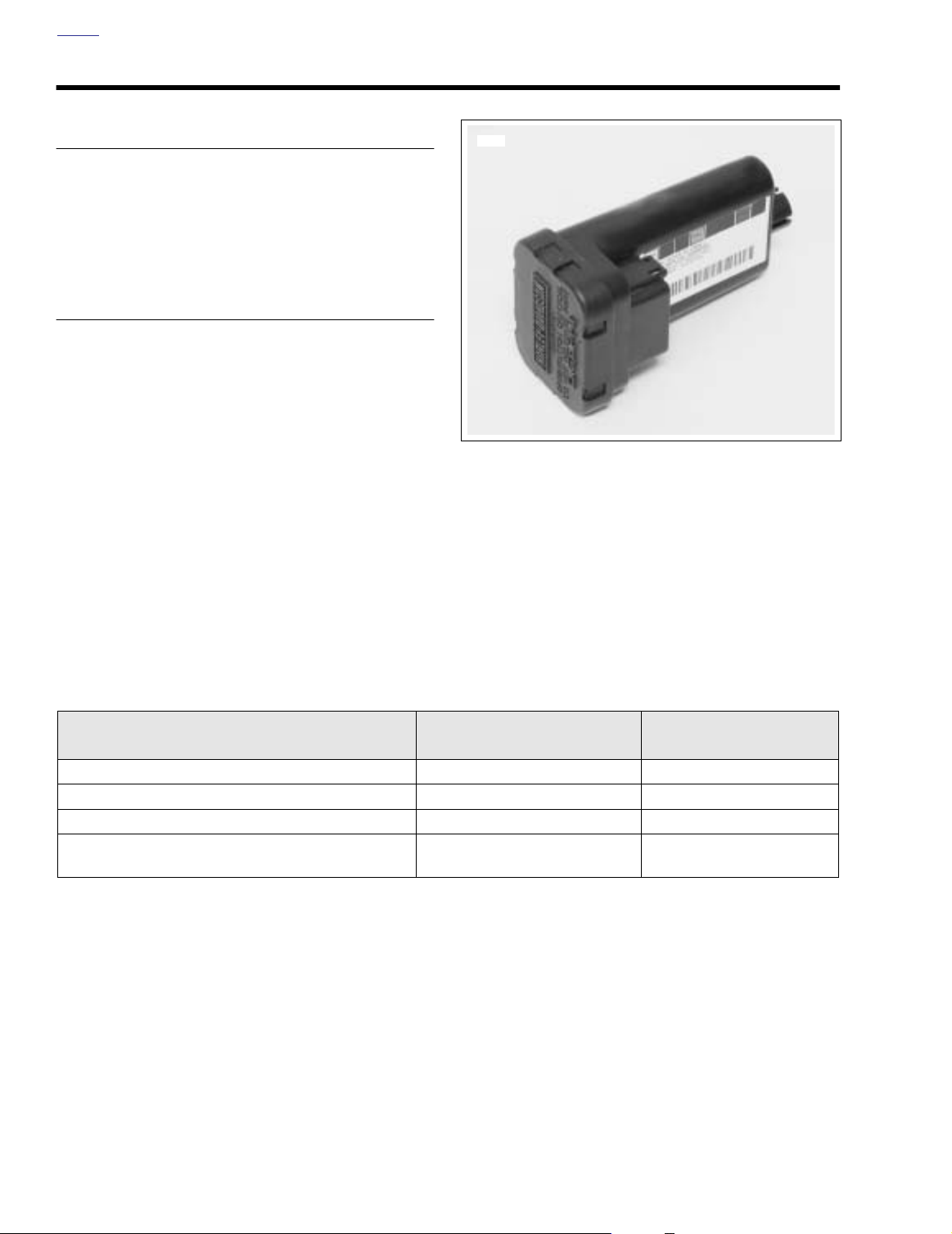
o0235xox
1
2
3
o0234xox
TSSM MAINTENANCE 3.25
GENERAL
The TSSM system uses batteries in the key fob and siren.
These are the only parts requiring periodic maintenance.
KEY FOB
Schedule
Replace the key fob battery every 2 years.
Battery Replacement
1. Open the key fob case.
a. Place a thin blade between the 2 halves of the case.
b. Slowly twist the blade.
2. See Figure 3-51. Replace battery.
a. Remove the original battery.
b. Install a new battery with the positive (+) side down.
Use a Panasonic
®
2032 or equivalent.
Figure 3-51. Open Key Fob Case
3. See Figure 3-52. Align case and circuit board as shown.
Snap case halves together.
4. While standing next to the motorcycle, press and hold
the key fob button for 10-15 seconds until the security
system responds with two turn signal flashes/siren
chirps.
Figure 3-52. Key Fob Assembly
2004 Touring: TSM & TSSM 3-83
Page 42

HOME
SIREN (IF INSTALLED)
Schedule
The siren’s internal 9 volt battery is rechargeable and does
not need to be replaced on a regular basis. Battery life under
normal conditions is approximately three to six years.
NOTE
The internal siren battery may not charge if the vehicle’s battery is less than 12.5 volts.
Battery Replacement
1. Disarm system and remove siren.
2. See Figure 3-53. Remove battery cover.
a. Place the siren module on a flat and sturdy table
with the potted section (area with epoxy covering circuit board) facing up and towards you.
b. Position a knife blade at a 45 degree angle to the
long side of the siren case. Insert the knife blade
between the siren case and battery cover at one of
the two accessible corners of the battery cover.
Keep the blade slightly higher towards the battery
cover as this helps keep the blade away from the
battery seal.
c. Slowly twist the blade towards the battery cover and
the cover will pop off.
7867
1
2
3
1. Cover
2. Battery
3. Siren Connector [142A]
Figure 3-53. Siren Battery Compartment
NOTE
For protection against corrosion, battery terminals and battery clip are covered with a special grease. Do not wipe away
this substance. Apply all available existing grease to terminals on new battery.
3. See Figure 3-53. Replace battery by removing old battery from polarized battery clip. Install a new 9 volt nickel
metal hydride battery.
NOTE
Only a nickel metal hydride nine-volt battery should be used
in the siren.
4. See Figure 3-53. Reinstall battery cover.
a. Carefully replace the rubber seal.
b. Align battery cover with case placing round corners
on cover away from connector [142A]. Snap cover
into place.
5. Install siren and check operation. If siren is working properly, it will respond with two chirps after receiving the arm
command.
3-84 2004 Touring: TSM & TSSM
 Loading...