

Page 1
H
f1368a8x
Set/Resume
Switch
0
30
50
40
110
120
60
70
80
90
100
0
20
30
70
80
40
50
60
10
MPH
H
A
R
L
E
Y
-
D
A
V
I
D
S
O
N
C
E
R
T
I
F
I
E
D
RPM
x100
H
A
R
L
E
Y
-
D
A
V
I
D
S
O
N
f2160x8x
Cruise Enabled/Engaged Lamp
Tachometer
OME
CRUISE CONTROL (FLHRC, FLTR, FLHTCU) 8.30
GENERAL
The Cruise Control system provides automatic vehicle speed
control. The electronics and stepper motor are contained in a
control module mounted under the left side cover. The stepper motor actuates the cruise control cable through a gear
train and ribbon reel.
SYSTEM OPERATION
To engage and disengage the cruise control system, proceed
as follows:
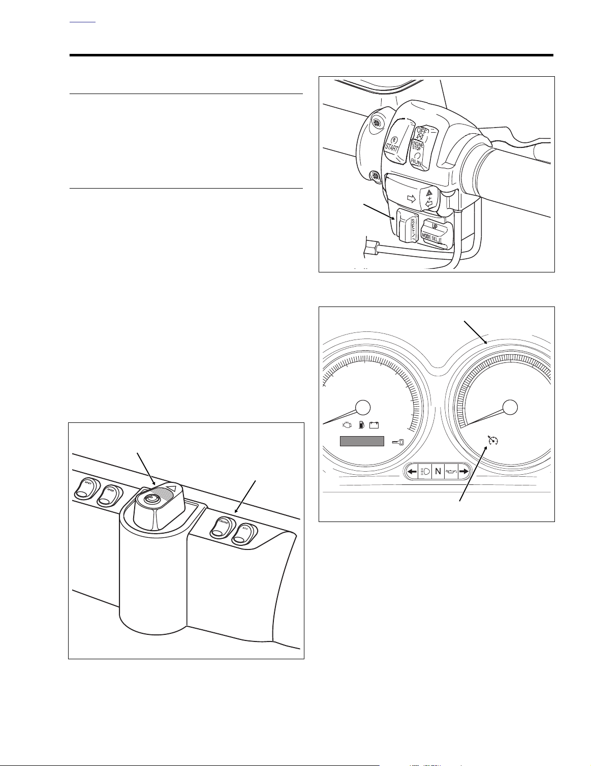
1. While riding in fourth or fifth gear, turn the Cruise ON/
OFF Switch to the ON position. See Figure 8-123. The
switch is located on the fairing cap of FLHTCU models,
the instrument nacelle of FLTR models, and the left handlebar lower switch housing on FLHRC models. The
Cruise Enabled/Engaged lamp in the tachometer face
(speedometer on FLHRC models) turns red to indicate
that the system is activated. See Figure 8-125. A red
lamp in the switch on both FLHTCU and FLTR models
also indicates this condition to the rider.
2. Power (12 vdc) is supplied to the cruise control module
through a 15 amp fuse located in the fuse block mounted
under the left side cover.
3. With the motorcycle traveling at the desired “cruise”
speed (30 mph/48 km/h to 85 mph/137 km/h), momentarily push the Cruise SET/RESUME switch to SET. See
Figure 8-124.
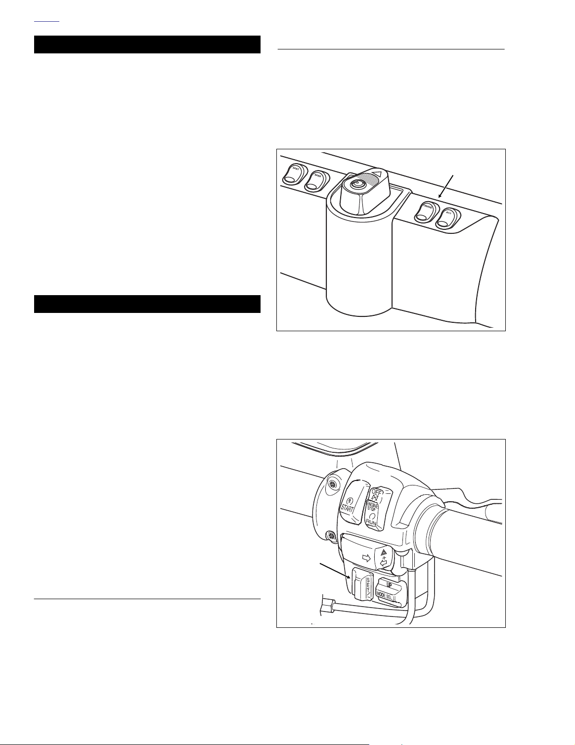
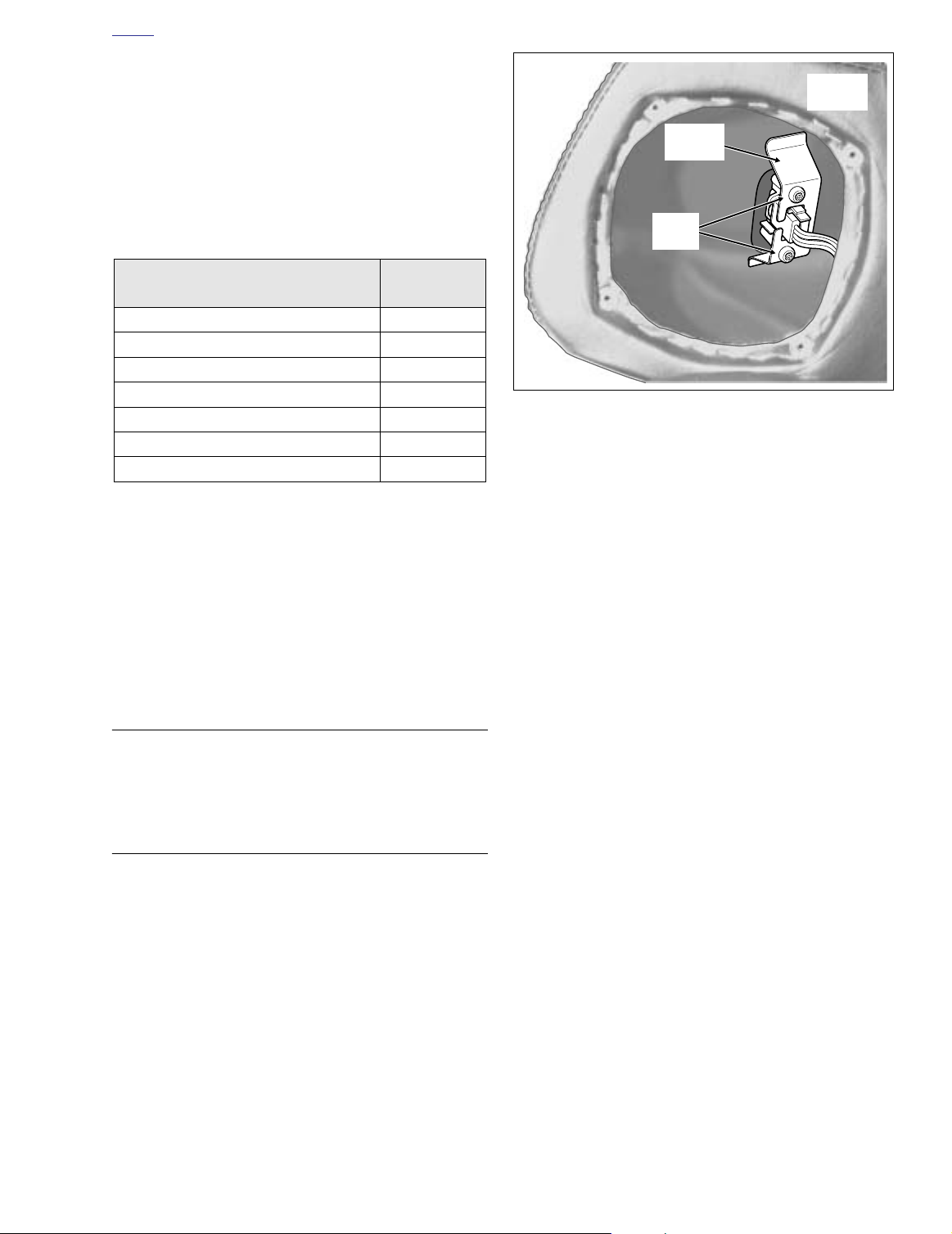
Figure 8-124. Right Handlebar Switch Assembly
(FLTR, FLHTCU)
Ignition/Light
Key Switch
Cruise ON/OFF
Switch
Figure 8-125. Instrument Panel (FLHTCU)
The cruise control module “reads” the vehicle speed
sensor (VSS) output to establish the desired vehicle
speed. The module then sends a signal to the stepper
motor which drives the ribbon reel to take up the slack in
the cruise cable. The Cruise Enabled/Engaged lamp in
the tachometer face (speedometer on FLHRC models)
turns from red to green to indicate that the cruising
speed is locked in. See Figure 8-125.
4. The cruise control module monitors both the engine
RPM and the VSS output speed signal. The module signals the stepper motor to open or close the throttle to
keep the speedometer output speed signal constant.
The engine RPM is monitored to detect engine
f2031x8x
Figure 8-123. Fairing Cap (FLHTCU)
2004 Touring: Electrical 8-99
Page 2
H
OME
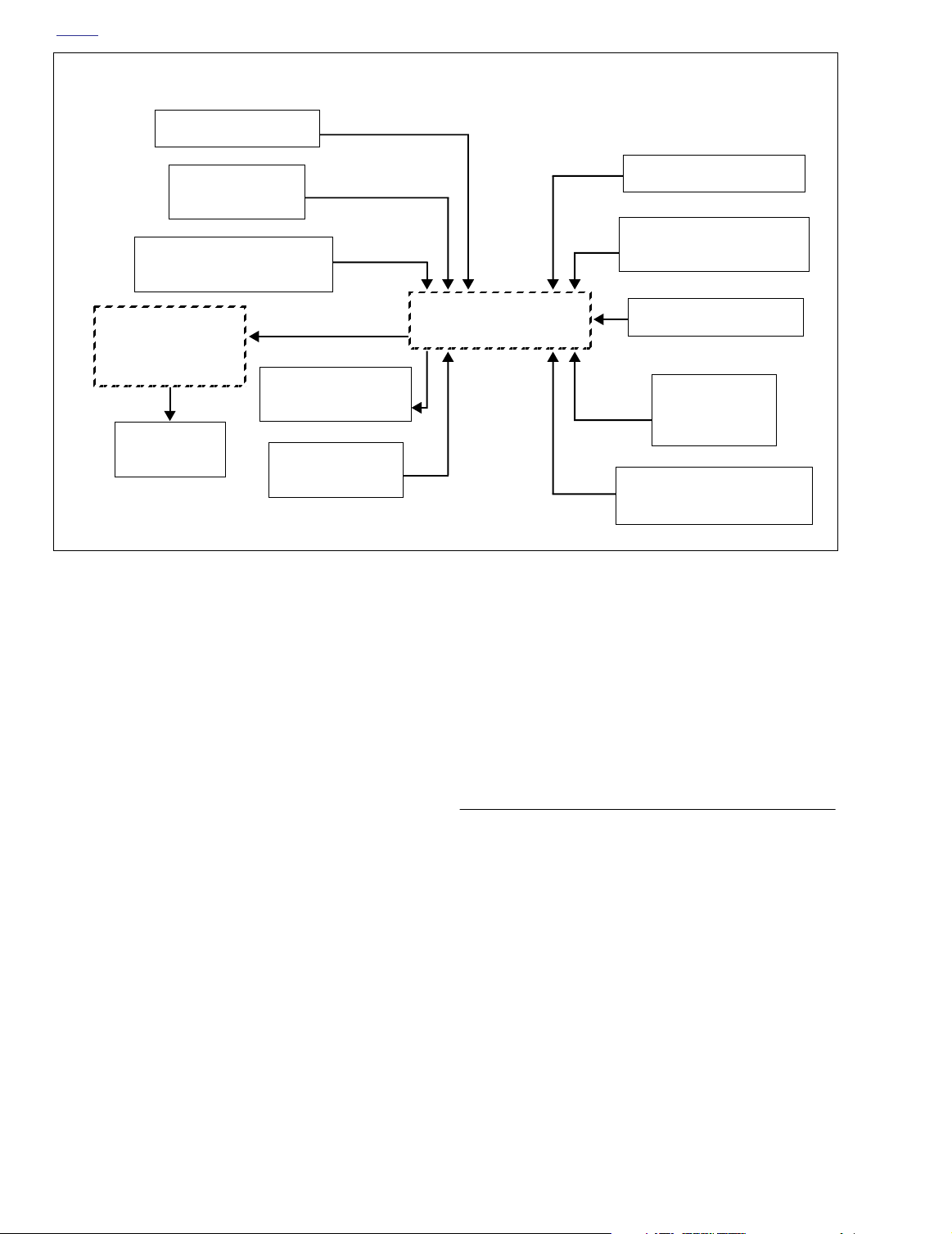
DISENGAGE SEQUENCEENGAGE SEQUENCE
CRUISE SWITCH ON
SET/RESUME
SWITCH TO SET
READS VSS
OUTPUT SPEED SIGNAL
STEPPER MOTOR
GEAR TRAIN
& RIBBON REEL
CRUISE ENGAGED
LAMP
THROTTLE
ACTUATION
*Tachometer receives signal from ignition coil on
carbureted models, and from ECM on EFI models.
overspeed, a condition which automatically causes
cruise disengagement.
5. The cruise control automatically disengages (stepper
motor drives cruise cable to the full-out position) whenever the cruise control module receives one of the following inputs:
a. Front or rear brake is applied.
b. Throttle is “rolled back” or closed, thereby actuating
idle cable roll-off (disengage) switch.
c. Motorcycle clutch is disengaged (module senses
too great an increase in RPM).
d. Cruise ON/OFF Switch placed in the OFF position.
The switch is located on the fairing cap of FLHTCU
models, the instrument nacelle of FLTR models, and
the left handlebar lower switch housing on FLHRC
models. The green Cruise Enabled/Engaged lamp
in the tachometer face (speedometer on FLHRC
models) is extinguished to indicate that the system
is deactivated. The red lamp in the fairing cap switch
of FLHTCU models and the instrument nacelle
switch of FLTR models is also extinguished.
e. Handlebar mounted Engine Stop Switch placed in
the OFF position. (This removes tachometer input
signal which results in module disengagement.)
ENGINE RPM
MONITORED*
Figure 8-126. Cruise System Diagram
FRONT/REAR BRAKE
IDLE CABLE ROLL-OFF
(DISENGAGE) SWITCH
CRUISE
MODULE
f. Handlebar mounted Cruise SET/RESUME switch is
pushed to SET and held in that position until vehicle
speed drops below 30 mph (48 km/h).
If the vehicle speed is above 30 mph (48 km/h) when the
Cruise SET/RESUME Switch is released, then the cruise
system automatically re-engages.
CRUISE SWITCH OFF
HANDLEBAR
ENGINE STOP
SWITCH OFF
CLUTCH DISENGAGE
(ENGINE RPM)
NOTE
CABLE ADJUSTMENT
NOTE
Always adjust the cables in the sequence presented below,
that is, throttle and then idle cable. The cruise cable only
requires adjustment if the cruise module or cruise cable are
removed or replaced, and then it must be adjusted last using
the CABLE LASH INITIALIZATION routine on the next page.
THROTTLE CABLE
1. With handlebar in straight ahead position, idle cable
adjusted to full slack and throttle control grip turned to
wide open throttle (WOT), adjust pull open cable to
obtain full throttle opening at carburetor/induction module.
8-100 2004 Touring: Electrical
Page 3

H
OME
2. Twist throttle grip to full closed position. Check that idle
stop-screw is touching idle stop with handlebar in
straight ahead position, and while turning handlebar
from “lock-to-lock”.
NOTE
If idle stop-screw is not touching idle stop, adjust (loosen)
pull-open cable just enough so that contact is made through
full lock-to-lock handlebar movement. Also check that cruise
cable has slack and is not opening throttle. Loosen cruise
cable if required.
3. Rotate throttle grip to WOT and release. Throttle must
return to idle position freely. If it does not, check for
incorrect cable routing, damaged cables or binding in the
throttle grip.
IDLE CABLE
1. Remove left side saddlebag. See Section 2.25 SAD-
DLEBAG, REMOVAL.
2. Gently pull side cover from frame downtubes (no tools
required).
3. Lift the locking latch and remove the cruise module connector [17]. With idle cable still adjusted to full slack position, connect ohmmeter to violet/yellow and orange/
violet leads on connector [17A].
4. Ohmmeter must indicate infinity (switch contacts open).
If ohmmeter indicates continuity, the roll-off switch may
be shorted and entire cable must be replaced.
5. With handlebar in straight ahead position, adjust idle
cable until approximately 0.06 inch (1.5 mm) of freeplay
exists at the outside diameter (OD) of the throttle grip.
6. With light force, rotate the throttle grip toward the closed
position. The ohmmeter must indicate continuity. If it
does not, decrease freeplay at throttle grip by adjusting
the idle cable to obtain continuity while maintaining
some freeplay at the throttle grip.
7. While holding the throttle grip (with light force) in the
closed position, turn handlebar from “lock-to-lock”. Ohmmeter must indicate continuity throughout handlebar
movement.
8. With handlebar in straight ahead position, rotate throttle
grip to WOT and release. Throttle must return to idle
position freely.
9. Repeat step 8 with handlebar at full left and right positions. If throttle does not return to idle position freely,
loosen idle cable slightly and repeat steps 6-9.
10. Install cruise module connector [17] and engage locking
latch.
11. Align barbed studs in side cover with grommets in frame
downtubes and push firmly into place (no tools
required).
12. Install left side saddlebag. See Section 2.25 SADDLE-
BAG, INSTALLATION.
CABLE LASH INITIALIZATION
With the elimination of the mechanical cruise cable adjuster,
the tolerance stack-ups are intended to result in a cable that
is too long. The extra cable length is then taken up upon execution of the Cable Lash Initialization routine. During the routine, the system calculates the number of “motor steps” the
cable is pulled before the throttle plates are moved (a maximum of 200 motor steps equivalent to 1.2 inches or 31 mm).
This information is then stored in permanent memory.
NOTE
Perform the initialization routine whenever the cruise module,
cruise cable or throttle body are removed or replaced. For
best results, be sure the engine is at normal operating temperature and throttle and idle cables are correctly adjusted
and operational.
To set the correct cable lash, proceed as follows:
a. Push the Cruise Switch on the right handlebar to
RESUME and hold
b. Tu rn the Cruise ON/OFF switch to ON.
c. Turn the Ignition/Light Key Switch to IGNITION.
d. Start the engine. The green Cruise Enabled/
Engaged lamp in the tachometer face (speedometer
on FLHRC models) will illuminate. Wait 3 seconds
for the lamp to go off.
e. Release the Cruise Switch from the RESUME posi-
tion.
f. Push the Cruise Switch to RESUME and hold
Cruise will pull in cable until change in RPM is
detected. The number of motor steps required to rev
the engine is stored in memory.
g. After engine revs and Cruise Enabled/Engaged
lamp is extinguished, release the Cruise Switch
from the RESUME position.
h. Turn the Ignition/Light Key Switch to OFF.
.
THROTTLE/IDLE CABLES
NOTE
While the same throttle cable is used on all Touring models,
the idle cable of “cruise” models is provided with a cruise rolloff (disengage) switch.
REMOVAL
1. See Section 2.21 THROTTLE CABLES (NON-CRUISE),
REMOVAL, THROTTLE SIDE.
2. Remove the air cleaner and backplate. See Section 4.5
AIR CLEANER, REMOVAL.
3. Raise fuel tank to access cables in area of frame back-
bone. For carbureted models, see Section 4.7 FUEL
TANK (CARBURETED), PA RTIAL REMOVAL, FLHT/C,
or FLHR/S. For fuel injected models, see Section 9.4
FUEL TANK (FUEL INJECTED), PARTIAL REMOVAL,
FLHT/C/U/I, FLTRI, or FLHR/C/S/I.
.
2004 Touring: Electrical 8-101
Page 4
H
OME
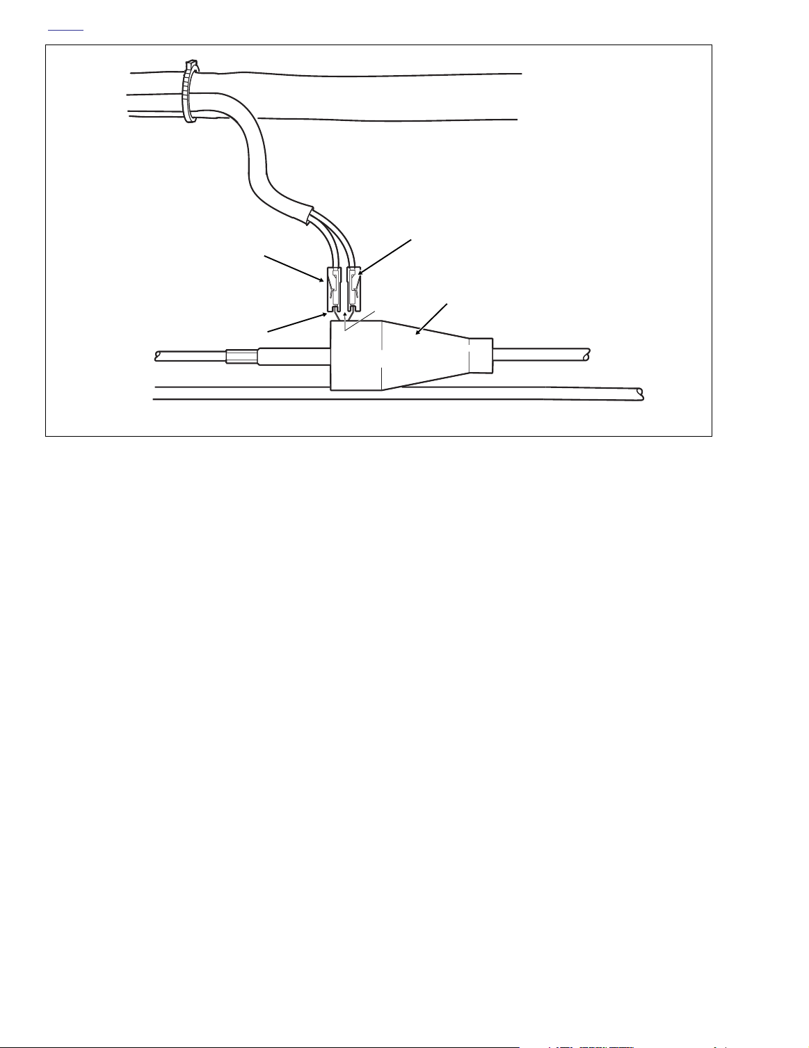
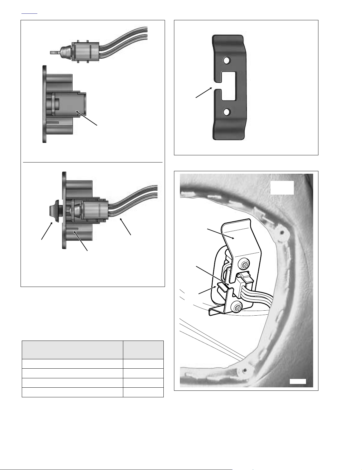
Insulator
Switch Spade
Contact
Female Spade
External
Step
Main
Harness
Terminal
Cruise Control
Roll-Off Switch
(Under Boot)
Idle Cable
f2037x8x
Figure 8-127. Throttle/Idle Cable Configuration (Right Side View)
4. Locate the cruise control roll-off switch plumbed into the
idle cable on the right side of the vehicle. See Figure 8-
127. Push rubber boot on switch forward to access
spade type wire terminals.
5. Remove both female spade type terminals from spade
contacts on cruise control roll-off switch.
6.
Carbureted:
Using a needle nose pliers, carefully pull
idle cable barrel from upper inboard hole in throttle
wheel. Pull throttle cable barrel from remaining hole.
Release idle and throttle cables from guides in throttle
cable bracket.
Induction Module:
Using a needle nose pliers, carefully
pull idle cable barrel from upper hole in throttle wheel.
Pull throttle cable barrel from lower hole. Using slots,
release idle and throttle cables from guides in throttle
cable bracket.
7. Free cables from J-clamp riveted to right side of frame
backbone.
8. If present, remove screw (with flat washer) to release Jclamp from wellnut in right side of steering head.
Remove J-clamp from cables.
INSTALLATION
1. See Section 2.21 THROTTLE CABLES (NON-CRUISE),
INSTALLATION, THROTTLE SIDE.
Throttle Cable
2. Route the throttle and idle cables as follows:
FLHTCU:
Route the cables downward following the
brake line to the inner fairing. Pass the cables through
the inner fairing grommet and then loop them toward the
rear along the right side of the steering head.
FLHRC:
Route the cables downward following the right
handlebar to the handlebar clamp shroud. Pass the
cables through the opening in the shroud and then loop
them toward the rear along the right side of the steering
head. Capture cables in J-clamp and then start screw
(with flat washer) to fasten J-clamp to wellnut in right
side of steering head. Tighten screw to 9-18
in-lbs
(1.0-
2.0 Nm).
3. Route the throttle and idle cables rearward along the
right side of the frame backbone. After passing through
J-clamp riveted to frame backbone, route cables downward to carburetor/induction module.
4. Use a pliers to straighten spade contacts of cruise rolloff switch if bowed or bent back. The contacts must be
parallel and line up perpendicular to the idle cable.
5. Separate the cruise roll-off switch wires up to the point
where they enter the wire harness conduit. Now route
the leads straight down.
6. Orient the idle cable so that the spade contacts are at
the top.
8-102 2004 Touring: Electrical
Page 5
H
OME
7. Slide the insulators onto the switch spade contacts
(polarity is not a factor). For maximum insertion, be sure
that the external step on the insulators face each other.
See Figure 8-127.
8. Fit the rubber boot over the cruise control roll-off switch.
An oval cut in the boot accommodates the switch spade
terminal connections.
9. Position the throttle cable below the idle cable.
10.
Carbureted:
shorter cable guide in throttle cable bracket. Drawing
throttle cable downward, fit barrel end into lower outboard hole in throttle wheel. Install sleeve and spring on
idle cable housing into longer cable guide inserting barrel end into upper inboard hole in throttle wheel.
Induction Module:
ing into shorter cable guide at top of throttle cable
bracket. Drawing throttle cable downward, fit barrel end
into lower hole in throttle wheel. Install sleeve and spring
on idle cable housing into longer cable guide at bottom
of throttle cable bracket inserting barrel end into upper
hole in throttle wheel.
11. Verify that cables are fully seated in channel of throttle
wheel, and using cable adjusters at handlebar, tighten
Install sleeve on throttle cable housing into
Install sleeve on throttle cable hous-
cables as necessary to keep barrel ends from dislodging. Verify operation by turning throttle grip and observing cable action.
12. Install fuel tank. For carbureted models, see Section 4.7
FUEL TANK (CARBURETED), INSTALLATION (AFTER
PA RTIAL REMOVAL), FLHT/C, or FLHR/S. For fuel
injected models, see Section 9.4 FUEL TANK (FUEL
INJECTED), INSTALLATION (AFTER PARTIAL
REMOVAL), FLHT/C/U/I, FLTRI, or FLHR/C/S/I.
13. Install backplate and air cleaner assembly. See Section
4.5 AIR CLEANER, INSTALLATION.
14. Adjust the throttle and idle cables. Be sure to use the
cable adjustment procedure for Ultra models. See
CABLE ADJUSTMENT, in this section.
CRUISE CABLE
REMOVAL
1. Remove the air cleaner and backplate. See Section 4.5
AIR CLEANER, REMOVAL.
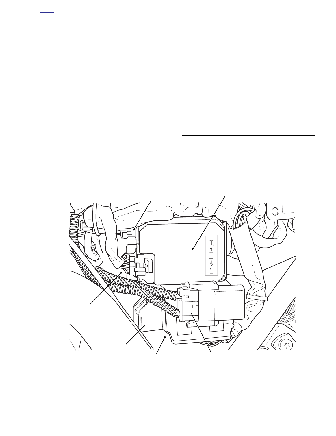
f2206x8x
Cruise Module
Connector [17]
Spare Fuse
Holder
Cruise Cable
Connector
Fuse Block
Cruise Module
Maxi-Fuse
Holder
Figure 8-128. Cruise Control Module (Under Left Side Cover)
2004 Touring: Electrical 8-103
Page 6
H
OME
f1965x8x
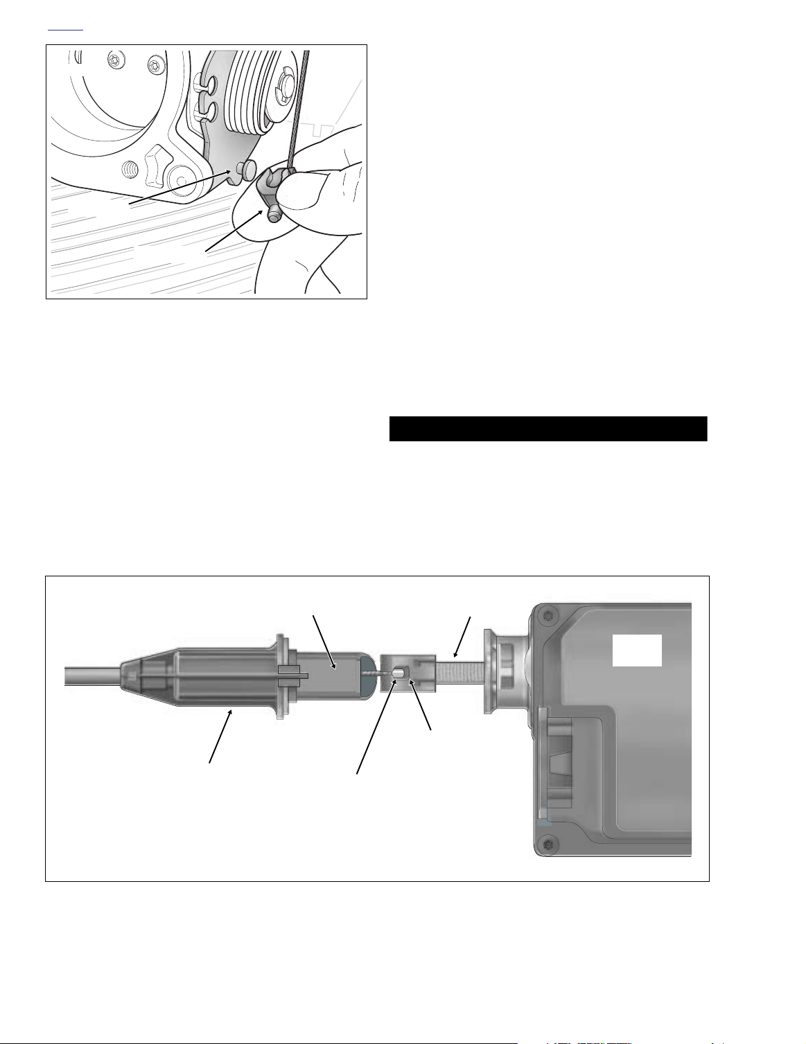
7. Pull the cable out of the connector and remove the cable
end bead from the ribbon end eyelet. See Figure 8-130.
8. Pull anchored cable clip from hole in frame crossmember. See Figure 8-131.
9. Carefully pull cruise cable from beneath fuel tank drawing it out through hole in frame crossmember.
INSTALLATION
Wheel Pin
End Fitting
Figure 8-129. Remove End Fitting From Wheel Pin
2. Remove E-clip from sleeve at end of cruise cable housing. Discard E-clip. Using slot, remove cruise cable
housing from cable guide in throttle cable bracket.
3. Push the plastic end fitting on the cruise cable to the outboard side to release from wheel pin. See Figure 8-129.
4. Remove left side saddlebag. See Section 2.25 SAD-
DLEBAG, REMOVAL.
5. Gently pull side cover from frame downtubes (no tools
required).
6. Rotate cruise cable connector in a counterclockwise
direction to detach from cruise module. See Figure 8-
128.
Flat
1. Draw the cruise cable forward along the left side of the
frame backbone, and then route the cable toward the
right side of the vehicle in front of the top engine stabilizer bracket.
2. Slide groove in cruise cable end fitting over cap of wheel
pin. Push on end fitting until it snaps in place. See Figure
8-129.
3. Using slot, slip cruise cable housing into cable guide in
throttle cable bracket. At bottom of bracket, install
new
E-clip on sleeve at end of cruise cable housing.
4. Feed cruise cable and connector through hole in frame
crossmember. See Figure 8-131.
CAUTION
Be sure that the ribbon is not twisted. A twisted ribbon
may adversely affect performance or even prevent cruise
operation.
5. With the hole in the ribbon end eyelet and the flat on the
cable connector housing facing outboard, fit cable end
bead into ribbon end eyelet. See Figure 8-130.
Ribbon
Cruise Cable
Connector
f1549x8x
Figure 8-130. Remove Cable End Bead From Ribbon End Eyelet
8-104 2004 Touring: Electrical
Cruise
Module
Ribbon End
Eyelet
Cable End
Bead
Page 7

H
1WARNING1WARNING
f2004x8x
Mounting
Holes
OME
f1548x8x
Cruise
Cable
Cable Clip
Hole
Figure 8-131. Cruise Cable Routing (Left Side)
6. Verify that bead, eyelet and ribbon are lined up correctly.
If necessary, remove plastic end fitting from wheel pin
and gently pull on end fitting to remove cable slack.
Reinstall end fitting, if removed.
7. Insert cruise cable connector into cruise module and
rotate in a clockwise direction until tabs on connector
fully engage grooves or detentes in cruise module housing.
8. Capture cruise cable in cable clip and anchor in hole of
frame crossmember. See Figure 8-131.
9. Adjust the throttle and idle cables. See CABLE ADJUST-
MENT, in this section.
10. Install backplate and air cleaner assembly. See Section
4.5 AIR CLEANER, INSTALLATION.
11. Align barbed studs in side cover with grommets in frame
downtubes and push firmly into place (no tools
required).
12. Install left side saddlebag. See Section 2.25 SADDLE-
BAG, INSTALLATION.
13. Perform the CABLE LASH INITIALIZATION routine des-
cribed in this section.
Always disconnect the negative battery cable first. If the
positive cable should contact ground with the negative
cable installed, the resulting sparks may cause a battery
explosion which could result in death or serious injury.
4. Unthread bolt and remove battery negative cable (black)
from battery negative (-) terminal.
5. Unthread bolt and remove battery positive cable (red)
from battery positive (+) terminal.
6. Using a T40 TORX drive head, loosen bolt to move lip of
hold-down clamp off edge of battery. Remove battery
from battery box.
7. Lift the locking latch and remove the cruise module connector [17]. See Figure 8-128.
8. Rotate cruise cable connector in a counterclockwise
direction to detach from cruise module.
9. From inside battery box, remove three flange bolts.
Carefully pull cruise module away from side of battery
box exercising caution to avoid losing grommets.
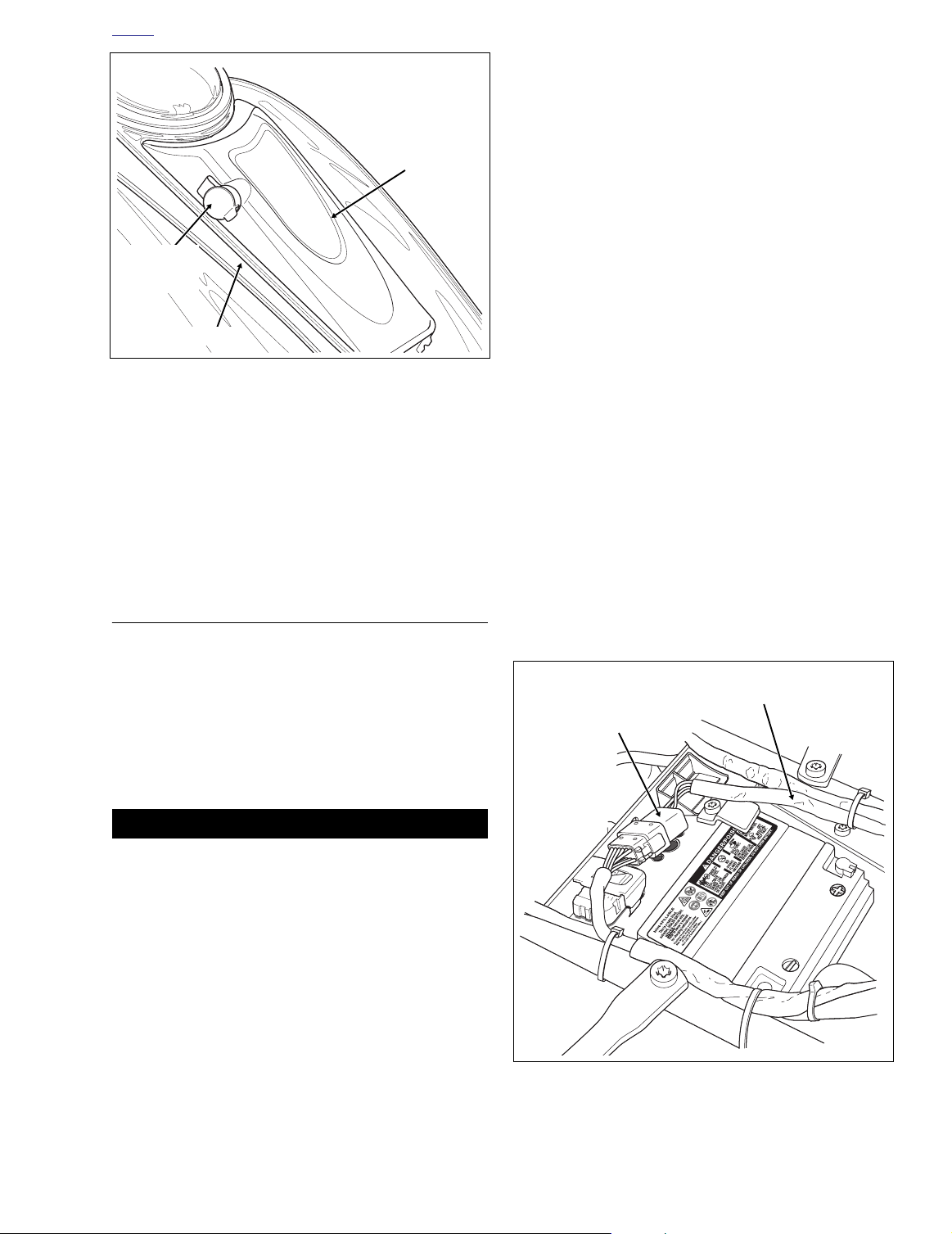
INSTALLATION
1. Install grommets into holes on left side of battery box
with the larger OD on the outboard side. See Figure 8-
132.
2. Align threaded holes on inboard side of cruise module
with holes in grommets and install flange bolts from
inside battery box.
3. Alternately tighten flange bolts to 60-96
Nm). Install cruise module connector [17] and engage
locking latch.
in-lbs
(6.8-10.9
CRUISE CONTROL MODULE
REMOVAL
1. Remove the air cleaner and backplate. See Section 4.5
AIR CLEANER, REMOVAL.
2. Push the plastic end fitting on the cruise cable to the outboard side to release from wheel pin. See Figure 8-129.
3. Remove seat. See Section 2.24 SEAT, REMOVAL.
Figure 8-132. Battery Box (Right Side View)
2004 Touring: Electrical 8-105
Page 8
H
OME
CAUTION
Be sure that the ribbon is not twisted. A twisted ribbon
may adversely affect performance or even prevent cruise
operation.
4. With the hole in the ribbon end eyelet and the flat on the
cable connector housing facing outboard, fit cable end
bead into ribbon end eyelet. See Figure 8-130.
5. Verify that bead, eyelet and ribbon are lined up correctly.
If necessary, remove plastic end fitting from wheel pin
and gently pull on end fitting to remove cable slack.
6. Insert cruise cable connector into cruise module and
rotate in a clockwise direction until tabs on connector
fully engage grooves or detentes in cruise module housing.
7. Install the cruise module connector [17] until locking
latch engages. See Figure 8-128.
8. Place battery in battery box, terminal side forward.
Rotate hold-down clamp so that lip (with rubber pad)
rests on edge of battery and tighten clamp bolt.
1WARNING1WARNING
Always connect the positive battery cable first. If the
positive cable should contact ground with the negative
cable installed, the resulting sparks may cause a battery
explosion which could result in death or serious injury.
CRUISE CONTROL SWITCHES
FAIRING CAP
See Figure 8-133. For instructions on replacement of the
CRUISE ON/OFF SWITCH, see Section 8.19 FAIRING
CAP SWITCHES (FLHTC/U), Section 8.20 INSTRUMENT NACELLE SWITCHES (FLTR), or Section 8.21
HANDLEBAR SWITCHES (FLHRC).
Cruise ON/OFF
Switch
f2031x8x
Figure 8-133. Fairing Cap (FLHTCU)
9. Insert bolt through battery positive cable (red) into
threaded hole of battery positive (+) terminal. Tighten
bolt to 60-96
10. Insert bolt through battery negative cable (black) into
threaded hole of battery negative (-) terminal. Tighten
bolt to 60-96
11. Install seat. See Section 2.24 SEAT, INSTALLATION.
12. Slide groove in cruise cable end fitting over cap of wheel
pin. Push on end fitting until it snaps in place. See Figure
8-129.
13. Install backplate and air cleaner assembly. See Section
4.5 AIR CLEANER, INSTALLATION.
14. Perform the CABLE LASH INITIALIZATION routine des-
cribed in this section.
in-lbs
in-lbs
(6.8-10.9 Nm).
(6.8-10.9 Nm).
AUDIO HARNESS
For instructions on replacement of the audio harness,
see Section 8.32 WIRING HARNESSES AND CABLES,
AUDIO HARNESS (FLHTCU).
HANDLEBAR
See Figure 8-134. For instructions on replacement of the
handlebar mounted CRUISE SET/RESUME switch, see
Section 8.21 HANDLEBAR SWITCHES, SWITCH
REPAIR/REPLACEMENT.
f1368a8x
Set/Resume
Switch
Figure 8-134. Right Handlebar Switch Assembly
(FLTR, FLHTCU)
8-106 2004 Touring: Electrical
Page 9
H
f2238x8x
Radio Antenna
Cable [51]
Radio [27]
Black
CB Antenna
Cable [50]
Ultra Only
Radio [28]
Gray
Ultra Only
1. Main to Interconnect [1]
2. Main to Interconnect [15]
3. Ignition/Light Key Switch [33]
1 2 3
f1559x8x
OME
PREMIUM SOUND SYSTEM (FLHTC/U, FLTR) 8.31
RADIO (FLHTC/U)
REMOVAL
1. Remove seat. See Section 2.24 SEAT, REMOVAL.
1WARNING1WARNING
To protect against shock and accidental start-up of vehicle, disconnect the negative battery cable before proceeding. Inadequate safety precautions could result in
death or serious injury.
CAUTION
To prevent possible damage to the sound system,
always verify that the Ignition/Light Key Switch is in the
OFF position before disconnecting the battery negative
cable from the battery terminal.
2. Verify that the Ignition/Light Key Switch is in the OFF
position. Unthread bolt and remove battery negative
cable (black) from battery negative (-) terminal.
3. Remove the outer fairing. See Section 2.29 UPPER
FAIRING/WINDSHIELD (FLHT/C/U), OUTER FAIRING/
WINDSHIELD, REMOVAL.
NOTE
To separate pin and socket halves of Radio connectors [27]
and [28], use thumbnail to pull down external latch before
pulling socket from pin side. See Figure 8-135.
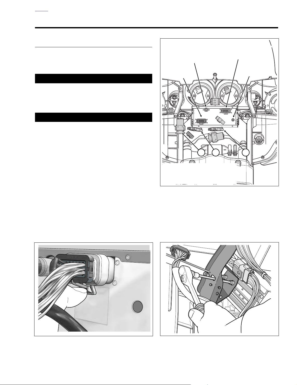
4. See Figure 8-136. Separate pin and socket halves of the
following connectors:
a. Radio connector [27], 23-place Amp (black).
f1555x8x
Figure 8-136. Radio Connections - FLHTCU
b. Radio antenna cable connector [51].
c. Radio connector [28], 23-place Amp (gray).
models only.
d. CB antenna cable connector [50]. Rotate knurled
nut counterclockwise until free.
Ultra models only.
Ultra
Figure 8-135. Pull Down Latch to Free Radio Connector
Figure 8-137. Release Carrier from Fairing Brackets
2004 Touring: Electrical 8-107
Page 10

H
OME
5. Move the following connectors from their fixed locations:
a. Main to interconnect harness connector [1], 12-
place Deutsch (black); T-stud at front of right fairing
bracket.
b. Main to interconnect harness connector [15], 4-
place Packard (black); anchor in hole at bottom of
radio (right side).
c. Ignition/light key switch connector [33], 4-place
Packard; anchor in hole at bottom of radio (center).
6. Using a long shank ball end socket (Snap-on® FABL6E),
remove four screws to release radio from left and right
radio support brackets. Use oblong holes in fairing
brackets to access screws. See Figure 8-137.
7. Pull radio forward to remove. If radio nose seal gets
caught on radio support brackets, rock up and down until
free.
INSTALLATION
1. Position radio between radio support brackets and push
into approximate position. If radio nose seal gets caught
on radio support brackets, rock up and down while pushing. If necessary, spray nose seal with contact cleaner
and repeat step.
2. Before pushing radio into cut of inner fairing, verify that
nose seal is not distorted, compressed or pinched.
3. Align threaded inserts in radio sides with oblong holes in
left and right radio support brackets. Starting with the
rear screws, install four socket screws to fasten radio to
brackets. Tighten screws to 35-45
4. See Figure 8-136. Mate pin and socket halves of the following connectors:
a. Radio connector [27], 23-place Amp (black).
b. Radio antenna cable connector [51].
c. Radio connector [28], 23-place Amp (gray).
models only.
d. CB antenna cable connector [50]. Insert pin and
rotate knurled nut clockwise until tight.
only.
5. Return the following connectors to their fixed locations:
a. Main to interconnect harness connector [1], 12-
place Deutsch (black); T-stud at front of right fairing
bracket.
b. Main to interconnect harness connector [15], 4-
place Packard (black); anchor in hole at bottom of
radio (right side).
c. Ignition/light key switch connector [33], 4-place
Packard; anchor in hole at bottom of radio (center).
in-lbs
(4.0-5.1 Nm).
Ultra
Ultra models
6. Install outer fairing. See Section 2.29 UPPER FAIRING/
WINDSHIELD (FLHT/C/U), OUTER FAIRING/WINDSHIELD, INSTALLATION.
CAUTION
To prevent possible damage to the sound system,
always verify that the Ignition/Light Key Switch is in the
OFF position before connecting the battery negative
cable to the battery terminal.
7. Verify that the Ignition/Light Key Switch is in the OFF
position. Insert bolt through battery negative cable
(black) into threaded hole of battery negative (-) terminal. Tighten bolt to 60-96
8. Install seat. See Section 2.24 SEAT, INSTALLATION.
in-lbs
(6.8-10.9 Nm).
FRONT FAIRING SPEAKERS
REMOVAL
1. Remove the outer fairing. See Section 2.29 UPPER
FAIRING/WINDSHIELD (FLHT/C/U), OUTER FAIRING/
WINDSHIELD, REMOVAL.
2. Carefully pull the socket terminals from the speaker
spade contacts.
3. Using a T25 TORX drive head, remove three screws to
release the speaker adapter assembly from the inner
fairing.
4. Carefully pull speaker from adapter.
INSTALLATION
1. With the speaker spade contacts at the top of the
adapter, the top being the side with the widest edge,
snap speaker into adapter using finger pressure.
2. If speaker grille is loose, apply 3M-847 adhesive (HD
Part No. 99618-60) to outer edge of adapter ring. Install
grille on adhesive.
3. With the widest edge of adapter at the top, align holes in
speaker adapter assembly with those in inner fairing.
4. Install two long screws to secure top of speaker adapter
assembly to inner fairing. Capturing fairing support
brace, install short screw in lower outboard hole (positioning flat washer between adapter and support brace).
The screw hole on the lower inboard side is not used.
5. Using a T25 TORX drive head, tighten the lower speaker
screw to 22-28
upper speaker screws to 35-50
in-lbs
(2.5-3.2 Nm). Tighten the two
in-lbs
(4.0-5.7 Nm).
8-108 2004 Touring: Electrical
Page 11
H
f2192x8x
Console Pod
Cable Conduit
Console Pod
Connector [53]
12-Place Mini-Deutsch
OME
Fuel
Door
Headset
Receptacle
Cap
Console
Figure 8-138. Console Pod Assembly
6. Install the socket terminals onto the speaker spade contacts. Different size spade contacts prevent improper
assembly.
7. Install the outer fairing. See Section 2.29 UPPER FAIR-
ING/WINDSHIELD (FLHT/C/U), OUTER FAIRING/
WINDSHIELD, INSTALLATION.
f2019x8x
Pod
CONSOLE POD ASSEMBLY
5. Carefully cut anchored cable strap securing main harness, audio harness, console pod conduit, fuel level
sender/fuel pump conduit, and fuel vapor vent tube to
left side of frame backbone. Cut cable strap securing
console pod conduit and audio harness to left frame
tube at front of saddlebag rail.
6. Open fuel door on console. Remove two Allen head
screws inboard of rubber bumpers. These screws secure
console to clip nuts on the canopy bracket.
7. Remove Allen head screw to detach flange at rear of
console from clip nut on fuel tank weldment.
8. Lay a clean shop towel on forward part of the rear
fender. Remove filler cap from neck of fuel tank. Remove
console and lay upside down on shop towel. Reinstall
filler cap.
9. Bend back flexible clamp to release pod cable conduit
from bottom of console.
10. Release Console Pod Connector [53], 12-place MiniDeutsch, from attachment clip anchored in hole of frame
crossmember (at rear of battery box). See Figure 8-139.
Depress external latches and use a rocking motion to
separate pin and socket halves.
11. Remove three Phillips screws to release pod from console.
INSTALLATION
1. Feed pin housing and conduit through top of console
seating pod in recess. Install three Phillips screws
screws to secure pod to console. Alternately tighten
screws to 6-11
flexible clamp at bottom of console.
in-lbs
(0.7-1.2 Nm). Capture conduit in
The following instructions may also be used for replacement
of the chrome fuel tank console on which the pod is mounted.
REMOVAL
1. Remove seat. See Section 2.24 SEAT, REMOVAL.
To protect against shock and accidental start-up of vehicle, disconnect the negative battery cable before proceeding. Inadequate safety precautions could result in
death or serious injury.
2. Unthread bolt and remove battery negative cable (black)
3. Remove left side saddlebag. See Section 2.25 SAD-
4. Gently pull side cover from frame downtubes (no tools
NOTE
1WARNING1WARNING
from battery negative (-) terminal.
DLEBAG, REMOVAL.
required).
Figure 8-139. Disconnect Console Pod Connector
2004 Touring: Electrical 8-109
Page 12

H
OME
Fuel
Tank
Fuel Pump,
Fuel Level
Sender Conduit
Console
Pod
f2007x9x
6. Mate pin and socket halves of Console Pod Connector
[53], 12-place Mini-Deutsch. Install connector onto
attachment clip anchored in hole of frame crossmember
(at rear of battery box).
7. Insert bolt through battery negative cable (black) into
threaded hole of battery negative (-) terminal. Tighten
bolt to 60-96
8. Install seat. See Section 2.24 SEAT, INSTALLATION.
9. Align barbed studs in side cover with grommets in frame
downtubes and push firmly into place (no tools
required).
10. Install left side saddlebag. See Section 2.25 SADDLE-
BAG, INSTALLATION.
in-lbs
(6.8-10.9 Nm).
Main
Harness
Bundle
Console
Pod Conduit
Figure 8-140. Console Pod Cable/Hose Routing
Fuel Vapor
Vent Tube
(To Vapor Valve)
Anchored
Cable Strap
(Top View)
Fuel
Overflow
Hose
Main
Harness
Bundle
1WARNING1WARNING
Exercise caution to avoid pinching or kinking the fuel
overflow hose when console is installed. A blocked hose
can cause excess gasoline to remain above the filler
neck insert, while fuel expansion can cause an overfilled
tank to overflow through the filler cap vent. Gasoline is
extremely flammable and highly explosive. Inadequate
safety precautions could result in death or serious
injury.
2. Remove filler cap. Place console over filler neck onto
canopy. Route cables from beneath console as shown in
Figure 8-140. Be sure that hoses and wires are not
pinched by the console during installation. Reinstall filler
cap.
3. Install Allen head screw to fasten rear flange of console
to clip nut on fuel tank weldment. Tighten screw to 25-30
in-lbs
(2.8-3.4 Nm).
4. Open fuel door on console. Install two Allen head screws
to secure front of console to clip nuts on canopy bracket.
Alternately tighten screws to 25-30
5. Snap anchor of
frame backbone. Tighten cable strap capturing main harness, audio harness, console pod conduit, fuel level
sender/fuel pump conduit, and fuel vapor vent tube. See
Figure 8-140. Install
pod conduit and audio harness to left frame tube at front
of saddlebag rail. Cut any excess cable strap material.
new
cable strap into hole on left side of
new
cable strap to secure console
in-lbs
(2.8-3.4 Nm).
FRONT HEADSET RECEPTACLE
REMOVAL
1. Remove console pod. See CONSOLE POD ASSEM-
BLY, REMOVAL, in this section.
2. Remove terminals 6 through 12 from pin housing of 12place Mini-Deutsch connector.
NOTE
For instructions on properly removing wire terminals, see
APPENDIX B.1 DEUTSCH ELECTRICAL CONNECTORS,
REMOVING/INSTALLING PINS.
3. Raise headset receptacle cap. Place pin punch in either
notch of lock ring and rotate in a counterclockwise direction until loose. See Figure 8-141.
4. Remove lock ring and cap from headset receptacle.
5. Remove headset receptacle from pod.
INSTALLATION
1. From inside pod, insert threaded end of headset recep-
tacle through side hole.
Lock Ring
f2020x8x
Figure 8-141. Remove Lock Ring from Receptacle
Using Pin Punch
8-110 2004 Touring: Electrical
Page 13
H
f1492b8x
Speaker
Box
Switch
Bracket
TORX
Screw
OME
2. Place receptacle cap over end of headset receptacle so
that it seats in recess of pod.
3. Open cap, and with the notches on the outboard side,
thread lock ring onto headset receptacle.
4. Place pin punch in either notch of lock ring and rotate in
a clockwise direction until tight.
5. Install terminals 6 through 12 into pin housing of 12place Mini-Deutsch connector.
Table 8-16. Front Headset Receptacle
Wire Color
Blue/Yellow 6
Ye llow/Black 7
Yellow/White 8
Yellow/Red 9
Black 10
Red 11
Black (Thick Insulation) 12
NOTE
For instructions on properly installing wire terminals, see
APPENDIX B.1 DEUTSCH ELECTRICAL CONNECTORS,
REMOVING/INSTALLING PINS.
6. Install console pod. See CONSOLE POD ASSEMBLY,
INSTALLATION, in this section.
7. Test operation of headset receptacle.
Chamber
Number
REAR HEADSET RECEPTACLE
See Section 8.32 WIRING HARNESSES AND CABLES,
AUDIO HARNESS (FLHTCU).
REAR PASSENGER SWITCHES
REMOVAL
NOTE
Right and left side replacement passenger switch assemblies are interchangeable.
1. Remove maxi-fuse. See Section 8.3 SYSTEM FUSES,
MAXI-FUSE, REMOVAL.
2. Open Tour-Pak.
3. Using a T10 TORX drive head, remove four screws and
pull speaker grille from speaker box.
Figure 8-142. Remove Passenger Switch Assembly
(Right Side Speaker Box Shown)
4. Remove speaker from speaker box and carefully pull
socket terminals from speaker spade contacts.
5. Remove trim ring and gently pull on wire harness to
draw 6-place Mini-Deutsch connector out of speaker
box.
6. Depress external latch on socket housing side and use a
rocking motion to separate pin and socket halves of
Mini-Deutsch connector.
7. Draw socket half of Mini-Deutsch connector back into
speaker box and pull out through speaker hole.
8. Using a T25 TORX drive head, remove two screws to
release switch bracket from inside of speaker box.
Remove bracket using slot to free switch wires. See Fig-
ure 8-142.
9. Pull switch housing assembly, wire harness conduit,
speaker terminals and Mini-Deutsch socket from
speaker box using switch housing hole on outboard side.
10. Carefully pull keycap from switch shaft. Remove switch
from switch housing.
11. Remove terminals 1 through 4 from socket housing.
NOTE
For instructions on properly removing wire terminals, see
APPENDIX B.1 DEUTSCH ELECTRICAL CONNECTORS,
REMOVING/INSTALLING SOCKETS.
12. Pulling one wire at a time, remove four wires from conduit.
INSTALLATION
1. Pushing one wire at a time, feed four wires of
through conduit.
new
switch
2004 Touring: Electrical 8-111
Page 14
H
OME
f1494b8x
Passenger
Cavity
Switch
Slot
Slot faces toward the front
on right side switch assembly,
toward the rear on left side.
Switch
Housing
Keycap
DISASSEMBLED
Pink/White
Wire
Rib
f1495x8x
ASSEMBLED
Figure 8-143. Install Switch in Housing
2. Install terminals 1 through 4 into socket housing.
f1491x8x
Figure 8-144. Properly Orient Switch Bracket
Speaker
Box
Switch
Bracket
Slot
Forward
Rib
Bottom
Table 8-17. Rear Passenger Switches
Wire Color
Pink/White 1
Gray/White 2
Violet/Black 3
* Orange/Black 4
Mates to O/BK on [41A], BN/W on [42A].
*
8-112 2004 Touring: Electrical
Chamber
Number
f1492x8x
Figure 8-145. Install Passenger Switch Assembly
(Right Side Speaker Box Shown)
Page 15

H
OME
NOTE
For instructions on properly installing wire terminals, see
APPENDIX B.1 DEUTSCH ELECTRICAL CONNECTORS,
REMOVING/INSTALLING SOCKETS.
3. With the Pink/White wire at the bottom, place switch in
cavity of switch housing. Bottom of the assembly is
determined by location of rib on switch housing. See Fig-
ure 8-143.
4. Note lettering for proper orientation and gently push keycap onto switch shaft. When orienting keycap, remember
that bottom of assembly is determined by location of
switch housing rib.
5. Feed Mini-Deutsch socket connector, speaker terminals
and conduit through switch housing hole on outboard
side of speaker box until switch housing backplate contacts speaker box. Pull harness out through speaker
hole.
6. Reaching into speaker box, align holes in bracket with
holes in switch housing. Using a T25 TORX drive head,
install two bracket screws. See Figure 8-145.
NOTE
To align bracket and switch housing holes, slot in bracket
must face toward the front on right side assembly and toward
the rear on left side. See Figure 8-144. Switch also must be
square in cavity of switch housing or bracket will not fit.
7. Feed Mini-Deutsch socket through speaker hole into
speaker box and pull out through harness hole on
inboard side.
REAR SPEAKERS
REMOVAL
1. Remove maxi-fuse. See Section 8.3 SYSTEM FUSES,
MAXI-FUSE, REMOVAL.
2. Open Tour-Pak.
3. Using a T10 TORX drive head, remove four screws from
speaker grille. Remove speaker grille from speaker box.
4. Remove speaker from speaker box. Carefully pull two
socket terminals from speaker spade contacts.
INSTALLATION
1. Install two socket terminals onto speaker spade contacts. Different size spade contacts prevent improper
assembly.
2. With spade contacts at bottom, install speaker in
speaker box.
3. Align holes in speaker with those in speaker box. Align
holes in grille with those in speaker.
4. Install four screws. Aternately tighten screws using a
T10 TORX drive head.
5. Close Tour-Pak.
6. Install maxi-fuse. See Section 8.3 SYSTEM FUSES,
MAXI-FUSE, INSTALLATION.
7. Test speaker for proper operation.
8. Mate pin and socket halves of Mini-Deutsch connector.
Feed connector back up into speaker box pressing trim
ring into hole.
9. Install socket terminals onto speaker spade contacts. On
right side of vehicle, install socket terminal of the solid
Green wire onto contact next to the red dot. On left side,
install socket terminal of the solid Brown wire onto contact next to the red dot.
10. Align holes in speaker grille with those in speaker and
slide four TORX screws through grille and speaker
holes.
11. With spade contacts at bottom rear corner, position
speaker/grille assembly against speaker box. Thread
four screws into speaker box and tighten using a T10
TORX drive head.
12. Close Tour-Pak.
13. Install maxi-fuse. See Section 8.3 SYSTEM FUSES,
MAXI-FUSE, INSTALLATION.
14. Test switch for proper operation.
CB LOADING COIL
REMOVAL
1. Remove maxi-fuse. See Section 8.3 SYSTEM FUSES,
MAXI-FUSE, REMOVAL.
2. Open Tour-Pak. Open map pocket and remove acorn
nuts. Remove map pocket and molded liner from TourPak.
3. Disconnect 1-place CB antenna cable connector on right
side of Tour-Pak. Release cable from rear clip at bottom
of Tour-Pak.
4. Remove Keps nut, ring terminal and flat washer from
loading coil stud.
5. Holding Phillips screw, remove flange nut at bottom of
Tour-Pak to release loading coil bracket. Remove loading coil from vehicle (with Phillips screw, external tooth
lockwasher and flange nut).
2004 Touring: Electrical 8-113
Page 16

H
OME
INSTALLATION
1. Place
2. Mate pin and socket halves of 1-place CB antenna cable
3. Install flat washer, ring terminal and Keps nut onto load-
4. Install molded liner in Tour-Pak. Install map pocket and
5. Install maxi-fuse. See Section 8.3 SYSTEM FUSES,
6. Check SWR and adjust if necessary. Follow the SWR
new
loading coil into position aligning hole in
bracket with hole in Tour-Pak. Holding flange nut under
To ur-Pak, install Phillips screw with external tooth lockwasher.
connector. Capture antenna cable in rear clip at bottom
of Tour-Pak.
ing coil stud. Tighten hex nut.
secure using acorn nuts. Close Tour-Pak.
MAXI-FUSE, INSTALLATION.
Adjustment procedure in Section 6 of the 2004 ELECTRICAL DIAGNOSTIC MANUAL (Part No. 99497-04).
Remove SWR meter, plug in antenna connector and
tighten antenna connector stud.
AUDIO HARNESS
For removal and installation instructions, see Section 8.32
WIRING HARNESSES AND CABLES, AUDIO HARNESS
(FLHTCU).
RADIO ANTENNA CABLE
For removal and installation, see Section 8.32 WIRING HAR-
NESSES AND CABLES, RADIO ANTENNA CABLE
(FLHTC/U).
CB ANTENNA CABLE
For removal and installation, see Section 8.32 WIRING HAR-
NESSES AND CABLES, CB ANTENNA CABLE (FLHTCU).
8-114 2004 Touring: Electrical
Page 17
H
OME
WIRING HARNESSES AND CABLES 8.32
MAIN HARNESS
REMOVAL- ALL MODELS (PART I)
1. Remove fuel tank. For carbureted models, see Section
4.7 FUEL TANK (CARBURETED), COMPLETE
REMOVAL, FLHT/C or FLHR/S. For fuel injected mod-
els, see Section 9.4 FUEL TANK (FUEL INJECTED),
COMPLETE REMOVAL, FLHT/C/U/I, FLTRI or FLHR/C/
S/I.
2. Unthread bolt and remove battery positive cable (red)
from battery positive (+) terminal. (Battery negative
cable already removed under FUEL TANK, COMPLETE
REMOVAL.)
3. Using a T-40 TORX drive head, loosen bolt to move lip of
hold-down clamp off edge of battery. Remove battery
from battery box.
4. Remove left side saddlebag. See Section 2.25 SAD-
DLEBAG, REMOVAL.
5. Gently pull left side cover from frame downtubes (no
tools required).
6. Repeat steps 4-5 to remove right side saddlebag and
side cover.
NOTE
Depending upon model, continue procedure at REMOVAL-
FLHR/C/S (PART II), REMOVAL- FLTR (PART II), or
REMOVAL- FLHT/C/U (PART II).
REMOVAL- FLHR/C/S (PART II)
1. Remove the Phillips screw at the bottom of the headlamp door (chrome ring). Remove the headlamp door.
2. Remove the eight Phillips screws to free the headlamp
housing from the headlamp nacelle.
3. Squeeze the two external tabs to remove the wire connector at the back of the headlamp bulb. Remove the
headlamp housing assembly from the motorcycle.
4. See Figure 8-146. Reaching inside the headlamp
nacelle, disconnect main harness as follows:
●
Front fender tip lamp connector [32], 2-place Multilock (black); used on FLHR only.
Passing lamps connector [73], 2-place Multilock
●
(white); used on FLHR/C only.
f2212x8x
Right Handlebar
Controls [22]
Passing Lamps
Switch [109]
Used on FLHR/C Only
Cruise Set/Resume
Switch [159]
Used on FLHRC Only
Figure 8-146. Headlamp Nacelle Connectors (FLHR/C/S)
Front Turn
Signals [31]
Passing Lamps [73]
Used on FLHR/C Only
Left Handlebar
Controls [24]
Cruise On/Off
Switch [158]
Used on FLHRC Only
Accessory
Switch [67]
Front Fender
Tip Lamp [32]
Used on FLHR Only
Headlamp [38]
2004 Touring: Electrical 8-115
Page 18

H
OME
f2095x8x
Odometer
Reset Switch
Speedometer
Connector [39]
Figure 8-147. Instrument Console Assembly (FLHR/C)
Passing lamps switch connector [109], 4-place
●
Amp; used on FLHR/C only.
●
Accessory switch connector [67], 4-place Amp.
●
Right handlebar switch controls connector [22], 6place Deutsch (black); T-stud on fork stem nut lock
plate (left side).
●
Cruise set/resume switch connector [159], 2-place
Deutsch (black); used on FLHRC only.
●
Front turn signal lamps connector [31], 6-place Multilock; anchor in hole of fork stem nut lock plate (left
side).
●
Left handlebar switch controls connector [24], 6place Deutsch (gray); T-stud on fork stem nut lock
plate (left side).
●
Cruise on/off switch connector [158], 2-place Deutsch (gray); used on FLHRC only.
5. Carefully pull main harness rearward under right side of
headlamp nacelle allowing conduit and connectors to
hang over top of engine guard.
6. Remove screw and P-clamp to release main harness
from right side of steering head.
7. See Figure 8-147. Moving to inboard side of instrument
console, disconnect main harness as follows:
Ignition/Light Key Switch connector [33], 3-place
●
Packard.
Indicator lights connector [21], 8-place Mini-Deut-
●
sch.
Speedometer connector [39], 12-place Packard.
●
Flexible
Clip
Indicator Lights
Connector [21]
Ignition/Light
Key Switch Connector [33]
Flexible
Clip
Flexible
Clip
Plastic
Clip
8. Unthread rubber boot from odometer reset switch and
pull switch from hole in instrument console.
9. Bend back flexible clamps on inboard side of instrument
console as necessary to release main harness conduit.
Set instrument console aside.
10. Moving rearward, carefully cut
eleven
cable straps
securing main harness to frame backbone and right and
left frame tubes. See Figure 8-148.
NOTE
Continue procedure at REMOVAL- ALL MODELS (PART III).
REMOVAL- FLTR (PART II)
1. Remove the inner fairing. See Section 2.30 UPPER
FAIRING/WINDSHIELD (FLTR), INNER FAIRING,
REMOVAL, steps 1-18.
2. Remove screw, two main harness ground ring terminals
and P-clamp to release main harness bundle from right
side of steering head.
3. Moving rearward, carefully cut
securing main harness to frame backbone and right and
left frame tubes. See Figure 8-148.
NOTE
Continue procedure at REMOVAL- ALL MODELS (PART III).
eleven
cable straps
8-116 2004 Touring: Electrical
Page 19

H
OME
Frame
Backbone
9 A
3 A
1
4 A
2 A
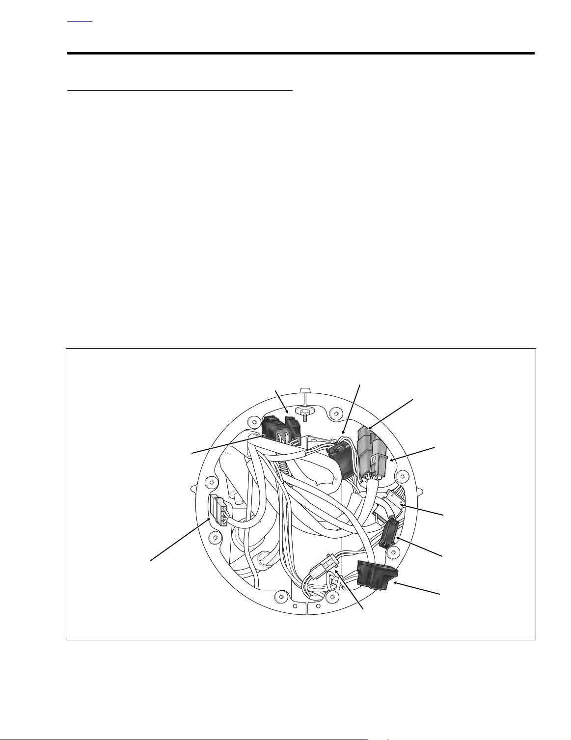
2. See Figure 8-149. Disconnect main harness from interconnect harness as follows:
●
Main to interconnect harness connector [1], 12place Deutsch (black); T-stud at front of right fairing
bracket.
●
Main to interconnect harness connector [2], 12place Deutsch (gray); T-stud on right fairing support
brace.
Main to interconnect harness connector [15], 4-
●
place Packard (black); anchor in hole at bottom of
radio (right side).
Main to interconnect harness connector [156], 6-
●
place Deutsch (gray); T-stud on right fairing support
brace.
10 A
11 A
12
13
f2225x8x
1 Captures main harness, cruise roll-off switch conduit,
audio harness (FLHTCUI only) and frame backbone.
2 Captures ignition/EFI harness only. ANCHORED
3 Captures main harness and audio harness (FLHTCUI
only). ANCHORED
456 Captures main harness, audio harness (FLHTCUI only),
EFI/ignition harness, and conduit to fuel tank harness (all
models except FLHR/C/S). ANCHORED
78 Captures audio harness (FLHTCUI only) and upper frame
tube.
910 Captures main harness and audio harness (FLHTCUI
only). ANCHORED
11 Captures main harness, audio harness (FLHTCUI only),
fuel vapor vent tube and console pod or instrument
console conduit. ANCHORED
12 Captures main harness, audio harness (FLHTCUI only),
console pod or instrument console conduit and upper
frame tube.
13 Captures main harness, audio harness (FLHTCUI only),
console pod conduit (FLHTCUI only) and upper frame
tube.
.
.
5 A
6 A
Saddlebag
7
.
Guard
8
.
.
Figure 8-148. Cable Strap Locations
REMOVAL- FLHT/C/U (PART II)
1. Remove the outer fairing and windshield. See Section
2.29 UPPER FAIRING/WINDSHIELD (FLHT/C/U),
OUTER FAIRING/WINDSHIELD, REMOVAL.
3. See Figure 8-149. Disconnect ignition switch from main
harness. Disconnect radio antenna cable. Proceed as
follows:
Ignition switch connector [33], 4-place Packard
●
(black); anchor in hole at bottom of radio (center).
Radio antenna cable connector [51]; back of radio
●
(left side).
4. Remove screw to release main harness ground ring terminal and brake line P-clamp from front of upper fork
bracket.
5. Carefully pull main harness rearward under right side of
fairing cap allowing conduit and connectors to hang over
top of engine guard.
6. Remove screw, main harness ground ring terminal and
P-clamp to release main harness (and audio harness on
FLHTCU models) from right side of steering head.
7. Moving rearward, carefully cut
eleven
cable straps
securing main harness to frame backbone and right and
left frame tubes. See Figure 8-148. Carefully cut any
cable straps securing main harness to audio harness.
NOTE
Continue procedure at REMOVAL- ALL MODELS (PART III).
REMOVAL- ALL MODELS (PART III)
1. If cruise equipped, locate the cruise control roll-off
switch plumbed into the idle cable on right side of the
steering head. Push rubber boot on switch forward and
remove socket terminals from spade contacts.
2. Moving to left side of motorcycle, remove acorn nut to
release horn bracket from rubber mount stud. Pull elbow
terminals from spade contacts on horn and release conduit from J-clamp.
3. Remove flange nut (10 mm) from left side ground stud
on upper frame crossmember. Remove two main harness ground ring terminals. Repeat step to remove two
main harness ground ring terminals from right side
ground stud.See Figure 8-150.
2004 Touring: Electrical 8-117
Page 20

H
OME
Main to Interconnect
Harness [2]
Main to Interconnect
Harness [156]
Main to Interconnect
Harness [15]
f2238x8x
Main to Interconnect
Harness [1]
Ignition
Switch [33]
Figure 8-149. Inner Fairing - Main Harness Connectors (FLHTC/U)
4. Depress latches on maxi-fuse holder and then slide
cover rearward to disengage tongue from groove in fuse
block cover.
5. Moving to right side of motorcycle, pull back boot at top
of starter housing and remove flange nut and main
power cable ring terminal from post. Release cable from
clip anchored to T-stud at front of battery tray. Draw main
power cable to left side of motorcycle.
6. Carefully cut anchored cable strap to release fuse block
conduit from fuse block bracket. Pull fuse block from
tabs on bracket.
7. Remove the fuse block cover. Raise lipped side slightly
to disengage slots from tabs on fuse block.
8. If cruise equipped, lift the locking latch and remove
cruise module connector [17]. From inside battery box,
remove three flange bolts. Carefully pull cruise module
away from side of battery box exercising caution to avoid
losing grommets.
Radio Antenna
Cable [51]
9. Disconnect the rear fender lights connector [7], 8-place
Multilock, anchored at front of rear fender. Detach pin
housing from anchor.
10. Release ignition keyswitch and starter relays by pulling
anchors on rubber molding from holes in frame weldment at rear of battery box. Remove relays and molding
from connectors. Push connectors down into space
below frame weldment.
11. Locate the turn signal/security module inside hole of
frame weldment on opposite side. Depress tab at front of
spring clip and lift to release legs from holes in weldment. Remove module and disconnect 12-place Deutsch connector [30]. Push connector down into space
below frame weldment.
12. Pull rear fender lights, ignition keyswitch and starter
relays, and turn signal/security module conduit and connectors out through opening above rear of fuse block
bracket and allow to hang on left side of motorcycle.
8-118 2004 Touring: Electrical
Page 21

H
OME
13. Depending upon model, proceed as follows:
FLHR/C/S:
FLTR:
Move to step 14.
a. On left side of motorcycle, remove bolt (with flat
washer) to remove passenger seat strap and saddlebag front mounting bracket. Remove Phillips
screw and chrome frame tube cover.
b. Carefully cut cable strap to release radio antenna
cable from shoulder of upper frame tube (just in
front of air valve mounting bracket). Cut cable strap
to release radio antenna cable from slotted hole in
rear fender support.
c. At bottom of radio antenna bracket, rotate knurled
ring to separate pin and socket halves of radio
antenna cable connector [51].
d. Draw radio antenna cable forward to area of fuse
block bracket and allow to hang with other main harness branches.
FLHTC/U:
a. Open Tour-Pak and proceed as follows:
FLHTC:
f2250x8x
Remove rubber mat.
FLHTCU:
Open map pocket and remove acorn nuts
with flat washers. Remove map pocket and molded
liner from Tour-Pak.
b. Depress external latch and remove bulb socket from
left side of Tour-Pak.
c. Rotate knurled ring in a counterclockwise direction
to separate pin and socket halves of radio antenna
cable connector [51]. Release cable from two clips
at bottom of Tour-Pak.
d. On FLHTCU models, depress button and separate
pin and socket halves of Tour-Pak lights connector
[12], 3-place Multilock, inside Tour-Pak.
e. Pull grommet into Tour-Pak and remove from main
harness conduit.
f. Pull Tour-Pak lights and radio antenna cable con-
nectors through hole at front of Tour-Pak. Cut cable
strap to release conduit from luggage rack rail.
g. Draw Tour-Pak lights and radio antenna cable con-
nectors forward to area of fuse block bracket and
allow to hang with other main harness branches.
Remove flange nuts to release passenger hand rail,
if necessary.
Main Harness
Ground Ring
Terminals (2)
Main Harness
Ground Ring
Terminals (2)
Fuel Tank Harness
Connector [13]
Not Present on FLHR/C/S
B+ Connector [160]
Chassis
Ground Cable
Accessory
Connector [4]
Battery
Positive Cable
Battery
Negative Cable
Figure 8-150. Electrical Connectors - Upper Frame Cross Member (Under Seat)
2004 Touring: Electrical 8-119
Page 22

H
OME
Anchored Cable Strap
Captures Main Harness Conduit,
Neutral Switch Conduit and
Vehicle Speed Sensor Cable
f2276x8x
Battery
Box
See Figure 8-150.
6
Cable Strap
Captures Main Harness Conduit
and Frame Downtube
Captures Rear Brake Light Switch Wires
Cable Strap
and Lower Frame Tube
Cable Strap Anchor
Captures Main Harness Conduit
5
4
and Rear Brake Line
Figure 8-151. Cable Straps (Right Side View)
14. Cut anchored cable strap to release accessory connector [4] and B+ connector [160] from left side of frame
crossmember (in front of battery box). See Figure 8-150.
15. Cut cable strap to release vapor valve from mounting
bracket. Move vapor valve out of the way to facilitate harness removal.
16. Alternately feed branches of main harness hanging on
left side of motorcycle into battery box through opening
above front of fuse block bracket. For best results, feed
one length of conduit through at a time drawing the fuse
block through the opening last. Pulling branches out of
battery box, allow conduit and connectors to hang on left
side of frame backbone.
17. Moving to front right side of motorcycle, locate crankshaft position sensor connector [79], 2-place Mini-Deutsch, fixed to bracket at bottom of voltage regulator. Push
connector toward right side of motorcycle to disengage
small end of slot on attachment clip from T-stud on
bracket. Lift connector off T-stud. Depress button on
socket terminal side and pull apart pin and socket
halves.
18. Locate oil pressure sender at the front right side of the
crankcase. On FLHR/C/S models, pull elbow from post
of oil pressure switch. On FLHT/C/U and FLTR models,
pull external latch outward and use rocking motion to
remove Packard connector from oil pressure sender.
Cable Strap
Captures Main Harness Conduit,
Voltage Regulator Cables and
Lower Frame Tube
3
2
1
Cable Strap Anchor
Captures Main Harness Conduit,
Voltage Regulator Cables and
Rear Brake Line
19. Cut cable strap to free voltage regulator cables and main
harness conduit (leading to oil pressure sender and
crankshaft position sensor connectors) from inboard
side of rear brake pedal weldment. See Figure 8-151.
20. Cut cable straps from two anchors installed on T-studs at
top of lower frame tube.
21. Locate voltage regulator connector [77], 1-place Deutsch, just below the transmission exhaust bracket.
Depress external latch to separate pin and socket housings.
22. Depress external latch and pull solenoid connector from
top of starter housing.
23. Remove two elbow connectors from neutral switch
posts.
24. Pull two socket terminals from spade contacts on rear
brake light switch. Cut cable strap to free rear brake light
switch wires from lower frame tube.
25. Cut cable strap at rear of rear brake light switch bracket
to release main harness conduit from frame downtube.
26. Cut anchored
cable strap in hole of frame downtube
(inboard of rear swingarm bracket) to release vehicle
speed sensor cable, main harness and neutral switch
conduit.
8-120 2004 Touring: Electrical
Page 23

H
8319
8321
Rubber
Boot
OME
27. Pull ignition/EFI harness connector [8] from slot in electrical bracket. Depress external latches and separate pin
and socket halves.
28. Remove two flange nuts to release electrical bracket
from studs on side of battery box. Release security siren
connector and conduit from inboard side of electrical
bracket.
29. Pull ignition/EFI harness connector [8] and security siren
connector [142] and conduit into battery box through
opening at rear of frame crossmember.
30. Draw neutral switch wires out from under starter housing. For best results, move electrical bracket out of the
way and reach in under right side of battery box.
31. Carefully pull rear brake light switch, starter solenoid,
and neutral switch conduit and connectors rearward and
then feed up into battery box through same opening at
rear of frame crossmember. See Figure 8-152.
32. Note that main harness runs forward of the front battery
box TORX screw. Pull harness to the rear of the screw,
and then draw conduit and connectors out of battery box
and allow to hang on right side of frame backbone. See
lower frame of Figure 8-153.
Figure 8-152. Feed Harness Into Battery Box (Right Side)
CAUTION
Damage to wires can result in electrical problems. Be
sure that rubber boot is present on threaded end of battery box TORX screw. Replace rubber boot if absent or
damaged. See upper frame of Figure 8-153.
33. Remove main harness from motorcycle.
INSTALLATION- ALL MODELS (PART I)
NOTE
Disregard references to radio antenna cable and starter relay
connectors when working on FLHR/C/S models. The connectors are not part of the main harness on these motorcyles.
1. Position main harness on motorcycle as follows:
a. Lay main harness on frame backbone so that front
branches hang over top of right engine guard. On
FLHR/C/S models, front branches terminate in
headlamp and handlebar switch control connectors
(see Figure 8-146). On FLTR and FLHT/C/U models, front branches terminate in the ignition switch,
radio antenna cable and interconnect harness connectors (see Figure 8-149).
b. Adjust harness so that left and right side branches
split from main branch at location of anchor at center of frame backbone.
Figure 8-153. Battery Box TORX Screw (Right Side)
NOTE
If reusing the main harness, thread new cable strap through
eye in anchor and loosely capture main harness bundle. If
installing a new harness, remove and discard old anchor and
plug anchor attached to new harness into hole in center of
frame backbone.
Left Side
c. Locate left side branch terminating in rear fender
lights, ignition keyswitch and starter relays, turn signal/security module, fuse block, cruise module (if
equipped) and radio antenna cable connectors.
Feed connectors and conduit into battery box pulling branches out through opening above front of
fuse block bracket. Continue drawing harness out
through opening until two main harness ground ring
terminals are adjacent to left side ground stud on
frame crossmember.
2004 Touring: Electrical 8-121
Page 24

H
OME
d. Feed rear fender lights, ignition keyswitch and
starter relays, and turn signal/security module conduit and connectors through opening above rear of
fuse block bracket to area in front of rear fender.
NOTE
On FLTR and FLHT/C/U models, leave longer conduit of
radio antenna cable hanging outboard of fuse block bracket.
Right Side
e. Feed right side connectors and conduit into battery
box pulling voltage regulator, oil pressure sender
and crankshaft position sensor connectors and conduit out through opening at rear of frame crossmember. Feed connectors and conduit forward and
then downward following front of frame downtube.
Continue drawing harness out through opening in
side of battery box until two main harness ground
ring terminals are adjacent to right side ground stud
on frame crossmember.
2. Returning to left side of motorcycle, route horn conduit in
front of the top stabilizer link and then under the top
engine mounting bracket to back of horn. Install elbow
terminals onto horn spade contacts. Capture conduit in
J-clamp. Slide horn bracket onto rubber mount stud and
install acorn nut with flat washer. Tighten acorn nut to
80-100 in-lbs (9.0-11.3 Nm).
3. Slide two main harness ground ring terminals onto left
side ground stud on upper frame crossmember and
install flange nut (10 mm). Install chassis ground ring terminal onto right side ground stud and then two main harness ground ring terminals and flange nut (10 mm).
Tighten flange nuts to 50-90 in-lbs (5.7-10.2 Nm). See
Figure 8-150.
4. Mate pin and socket halves of rear fender lights connector [7], 8-place Multilock, and attach to anchor at front of
rear fender.
5. At front of rear fender, feed ignition keyswitch and starter
relay connectors up through rectangular shaped hole in
frame weldment. Fit relay connectors into rubber molding and install anchors on molding into holes in frame
weldment. Install relays in connectors.
6. Feed turn signal/security module connector [30] up
through hole on opposite side of frame weldment and
connect to module. Install module into hole in frame
weldment. Insert legs of spring clip into holes in weldment and push down until tab at front snaps in place.
7. If cruise equipped, install grommets into holes on left
side of battery box with the larger OD on the outboard
side. Align threaded holes on inboard side of cruise
module with holes in grommets and install flange bolts
from inside battery box. Alternately tighten flange bolts
to 60-96 in-lbs (6.8-10.9 Nm). Install cruise module connector [17] and engage locking latch.
8. Slide cover over fuse block until slots fully engage tabs
on block. Slide fuse block into position on mounting
bracket. Tabs on bracket fit into slots on each side of
fuse block cover. Install new anchored
hole at rear of fuse block bracket. Tighten cable strap to
capture fuse block conduit.
9. Route main power cable on maxi-fuse holder through
opening above front of fuse block bracket and then forward passing under frame crossmember toward right
side of motorcycle. Pull back boot at top of starter housing and install ring terminal on post. Install flange nut
and tighten to 70-90 in-lbs (7.9-10.2 Nm). Capture cable
in clip anchored to T-stud at front of battery tray.
10. Returning to left side of motorcycle, slide maxi-fuse
cover forward to engage tongue in groove of fuse block
cover and then insert maxi-fuse holder into cover until
latches engage.
11. Install new anchored
side of frame crossmember (in front of battery box).
Tighten cable strap to capture conduit of both accessory
connector [4] and B+ connector [160] approximately one
inch from connector housings. See Figure 8-150.
12. Hold vapor valve in position on left side of mounting
bracket. From right side of bracket, insert end of small
cable strap through hole in arm and then around body of
vapor valve. Mate ends of cable strap and pull tight
engaging strap in slot of arm. Cut any excess cable strap
material.
13. Depending upon model, proceed as follows:
FLHR/C/S: Move to step 14.
FLTR:
a. Feed radio antenna cable and connector rearward
following inboard side of upper frame tube. With the
3-place Multilock connector (unused) positioned
about as far rearward as the rear shock air valve,
install new cable strap to secure radio antenna
cable to shoulder of upper frame tube (just in front
of air valve mounting bracket). Using slotted hole,
install new cable strap to secure radio antenna
cable to rear fender support. See Figure 8-154.
b. At bottom of radio antenna bracket, rotate knurled
ring to mate pin and socket halves of radio antenna
cable connector [51].
c. Install chrome frame tube cover on frame tube.
Install Phillips screw. Install bolt (with flat washer) to
fasten saddlebag front mounting bracket and passenger seat strap to chrome frame tube cover.
cable strap in lower hole on left
cable strap in
8-122 2004 Touring: Electrical
Page 25

H
OME
1
9425
2
Figure 8-154. Capture Radio Antenna Cable (FLTR)
FLHTC/U:
a. Feed Tour-Pak lights and radio antenna cable con-
nectors and conduit through hole at front of TourPak. Capture cable and conduit in grommet. Install
grommet in hole with the larger OD facing inside.
b. Mate pin and socket halves of Tour-Pak lights con-
nector [12], 3-place Multilock, and tuck into cavity
inside Tour-Pak.
c. Rotate knurled ring in a clockwise direction to mate
pin and socket halves of radio antenna cable connector [51]. Capture cable in two clips at bottom of
To u r-Pak.
d. Install bulb socket on left side of Tour-Pak.
e. Loosely install new cable strap to secure main har-
ness conduit to luggage rack rail.
f. Proceed as follows:
FLHTC: Install rubber mat in Tour-Pak. Close TourPak.
FLHTCU: Install molded liner in Tour-Pak. Install
map pocket and secure using acorn nuts (with flat
washers). Close Tour-Pak.
14. Returning to right side of motorcycle, feed voltage regulator, oil pressure sender and crankshaft position sensor
connectors and conduit downward between rear swingarm and oil filler spout until free ends hang below lower
frame tube.
15. Route neutral switch wires under starter housing to
transmission top cover. For best results, move electrical
bracket out of the way and reach in under right side of
battery box. Install two elbow connectors onto posts of
neutral switch.
16. Snap solenoid connector to terminal at top of starter
housing.
17. Install new anchored
cable strap in hole of frame downtube (inboard of rear swingarm bracket) capturing vehicle speed sensor cable, main harness and neutral switch
conduit. See Figure 8-151.
18. Install new cable strap at rear of rear brake light switch
bracket capturing main harness conduit and frame
downtube. Cut any excess cable strap material.
19. Install two socket terminals onto spade contacts of rear
brake light switch. Install new cable strap to secure rear
brake light switch wires to lower frame tube.
20. Route branch of the main harness (terminating in the
voltage regulator, oil pressure sender and crankshaft
position sensor connectors) forward to front of motorcycle following inboard side of lower frame tube.
21. Mate pin and socket housings of voltage regulator connector [77], 1-place Deutsch, just below the transmission
exhaust bracket.
22. Position main harness conduit over two anchors
installed on T-studs at top of lower frame tube. Thread
new cable straps through eyelets in anchors to capture
conduit. Cut any excess cable strap material.
NOTE
In addition to the main harness conduit, rear cable strap
anchor also captures rear brake line, while front anchor captures rear brake line and voltage regulator cables.
23. Route main harness conduit inboard of rear brake pedal
weldment. Capturing main harness conduit and lower
frame tube, install new cable strap through opening in
rear brake pedal weldment. See Figure 8-151. Cut any
excess cable strap material.
NOTE
Cable strap also captures voltage regulator cables.
24. Route oil pressure sender and crankshaft position sensor connectors upward at rear of lower frame crossmember.
25. Mate pin and socket halves of crankshaft position sensor
connector [79]. Place large end of slot on attachment
clip over T-stud on bracket at bottom of voltage regulator.
Push connector toward left side of motorcycle to engage
small end of slot.
26. Install the oil pressure sender connector at the front right
side of the crankcase. On FLHR/C/S models, install
elbow connector on post terminal. On FLHT/C/U and
FLTR models, install 4-place Packard connector.
27. Returning to area of electrical bracket, feed ignition/EFI
harness connector [8] and security siren connector [142]
and conduit through opening to outboard side of battery
box.
2004 Touring: Electrical 8-123
Page 26

H
OME
28. Route siren connector and conduit on inboard side of
electrical bracket and install bracket on studs at side of
battery box. Install flange nuts on studs and tighten to
36-48 in-lbs (4.1-5.4 Nm).
29. Mate pin and socket halves of ignition/EFI harness connector [8]. Install connector into slot of electrical bracket.
30. Pull up on main harness and tuck conduit into space in
front of the battery box TORX screw (along with ignition/
EFI harness). See lower frame of Figure 8-153.
CAUTION
Damage to wires can result in electrical problems. Be
sure that rubber boot is present on threaded end of battery box TORX screw. Replace rubber boot if absent or
damaged. See upper frame of Figure 8-153.
31. At front of top engine stabilizer bracket, install new 14
inch cable strap capturing frame backbone and main
harness bundle. Tighten cable strap, but leave loose
enough so that one finger can be inserted between strap
and frame backbone. Do not overtighten. Cut any
excess cable strap material.
32. If cruise equipped, install cruise roll-off switch as follows:
a. Separate the cruise roll-off switch wires up to the
point where they enter the main harness conduit.
b. Orient the idle cable so that the spade contacts are
at the top.
c. Slide the insulators onto the switch spade contacts
(polarity is not a factor). For maximum insertion, be
sure that the external step on the insulators face
each other.
d. Fit the rubber boot over the cruise control roll-off
switch. An oval cut in the boot accommodates the
switch spade terminal connections.
NOTE
Depending upon model, continue procedure at INSTALLA-
TION- FLHR/C/S (PART II), INSTALLATION- FLTR (PART
II), or INSTALLATION- FLHT/C/U (PART II).
5. See Figure 8-146. Connect main harness as follows:
● Front fender tip lamp connector [32], 2-place Mul-
tilock (black); used on FLHR only.
● Passing lamps connector [73], 2-place Multilock
(white); used on FLHR/C only.
● Passing lamps switch connector [109], 4-place
Amp; used on FLHR/C only.
● Accessory switch connector [67], 4-place Amp.
● Right handlebar switch controls connector [22], 6-
place Deutsch (black); T-stud on fork stem nut lock
plate (left side).
● Cruise set/resume switch connector [159], 2-place
Deutsch (black); used on FLHRC only.
● Front turn signal lamps connector [31], 6-place Mul-
tilock; anchor in hole of fork stem nut lock plate (left
side).
● Left handlebar switch controls connector [24], 6-
place Deutsch (gray); T-stud on fork stem nut lock
plate (left side).
● Cruise on/off switch connector [158], 2-place Deut-
sch (gray); used on FLHRC only.
6. Install the wire connector at the back of headlamp bulb.
7. Align holes in headlamp housing with those in headlamp
nacelle (headlamp door bracket at bottom). Install the
eight Phillips screws.
8. Fit the square-shaped portion of the headlamp door
spring into the slot at the top of the headlamp housing
and then snap the headlamp door (chrome ring) into
place. Install Phillips screw at the bottom of the headlamp door and tighten to 9-18 in-lbs (1.0-2.0 Nm).
9. See Figure 8-147. Moving to inboard side of instrument
console, connect main harness as follows:
● Ignition/light key switch connector [33], 3-place
Packard.
● Indicator lights connector [21], 8-place Mini-Deut-
sch.
● Speedometer connector [39], 12-place Packard.
INSTALLATION- FLHR/C/S (PART II)
1. Install remaining cables straps as shown in Figure 8-
148.
2. Carefully feed main harness conduit and connectors forward under right side of instrument nacelle (keeping outboard of the front brake line).
3. Install P-clamp on main harness bundle. Install screw to
fasten P-clamp to right side of steering head.
4. Moving to front of motorcycle, reach inside headlamp
nacelle and install screw to fasten harness ground ring
terminal and brake line P-clamp to front of upper fork
bracket.
8-124 2004 Touring: Electrical
10. Slide odometer reset switch through hole in instrument
console and install rubber boot.
11. Bend flexible clamps on inboard side of instrument console as necessary to capture main harness conduit.
NOTE
Continue procedure at INSTALLATION- ALL MODELS
(PART III).
INSTALLATION- FLTR (PART II)
1. Install remaining cables straps as shown in Figure 8-
148.
Page 27

H
1WARNING1WARNING
OME
2. Install P-clamp on main harness bundle. Install two main
harness ground ring terminals onto screw and fasten Pclamp to right side of steering head.
3. Install the inner fairing. See Section 2.30 UPPER FAIR-
ING/WINDSHIELD (FLTR), INNER FAIRING, INSTAL-
LATION, steps 3-20.
NOTE
Continue procedure at INSTALLATION- ALL MODELS
(PART III).
INSTALLATION- FLHT/C/U (PART II)
1. Install remaining cables straps as shown in Figure 8-
148.
2. Install P-clamp on main harness (and audio harness on
FLHTCU models). Install main harness ground ring terminal onto screw and fasten P-clamp to right side of
steering head.
3. Moving to right engine guard, carefully feed main harness conduit and connectors forward under right side of
fairing cap to front of inner fairing.
4. Install screw to fasten harness ground ring terminal and
brake line P-clamp to front of upper fork bracket.
5. See Figure 8-149. Standing at front of motorcycle, mate
pin and socket halves of the following connectors and fix
positions using retaining devices:
● Main to interconnect harness connector [1], 12-
place Deutsch (black); T-stud at front of right fairing
bracket.
● Main to interconnect harness connector [2], 12-
place Deutsch (gray); T-stud on right fairing support
brace.
● Main to interconnect harness connector [15], 4-
place Packard (black); anchor in hole at bottom of
radio (right side).
● Main to interconnect harness connector [156], 6-
place Deutsch (gray); T-stud on right fairing support
brace.
6. See Figure 8-149. Connect ignition switch to main harness. Connect radio antenna cable. Proceed as follows:
● Ignition switch connector [33], 4-place Packard
(black); anchor in hole at bottom of radio (center).
● Radio antenna cable connector [51]; back of radio
(left side).
7. Install the outer fairing and windshield. See Section 2.29
UPPER FAIRING/WINDSHIELD (FLHT/C/U), OUTER
FAIRING/WINDSHIELD, INSTALLATION.
NOTE
Continue procedure at INSTALLATION- ALL MODELS
(PART III).
INSTALLATION- ALL MODELS (PART III)
1. Place battery in battery box, terminal side forward.
Rotate hold-down clamp so that lip (with rubber pad)
rests on edge of battery and tighten clamp bolt.
Always connect the positive battery cable first. If the
positive cable should contact ground with the negative
cable installed, the resulting sparks may cause a battery
explosion which could result in death or serious injury.
2. Insert bolt through battery positive cable (red) into
threaded hole of battery positive (+) terminal. Tighten
bolt to 60-96 in-lbs (6.8-10.9 Nm).
3. Insert bolt through battery negative cable (black) into
threaded hole of battery negative (-) terminal. Tighten
bolt to 60-96 in-lbs (6.8-10.9 Nm).
4. Align barbed studs in left side cover with grommets in
frame downtubes and push firmly into place (no tools
required).
5. Install left side saddlebag. See Section 2.25 SADDLE-
BAG, INSTALLATION.
6. Repeat steps 4-5 to install right side saddlebag and side
cover.
7. Install fuel tank. For carbureted models, see Section 4.7
FUEL TANK (CARBURETED), INSTALLATION (AFTER
COMPLETE REMOVAL), FLHT/C or FLHR/S. For fuel
injected models, see Section 9.4 FUEL TANK (FUEL
INJECTED), INSTALLATION (AFTER COMPLETE
REMOVAL), FLHT/C/U/I, FLTRI or FLHR/C/S/I.
FRAME GROUND STUD REPLACEMENT
1. Remove seat. See Section 2.24 SEAT, REMOVAL.
2. Locate threaded hole between ground studs. See Figure
8-155. Thoroughly scrape away all paint from around
threaded hole.
3. Moving to front of frame crossmember, thoroughly
scrape away all paint on face of threaded boss.
4. Obtain five parts shown in Figure 8-156.
5. Start hex screw into threaded boss and tighten to 90-120
in-lbs (10.2-13.6 Nm).
6. At rear of frame crossmember, install flat washer and
lockwasher onto threaded end of hex screw. Install hex
nut and tighten to 90-120 in-lbs (10.2-13.6 Nm).
2004 Touring: Electrical 8-125
Page 28

H
OME
Threaded Hole
f2250x8x
Figure 8-155. Remove Seat
Harness Ground
Ring Terminals
7. If replacing left side ground stud, slide two main harness
ground ring terminals onto hex screw. If replacing right
side ground stud, install chassis ground ring terminal
before the two main harness grounds.
8. Install jam nut onto hex screw and tighten to 50-90 in-
lbs (5.7-10.2 Nm).
9. Install seat. See Section 2.24 SEAT, INSTALLATION.
Frame
3
Crossmember
5
4
2
1. Hex Screw, 2551W
2. Flat Washer, 6703
3. Lock Washer, 7036
Figure 8-156. Install New Frame Ground Stud
4. Hex Nut, 7688
5. Jam Nut, 7689W
Boss
1
8-126 2004 Touring: Electrical
Page 29

H
f2254x8x
OME
INTERCONNECT HARNESS (FLHTCU)
REMOVAL
NOTE
When referencing inner fairing locations, the term “fairing
bracket” refers to either the left or right vertical support, while
the term “support brace” refers to either the left or right horizontal support. References to left and right always refers to
left and right side of motorcycle.
1. Remove maxi-fuse. See Section 8.3 SYSTEM FUSES,
MAXI-FUSE, REMOVAL.
2. Remove the outer fairing and windshield. See Section
2.29 UPPER FAIRING/WINDSHIELD (FLHT/C/U),
OUTER FAIRING/WINDSHIELD, REMOVAL.
3. Release anchors on convoluted tubing of interconnect
harness from lower outboard ears of speedometer and
tachometer brackets. See Figure 8-157. For best results,
squeeze anchor with needle nose pliers before pulling
from hole in ear.
4. Remove anchor on convoluted tubing of headlamp connector from hole in left fairing bracket. See Figure 8-160.
5. On opposite side of inner fairing, remove anchor on conduit of fairing cap switch connector from hole in lower
wing of right side radio support bracket. See Figure 8-
161.
6. Cut cable strap to release convoluted tubing of interconnect harness, conduit of main to interconnect harness
connectors [2] and [156], and housing of main to interconnect harness connector [1] from right fairing bracket.
See Figure 8-162.
7. Remove connectors from their retaining devices, if
present, and disconnect pin and socket halves. See Fig-
ure 8-158.
a. Main to interconnect harness connector [2], 12-
place Deutsch (gray); T-stud on right fairing support
brace (outboard side).
b. Main to interconnect harness connector [156], 6-
place Deutsch (gray); T-stud on right fairing support
brace (inboard side).
c. Radio connector [27], 23-place Amp (black); back of
radio (right side).
d. Indicator lamps [21]; 10-place Multilock (black);
above radio (between speedometer and tachometer
gauges).
e. Speedometer connector [39]; 12-place Packard
(black); back of speedometer. Unthread rubber boot
from odometer reset switch and pull switch from
hole in inner fairing.
f. Ta chometer connector [108]; 12-place Packard
(gray); back of tachometer.
Figure 8-157. Anchor Interconnect Harness in Lower
Ears of Speedometer/Tachometer Brackets
g. Ambient temperature sensor connector [107], if
present; 3-place Multilock (black); anchor in hole on
outboard side of left fairing bracket.
h. Left handlebar switch controls connector [24], 12-
place Deutsch (gray); T-stud on top of left fairing
support brace (inboard side).
i. Front turn signal connector [31], 6-place Multilock
(black); T-stud on top of left fairing support brace
(outboard side).
j. Main to interconnect harness connector [1], 12-
place Deutsch (black); T-stud at front of right fairing
bracket.
k. Main to interconnect harness connector [15], 4-
place Packard (black); anchor in hole at bottom of
radio (right side).
l. Fairing cap switch connector [105], 12-place Mul-
tilock (black); top of upper fork bracket (right side).
m. Right handlebar switch controls connector [22], 12-
place Deutsch (black); T-stud on fork stem nut lock
plate (left side).
n. Audio to interconnect harness connector [6], if
present; 3-place Deutsch (black); back of radio.
o. Passing lamps connector [73], 2-place Multilock
(white); below upper fork bracket (left side).
p. Front fender tip lamp connector [32], 2-place Mul-
tilock (black); below upper fork bracket (left side).
2004 Touring: Electrical 8-127
Page 30

H
OME
Main to Interconnect
Harness [156]
Main to Interconnect
Harness [2]
Main to Interconnect
Harness [15]
Tac hometer
Gauge [108]
Radio [27]
Indicator
Lamps [21]
Speedometer
Gauge [39]
Ambient
Temperature
Sensor [107]
Left Handlebar
Switch Controls [24]
Front Turn
Signals [31]
Main to Interconnect
Harness [1]
Fairing Cap
Switches [105]
f2238x8x
Figure 8-158. Inner Fairing - Interconnect Harness Connectors (FLHTC/U)
8. See Figure 8-159. Remove connectors from spade contacts as follows:
Left side:
● Left speaker
● Fuel gauge and lamp
● Cigarette lighter
Audio to Interconnect
Harness [6]
Front
Fender Tip [32]
Passing
Lamp [73]
Right Handlebar
Switch Controls [22]
9. Feed conduit (with orange tape) terminating in left side
speaker, fuel gauge, cigarette lighter and front turn signal connectors to mid section of inner fairing (area
between left and right fairing brackets). Also feed conduit
terminating in left handlebar switch controls connector
[24] to mid section.
8-128 2004 Touring: Electrical
Page 31

H
OME
f2238x8x
Gauge and Lamp
Right
Speaker
Oil Pressure
and Lamp
Fuel Gauge
and Lamp
Ambient
Temperature
Gauge and Lamp
Left
SpeakerVoltmeter Gauge
Cigarette
Lighter
Figure 8-159. Inner Fairing - Interconnect Harness Connectors (FLHTC/U)
10. Pull harness ground socket terminal from spade contact
fastened to top of upper fork bracket (left side).
11. See Figure 8-159. Remove connectors from spade contacts as follows:
Right side:
● Right speaker
● Voltmeter gauge and lamp
12. Feed conduit (with orange tape) terminating in right side
speaker and voltmeter gauge connectors to mid section
of inner fairing (area between left and right fairing brackets). Also feed conduit terminating in main to interconnect harness connectors [2] and [156] to mid section.
13. If present, remove connectors from spade contacts as
follows:
● Oil pressure gauge and lamp
● Ambient temperature gauge and lamp
14. Remove interconnect harness from motorcycle.
INSTALLATION
NOTE
When referencing inner fairing locations, the term “fairing
bracket” refers to either the left or right vertical support, while
the term “support brace” refers to either the left or right horizontal support. References to left and right always refers to
left and right side of motorcycle.
1. Center interconnect harness on top of radio. To verify
proper orientation, be sure that convoluted tubing (with
anchor) of headlamp connector is on left side of motorcycle, while conduit (with anchor) of fairing cap switch
connector is on the right.
2. Install anchors on convoluted tubing of interconnect harness into lower outboard ears of speedometer and
tachometer brackets. See Figure 8-157.
3. If present, install connectors onto spade contacts as follows:
● Oil pressure gauge and lamp
● Ambient temperature gauge and lamp
2004 Touring: Electrical 8-129
Page 32

H
OME
4. From mid section of inner fairing (area between left and
right fairing brackets), feed conduit (with orange tape)
terminating in left side speaker, fuel gauge, cigarette
lighter and front turn signal connectors behind left fairing
bracket to area of left support brace.
5. Install connectors onto spade contacts as follows:
Left side:
● Left speaker
● Fuel gauge and lamp
● Cigarette lighter; connect the orange/white wire
socket terminal to the socket spade contact, the
black wire socket terminal to the shell contact.
6. From mid section of inner fairing (area between left and
right fairing brackets), also feed conduit terminating in
left handlebar switch controls connector [24] behind left
fairing bracket to area of left support brace.
7. Push harness ground socket terminal onto spade contact fastened to top of upper fork bracket (left side).
8. From mid section of inner fairing, feed conduit (with
orange tape) terminating in right side speaker and voltmeter gauge connectors behind right fairing bracket to
area of right support brace.
9. Install connectors onto spade contacts as follows:
Right side:
● Right speaker
● Vol tmeter gauge and lamp
9421
Anchor
Figure 8-160. Anchor Convoluted Tubing of
Headlamp Connector
9423
Anchor
Oval Shaped
Hole
10. From mid section of inner fairing, also feed conduit terminating in main to interconnect harness connectors [2]
and [156] behind right fairing bracket to area of right support brace.
11. Mate pin and socket halves of the following connectors
and fix positions using retaining devices, if present:
a. Main to interconnect harness connector [2], 12-
place Deutsch (gray); T-stud on right fairing support
brace (outboard side).
b. Main to interconnect harness connector [156], 6-
place Deutsch (gray); T-stud on right fairing support
brace (inboard side).
c. Radio connector [27], 23-place Amp (black); back of
radio (right side).
d. Indicator lamps [21]; 10-place Multilock (black);
above radio (between speedometer and tachometer
gauges).
e. Speedometer connector [39]; 12-place Packard
(black); back of speedometer. Slide odometer reset
switch through hole in inner fairing and install rubber
boot.
Figure 8-161. Anchor Conduit of Fairing Cap
Switch Connector
9422
Cable
Strap
Figure 8-162. Cable Strap Convoluted Tubing, Conduit
and Connector to Fairing Bracket
8-130 2004 Touring: Electrical
Page 33

H
OME
f. Ta chometer connector [108]; 12-place Packard
(gray); back of tachometer.
g. Ambient temperature sensor connector [107], if
present; 3-place Multilock (black); anchor in hole on
outboard side of left fairing bracket.
h. Left handlebar switch controls connector [24], 12-
place Deutsch (gray); T-stud on top of left fairing
support brace (inboard side).
i. Front turn signal connector [31], 6-place Multilock
(black); T-stud on top of left fairing support brace
(outboard side).
j. Main to interconnect harness connector [1], 12-
place Deutsch (black); T-stud at front of right fairing
bracket.
k. Main to interconnect harness connector [15], 4-
place Packard (black); anchor in hole at bottom of
radio (right side).
l. Fairing cap switch connector [105], 12-place Mul-
tilock (black); top of upper fork bracket (right side).
m. Right handlebar switch controls connector [22], 12-
place Deutsch (black); T-stud on fork stem nut lock
plate (left side).
n. Audio to interconnect harness connector [6], if
present; 3-place Deutsch (black); back of radio.
o. Passing lamps connector [73], 2-place Multilock
(white); below upper fork bracket (left side).
p. Front fender tip lamp connector [32], 2-place Mul-
tilock (black); below upper fork bracket (left side).
13. On opposite side of inner fairing, install anchor on conduit of fairing cap switch connector into hole in lower
wing of right side radio support bracket. See Figure 8-
161.
14. Using oval shaped hole in right fairing bracket, install
new cable strap capturing convoluted tubing of interconnect harness, conduit of main to interconnect harness
connectors [15] and [156], and housing of main to interconnect harness connector [1]. See Figure 8-161 and
Figure 8-162.
15. Install the windshield and outer fairing. See Section 2.29
UPPER FAIRING/WINDSHIELD (FLHT/C/U), OUTER
FAIRING/WINDSHIELD, INSTALLATION.
16. Install maxi-fuse. See Section 8.3 SYSTEM FUSES,
MAXI-FUSE, INSTALLATION.
12. Install anchor on convoluted tubing of headlamp connector into hole in left fairing bracket. See Figure 8-160.
2004 Touring: Electrical 8-131
Page 34

H
OME
INTERCONNECT HARNESS (FLTR)
REMOVAL
1. Remove maxi-fuse. See Section 8.3 SYSTEM FUSES,
MAXI-FUSE, REMOVAL.
2. Place protective material on top of front fender to protect
paint from scratches or other damage.
3. Remove the outer fairing and windshield. See Section
2.30 UPPER FAIRING/WINDSHIELD (FLTR), OUTER
FAIRING, REMOVAL.
4. Carefully cut two cable straps and allow wire bundles
and conduit to hang naturally. See Figure 8-165.
Main to Interconnect
Harness [1]
Radio [27]
5. See Figure 8-163. Disconnect main harness from interconnect harness as follows:
● Main to interconnect harness connector [1], 12-
place Deutsch (black); below radio (right side).
● Main to interconnect harness connector [2], 12-
place Deutsch (gray); below radio (right side).
● Main to interconnect harness connector [15], 4-
place Packard (black); below radio (right side).
● Main to interconnect harness connector [156], 6-
place Deutsch (gray); below radio (right side).
6. See Figure 8-163. Disconnect handlebar switch controls
from interconnect harness. Disconnect radio and radio
ground. Proceed as follows:
Left Handlebar
Switch Controls [24]
Main to Interconnect
Harness [156]
Main to Interconnect
Harness [2]
Right Turn
Signal [31R]
Main to Interconnect
Harness [15]
Figure 8-163. Inner Fairing Connections (FLTR)
Right Handlebar
Switch Controls [22]
Radio
Ground
Left Turn
Signal [31L]
f2269x8x
8-132 2004 Touring: Electrical
Page 35

H
OME
f2219x8x
Indicator
Lamps [21]
Speedometer
Gauge [39]
Speaker
Switch [105]
Figure 8-164. Instrument Nacelle (Bezel Removed)
● Left handlebar switch controls connector [24], 12-
place Deutsch (gray); T-stud on left side of radio
bracket.
● Right handlebar switch controls connector [22], 12-
place Deutsch (black); T-stud on left side of radio
bracket.
NOTE
Push on each handlebar connector to disengage small end
of slot on attachment clip from T-stud on radio bracket. Lift
connector off T-stud.
● Radio connector [27], 23-place Amp (black); back of
radio (right side).
● Radio ground; single spade and socket terminal;
below radio (left side).
7. Remove left side of instrument nacelle. See Section 2.30
UPPER FAIRING/WINDSHIELD (FLTR), INSTRUMENT
NACELLE, REMOVAL, steps 1-6.
8. See Figure 8-164. Disconnect instrument nacelle
switches and ambient temperature sensor from interconnect harness as follows:
● Instrument nacelle switch connector [105], 12-place
Multilock.
● Ambient temperature sensor connector [107], 3-
place Multilock.
9. See Figure 8-164. Draw branches of interconnect harness (terminating in odometer reset switch and speedometer, tachometer, indicator lamps, instrument nacelle
switch and ambient temperature sensor connectors)
from instrument nacelle through tunnel of fairing bracket
Instrument Nacelle
Switches [105]
Tachometer
Gauge [108]
Ambient
Temperature
Sensor [107]
to front of inner fairing. Allow the interconnect harness to
hang along the left side of the front fender.
10. Remove connectors from spade contacts as follows:
Left side:
● Left speaker
● Fuel gauge and lamp
● Ambient temperature gauge and lamp
● Cigarette lighter
Right side:
● Right speaker
● Voltmeter gauge and lamp
● Oil pressure gauge and lamp
11. Free conduit of front turn signal lamp connectors [31L]
and [31R], 3-place Multilocks, from flexible clips on sides
of inner fairing.
12. Remove interconnect harness from motorcycle. Remove
radio antenna cable connector [51] at back of radio (left
side) to facilitate removal.
INSTALLATION
1. Center convoluted tubing of interconnect harness above
and inboard of hooks on radio bracket. See Figure 8-
165. To verify proper orientation, be sure that long length
2004 Touring: Electrical 8-133
Page 36

H
OME
9427
21
Figure 8-165. Cable Strap Convoluted Tubing
and Conduit
of conduit terminating in socket terminals of cigarette
lighter is on left side of motorcycle. Install radio antenna
cable connector [51] at back of radio (left side), if
removed.
2. Install connectors onto spade contacts as follows:
Left side:
● Left speaker
● Fuel gauge and lamp
● Ambient temperature gauge and lamp
● Cigarette lighter; connect the orange/white wire
socket terminal to the socket spade contact, the
black wire socket terminal to the shell contact.
Right side:
● Right speaker
● Vol tmeter gauge and lamp
● Oil pressure gauge and lamp
Left side:
● Left speaker
● Fuel gauge and lamp
Right side:
● Right speaker
● Vol tmeter gauge and lamp
3. Find branch of interconnect harness terminating in
odometer reset switch and speedometer, tachometer,
indicator lamps, instrument nacelle switch and ambient
temperature sensor connectors. Feed connectors and
conduit from front of inner fairing through tunnel of fairing bracket and then out through opening at top of fairing
bracket to instrument nacelle.
4. See Figure 8-164. Connect instrument nacelle switches
and ambient temperature sensor to interconnect harness as follows:
● Instrument nacelle switch connector [105], 12-place
Multilock.
● Ambient temperature sensor connector [107], 3-
place Multilock.
5. See Figure 8-163. Connect handlebar switch controls to
interconnect harness. Connect radio and radio ground.
Proceed as follows:
● Left handlebar switch controls connector [24], 12-
place Deutsch (gray); T-stud on left side of radio
bracket.
● Right handlebar switch controls connector [22], 12-
place Deutsch (black); T-stud on left side of radio
bracket.
NOTE
Place large end of slot on attachment clip over T-stud on
radio bracket and push on each handlebar connector to
engage small end of slot.
● Radio connector [27], 23-place Amp (black); back of
radio (right side).
● Radio ground; single spade and socket terminal;
below radio (left side).
6. See Figure 8-163. Connect main harness to interconnect harness as follows:
● Main to interconnect harness connector [1], 12-
place Deutsch (black); below radio (right side).
● Main to interconnect harness connector [2], 12-
place Deutsch (gray); below radio (right side).
● Main to interconnect harness connector [15], 4-
place Packard (black); below radio (right side).
● Main to interconnect harness connector [156], 6-
place Deutsch (gray); below radio (right side).
7. Orient connectors as shown in Figure 8-163. Install two
new cable straps outboard of fairing bracket hooks to
hold wire bundles together. Cut any excess cable strap
material. See Figure 8-165.
CAUTION
To avoid chafing wires of interconnect harness and possible damage to slots of outer fairing during installation,
verify that trim strips are installed on hooks of radio
bracket.
8. Capture conduit of front turn signal lamp connectors
[31L] and [31R], 3-place Multilocks, in flexible clips on
sides of inner fairing.
8-134 2004 Touring: Electrical
Page 37

H
OME
9. Install the outer fairing and windshield. See Section 2.30
UPPER FAIRING/WINDSHIELD (FLTR), OUTER FAIRING, INSTALLATION.
10. Install left side of instrument nacelle. See Section 2.30
UPPER FAIRING/WINDSHIELD (FLTR), INSTRUMENT
NACELLE, INSTALLATION, steps 5-7 and 9-10.
11. Install bezel. See BEZEL, INSTALLATION, in this sec-
tion.
12. Install maxi-fuse. See Section 8.3 SYSTEM FUSES,
MAXI-FUSE, INSTALLATION.
2004 Touring: Electrical 8-135
Page 38

H
OME
RADIO ANTENNA CABLE (FLHTC/U)
REMOVAL
1. Remove fuel tank. For carbureted models, see Section
4.7 FUEL TANK (CARBURETED), COMPLETE
REMOVAL, FLHT/C. For fuel injected models, see Section 9.4 FUEL TANK (FUEL INJECTED), COMPLETE
REMOVAL, FLHT/C/U/I, FLTRI.
2. Remove left side saddlebag. See Section 2.25 SAD-
DLEBAG, REMOVAL.
3. Gently pull side cover from frame downtubes (no tools
required).
4. Remove the outer fairing and windshield. See Section
2.29 UPPER FAIRING/WINDSHIELD (FLHT/C/U),
OUTER FAIRING/WINDSHIELD, REMOVAL.
5. Remove radio antenna cable connector [51] at back of
radio (left side). See Figure 8-166. Carefully cut cable
where it exits branch of main harness conduit.
6. Remove screw, ground wire ring terminal and P-clamp to
release main harness (and audio harness on FLHTCU)
from right side of steering head.
7. Carefully cut cable straps securing main harness to
frame backbone, left frame tube and luggage rack rail.
See Figure 8-169.
8. Open Tour-Pak and proceed as follows:
FLHTC: Remove rubber mat.
Cable
Clip
Cavity
Tour-Pak Lights
Connector [12]
Radio Antenna
Cable
Figure 8-167. Disconnect Tour-Pak Lights Connector
Tour-Pak
Hole
Grommet
f1466a2x
Radio Antenna
Cable Connector
Radio Antenna
Cable [51]
Figure 8-166. Remove Outer Fairing (FLHTC/U)
f2238x8x
Grommet
Cable
Clip
Figure 8-168. Feed Main Harness Thru Tour-Pak Hole
FLHTCU: Open map pocket and remove acorn nuts
(with flat washers). Remove map pocket and molded
liner from Tour-Pak.
9. Depress external latch and remove bulb socket from left
side of Tour-Pak.
10. Rotate knurled ring in a counterclockwise direction to
separate pin and socket halves of radio antenna cable
connector. Release cable from two clips at bottom of
To u r-Pak.
f1465a2x
8-136 2004 Touring: Electrical
Page 39

H
f2225x8x
1
4 A
5 A
6
7
Frame
Backbone
Saddlebag
Guard
1 Captures main harness, cruise roll-off switch conduit,
audio harness (FLHTCUI only) and frame backbone.
2 Captures main harness and audio harness (FLHTCUI
only). ANCHORED
.
34 Captures main harness and audio harness (FLHTCUI
only). ANCHORED
.
5 Captures main harness, audio harness (FLHTCUI only),
fuel vapor vent tube and console pod or instrument
console conduit. ANCHORED
.
6 Captures main harness, audio harness (FLHTCUI only),
console pod or instrument console conduit and upper
frame tube.
7 Captures main harness, audio harness (FLHTCUI only),
console pod conduit (FLHTCUI only) and upper frame
tube.
2 A
3 A
A = Anchored
OME
11. Depress button and separate pin and socket halves of
To ur-Pak lights connector [12], 3-place Multilock, inside
To ur-Pak. See Figure 8-167.
12. Pull grommet into Tour-Pak and remove from main harness conduit.
13. Pull Tour-Pak lights and radio antenna cable connectors
through hole at front of Tour-Pak. See Figure 8-168.
14. Carefully cut radio antenna cable where it exits main
harness conduit.
INSTALLATION
1. Place new radio antenna cable on motorcycle following
original routing. Note that the cable follows the branches
of the main harness (and audio harness on FLHTCU)
routed to the rear left side of the motorcycle.
NOTE
Specifically, from the front of the inner fairing, the radio
antenna cable is routed under the fairing cap where it passes
through a P-clamp on the right side of the steering head. The
cable then runs along the right side of the frame backbone,
where it crosses to the left side at the main harness anchor in
the center of the frame backbone. From this point, the cable
follows the left side of the frame backbone, runs along the
inboard side of the upper frame tube and then continues
down the luggage rack rail where it passes through the hole
at the front of the Tour-Pak.
2. Feed Tour-Pak lights and radio antenna cable connectors and conduit through hole at front of Tour-Pak. Capture conduit in grommet. Install grommet in hole with the
larger OD facing inside.
3. Mate pin and socket halves of Tour-Pak lights connector
[12], 3-place Multilock, and tuck into cavity inside TourPak. See Figure 8-167.
4. Rotate knurled ring in a clockwise direction to mate pin
and socket halves of radio antenna cable connector.
Capture cable in two clips at bottom of Tour-Pak.
5. Install bulb socket on left side of Tour-Pak.
6. Proceed as follows:
FLHTC: Install rubber mat in Tour-Pak. Close Tour-Pak.
FLHTCU: Install molded liner in Tour-Pak. Install map
pocket and secure using acorn nuts (with flat washers).
Close Tour-Pak.
7. At front of inner fairing, connect radio antenna cable
connector [51] to back of radio. See Figure 8-166.
8. On right side of motorcycle, capture radio antenna cable,
main harness and audio harness (if present) in P-clamp.
Install ground wire ring terminal on screw and fasten Pclamp to right side of steering head.
Figure 8-169. Install Cable Straps
9. At front of top engine stabilizer bracket, install new 14
inch cable strap capturing frame backbone, radio
antenna cable, main harness and audio harness (if
present). Tighten cable strap, but leave loose enough so
that one finger can be inserted between strap and frame
backbone. Do not overtighten. Cut any excess cable
strap material.
10. Install remaining cables straps as shown in Figure 8-
169.
2004 Touring: Electrical 8-137
Page 40

H
OME
11. Install the outer fairing and windshield. See Section 2.30
UPPER FAIRING/WINDSHIELD (FLTR), OUTER FAIRING, INSTALLATION.
12. Align barbed studs in left side cover with grommets in
frame downtubes and push firmly into place (no tools
required).
13. Install left side saddlebag. See Section 2.25 SADDLE-
BAG, INSTALLATION.
14. Install fuel tank. For carbureted models, see Section 4.7
FUEL TANK (CARBURETED), INSTALLATION (AFTER
COMPLETE REMOVAL), FLHT/C. For fuel injected
models, see Section 9.4 FUEL TANK (FUEL
INJECTED), INSTALLATION (AFTER COMPLETE
REMOVAL), FLHT/C/U/I, FLTRI.
8-138 2004 Touring: Electrical
Page 41

H
9425
2
1
OME
RADIO ANTENNA CABLE (FLTR)
REMOVAL
1. Remove fuel tank. See Section 9.4 FUEL TANK (FUEL
INJECTED), COMPLETE REMOVAL, FLHT/C/U/I,
FLTRI.
2. Remove left side saddlebag. See Section 2.25 SAD-
DLEBAG, REMOVAL.
3. Gently pull side cover from frame downtubes (no tools
required).
4. Remove the outer fairing and windshield. See Section
2.30 UPPER FAIRING/WINDSHIELD (FLTR), OUTER
FAIRING, REMOVAL.
5. Remove radio antenna cable connector [51] at back of
radio (left side). See Figure 8-170. Carefully cut cable
where it exits branch of main harness conduit.
6. Remove screw, ground wire ring terminal and P-clamp to
release main harness bundle from right side of steering
head.
7. Carefully cut cable straps securing main harness to
frame backbone and left frame tube. See Figure 8-172.
8. On left side of motorcycle, remove bolt (with flat washer)
to remove passenger seat strap and saddlebag front
mounting bracket. Remove Phillips screw and chrome
frame tube cover.
Radio Antenna
Cable [51]
Figure 8-170. Remove Outer Fairing (FLTR)
f2230x2x
Figure 8-171. Capture Radio Antenna Cable
9. Carefully cut cable strap to release radio antenna cable
from shoulder of upper frame tube (just in front of air
valve mounting bracket). Cut cable strap to release radio
antenna cable from slotted hole in rear fender support.
See Figure 8-171.
10. At bottom of radio antenna bracket, rotate knurled ring to
separate pin and socket halves of radio antenna cable
connector [51].
11. Draw radio antenna cable forward to area of fuse block
bracket. Carefully cut cable where it exits branch of main
harness conduit.
INSTALLATION
1. Place new radio antenna cable on motorcycle following
original routing. Note that the cable follows the branches
of the main harness routed to the rear left side of the
motorcycle.
NOTE
Specifically, from the front of the inner fairing, the radio
antenna cable is routed through an opening on the right side
of the fairing bracket where it then passes through a P-clamp
on the right side of the steering head. The cable runs rearward along the right side of the frame backbone, where it
crosses to the left side at the main harness anchor in the
center of the frame backbone. From this point, the cable follows the left side of the frame backbone, runs along the
inboard side of the upper frame tube and then down to the
radio antenna bracket.
2. Feed radio antenna cable and connector rearward following inboard side of upper frame tube. With the 3place Multilock connector (unused) positioned about as
far rearward as the rear shock air valve, install new
cable strap to secure radio antenna cable to shoulder of
2004 Touring: Electrical 8-139
Page 42

H
OME
upper frame tube (just in front of air valve mounting
bracket). Using slotted hole, install new cable strap to
secure radio antenna cable to rear fender support. See
Figure 8-171.
3. At bottom of radio antenna bracket, rotate knurled ring to
mate pin and socket halves of radio antenna cable connector [51].
4. Install chrome frame tube cover on frame tube. Install
Phillips screw. Install bolt (with flat washer) to fasten
saddlebag front mounting bracket and passenger seat
strap to chrome frame tube cover.
5. At front of inner fairing, connect radio antenna cable
connector [51] at back of radio (left side). See Figure 8-
170.
6. On right side of motorcycle, capture radio antenna cable
and main harness in P-clamp. Install ground wire ring
terminal on screw and fasten P-clamp to right side of
steering head.
7. At front of top engine stabilizer bracket, install new 14
inch cable strap capturing frame backbone, radio
antenna cable and main harness. Tighten cable strap,
but leave loose enough so that one finger can be
inserted between strap and frame backbone. Do not
overtighten. Cut any excess cable strap material.
8. Install remaining cables straps as shown in Figure 8-
169.
9. Install the outer fairing and windshield. See Section 2.30
UPPER FAIRING/WINDSHIELD (FLTR), OUTER FAIRING, INSTALLATION.
10. Align barbed studs in left side cover with grommets in
frame downtubes and push firmly into place (no tools
required).
11. Install left side saddlebag. See Section 2.25 SADDLE-
BAG, INSTALLATION.
12. Install fuel tank. See Section 9.4 FUEL TANK (FUEL
INJECTED), INSTALLATION (AFTER COMPLETE
REMOVAL), FLHT/C/U/I, FLTRI.
A = Anchored
Frame
Backbone
2 A
3 A
4 A
5 A
1
Saddlebag
6
7
f2225x8x
1 Captures main harness, cruise roll-off switch conduit,
2 Captures main harness and audio harness (FLHTCUI
34 Captures main harness and audio harness (FLHTCUI
5 Captures main harness, audio harness (FLHTCUI only),
6 Captures main harness, audio harness (FLHTCUI only),
7 Captures main harness, audio harness (FLHTCUI only),
audio harness (FLHTCUI only) and frame backbone.
only). ANCHORED
only). ANCHORED
fuel vapor vent tube and console pod or instrument
console conduit. ANCHORED
console pod or instrument console conduit and upper
frame tube.
console pod conduit (FLHTCUI only) and upper frame
tube.
.
.
.
Guard
8-140 2004 Touring: Electrical
Figure 8-172. Install Cable Straps
Page 43

H
f2192x8x
Console Pod
Connector [53]
OME
AUDIO HARNESS (FLHTCU)
REMOVAL
1. Remove fuel tank. For carbureted models, see Section
4.7 FUEL TANK (CARBURETED), COMPLETE
REMOVAL, FLHT/C. For fuel injected models, see Section 9.4 FUEL TANK (FUEL INJECTED), COMPLETE
REMOVAL, FLHT/C/U/I, FLTRI.
2. Remove right side saddlebag. See Section 2.25 SAD-
DLEBAG, REMOVAL.
3. Gently pull side cover from frame downtubes (no tools
required).
4. Repeat steps 2 and 3 on left side of motorcycle.
5. Remove the outer fairing and windshield. See Section
2.29 UPPER FAIRING/WINDSHIELD (FLHT/C/U),
OUTER FAIRING/WINDSHIELD, REMOVAL.
6. See Figure 8-173. Disconnect pin and socket halves of
the following connectors:
a. CB antenna cable connector [50], back of radio
(right side).
b. Audio to interconnect harness connector [6], 3-
place Deutsch (black); back of radio (right side).
c. Radio connector [28], 23-place Amp (gray); back of
radio (left side).
Interconnect Harness [6]
CB Antenna
Cable [50]
Audio to
Radio [28]
Figure 8-174. Disconnect Console Pod Connector
7. Remove screw, ground wire ring terminal and P-clamp to
release main harness and audio harness from right side
of steering head.
8. Carefully pull audio harness rearward under right side of
fairing cap allowing conduit and connectors to hang over
top of engine guard.
9. Carefully cut cable straps securing audio harness to
frame backbone, left and right frame tubes, and luggage
rack rails. See Figure 8-176. Carefully cut cable straps
securing audio harness to main harness, if present.
10. Release console pod connector [53], 12-place MiniDeutsch, from attachment clip anchored in hole at rear
of battery box. See Figure 8-174. Depress external
latches and use a rocking motion to separate pin and
socket halves.
11. Remove trim ring and gently pull on wire harness to
draw rear right speaker/passenger controls connector
[41], 6-place Mini-Deutsch, out of speaker box. Depress
external latch and use a rocking motion to separate pin
and socket halves.
12. Open Tour-Pak. Open map pocket and remove acorn
nuts. Remove map pocket and molded liner from TourPak.
Figure 8-173. Audio Harness Connectors
f2238x8x
13. Separate pin and socket halves of CB antenna cable
connector [50]. Release cable from clip at bottom of
Tour-Pak. See Figure 8-175.
14. Pull right side grommet into Tour-Pak and remove from
CB antenna cable. Feed CB antenna cable through hole
at front of Tour-Pak.
2004 Touring: Electrical 8-141
Page 44

H
OME
Grommet
Cable
Clip
a. CB antenna cable connector [50], back of radio
(right side).
b. Audio to interconnect harness connector [6], 3-
place Deutsch (black); back of radio (right side).
c. Radio connector [28], 23-place Amp (gray); back of
radio (left side).
3. On right side of motorcycle, capture audio harness and
main harness in P-clamp. Install ground wire ring terminal on screw and fasten P-clamp to right side of steering
head.
4. Mate pin and socket halves of console pod connector
[53], 12-place Mini-Deutsch. Install connector onto
attachment clip anchored in hole at rear of battery box.
See Figure 8-174.
CB Antenna
f1467b2x
Figure 8-175. Disconnect CB Antenna Cable Connector
15. Moving to opposite side of motorcycle, remove trim ring
and gently pull on wire harness to draw rear left speaker/
passenger controls connector [42], 6-place Mini-Deutsch, out of speaker box. Depress external latch and use
a rocking motion to separate pin and socket halves.
16. Release rear headset receptacle from bracket at bottom
of left side speaker box. Release spring from hole in
receptacle wire jacket.
17. Remove audio harness from motorcycle.
Cable Connector
INSTALLATION
1. Place new audio harness on motorcycle following original routing. Note that the audio harness follows the
branches of the main harness as it is routed to the rear
left and right sides of the motorcycle.
NOTE
Specifically, from the front of the inner fairing, the audio harness is routed under the fairing cap where it passes through
a P-clamp on the right side of the steering head. The harness
then runs along the right side of the frame backbone, where
a branch crosses to the left side at the main harness anchor
in the center of the frame backbone. From this point, each
branch follows its respective side of the frame backbone, running along the inboard side of the upper frame tubes and
then down the luggage rack rails.
2. See Figure 8-173. Standing at front of motorcycle, mate
pin and socket halves of the following wire harness connectors:
5. Mate pin and socket housings of rear right speaker/passenger controls connector [41], 6-place Mini-Deutsch.
Feed connector back up into speaker box pressing trim
ring into hole.
6. Pass CB antenna cable connector [50] through hole at
front of Tour-Pak. Capture cable in grommet. Install
grommet in hole with the larger OD facing inside. See
Figure 8-175.
7. Mate pin and socket halves of CB antenna cable connector. Capture antenna cable in clip at bottom of TourPak.
8. Moving to opposite side of motorcycle, mate pin and
socket housings of rear left speaker/passenger controls
connector [42], 6-place Mini-Deutsch. Feed connector
back up into speaker box pressing trim ring into hole.
9. Attach spring to rear headset receptacle using hole in
wire jacket. Capture headset receptacle in bracket at
bottom of left side speaker box.
10. At front of top engine stabilizer bracket, install new 14
inch cable strap capturing frame backbone, audio harness and main harness. Tighten cable strap, but leave
loose enough so that one finger can be inserted
between strap and frame backbone. Do not over-
tighten. Cut any excess cable strap material.
11. Install remaining cables straps as shown in Figure 8-
176.
12. Install the outer fairing and windshield. See Section 2.29
UPPER FAIRING/WINDSHIELD (FLHT/C/U), OUTER
FAIRING/WINDSHIELD, INSTALLATION.
13. Align barbed studs in right side cover with grommets in
frame downtubes and push firmly into place (no tools
required).
14. Install right side saddlebag. See Section 2.25 SADDLE-
BAG, INSTALLATION.
8-142 2004 Touring: Electrical
Page 45

H
OME
Frame
Backbone
2 A
15. Repeat steps 13 and 14 on left side of motorcycle.
A = Anchored
16. Install fuel tank. For carbureted models, see Section 4.7
FUEL TANK (CARBURETED), INSTALLATION (AFTER
1
COMPLETE REMOVAL), FLHT/C. For fuel injected
models, see Section 9.4 FUEL TANK (FUEL
INJECTED), INSTALLATION (AFTER COMPLETE
REMOVAL), FLHT/C/U/I, FLTRI.
8 A
9 A
10 A
11
12
f2225x8x
1 Captures main harness, cruise roll-off switch conduit,
audio harness (FLHTCUI only) and frame backbone.
2 Captures main harness and audio harness (FLHTCUI
only). ANCHORED
345 Captures main harness, audio harness (FLHTCUI only),
EFI/ignition harness, and conduit to fuel tank harness (all
models except FLHR/C/S). ANCHORED
67 Captures audio harness (FLHTCUI only) and upper frame
tube.
89 Captures main harness and audio harness (FLHTCUI
only). ANCHORED
10 Captures main harness, audio harness (FLHTCUI only),
fuel vapor vent tube and console pod or instrument
console conduit. ANCHORED
11 Captures main harness, audio harness (FLHTCUI only),
console pod or instrument console conduit and upper
frame tube.
12 Captures main harness, audio harness (FLHTCUI only),
console pod conduit (FLHTCUI only) and upper frame
tube.
.
.
3 A
4 A
5 A
Saddlebag
6
.
Guard
7
.
Figure 8-176. Install Cable Straps
2004 Touring: Electrical 8-143
Page 46

H
OME
CB ANTENNA CABLE (FLHTCU)
Grommet
REMOVAL
1. Remove fuel tank. For carbureted models, see Section
4.7 FUEL TANK (CARBURETED), COMPLETE
REMOVAL, FLHT/C. For fuel injected models, see Section 9.4 FUEL TANK (FUEL INJECTED), COMPLETE
REMOVAL, FLHT/C/U/I, FLTRI.
2. Remove right side saddlebag. See Section 2.25 SAD-
DLEBAG, REMOVAL.
3. Gently pull side cover from frame downtubes (no tools
required).
4. Remove the outer fairing and windshield. See Section
2.29 UPPER FAIRING/WINDSHIELD (FLHT/C/U),
OUTER FAIRING/WINDSHIELD, REMOVAL.
5. Locate CB antenna cable connector [50] at back of radio
(right side). Rotate knurled ring in a counterclockwise
direction to disconnect. See Figure 8-177. Carefully cut
cable where it exits audio harness conduit.
6. Remove screw, ground wire ring terminal and P-clamp to
release main harness and audio harness from right side
of steering head.
7. Carefully cut cable straps securing audio harness to
frame backbone, right frame tube and luggage rack rail.
See Figure 8-180. Carefully cut cable straps securing
audio harness to main harness, if present.
Cable
Clip
CB Antenna
f1467b2x
Figure 8-178. CB Antenna Cable Connector
8. Open Tour-Pak. Open map pocket and remove acorn
nuts (with flat washers). Remove map pocket and
molded liner from Tour-Pak.
9. Separate pin and socket halves of CB antenna cable
connector [50]. Release cable from clip at bottom of
To ur-Pak. See Figure 8-178.
Cable Connector
(Tour-Pak)
CB Antenna
Cable [50]
Figure 8-177. CB Antenna Cable Connector
(Inner Fairing)
f2238x8x
10. Pull right side grommet into Tour-Pak and remove from
CB antenna cable. Feed CB antenna cable through hole
at front of Tour-Pak.
11. Carefully cut CB antenna cable where it exits branch of
audio harness conduit.
INSTALLATION
1. Place new CB antenna cable on motorcycle following
original routing. Note that the cable follows the branches
of the main harness and audio harness routed to the
rear right side of the motorcycle.
NOTE
Specifically, from the front of the inner fairing, the CB
antenna cable is routed under the fairing cap where it passes
through a P-clamp on the right side of the steering head.
From this point, the cable follows the right side of the frame
backbone, runs along the inboard side of the upper frame
tube and then continues down the luggage rack rail where it
passes through the hole at the front of the Tour-Pak.
8-144 2004 Touring: Electrical
Page 47

f2225x8x
1
4 A
5 A
7
Frame
Backbone
Saddlebag
Guard
1 Captures main harness, cruise roll-off switch conduit,
audio harness (FLHTCUI only) and frame backbone.
2 Captures main harness and audio harness (FLHTCUI
only). ANCHORED
.
345 Captures main harness, audio harness (FLHTCUI only),
EFI/ignition harness, and conduit to fuel tank harness (all
models except FLHR/C/S). ANCHORED
.
67 Captures audio harness (FLHTCUI only) and upper frame
tube.
2 A
3 A
A = Anchored
6
H
OME
2. Pass CB antenna cable connector [50] through hole at
front of Tour-Pak. Capture cable in grommet. Install
grommet in hole with the larger OD facing inside. See
Figure 8-178.
3. Mate pin and socket halves of CB antenna cable con-
nector. Capture antenna cable in clip at bottom of TourPak.
4. Install two new cable straps to secure CB antenna cable
to rear right speaker/passenger controls conduit and luggage rack rail. See Figure 8-179.
5. Install molded liner in Tour-Pak. Install map pocket and
secure using acorn nuts (with flat washers). Close TourPak.
6. At front of inner fairing, rotate knurled ring to connect CB
antenna cable connector [50] to back of radio. See Fig-
ure 8-177.
7. On right side of motorcycle, capture CB antenna cable,
audio harness and main harness in P-clamp. Install
ground wire ring terminal on screw and fasten P-clamp
to right side of steering head.
8. At front of top engine stabilizer bracket, install new 14
inch cable strap capturing frame backbone, CB antenna
cable, audio harness and main harness. Tighten cable
strap, but leave loose enough so that one finger can be
inserted between strap and frame backbone. Do not
overtighten. Cut any excess cable strap material.
9. Install remaining cables straps as shown in Figure 8-
180.
10. Install the outer fairing and windshield. See Section 2.29
UPPER FAIRING/WINDSHIELD (FLHT/C/U), OUTER
FAIRING/WINDSHIELD, INSTALLATION.
9426
1
2
Figure 8-179. Secure CB Antenna Cable
Figure 8-180. Install Cable Straps
11. Align barbed studs in right side cover with grommets in
frame downtubes and push firmly into place (no tools
required).
12. Install right side saddlebag. See Section 2.25 SADDLE-
BAG, INSTALLATION.
13. Install fuel tank. For carbureted models, see Section 4.7
FUEL TANK (CARBURETED), INSTALLATION (AFTER
COMPLETE REMOVAL), FLHT/C. For fuel injected
models, see Section 9.4 FUEL TANK (FUEL
INJECTED), INSTALLATION (AFTER COMPLETE
REMOVAL), FLHT/C/U/I, FLTRI.
2004 Touring: Electrical 8-145
Page 48

H
OME
IGNITION HARNESS (CARBURETED)
REMOVAL
1. Remove fuel tank. See Section 4.7 FUEL TANK (CAR-
BURETED), COMPLETE REMOVAL, FLHT/C or
FLHR/S.
2. Unthread bolt and remove battery positive cable (red)
from battery positive (+) terminal. (Battery negative
cable already removed under FUEL TANK, COMPLETE
REMOVAL.)
3. Using a T40 TORX drive head, loosen bolt to move lip of
hold-down clamp off edge of battery. Remove battery
from battery box.
4. Remove right side saddlebag. See Section 2.25 SAD-
DLEBAG, REMOVAL.
5. Gently pull side cover from frame downtubes (no tools
required).
6. Carefully cut cable straps to free ignition harness from
right side of frame backbone, upper frame tube and
other wire harness bundles. See Figure 8-185.
7. Remove ignition coil connector [83] and manifold absolute pressure sensor connector [80]. Pull external latch
outward and use rocking motion to separate pin and
socket halves. Draw conduit and connectors to right side
of motorcycle as they are disconnected.
f1847x8x
1
2
1. Vehicle Speed Sensor [65]
2. P&A Security Siren [142]
Figure 8-182. Electrical Bracket (Inboard Side)
8. Remove ignition control module connector [10]. Depress
external latches and use a rocking motion to separate
pin and socket halves. See Figure 8-181.
9. Gently pull on data link connector [91] to disengage from
arms on electrical bracket.
Main Harness [8]
Data Link [91]
Ignition Control
Module [10]
Figure 8-181. Electrical Bracket (Under Right Side Cover)
f2191x8x
10. Pull main harness connector [8] from slot in electrical
bracket. Depress external latches and use a rocking
motion to separate pin and socket halves.
11. Remove two flange nuts to release electrical bracket
from studs on side of battery box.
12. On inboard side of electrical bracket, disconnect vehicle
speed sensor connector [65]. Depress button on socket
housing and pull apart pin and socket halves. See Fig-
ure 8-182.
CAUTION
Damage to wires can result in electrical problems. Be
sure that rubber boot is present on threaded end of battery box TORX screw. Replace rubber boot if absent or
damaged. See Figure 8-183.
13. Note that ignition harness conduit runs forward of the
front battery box TORX screw. Pull conduit to the rear of
the screw, and then draw connectors and conduit down
right side of frame backbone into battery box.
8-146 2004 Touring: Electrical
Page 49

H
f2226x8x
Main Harness
[8A]
Data Link
[91A]
Ignition
Control Module
[10B]
Vehicle Speed
Sensor [65B]
Ignition
Coil [83B]
Manifold Absolute
Pressure
Sensor [80B]
14. Pull connectors and conduit out through opening at side
OME
8321
Rubber
Boot
Figure 8-183. Remove Ignition Harness From Vehicle
of battery box to remove ignition harness from motorcycle.
INSTALLATION
1. Locate end of ignition harness terminating in two connectors. See Figure 8-184.
2. Standing on right side of motorcycle, carefully feed connectors and conduit through opening into battery box.
Pull up on harness and tuck conduit into space in front of
the battery box TORX screw.
Damage to wires can result in electrical problems. Be
sure that rubber boot is present on threaded end of battery box TORX screw. Replace rubber boot if absent or
damaged. See Figure 8-183.
3. Draw connectors and conduit up along right side of
frame backbone just below the main harness bundle.
4. Loosely install new cable straps to secure ignition harness to right side of frame backbone, upper frame tube
and other wire harness bundles. See Figure 8-185.
5. Feed ignition coil connector over the top engine stabilizer link to left side of motorcycle. Install ignition coil
connector [83] onto left side of ignition coil.
6. Install manifold absolute pressure sensor connector [80].
7. Returning to electrical bracket, mate pin and socket
halves of vehicle speed sensor connector [65]. Route
siren and vehicle speed sensor connectors and conduit
on inboard side of electrical bracket as shown in Figure
8-182.
CAUTION
Figure 8-184. Ignition Wire Harness Connectors
2004 Touring: Electrical 8-147
Page 50

H
OME
8. Slide electrical bracket onto studs at side of battery box.
Be sure that conduit is properly routed on inboard side of
electrical bracket or wires may be pinched during installation. Install flange nuts and tighten to 36-48 in-lbs
(4.1-5.4 Nm).
9. Install ignition control module connector [10].
A = Anchored
Frame
Backbone
10. Mate pin and socket halves of main harness connector
[8]. Install connector into slot of electrical bracket. See
Figure 8-181.
11. Verify that protective plug is installed in data link connector [91]. With the plug side down and in contact with tab,
position connector between arms on electrical bracket.
12. Tighten cable straps securing ignition harness to right
side of frame backbone, upper frame tube and other wire
harness bundles. Cut any excess cable strap material.
13. Place battery in battery box, terminal side forward.
Rotate hold-down clamp so that lip (with rubber pad)
rests on edge of battery and tighten clamp bolt.
1WARNING1WARNING
Always connect the positive battery cable first. If the
positive cable should contact ground with the negative
cable installed, the resulting sparks may cause a battery
explosion producing personal injury and/or property
damage.
14. Insert bolt through battery positive cable (red) into
threaded hole of battery positive (+) terminal. Tighten
bolt to 60-96 in-lbs (6.8-10.9 Nm).
15. Install fuel tank. See Section 4.7 FUEL TANK (CARBU-
RETED), INSTALLATION (AFTER COMPLETE
REMOVAL), FLHT/C or FLHR/S.
16. Align barbed studs in side cover with grommets in frame
downtubes and push firmly into place (no tools
required).
1 A
2 A
3 A
4 A
Saddlebag
Guard
f2225x8x
1 Captures ignition harness only. ANCHORED.
234 Captures main harness, audio harness (FLHTCUI only),
ignition harness and conduit to fuel tank harness (all
models except FLHR/C/S). ANCHORED
.
Figure 8-185. Remove/Install Cable Straps
17. Install right side saddlebag. See Section 2.25 SADDLE-
BAG, INSTALLATION.
18. Start motorcycle and verify proper operation without setting trouble codes.
8-148 2004 Touring: Electrical
Page 51

H
1. Vehicle Speed Sensor [65]
2. P&A Security Siren [142]
1
2
f2183x8x
OME
EFI HARNESS (FUEL INJECTED)
REMOVAL
1. Remove fuel tank. See Section 9.4 FUEL TANK (FUEL
INJECTED), COMPLETE REMOVAL, FLHT/C/U/I,
FLTRI, or FLHR/C/S/I.
2. Remove air cleaner and backplate. See Section 4.5 AIR
CLEANER, REMOVAL.
3. Unthread bolt and remove battery positive cable (red)
from battery positive (+) terminal. (Battery negative
cable already removed under FUEL TANK, COMPLETE
REMOVAL.)
4. Using a T40 TORX drive head, loosen bolt to move lip of
hold-down clamp off edge of battery. Remove battery
from battery box.
5. Remove right side saddlebag. See Section 2.25 SAD-
DLEBAG, REMOVAL.
6. Gently pull side cover from frame downtubes (no tools
required).
NOTE
Draw all EFI wire harness connectors to right side of motorcycle as they are disconnected.
7. Carefully cut five cable straps to free EFI wire harness
from right side of frame backbone, upper frame tube and
other wire harness bundles. See Figure 8-190.
[89A]
[87A]
[88A]
f2162x9x
[84A]
[85A]
[80A] Manifold Absolute Pressure Sensor
[84A] Front Fuel Injector
[85A] Rear Fuel Injector
[87A] Idle Air Control
[88A] Throttle Position Sensor
[89A] Intake Air Temperature Sensor
Figure 8-186. Induction Module Assembly (Top View)
Front
[80A]
Figure 8-187. Electrical Bracket (Inboard Side)
8. Remove idle air control connector [87] and manifold
absolute pressure sensor connector [80]. Pull external
latch(es) outward and use rocking motion to separate
pin and socket halves. See Figure 8-186.
9. Depress wire form to remove front fuel injector connector [84] and rear fuel injector connector [85].
10. Remove throttle position sensor connector [88] and
intake air temperature sensor connector [89].
11. Moving to left side of motorcycle, remove ignition coil
connector [83] from left side of ignition coil.
12. Pull back boot to reveal engine temperature sensor connector [90] at back of front cylinder. Pull external latch
outward and remove connector. Cut cable strap to
release conduit from horn bracket.
13. Returning to right side of motorcycle, depress external
latch and remove ECM connector [78].
14. Gently pull on data link connector [91] to disengage from
arms on electrical bracket.
15. Locate painted white dot on inboard side of fuse block
[119]. Pressing on dot, gently tug on conduit to release
tabs on fuse block from slots in bracket.
16. Pull main harness connector [8] from slot in electrical
bracket. Depress external latches and use a rocking
motion to separate pin and socket halves.
17. Remove two flange nuts to release electrical bracket
from studs on side of battery box.
2004 Touring: Electrical 8-149
Page 52

H
OME
8321
Rubber
Boot
8319
Figure 8-188. Remove EFI Harness From Vehicle
18. On inboard side of electrical bracket, disconnect vehicle
speed sensor connector [65]. Depress button on socket
housing and pull apart pin and socket halves. See Fig-
ure 8-187.
CAUTION
Damage to wires can result in electrical problems. Be
sure that rubber boot is present on threaded end of battery box TORX screw. Replace rubber boot if absent or
damaged. See upper frame of Figure 8-188.
19. Note that harness conduit runs forward of the front battery box TORX screw. Pull conduit to the rear of the
screw, and then draw sensor connectors and conduit
down right side of frame backbone into battery box.
20. Pull connectors and conduit out through opening at side
of battery box to remove harness from vehicle. See
lower frame of Figure 8-188.
INSTALLATION
1. Standing on right side of vehicle, carefully feed sensor
connectors and conduit through opening into battery
box. See lower frame of Figure 8-188. Pull up on harness and tuck conduit into space in front of the battery
box TORX screw.
CAUTION
Damage to wires can result in electrical problems. Be
sure that rubber boot is present on threaded end of battery box TORX screw. Replace rubber boot if absent or
damaged. See upper frame of Figure 8-183.
2. Draw sensor connectors and conduit up along right side
of frame backbone just below the main wire harness
bundle.
3. Loosely install five new cable straps to secure EFI wire
harness to right side of frame backbone, upper frame
tube and other wire harness bundles. See Figure 8-190.
4. Install front fuel injector connector [84] and rear fuel
injector connector [85]. See Figure 8-186.
5. Install manifold absolute pressure sensor connector [80]
and idle air control connector [87].
6. Install intake air temperature sensor connector [89] and
throttle position sensor connector [88].
7. Feed ignition coil and engine temperature sensor connectors to left side of vehicle, routing the first in front of
the top engine stabilizer link, the latter to the rear.
8. Install ignition coil connector [83] onto left side of ignition
coil.
9. Install engine temperature sensor connector [90] at back
of front cylinder. Pull boot over sensor to keep out dirt
and debris. Install new cable strap to secure connector
conduit to horn bracket.
10. Mate pin and socket halves of vehicle speed sensor connector [65].
11. Install security siren connector [142] and vehicle speed
sensor connector [65] on inboard side of electrical
bracket as shown in Figure 8-187. Be sure that conduit
and cables are properly routed or wires may be pinched
during installation.
12. Slide electrical bracket onto studs at side of battery box.
Install flange nuts and tighten to 36-48 in-lbs (4.1-5.4
Nm).
13. Mate pin and socket halves of main harness connector
[8]. Install connector into slot of electrical bracket.
14. Engage tabs on fuse block [119] with slots in electrical
bracket. Slide fuse block up into cavity. Gently tug on
conduit to verify that fuse block is locked in place.
15. Install ECM connector [78]. Push connector halves
together until latch clicks.
8-150 2004 Touring: Electrical
Page 53

H
OME
[78B]
[65B]
[8A]
Fuel Pump
Fuse
Spare
Fuse
ECM Power
Fuse
EFI System
Relay
[119B]
[89B]
[80B]
[88B]
[85B]
Rubber
Boot
[91A]
[90B]
[8A] Main Harness
[65B] Vehicle Speed Sensor
[78B] Electronic Control Module (ECM)
[80B] Manifold Absolute Pressure Sensor
[83B] Ignition Coil
[84B] Front Injector
[85B] Rear Injector
[87B] Idle Air Control
Figure 8-189. EFI Wire Harness Connectors
[88B] Throttle Position Sensor
[89B] Intake Air Temperature Sensor
[90B] Engine Temperature Sensor
[91A] Data Link
[119B] EFI Fuse Block
[84B]
[87B]
[83B]
f2224x9x
2004 Touring: Electrical 8-151
Page 54

H
OME
16. Verify that protective plug is installed in data link connector [91]. With the plug side down and in contact with tab,
position connector between arms on electrical bracket.
17. Tighten five cable straps securing EFI wire harness to
right side of frame backbone, upper frame tube and
other wire harness bundles. Cut any excess cable strap
material.
18. Place battery in battery box, terminal side forward.
Rotate hold-down clamp so that lip (with rubber pad)
rests on edge of battery and tighten clamp bolt.
A = Anchored
Frame
Backbone
1 A
1WARNING1WARNING
Always connect the positive battery cable first. If the
positive cable should contact ground with the negative
cable installed, the resulting sparks may cause a battery
explosion producing personal injury and/or property
damage.
19. Insert bolt through battery positive cable (red) into
threaded hole of battery positive (+) terminal. Tighten
bolt to 60-96 in-lbs (6.8-10.9 Nm).
20. See Section 9.4 FUEL TANK (FUEL INJECTED),
INSTALLATION (AFTER COMPLETE REMOVAL),
FLHT/C/U/I, FLTRI, or FLHR/C/S/I
21. Install backplate and air cleaner. See Section 4.5 AIR
CLEANER, INSTALLATION.
22. Align barbed studs in side cover with grommets in frame
downtubes and push firmly into place (no tools
required).
23. Install right side saddlebag. See Section 2.25 SADDLE-
BAG, INSTALLATION.
24. Start vehicle and verify proper operation without setting
trouble codes.
2 A
3 A
4 A
Saddlebag
Guard
f2225x8x
1 Captures EFI harness only (front injector, idle air control
234 Captures main harness, audio harness (FLHTCUI only),
and ignition coil conduit). ANCHORED
EFI harness and conduit to fuel tank harness (all models
except FLHR/C/S). ANCHORED
.
.
Figure 8-190. Remove/Install Cable Straps
8-152 2004 Touring: Electrical
 Loading...