

Page 1

2008 FLT Police Models Service Manual Supplement
99483-08SP
©2007 H-D.
Page 2

Harley-Davidson motorcycles conform to all applicable U.S.A. Federal Motor Vehicle Safety Standards
and U.S.A. Environmental Protection Agency regulations effective on the date of manufacture.
To maintain the safety, dependability, and emission and noise control performance, it is essential that
the procedures, specifications and service instructions in this manual are followed.
Any substitution, alteration or adjustment of emission system and noise control components outside of
factory specifications may be prohibited by law.
IMPORTANT NOTICE
Harley-Davidson Motor Company
Page 3

2008 FLT Police Models
Service Manual Supplement
©2007 H-D.
ALL RIGHTS RESERVED
99483-08SP
Printed in the U.S.A.
VISIT THE HARLEY-DAVIDSON WEB SITE
http://www.harley-davidson.com
Page 4

Blank Text Here
Page 5

Blank Text Here
READER COMMENTS
Please comment on the completeness, accuracy, organization, usability, and readability of this manual.
Please list the page, item, and part number(s) of any errors you find in this manual.
Please tell us how we can improve this manual.
Occupation:
Name: Dealership:
Street: Department:
City: State: Zip:
Please clip out and mail to:
Service Communications Department
Harley-Davidson Motor Company
P.O. Box 653
Milwaukee, WI USA 53201
The Harley-Davidson Service Communications Department maintains a continuous effort to improve the quality
and usefulness of its publications. To do this effectively, we need user feedback - your critical evaluation of
this manual.
2008 FLT Police Models Service Manual Supplement (99483-08SP)
Page 6

NOTES
Page 7

ABOUT THIS MANUAL
GENERAL
This Service Manual Supplement has been designed to be
used with the current Service Manual and has been prepared
with two purposes in mind. First, it will acquaint the user with
the construction of the Harley-Davidson product and assist in
the performance of basic maintenance and repair. Secondly,
it will introduce to the professional Harley-Davidson Technician
the latest field-tested and factory-approved major repair
methods.We sincerely believe that this Service Manual Supplement will make your association with Harley-Davidson
products more pleasant and profitable.
NOTE
This Service Manual Supplement provides information unique
to this model motorcycle. Any information not presented in this
supplement can be found in the appropriate Service Manual
or Electrical Diagnostic Manual.
HOW TO USE YOUR SERVICE MANUAL
SUPPLEMENT
Use the TABLE OF CONTENTS (which follows this FOREWORD) and the INDEX (at the back of this manual) to quickly
locate subjects. Sections and topics in this manual are
sequentially numbered for easy navigation.
CHAPTERNO.
Maintenance1
Chassis2
Engine3
Fuel System4
Electric Starter5
Drive6
Transmission7
Electrical8
Appendix A WiringA
Appendix B GlossaryB
For example, a cross-reference shown as 2.1 SPECIFICA-
TIONS refers to chapter 2 CHASSIS, heading 2.1 SPECIFICATIONS.
If the subject you seek is not in this supplement, refer to the
corresponding section in the appropriate Service Manual.
Check the title page located in the front of each section to find
the subject.
For quick and easy reference, all pages contain a section
number followed by a page number. For example, page 3-5
refers to page 5 in section 3.
In figure legends, the number following the name of a part
indicates the quantity necessary for one complete assembly.
PREPARATION FOR SERVICE
Stop the engine when refueling or servicing the fuel
system. Do not smoke or allow open flame or sparks near
gasoline. Gasoline is extremely flammable and highly
explosive, which could result in death or serious injury.
(00002a)
Good preparation is very important for efficient service work.
A clean work area at the start of each job will allow you to
perform the repair as easily and quickly as possible, and will
reduce the incidence of misplaced tools and parts. A motorcycle
that is excessively dirty should be cleaned before work starts.
Cleaning will occasionally uncover sources of trouble. Tools,
instruments and any parts needed for the job should be
gathered before work is started. Interrupting a job to locate
tools or parts is a distraction and causes needless delay.
NOTES
• To avoid unnecessary disassembly, carefully read all relative service information before repair work is started.
• In figure legends, the number which follows the name of
a part indicates the quantity necessary for one complete
assembly.
• When servicing a vehicle equipped with the HarleyDavidson Smart Security System (H-DSSS), you must
first disarm the security system. Either keep the fob in
close proximity to the vehicle, or use Digital Technician to
disable the security system while the vehicle is being serviced and re-enable the system after service is completed.
SERVICE BULLETINS
In addition to the information presented in this Service Manual
Supplement and the appropriate Service Manual, HarleyDavidson Motor Company will periodically issue Service Bulletins to Harley-Davidson dealers. Service Bulletins cover
interim engineering changes and supplementary information.
Consult the Service Bulletins to keep your product knowledge
current and complete.
USE GENUINE REPLACEMENT PARTS
Do not use aftermarket parts and custom made front forks
which can adversely affect performance and handling.
Removing or altering factory installed parts can adversely
affect performance and could result in death or serious
injury. (00001a)
To ensure satisfactory and lasting repairs, carefully follow the
Service Manual instructions and use only genuine HarleyDavidson replacement parts. Behind the emblem bearing the
words GENUINE HARLEY-DAVIDSON stand more than 100
years of design, research, manufacturing, testing and inspecting
experience.This is your assurance that the parts you are using
will fit right, operate properly and last longer.
FOREWORD
WARNINGS AND CAUTIONS
Statements in this service manual preceded by the following
words are of special significance.
I
Page 8

WARNING indicates a potentially hazardous situation
which, if not avoided, could result in death or serious
injury. (00119a)
CAUTION indicates a potentially hazardous situation
which, if not avoided, may result in minor or moderate
injury. (00139a)
CAUTION used without the safety alert symbol indicates
a potentially hazardous situation which, if not avoided,
may result in property damage. (00140a)
NOTE
Refers to important information, and is placed in italic type. It
is recommended that you take special notice of these items.
Proper service and repair is important for the safe, reliable
operation of all mechanical products.The service procedures
recommended and described in this service manual are
effective methods for performing service operations.
When reference is made in this manual to a specific brand
name product, tool or instrument, an equivalent product, tool
or instrument may be substituted.
Kent-Moore Products
All tools mentioned in this manual with an "HD", "J" or "B"
preface must be ordered through SPX K ent-Moore. For ordering
information or product returns, warranty or otherwise, visit
www.spx.com.
Loctite Sealing and Threadlocking Pr oducts
Some procedures in this manual call for the use of Loctite
products. If you have any questions regarding Loctite product
usage or retailer/wholesaler locations, please contact Loctite
Corp. at www.loctite.com.
PRODUCT REGISTERED MARKS
Allen, Amp Multilock, Bluetooth, Brembo, Delphi, Deutsch,
Dunlop, Dynojet, Fluke, G.E. Versilube, Gunk, Hydroseal,
Hylomar, Kevlar, Lexan, Loctite, Lubriplate, Keps, K&N, Magnaflux, Marson Thread-Setter Tool Kit, MAXI fuse, Molex, MPZ,
Mulitilock, Novus, Packard, Pirelli, Permatex, Philips, PJ1,
Pozidriv , Robinair , S100, Sems, Snap-on, Teflon, Threadlock er,
Torca, Torco, TORX, Tufoil, Tyco, Ultratorch, Velcro, X-Acto,
and XM Satellite Radio are among the trademarks of their
respective owners.
Always wear proper ey e protection when using hammer s,
arbor or hydraulic presses, gear pullers, spring compressors, slide hammers and similar tools. Flying par ts
could result in death or serious injury. (00496b)
Some of these service operations require the use of tools
specially designed for the purpose.These special tools should
be used when and as recommended. It is important to note
that some warnings against the use of specific service methods,
which could damage the motorcycle or render it unsafe, are
stated in this service manual. Howe v er, please remember that
these warnings are not all-inclusive. Inadequate safety precautions could result in death or serious injury.
Since Harley-Davidson could not possibly know, evaluate or
advise the service trade of all possible ways in which service
might be performed, or of the possible hazardous consequences of each method, we have not undertaken any such
broad evaluation. Accordingly, anyone who uses a service
procedure or tool which is not recommended by HarleyDavidson must first thoroughly satisfy himself that neither his
nor the operator's safety will be jeopardized as a result. F ailure
to do so could result in death or serious injury.
PRODUCT REFERENCES
H-D MICHIGAN, INC.TRADEMARK
INFORMATION
Harley, Harley-Davidson, H-D, Bar & Shield, Digital Tech,
Digital Technician, Destroyer, Deuce, Dyna, Electra Glide,
Evolution, F at Boy, Glaze, Gloss, H-D , H-Dnet.com, HD , Harley ,
Heritage Softail, Heritage Springer, Low Rider, Night Rod, Night
Train, Profile, Revolution, Road Glide, Road King, Rocker,
Softail, Sportster, Sun Ray, Sunwash, Tech Link, Twin Cam
88, Twin Cam 88B, Twin Cam 96, Twin Cam 96B, Twin Cam
103, Twin Cam 103B, Twin Cam 110, Twin Cam 110B, TourPak, Screamin' Eagle, Softail, Super Guide, Super Premium,
SYN3, Ultra Glide, V-Rod, VRSC, Wide Glide, and HarleyDavidson Genuine Motor Parts and Genuine Motor Accessories
are among the trademarks of H-D Michigan, Inc.
CONTENTS
All photographs, illustrations and procedures may not necessarily depict the most current model or component, but are
based on the latest production information available at the time
of publication.
Since product improvement is our continual goal, HarleyDavidson reserves the right to change specifications, equipment
or designs at any time without notice and without incurring
obligation.
Read and follow warnings and directions on all products.
Failure to follow warnings and directions can result in
death or serious injury. (00470b)
II FOREWORD
Page 9
MAINTENANCE
1.1 SCHEDULED MAINTENANCE
General...............................................................................1-1
CHASSIS
2.1 SPECIFICATIONS: CHASSIS
General...............................................................................2-1
2.2 VEHICLE IDENTIFICATION NUMBER
(V.I.N.)
General...............................................................................2-2
Manufacturing Tolerances...................................................3-1
3.2 SERVICE WEAR LIMITS
General...............................................................................3-2
3.3 OIL COOLER
Operation............................................................................3-3
Removal.............................................................................3-3
Cleaning and Inspection.....................................................3-4
Installation..........................................................................3-4
Oil Cooler Adapter and Thermostat Replacement..............3-4
Removal......................................................................3-4
Installation...................................................................3-4
FUEL SYSTEM
2.3 TIRES
General...............................................................................2-3
2.4 SEAT
General...............................................................................2-4
Seat Removal.....................................................................2-6
Seat Installation..................................................................2-6
Air Spring Replacement.....................................................2-6
Removal......................................................................2-6
Installation...................................................................2-6
Seat Bracket Mount Replacement......................................2-7
Removal......................................................................2-7
Installation...................................................................2-7
2.5 AIR SEAT RESERVOIR
Removal.............................................................................2-8
Installation..........................................................................2-9
2.6 SADDLEBAGS
Lockset.............................................................................2-11
Removal....................................................................2-11
Installation.................................................................2-11
Lockset Catch...................................................................2-11
Removal....................................................................2-11
Installation.................................................................2-11
Hinges..............................................................................2-11
Removal....................................................................2-11
Installation.................................................................2-12
Tether................................................................................2-12
Removal....................................................................2-12
Installation.................................................................2-12
Tether Brackets.................................................................2-12
Removal....................................................................2-12
Installation.................................................................2-12
Knob and Spring Latch.....................................................2-12
Removal....................................................................2-12
Installation.................................................................2-13
Spring Latch Bracket........................................................2-13
Removal....................................................................2-13
Installation.................................................................2-13
2.7 TACHOMETER BRACKET: FLHP/E
Removal...........................................................................2-14
Installation........................................................................2-15
ENGINE
4.1 FUEL SYSTEM
No Unique Content.............................................................4-1
ELECTRIC STARTER
5.1 ELECTRIC STARTER
No Unique Content.............................................................5-1
DRIVE
6.1 DRIVE
No Unique Content.............................................................6-1
TRANSMISSION
7.1 TRANSMISSION
No Unique Content.............................................................7-1
ELECTRICAL
8.1 BULB CHART
General...............................................................................8-1
8.2 SYSTEM FUSES AND RELAYS
System Fuses.....................................................................8-3
Removal......................................................................8-3
Installation...................................................................8-4
8.3 REAR MARKER LIGHTS
Marker Lights Replacement................................................8-5
Removal.............................................................................8-5
Installation..........................................................................8-5
8.4 HANDLEBAR SWITCHES
Horn and Siren Yelp Switch................................................8-6
Removal......................................................................8-6
Installation...................................................................8-6
Clutch Interlock Switch.......................................................8-7
Removal......................................................................8-7
Installation...................................................................8-7
Pursuit and Auxiliary Switch...............................................8-8
Removal......................................................................8-8
Installation...................................................................8-8
TABLE OF CONTENTS
3.1 SPECIFICATIONS: ENGINE
General...............................................................................3-1
8.5 AUTOMATIC COMPRESSION RELEASE
General.............................................................................8-10
Removal...........................................................................8-10
III
Page 10

TABLE OF CONTENTS
Installation........................................................................8-10
Compression Test.............................................................8-11
Diagnostics.......................................................................8-12
Diagnostic Tips..........................................................8-12
Diagnostic Notes.......................................................8-12
APPENDIX A WIRING
A.1 CONNECTORS
Connectors.........................................................................A-1
A.2 INDEX TO WIRING DIAGRAMS
Wiring Diagram Information...............................................A-7
Wire Color Codes........................................................A-7
Wiring Diagram Symbols............................................A-7
Wiring Diagrams.................................................................A-8
APPENDIX B GLOSSARY
B.1 GLOSSARY
Acronyms and Abbreviations..............................................B-1
REFERENCE MATERIAL
TOOLS...........................................................I
TORQUE VALUES.......................................III
INDEX...........................................................V
IV TABLE OF CONTENTS
Page 11

SUBJECT............................................................................................................................PAGE NO.
1.1 SCHEDULED MAINTENANCE.................................................................................................1-1
MAINTENANCE
Page 12

NOTES
Page 13

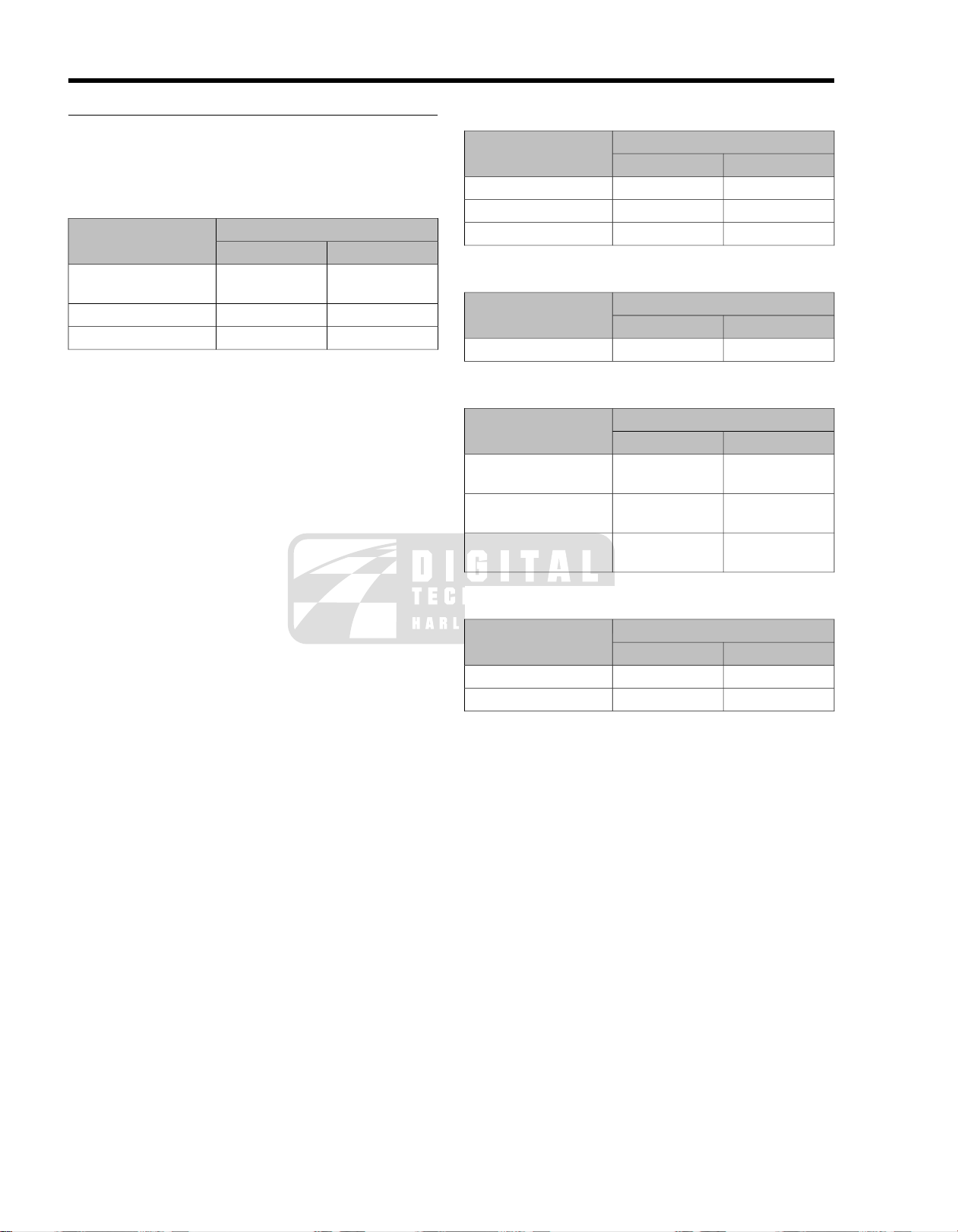
1.1SCHEDULED MAINTENANCE
GENERAL
The table below lists the maintenance requirements for police
motorcycles. If you are familiar with the procedures, refer to
the table for the recommended service interval. If necessary,
refer to the quick reference table (Table 1-2) for the required
Table 1-1. Regular Service Intervals: 2008 Touring Models
1000 MI.
1600 KM
Tires
sprocket
ators
switches
Air suspension
applicable)
bags
stablizers
Battery
Exhaust system
Road test
NOTES:
PROCEDUREITEM SERVICED
tread
and leakage
connections
loose or missing fasteners or
heat shields
system functions
1. Should be performed by an authorized Harley-Da vidson dealer , unless you hav e the proper tools, service data and are mechanically
qualified.
2. Disassemble, lubricate and inspect every 50,000 miles (80,000 kilometers).
3. Perform annually.
4. Change D.O.T. 4 and flush brake system every two years.
5. Perform at each rear tire change.
specifications. If more detailed information is needed, turn to
the Touring Models Service Manual for step-by-step instructions.
Various lubricants, sealants and greases are recommended
in certain service operations. Refer to Table 1-3 for the appro-
priate part numbers for these items.
5000 MI.
8000 KM
10,000 MI.
16,000 KM
15,000 MI.
24,000 KM
20,000 MI.
32,000 KM
XXXReplacePrimary chaincase lubricant
XXReplaceTransmission lubricant
XReplace
40,000 KM
XXXXXXReplaceEngine oil and filter
XXXXXXInspect, service as requiredAir cleaner
XXXXXXCheck pressure, inspect
XXXXXXInspect for wearBrake pads and discs
XXXXXInspectSpark plugs
XXXXXXCheck operationElectrical equipment and
XXXXXXLubricate hinges and latchesFuel door, Tour-Pak, saddle-
XXXXXXVerify component and
NOTES25,000 MI.
1XXXXXXInspect for leaksOil lines and brake system
1XXXCheck tightnessWheel spokes
1XXXXXXCheck adjustmentClutch
1XXXXXXInspect, adjust beltDrive belt and compensator
5Inspect for wearCompensator sprocket isol-
1XXXXXXCheck, adjust and lubricateBrake and clutch controls
1XXXXXXInspect and lubricateJiffy stand
1XXXXXXInspect for leaksFuel lines and fittings
1XReplaceFuel tank filter
4XXXXXXCheck levels and conditionBrake fluid
1, 2ReplaceFront fork oil
2XXXLubricateSteering head bearings
1XAdjust
1XXXXXXCheck pressure, operation
1XXInspectWindshield bushings (if
1XXXCheck tightnessCritical fasteners
1XXInspect, check tightnessEngine mounts and
3Check battery and clean
3XXXXXXInspect for leaks, cracks, and
2008 FLT Police Service: Maintenance 1-1
Page 14

Drive belt deflection
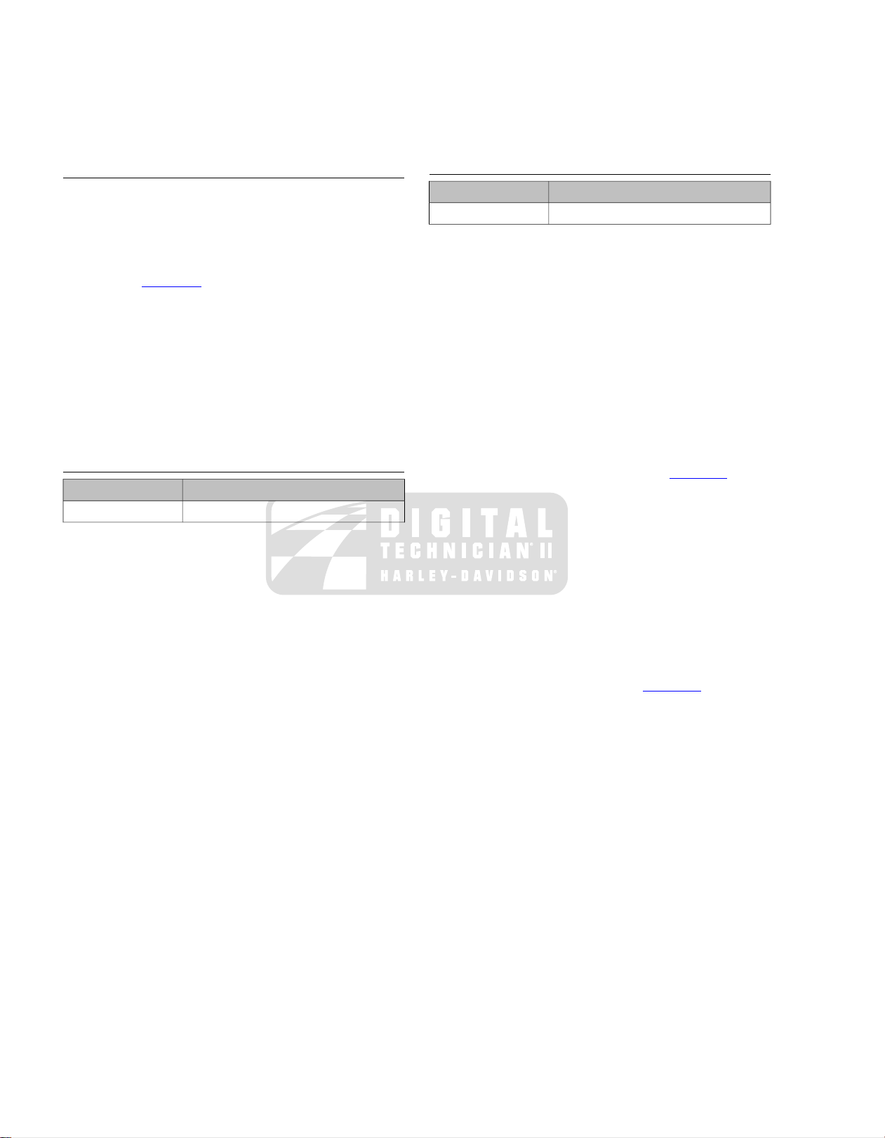
Table 1-2. Quick Reference Maintenance Chart: 2008 Police Models
DATASPECIFICATIONITEM SERVICED
14-21 ft-lbs (19.0-28.5 Nm)Drain plug torqueEngine oil and filter
4 qt. (3.8 L)Oil capacity
Hand tighten 1/2-3/4 turn after gasket contactFilter
63798-99AChrome filter part number
63731-99ABlack filter part number
Lubricant type and capacityPrimary chain lubricant
Lubricant levelTransmission lubricant
Lubricant type and capacity
Wear
strand
Air cleaner cover screw Threadlocker
Lubricant part numberClutch cable
FORMULA+ TRANSMISSION AND PRIMARY
CHAIN LUBRICATION (Part No. 99851-05)
Wet: 38 oz. (1124 ml)
Dry: 45 oz. (1331 ml)
14-21 ft-lbs (19.0-28.5 Nm)Primary chaincase drain plug torque
1/2-1 turnAdjuster screw free playClutch adjustment
72-120 in-lbs (8.1-13.6 Nm)Adjuster screw locknut torque
1/16-1/8 in. (1.6-3.2 mm)Free play at hand lever
84-108 in-lbs (9.5-12.2 Nm)Clutch inspection cover torque
Dipstick at FULL with motorcycle on jiffy stand and
filler plug resting on threads.
FORMULA+ TRANSMISSION AND PRIMARY
CHAIN LUBRICATION (Part No. 99851-05)
32 oz (0.95 liters)
14-21 ft-lbs (19.0-28.5 Nm)Transmission drain plug torque
25-75 in-lbs (2.8-8.5 Nm)Transmission filler plug/dipstick torque
Front: 36 psi (248 kPA)Pressure: solo riderTire pressure and wear
Rear: 36-40 psi (248-276 kPA)
Replace if less than 1/32 in. (0.8 mm) of tread
pattern
55 in-lbs (6.2 Nm) minimumSpoke nipple torqueWheel spokes
99953-99A (12 oz.)D.O.T. 4 hydraulic brake fluid part numberBrake fluid level
Front: 0.20 in. (5.0 mm)Fluid level (from top of master cylinder reservoir)
Rear: 0.26 in. (6.5 mm)
Front:7-10 in-lbs (0.8-1.1 Nm)Master cylinder reservoir cover screw torque
Rear: 12-15 in-lbs (1.4-1.7 Nm)
0.016 in. (0.4 mm)Minimum brake pad thicknessBrake pads and discs
75-102 in-lbs (8.5.-11.5 Nm)Brake caliper pad pin torque
Front: 0.18 in. (4.5 mm)Minimum brake disc thickness
Rear: 0.25 in. (6.3 mm)
0.008 in. (0.2 mm)Maximum brake disc lateral runout (warpage)
10 lb. (4.5 kg)Upward force applied at midpoint of bottom belt
3/8-7/16 in. (9.5-11.1 mm)FLHTP
1/4-5/16 in. (6.4-7.9 mm)FLHP/FLHPE
40-60 in-lbs (4.5-6.8 Nm)Air cleaner cover bracket screw torqueAir cleaner
36-60 in-lbs (4.1-6.8 Nm)Air cleaner cover screw torque
LOCTITE MEDIUM STRENGTH THREADLOCKER
243 (BLUE)
Part No. 99642-97 (6 ml)
LUBIT-8 SUPER OIL, Part No. 94968-85TV (1/4
fl. oz.)
35-45 in-lbs (4.0-5.1 Nm)Handlebar switch housing screw torque
1-2 2008 FLT Police Service: Maintenance
Page 15
Table 1-2. Quick Reference Maintenance Chart: 2008 Police Models
CCI #20 Brake Grease
Transmission and Primary Chaincase
Lubricant
Loctite Prism Primer (770)
Loctite Prism Superbonder (411)
Loctite Superbonder 420 Adhesive
DATASPECIFICATIONITEM SERVICED
HD-6R12TypeSpark plugs
0.038-0.043 in. (0.97-1.09 mm)Gap
12-18 ft-lbs (16.3-24.4 Nm)Torque
See FRONT FORK in the Touring Service Manual.AmountFront fork oil
HYDRAULIC FORK OIL (TYPE E)Type and part number
Part No. 99884-80 (16 oz.)
60-96 in-lbs (6.8-10.9 Nm)Terminal bolt torqueBattery
15-20 ft-lbs (20-27 Nm)Top caddy clamp screw torque
Table 1-3. Lubricants, Greases, Sealants
PACKAGEPART NUMBERITEM
1 oz squeeze tube98960-97Anti-Seize Lubricant
squeeze packet42830-05 (included in master cylinder
rebuild kit)
12 oz. bottle99953-99AD.O.T. 4 Brake Fluid
1 oz squeeze tube99861-02Electrical Contact Lubricant
1 qt bottle99851-05Genuine Harley-Davidson Formula+
squeeze packet42820-04G40M Brake Grease
1.9 oz squeeze tube99650-02Gray High Performance Sealant
3.5 oz tube99653-85HYLOMAR Gasket and Thread Sealant
6 ml squeeze tube99818-97Loctite Pipe Sealant With Teflon 565
6 ml squeeze tube99642-97Loctite Threadlocker 243 (blue)
6 ml squeeze tube94759-99Loctite Threadlocker 262 (red)
10 ml bottle98618-03Loctite Threadlocker 272
14 oz. cartridge99857-97Special Purpose Grease
1/4 fl. oz94968-85TVSuper Oil
16 oz bottle99884-80Type "E" Hydraulic Fork Oil
2008 FLT Police Service: Maintenance 1-3
Page 16

NOTES
1-4 2008 FLT Police Service: Maintenance
Page 17

SUBJECT............................................................................................................................PAGE NO.
2.1 SPECIFICATIONS: CHASSIS...................................................................................................2-1
2.2 VEHICLE IDENTIFICATION NUMBER (V.I.N.)..........................................................................2-2
2.3 TIRES........................................................................................................................................2-3
2.4 SEAT..........................................................................................................................................2-4
2.5 AIR SEAT RESERVOIR.............................................................................................................2-8
2.6 SADDLEBAGS........................................................................................................................2-11
2.7 TACHOMETER BRACKET: FLHP/E........................................................................................2-14
CHASSIS
Page 18

NOTES
Page 19
2.1SPECIFICATIONS: CHASSIS
GENERAL
Table 2-1. Capacities: 2008 Police Models
(approximate)
(drained)
(cover removed)
Table 2-2. Dimensions: 2008 Police Models
*With 180 lb. ( 81.7 kg) rider on seat.
Table 2-3.Weights: 2008 Police Models
FLHPFLHTPITEM
LITERSU.S.ITEM
22.76.0 galFuel tank (total)
3.81.0 galLow fuel warning lamp on
3.84.0 U.S. qt.Oil tank with filter
0.9532.0 fl. oz.Transmission
1.1238.0 fl. oz.Primary chaincase
1.3345.0 fl. oz.Primary chaincase
FLHPFLHTPITEM
MMIN.MMIN.
1612.963.51612.963.5Wheel base
238093.7238093.7Overall length
876.334.5990.639.0Overall width
129.55.1129.55.1Road clearance
1399.555.11549.461.0Overall height
693.427.3693.427.3Saddle height*
from factory
NOTE
Gross vehicle weight rating (GVWR) (maximum allowable
loaded vehicle weight) and corresponding gross axle weight
rating (GAWR) are printed on a label fix ed to the bottom of the
right front frame downtube.
NOTE
See 2.3 TIRES for important information regarding tire data
and tire inflation.
Table 2-4. Rear Air Suspension Pressures
SHOCK LOADING
RECOMMENDED
PRESSURES
KG.LB.KG.LB.
335739347764Weight as shipped
54412005441200GVWR
227500227500GAWR front
375827375827GAWR rear
kPa 0-241PSI 0-35
00Solo rider up to 150 lbs. (68 kg)
0-690-10Solo rider 150-200 lbs. (68-91 kg)
35-1035-15Solo rider 200-250 lbs. (91-113 kg)
138-24120-35At maximum GVWR
NOTE
Initial suspension fill pressure for a normally equipped police
motorcycle is 25 psi (172.4 kPa).
2008 FLT Police Service: Chassis 2-1
Page 20

2.2VEHICLE IDENTIFICATION NUMBER (V.I.N.)
1HD 1 FM M 1 3 8 Y 111000
1 2 3 4 5 6 7 8 9 10
om01103
GENERAL
See Figure 2-1. The full 17-digit serial number, or Vehicle
Identification Number (V.I.N.), is stamped on the right side of
the frame backbone at the rear of the steering head (and under
the main harness conduit). A label bearing the V.I.N. code is
also affixed to the left side of the steering head. An abbreviated
V.I.N. is stamped between the front and rear cylinders on the
left side of the crankcase.
Figure 2-1.Typical Harley-Davidson V.I.N.: 2008 Police Models
Sample V.I.N. as it appears on the steering head -
1HD1FHM137Y110000
Sample abbreviated V.I.N. as it appears on the crankcase -
FHM7110000
NOTE
Always give the complete V.I.N. when ordering parts or making
an inquiry about your motorcycle.
Table 2-5. Harley-Davidson V.I.N. Breakdown: 2008 Police Models
POSSIBLE VALUESDESCRIPTIONPOSITION
1=Originally manufactured for sale within the United StatesMarket designation1
5=Originally manufactured for sale outside of the United States
HD=Harley-DavidsonManufacturer2
1=Heavyweight motorcycle (901cc or larger)Motorcycle type3
See V.I.N. model tableModel4
M=Twin Cam 103™ 1690cc air-cooled, fuel injectedEngine type5
1=RegularIntroduction date6
2=Mid-year
3=California/regular
4=Cosmetic changes and/or special introductory date
5=California/cosmetic changes and/or special introductory date
6=California/mid-year
Can be 0-9 or XV.I.N. check digit7
8=2008Model year8
Y=York, PA U.S.A.Assembly plant9
VariesSequential number10
Table 2-6.V.I.N. Model Codes: 2008 Police Models
MODELCODE
FLHTPFM
FLHPFH
FLHPEFT
2-2 2008 FLT Police Service: Chassis
Page 21
2.3TIRES
GENERAL
The rear tire on FL police model motorcycles is fit for solo riding
only. If converted to a two-up bike, that is, configured for passenger use (with luggage), then the rear tire needs to be
changed to one with a higher weight rating. Since it has long
been Harley-Davidson policy not to mix different types of tires
on the same vehicle, we strongly recommend that both front
and rear tires be replaced. In order to alert the customer to this
safety issue, the f ollo wing w arning appears on a label fitted to
the rear fender approximately 1/4 inch (6.4 mm) behind the
domestic seat mounting hole.
This vehicle has tires with weight ratings for one person
operation. If this vehicle is modified to carry two people,
the tires must be changed. See a Harley-Davidson dealer
for proper replacement tires. Using improper tires can
cause tire failure which could result in death or serious
injury. (00096a)
Table 2-7.Tire Data
MANUFACTURER'S DESIGNATIONSIZETIRE LOCATION
All 2008 vehicles use only Dunlop Harley-Davidson tires.
NOTE
Use the tires recommended for civilian/pleasure vehicles of
the same year and model family.
Harley-Davidson front and rear tires are not the same.
Interchanging front and rear tires can cause tire failure,
which could result in death or serious injury. (00026a)
Tire size, manufacturer's description and inflation pressure are
listed below.
NOTE
ABS motorcycles must always use tires and wheels that are
the same as the original equipment. The ABS monitors the
rotational speed of the wheels through individual wheel speed
sensors. Changing to different diameter wheels or different
size tires can alter the rotational speed. This can upset the
calibration of the ABS and have an adv erse eff ect on its ability
to detect and prevent lockups. Tire inflation pressure that is
significantly low also can have an adverse effect.
TIRE PRESSURE
(COLD)
36 psi (248 kPa)Dunlop D402F PTMT90B 16 72HFront
36-40 psi (248-276 kPa)Dunlop D402 PTMT90B 16 72HRear
2008 FLT Police Service: Chassis 2-3
Page 22
GENERAL
1
3
2
om00451
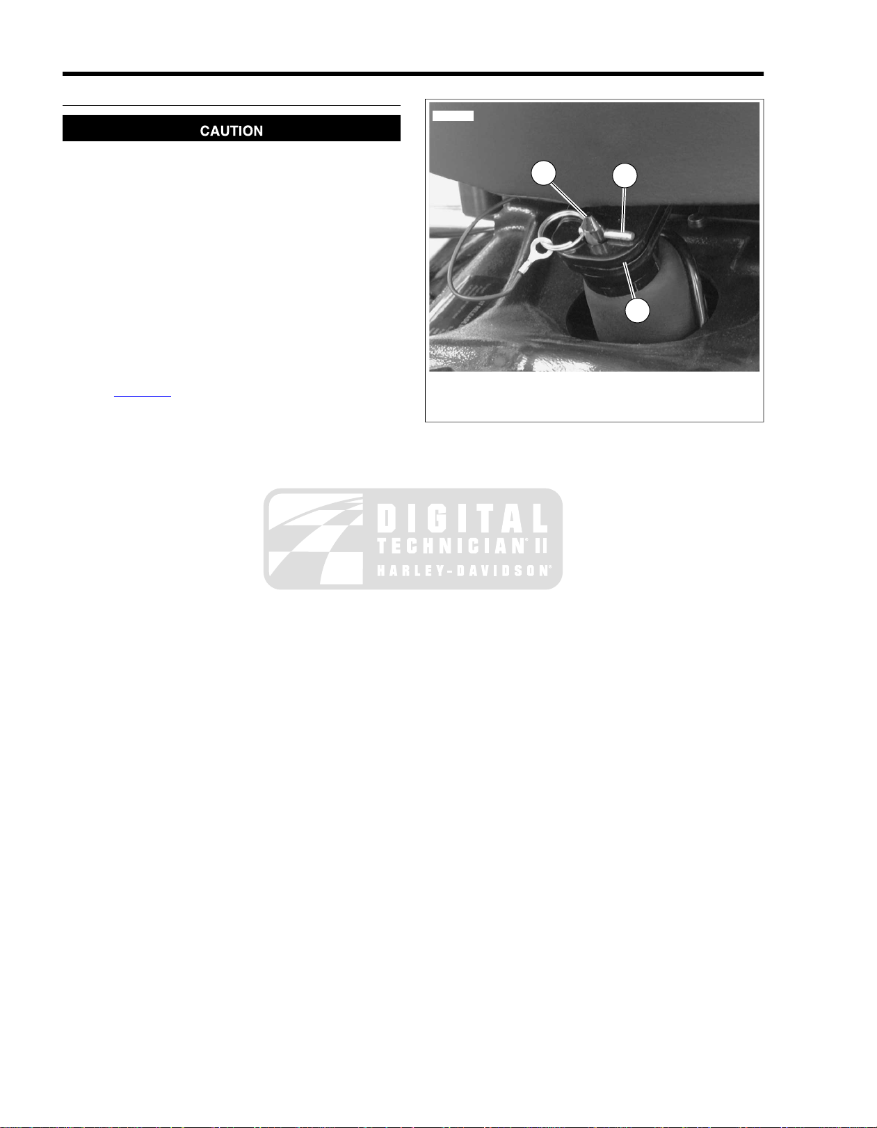
Maximum air pressure for the seat is 100 psi (689 kPa).
Normal air pressure is 30-45 psi (207-310 kPa). Do not
operate with air pressure so low that system bottoms out
on bumpy roads. (00167a)
NOTES
• Initially pressurize the seat air suspension system to 40
psi (275.8 kPa), then add or remov e pressure to the rider's
comfort. DO NO T oper ate motorcycle with system underinflated.
• T o chec k minimum air pressure, ha ve rider sit on seat and
bounce to simulate riding conditions. Visually check for
any contact between air spring and frame components.
Add air as necessary.
• See Figure 2-2. Removal and installation of retaining pin
(1) requires that the air pressure be removed from the seat
air suspension system. The seat will no longer pivot up
because the front of the seat will hit the fuel tank. Retaining
pin (1) should not be removed unless the seat is to be
removed.
• The seat does not adjust forward or rearward.
2.4SEAT
1. Retaining pin
2. Rear seat bracket
3. Support post
Figure 2-2. Seat Latch: Police Models
2-4 2008 FLT Police Service: Chassis
Page 23
1
2
3
4
5
7
6
8
11
12
10
13
14
17
18
19
22
20
23
21
15
16
9
sm04695
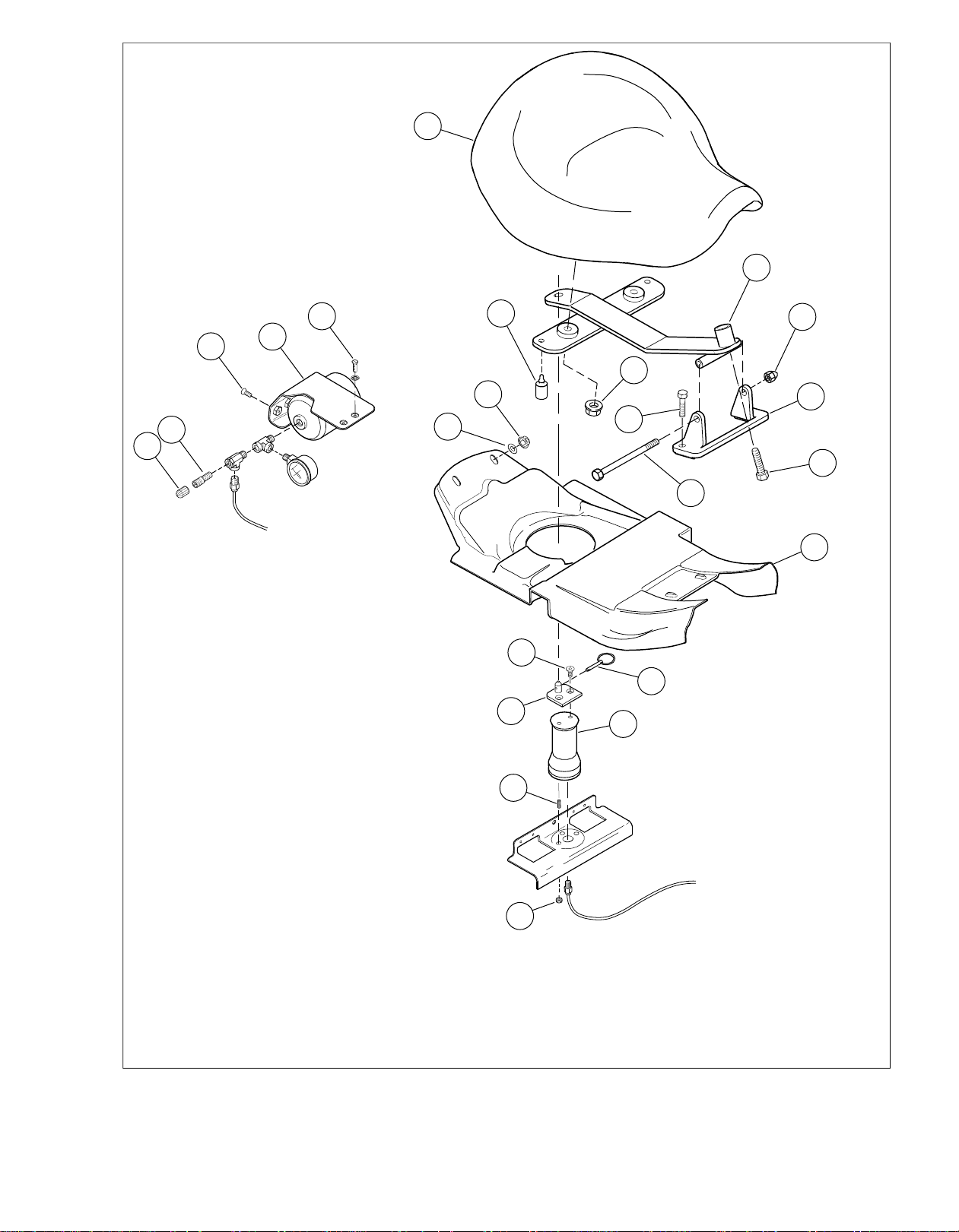
2. 18.10.Air fitting Retaining pinSeat bracket
5. 21.13.Fastener (2) Set screwAcorn Nut
8. 16.Rubber bumper (2) Pivot bolt
11.3. 19.Flange nut (2)Fastener (2) Air spring
14.6. 22.Seat bracket mountFlat Washer Top plate
Figure 2-3. Air Seat Assembly
17.9.1. Seat fairingSeatCap
20.12.4. Nut (2)Fastener (2)Air reservoir
23.15.7. FastenerHex scrweFlange nut (2)
2008 FLT Police Service: Chassis 2-5
Page 24
SEAT REMOVAL
sm04699
1. Remove air pressure from air spring and reservoir.
2. See Figure 2-2. Standing on left side of motorcycle , press
down on rear of seat and pull pin (1) from post (3) on top
plate.
3. See Figure 2-3. Remo ve front piv ot bolt (16) and n ut (13).
4. Lift seat and bracket assembly from motorcycle.
5. Remove two flange nuts (11) and he x screw (15) to release
seat from seat bracket (10).
6. Inspect two rubber bumpers (8) on seat bracket for cuts,
tears or general deterioration. If damaged, deteriorated or
missing, replace as follows:
a. Remove old rubber bumper and discard.
b. Moisten bead on new rubber bumper with soapy
water. Place rubber bumper into position at bottom
of seat bracket. Feed tail on bead up through hole in
seat bracket. Using a needle nose pliers, grasp tail
as close to bead as possible, and then pull bead up
through hole in seat bracket.
7. If necessary, remove two flange nuts (7) and washers (6)
and remove seat fairing (17) under seat.
SEAT INSTALLATION
Disconnect negative (-) battery cable first. If positive (+)
cable should contact ground with negative (-) cable connected, the resulting sparks can cause a battery explosion,
which could result in death or serious injury. (00049a)
2. Disconnect battery, negative (-) cable first.
3. Remove battery from battery box.
4. Remove air pressure from air spring and reservoir.
5. Depress collar on compression fitting and remove air tube
from air reservoir.
6. See Figure 2-3. Holding air spring to prevent twisting,
remove two fasteners (23) to release top plate (22) from
air spring (19).
7. Remove two flange nuts (20) under frame weldment (at
rear of battery box). Remove air spring from motorcycle.
1. See Figure 2-3. If removed, install seat fairing (17) under
seat. Tighten flange nuts (7) to 60-120 in-lbs (6.8-13.6
Nm).
2. Install seat onto seat bracket and start two flange nuts
(11). Align threaded hole in seat with hole in front of seat
bracket and start hex screw (15).
3. Tighten flange nuts to 96-144 in-lbs (10.9-16.3 Nm).
4. Tighten hex screw to 60-120 in-lbs (6.8-13.6 Nm).
5. Place seat and bracket assembly on motorcycle and install
front pivot bolt (16).Tighten nut (13) to 48-84 in-lbs (5.4-
9.5 Nm).
6. See Figure 2-2. Align post (3) on top plate with hole in rear
seat bracket.While pressing down on rear of seat, insert
pin (1) into post on top plate.
Maximum air pressure for the seat is 100 psi (689 kPa).
Normal air pressure is 30-45 psi (207-310 kPa). Do not
operate with air pressure so low that system bottoms out
on bumpy roads. (00167a)
7. Fill air reservoir to 40 psi (275.8 kPa), then add or remov e
pressure to the rider's comfort. Install protective cap on
air fitting.
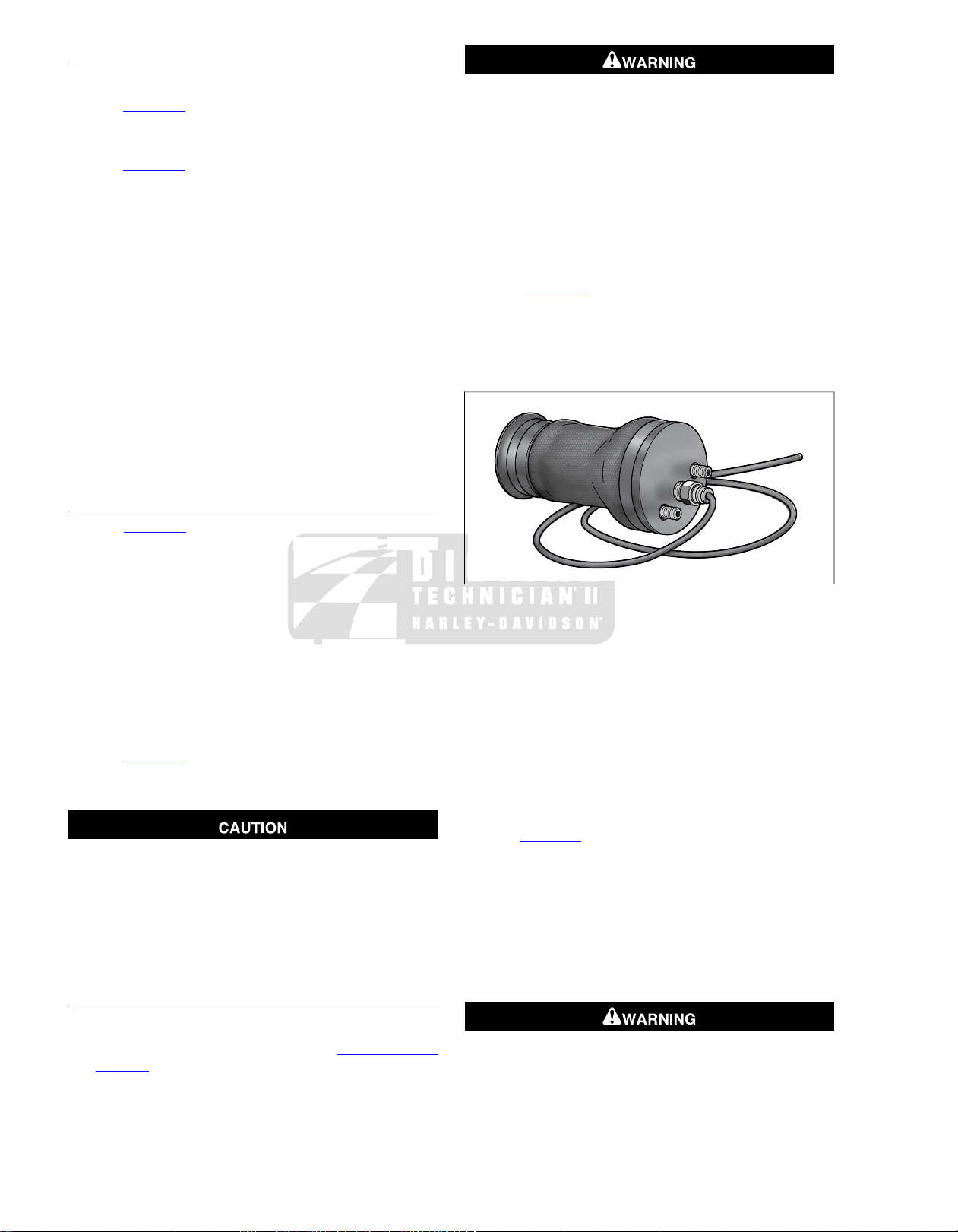
AIR SPRING REPLACEMENT
Figure 2-4. Air Spring Assembly
Installation
1. Feed air tube through large center hole in frame weldment
(at rear of battery box) and then route rearward following
inboard side of right upper frame tube to air reservoir.
2. Depress collar on compression fitting of air seat reservoir,
and insert air tube until it bottoms. Gently tug on tube to
verify that it is locked in place.
3. Connect air tube to compression fitting at bottom of air
spring, if removed.
4. See Figure 2-3. Place air spring on frame weldment while
engaging the two set screws.
5. Install two flange nuts (20) onto set screws (21).Tighten
flange nuts to 50-70 in-lbs (5.7-7.9 Nm).
6. Position top plate (22) onto air spring and start two
fasteners (23). Holding air spring to prevent twisting,
tighten screws to 36-60 in-lbs (4.1-6.8 Nm).
7. Place battery into battery box, terminal side forward.
Removal
1. Remove seat and seat fairing. See 2.4 SEAT, Seat
Removal.
2-6 2008 FLT Police Service: Chassis
Connect positive (+) battery cable first. If positive (+) cable
should contact ground with negative (-) cable connected,
the resulting sparks can cause a battery explosion, which
could result in death or serious injury. (00068a)
Page 25

8. Connect battery cables, positive (+) cable first.Tighten to
60-96 in-lbs (6.8-10.9 Nm).
9. Apply a light coat of petroleum jelly or ELECTRICAL
CONTACT LUBRICANT, Part No. 99861-02 (1 oz. tube),
to both battery terminals.
10. Install hold-down clamp so that the lip (with rubber pad)
rests on the edge of the battery.Tighten T40 T ORX screw
to 15-20 ft-lbs (20-27 Nm).
11. Install seat fairing.Tighten fasteners to 60-120 in-lbs (6.8-
13.6 Nm).
12. Install seat and inser t pin into post on top plate or air
spring. See 2.4 SEAT, Seat Installation.
Maximum air pressure for the seat is 100 psi (689 kPa).
Normal air pressure is 30-45 psi (207-310 kPa). Do not
operate with air pressure so low that system bottoms out
on bumpy roads. (00167a)
13. Fill air reservoir to 40 psi (275.8 kPa), then add or remov e
pressure to the rider's comfort. Install protective cap on
air valve.
SEAT BRACKET MOUNT REPLACEMENT
Removal
1. Remove seat. See 2.4 SEAT, Seat Removal.
2. See Figure 2-3. Remove two fasteners (12) to release
seat bracket mount from frame backbone.
Installation
1. Install seat bracket mount using two f asteners (12).Tighten
fasteners to 15-20 ft-lbs (20.3-27.1 Nm).
2. Install seat and insert pin into post on top plate of air
spring. See 2.4 SEAT, Seat Installation.
2008 FLT Police Service: Chassis 2-7
Page 26

REMOVAL
1
2
3
om00465
om00282
sm04700
1. Remove both saddlebags.
2. On the right side of the motorcycle, locate the air seat
reservoir air valve under the luggage rac k, and on the left
side, the rear shock air valv e just below the chrome frame
cover. See Figure 2-5 and Figure 2-6.
Use caution when bleeding air from the suspension.
Moisture combined with lubricant may leak onto the rear
wheel, tire and/or brake components and adversel y affect
traction, which could result in death or serious injury.
(00084a)
2.5AIR SEAT RESERVOIR
Figure 2-6. Rear Air Suspension Air Valve
1. Air reservoir
2. Air pressure gauge
3. Seat air valve
Figure 2-5. Seat Air Valve: Police Models
Figure 2-7. Raise Luggage Rack
3. Remove protective cap from each air valve and depress
pin to bleed air from both reservoir and shocks.To purge
rear air suspension lines of any oil, add 3-5 psi (20.7-34.5
kPa) before releasing air . Depress collar on each compression fitting and pull out air tube.
4. Remove bolt (with flat washer) to remov e saddlebag front
mounting bracket from chrome frame tube co ver . Remov e
2-8 2008 FLT Police Service: Chassis
Page 27

Phillips screw and chrome frame tube cover. Repeat step
sm04701
on opposite side of motorcycle.
5. At inboard side of rear marker lights bracket, carefully pull
left and right rear marker lights connectors.
6. Remove two hex bolts to free license plate bracket from
bottom support tube.
7. Remove T40 TORX screws (with spacers) on each side
of motorcycle to release ends of luggage rack from frame
tube weldments.
8. Raise luggage rack high enough to access air reservoir.
See Figure 2-7.
9. Remove two Phillips screws (with external tooth lockwashers) from mounting plate (pole lamp) at top of luggage
rack to release air reservoir bracket.
10. Remove two Phillips screws from license plate bracket to
free rear of air reservoir bracket. Be sure to hold reservoir
as the last screw is removed or damage to fender paint
can occur if assembly is dropped. See Figure 2-8.
11. Remove fittings and/or air pressure gauge from reservoir,
if necessary.
bracket. Alter nately tighten screws to 20-30 in-lbs (2.3-
3.4 Nm).
5. Place luggage rack into position inboard of frame tubes.
6. Install T40 TORX screws (with spacers) on each side of
motorcycle to secure ends of luggage rack to frame tube
weldments. Alternately tighten screws to 15-20 ft-lbs (20.3-
27.1 Nm).
7. Install two hex bolts to fasten license plate bracket to
bottom support tube. Alternately tighten screws to 15-20
ft-lbs (20.3-27.1 Nm).
8. At inboard side of rear marker lights bracket, connect left
and right rear marker lights connectors.
9. Install chrome frame tube cover on frame tube. Install
Phillips screw and tighten to 25-40 in-lbs (2.8-4.5 Nm).
Repeat step on opposite side of motorcycle.
10. Install bolt (with flat washer) to install saddlebag front
mounting bracket, but do not tighten. Repeat step on
opposite side of motorcycle.
11. Depress collar on compression fitting of air seat reservoir,
and insert air tube until it bottoms. Gently tug on tube to
verify that it is locked in place.
Figure 2-8. Air Seat Reservoir Assembly
INSTALLATION
TOOL NAMEPART NUMBER
HD-34633
1. Reassemble fittings and/or air pressure gauge onto air
reservoir, if remov ed. Orient parts as shown in Figure 2-8.
Apply PIPE SEALANT WITH TEFLON to threads before
assembly.
2. Position air reservoir beneath luggage rack exercising
caution to avoid scratching fender paint.
3. Slide two Phillips screws through holes in license plate
bracket engaging weld nuts at rear of air reservoir br acket.
Alternately tighten screws to 20-30 in-lbs (2.3-3.4 Nm).
4. Slide two Phillips screws (with external tooth lockwashers)
through holes in mounting plate (pole lamp) at top of luggage rack engaging weld nuts at top of air reservoir
AIR SUSPENSION PUMP AND
GAUGE
Maximum air pressure for the seat is 100 psi (689 kPa).
Normal air pressure is 30-45 psi (207-310 kPa). Do not
operate with air pressure so low that system bottoms out
on bumpy roads. (00167a)
12. Fill air reservoir to 40 psi (275.8 kPa), then add or remov e
pressure to the rider's comfort. Install protective cap on
air valve. See Figure 2-5.
NOTE
T o set minimum air pressure , have rider sit on seat and bounce
to simulate riding conditions. Visually check for any contact
between air spring and frame components. Add air as necessary.
13. Observe air pressure gauge. If leakage occurs, then
remove tube and inspect end for b urrs or damage. If either
condition is found, snip off end of tube and insert back into
fitting.
14. Depress collar on compression fitting of each shock and
insert air tube until it bottoms. Gently tug on tube to verify
that it is locked in place.
Do not exceed maximum air pressure for rear suspension.
Air components fill rapidly. Therefore, use low air line
pressure. Failure to do so may result in possible damage
to components. (00165a)
NOTE
Initial suspension fill pressure for a normally equipped police
motorcycle is 25 psi (172.4 kPa).
15. Fill shocks to 25 psi (172.4 kPa), then add or remove
pressure to the rider's comfort. Refer to Table 2-8.
2008 FLT Police Service: Chassis 2-9
Page 28
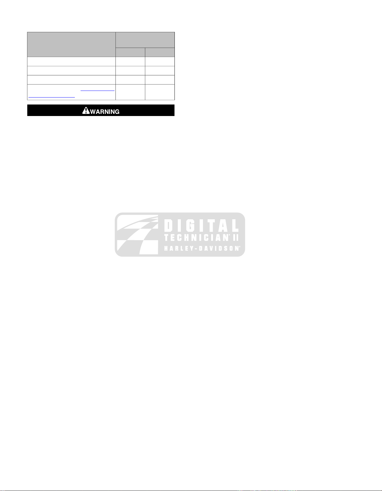
Table 2-8. Rear Air Suspension Pressures
SHOCK LOADING
ATIONS: CHASSIS)
Do not exceed the motorcycle's Gross Vehicle Weight
Rating (GVWR) or Gross Axle Weight Rating (GAWR).
Exceeding these weight ratings can affect stability and
handling, which could result in death or serious injury.
(00016e)
RECOMMENDED
PRESSURES
kPa 0-241PSI 0-35
00Solo rider up to 150 lbs. (68 kg)
0-690-10Solo rider 150-200 lbs. (68-91 kg)
35-1035-15Solo rider 200-250 lbs. (91-113 kg)
138-24120-35Maximum GVWR (see 2.1 SPECIFIC-
NOTE
An AIR SUSPENSION PUMP AND GAUGE (Part No. HD-
34633) is available at your Harley-Davidson dealer.
16. Observe air pressure gauge while filling. If leakage occurs,
remove tubes and inspect ends for burrs or damage. If
either condition is found, snip off end of tube and insert
back into fitting.
17. When air pressure remains constant, install protective cap
on air valve.
18. Install saddlebags. Tighten saddlebag front mounting
bracket bolts to 60-96 in-lbs (6.8-10.8 Nm).
2-10 2008 FLT Police Service: Chassis
Page 29
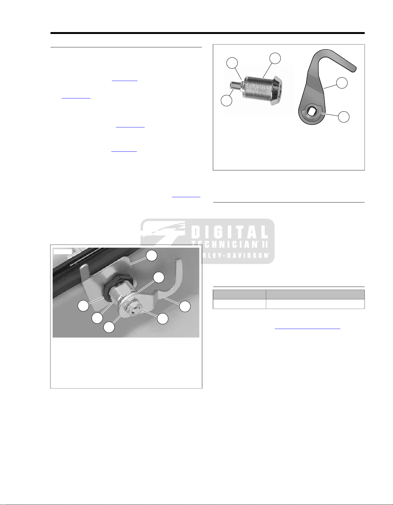
LOCKSET
1
4
5
7
6
3
2
sm03550
1
3
2
5
4
sm04804
Removal
1. At inside of saddlebag lid, remove hex nut, internal tooth
lockwasher, cam hook and cam washer. Remove jam nut
and lock guide. See Figure 2-9.
2. At outside of saddlebag lid, remove lockset. See
Figure 2-10.
Installation
1. With cam stop facing outboard side of saddlebag lid, install
lockset into hole. See Figure 2-10.
2. Install lock guide over threaded body of lockset oriented
with finger on inboard side of saddlebag lid and pointing
toward bottom. See Figure 2-9.
3. Install jam nut and tighten to 30-45 in-lbs (3.4-5.1 Nm).
4. Verify that groove in threaded stud of lockset is facing
inboard side of saddlebag lid. Use key to rotate threaded
stud, if necessary.
5. Align cam hook and cam washer as shown in Figure 2-10.
With the cam hook toward the outboard side of saddlebag
lid and cam washer on the inboard side, slide assembly
down threaded stud.
6. Install internal tooth lockwasher and hex nut onto threaded
stud.Tighten hex nut to 25-35 in-lbs (2.8-4.0 Nm).
2.6SADDLEBAGS
1. Lockset
2. Thin washer
3. Cam stop
4. Threaded stud
5. Cam washer
6. Cam hook
Figure 2-10. Lockset Mechanism
LOCKSET CATCH
Removal
1. Drill out two rivets using a 5/32 inch drill bit.
2. Remove backplate, lockset catch and flat washers.
Installation
1. Slide two new rivets through holes in backplate,
saddlebag, lockset catch and flat washers.
2. Compress rivets using a suitable rivet tool.
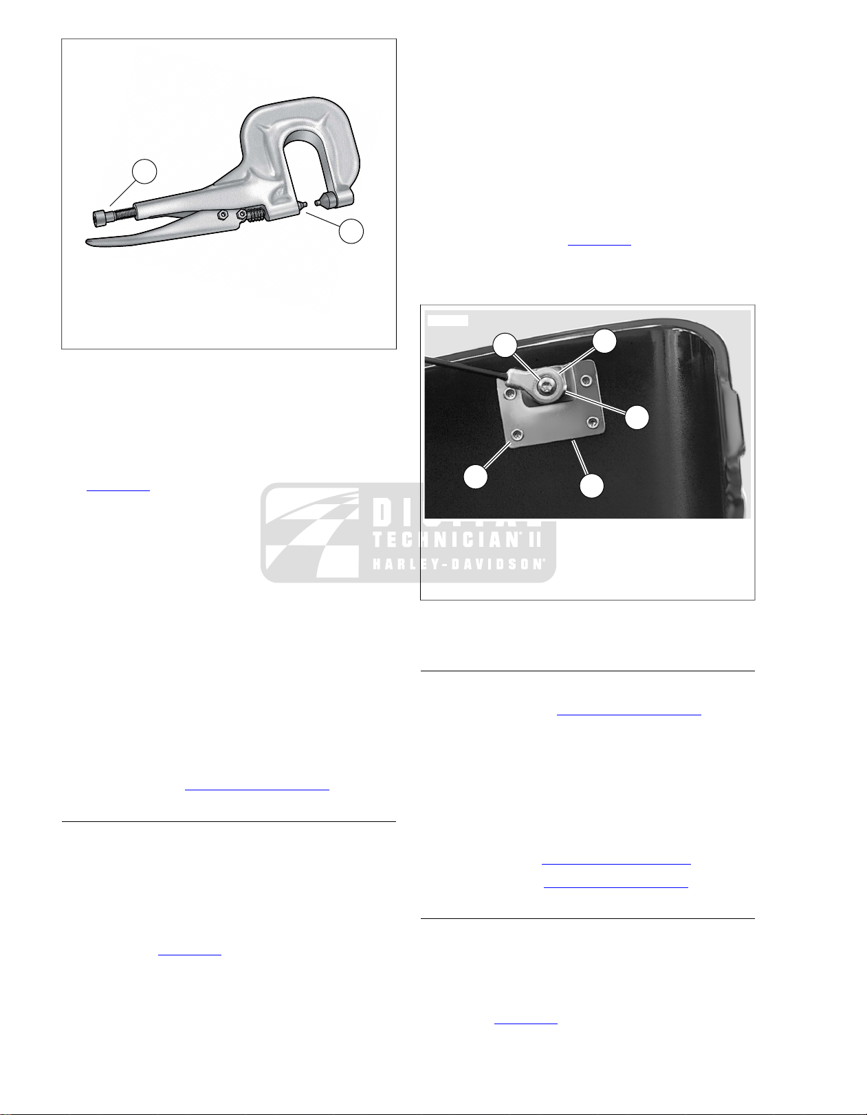
HINGES
TOOL NAMEPART NUMBER
RIVET TOOLHD-39787A
Removal
1. Remove tether. See 2.6 SADDLEBAGS, Tether.
2. Drill off peened end of hinge pin rivet using a 3/8 inch drill
1. Lock guide
2. Jam nut
3. Lockset
4. Cam washer
5. Cam hook
6. Lockwasher
7. Hex nut
Figure 2-9. Lockset Assembly
bit. Use a punch to tap rivet shaft out of hinge.
3. Drill out eight rivets using a 3/16 inch drill bit.
4. Remove hinge and backplates.
2008 FLT Police Service: Chassis 2-11
Page 30
2
1
sm03552
2
1
5
4
3
sm04702
1. Adjuster thumbscrew
2. Drive head
Figure 2-11. Rivet Tool (HD-39787A)
Installation
1. Slide new rivet through holes in hinge, saddlebag and
backplate.
2. Obtain RIVET TOOL (Part No. HD-39787A). See
Figure 2-11.
3. Orient tool so that head of rivet is seated in depression of
drive head.Turn adjuster thumbscrew in or out of handle
until both ends of rivet are captured.
4. Slowly squeeze handle of tool to compress rivet. Turn
adjuster thumbscrew slightly in a clockwise direction and
then squeeze handle again to further compress rivet.
Repeat step as necessary until rivet is fully installed.
NOTE
Compress rivet in small increments only .This method provides
for best retention and alignment of parts and avoids possible
damage to tool and painted surfaces of saddlebag.
5. Repeat previous steps to install remaining rivets.
6. Install lid onto saddlebag engaging upper and lower
hinges.
7. Compress new hinge pin rivet using a suitable rivet tool.
8. Install tether. See 2.6 SADDLEBAGS, Tether.
TETHER
Removal
NOTE
When the tether is removed, use caution to keep lid from
opening beyond its normal travel or damage to painted surf aces
or hinges can occur.
1. Remove T15 TORX screw from threaded boss on tether
bracket. See Figure 2-12.
2. Remove tether eyelet and wave spring from threaded
boss.
3. Repeat previous steps to remove opposite end of tether
from second tether bracket.
Installation
1. With the concave side toward the tether bracket, install
wave spring onto threaded boss.
2. Install tether eyelet onto threaded boss.
3. Apply a small dab of LOCTITE HIGH STRENGTH
THREADLOCKER 262 (red) to threads of T15 TORX
screw.
4. Install screw into threaded boss and tighten to 20-25 in-
lbs (2.3-2.8 Nm). See Figure 2-12.
5. Repeat this procedure to fasten opposite end of tether to
second tether bracket.
1. Tether bracket
2. Rivet (4)
3. T15 TORX screw
4. Tether eyelet
5. Wave spring
Figure 2-12.Tether and Tether Bracket
TETHER BRACKETS
Removal
1. Remove tether. See 2.6 SADDLEBAGS, Tether
2. Drill out four rivets using a 3/16 inch drill bit.
3. Remove tether bracket and backplate.
Installation
1. Slide new rivets through holes in backplate,
saddlebag/saddlebag lid and tether bracket (with the
threaded boss on the outboard side).
2. Install rivets. See 2.6 SADDLEBAGS, Hinges.
3. Install tether. See 2.6 SADDLEBAGS, Tether.
KNOB AND SPRING LATCH
Removal
1. Place multiple strips of masking tape on each side of knob
to protect finished surfaces from scratches and other
damage. Using a large flat blade screwdriver, alternately
pry up each side of knob until free of post. See upper
frame of Figure 2-13.
2-12 2008 FLT Police Service: Chassis
Page 31

2. Remove knob seal and masking tape. Remove any
sm04703
sm04704
1
2
3
sm04705
residual adhesive with 3M general Purpose adhesive
remover (Part No. 051135). See lower frame of
Figure 2-13.
3. Drill out two rivets using a 13/64 inch drill bit. Remove
spring latch. See Figure 2-14.
Installation
1. Hold spring latch at bottom of saddlebag lid with the flat
side facing opposite the hinges. See Figure 2-14.
2. Slide two new rivets through holes in saddlebag lid and
spring latch.
3. Compress rivets using a suitable rivet tool.
4. Peel paper backing off adhesive side of knob seal. Place
knob seal over post, so that the adhesive side contacts
the saddlebag lid. Press knob seal firmly into place.
5. Install knob onto post and alternately work each side down
until it bottoms.
Figure 2-14. Spring Latch
SPRING LATCH BRACKET
Removal
1. From outside saddlebag, loosen two Phillips screws.
2. Inside saddlebag, remove two K eps nuts and spring latch
bracket. Remove Phillips screws. See Figure 2-15.
Installation
1. From outside saddlebag, slide two Phillips scre ws through
holes in saddlebag.
2. Inside saddlebag, install spring latch bracket and two K eps
nuts. See Figure 2-15.
3. Alternately tighten Phillips screws until snug.
1. Spring latch bracket
2. Keps nut (2)
3. Phillips screw (2)
Figure 2-15. Spring Latch Bracket
Figure 2-13. Saddlebag Knob and Seal
2008 FLT Police Service: Chassis 2-13
Page 32

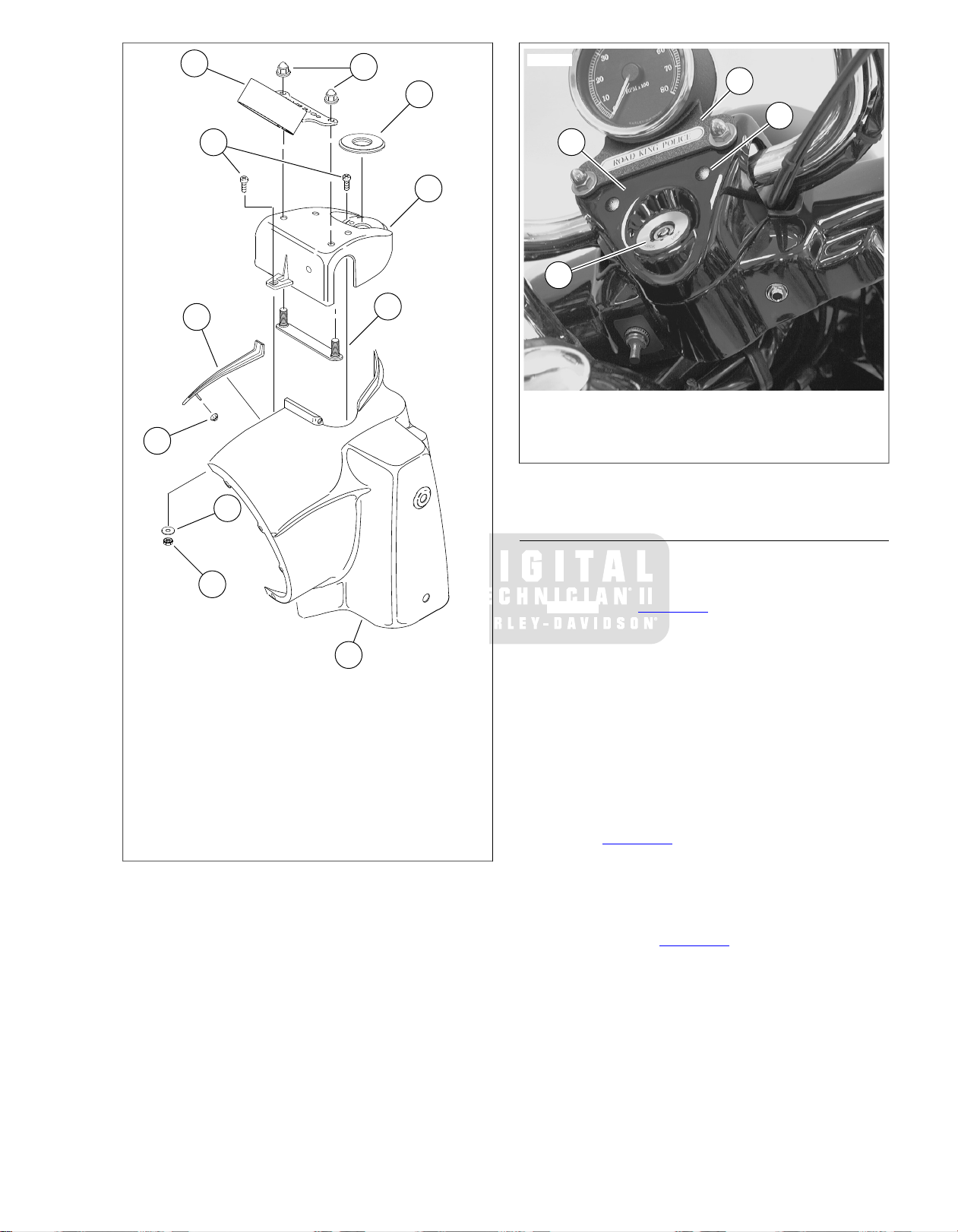
REMOVAL
sm04707
NOTE
The two rear holes in the handlebar clamp shroud allow the
rider to adjust the handlebars without having to remove the
shroud. To keep out moisture and debris, be sure to install
plastic plugs back into holes after handlebar adjustment. See
Figure 2-18.
1. Remove windshield. See WINDSHIELD: FLHR/C in the
Touring Models Service Manual.
2. Remove Phillips screw at bottom of headlamp door
(chrome ring). Remove headlamp door.
3. Remove seven Phillips screws to free headlamp housing
from headlamp nacelle.
4. Remove headlamp connector at back of headlamp bulb.
Remove headlamp housing assembly from motorcycle.
5. From inside the headlamp nacelle:
a. Disconnect tachometer harness connector [20], 6-
place Deutsch. See Figure 2-16.
b. Remove flange nut from weld stud to release chrome
strip at top of nacelle.
c. Catch Keps nut and flat washer while removing Phil-
lips screw from tab at front of handlebar clamp shroud.
2.7TACHOMETER BRACKET: FLHP/E
Figure 2-16. Disconnect Tachometer Connector
6. Carefully pry off the fork lock plate at the rear of the
handlebar clamp shroud. Remove two Phillips screws
beneath the lock plate.
7. Remove the handlebar clamp shroud from the motorcycle,
while gently pulling the tachometer harness conduit and
connector out of the headlamp nacelle.
8. Remove two acorn nuts (with flat washers) to release
tachometer bracket from studs at top of handlebar clamp
shroud.
NOTE
Do not operate ABS equipped motorcycles with the tachometer
removed. While the ABS remains operational, the rider will
receive no warning if a malfunction occurs.The means to report
DTC's also will be eliminated.
2-14 2008 FLT Police Service: Chassis
Page 33
8
9
10
11
1
3
2
4
5
6
7
sm04708
1
4
2
3
sm04709
1. Tachometer bracket
2. Handlebar clamp shroud
3. Fork lock plate
4. Handlebar adjustment access hole plug
Figure 2-18. Install Handlebar Clamp Shroud
INSTALLATION
1. Place tachometer bracket over studs at top of handlebar
clamp shroud. Install two acorn nuts (with flat washers)
onto studs and alternately tighten to 72-108 in-lbs (8.1-
12.2 Nm). See Figure 2-18.
1. Headlamp nacelle
2. Keps nut
3. Flat washer
4. Flange nut
5. Chrome strip
6. Phillips screw (2)
7. Tachometer bracket
8. Acorn nut (2)
9. Fork lock plate
10. Handlebar clamp shroud
11. Stud plate
Figure 2-17. Headlamp Nacelle Assembly
A peel and stick foam tape on the stud plate holds it in place
on the inboard side of the handlebar clamp shroud.
2. Feed tachometer harness connector and conduit through
opening at top of headlamp nacelle. Install handlebar
clamp shroud over mating flange while routing tachometer
harness conduit through opening for left side handlebar.
3. From inside the headlamp nacelle:
a. Start flat washer and Keps nut onto Phillips screw
installed in tab at front of handlebar clamp shroud.
Tighten Phillips screw to 10-20 in-lbs (1.1-2.3 Nm).
See Figure 2-17.
b. Install flange nut onto weld stud of chrome strip
installed into hole at the top of headlamp nacelle.
Tighten flange nut to 15-20 in-lbs (1.7-2.3 Nm).
c. Connect tachometer harness connector [20], 6-place
Deutsch. See Figure 2-16.
NOTE
4. Install two Phillips screws to fasten handlebar clamp
shroud to the fork lock mechanism. Install fork lock plate.
5. Install headlamp connector at back of headlamp bulb.
6. Align holes in headlamp housing with those in headlamp
nacelle (headlamp door bracket at bottom). Install seven
Phillips screws and alternately tighten to 9-18 in-lbs (1.0-
2.0 Nm).
2008 FLT Police Service: Chassis 2-15
Page 34

7. Fit the square-shaped portion of the headlamp door spring
into slot at top of headlamp housing and then snap the
headlamp door (chrome ring) into place. Install Phillips
screw at bottom of headlamp door and tighten to 9-18 in-
lbs (1.0-2.0 Nm).
8. Install windshield. See WINDSHIELD: FLHR/C in the
Touring Models Service Manual.
2-16 2008 FLT Police Service: Chassis
Page 35

SUBJECT............................................................................................................................PAGE NO.
3.1 SPECIFICATIONS: ENGINE.....................................................................................................3-1
3.2 SERVICE WEAR LIMITS...........................................................................................................3-2
3.3 OIL COOLER.............................................................................................................................3-3
ENGINE
Page 36

NOTES
Page 37
3.1SPECIFICATIONS: ENGINE
GENERAL
Table 3-1. Engine: 2008 Police Models
Type
Torque
Pump
Pressure
Filtration
SPECIFICATIONITEM
2Number of cylinders
4-cycle, 45 degree
V-Type, air cooled
9.6-1Compression ratio
98 mm3.875 in.Bore
111 mm4.375 in.Stroke
1690 cc103 cu. in.Displacement
102 ft-lbs @
2500 RPM
Table 3-2. Oiling System
SPECIFICATIONITEM
Twin gerotor, dual scavenge, crank
mounted and driven, internal oil pump,
dry sump
30-38 psi (207-262 kN/m2) at 2000 RPM
and normal operating temperature of
230° F (110° C)
10 micron media, filtered between pump
and engine
Thermostat controlled oil coolerCooling
138 Nm @
2500 RPM
MANUFACTURING TOLERANCES
Table 3-3.Valves
MMIN.ITEM
0.038-0.0840.0015-0.0033Fit in guide (exhaust)
0.020-0.0660.0008-0.0026Fit in guide (intake)
50.55-51.411.990-2.024Stem protrusion from
cylinder head boss
Table 3-4.Valve Spring Assembly
DIMENSIONPRESSUREITEM
1.820 in. (46.2 mm)165 lbs (75 kg)Closed
1.290 in. (32.7 mm)416 lbs (189 kg)Open
2.210 in. (56.1 mm)n/aFree length
Table 3-5. Connecting Rods
MMINCHESITEM
0.008-0.0180.0003-0.0007Piston pin fit (loose)
Table 3-6. Crankshaft/Sprocket Shaft Bearing
MMINCHESITEM
0.0025-0.02540.0001-0.0010Bearing inner race on
crankshaft (tight)
2008 FLT Police Service: Engine 3-1
Page 38
3.2SERVICE WEAR LIMITS
GENERAL
Wear limits can be used as a guide when deciding whether to
reuse engine parts. Replace used parts whenever the f ollowing
wear limits are exceeded.
Table 3-7. Cam Support Plate
REPLACE IF WEAR EXCEEDSITEM
MMINCHES
2.03-2.290.080-0.090Cam chain tensioner
shoe
0.250.010Warpage
0.0203-0.02540.0008-0.001Crankshaft bushing fit
Table 3-8. Cylinder Bore
REPLACE IF WEAR EXCEEDSITEM
Table 3-9. Connecting Rods
REPLACE IF WEAR EXCEEDSITEM
Table 3-10. Crankshaft/Sprocket Shaft Bearing
REPLACE IF WEAR EXCEEDSITEM
Crankshaft runout
(tight)
crankshaft (tight)
Greater than
0.003
MMINCHES
98.483.877Standard
98.603.8820.005 in. oversize
98.733.8870.010 in. oversize
MMINCHES
0.0250.001Piston pin fit (loose)
MMINCHES
Greater than
0.076
0.097-0.1370.0038-0.0054Bearing fit in crankcase
Less than 0.0254Less than 0.0001Bearing inner race on
Table 3-11.Valve Stem to Guide Clearance
REPLACE IF WEAR EXCEEDSITEM
MMINCHES
0.0890.0035Intake
0.1020.0040Exhaust
3-2 2008 FLT Police Service: Engine
Page 39

OPERATION
1
2
3
sm04710
8
10
9
5
6
7
1
2
3
4
sm04712
Pressurized oil flows through a hole in the oil filter mount into
a passage in the oil cooler adapter.The oil cooler adapter is
mounted between the oil filter mount and the oil filter.
A thermostat inside the oil cooler adapter controls the flow of
oil to the oil cooler.The ther mostat consists of a temperature
sensitive element compressed between a spring and threaded
plug. See Figure 3-1.
While the engine oil temperature is below 200° F (93° C), the
thermostat is open allowing most of the engine oil to pass from
the supply port directly to the return por t en route to the oil
filter.
When the engine oil temperature reaches 200° F (93° C), the
thermostat closes and the entire flow is directed to the oil cooler
through the supply hose.
The fins on the tubes of the oil cooler dissipate heat before the
flow returns to the oil cooler adapter through the return hose.
The engine oil then passes through the oil filter before returning
to the crankcase.
NOTE
For a complete description of the engine oil flow, see GENERAL INFORMATION in the Touring Models Service Manual.
3.3OIL COOLER
1. Return fitting
2. Supply fitting
3. Thermostat
Figure 3-1. Oil Cooler Adapter
1. Flange nut (3)
2. Flat washer (3)
3. Mounting bracket
4. Oil cooler
5. Supply hose
6. Return hose
7. Hose clamp (4)
8. Oil cooler adapter
9. Oil filter adapter
10. Adhesive gasket
Figure 3-2. Oil Cooler Assembly
REMOVAL
1. Place a suitable drain pan beneath the oil cooler.
2. See Figure 3-2. Remove three flange nuts with flat
washers. Raise oil cooler to free threaded studs from holes
in mounting bracket.
3. Using a side cutters, cut and remove clamps on oil cooler
adapter side of supply and return hoses. Pull hoses from
fittings.
4. Remove oil cooler from motorcycle.
5. Using a side cutters, cut and remove clamps on oil cooler
side of supply and return hoses. Pull hoses from fittings.
2008 FLT Police Service: Engine 3-3
Page 40
6. Remove mounting bracket as follows:
a. Remove voltage regulator and front electrical caddy.
See VOLTAGE REGULATOR in the Touring Models
Service Manual.
b. Lift mounting bracket off studs on low er frame cross-
member.
CLEANING AND INSPECTION
1. Using a clean shop cloth or soft bristle brush, gently clean
oil cooler fins of dirt and debris.
2. If engine failure and/or oil contamination requires inspection and cleaning of oil passageways, then remove oil
cooler adapter and proceed as follows:
a. See Figure 3-3. Remove two socket screws (3) to
release inspection cover (4) and gasket (2).
b. Thoroughly flush oil passageways with solvent and
blow out with compressed air.
c. Install inspection cover with new gasket.
d. Apply a small dab of Loctite Medium Strength
Threadlocker 243 (blue) to threads of soc k et scre ws .
Install screws and alternately tighten to 90-120 in-
lbs (10.2-13.6 Nm).
INSTALLATION
TOOL NAMEPART NUMBER
HOSE CLAMP PLIERSHD-97087-65B
NOTE
If mounting bracket is already installed, proceed to next step.
1. Install mounting bracket as follows:
a. With the "TOP" stamp facing upw ard, install mounting
bracket onto studs on lower frame crossmember.
b. Install front electrical caddy and voltage regulator.
See VOLTAGE REGULATOR in the Touring Models
Service Manual.
2. Slide new clamp onto oil cooler side of return hose, which
can be identified by the paint stamp reading COOLER
BOTT OM.With the script facing upward, install hose onto
bottom fitting of oil cooler. Crimp clamp using HOSE
CLAMP PLIERS (Part No. HD-97087-65B).
3. Slide new clamp onto oil cooler side of supply hose, which
can be identified by the paint stamp reading COOLER
TOP.With the script facing upward, install hose onto top
fitting of oil cooler. Crimp clamp.
NOTE
If the paint stamps are not present, the long hose is the return
and the short hose is the supply. Install both hoses, so that the
90° bend goes to the oil cooler adapter.
4. Slide threaded studs at bottom of oil cooler through holes
in mounting bracket. Install flat washers and flange nuts
on studs. Alternately tighten flange nuts to 70-100 in-
lbs (7.9-11.3 Nm).
5. Slide new clamp onto free end of return hose (stamped
COOLER BOTTOM). Install hose on upper fitting of oil
cooler adapter. Crimp clamp using HOSE CLAMP
PLIERS (Part No. HD-97087-65B).
6. Slide new clamp onto free end of supply hose (stamped
COOLER TOP). Install hose on lower fitting of oil cooler
adapter. Crimp clamp.
7. Check engine oil level. See ENGINE OIL AND FILTER in
the Touring Models Service Manual.
OIL COOLER ADAPTER AND THERMOST A T REPLACEMENT
TOOL NAMEPART NUMBER
HOSE CLAMP PLIERSHD-97087-65B
Removal
NOTE
A faulty thermostat requires replacement of the oil cooler
adapter.
1. Place a suitable drain pan beneath the oil cooler and oil
filter.
2. Using a side cutters, cut and remove clamps on oil cooler
adapter side of supply and return hoses. Pull hoses from
fittings.
3. Remove the engine oil filter. See ENGINE OIL AND
FILTER in the Touring Models Service Manual.
4. Using internal hex, remove the oil filter adapter. Remove
the oil cooler adapter and gasket. See Figure 3-2.
Installation
NOTE
Skip first step if hose fittings are already installed.
1. Install hose fittings as follows:
a. Install hose fittings until finger tight.
b. Using wrench on flats, rotate hose fittings an addi-
tional 2-3 turns.
2. Position oil cooler adapter flange against oil filter mount.
Index tabs on flange engage a recess on each side of the
oil filter mount oil outlet hole. See Figure 3-3.
3. Apply Loctite High Temperature/Medium Strength
Threadlocker 246 to threads of oil filter adapter.With the
internal hex on the outboard side, thread oil filter adapter
into oil filter mount. Holding the oil cooler adapter to prevent rotation, tighten oil filter adapter to 18-22 ft-lbs (24.4-
29.8 Nm).
4. Slide new clamp onto free end of return hose (stamped
COOLER BOTTOM). Install hose on upper fitting of oil
cooler adapter. Crimp clamp using HOSE CLAMP
PLIERS (Part No. HD-97087-65B).
5. Slide new clamp onto free end of supply hose (stamped
COOLER TOP). Install hose on lower fitting of oil cooler
adapter. Crimp clamp.
6. Install new oil filter and check engine oil level. See
ENGINE OIL AND FILTER in the Touring Models Service
Manual.
7. Start engine and inspect oil cooler/adapter fittings and
hoses for leaks.
3-4 2008 FLT Police Service: Engine
Page 41

1
2
3
4
sm04713
1. Index tabs
2. Adhesive gasket
3. Socket screw (2)
4. Inspection cover
Figure 3-3. Oil Cooler Adapter
2008 FLT Police Service: Engine 3-5
Page 42

NOTES
3-6 2008 FLT Police Service: Engine
Page 43

SUBJECT............................................................................................................................PAGE NO.
4.1 FUEL SYSTEM..........................................................................................................................4-1
FUEL SYSTEM
Page 44

NOTES
Page 45

NO UNIQUE CONTENT
Any information not presented in this supplement can be found
in the Touring Models Service Manual.
4.1FUEL SYSTEM
2008 FLT Police Service: Fuel System 4-1
Page 46

NOTES
4-2 2008 FLT Police Service: Fuel System
Page 47

SUBJECT............................................................................................................................PAGE NO.
5.1 ELECTRIC STARTER................................................................................................................5-1
ELECTRIC STARTER
Page 48

NOTES
Page 49

NO UNIQUE CONTENT
Any information not presented in this supplement can be found
in the Touring Models Service Manual.
5.1ELECTRIC STARTER
2008 FLT Police Service: Electric Starter 5-1
Page 50

NOTES
5-2 2008 FLT Police Service: Electric Starter
Page 51

SUBJECT............................................................................................................................PAGE NO.
6.1 DRIVE........................................................................................................................................6-1
DRIVE
Page 52

NOTES
Page 53

NO UNIQUE CONTENT
Any information not presented in this supplement can be found
in the Touring Models Service Manual.
6.1DRIVE
2008 FLT Police Service: Drive 6-1
Page 54

NOTES
6-2 2008 FLT Police Service: Drive
Page 55

SUBJECT............................................................................................................................PAGE NO.
7.1 TRANSMISSION.......................................................................................................................7-1
TRANSMISSION
Page 56

NOTES
Page 57

NO UNIQUE CONTENT
Any information not presented in this supplement can be found
in the Touring Models Service Manual.
7.1TRANSMISSION
2008 FLT Police Service: Transmission 7-1
Page 58

NOTES
7-2 2008 FLT Police Service: Transmission
Page 59

SUBJECT............................................................................................................................PAGE NO.
8.1 BULB CHART............................................................................................................................8-1
8.2 SYSTEM FUSES AND RELAYS...............................................................................................8-3
8.3 REAR MARKER LIGHTS..........................................................................................................8-5
8.4 HANDLEBAR SWITCHES.........................................................................................................8-6
8.5 AUTOMATIC COMPRESSION RELEASE...............................................................................8-10
ELECTRICAL
Page 60

NOTES
Page 61
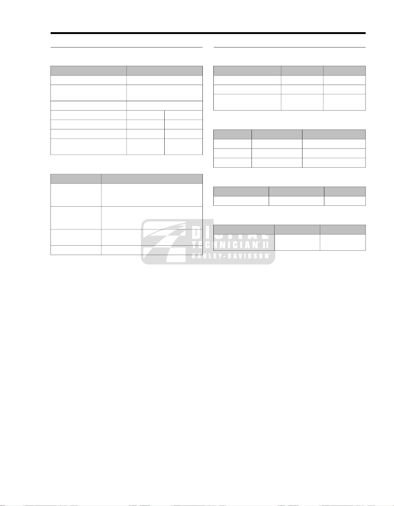
GENERAL
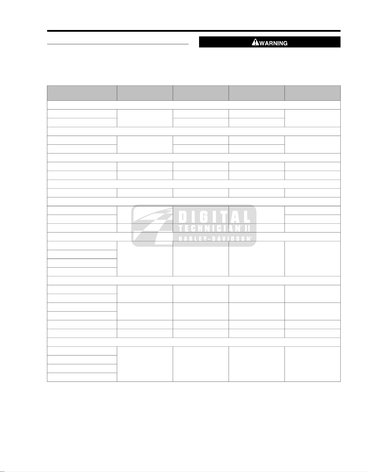
8.1BULB CHART
The table below gives the bulb requirements for FLHTP and
FLHP/E police model motorcycles.
Table 8-1. Bulb Chart FLHTP, FLHP/E
LAMP DESCRIPTION
(ALL LAMPS 12V)
Head Lamp
Tail/Stop Lamp
Turn Signal Lamp
Rear Fender Tip Lamp
Pursuit Lamp
Instrument Panel Lamps-FLHTP Indicator Module (with LEDs)
Oil Pressure Indicator**
Neutral Indicator**
Turn Signal Indicator**
Gauge Lamps-FLHTP
Tachometer**
Fuel Gauge
Instrument/Gauge Lamps-FLHP/E Indicator Module (with LEDs)
Oil Pressure Indicator**
Neutral Indicator**
Turn Signal Indicator**
NUMBER OF BULBS
(REQUIRED)
(AMPERAGE)
The rear strobe is a source of high voltage and must be
off at least 10 minutes before servicing. Inadequate safety
precautions may result in death or serious injury . (00097a)
WATTAGECURRENT DRAW
605.00HIgh Beam
242.10Stop Lamp
HARLEY-DAVIDSON
PART NUMBER
68329-03554.581Low Beam
68167-8860.591Tail Lamp
68168-8927/72.25 / 0.592Front / Running
68572-64B272.252Rear
53439-793.70.332Rear Fender Tip Bulb
68727-64A302.51Left (Red)
68728-64Right (Blue)
67598-8820N/ARear Strobe, if provided
68859-07N/A0.05N/AHigh Beam Indicator**
N/AN/AN/AN/ASpeedometer**
67445-003.40.241Voltmeter
N/AN/AN/AN/AEngine**
68642-961.10.081Pursuit (fairing)
68113-99BN/A0.05N/AHigh Beam Indicator**
2008 FLT Police Service: Electrical 8-1
Page 62

Table 8-1. Bulb Chart FLHTP, FLHP/E
LAMP DESCRIPTION
(ALL LAMPS 12V)
Speedometer**
Odometer**
Engine**
Pursuit**
** LED illuminated. LEDs are not repairable. Assembly must be replaced if LED fails.
NUMBER OF BULBS
(REQUIRED)
(AMPERAGE)
WATTAGECURRENT DRAW
HARLEY-DAVIDSON
PART NUMBER
N/AN/AN/AN/AFuel Gauge**
8-2 2008 FLT Police Service: Electrical
Page 63

SYSTEM FUSES
ed01646
21
20
18
109
8
5
6
7
4
3
21
17
16
15
11 12 13 14
19
ed01653
8.2SYSTEM FUSES AND RELAYS
Removal
1. Verify that the Ignition/Light Key Switch is turned to the
OFF position.
2. Remove left side saddlebag.
3. See Figure 8-1. Remove wing nut style bolt to release
bottom of siren amplifier mounting bracket from clamp on
saddlebag guard. Rotate brac ket upward to gain complete
access to side cover area. Loosen top bolt, if necessary.
4. Gently pull side cover from frame downtubes (no tools
required). Ex ercise caution to a void scratching side cover
on amplifier mounting bracket.
5. Raise the fuse block cover.
NOTE
The fuse block cov er has a fuse puller attachment that may be
used to remove fuses.
6. Remove fuse from fuse block and inspect the element.
7. See Figure 8-2 to identify fuse location. Replace fuse if
element is burned or broken. Automotive type ATO fuses
are used.
Always use replacement fuses that are of the correct type
and amperage rating. Use of incorrect fuses can result in
damage to electrical systems. (00222a)
Figure 8-1. Siren Amplifier Mounting Bracket
2. 16.9.Accessory (15A) Headlamp (15A)EFI system relay
Radio/Siren (15A)
5. 19.Radio memory (if equipped)
(15A)
6. 21.13.Battery (15A) MAXIFUSE (40A)Ignition (15A)
Figure 8-2. Left Side Electrical Caddy
10.3. 17.Starter relayP&A (15A) Lighting (15A)
max)
12. 20.Instruments (15A) Spare (30A)
14.7. Engine control (15A)ECM power (15A)
15.8.1. Brake light relayFuel pump (15A)Brakes/Pursuit (15A)
18.11.4. Spare (15A)P&A ignition (if equipped) (2A
ABS (if equipped) (30A)
2008 FLT Police Service: Electrical 8-3
Page 64

Installation
1. Install fuse in fuse block. For correct type and amperage
rating, refer to Figure 8-2.
2. Install cover on fuse block.
3. Align barbed studs in side cover with grommets in frame
downtubes and push firmly into place (no tools required).
4. Rotate siren amplifier mounting bracket downw ard. Install
wing nut style bolt to secure bracket to clamp on saddlebag
guard.Tighten top bolt, if loosened.
5. Install left side saddlebag.
8-4 2008 FLT Police Service: Electrical
Page 65

8.3REAR MARKER LIGHTS
1
2
3
4
5
ed01647
MARKER LIGHTS REPLACEMENT
1. On inboard side of rear marker lights bracket, gently pull
electrical connector from prongs on marker light.
2. Rotate marker light in a counterclockwise direction and
remove from hole in rear marker lights bracket.
3. Place new marker light into hole in rear marker lights
bracket and rotate in a clockwise direction to install.
4. On inboard side of rear marker lights bracket, gently push
electrical connector onto prongs on marker light.
REMOVAL
1. Disconnect rear marker lights harness connector [12], 3place Multilock, inboard of left upper frame tube.
2. Carefully cut cable strap to release rear marker lights (and
pole lamp) conduit from left side of bottom support tube.
3. On inboard side of license plate bracket, note that catches
on rear marker lights bracket engage oblong holes in
license plate bracket. Using tip of flat blade screwdriver,
gently push top catch down and then bottom catch up to
release from oblong hole. Repeat step to release other
side of rear marker lights bracket.
4. Remove rear marker lights assembly from motorcycle.
INSTALLATION
1. Gently pull both electrical connectors from prongs to
detach rear marker lights harness.
2. On inboard side of left upper frame tube, mate pin and
socket housings of rear marker lights harness connector
[12], 3-place Multilock.
3. Route free end of rear marker lights conduit rearward following inboard side of bottom support tube.When conduit
reaches air reservoir, loop left side rear marker light conduit to outboard side, while routing right side rear marker
light conduit between top of bottom support tube and
bottom of air reservoir bracket to right side of motorcycle.
4. Engage catches on each side of rear marker lights bracket
into oblong holes in license plate bracket.
5. On inboard side of rear marker lights bracket, gently push
electrical connectors onto prongs on marker lights.
6. Install new cable strap to secure rear marker lights (and
pole lamp) conduit to left side of bottom support tube. Cut
any excess cable strap material.
1. Rear marker light (2)
2. Rear marker lights bracket
3. Rear marker lights harness
4. License plate bracket
5. Bottom support tube
Figure 8-3. Rear Marker Lights Assembly
2008 FLT Police Service: Electrical 8-5
Page 66

HORN AND SIREN YELP SWITCH
2
3
4
5
1
ed01654
2
3
4
5
1
ed01655
NOTE
Install new cable strap to secure rear marker lights (and pole
lamp) conduit to left side of bottom support tube. Cut any
excess cable strap material.
Removal
1. Gain access to the inside of the switch housing. See
HANDLEBAR SWITCH ASSEMBLIES in the Touring
Models Service Manual.
2. From inside the switch housing, carefully cut cable strap
to free conduit from the turn signal switch bracket.
3. Remove the Phillips screw (with lockwasher) to release
the turn signal switch bracket. Remove the switch
assembly from the housing.
4. Remove the two T8 TORX screws and the Phillips screw
(with lockwasher) to release the lower bracket. Carefully
lift out the bracket so as not to disturb the spring-loaded
ramp on the inboard side of the housing.
5. Carefully remove the keycap disengaging slot from hook
on ramp.
6. While holding down the ramp, pull both s witches from the
housing.
7. Cut the wires from the old switches as follows:
a. Yellow/Black wire: 1-1/4 in. (32 mm)
b. Orange/White wires: 1-7/8 in. (48 mm)
c. Brown/Black wire: 1-1/2 in. (38 mm)
8.4HANDLEBAR SWITCHES
1. Engine start switch
2. Front stoplight switch
3. Engine stop switch: Off/Run
4. Pole and pursuit lamp switc h: Off/A uxiliary/Pursuit
5. Turn-right signal switch
Figure 8-4. Right Handlebar Switch Housing
NOTE
Replacement Horn/Siren Yelp Switch wires are cut to length
and partially stripped (Yellow/Black wire: 3-3/4 in. (95 mm);
Orange/White wires: 3-1/2 in. (89 mm); Brown/Black wire: 33/8 in. (86 mm).
8. Connect wires of new switch. See HANDLEBAR SWITCH
ASSEMBLIES in the Touring Models Service Manual.
NOTE
If the ramp and spring mechanism becomes loose, install as
follows:
• Using the blade of a small screwdriver, compress spring
and place in wider portion of channel at bottom of ramp.
• V erify that spring is evenly compressed and is not coc k ed
or skewed. Push spring so that it bottoms in channel.
• With tab side of ramp facing inboard and hook end on
switch side of casting, install ramp so that narrow channels
engage pins cast into housing.
8-6 2008 FLT Police Service: Electrical
1. Clutch/starter interlock switch
2. Siren switch: On/Off
3. Light switch: high and low beams
4. Turn-left signal switch
5. Horn/siren yelp switch
Figure 8-5. Left Handlebar Switch Housing
Installation
1. Install the switches in the housing with contacts facing
tabs on ramp. F or best results, install one s witch at a time.
Ribs cast in lower housing hold switches in position.
The Horn switch with the Yellow/Black lead (pivot point
towards rider) is installed at the bottom, while the Siren
Yelp switch with the Brown/Black lead (pivot point tow ards
the front) is at the top. Route switch wires in channel on
the outboard side of the ribbed area.
Page 67

2. Install the keycap engaging slot with hook on ramp.
3. Install lower bracket sliding pin through keycap and
engaging hole in lower casting.
4. Slide T8 T ORX screws through holes in lo wer brack et and
switches and thread into lower casting until snug.
5. Install Phillips screw (with lockwasher), to secure lower
bracket to threaded boss in housing.Verify operation of
Horn and Siren Yelp switches to ensure that both are
spring returned.
6. Install clutch interlock switch in bore of lower switch
housing, if loose.
7. Insert tapered end of new 7-inch cable strap into round
hole in turn signal switch bracket and then feed back
through using the adjacent hole. Reserve the oblong hole
for the bracket screw.
NOTE
Be sure that all splices are positioned above the turn signal
switch bracket.
8. Place the turn signal switch assembly into the housing
aligning the oblong hole in the bracket with the lower
bracket weld nut. Be sure that bracket is fully seated.T abs
on each side are captured in slots cast into switch housing.
9. Install Phillips screw (with lockwasher) to secure bracket
inside housing.
If routed incorrectly, wires can be pinched by casting or
handlebar resulting in switch failure. (00542b)
10. Loop switch wires so that spliced lengths are positioned
directly over bracket screw.
11. Capturing conduit about 1/4 inch (6 mm) from end,
securely tighten cable strap to draw conduit to bracket.
Remove any excess cable strap material.
12. On opposite side, install second 7-inch cable strap cap-
turing conduit and wire splices. Securely tighten cable
strap to draw splices to conduit. Remov e any excess cab le
strap material.
13. Route wire bundle to upper switch housing below and then
forward of the main wire harness positioning conduit in
channel next to angular arm of bracket. Secure bundle to
arm placing new cable strap 1/4 inch (6 mm) from end of
conduit. Cut an y excess cable str ap material. If necessary,
bend angular arm of bracket downward to firmly secure
clutch interlock switch in installed position.
14. See HANDLEBAR SWITCHES in the Touring Models
Service Manual.
CLUTCH INTERLOCK SWITCH
NOTE
All Police models have a clutch interlock switch that prevents
the motorcycle from starting (even in NEUTRAL) if the clutch
lever is not pulled in.
Removal
1. See HANDLEBAR SWITCH ASSEMBLIES in the Touring
Models Service Manual.
2. From inside the switch housing, carefully cut cable strap
to free conduit from the turn signal switch bracket.
3. Remove the Phillips screw (with lockwasher) to release
the turn signal switch bracket. Remove the switch
assembly from the housing.
4. Remove the clutch interlock switch from the housing.
5. Cut wires 1/4 in. (6 mm) from old switch. Discard switch
assembly.
NOTE
Replacement clutch interlock switch wires are cut to length.
Looking at rear side, left side switch wire is 2-1/4 in. (57 mm),
and right side is 2-3/4 in. (70 mm) and partially stripped.
6. Connect wires of new switch. See HANDLEBAR SWITCH
ASSEMBLIES in the Touring Models Service Manual.
Installation
1. Install clutch interlock switch in bore of lower switch
housing.
2. Insert tapered end of new 7-inch cable strap into round
hole in turn signal switch bracket and then feed back
through using the adjacent hole. Reserve the oblong hole
for the bracket screw.
NOTE
Be sure that all splices are positioned above the turn signal
switch bracket.
3. Place the turn signal switch assembly into the housing
aligning the oblong hole in the bracket with the lower
bracket weld nut. Be sure that bracket is fully seated.T abs
on each side are captured in slots cast into switch housing.
4. Install Phillips screw (with lockwasher) to secure bracket
inside housing. If routed incorrectly, wires may be pinched
by casting or handlebar resulting in switch failure.
If routed incorrectly, wires can be pinched by casting or
handlebar resulting in switch failure. (00542b)
5. Loop switch wires so that spliced lengths are positioned
directly over bracket screw.
6. Capturing conduit about 1/4 in. (6 mm) from end, securely
tighten cable strap to draw conduit to bracket. Remove
any excess cable strap material.
7. On opposite side, install second 7-inch cable strap cap-
turing conduit and wire splices. Securely tighten cable
strap to draw splices to conduit. Remov e any excess cab le
strap material.
8. Route wire bundle to upper switch housing below and then
forward of the main wire harness positioning conduit in
channel next to angular arm of bracket. Secure bundle to
arm placing new cable strap 1/4 in. (6 mm) from end of
conduit. Cut an y excess cable str ap material. If necessary,
bend angular arm of bracket downward to firmly secure
clutch interlock switch in installed position.
9. See HANDLEBAR SWITCH ASSEMBLIES in the Touring
Models Service Manual.
2008 FLT Police Service: Electrical 8-7
Page 68

ed01649
Figure 8-6. Lower Switch Housing
PURSUIT AND AUXILIARY SWITCH
NOTE
Pursuit lamps are operational on domestic motorcycles only.
Removal
1. See HANDLEBAR SWITCH ASSEMBLIES in the Touring
Models Service Manual.
2. From inside the switch housing, carefully cut cable strap
to free conduit from the turn signal switch bracket.
3. Remove the Phillips screw (with lockwasher) to release
the turn signal switch bracket. Remove the switch
assembly from the housing.
4. Remove the two T8 TORX screws and the Phillips screw
(with lockwasher) to release the lower bracket. Remove
the bracket from the housing.
5. Pull both switches from the housing.
6. Cut the wires from the old switches as follows:
a. Gray/Black wire: 1-1/2 in. (38 mm)
b. Orange/Violet wires: 1-7/8 in. (48 mm)
c. Green/Red wire: 1-1/4 in. (32 mm)
NOTE
Replacement pursuit/auxiliary switch wires are cut to length
and partially stripped (Gray/Black wire: 2 in. (51 mm);
Orange/Violet wires: 1-7/8 in. (48 mm); Green/Red wire: 13/4 in. (45 mm).
7. Connect wires of new switch. See HANDLEBAR SWITCH
ASSEMBLIES in the Touring Models Service Manual.
8. Move keycap to the OFF position. Install the switches in
the housing with contacts facing the recessed area on the
ramp. Ribs cast in lower housing hold s witches in position.
The Auxiliary switch with the Gray/Black lead is installed
at the bottom, while the Pursuit switch with the Green/Red
lead is at the top. Route switch wires into corner space
outside of the ribbed area.
NOTE
If the keycap and ramp mechanism requires replacement,
install as follows:
• Slide ramp upward to remove from keycap shaft.
• Remove keycap from switch housing.
• Install spring into hole on inboard side of new keycap.
Position ball on end of spring. Use a small amount of
grease to hold ball in place.
• Install keycap so that ball engages detent in switch
housing.
• Slide ramp over keycap shaft so that tongues on ramp
engage grooves in keycap shaft.
Installation
1. Install lower bracket with the weld nut side down.
2. Slide the T8 TORX scre ws through holes in lo wer br ac k et
and switches and thread into lower casting until snug.
3. Install Phillips screw (with lockwasher), to secure lower
bracket to threaded boss in housing.Work Auxiliary and
Pursuit switches to ensure smooth operation.
4. See Figure 8-7. Insert tapered end of new 7-inch cable
strap into round hole in turn signal switch bracket and then
feed back through using the adjacent hole. Reser ve the
oblong hole for the bracket screw.
NOTE
Be sure that all splices are positioned above the turn signal
switch bracket.
5. Place the turn signal switch assembly into the housing
aligning the oblong hole in the bracket with the lower
bracket weld nut. Be sure that bracket is fully seated.T abs
on each side are captured in slots cast into switch housing.
6. Install Phillips screw (with lockwasher) to secure turn signal
switch bracket inside housing.
If routed incorrectly, wires can be pinched by casting or
handlebar resulting in switch failure. (00542b)
7. Loop switch wires so that spliced lengths are positioned
directly over bracket screw.
8. Capturing conduit about 1/4 in. (6 mm) from end, securely
tighten cable strap to draw conduit to bracket. Remove
any excess cable strap material.
9. On opposite side, install second 7-inch cable strap cap-
turing conduit and wire splices. Securely tighten cable
strap to draw splices to conduit. Remov e any excess cab le
strap material.
10. Route wire bundle to upper switch housing in channel next
to angular arm of bracket. Secure bundle to arm placing
new cable strap 1/4 in. (6 mm) from end of conduit. Cut
any excess cable strap material. If necessary, bend
8-8 2008 FLT Police Service: Electrical
Page 69
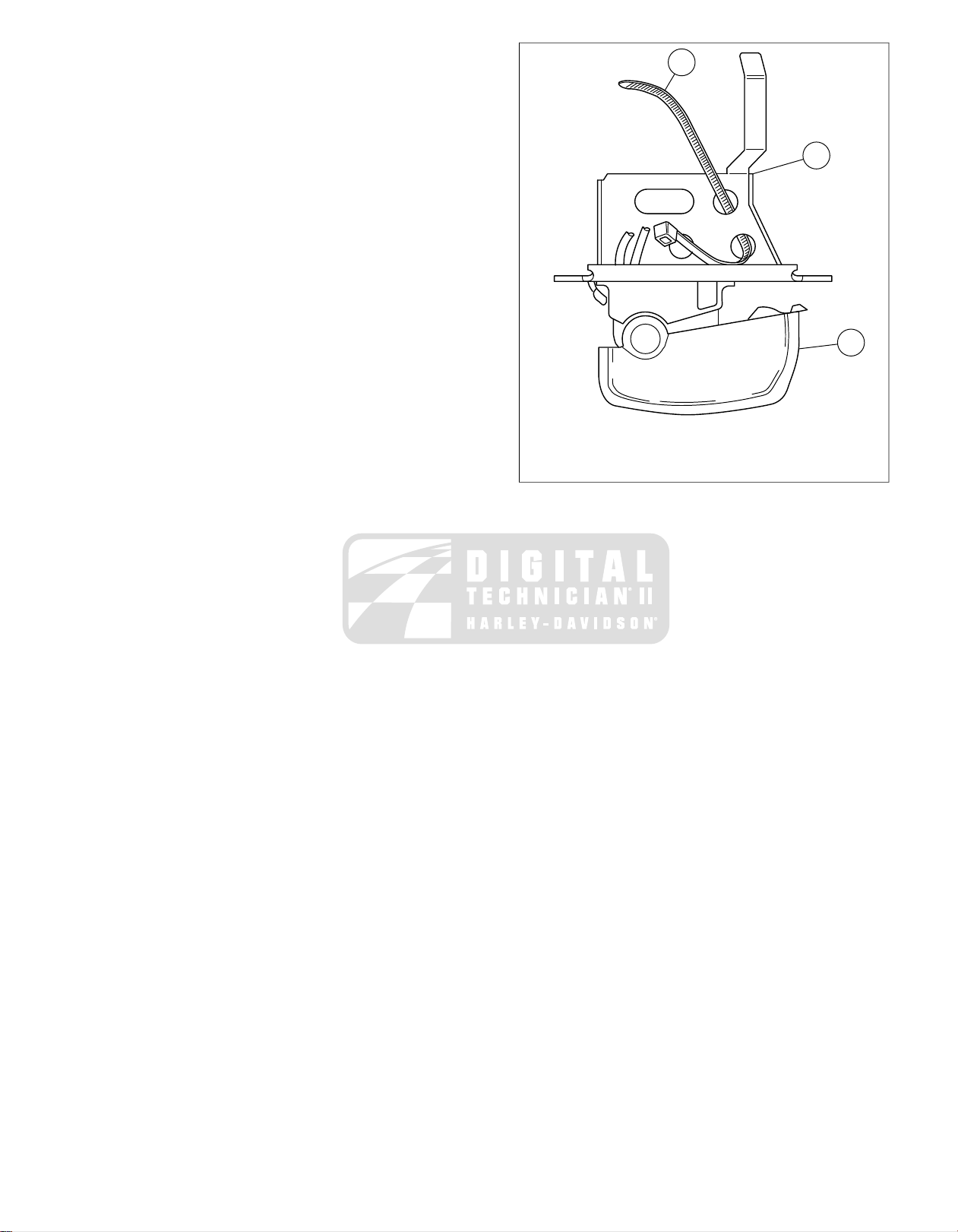
angular arm of bracket downward to firmly secure Front
1
2
3
ed01650
Stoplight Switch in installed position.
11. See HANDLEBAR SWITCH ASSEMBLIES in the T ouring
Models Service Manual.
1. 7" cable strap
2. Bracket
3. Right turn signal switch
Figure 8-7. Hole Location Cable Strap Switch Bracket
2008 FLT Police Service: Electrical 8-9
Page 70

GENERAL
ed01623
ed01624
ed01625
See Figure 8-8. The Automatic Compression Release (ACR)
is opened and closed by the ECM to assist starting.
See Figure 8-9.When open, compressed gases are released
through the exhaust port.
REMOVAL
TOOL NAMEPART NUMBER
ACR SOLENOID SOCKETHD-48498
1. While preparing motorcycle for service, separate the ACR
rear [203R] and front [203F] connectors from the main
wiring harness.
2. Remove the rocker cover and the rocker box. See
STRIPPING MOTORCYCLE FOR SERVICE and TOP
END OVERHAUL in the Service Manual for procedures.
3. See Figure 8-13. Use ACR SOLENOID SOCKET (Part
No. HD-48498) to remov e the ACR from the cylinder head.
8.5AUTOMATIC COMPRESSION RELEASE
Figure 8-10. ACR in Head
INSTALLATION
TOOL NAMEPART NUMBER
ACR SOLENOID SOCKETHD-48498
Figure 8-8. ACR Valve in Combustion Chamber
1. V erify that the copper seal washer is in place on the ACR.
2. See Figure 8-11. Identify a location around the threads of
the ACR approximately 1/3 of the way up from the end.
3. See Figure 8-12. Apply three equally spaced dots of
LOCTITE 246 THREADLOCKER MEDIUM
STRENGTH/HIGH TEMPERATURE (blue) on threads.
4. To prevent cross threading, install and finger tighten.
5. See Figure 8-13. Using ACR SOLENOID SOCKET (Part
No. HD-48498), tighten to 11-15 ft-lbs (14.9-20.3 Nm).
6. Before installing the rocker box on each cylinder head,
route the wire harness toward the inside of the cylinder V.
7. With rocker box es installed and the engine in the chassis ,
mate the ACR connectors [203R] and [203F] to the corresponding socket housings on the main wiring harness.
Figure 8-9. ACR Exhaust Port Release
8-10 2008 FLT Police Service: Electrical
Page 71
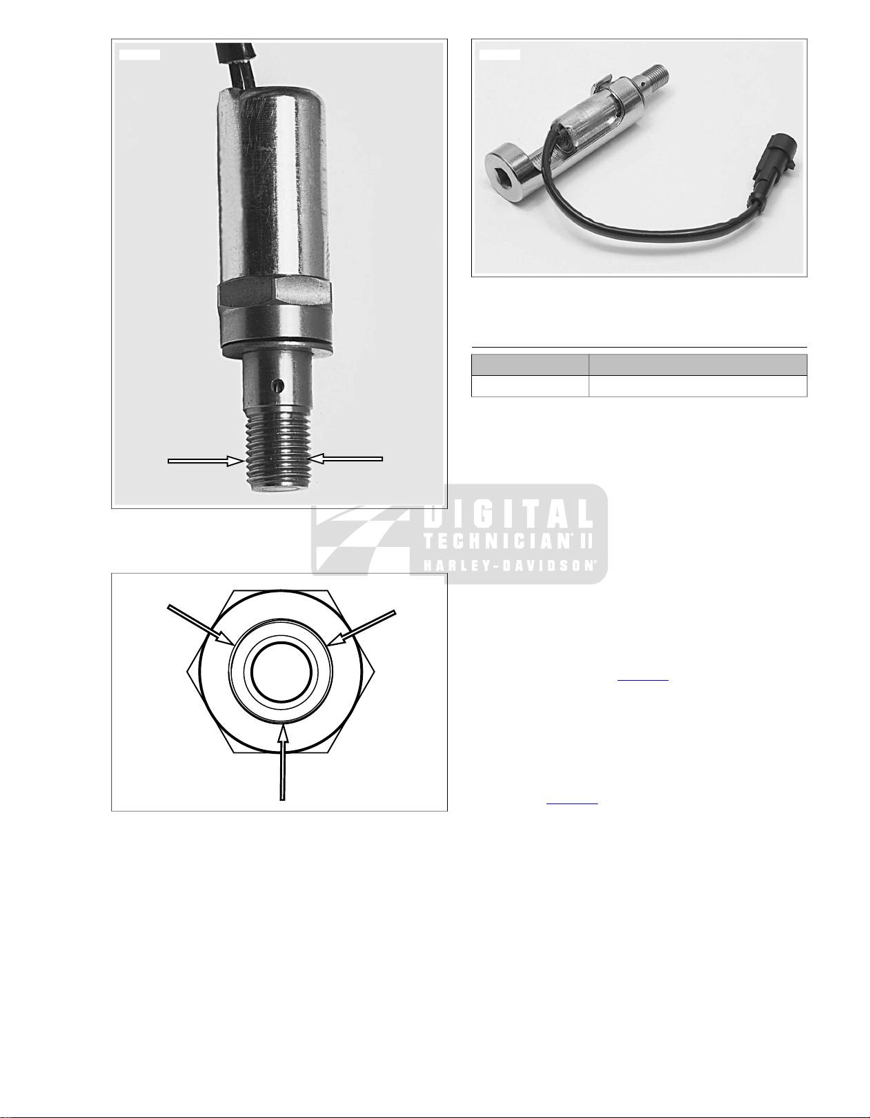
ed01626
ed01627
ed01628
Figure 8-11. Bottom Third
Figure 8-12.Three Dots of Loctite 246 Medium
Strength/High Temperature
Figure 8-13. ACR Solenoid Socket (HD-48498) and ACR
COMPRESSION TEST
TOOL NAMEPART NUMBER
CYLINDER COMPRESSION GAUGEHD-33223-1
A compression test can determine the source of cylinder
leakage. Use CYLINDER COMPRESSION GAUGE (Part
No. HD-33223-1) with a screw-in type adapter.
NOTE
The Twin Cam 103 Engine uses a 12 mm adapter with the
compression gauge.
1. Operate engine to normal operating temperature.
2. Disconnect spark plug wires.
3. Clean around plug base and remove front cylinder spark
plug.
4. Install compression tester to front cylinder per gauge
instructions.
NOTE
The test results will vary depending on whether the ACR is
connected or not. Refer to Table 8-2 for specifications.
5. Shift transmission to neutral. Crank engine continuously
through 5 to 7 compression strokes.
6. Record gauge readings at the end of the first and last
compression strokes (highest readings).
7. Replace front spark plug and repeat test on rear cylinder.
8. Refer to Table 8-2. Readings should be within specified
range. If readings are higher than normal, suspect a
compression release that is not functioning correctly. If
readings are low, inject approximately 1/2 oz. (15 ml)
engine oil into each cylinder and repeat the compression
tests on both cylinders.
NOTE
Readings that are considerably higher after injecting the oil
indicate worn piston rings.
2008 FLT Police Service: Electrical 8-11
Page 72
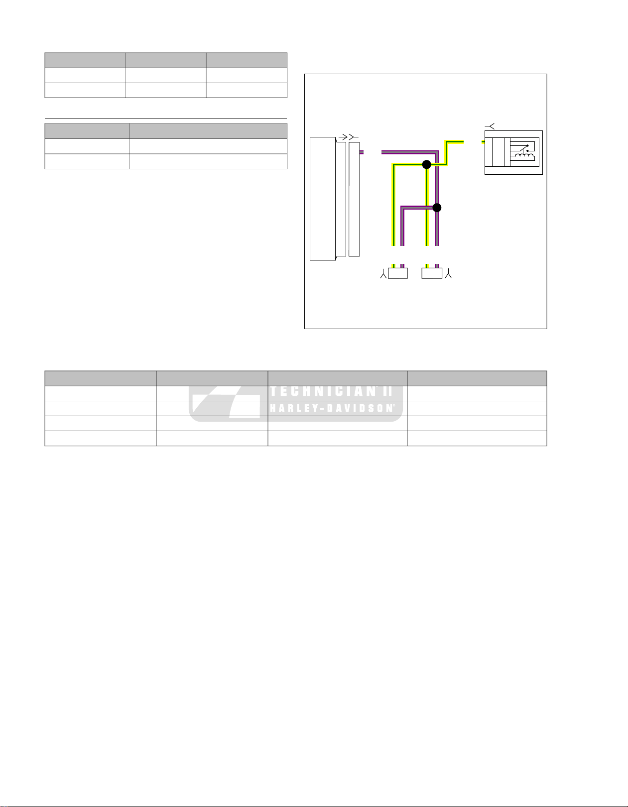
Table 8-2. Compression Specifications
Y/GN
Y/GN
Y/GN
V/GY
V/GY
V/GY
[78A] [78B]
ACR
[119B]
[203FB]
[203RB]
1 2 1 2
19
K 87
5
T 87A
4
E 30
3
SU85
86
2
1
19
em00235
2
PSIACR STATUS
kN/m
896-1,173130-170Connected
1,379-1,517200-220Disconnected
DIAGNOSTICS
TOOL NAMEPART NUMBER
TEST CONNECTOR KITHD-41404-B
BREAK-OUT BOXHD-48637
Diagnostic Tips
Refer to flow charts that follow for troubleshooting.
Diagnostic Notes
NOTE
The step numbers below correlate with the circled numbers in
the flow chart.
1. Use TEST CONNECTOR KIT (P art No. HD-41404-B) with
gray terminal probes and patch cords.
2. Connect BREAK-OUT BOX (P art No. HD-48637) to ECM.
3. If V/GY wire is shorted to ground, the ACRs will remain
on for a time that exceeds the design parameters and the
ACR solenoids will fail.
Figure 8-14. ACR Circuit
Table 8-3. Connectors/Fuse in ACR Circuit
LOCATIONTYPEDESCRIPTIONNUMBER
Under seat73-place DelphiECM[78]
Between cylinders2-place Amp (Tyco)ACR[203F]
Between cylinders2-place Amp (Tyco)ACR[203R]
ESPFI fuse blockLugsSystem relay[119]
8-12 2008 FLT Police Service: Electrical
Page 73

ACR Diagnostics (Part 1 of 2)
Is battery voltage 12.6
VDC or higher?
NO
Charge battery.
Perform starter current draw test while cranking
engine at room temperature. Remove system
relay and repeat starter current draw test.
Is current draw 20-40 Amps greater with
system relay removed?
YES
During the first 2 seconds after turning the
key on (while relay is energized) or while
cranking, measure voltage at terminal “1” on
connector [203FB] (front) or [203RB] (rear).
Is battery voltage present?
Locate and repair open on Y/GN
wire between terminal “1” on
connector [203FB] (front) or
[203RB] (rear) and system relay.
Review symptoms.
Issue is not ACR related.
Measure continuity between
terminal “2” on connector [203FB]
(front) or [203RB] (rear) and
breakout box terminal “19”.
Is continuity present?
Locate and repair open on V/GY wire
between terminal “2” on connector
[203FB] (front) or [203RB] (rear) and
ECM connector [78B] terminal “19”.
Disconnect breakout box from ECM
leaving harness connected to breakout
box. Measure continuity between terminal
“19” on breakout box and ground.
Is continuity present?
Disconnect connector [203FB] (front)
and [203RB] (rear) one at a time.
Is continuity to ground still resent?
Replace grounded
ACR.
Locate and repair short to ground on
V/GY wire between terminal “2” on
connector [203FB] (front) or [203RB]
(rear) and ECM connector [78B}
terminal “19” and replace both ACRs.
NO
YES
YES
YES
NO
YES
NO
YES
NO
NO
1
2
3
fc01777_en
Go to
ACR Diagnostics
(Part 2 of 2).
STOP
7077
7078
7077
7076
2008 FLT Police Service: Electrical 8-13
Page 74
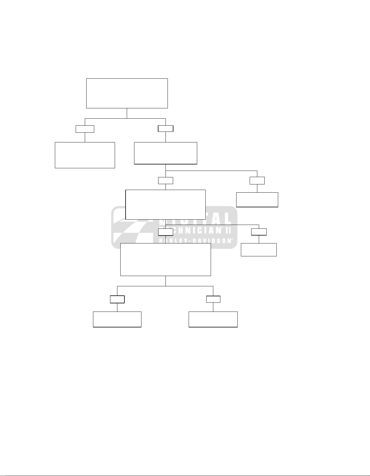
ACR Diagnostics (Part 2 of 2)
Continued from ACR Diagnostics
(Part 1 of 2).
Measure voltage at breakout box terminal “19”
with breakout box disconnected from ECM.
Is voltage present?
Measure resistance between
terminal “1” and “2” on connector
[203FA](front) or [203RA].
Is continuity present?
Reconnect breakout box and ECM; and
ACRs to the engine wiring harness. Measure
voltage at terminal “19” during cranking.
Is voltage 0.1-8.0 VDC and fluctuating while
engine cranks?
Perform compression test (only one spark plug can
be removed at a time or ACR will be disabled).
Refer to COMPRESSION TEST.
Is compression 130 - 170 PSI (896- 1,173 kN/m2 0
with ACR connected and 200-220 PSI (1379-1517
kN/m2) with ACR disconnected?
Review symptoms. Issue
is not ACR related.
Replace ACR on cylinder
that is non-functional.
Locate and repair short to voltage
on V/GY wire between terminal
“2” on connector [203FB] (front)
or [203RB] (rear) and ECM
connector [78B] terminal “19”.
Replace defective
ACR solenoid.
Replace ECM
YES NO
YES
YES
NO
YES
NO
NO
fc01778_en
7079
7077
7080
7077
8-14 2008 FLT Police Service: Electrical
Page 75

SUBJECT............................................................................................................................PAGE NO.
A.1 CONNECTORS........................................................................................................................A-1
A.2 INDEX TO WIRING DIAGRAMS...............................................................................................A-7
APPENDIX A WIRING
Page 76

NOTES
Page 77

[31L]
[167]
[207]
[176]
[31R]
[108]
[21]
[39]
[69]
[24]
[70]
[33]
[32]
[22]
[15]
[2]
[1]
ed01651
A.1CONNECTORS
CONNECTORS
Figure A-1. Inner Fairing
Table A-1. FLHTP Wire Harness Connectors
16-place Molex (black)Main to interconnect harness[1]
2008 FLT Police Service: Appendix A Wiring A-1
LOCATIONTYPEDESCRIPTIONNO.
Inner fairing - right storage box support
bracket
Inner fairing - right fairing support brace12-place Molex (gray)Main to interconnect harness[2]
Upper frame cross member (under seat)4-place DeutschAccessory[4]
Page 78

Table A-1. FLHTP Wire Harness Connectors
16-place Molex (black)Interconnect to right handlebar switches[22]
12-place DeutschTSM/HFSM[30]
4-place MultilockLeft front turn signal/pursuit lamp[31L]
2-place Multilock (black)Front fender tip lamp jumper harness[32]
3-place PackardIgnition/light key switch[33]
2-place DeutschCKP sensor[79]
LOCATIONTYPEDESCRIPTIONNO.
Under left side cover2-place PackardMAXIFUSE[5]
Top of rear fender (under seat)8-place MultilockRear fender lights harness[7]
Inboard of left upper frame tube3-place MultilockRear marker lights harness[12]
Behind fuel tank (under seat)4-place MultilockFuel tank harness[13]
Inner fairing - front of right fairing bracket4-place PackardMain to interconnect harness[15]
Circuit board under tail lamp assembly2-place MultilockLeft rear turn signal[18]
Circuit board under tail lamp assembly2-place MultilockRight rear turn signal[19]
Inner fairing - above storage box10-place MultilockIndicator lights[21]
Inner fairing - fork stem nut lock plate (left
side)
Inner fairing - left fairing support brace12-place Molex (gray)Interconnect to left handlebar switches[24]
Cavity in crossmember at rear of battery
box (under seat)
Inner fairing - outboard of left fairing
bracket
Inner fairing - right fairing support brace4-place MultilockRight front turn signal/pursuit lamp[31R]
Inner fairing - below upper fork bracket
(left side)
Inner fairing - under storage box (front of
ignition switch housing)
Inner fairing (back of headlamp)Headlamp ConnectorHeadlamp[38]
Inner fairing (back of speedometer)12-place Packard (black)Speedometer[39]
Circuit board under tail lamp assembly3-place MultilockRear fender tip lamp[45]
Bottom of voltage regulator (left side)3-place LyallStator[46]
Top rail of engine guard (right side)2-place DeutschSiren/PA speaker[57]
Under luggage rack (left side)2-place DeutschRear pole lamp[59]
Under left side coverPackardFuse block[64]
Top of transmission case (under Starter)3-place DelphiVSS[65]
Inner fairing - front of speedometerRelay connectorPursuit flasher (domestic only)[69]
Inner fairing - left fairing support brace12-place Deutsch (black)Siren amplifier harness[70]
Top rail of saddlebag guard (left side)18-place PackardSiren amplifier[72]
Bottom of voltage regulator (right side)2-place LyallVoltage regulator[77]
Under right side cover73-place PackardECM[78]
Electrical caddy at bottom of lower frame
crossmember
Top of induction module3-place PackardMAP sensor[80]
Below fuel tank (left side)4-place DelphiIgnition coil[83]
Below fuel tank (left side)2-place DelphiFront injector[84]
Below fuel tank (left side)2-place DelphiRear injector[85]
Below fuel tank (right side)4-place DelphiIAC[87]
Below fuel tank (right side)3-place DelphiTP sensor[88]
Below fuel tank (right side)2-place DelphiIAT sensor[89]
Back of front cylinder (left side)2-place DelphiET sensor[90]
Under right side cover4-place DeutschData link[91]
Circuit board under tail lamp assembly4-place MultilockTail lamp[93]
Circuit board under tail lamp assembly6-place MultilockRear fender lights harness to circuit board[94]
A-2 2008 FLT Police Service: Appendix A Wiring
Page 79

Table A-1. FLHTP Wire Harness Connectors
12-place MultilockFairing cap switches[105]
Relay connectorIgnition keyswitch relay[126]
3-place Molex (black)Jiffy Stand Sensor[133]
2-place Amp (Tyco)O2 sensor front exhaust header[138]
2-place Amp (Tyco)Front wheel speed sensor[167]
6-place DeutschMain to interconnect harness[176]
5-place Amp (Tyco)Active exhaust actuator[179]
LOCATIONTYPEDESCRIPTIONNO.
Inner fairing - above upper fork bracket
(right side)
Inner fairing (back of tachometer)12-place Packard (gray)Tachometer[108]
Inner fairing (back of voltmeter)Spade connectorVoltmeter lamp[110]
Inner fairing (back of voltmeter)Spade connectorVoltmeter[111]
Inner fairing (back of fuel gauge)Spade connectorFuel gauge lamp[116]
Inner fairing (back of fuel gauge)Spade connectorFuel gauge[117]
Fuse block (under right side cover)Fuse terminalsEFI fuses[119]
Bottom of rear frame downtube (right side)Spade terminalsRear brake light switch[121]
Between cylinders (left side)Spade terminalsHorn[122]
Fuse block (under left side cover)Relay connectorStarter relay[123]
Fuse block (under left side cover)Relay connectorBrake light relay[124]
Cavity in crossmember at rear of battery
box (under seat)
Top of starterSpade terminalsStarter solenoid[128]
Upper frame cross member (under seat)Ring terminalsHarness grounds[129]
Top of transmission (right side)Post terminalsNeutral switch[131]
Inner fairing (left side)Spade terminalsCigarette lighter[132]
HDI: Electrical caddie at bottom of lower
frame crossmember. (Not used on
Domestic)
Fuse block (under right side cover)Relay connectorEFI system relay[135]
Under chrome starter cover2-place Amp (Tyco)O2 sensor rear exhaust header[137]
Back of cross brace between front frame
downtubes (left side)
Front right crankcase4-place DelphiOil pressure sender[139]
Top of canopy (under console)4-place PackardFuel level sender and fuel pump[141]
Inner fairing - right fairing support brace6-place DeutschMain to interconnect harness[156]
Upper frame cross member (under seat)1-place PackardB+[160]
Under right side cover20-place MolexABS module[166]
Inner fairing - below upper fork bracket
(left side)
Under right side cover2-place Amp (Tyco)Rear wheel speed sensor[168]
Inner fairing - outboard of right fairing
bracket
Back of air cleaner backplate2-place Amp (Tyco)Active intake solenoid[178]
Domestic (not used): under right side
cover
HDI: under right side cover (behind electrical bracket)
Under right side cover4-place DeutschABS diode pack[201]
Between cylinders2-place Amp (Tyco)ACR solenoid[203F]
Between cylinders2-place Amp (Tyco)ACR solenoid[203R]
Inner fairing, right support bracket6-place MolexTwist Grip sensor[204]
Inner fairing - front of right fairing bracket3-place Molex (black)Stealth (disable lighting circuit)[207]
Throttle body6-place MolexThrottle Control Actuator[211]
2008 FLT Police Service: Appendix A Wiring A-3
Page 80
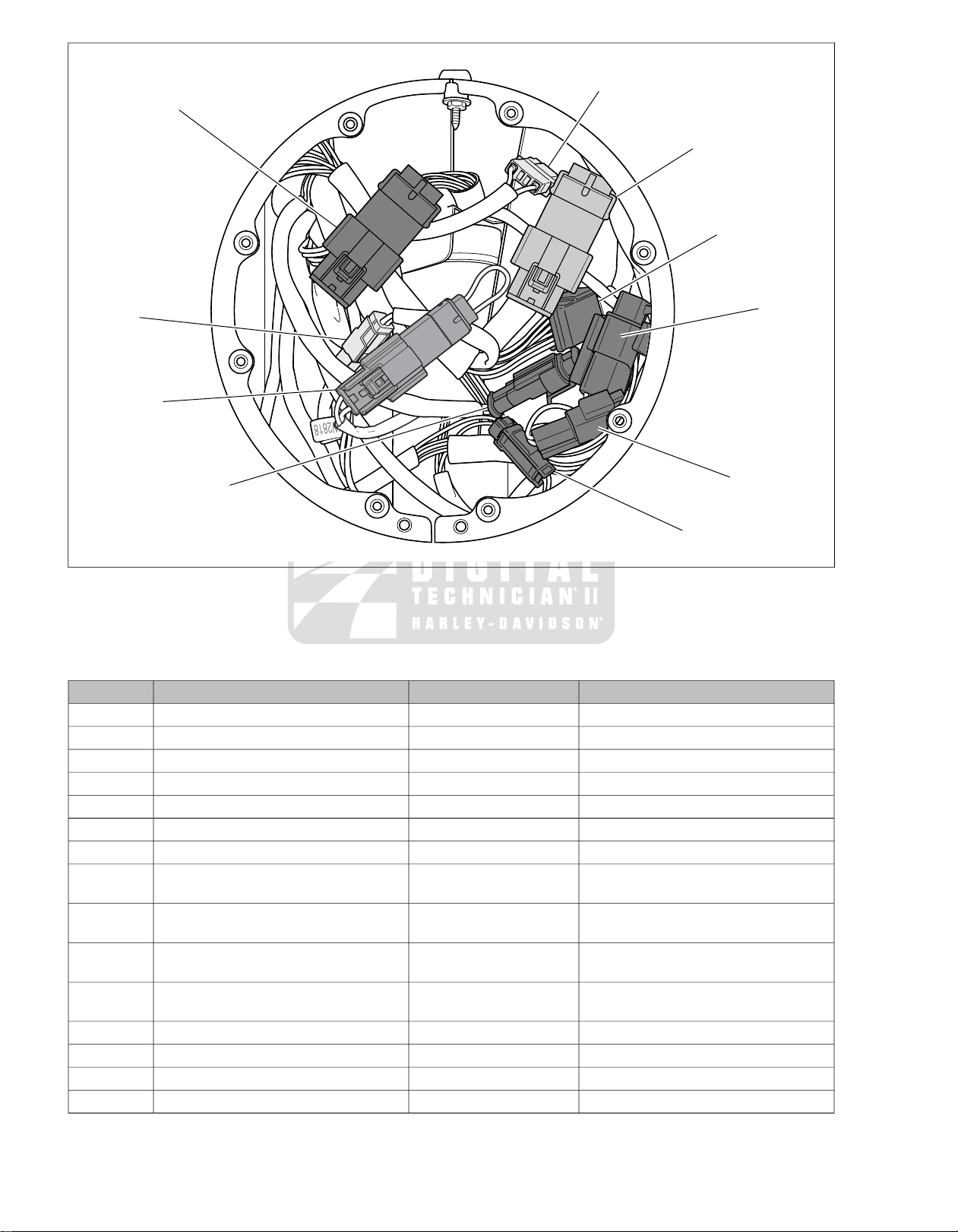
[67]
[24]
[73]
[22]
[31]
[20]
[32]
[177]
[167]
[207]
ed01652
Figure A-2. Headlamp Nacelle (FLHP/E)
Table A-2. FLHP/E Wire Harness Connectors
12-place MolexRight handlebar switches[22]
12-place MolexLeft handlebar switches[24]
12-place DeutschTSM/HFSM[30]
6-place MultilockFront turn signals[31]
LOCATIONTYPEDESCRIPTIONNO.
Upper frame cross member (under seat)4-place DeutschAccessory[4]
Under left side cover2-place PackardMAXIFUSE[5]
Top of rear Fender (under seat)8-place MultilockRear fender lights harness[7]
Circuit board under tail lamp assembly2-place MultilockLeft rear turn signal[18]
Circuit board under tail lamp assembly2-place MultilockRight rear turn signal[19]
Inside headlamp nacelle6-place DeutschTachometer harness[20]
Under console8-place DeutschIndicator lamps[21]
Inside headlamp nacelle - fork stem nut
lock plate (right side)
Inside headlamp nacelle - fork stem nut
lock plate (left side)
Cavity in crossmember at rear of battery
box (under seat)
Inside headlamp nacelle - fork stem nut
lock plate (left side)
Inside headlamp nacelle2-place Multilock (black)Front fender tip lamp jumper harness[32]
Under console3-place PackardIgnition/light key switch[33]
Inside headlamp nacelleHeadlamp connectorHeadlamp[38]
Back of speedometer (under console)12-place PackardSpeedometer[39]
A-4 2008 FLT Police Service: Appendix A Wiring
Page 81

Table A-2. FLHP/E Wire Harness Connectors
2-place DeutschCKP sensor[79]
Relay connectorIgnition keyswitch relay[126]
3-place Molex (black)Jiffy Stand Sensor[133]
2-place Amp (Tyco)O2 sensor front exhaust header[138]
LOCATIONTYPEDESCRIPTIONNO.
Circuit board under tail lamp assembly3-place MultilockRear fender tip lamp[45]
Bottom of voltage regulator (left side)3-place LyallStator[46]
Top rail of engine guard (right side)2-place DeutschSiren/PA speaker[57]
Under luggage rack (left side)2-place DeutschRear pole lamp[59]
Under left side coverPackardFuse block[64]
Top of transmission case (under Starter)3-place DelphiVSS[65]
Inside headlamp nacelle4-place AmpAccessory switch[67]
Inside headlamp nacelleRelay connectorPursuit flasher (domestic only)[69]
Top rail of saddlebag guard (left side)18-place PackardSiren amplifier[72]
Inside headlamp nacelle2-place Multilock (white)Pursuit lamps[73]
Bottom of voltage regulator (right side)2-place LyallVoltage regulator[77]
Under right side cover73-place PackardECM[78]
Electrical caddy at bottom of lower frame
crossmember
Top of induction module3-place PackardMAP sensor[80]
Below fuel tank (left side)4-place DelphiIgnition coil[83]
Below fuel tank (left side)2-place DelphiFront injector[84]
Below fuel tank (left side)2-place DelphiRear injector[85]
Below fuel tank (right side)4-place DelphiIAC[87]
Below fuel tank (right side)3-place DelphiTP sensor[88]
Below fuel tank (right side)2-place DelphiIAT sensor[89]
Back of Front Cylinder (left side)2-place DelphiET sensor[90]
Under right side cover4-place DeutschData link[91]
Circuit board under tail lamp assembly4-place MultilockTail lamp[93]
Circuit board under tail lamp assembly6-place MultilockRear fender lights harness to circuit board[94]
Back of tachometer12-place Packard (gray)Tachometer[108]
Below fuel tank (left side)4-place MultilockFuel gauge[117]
Fuse block (under right side cover)Fuse terminalsEFI fuses[119]
Front Right CrankcasePost terminalOil pressure switch[120]
Bottom of rear frame downtube (right side)Spade terminalsRear brake light switch[121]
Between cylinders (left side)Spade terminalsHorn[122]
Fuse Block (under left side cover)Relay connectorStarter relay[123]
Fuse Block (under left side cover)Relay connectorBrake light relay[124]
Cavity in crossmember at rear of battery
box (under seat)
Top of starterSpade terminalsStarter solenoid[128]
Upper frame cross member (under seat)Ring terminalsHarness grounds[129]
Top of transmission (right side)Post terminalsNeutral switch[131]
HDI: Electrical caddie at bottom of lower
frame crossmember. (Not used on
Domestic)
Fuse block (under right side cover)Relay connectorEFI system relay[135]
Under chrome starter cover2-place Amp (Tyco)O2 sensor rear exhaust header[137]
Back of cross brace between front frame
downtubes (left side)
Top of canopy (under console)4-place PackardFuel level sender and fuel pump[141]
2008 FLT Police Service: Appendix A Wiring A-5
Page 82
Table A-2. FLHP/E Wire Harness Connectors
5-place Amp (Tyco)Active exhaust actuator[179]
LOCATIONTYPEDESCRIPTIONNO.
Under front fender tip lamp bracket2-place Multilock (black)Front fender tip lamp (DOM)[143]
Upper frame cross member (under seat)1-place PackardB+[160]
Under right side cover20-place MolexABS module[166]
Inside headlamp nacelle (left side)2-place Amp (Tyco)Front wheel speed sensor[167]
Under right side cover2-place Amp (Tyco)Rear wheel speed sensor[168]
Inboard of left upper frame tube3-place MultilockRear marker lights harness[173]
Under left side cover (beneath harness)4-place DeutschMain to main harness[176]
Back of air cleaner backplate2-place Amp (Tyco)Active intake solenoid[178]
Domestic (not used): under right side
cover
HDI: under right side cover (behind electrical bracket)
Inside headlamp nacelle (left side)2-place DeutschMain to main harness[177]
Under right side cover4-place DeutschABS diode pack[201]
Between cylinders2-place Amp (Tyco)ACR solenoid[203F]
Between cylinders2-place Amp (Tyco)ACR solenoid[203R]
Inside Headlamp Nacelle6-place MolexTwist Grip sensor[204]
Inside headlamp nacelle3-place MolexStealth (disable lighting circuit)[207]
Throttle body6-place MolexThrottle Control Actuator[211]
Under the seat4-place PackardIgnition switch interconnect[222]
A-6 2008 FLT Police Service: Appendix A Wiring
Page 83
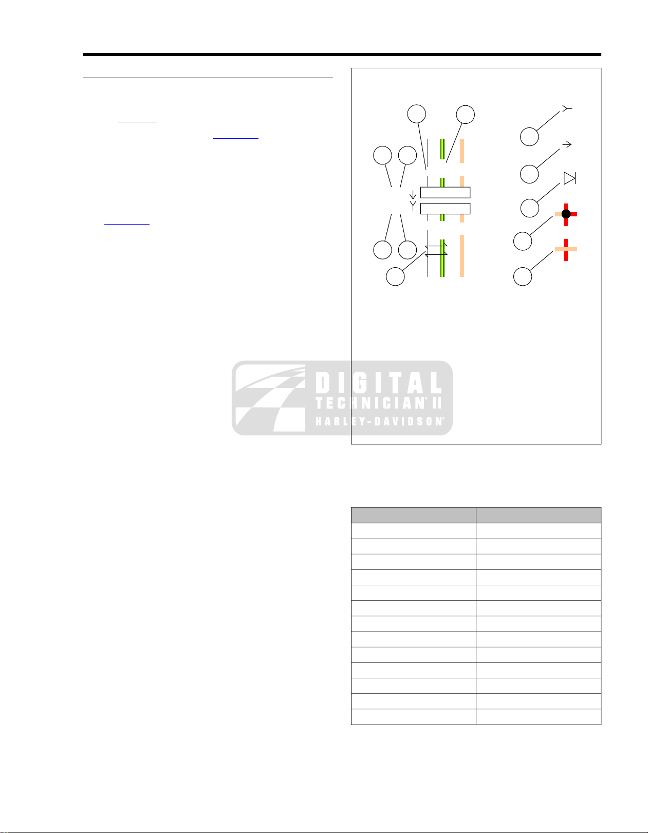
WIRING DIAGRAM INFORMATION
910
1 2
1 2
8
7
6
5
3
4
TN
TN
W
W
GN/Y
GN/Y
1 2 4
1 2 4
[21A]
[21B]
ed01269
Wire Color Codes
Wire traces on wiring diagrams are labeled with alpha codes.
Refer to Table A-3.
For Solid Color Wires: See Figure A-3. The alpha code
identifies wire color (3).
For Striped Wires:The code is written with a slash (/) between
the solid color code and the stripe code (4). For example, a
trace labeled GN / Y is a green wire with a yellow stripe.
Wiring Diagram Symbols
See Figure A-3. On wiring diagrams and in service/repair
instructions, connectors are identified by a number in brack ets
(1). The letter (2) inside the brackets identifies whether the
housing is a socket or pin housing.
A=Pin: The letter A after a connector number and the pin
symbol (6) identifies a pin housing.
B=Socket: The letter B after a connector number and the
socket symbol (5) identifies a socket housing.
Other symbols found on the wiring diagrams include the symbol
for a diode (7), a symbol for a wire-to-wire connection (8), a
symbol that verifies that no connection (9) between two wire
traces exists and a symbol identifying two wires that are twisted
together (10).
A.2INDEX TO WIRING DIAGRAMS
1. Connector number
2. Terminal code (A=pin, B=socket)
3. Solid wire color
4. Striped wire color
5. Socket symbol
6. Pin symbol
7. Diode
8. Connection
9. No connection
10. Twisted pair
Figure A-3. Connector/Wiring Diagram Symbols (typical)
Table A-3.Wire Color Codes
WIRE COLORALPHA CODE
BlueBE
BlackBK
BrownBN
GreenGN
GreyGY
Light GreenLGN
OrangeO
PinkPK
RedR
TanTN
VioletV
WhiteW
YellowY
2008 FLT Police Service: Appendix A Wiring A-7
Page 84
WIRING DIAGRAMS
Wiring Diagram List
Fender Tip Lamps
Cap Switches and HFSM Antenna
and Strobe Harness
T ail Lamp , Pursuit Lamps, Directional Lamps, Accessory/Spot Switch, Speedometer , Tachometer and HFSM
Antenna
LOCATIONDIAGRAM
Figure A-42008 FLHTP, DOMESTIC and INTERNATIONAL Models, Main Harness without ABS (1 of 2)
Figure A-52008 FLHTP, DOMESTIC and INTERNATIONAL Models, Main Harness with ABS (1 of 2)
Figure A-62008 FLHTP, DOMESTIC and INTERNATIONAL Models, Main Harness (2 of 2)
Figure A-72008 FLHTP, DOMESTIC and INTERNATIONAL Models, Interconnect Harness
Figure A-82008 FLHTP, DOMESTIC and INTERNATIONAL Models, Pursuit Lamps, Directional Lamps, Tail Lamp and
Figure A-92008 FLHTP, DOMESTIC and INTERNATIONAL Models, Starting and Charging
Figure A-102008 FLHTP, DOMESTIC and INTERNATIONAL Models, Handlebar Switches, Indicator Lamps, Fairing
Figure A-112008 FLHTP, DOMESTIC and INTERNATIONAL Models, Anti-Lock Brake System (ABS) Siren Amplifier
Figure A-122008 FLHP and FLHPE, DOMESTIC and INTERNATIONAL Models, Main Harness without ABS (1 of 2)
Figure A-132008 FLHP and FLHPE, DOMESTIC and INTERNATIONAL Models, Main Harness with ABS (1 of 2)
Figure A-142008 FLHP and FLHPE, DOMESTIC and INTERNATIONAL Models, Main Harness (2 of 2)
Figure A-152008 FLHP and FLHPE, DOMESTIC and INTERNATIONAL Models, Starting and Charging
Figure A-162008 FLHP and FLHPE, DOMESTIC and INTERNATIONAL Models, Handlebar Switches, Indicator Lamps,
Figure A-172008 FLHTP, FLHP and FLHPE, DOMESTIC and INTERNATIONAL Models, Optional Strobe System
A-8 2008 FLT Police Service: Appendix A Wiring
Page 85
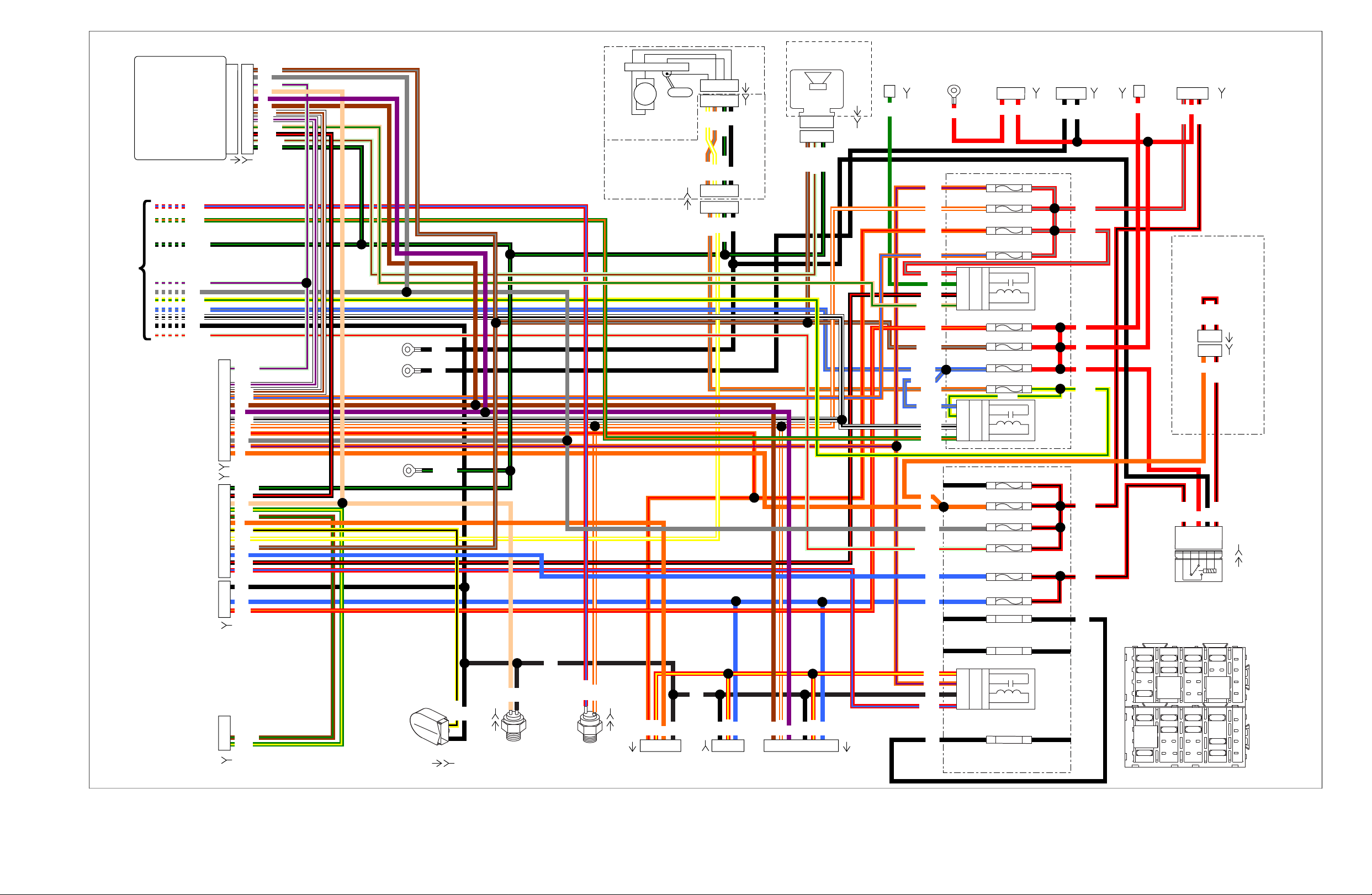
B A
Turn Signal/
Turn Signal Security
Module
To Main Harness Page 2
To
Fairing
Harness
To
Fairing
Harness
To
Fairing
Harness
[15B]
[2B]
[1B]
Front GND
Stud
(Dirty)
Rear GND
Stud
(Clean)
Fuel Pump
Assembly Intank
[141A]
[13B]
[13A]
A B C D
A B C D
1 2 334
Power
Signal
Ground
Optional
Security
Siren
Start
Solenoid
[142A]
[142B]
[128B]
1 2 3
1 2 3
GN
BK/GN
BN/GY
LGN/BN
1 2 4
Fuel
Pump
[GND1]
[GND2]
[GND1A]
BK/GN
BK
BK
[139B]
B
A
B
D
1
1
2
3
4
5
6
7
8
9
10
11
13
2
3
4
5
6
7
8
9
10
11
12
A
Oil
Pressure
Sender
[30A] [30B]
(GY)
Battery 1 1
Ignition 2 2
Serial Data
3 3
Neutral Switch
4 4
Left Turn Feed
5 5
Right Turn Feed
6 6
Right Turn SW Input
7 7
Left Turn SW Input
8 8
Start Relay Control
9 9
Clutch Switch
10 10
Alarm Signal
11 11
Ground
12 12
GY
TN
BN
GY
BK
BN
BK
BK
BK
GY
TN
BE
BE
W/V
O/W
O/R
R/O
Y/W
Y/W
Y/W
O/V
W/V
V
V
O
O
LGN/BN
LGN/V
BN/GY
BK/GN
BK/GN
BE/GY
BK/GN
BK/GN
BK/GN
BN/GN
BN/GY
BN/GN
TN/GN
LGN/V
LGN/V
LGN/R
W/BN
GN/O
R/BE
W/BK
Y/BK
BK/R
BK/R
GN/Y
GN/Y
W/BN
O/GY
BK
Y/W
BK/GN
O/GY
O/GY
R/BE
O/BE
BK/R
Y/GN
W/BK
To Rear LightingTour-Pak
Accessory
Connector
Rear
Stop Light
Switch
Neutral
Switch
Horn
[7A]
[12B]
(BK)
[4A]
[122]
1 2 31
112
2
2 3 3 2 14 5 6 7
BK
BK
BK
BK
BKBNBE
BE
BK
BK
TN
O/W
O/W
R/Y
R/Y
O/R
R/Y
O
V
Y/BK
R/BE
Main Power
at Starter
40 Amp
MAXIFUSE
Voltage
Regulator
Ignition
SwitchB+
Connector
[BATT]
[5B] [77B]
[160B]
[33B]
A B
1 2 3
1 2
R/GY
R/BK
BK
BK
R
R
R
R
R
[126B]
Lighting
Relay
Police Stealth
[207A]
[207B]
[126A]
87(5)
30(3)
85(2)
86(1)
87A(4)
BK
R
O
R/BK
R/BK
R/BK
R/BK
R/BK
1
Amber cap removed
when stealth switch
option is used
3
1 3
Start
Relay
System
Relay
Brake
Relay
Cruise/Brake - 15A1B 1A
Accessory - 15A1D 1C
Battery - 15A2D 2C
Radio Memory - 15A2B 2A
ECM Power - 15A2F 2E
Fuel Pump - 15A4B 4A
P & A - 15A1B 1A
INSTRS - 15A1D 1C
Ignition - 15A1F 1E
Engine CNTRL - 15A1H 1G
Headlamp - 15A2D 2C
Lights - 15A
Spare - 15A
Spare - 30A
Spare - 30A
(ABS Only)
2F 2E
4B 4A
3H 3G
4H 4G
P & A - 15A
Radio Power/
Siren - 15A
1F
1H
3H
4G
4H
3G
30
87
86
85
3
5
1
2
3D
4C
4D
3C
30
87
86
85
3
5
1
2
2B
3A
3B
2A
30
87
86
85
3
5
1
2
1E
1G
BK
BE
GN
BE
GY
BK
BK
O/V
O/R
R/O
O/W
O/V
R/Y
R
R
R
O
O
TN/GN
BE/GY
BE/GY
BE/GY
BN/GY
LGN/R
O/GY
W/BK
GN/O
Y/GN
Y/GN
BK/R
R/GY
O/BE
R/GY
R/GY
R/BE
R/BK
R/BK
15A
15A
1
2
3
4
1
15A
A
B
D
F
H
B D F H
C E G J
A C E G J
15A 15A
15A
15A
15A
15A
15A
30A
15A
15A
85
31579-04
12VOC
30
87 86
85
31579-04
12VOC
30
87 86
[33A]
[12A]
[121]
[131]
[139A]
[15A]
[2A]
(GY)
[1A]
(BK)
15A
15A
15A
1
2
3
4
B
30A
85
31579-04
12VOC
30
87 86
[141B]
et00067
Figure A-4. 2008 FLHTP, DOMESTIC and INTERNATIONAL Models, Main Harness without ABS (1 of 2)
Page 86

Figure A-4.Figure A-4.
2008 FLHTP, DOMESTIC and INTERNATIONAL Models, Main
Harness without ABS (1 of 2)
2008 FLHTP, DOMESTIC and INTERNATIONAL Models, Main
Harness without ABS (1 of 2)
Page 87
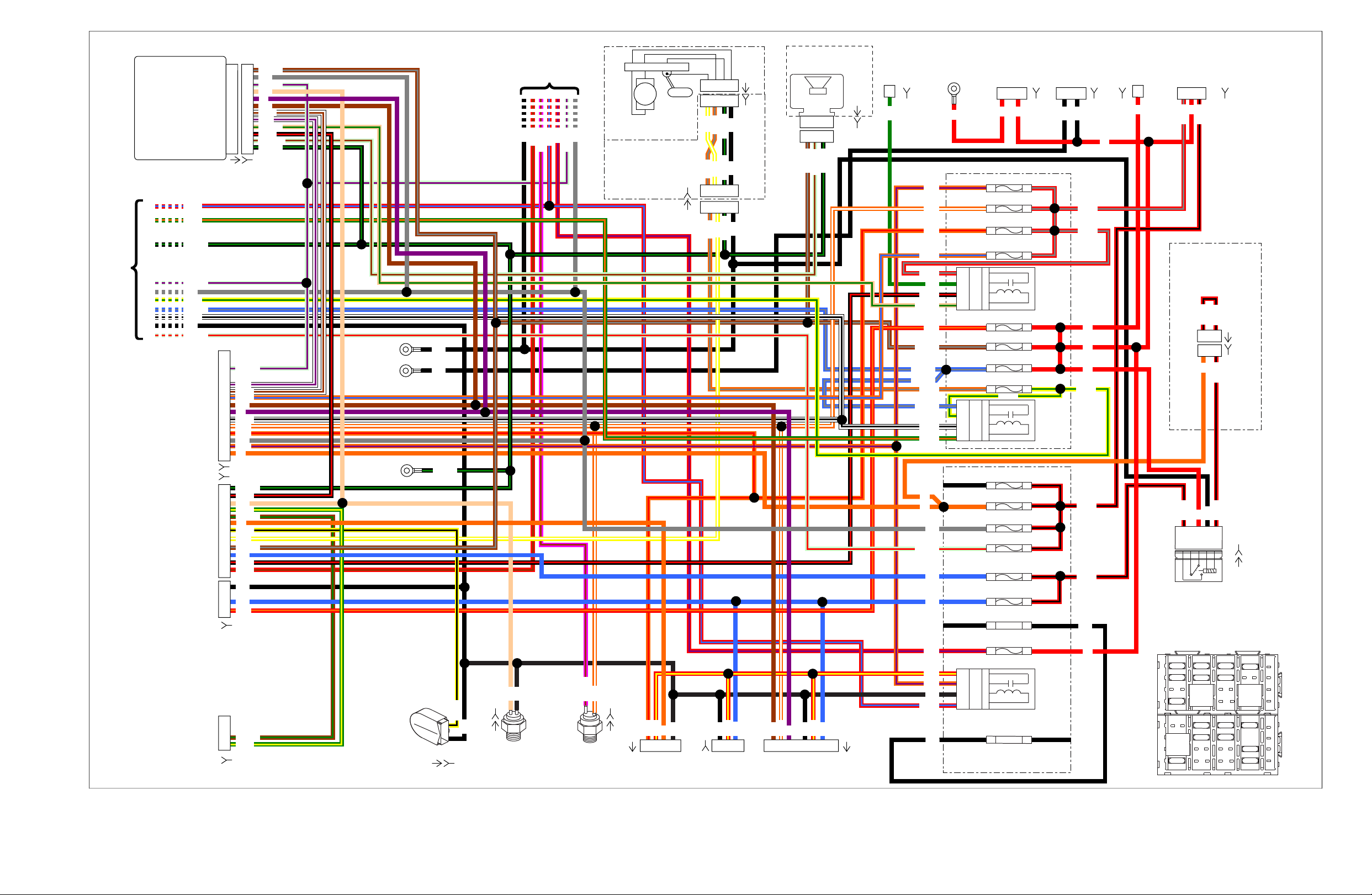
B A
Turn Signal/
Turn Signal Security
Module
To Main Harness Page 2
To ABS
To
Fairing
Harness
To
Fairing
Harness
To
Fairing
Harness
[15B]
[2B]
[1B]
Front
GND
Stud
(Dirty)
Rear GND
Stud
(Clean)
Fuel Pump
Assembly Intank
[141A]
[141B]
[13B]
[13A]
A B C D
A B C D
1 2 334
Power
Signal
Ground
Optional
Security
Siren
Start
Solenoid
[142A]
[142B]
[128B]
1 2 3
1 2 3
GN
BK/GN
BN/GY
LGN/BN
1 2 4
Fuel
Pump
[GND1]
[GND2]
[GND1A]
BK/GN
BK
BK
[139B]
B
A
B
D
1
1
2
3
4
5
6
7
8
9
10
11
13
2
3
4
5
6
7
8
9
10
11
12
A
Oil
Pressure
Sender
[30A] [30B]
Battery 1 1
Ignition 2 2
Serial Data
3 3
Neutral Switch
4 4
Left Turn Feed
5 5
Right Turn Feed
6 6
Right Turn SW Input
7 7
Left Turn SW Input
8 8
Start Relay Control
9 9
Clutch Switch
10 10
Alarm Signal
11 11
Ground
12 12
GY
TN
BN
BK
GY
GY
BK
BN
BK
BK BK
GY
TN
BE
BE
W/V
O/W
O/R
R/O
Y/W
Y/W
Y/W
O/V
W/V
R/V
V
V
O
O
LGN/BN
LGN/V
BN/GY
PK/BN
LGN/V
BK/GN
BE/GY
BK/GN
BK/GN
BK/GN BK/GN
BN/GN
BN/GY
BN/GN
PK/BN
TN/GN
LGN/V
LGN/V
LGN/R
W/BN
GN/O
R/BE
W/BK
Y/BK
BK/R
BK/R
GN/Y
GN/Y
W/BN
R/BN
R/BE
O/GY
BK
Y/W
BK/GN
O/GY
O/GY
R/BN
O/BE
BK/R
Y/GN
W/BK
To Rear LightingTour-PakAccessory
Connector
Rear
Stop Light
Switch
Neutral
Switch
Horn
[7A]
[12B]
(BK)
[4A]
[122]
1 2 31
112
2
2 3 3 2 14 5 6 7
BK
BK
BKBNBE
BK
BK
TN
O/W
O/W
R/Y
R/Y
O/R
R/Y
O
BE
V
Y/BK
Main Power
at Starter
40 Amp
MAXIFUSE
Voltage
Regulator
Ignition Switch
B+
Connector
[BATT]
[5B] [77B]
[160B]
[33B]
A B
1 2 3
1 2
R/GY
R/BK
BK
BK
R
R
R
R
R
R
[126B]
Lighting
Relay
Police Stealth
[207A]
[207B]
87(5)
30(3)
85(2)
86(1)
87A(4)
BK
R
O
R/BK
R/BK
R/BK
R/BK
R/BK
1
Amber cap removed
when stealth switch
option is used
3
1 3
Start
Relay
System
Relay
Brake
Relay
Spare 30A
Spare 15A
Cruise/Brake - 15A1B 1A
Accessory - 15A1D 1C
Battery - 15A2D 2C
Radio Memory - 15A2B 2A
ECM Power - 15A2F 2E
Fuel Pump - 15A4B 4A
P & A - 15A1B 1A
INSTRS - 15A1D 1C
Ignition - 15A1F 1E
Engine CNTRL - 15A1H 1G
Headlamp - 15A2D 2C
Lights - 15A2F 2E
4B 4A
3H 3G
4H 4G
P & A - 15A
Radio Power/
Siren - 15A
1F
1H
3H
4G
4H
3G
30
87
86
85
3
5
1
2
3D
4C
4D
3C
30
87
86
85
3
5
1
2
2B
3A
3B
2A
30
87
86
85
3
5
1
2
1E
1G
BK
BE
GN
BE
GY
BK
BK
O/V
O/R
R/O
O/W
O/V
R/Y
R/V
R
R
R
R
O
O
TN/GN
BE/GY
BE/GY
BE/GY
BN/GY
LGN/R
O/GY
W/BK
GN/O
Y/GN
Y/GN
BK/R
R/GY
O/BE
R/GY
R/GY
R/BE
R/BK
R/BK
ABS - 30 A
15A
15A
15A
1
2
3
4
1
2
3
4
15A
A
B
D
F
H
B D F H
C E G J
A C E G J
15A 15A
15A
15A
15A
15A
15A
15A
30A 30A
15A
15A
85
31579-04
12VOC
30
87 86
85
31579-04
12VOC
30
87 86
85
31579-04
12VOC
30
87 86
[33A]
[12A]
[121]
[131]
[15A]
[139A]
[2A]
(GY)
[1A]
(BK)
et00068
Figure A-5. 2008 FLHTP, DOMESTIC and INTERNATIONAL Models, Main Harness with ABS (1 of 2)
Page 88

Figure A-5.Figure A-5.
2008 FLHTP, DOMESTIC and INTERNATIONAL Models, Main
Harness with ABS (1 of 2)
2008 FLHTP, DOMESTIC and INTERNATIONAL Models, Main
Harness with ABS (1 of 2)
Page 89

[78A] [78B]
[91A]
[90A]
[90B]
[179B] [95B] [138B] [137B] [65B] [133B] [203FB] [203RB]
[204B]
[204A]
[83A]
[83B]
[85A]
[85B]
[84A]
[84B]
[80A]
[80B]
[211A]
[211B]
[79A]
[79B]
From Main Harness Page 1
(GY)
ECM
21
23
24
25
28
29
30
33
36
37
38
39
40
43
46
49
50
51
52
53
54
56
59
61
62
63
64
66
68
69
73
Exhaust Actuator
Rear Injector
TMAP Sensor Input
Brake Switch
Front Injector
Twist Grip High
Twist Grip Low
Ion Sense
Throttle Pos. Sensor 2
Throttle Pos Sensor 1
Exhaust Feedback
Twist Grip Sensor 2
VehicleSpeed Input
Crank Position Sensor (-)
Rear O2Sensor (Unheated)
Twisted
Pair
Intake Air Temperature
5V Sensor Power 1
Engine Temperature
12 V Power
Rear Coil
Front Coil
Jiffy Stand Sensor
Twist Grip Sensor 1
5V Sensor Ground 1
5V Sensor Ground 2
Crank Position Sensor (+)
VehicleSpeed Ground
Front O2Sensor (Unheated)
5V Sensor Power 2
Serial Data
Ground
21
22Cruise/Set/Coast 22
20
1 2 3 4
A B
A B A B
A B A B
C D
A B C D
1 2 3 4 5 6
1 2 3 4 5 6
1 2 3 4 5 6
Purge Solenoid 20
19ACR 19
23
24
25
28
27System Relay Enable 27
29
30
33
34Cruise Resume/Accelerate 34
35Cruise Enable 35
36
37
38
39
40
43
46
49
50
51
52
53
54
56
59
61
62
63
64
66
68
69
71
12V Battery 71
72
12V Run/Stop Switch 72
73
5 B A 1 2 1 2 1 2 3 1 2 34 3 2 1
Data Link
Connector
Engine Temp
Sensor
Twist Grip
Sensor
Ignition
Coil
BK
R
Crank Pos.
Sensor
1 2
1 2
A B
A B
Power
Ion Sense
Coil Rear
Coil Front
Rear
Injector
Front
Injector
TMAP
Sensor
1 2 3 4
1 2 3 4
Throttle Control
Actuator
6 5 4 3 2 1
6 5 4 3 2 1
Active
Exhaust
(HDI Only)
Purge
Solenoid
Jiffy Stand
Sensor
(HDI Only)
1 2
Rear
ACR
1 2
Front
ACR
Vehicle
Speed
Sensor
Front
O2Sensor
Rear
O2Sensor
GY
V/O
V/W
V/Y
R/W
R/W
V/W
W/Y
R/W
V/O
W/Y
V/Y
BK/PK
GY/BE
GY/BE
GN/GY
LGN/Y
GN/BN
LGN/V
LGN/R
PK/GN
GN/BN
BK/GN
BE/BK
PK/GN
BE/GN
BK/GY
BK/GN
BE/GY
GN/GY
R/BE
R/GN
BN/V
PK/Y
Y/BE
BK/W
W/BK
PK/O
V/BE
GY/Y
PK/O
BK/W
BK/W
W/GN
BN/O
BN/O
BK/Y
Y/GN
Y/GN
Y/GN
+BK
GY/Y
BK/O
PK/Y
BK/W
BK/W
Y/GN
Y/BE
Y/GN
Y/GN
BN/V
BN/O
BN/R
BK/O
BK/W
BE/O
BN/O
W/BE
W/GN
BN/O
Y/GN
BE/O
BK/Y
BN/R
V/BE
GN/O
R
BK
LGN/V
BK/GN
BE/GN
BK/GY
LGN/Y
BK/GY
BK/PK
BE/BK
BK/GN
LGN/V
R/BE
GN/O
W/BE
R/GN
Y/GN
GY
LGN/R
BE/GY
W/BK
BK
Yellow Tubing
Black Tubing
R
R
R
R
W
W
W
W
BK
BK
BK
BK
V/GY
V/GY
V/GY
et00097
Figure A-6. 2008 FLHTP, DOMESTIC and INTERNATIONAL Models, Main Harness (2 of 2)
Page 90

Figure A-6.Figure A-6.
2008 FLHTP, DOMESTIC and INTERNATIONAL Models, Main
Harness (2 of 2)
2008 FLHTP, DOMESTIC and INTERNATIONAL Models, Main
Harness (2 of 2)
Page 91
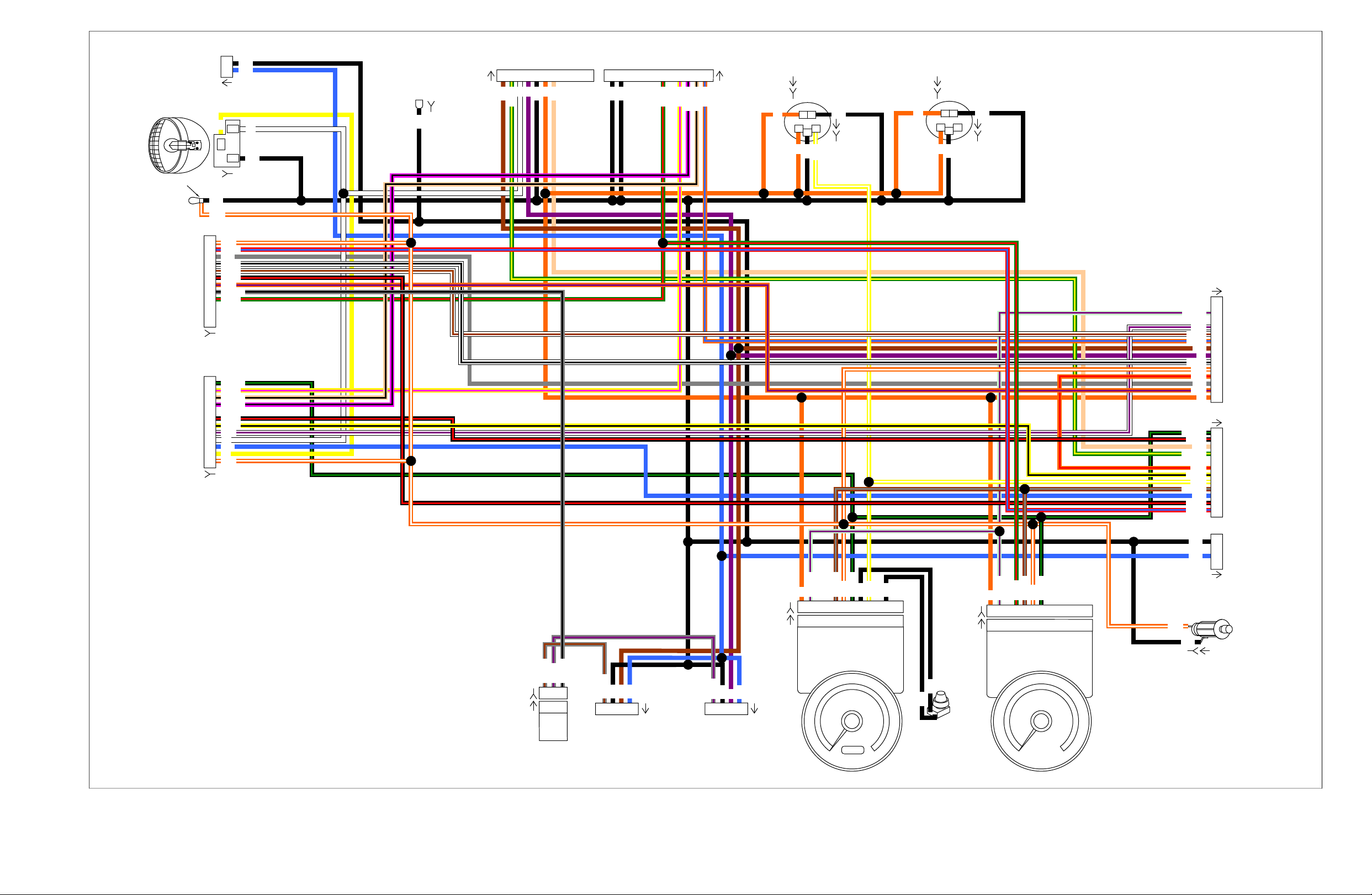
2
2
1
1
1
2
3
4
5
6
7
8
9
1
L1 L2 B
L1 L2 B
4 3 2 1 4 3 2 1
1 52 7 11
1 2 4 5 6 7
D
1
2
3
4
5
6
7
9
10
11
12
1
2
3
4
5
6
7
9
8
10
11
13
1
1 2
2
3
1
1 2
11271 62 53 4 211 36 4
2
3
B
1 2 4 5 6 7
86 9
1 52 7 1186 9
2
3
4
5
6
7
9
10
11
12
3
BK
BK
BK
BK
BK
BK
BK
BK
BK
BK
BK
BK
BK
BK
BK
BK
BE
BE
GY
BN
TN
BK
BK
BN
BN
TN
GY
BE
BE
BE
BE
O/W
O/W
O/W
O/W
O/W
O/R
O/W
Y/W
O/R
W/V
O/V
Y/W
O/W
Y/W
O/V
W/V
Y
Y
V
V
O
O
O
O
O
BK
O
O
O
V
W
W
W
GY/BK
GN/BK
GY/BK
GY/BN
GY/BN
BN/GY
BN/GY
BN/GY
GN/BK
BK/GN
BK/GN
BK/GN
LGN/V
LGN/V
LGN/V
TN/BK
TN/BK
PK/BK
PK/BK
R/BE
Y/PK
Y/PK
GY/V
GY/V
Y/BK
GN/R
BK/R
BK/R
Y/BK
O/BE
O/BE
W/BN
W/BK
R/BE
BK/R
BK/R
GN/R
GN/R
GN/Y
W/BK
W/BN
Fuel
[111A]
[111B]
[110A]
[110B]
[116A]
[116B]
[117A]
[117B]
[22B]
[24B]
[70A]
[21A]
[32A]
[15A]
[1A]
[2A]
Cigar
Lighter
To
Main
Harness
Speedometer
Tachometer
[39B]
[39A]
[108B]
[108A]
RH Front
Turn Signal
LH Front
Turn Signal
Odometer
Reset
Switch
(BK)
(GY)
(BK)
[31LA]
[31RA]
Rpm x 100
Voltmeter
[21B]
To Indicator
Lamps
[70B]
To Siren Amplifier
Harness
Front Fender
Tip Lamp
[32B]
(BK)
To
Right Hand
Controls
[22A]
(BK)
To
Left Hand
Controls
[24A]
(GY)
[154A]
[15B]
(BK)
To
Main
Harness
[2B]
(GY)
To
Main
Harness
[1B]
(BK)
[132B] [132A]
Pursuit
Flasher
Headlamp
Hi_Beam
Lo_Beam
GND
[38A]
[38B]
[69B]
[69A]
Ground
To Upper
Triple Clamp
GND 3
HDI Only
[29B]
et00088
Figure A-7. 2008 FLHTP, DOMESTIC and INTERNATIONAL Models, Interconnect Harness
Page 92

Figure A-7.Figure A-7.
2008 FLHTP, DOMESTIC and INTERNATIONAL Models,
Interconnect Harness
2008 FLHTP, DOMESTIC and INTERNATIONAL Models,
Interconnect Harness
Page 93

[32B]
Fender Tip Lamp
(DOM Only)
Right Rear
Directional
Lamp
Left Rear
Direction
Lamp
TailLamp
Fender Tip Lamp
(DOM Only)
From
Fairing
Harness
Right
Directional
and DOM
Running Lamp
Left
Directional
and DOM
Running Lamp
From
Fairing
Harness
From Main
Harness
Rear Lighting
[31RB]
License
PlateLamp
(HDI Only)
[7B]
Brake Light
Running Light (DOM )
Running Light (HDI)
[19B]
[19A]
[93B]
[94B]
[94A]
[93A]
[18A]
[45A]
[18B]
[45B]
[143B]
[143A]
68772-06
4 3 2 1
12
1 2 3 4 5 6 7 8
12
3456
1
2
3
4
2
1
1
2
3
4
3
2
1
123456
2
1
1
2
1
2
1
2
3
1
2
1
2
Right
Pursuit
Lamp (Blue)
FLHTP
Left
Pursuit
Lamp (Red)
FLHTP
[31LB]
From
Fairing
Harness
4 3 2 1
[73RB]
[73LB]
BK
BK
BK
BK
BK
BK
BK
BN
BE
BK
BK
BE
BN
BKBKBE
BE
BN
BK
BK
BE
BK
O/W
O/W
R/Y
R/Y
V/BN
BK
V/BN
BK
BK
BK
V/BN
BK
V/BN
O/W
BK
O/W
BK
O/W
BK
O/W
V
BKBNBE
O/W
R/Y
V
V
V
GY/BK
GY/BK
GY/BK
GY/BK
BE/W
BK
O/W
R/Y
BE/W
[31RA]
[31LA]
[32A]
[7A]
et00071
Figure A-8. 2008 FLHTP, DOMESTIC and INTERNATIONAL Models, Pursuit Lamps, Directional Lamps,Tail Lamp and Fender Tip Lamps
Page 94

Figure A-8.Figure A-8.
2008 FLHTP, DOMESTIC and INTERNATIONAL Models, Pursuit
Lamps, Directional Lamps,Tail Lamp and Fender Tip Lamps
2008 FLHTP, DOMESTIC and INTERNATIONAL Models, Pursuit
Lamps, Directional Lamps,Tail Lamp and Fender Tip Lamps
Page 95
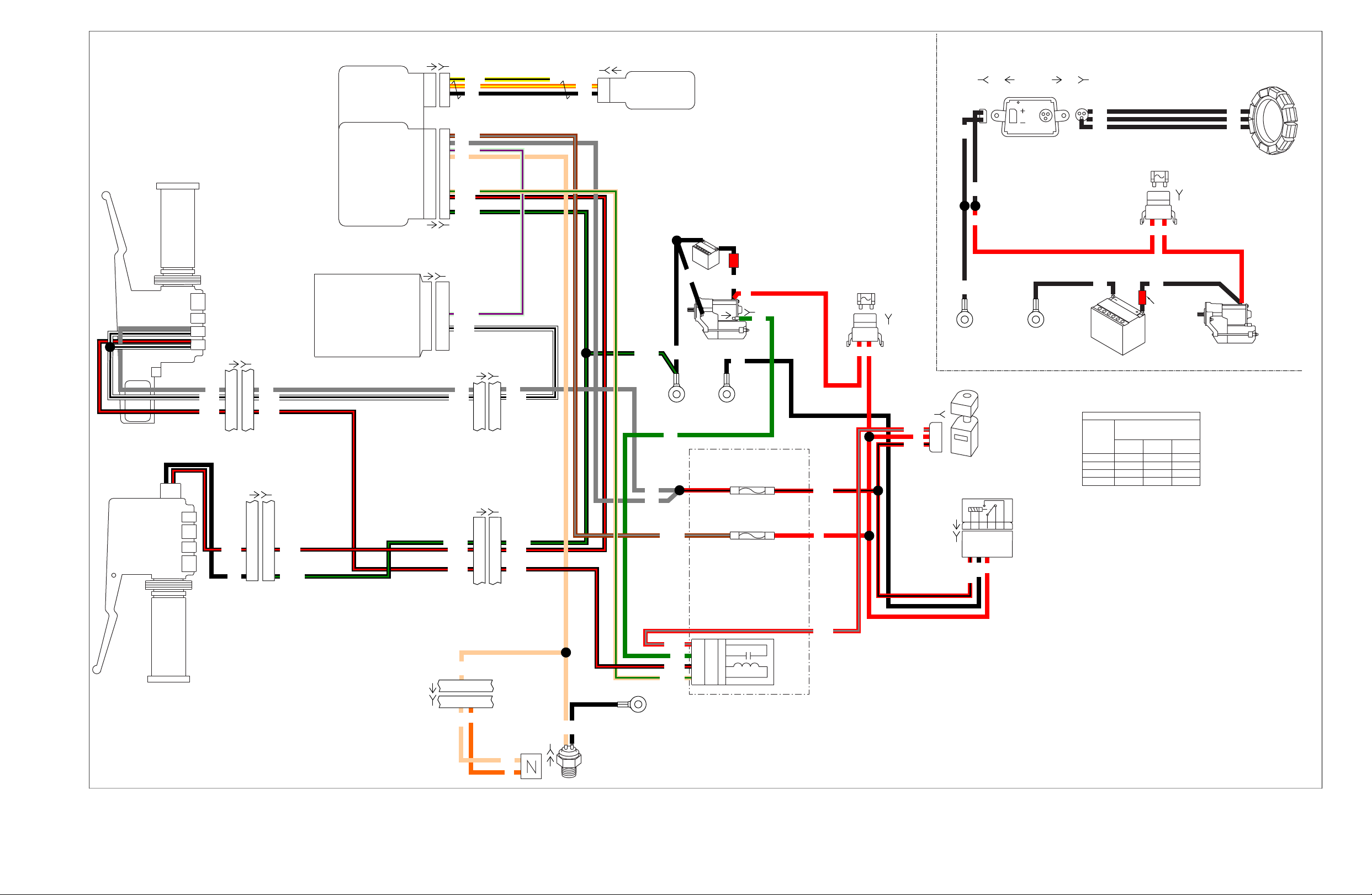
[128B]
[128A]
[2B]
[33B]
[1B]
Starter
Battery
2
11
12
3
6
1
2
3
1
2
3
4
9
10
12
1
2
3
4
9
10
12
[30A]
[78A] [78B]
[208A] [208B]
[209B] [209A]
[30B]
TSM/TSSM/HFSM
Battery
Ignition
Serial Data
Left
GND 1
Right
GND 2
40 A
MAXIFUSE
BA
[1A]
[2A]
(Black)
(Gray)
[24A]
(Gray)
[24B]
Ignition
Switch
Lighting
Relay
IGNITION SWITCH LEGEND
SWITCH
POSITION
"X" INDICATES CONTINUITY
BETWEEN LEAD WIRES
IN POSITION INDICATED
RED
RED/
GRAY
RED/
BLACK
LOCK X
OFF X
IGN X X X
ACC X X
Red
Band
[64B]
1F 1E
2C2D
Ignition - 15A
Battery - 15A
3
6
2
11
12
12
7
Clutch
Lockout
Switch
Left Hand
Controls
12
7
[22A]
(Black)
[22B]
6
4
3
6
4
3
Engine Off/Run Switch
Starter Switch
Right Hand
Controls
ECM
Serial Data 697269
72
12V Run/Stop Switch Power
Starting System
[126B]
[126A]
86(1)
85(2)
30(3)
87A(4)
87(5)
2G
3H
4G
4H
3G
3
5
1
2
Start
Relay
30
87
86
85
[5B]
Neutral Switch
1
2
3
4
1
2
1
2
3
4
HFSM
Receive Antenna
Xmit Antenna A
Xmit Antenna B
Xmit Antenna A
Xmit Antenna B
Unused
Start Relay Control
Clutch Switch
Ground
[21B]
(BK)
LH GND
Stud
(Dirty)
GND 1A
[131]
Neutral
Neutral
Switch
5
5 6
[21A]
Powertrain
Grounds
40 A
MAXIFUSE
[77B]
Starter
Battery
B A
Charging System
Left Dirty
GND
[77A]
Stator
DC AC
[46A] [46B]
Red
Band
2
1
[5B]
Turn Signal/
Turn Signal
Security
Module
Hands Free
Security
Module
B A
GY
TN
BK
BN/GY
TN/GN
BK/GN
LGN/V
LGN/V
BK/R
W/BK
GY GY
BK/R BK/R
W/BK W/BK
BK
TN
GN
BK
BK
BK
BK
BK
BK BK
BK
BK
BK
BK
BK
BK
BK
BK
GY
BK
TN
TN
TN
BK/GN
BK/GN
BK/GN
BK/GN
TN/GN
GY
GN
GY
BK
GN
BN/GY
BK/R
BK/R
BK/R BK/R
BK/R
R/GY
R/GY
R/BK
R/BK
R/GY
BK/R
W/BK
GY
W/BK
BK/R
O
O
R
R
R/BK
R
R
R
R
R
R
R
[33A]
Y/BK
O/Y
BK
O/Y
et00070
Figure A-9. 2008 FLHTP, DOMESTIC and INTERNATIONAL Models, Starting and Charging
Page 96

Figure A-9.Figure A-9.
2008 FLHTP, DOMESTIC and INTERNATIONAL Models, Starting
and Charging
2008 FLHTP, DOMESTIC and INTERNATIONAL Models, Starting
and Charging
Page 97
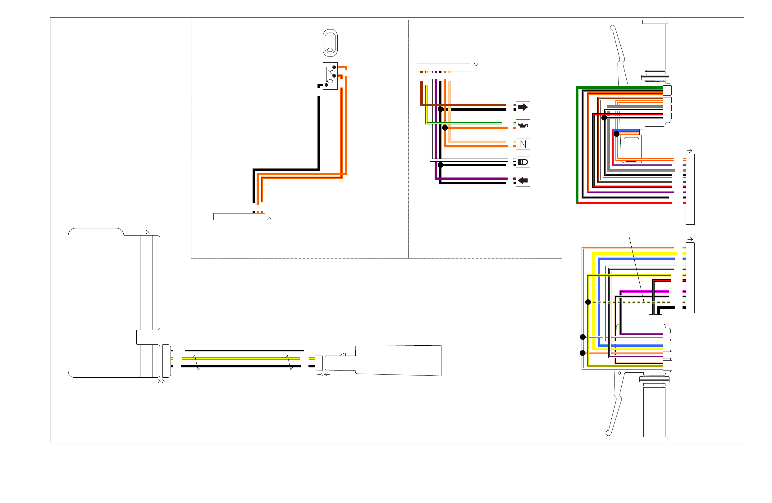
FLHTP
Only
To Fairing
Harness
To Fairing
Harness
[22B]
(BK)
[24B]
(GY)
[22A]
[24A]
ACC
[105A]
[105B]
To Fairing
Harness
1
23
1
2
3
4
5
6
7
8
9
Right
Hand
Controls
1
2
3
4
5
6
7
8
9
10
11
12
10
11
12
Clutch Lockout Switch
Siren Off/Run Switch
Headlamp Hi/Lo Switch
Left Directional Switch
Left
Hand
Controls
Horn/Siren Switch
Move Y/BK wire to terminal
11 when using Whelen Siren
Amplifier & 'Air Horn'
function
Off/Aux Pursuit Switch
Right Directional Switch
Engine Off/ Run Switch
Starter Switch
Stoplamp Switch
Right
Turn
Oil
Pressure
Neutral
High
Beam
Left
Turn
[21B]
Indicator
Lamps
(BK)
1 2 3 4 5 6 7 8 9 10
From Fairing
Harness
[21A]
212
1
Antenna ’A’
Antenna ’B’
Hands Free Antenna
[209B] [209A]
[30A]
2
1
3
2
1
3
Receive Antenna
Transmit Antenna A
Transmit Antenna B
2
1
3
5
4
6
8
7
9
11
10
12
Battery
Ignition
Serial Data
Neutral Switch
Left Turn Feed
Right Turn Feed
Right Turn Switch Input
Left Turn Switch Input
Start Relay Control
Clutch Switch
Alarm Signal
Ground
[208A] [208B]
Hands Free Security
Module (HFSM)
For Turn Signal & Security
Module (TSM/TSSM)
BK
O/Y
BK
O/Y
Y/BK
BK
BK
O/R
O
O/R
O
BN
BN
BK
TN
BK
BK
BK
TN
O
O
W
Y
W
W
V
O
V
GN/Y
GN/Y
GY
BE
BK
O/W
O/W
W/V
O/V
GY/BK
PK/BK
TN/BK
R/BE
W/BK
W/BN
GN/R
BK/R
BK/R
Y/BK
Y/BK
et00089
Figure A-10. 2008 FLHTP, DOMESTIC and INTERNATIONAL Models, Handlebar Switches, Indicator Lamps, Fairing Cap Switches and HFSM Antenna
Page 98

Figure A-10.Figure A-10.
2008 FLHTP, DOMESTIC and INTERNATIONAL Models,
Handlebar Switches, Indicator Lamps, F airing Cap Switches and
HFSM Antenna
2008 FLHTP, DOMESTIC and INTERNATIONAL Models,
Handlebar Switches, Indicator Lamps, F airing Cap Switches and
HFSM Antenna
Page 99
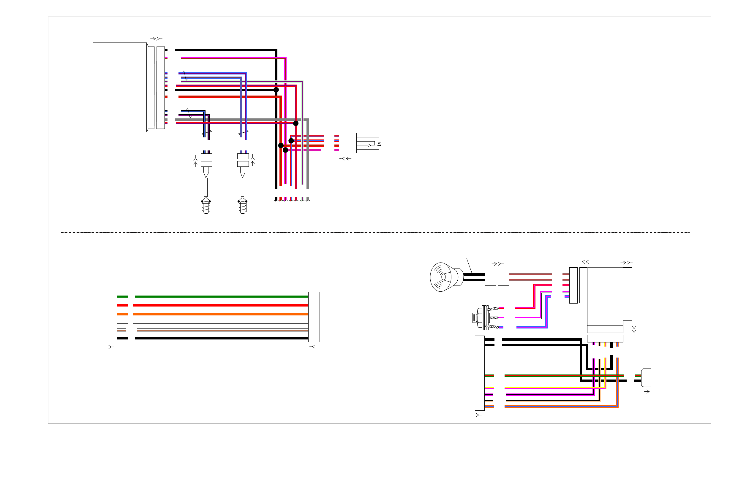
GN
BK
GY
BK
GY
BK
R/V
BK
BK
BK
BK
BK
R/V
R/V
W
O
R
PK/BK
PK/BK
TN/BK
BE/PK
BE/PK
BK/BE
BK/BE
PK/BN
PK/BN
PK/BN
BE/BN
LGN/V
TN/BK
GY/R
GY/R
R/PK
Y/PK
O/BE
W/PK
R/PK
W/PK
GN/R GN/R
W/BN
BK/V
BK/V
BE/BN
BE/V
R/BN
R/BE
LGN/V
R/BN
BE/V
R/BE
R/BE
R/BN
Y/PK
O/BE
1B
2A
2B
2C
2E
3B
3C
3A
2D
1E
3F
3C
3A
2D
1E
3F
3E
2F 1F 1D 1A 1C
2F 1F 1D 1A 1C
12
11
6
4
3
2
1
1
2
3
4
5
6
4
3
2
1
4
3
2
1
1
2
3
4
5
6
1
2
1
2
1
2
Ref: Siren wires
are not polarity
sensitive
Siren/PA
Speaker
FLHTP-FRG
Siren Amplifier Harness
To
interconnect
harness
Microphone
Jack
[68]
[57A]
[229B]
[230B]
[72A]
[72A]
[72B] [72B]
[72B]
[59B]
[57B]
[70B]
To optional
pole lamp
Siren
Amplifier
To optional
dealer installed
strobe power
supply
To optional
dealer installed
strobe lights
FLHTP-FRG Strobe Harness
A B
A B
A B
A B
ABS
Control
Module
[166A]
[166B]
[167B]
[167A]
[168B]
[201B] [201A]
[168A]
To main harness
page 1
Rear Wheel
Speed Sensor
Front Wheel
Speed Sensor
ABS
Diode
Pack
1
3
7
8
9
10
11
13
17
18
19
20
1
3
7
8
9
10
11
13
17
18
19
20
ECU/Solenoid ground
ECU/Solenoid power
Rear brake input
Rear wheel speed (-)
Rear wheel speed (+)
Front wheel speed (+)
Front wheel speed (-)
Serial data
Motor ground
Front brake input
Ignition wake-up
Motor power
[70A]
et00013
Figure A-11. 2008 FLHTP, DOMESTIC and INTERNATIONAL Models, Anti-Lock Brake System (ABS) Siren Amplifier and Strobe Harness
Page 100

Figure A-11.Figure A-11.
2008 FLHTP, DOMESTIC and INTERNA TIONAL Models, Anti-Lock
Brake System (ABS) Siren Amplifier and Strobe Harness
2008 FLHTP, DOMESTIC and INTERNA TIONAL Models, Anti-Lock
Brake System (ABS) Siren Amplifier and Strobe Harness
 Loading...