

Page 1

2008 FLHTCUSE3 Model Service Manual Supplement
99500-08
©2007 H-D.
Page 2

Harley-Davidson motorcycles conform to all applicable U.S.A. Federal Motor Vehicle Safety Standards
and U.S.A. Environmental Protection Agency regulations effective on the date of manufacture.
To maintain the safety, dependability, and emission and noise control performance, it is essential that
the procedures, specifications and service instructions in this manual are followed.
Any substitution, alteration or adjustment of emission system and noise control components outside of
factory specifications may be prohibited by law.
IMPORTANT NOTICE
Harley-Davidson Motor Company
Page 3

2008 FLHTCUSE3 Model
Service Manual Supplement
©2007 H-D.
ALL RIGHTS RESERVED
99500-08
Printed in the U.S.A.
VISIT THE HARLEY-DAVIDSON WEB SITE
http://www.harley-davidson.com
Page 4

Blank Text Here
Page 5

Blank Text Here
READER COMMENTS
Please comment on the completeness, accuracy, organization, usability, and readability of this manual.
Please list the page, item, and part number(s) of any errors you find in this manual.
Please tell us how we can improve this manual.
Occupation:
Name: Dealership:
Street: Department:
City: State: Zip:
Please clip out and mail to:
Service Communications Department
Harley-Davidson Motor Company
P.O. Box 653
Milwaukee, WI USA 53201
The Harley-Davidson Service Communications Department maintains a continuous effort to improve the quality
and usefulness of its publications. To do this effectively, we need user feedback - your critical evaluation of
this manual.
2008 FLHTCUSE3 Model Service Manual Supplement (99500-08)
Page 6

NOTES
Page 7
ABOUT THIS MANUAL
GENERAL
This Service Manual Supplement has been designed to be
used with the current Service Manual and has been prepared
with two purposes in mind. First, it will acquaint the user with
the construction of the Harley-Davidson product and assist in
the performance of basic maintenance and repair. Secondly,
it will introduce to the professional Harley-Davidson Technician
the latest field-tested and factory-approved major repair
methods.We sincerely believe that this Service Manual Supplement will make your association with Harley-Davidson
products more pleasant and profitable.
NOTE
This Service Manual Supplement provides information unique
to this model motorcycle. Any information not presented in this
supplement can be found in the appropriate Service Manual
or Electrical Diagnostic Manual.
HOW TO USE YOUR SERVICE MANUAL
SUPPLEMENT
Use the TABLE OF CONTENTS (which follows this FOREWORD) and the INDEX (at the back of this manual) to quickly
locate subjects. Sections and topics in this manual are
sequentially numbered for easy navigation.
CHAPTERNO.
Maintenance1
Chassis2
Engine3
Fuel System4
Electric Starter5
Drive6
Transmission7
Electrical8
Appendix A WiringA
Appendix B GlossaryB
For example, a cross-reference shown as 2.1 SPECIFICA-
TIONS refers to chapter 2 CHASSIS, heading 2.1 SPECIFICATIONS.
If the subject you seek is not in this supplement, refer to the
corresponding section in the appropriate Service Manual.
Check the title page located in the front of each section to find
the subject.
For quick and easy reference, all pages contain a section
number followed by a page number. For example, page 3-5
refers to page 5 in section 3.
In figure legends, the number following the name of a part
indicates the quantity necessary for one complete assembly.
PREPARATION FOR SERVICE
Stop the engine when refueling or servicing the fuel
system. Do not smoke or allow open flame or sparks near
gasoline. Gasoline is extremely flammable and highly
explosive, which could result in death or serious injury.
(00002a)
Good preparation is very important for efficient service work.
A clean work area at the start of each job will allow you to
perform the repair as easily and quickly as possible, and will
reduce the incidence of misplaced tools and parts. A motorcycle
that is excessively dirty should be cleaned before work starts.
Cleaning will occasionally uncover sources of trouble. Tools,
instruments and any parts needed for the job should be
gathered before work is started. Interrupting a job to locate
tools or parts is a distraction and causes needless delay.
NOTES
• To avoid unnecessary disassembly, carefully read all relative service information before repair work is started.
• In figure legends, the number which follows the name of
a part indicates the quantity necessary for one complete
assembly.
• When servicing a vehicle equipped with the HarleyDavidson Smart Security System (H-DSSS), you must
first disarm the security system. Either keep the fob in
close proximity to the vehicle, or use Digital Technician to
disable the security system while the vehicle is being serviced and re-enable the system after service is completed.
SERVICE BULLETINS
In addition to the information presented in this Service Manual
Supplement and the appropriate Service Manual, HarleyDavidson Motor Company will periodically issue Service Bulletins to Harley-Davidson dealers. Service Bulletins cover
interim engineering changes and supplementary information.
Consult the Service Bulletins to keep your product knowledge
current and complete.
USE GENUINE REPLACEMENT PARTS
Do not use aftermarket parts and custom made front forks
which can adversely affect performance and handling.
Removing or altering factory installed parts can adversely
affect performance and could result in death or serious
injury. (00001a)
To ensure satisfactory and lasting repairs, carefully follow the
Service Manual instructions and use only genuine HarleyDavidson replacement parts. Behind the emblem bearing the
words GENUINE HARLEY-DAVIDSON stand more than 100
years of design, research, manufacturing, testing and inspecting
experience.This is your assurance that the parts you are using
will fit right, operate properly and last longer.
FOREWORD
WARNINGS AND CAUTIONS
Statements in this service manual preceded by the following
words are of special significance.
I
Page 8

WARNING indicates a potentially hazardous situation
which, if not avoided, could result in death or serious
injury. (00119a)
CAUTION indicates a potentially hazardous situation
which, if not avoided, may result in minor or moderate
injury. (00139a)
CAUTION used without the safety alert symbol indicates
a potentially hazardous situation which, if not avoided,
may result in property damage. (00140a)
NOTE
Refers to important information, and is placed in italic type. It
is recommended that you take special notice of these items.
Proper service and repair is important for the safe, reliable
operation of all mechanical products.The service procedures
recommended and described in this service manual are
effective methods for performing service operations.
When reference is made in this manual to a specific brand
name product, tool or instrument, an equivalent product, tool
or instrument may be substituted.
Kent-Moore Products
All tools mentioned in this manual with an "HD", "J" or "B"
preface must be ordered through SPX K ent-Moore. For ordering
information or product returns, warranty or otherwise, visit
www.spx.com.
Loctite Sealing and Threadlocking Pr oducts
Some procedures in this manual call for the use of Loctite
products. If you have any questions regarding Loctite product
usage or retailer/wholesaler locations, please contact Loctite
Corp. at www.loctite.com.
PRODUCT REGISTERED MARKS
Allen, Amp Multilock, Bluetooth, Brembo, Delphi, Deutsch,
Dunlop, Dynojet, Fluke, G.E. Versilube, Gunk, Hydroseal,
Hylomar, Kevlar, Lexan, Loctite, Lubriplate, Keps, K&N, Magnaflux, Marson Thread-Setter Tool Kit, MAXI fuse, Molex, MPZ,
Mulitilock, Novus, Packard, Pirelli, Permatex, Philips, PJ1,
Pozidriv , Robinair , S100, Sems, Snap-on, Teflon, Threadlocker ,
Torca, Torco, TORX, Tufoil, Tyco, Ultratorch, Velcro, X-Acto,
and XM Satellite Radio are among the trademarks of their
respective owners.
Always wear proper ey e protection when using hammer s,
arbor or hydraulic presses, gear pullers, spring compressors, slide hammers and similar tools. Flying parts
could result in death or serious injury. (00496b)
Some of these service operations require the use of tools
specially designed for the purpose.These special tools should
be used when and as recommended. It is important to note
that some warnings against the use of specific service methods,
which could damage the motorcycle or render it unsafe, are
stated in this service manual. Howe v er, please remember that
these warnings are not all-inclusive. Inadequate safety precautions could result in death or serious injury.
Since Harley-Davidson could not possibly know, evaluate or
advise the service trade of all possible ways in which service
might be performed, or of the possible hazardous consequences of each method, we have not undertaken any such
broad evaluation. Accordingly, anyone who uses a service
procedure or tool which is not recommended by HarleyDavidson must first thoroughly satisfy himself that neither his
nor the operator's safety will be jeopardized as a result. F ailure
to do so could result in death or serious injury.
PRODUCT REFERENCES
H-D MICHIGAN, INC.TRADEMARK
INFORMATION
Harley, Harley-Davidson, H-D, Bar & Shield, Digital Tech,
Digital Technician, Destroyer, Deuce, Dyna, Electra Glide,
Evolution, F at Boy, Glaze, Gloss, H-D, H-Dnet.com, HD , Harley,
Heritage Softail, Heritage Springer, Low Rider, Night Rod, Night
Train, Profile, Revolution, Road Glide, Road King, Rocker,
Softail, Sportster, Sun Ray, Sunwash, Tech Link, Twin Cam
88, Twin Cam 88B, Twin Cam 96, Twin Cam 96B, Twin Cam
103, Twin Cam 103B, Twin Cam 110, Twin Cam 110B, TourPak, Screamin' Eagle, Softail, Super Guide, Super Premium,
SYN3, Ultra Glide, V-Rod, VRSC, Wide Glide, and HarleyDavidson Genuine Motor Parts and Genuine Motor Accessories
are among the trademarks of H-D Michigan, Inc.
CONTENTS
All photographs, illustrations and procedures may not necessarily depict the most current model or component, but are
based on the latest production information available at the time
of publication.
Since product improvement is our continual goal, HarleyDavidson reserves the right to change specifications, equipment
or designs at any time without notice and without incurring
obligation.
Read and follow warnings and directions on all products.
Failure to follow warnings and directions can result in
death or serious injury. (00470b)
II FOREWORD
Page 9

MAINTENANCE
1.1 SCHEDULED MAINTENANCE
General...............................................................................1-1
1.2 HYDRAULIC CLUTCH FLUID
General...............................................................................1-2
Clutch Fluid Level...............................................................1-2
1.3 BLEEDING CLUTCH FLUID LINE
Draining and Filling.............................................................1-3
Bleed Clutch Master Cylinder.............................................1-4
Bleed Fluid Line and Actuator............................................1-4
Return Motorcycle to Service.............................................1-4
1.4 ENGINE LUBRICATION SYSTEM
General...............................................................................1-5
1.5 CRITICAL FASTENERS
Inspection...........................................................................1-6
CHASSIS
2.1 SPECIFICATIONS: CHASSIS
General...............................................................................2-1
2.2 VEHICLE IDENTIFICATION NUMBER
(V.I.N.)
Vehicle Identification Number (V.I.N.): FLHTCUSE3..........2-2
General........................................................................2-2
Location.......................................................................2-2
Abbreviated V.I.N.........................................................2-2
2.3 FOOTBOARDS AND CONTROLS
Rider Footboards................................................................2-3
Removal......................................................................2-3
Installation...................................................................2-4
Shift Levers.........................................................................2-5
Replace Pegs..............................................................2-5
Replace Heel-Toe Shift Levers....................................2-5
Rear Brake Pedal...............................................................2-6
Adjustable Passenger Footboards......................................2-6
Remove.......................................................................2-6
Disassemble................................................................2-6
Assemble.....................................................................2-7
Install...........................................................................2-8
Adjust..........................................................................2-8
2.4 HIGHWAY PEGS
Disassembly.......................................................................2-9
Removing Clamp................................................................2-9
Installing Clamp..................................................................2-9
Assembly..........................................................................2-10
2.5 FRONT AXLE COVERS
Replacement....................................................................2-11
Assembly..........................................................................2-14
Pull Wire Leads.........................................................2-14
Install Switch Housings.............................................2-15
Install Wire Lead Ter minals.......................................2-16
Installing Handlebars........................................................2-17
Clamp Handlebars to Risers.....................................2-17
Assemble Brake Controls..........................................2-17
Assemble Clutch Controls.........................................2-18
Returning to Service.........................................................2-19
2.8 HANDGRIPS
General.............................................................................2-20
Preparing Motorcycle.......................................................2-20
Separating Connectors.....................................................2-20
Replacing Handgrips........................................................2-20
Remove Left Handgrip..............................................2-20
Install Left Handgrip..................................................2-21
Remove Right Handgrip............................................2-22
Install Right Handgrip................................................2-22
Mating Connectors...........................................................2-23
Returning to Service.........................................................2-23
2.9 CLUTCH MASTER CYLINDER AND
RESERVOIR
General.............................................................................2-24
Removal...........................................................................2-24
Disassembly.....................................................................2-25
Assembly..........................................................................2-26
Installation........................................................................2-26
2.10 CLUTCH HAND LEVER
Removal...........................................................................2-28
Installation........................................................................2-28
2.11 CLUTCH FLUID LINE
Removal...........................................................................2-29
Installation........................................................................2-29
2.12 SEAT
General.............................................................................2-31
Removal...........................................................................2-31
Cleaning and Inspection...................................................2-32
Installation........................................................................2-32
2.13 RIDER BACKREST
General.............................................................................2-33
Removal...........................................................................2-33
Installation........................................................................2-33
Adjusting Tilt Angle...........................................................2-33
Adjusting Front to Rear.....................................................2-33
2.14 TOUR-PAK
Removal...........................................................................2-35
Installation........................................................................2-36
2.15 SADDLEBAGS
Removal...........................................................................2-38
Installation........................................................................2-38
TABLE OF CONTENTS
2.6 LOWER TRIPLE CLAMP COVER
Replacement....................................................................2-12
2.7 HANDLEBARS
Removal...........................................................................2-13
Disassembly.....................................................................2-14
2.16 SADDLEBAGS LATCH
Removal...........................................................................2-39
Installation........................................................................2-39
2.17 SADDLEBAG SUPPORTS
Removal...........................................................................2-40
III
Page 10
TABLE OF CONTENTS
Installation........................................................................2-40
2.18 MUFFLER END CAP
Replacement....................................................................2-42
ENGINE
3.1 SPECIFICATIONS: ENGINE
General...............................................................................3-1
Manufacturing Tolerances...................................................3-1
3.2 SERVICE WEAR LIMITS
General...............................................................................3-3
3.3 CYLINDER HEAD
General...............................................................................3-5
Removal.............................................................................3-5
Determining Service...........................................................3-5
Disassembly.......................................................................3-5
Cleaning.............................................................................3-6
Inspection...........................................................................3-8
Cylinder Head..............................................................3-8
Valve Guides...............................................................3-8
Valves..........................................................................3-8
Valve Springs..............................................................3-8
Tapered Keepers.........................................................3-8
Valve Seats.................................................................3-8
Replacing Valve Guides......................................................3-9
Removal......................................................................3-9
Installation.................................................................3-10
Assembly..........................................................................3-13
Installation........................................................................3-15
3.4 PISTONS
General.............................................................................3-16
Measuring Piston..............................................................3-16
3.5 BORING AND HONING CYLINDERS
Inspection.........................................................................3-17
Cylinder Bore Finished Size.............................................3-18
Piston Orientation.............................................................3-19
FUEL SYSTEM
4.1 AIR CLEANER COVER
General...............................................................................4-1
Removal.............................................................................4-1
Installation..........................................................................4-1
ELECTRIC STARTER
5.1 SPECIFICATIONS: STARTER
General...............................................................................5-1
DRIVE
6.1 SPECIFICATIONS: DRIVE
General...............................................................................6-1
6.2 CLUTCH RELEASE BEARING AND
PUSHROD
Removal.............................................................................6-2
Installation..........................................................................6-2
Measure Release Plate Movement.............................6-2
Install Clutch Inspection Cover....................................6-2
TRANSMISSION
7.1 SPECIFICATIONS:TRANSMISSION
General...............................................................................7-1
7.2 CLUTCH RELEASE COVER
Removal.............................................................................7-2
Installation..........................................................................7-2
Fill and Bleed......................................................................7-3
7.3 SECONDARY CLUTCH ACTUATOR
Replacement......................................................................7-4
ELECTRICAL
3.6 CRANKCASE ASSEMBLY
General.............................................................................3-20
Assembly..........................................................................3-20
3.7 OIL COOLER
Operation..........................................................................3-23
Removal...........................................................................3-23
Installation........................................................................3-23
3.8 OIL COOLER ADAPTER
Removal...........................................................................3-25
Disassembly.....................................................................3-25
Assembly..........................................................................3-25
Installation........................................................................3-25
IV TABLE OF CONTENTS
8.1 ELECTRICAL PROTECTION
Fuses and Relays...............................................................8-1
8.2 BULB CHART
General...............................................................................8-3
8.3 HEADLAMP
General...............................................................................8-4
Removal.............................................................................8-4
Installation..........................................................................8-5
8.4 AUXILIARY LAMPS AND BRACKETS
Removing Lamps................................................................8-7
Removing Lamp Bracket....................................................8-8
Installing Lamp Bracket......................................................8-8
Installing Lamps.................................................................8-8
Mount Lamp................................................................8-8
Final Assembly............................................................8-8
Page 11

TABLE OF CONTENTS
Align Lamps................................................................8-9
Replacing Bulb.................................................................8-10
8.5 FRONT TURN SIGNALS
Removal...........................................................................8-12
Installation........................................................................8-12
8.6 HEATED SEAT
General.............................................................................8-14
Controls.....................................................................8-14
Warm-Up...................................................................8-14
Diagnostics.......................................................................8-14
Diagnostic Tips..........................................................8-14
Diagnostic Notes.......................................................8-14
8.7 HEATED HANDGRIPS
General.............................................................................8-17
Diagnostics.......................................................................8-17
Diagnostic Tips..........................................................8-17
Diagnostic Notes.......................................................8-17
8.8 FAIRING CAP AND SWITCHES
Removal...........................................................................8-21
Installation........................................................................8-21
8.9 PASSENGER HEADSET RECEPTACLE
Repair...............................................................................8-23
Replace Weather Cap...............................................8-23
8.14 ADVANCED AUDIO AMPLIFIER
General.............................................................................8-33
Removal...........................................................................8-33
Installation........................................................................8-33
8.15 GARAGE DOOR OPENER
Transmitter........................................................................8-35
Removal....................................................................8-35
Installation.................................................................8-35
Receiver...........................................................................8-35
Installation.................................................................8-35
Remote Control Garage Door Opener..............................8-36
FCC Notices..............................................................8-36
Program the Receiver and Transmitter......................8-36
8.16 AUT OMA TIC COMPRESSION RELEASE
General.............................................................................8-37
Removal...........................................................................8-37
Installation........................................................................8-37
Compression Test.............................................................8-38
Diagnostics.......................................................................8-39
Diagnostic Tips..........................................................8-39
Diagnostic Notes.......................................................8-39
8.17 TWIST GRIP SENSOR (TGS)
Removal...........................................................................8-42
Installation........................................................................8-42
Reset TGS/ECM........................................................8-43
8.10 XM SATELLITE RADIO
General.............................................................................8-24
XM Antenna......................................................................8-24
Remove.....................................................................8-24
Installation.................................................................8-24
XM Module.......................................................................8-25
Removal....................................................................8-25
Installation.................................................................8-25
Activation..........................................................................8-25
8.11 GPS NAVIGATION
General.............................................................................8-27
GPS Antenna...................................................................8-27
Removal....................................................................8-27
Installation.................................................................8-27
GPS Navigation Module...................................................8-28
Removal....................................................................8-28
Installation.................................................................8-28
8.12 RADIO SOFTWARE UPDATE
General.............................................................................8-29
Opening Diag Test Display...............................................8-29
Identifying Version Number...............................................8-29
Updating Receiver Software.............................................8-29
Confirming Version Number.............................................8-30
8.13 ADVANCED AUDIO RADIO
Removing Advanced Audio..............................................8-31
Installing Advanced Audio................................................8-31
8.18 POWER LOCKS
General.............................................................................8-44
Power Lock Lockset:Tour-Pak..........................................8-44
Removal....................................................................8-44
Installation.................................................................8-44
Actuator: Tour-Pak............................................................8-44
Removal....................................................................8-44
Assembly...................................................................8-45
Power Locks: Saddlebags................................................8-45
Removal....................................................................8-45
Installation.................................................................8-45
Actuator: Saddlebag.........................................................8-46
Disassembly..............................................................8-46
Assembly...................................................................8-47
Power Lock Module..........................................................8-48
Removal....................................................................8-48
Installation.................................................................8-48
Power Lock Fob................................................................8-48
General......................................................................8-48
Entering Program Mode............................................8-48
Program Mode...........................................................8-48
Replacing the Battery................................................8-49
Diagnostics.......................................................................8-49
Diagnostic Tips..........................................................8-49
Diagnostic Notes.......................................................8-49
8.19 HARLEY-DA VIDSON SMART SECURITY
SYSTEM
General.............................................................................8-52
HFSM...............................................................................8-52
Removal....................................................................8-52
Installation.................................................................8-52
TABLE OF CONTENTS V
Page 12

TABLE OF CONTENTS
Antenna............................................................................8-52
Remove.....................................................................8-52
Install.........................................................................8-52
Smart Siren......................................................................8-53
Remove.....................................................................8-53
Install.........................................................................8-53
Replace Battery.........................................................8-53
Troubleshooting................................................................8-54
APPENDIX A WIRING
A.1 CONNECTORS
Connectors.........................................................................A-1
Function and Location................................................A-1
Place and Color..........................................................A-1
Connector Number......................................................A-1
Repair Instructions......................................................A-1
A.2 WIRING DIAGRAMS
Wiring Diagram Information...............................................A-2
Wire Color Codes........................................................A-2
Wiring Diagram Symbols............................................A-2
Wiring Diagrams.................................................................A-3
APPENDIX B GLOSSARY
B.1 GLOSSARY
Acronyms and Abbreviations..............................................B-1
REFERENCE MATERIAL
TOOLS...........................................................I
TORQUE VALUES.......................................III
INDEX.........................................................VII
VI TABLE OF CONTENTS
Page 13

SUBJECT............................................................................................................................PAGE NO.
1.1 SCHEDULED MAINTENANCE.................................................................................................1-1
1.2 HYDRAULIC CLUTCH FLUID...................................................................................................1-2
1.3 BLEEDING CLUTCH FLUID LINE............................................................................................1-3
1.4 ENGINE LUBRICATION SYSTEM............................................................................................1-5
1.5 CRITICAL FASTENERS............................................................................................................1-6
MAINTENANCE
Page 14

NOTES
Page 15

1.1SCHEDULED MAINTENANCE
GENERAL
The scheduled maintenance table in this section lists the
maintenance requirements for the FLHTCUSE3. Refer to
Table 1-1. Scheduled Maintenance Intervals
1000 MI.
1600 KM
Tires
ators
switches
Air suspension
applicable)
bags
stablizers
Battery
Exhaust system
Road test
NOTES:
PROCEDUREITEM SERVICED
tread
and leakage
connections
loose or missing fasteners or
heat shields
system functions
1. Should be performed by an authorized Harley-Da vidson dealer , unless you hav e the proper tools, service data and are mechanically
qualified.
2. Disassemble, lubricate and inspect every 50,000 miles (80,000 kilometers).
3. Perform annually.
4. Change D.O.T. 4 and flush brake system every two years.
5. Perform at each rear tire change.
Table 1-1. In addition to this supplement, see the Touring
Models Service Manual for service procedures.
5000 MI.
8000 KM
10,000 MI.
16,000 KM
15,000 MI.
24,000 KM
20,000 MI.
32,000 KM
XXXReplacePrimary chaincase lubricant
XXReplaceTransmission lubricant
XReplace
40,000 KM
XXXXXXReplaceEngine oil and filter
XXXXXXInspect, service as requiredAir cleaner
XXXXXXCheck pressure, inspect
XXXXXXInspect for wearBrake pads and discs
XXXXXInspectSpark plugs
XXXXXXCheck operationElectrical equipment and
XXXXXXLubricate hinges and latchesFuel door, Tour-Pak, saddle-
XXXXXXVerify component and
NOTES25,000 MI.
1XXXXXXInspect for leaksOil lines and brake system
4ReplaceClutch fluid
1XXXXXXInspect, adjust beltRear belt and sprockets
5Inspect for wearRear wheel sprocket isol-
1XXXXXXCheck, adjust and lubricateBrake and clutch controls
1XXXXXXInspect and lubricateJiffy stand
1XXXXXXInspect for leaksFuel lines and fittings
1XReplaceFuel tank filter
4XXXXXXCheck levels and conditionBrake fluid
1, 2ReplaceFront fork oil
2XXXLubricateSteering head bearings
1XAdjust
1XXXXXXCheck pressure, operation
1XXInspectWindshield bushings (if
1XXXCheck tightnessCritical fasteners
1XXInspectEngine mounts and
3Check battery and clean
3XXXXXXInspect for leaks, crac ks, and
2008 FLHTCUSE3 Service: Maintenance 1-1
Page 16
GENERAL
sm01748
1.2HYDRAULIC CLUTCH FLUID
The clutch is hydraulically actuated.The hand lever actuated
master cylinder creates pressure in the clutch fluid line that
activates a secondary clutch actuator mounted in the clutch
release cover. The secondary clutch actuator piston extends
and contacts a pushrod to disengage the clutch.
D.O.T. 4 hydraulic brake fluid is used in the hydraulic
clutch. Do not use other types of fluids as they are not
compatible and could cause equipment damage. (00353a)
D.O.T. 4 brake fluid will damage painted and body panel
surfaces it comes in contact with. Alwa ys use caution and
protect surfaces from spills whenever brake work is performed. F ailure to comply can result in cosmetic damage.
(00239b)
• Do not wipe any spilled brake fluid off of finished surf aces.
Always flush the affected components with water (not
soapy).
Direct contact of D.O.T. 4 brake fluid with eyes can cause
irritation. Avoid eye contact. In case of eye contact flush
with large amounts of water and get medical attention.
Swallowing large amounts of D.O .T . 4 brake fluid can cause
digestive discomfort. If swallowed, obtain medical attention. Use in well ventilated area. KEEP OUT OF REACH OF
CHILDREN. (00240a)
Do not allow dirt or debris to enter the master cylinder
reservoir . Dirt or debris in the reservoir can cause improper
operation and equipment damage. (00205c)
1. Stand motorcycle upright.Turn handlebars to level reservoir.
2. Remove two screws , clutch master cylinder/reservoir cover
and cover gasket.
NOTE
Clutch fluid volume in reservoir actually increases with clutch
wear. Do NOT overfill reservoir.
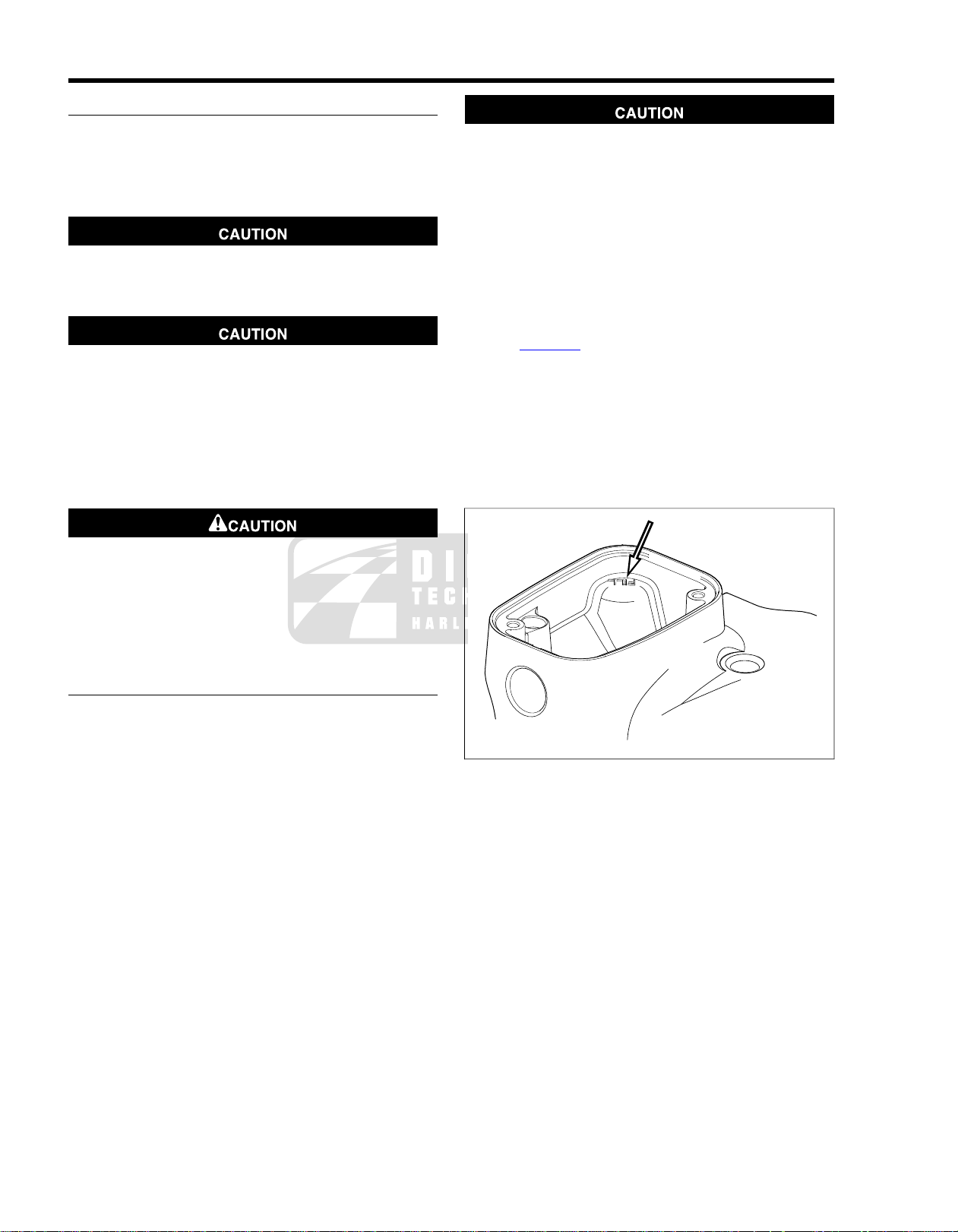
3. See Figure 1-1. If fluid le vel is below FILL LEVEL on ledge
in reservoir, add D.O.T. 4 HYDRAULIC BRAKE FLUID
(Part No. 99953-99A) to raise fluid level. Do not exceed
FILL LEVEL.
4. Carefully place cover gasket and cover on clutch master
cylinder/reservoir.
5. Secure cover with two screws. Tighten screws to 6-8 in-
lbs (0.7-0.9 Nm).
CLUTCH FLUID LEVEL
Even though a clear sight glass in the reservoir cover indicates
low clutch fluid, remove the reservoir cov er to check fluid le vel.
Figure 1-1. Fill Level (Reservoir Cover Removed)
1-2 2008 FLHTCUSE3 Service: Maintenance
Page 17
1.3BLEEDING CLUTCH FLUID LINE
sm03946
1
2
sm03947
DRAINING AND FILLING
Be sure no clutch fluid gets on tires, wheels or brakes
when adding fluid. Traction can be adversely affected,
which could result in loss of control and death or serious
injury. (00294a)
Direct contact of D.O.T. 4 brake fluid with eyes can cause
irritation. Avoid eye contact. In case of eye contact flush
with large amounts of water and get medical attention.
Swallowing large amounts of D.O .T . 4 brake fluid can cause
digestive discomfort. If swallowed, obtain medical attention. Use in well ventilated area. KEEP OUT OF REACH OF
CHILDREN. (00240a)
D.O.T. 4 brake fluid will damage painted and body panel
surfaces it comes in contact with. Alwa ys use caution and
protect surfaces from spills whenever brake work is performed. F ailure to comply can result in cosmetic damage.
(00239b)
• Do not wipe any spilled brake fluid off of finished surf aces.
Always flush the affected components with water (not
soapy).
9. Fill clutch master cylinder/reservoir with D.O.T. 4
HYDRAULIC BRAKE FLUID (Part No. 99953-99A). Initial
fluid level should not exceed FILL LEVEL with reservoir
in a level position.
NOTE
The shelf life of a bottle of unopened D.O.T. 4 HYDRAULIC
BRAKE FLUID is one year.The shelf life of an uncontaminated
bottle that has been resealed is one week.
10. Bleed master cylinder. See 1.3 BLEEDING CLUTCH
FLUID LINE, Bleed Clutch Master Cylinder.
11. Bleed clutch fluid line and secondary actuator. See
1.3 BLEEDING CLUTCH FLUID LINE, Bleed Fluid Line
and Actuator.
Do not allow dirt or debris to enter the master cylinder
reservoir . Dirt or debris in the reservoir can cause improper
operation and equipment damage. (00205c)
1. Cover exhaust with towel and place a suitable pan under
clutch release cover to catch excess clutch fluid.
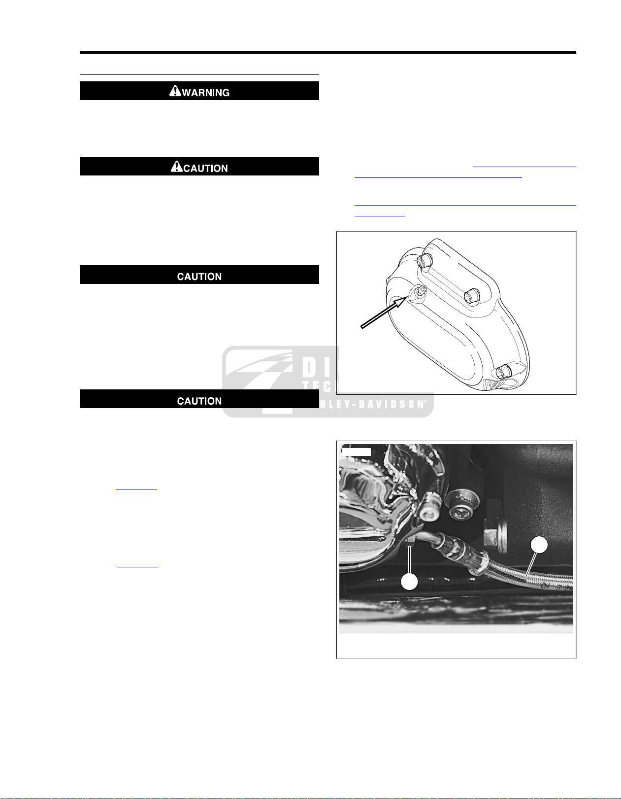
2. See Figure 1-2. Remove plastic cap and loosen bleeder
valve.
3. Run hose from bleeder valve to pan.
4. Loosen the clutch master cylinder/reservoir cover.
5. Allow clutch fluid to drain into pan.
6. See Figure 1-3. Remove flare nut (1) on outside of the
clutch release cover . Discard o-ring and drain fluid line (2)
into pan.
NOTE
Dispose of clutch fluid in accordance with local regulations.
7. Hand tighten valve and replace cap.
8. Install clutch line flare nut with a new o-ring and tighten
to 72-120 in-lbs (8.1-13.6 Nm).
NOTE
When filling an empty clutch fluid line, a Snap-on Basic V acuum
Brake Bleeder with a fitting that mates to the secondary actuator bleeder valve can be used to initially draw the fluid down
the clutch line.
Figure 1-2. Actuator Bleeder Valve
1. Flare nut
2. Clutch fluid line
Figure 1-3. Clutch Fluid Line and Flare Nut
2008 FLHTCUSE3 Service: Maintenance 1-3
Page 18

BLEED CLUTCH MASTER CYLINDER
NOTE
Clutch fluid volume in reservoir actually increases with clutch
wear. Do NOT overfill clutch reservoir.
1. Stand motorcycle upright.Turn handlebars to level reservoir.
2. Add D.O.T. 4 HYDRAULIC BRAKE FLUID (Part No.
99953-99A) to clutch master cylinder/reservoir. Initial fluid
level should not exceed FILL LEVEL with reservoir in a
level position.
NOTE
The shelf life of a bottle of unopened D.O.T. 4 HYDRAULIC
BRAKE FLUID is one year.The shelf life of an uncontaminated
bottle that has been resealed is one week.
D.O.T. 4 brake fluid will damage painted and body panel
surfaces it comes in contact with. Alwa ys use caution and
protect surfaces from spills whenever brake work is performed. F ailure to comply can result in cosmetic damage.
(00239b)
• Do not wipe any spilled brake fluid off of finished surf aces.
Always flush the affected components with water (not
soapy).
4. Fill reservoir to FILL LEVEL and repeat the previous step
three times or more until only a steady flow of clutch fluid
escapes banjo fitting and fluid level in reservoir is at FILL
LEVEL with motorcycle in an upright position.
BLEED FLUID LINE AND ACTUATOR
1. While holding reservoir cover in place:
a. Pump clutch hand lever 5 times.
b. Hold clutch hand lever against handlebar.
c. Run hose from bleeder valve to suitable container.
d. Loosen actuator bleeder valve.
e. Watch bleeder valve for air bubbles.
f. Tighten bleeder valve.
g. Release clutch hand lever.
NOTE
Clutch fluid volume in reservoir actually increases with clutch
wear. Do NOT overfill clutch reservoir.
2. With reservoir level, fill reservoir to FILL LEVEL and repeat
the previous step three times or more until only a steady
flow of clutch fluid escapes bleeder valve and fluid level
in reservoir is at FILL LEVEL with motorcycle in an upright
position.
RETURN MOTORCYCLE TO SERVICE
NOTE
Loosen banjo bolt only enough to allow air bubbles to escape .
Clutch fluid under pressure can squirt a steady stream several
feet.
3. While holding reservoir cover in place:
a. Pump clutch hand lever 5 times.
b. Hold clutch hand lever against handlebar.
c. Hold shop towel under fitting and loosen master cyl-
inder banjo bolt.
d. Watch banjo fitting for air bubbles.
e. Retighten banjo fitting.
f. Release hand lever.
1. Test pressure by squeezing clutch hand lever.
2. Tighten fasteners as follows:
a. Clutch master cylinder banjo bolt to 12.5-14.5 ft-
lbs (16.9-19.7 Nm).
b. Clutch line flare nut to 72-120 in-lbs (8.1-13.6 Nm).
c. Actuator bleeder valve to 12-15 in-lbs (1.4-1.7 Nm).
d. Reservoir cover screws to 6-8 in-lbs (0.7-0.9 Nm).
3. Remove hose from bleeder valve and replace protective
cap.
4. Test ride motorcycle. Incorrect pressure or fluid level can
cause:
a. Dragging clutch.
b. Hard shifting.
1-4 2008 FLHTCUSE3 Service: Maintenance
Page 19

GENERAL
1.4ENGINE LUBRICATION SYSTEM
The engine of this model is initially filled with Screamin' Eagle
SYN3 Synthetic Motorcycle Lubricant.
If oil needs to be added to the engine to bring the fill level to
FULL on the dipstick and SYN3 is not availab le, the first choice
would be to add H-D 360 SAE 20W50 to the SYN3 for engine
lubrication. Although H-D 360 is compatible with SYN3, we
suggest the mixture of the fluids be changed as soon as possible.
If H-D 360 is not available , the second choice would be to add
an acceptable diesel engine oil.We again suggest the mixture
of the fluids be changed as soon as possible. DO NOT add
diesel engine oil to the primary chaincase or transmission.
Refer to Table 1-2.To switch lubricant to H-D 360, completely
drain the SYN3 before filling with H-D 360. A residual amount
of fluid will remain. It is not required to flush out the residual
fluid.
Prolonged or repeated contact with used motor oil may
be harmful to skin and could cause skin cancer. Pr omptl y
wash affected areas with soap and water. (00358b)
If swallowed, do not induce v omiting. Contact a ph ysician
immediately. In case of contact with eyes, immediateley
flush with water. Contact a physician if irritation persists.
(00357b)
Do not switch lubricant brands indiscriminately because
some lubricants interact chemically when mixed. Use of
inferior lubricants can damage the engine. (00184a)
If it is necessary to add oil and the recommended HarleyDavidson lubricant is not available , use an oil certified for diesel
engines.
At the first opportunity, see a Harley-Da vidson dealer to change
back to 100 percent Harley-Davidson oil.
Acceptable diesel engine oil designations include:
• CF-4
• CG-4
• CH-4
• CI-4
The preferred viscosities for the diesel engine oils, in descending order are:
• 20W50
• 15W40
• 10W40
Lubricant
DAVIDSON TYPE
Table 1-2. Recommended Oil Grades
VISCOSITYHARLEY-
HARLEY-
DAVIDSON
RATING
LOWEST
AMBIENT
TEMPERATURE
COLD
WEATHER
STARTS
BELOW
50°F (10°C)
ExcellentAbove 40°F (4°C)HD 360SAE 20W50Screamin' Eagle® SYN3 Synthetic Motorcycle
ExcellentBelow 40°F (4°C)HD 360SAE 10W40H.D. Multi-Grade
GoodAbove 40°F (4°C)HD 360SAE 20W50H.D. Multi-Grade
PoorAbove 60°F (16°C)HD 360SAE 50H.D. Regular Heavy
PoorAbove 80°F (27°C)HD 360SAE 60H.D. Extra Heavy
2008 FLHTCUSE3 Service: Maintenance 1-5
Page 20
1.5CRITICAL FASTENERS
INSPECTION
Inspect critical fasteners, except head bolts:
Table 1-3. Critical Fasteners: 2008 Touring Models
screws
bolts
bolts
screws
nut
master cylinder
master cylinder
Hand controls
inder/handlebar clamp
inder/handlebar clamp screws
screws
Refer to Table 1-3. Tighten all critical fasteners, except head
bolts, to service manual specifications. Replace an y damaged
or missing hardware.
TORQUEFASTENERSYSTEM
81.3-88.1 Nm60-65 ft-lbsFront axle nutAxle
129-142 Nm95-105 ft-lbsRear axle cone nut
16.9-19.7 Nm12.5-14.5 ft-lbsBanjo bolt, rear master cylinderBrakes
19.7-21.7 Nm14.5-16.0 ft-lbsBanjo bolt, front master cylinder
19.7-29.8 Nm14.5-22.0 ft-lbsBanjo bolts, ABS housing
23.1-25.8 Nm17-19 ft-lbsBanjo bolt, brake caliper
9.1-11.3 Nm80-100 in-lbsBrake bleeders
21.7-32.5 Nm16-24 ft-lbsFront brake disc mounting
38.0-51.6 Nm28-38 ft-lbsFront brake caliper mounting
58.3-65.1 Nm43-48 ft-lbsRear brake caliper mounting
8.5-11.5 Nm75-102 in-lbsBrake caliper pad pins
40.7-61.1 Nm30-45 ft-lbsRear brake disc mounting
14.2-16.9 Nm10.5-12.5 ft-lbsRear master cylinder mounting
1.4-1.7 Nm12-15 in-lbsReservoir cover screws, rear
0.9-1.1 Nm8-10 in-lbsReservoir cover screws, front
14.9-20.4 Nm132-180 in-lbsAxle holder nutsFront forks
8.1-9.5 Nm72-84 in-lbsClutch master cyl-
8.1-9.5 Nm72-84 in-lbsBrake master cyl-
4.0-5.1 Nm35-45 in-lbsUpper/lower switch housing
40.7-54.3 Nm30-40 ft-lbsLower clamp (riser) boltsHandlebars
58.3-63.7 Nm43-47 ft-lbsLocknutRear fork pivot shaft
40.7-54.2 Nm30-40 ft-lbsSwingarm bracket bolts
1-6 2008 FLHTCUSE3 Service: Maintenance
Page 21
Engine
Table 1-3. Critical Fasteners: 2008 Touring Models
TORQUEFASTENERSYSTEM
40.7-47.5 Nm30-35 ft-lbsEngine mounting bracket to
cylinder head bolts
24.4-29.9 Nm18-22 ft-lbsTop stabilizer link to top engine
mounting bracket bolt
24.4-29.9 Nm18-22 ft-lbsTop stabilizer link to frame
weldment bolt
24.4-29.9 Nm18-22 ft-lbsFront stabilizer link to frame
weldment bolt
24.4-29.9 Nm18-22 ft-lbsFront stabilizer link to front
engine mounting bracket bolt
20.3-27.1 Nm15-20 ft-lbsCenter front engine mounting
bracket to rubber mount bolt
20.4-27.1 Nm15-20 ft-lbsFront engine mount to frame
crossmember bolts
48.9-54.2 Nm36-40 ft-lbsEngine to front engine mounting
bracket bolts
40.7-47.5 Nm30-35 ft-lbsEngine to transmission bolts
16.9-19.7 Nm12.5-14.5 ft-lbsBanjo boltClutch
8.1-13.6 Nm72-120 in-lbsClutch fluid line flare nut
1.4-1.7 Nm12-15 in-lbsSecondary actuator bleeder
valve
0.7-0.9 Nm6-8 in-lbsReservoir cover screws
2008 FLHTCUSE3 Service: Maintenance 1-7
Page 22

NOTES
1-8 2008 FLHTCUSE3 Service: Maintenance
Page 23

SUBJECT............................................................................................................................PAGE NO.
2.1 SPECIFICATIONS: CHASSIS...................................................................................................2-1
2.2 VEHICLE IDENTIFICATION NUMBER (V.I.N.)..........................................................................2-2
2.3 FOOTBOARDS AND CONTROLS............................................................................................2-3
2.4 HIGHWAY PEGS.......................................................................................................................2-9
2.5 FRONT AXLE COVERS..........................................................................................................2-11
2.6 LOWER TRIPLE CLAMP COVER...........................................................................................2-12
2.7 HANDLEBARS........................................................................................................................2-13
2.8 HANDGRIPS...........................................................................................................................2-20
2.9 CLUTCH MASTER CYLINDER AND RESERVOIR................................................................2-24
2.10 CLUTCH HAND LEVER........................................................................................................2-28
2.11 CLUTCH FLUID LINE............................................................................................................2-29
2.12 SEAT......................................................................................................................................2-31
2.13 RIDER BACKREST...............................................................................................................2-33
2.14 TOUR-PAK.............................................................................................................................2-35
2.15 SADDLEBAGS......................................................................................................................2-38
2.16 SADDLEBAGS LATCH..........................................................................................................2-39
2.17 SADDLEBAG SUPPORTS....................................................................................................2-40
2.18 MUFFLER END CAP.............................................................................................................2-42
CHASSIS
Page 24

NOTES
Page 25
2.1SPECIFICATIONS: CHASSIS
GENERAL
Table 2-1. Dimensions: 2008 FLHTCUSE3
*With 180 lb. (81.7 kg) rider.
Table 2-2.Weight
KGLB.ITEM
MMIN.ITEM
161363.5Wheel base
247897.57Overall length
97038.2Overall width
124.54.9Road clearance
145057.1Overall height
72928.7Saddle height*
* As shipped from the factory
Table 2-3. Capacities
* Front fork is functionally identical to FLHTCU. See Touring
Models Service Manual for appropriate front fork service
procedures.
392864Dry Weight*
5721259GVWR
227500GAWR - Front
375827GAWR - Rear
LITERSU.S.ITEM
22.76 galFuel tank (total)
3.78 L4.0 quartsOil tank with filter
946 mL32 fl. oz.T ransmission (appro ximate)
1100 mL38 fl. oz.Primary (drained)
1330 mL45 fl. oz.Primary (cover removed)
HEIGHTVOLUMEFront Fork*
MMIN.MLOZ
1425.5931910.8
NOTE
Gross Vehicle Weight Rating (GVWR) (maximum allowable
loaded vehicle weight) and corresponding Gross Axle Weight
Ratings (GAWR) are given on a label located on the inside of
the right front frame downtube.
2008 FLHTCUSE3 Service: Chassis 2-1
Page 26
2.2VEHICLE IDENTIFICATION NUMBER (V.I.N.)
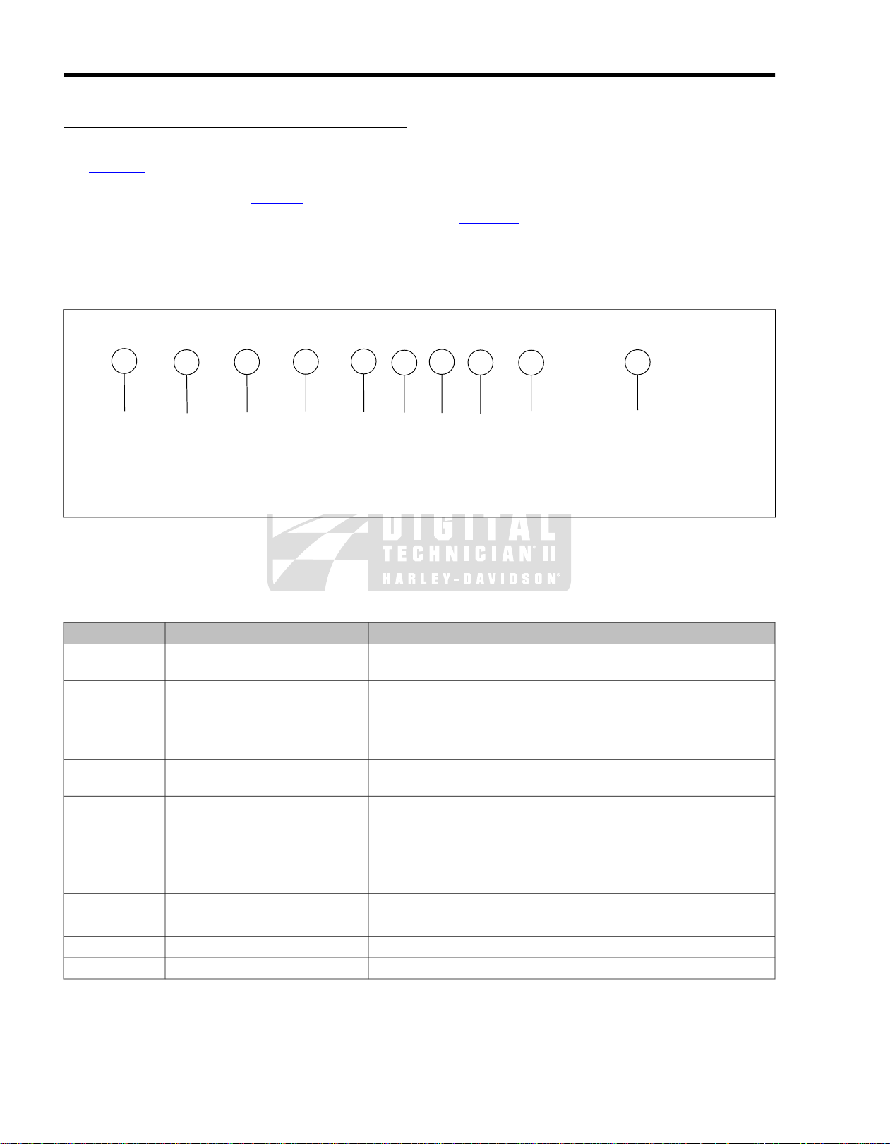
1 HD 1 PR 8 1 7 8 Y 111000
1
2
3
4
5
6
7
8
9
10
om00927
VEHICLE IDENTIFICA TION NUMBER (V.I.N.): FLHTCUSE3
General
See Figure 2-1. A unique 17-digit serial or V ehicle Identification
Number (V .I.N.) is f ound on each motorcycle. F or a description
of each item in the V.I.N., refer to Table 2-4.
Location
The full 17-digit serial or Vehicle Identification Number (V.I.N.)
is stamped on the right side of the frame backbone at the rear
of the steering head under the main wiring harness. A label
bearing the V.I.N. code is also affixed to the left side of the
steering head.
Abbreviated V.I.N.
An abbreviated V.I.N. is stamped on the left side of the crankcase below the engine cylinders.
Example: PR88111000
See Figure 2-1 for the complete V.I.N. as it appears on the
steering head.
NOTE
Always give the full 17-digit Vehicle Identification Number when
ordering parts or making any inquiry about your motorcycle.
Figure 2-1.Typical Harley-Davidson V.I.N.: 2008 FLHTCUSE3 Models
Table 2-4. Harley-Davidson V.I.N. Breakdown: 2008 FLHTCUSE3 Models
POSSIBLE VALUESDESCRIPTIONPOSITION
1=Originally manufactured for sale within the United StatesMarket designation1
5=Originally manufactured for sale outside of the United States
HD=Harley-DavidsonManufacturer2
1=Heavyweight motorcycle (901 cc or larger)Motorcycle type3
Model4
PR=FLHTCUSE3 Screamin' Eagle® Ultra Classic® Electra Glide
PR=FLHTCU3-CVO (Japan only)
4=96 cu. in. (1584 cc) air cooled, fuel injectedEngine type5
8=110 cu. in. (1800 cc) air cooled, fuel injected
1=RegularIntroduction date6
2=Mid-year
3=California/regular
4=Cosmetic changes and/or special introductory date
5=California/cosmetic changes and/or special introductory date
6=California/mid-year
Can be 0-9 or XV.I.N. check digit7
8=2008Model year8
Y=York, PA U.S.A.Assembly plant9
VariesSequential number10
®
2-2 2008 FLHTCUSE3 Service: Chassis
Page 27

RIDER FOOTBOARDS
sm03952
sm03953
Removal
NOTES
• Unless the footboards are being replaced, they do not
have to be removed from footboard brackets.
• See Figure 2-2.The right and left footboard frame mounts
allow a small variance in height and angle of footboards.
If footboard brack ets are to be remov ed, note the position
in the adjustment holes in the frame mounts. Reinstall
footboard brackets in same positions.
1. Position motorcycle upright on a lift or jack stand so that
the motorcycle is not resting on jiffy stand.
2. See Figure 2-3. With footboards in up position, use a
screwdriver to work cover rubber collars out through f ootboards.
3. See Figure 2-4. Remove front and rear footboard pivot
bolts (3) and nuts (4) and remove footboards.
4. Remove fasteners (12), lockwasher (8) and left rear footboard bracket (14).
NOTE
Fasteners for left rear bracket thread through the jiffy stand
bracket.
5. Remove screw (7), lockwasher (8), washer (9) and left
front footboard bracket (13).
6. Remove screws (7), lockwashers (8), washers (9) and
both front (10) and rear (11) right footboard brackets.
2.3FOOTBOARDS AND CONTROLS
Figure 2-2. Footboard Position Adjustment Holes
Figure 2-3. Footboard Insert Rubber Collars
2008 FLHTCUSE3 Service: Chassis 2-3
Page 28

2
11
4
5
8
14
8
3
9
7
13
10
6
1
8
9
12
sm03954
8.1. Lockwasher (5)Footboard insert (RH)
2. 9.Footboard insert (LH) Washer (3)
10.3. Front support bracket (RH)Pivot bolt (4)
4. 11.Locknut (4) Rear support bracket (RH)
12.5. Fastener (2)Footboard bottom (RH)
6. 13.Footboard bottom (LH) Front support bracket (LH)
14.7. Rear support bracket (LH)Screw (3)
Figure 2-4. Rider Footboards
Installation
NOTE
Avoid contacting chrome surfaces with abrasive materials
(stones, sand, etc.) as damage will result.
1. Install left front footboard brack et with washer , lockwasher
and screw.Tighten screw finger-tight.
2. Install fastener and lock washer through the left rear footboard bracket through the jiffy stand brac ket into the boss
in the frame.
3. Install fastener and lockwasher from the inside of the fr ame
through the jiffy stand bracket and into the left rear footboard bracket.
2-4 2008 FLHTCUSE3 Service: Chassis
4. Tighten both left rear footboard bracket fasteners to 1520 ft-lbs (21-27 Nm).
5. Install left footboard bottom assembly onto footboard
brackets. Install and tighten pivot bolts and locknuts to
60-80 in-lbs (6.8-9.0 Nm).
6. Tighten left front footboard brack et cap screw to 30-35 ftlbs (41-47 Nm).
7. Install right footboard brackets with w ashers, lockwashers ,
and cap screws.Tighten screws finger-tight.
8. Install right footboard bottom assembly onto footboard
brackets. Install and tighten pivot bolts and locknuts to
60-80 in-lbs (6.8-9.0 Nm).
Page 29
9. Tighten right footboard bracket cap screws to 30-35 ft-
sm04242
4
3
2
5
1
sm03963
sm04244
lbs (41-47 Nm).
10. Moisten footboard cover rubber collars with soapy water.
11. With footboard bottom in up position, hold new f ootboard
insert assembly in position.
12. From underside of footboard use a pliers to pull each
rubber collar through footboard hole.
SHIFT LEVERS
Replace Pegs
1. See Figure 2-5. Remove the fastener and the shift lever
peg.
2. See Figure 2-6. Assemble chrome cover (2) over rubber
pad (1).
3. Insert sleeve (4) and fasten to shift le ver with fastener (3)
and lockwasher (5).
4. Rotate pegs for rider posture and tighten Torx fastener to
14-16 ft-lbs (19-21 Nm).
1. Rubber pad
2. Chrome cover
3. Fastener
4. Sleeve
5. Lockwasher
Figure 2-6. Shift Lever Peg
Replace Heel-Toe Shift Levers
1. See Figure 2-8. Loosen and remove Allen head clamp
bolts.
2. Pull shift levers off splined shaft.
3. Position shift levers on splined shaft for rider posture.
4. Install and tighten clamp bolts to 18-22 ft-lbs (25-29 Nm).
Figure 2-5. Shift Lever Peg
Figure 2-7. Shift Levers
2008 FLHTCUSE3 Service: Chassis 2-5
Page 30

sm03964
1
5
8
2
6
3
4
7
sm03962
Figure 2-8. Heel-Toe Shift Lever Clamp Bolts
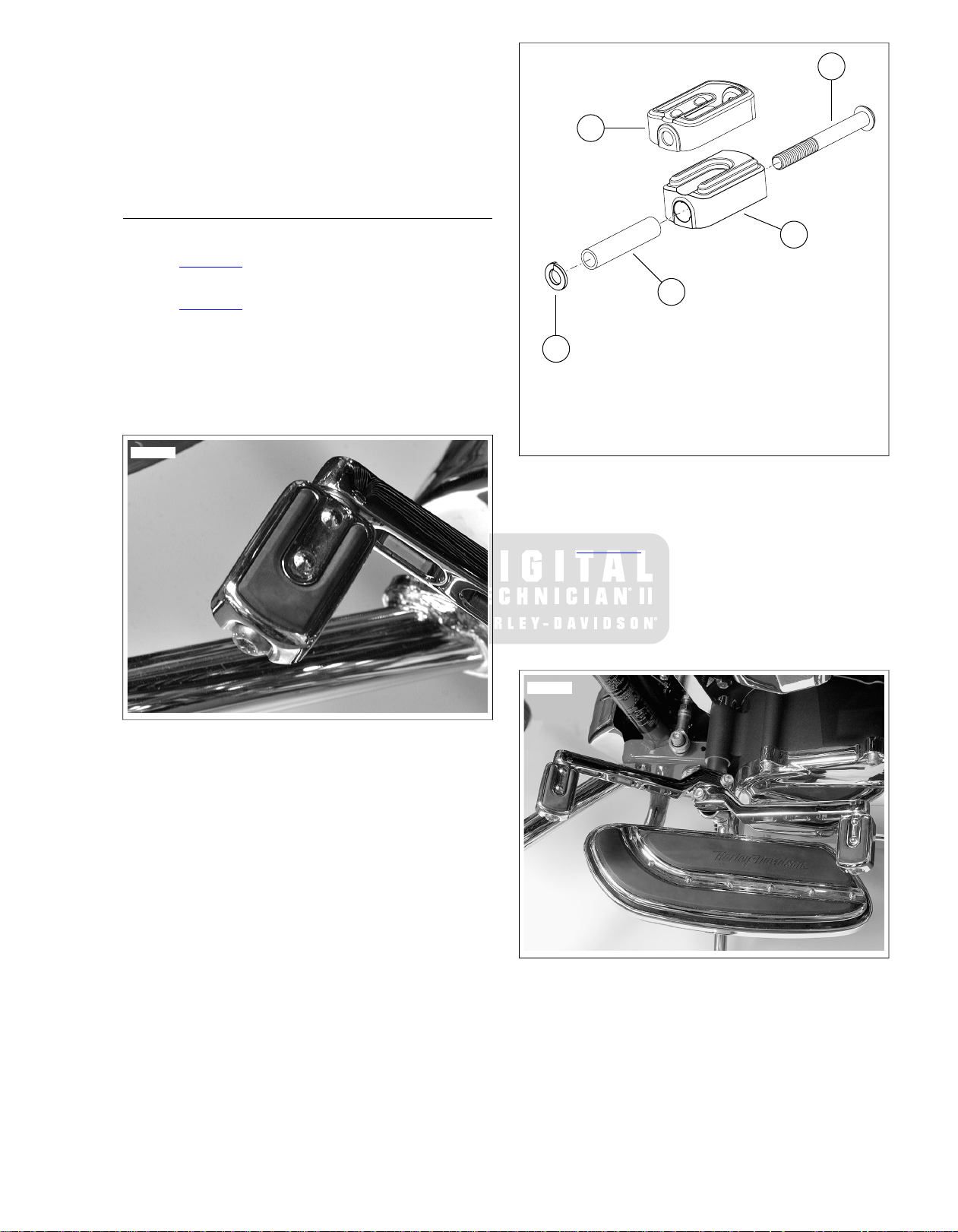
REAR BRAKE PEDAL
1. See Figure 2-9. Remove screws (1), brake pedal cover
(2) and pad (3) from metal backing plate (4).
2. Remove acorn nut (5), offset washer (6), metal backing
plate and fastener (7) from foot brake lever (8).
3. Install metal backing plate to foot brak e le ver. Secure with
offset washer and acorn nut. Tighten nut to 25-29 ftlbs (33.9-39.4 Nm).
4. Assemble chrome cover and rubber pad to metal bac king
plate. Secure with screws. Tighten to 20-22 in-lbs (2.3-
2.5 Nm).
1. Screw (2)
2. Chrome cover
3. Rubber pad
4. Metal backing plate
5. Acorn nut
6. Offset washer
7. Fastener
8. Foot brake lever
Figure 2-9. Rear Brake Pedal
ADJUST ABLE PASSENGER FOOTBO ARDS
Remove
1. See Figure 2-10. Remove the upper (1) adjustment bolt,
wave spring and the footboard assembly.
2. Remove the lower adjustment bolt (3), wave spring and
the rotating arm (2).
3. Remove screw and lockwasher to remove footboard
bracket from rear fork pivot bracket.
Disassemble
1. See Figure 2-11. Pivot support 90° to access and back
set screw out of insert.
2. Pull the insert out of the footboard.
3. Press the pivot pins into the center cavity and remove.
NOTE
With the support and the footboard base at 90°, squeeze the
support against the footboard to release tension on the pins.
It maybe necessary to tap the pins with a brass drift.
4. Retain ball and spring from hole in support.
2-6 2008 FLHTCUSE3 Service: Chassis
Page 31

1
3
2
sm03955
1. Upper adjustment bolt
sm03956
1
3
2
sm03957
sm03958
2. Rotating arm
3. Lower adjustment bolt
Figure 2-10. Passenger Footboard Adjustment Bolts
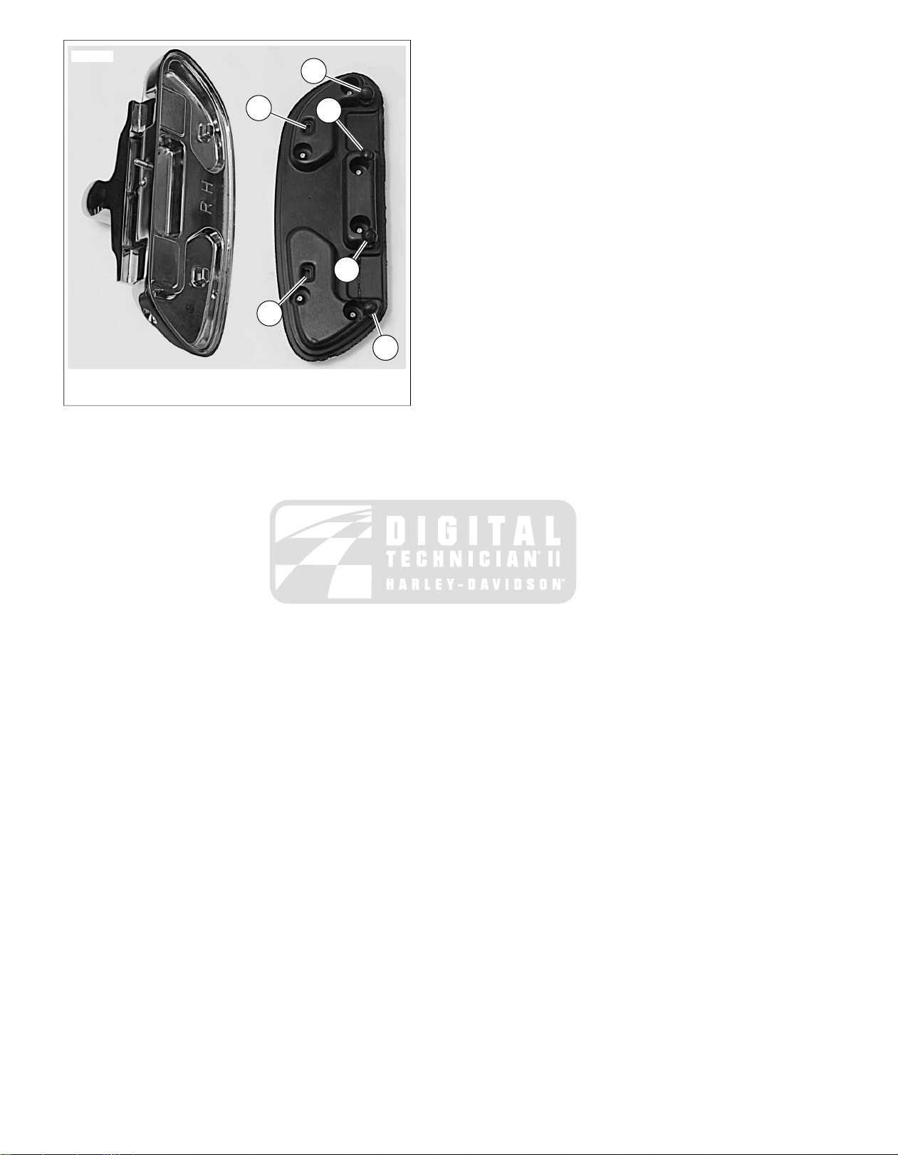
4. See Figure 2-13. Release the support and footboard to
hold the pins centered in the lugs of the footboard.
5. See Figure 2-14.With soapy water, moisten rubber beads
(1) and rubber sockets (2) on new insert.
6. Position in f ootboard and press on insert until beads have
engaged footboard pins and footboard pins ha ve engaged
insert sockets.
Figure 2-11. Insert Set Screw
Assemble
1. See Figure 2-12. Place spring (1) into hole (2) in support
and place ball (3) on top of spring.
2. Orient the support to the footboard to fit the rotating arm.
3. Install pivot pins from the outboard side. Center the pins
To slide the pins in the lugs, squeeze the support against the
footboard to compress the spring and relieve the tension on
the pins. It maybe necessary to tap the pins in place with a
brass drift.
Mate the support to the floorboard to capture the ball and
spring.
in lugs of footboard.
NOTE
1. Spring
2. Hole
3. Ball
Figure 2-12. Support and Footboard
Figure 2-13. Centered Pin
2008 FLHTCUSE3 Service: Chassis 2-7
Page 32
1
2
1
2
1
1
sm03961
1. Rubber beads
2. Rubber sockets
Figure 2-14. Footboard and New Insert
Install
1. Insert locating pin of footboard bracket into hole in rear
fork pivot bracket.
NOTE
Passenger footboards can be installed in one of three positions .
To move footboards to a new position, remove plastic plugs
from holes in rear fork pivot bracket as necessary.
2. Install screw and lockwasher.Tighten to 30-35 ft-lbs (41-
47 Nm).
3. Install rotating arm and lower adjustment bolt with wave
spring.
4. Install footboard assembly with upper adjustment bolt and
wave spring.
Adjust
1. Raise the footboard and loosen the lower adjustment bolt
enough to rotate the rotating arm. Rotate arm to desired
footboard height.
NOTE
Passenger footboards may adjusted to one of five positions.
2. Tighten lower adjustment bolt to 25-30 ft-lbs (34-40 Nm).
3. Loosen upper adjustment bolt enough to allow footboard
mount to be rotated.
NOTE
The horizontal position of tilt of the footboard may be further
adjusted for passenger comfort.
4. Move footboard mount to desired footboard horizontal
position or tilt.
5. Tighten upper adjustment bolt to 25-30 ft-lbs (34-40 Nm).
2-8 2008 FLHTCUSE3 Service: Chassis
Page 33
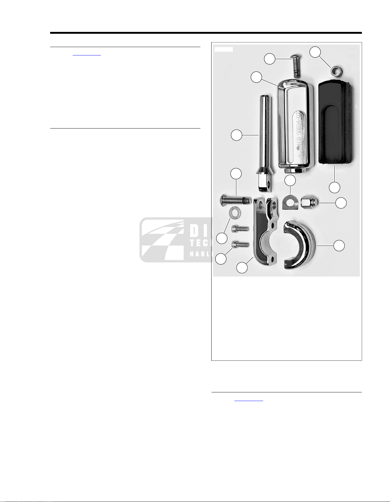
DISASSEMBLY
6
5
4
8
7
11
2
12
3
1
10
9
sm03965
1. See Figure 2-15. Remo ve the end scre w (4) and slide the
chrome housing (5) off the mounting peg (6).
2. Push the rubber pad (7) and the bushing (8) straight out
of the chrome housing.
3. Remove the Allen head screw (9), washer (10) and the
decorative nut (11).
4. Remove the mounting peg and the spring washer (12).
Save the spring washer.
REMOVING CLAMP
1. Remove the Allen head clamp screws (1).
2. Separate the clamp bracket (2) from the mount bracket
(3) to remove the highway peg from the engine guard.
2.4HIGHWAY PEGS
1. Allen head clamp screws
2. Clamp bracket
3. Mount bracket
4. End screw
5. Chrome housing
6. Mounting peg
7. Rubber pad
8. Bushing
9. Allen head screw
10. Washer
11. Nut
12. Spring washer
Figure 2-15. Highway Peg
INSTALLING CLAMP
1. See Figure 2-16. Use a grease pencil to draw a line (1)
on engine guard 6.5 in. (165 mm) from top of upper rail.
2. Clamp the brackets to the engine guard just below the line
with the brackets at a 25° (2).
3. Tighten the clamp screws to 14 ft-lbs (19 Nm).
4. Clean off grease pencil mark.
2008 FLHTCUSE3 Service: Chassis 2-9
Page 34
NOTES
25
o
25
o
40
o
2
3
1
sm03966
1
2
sm03967
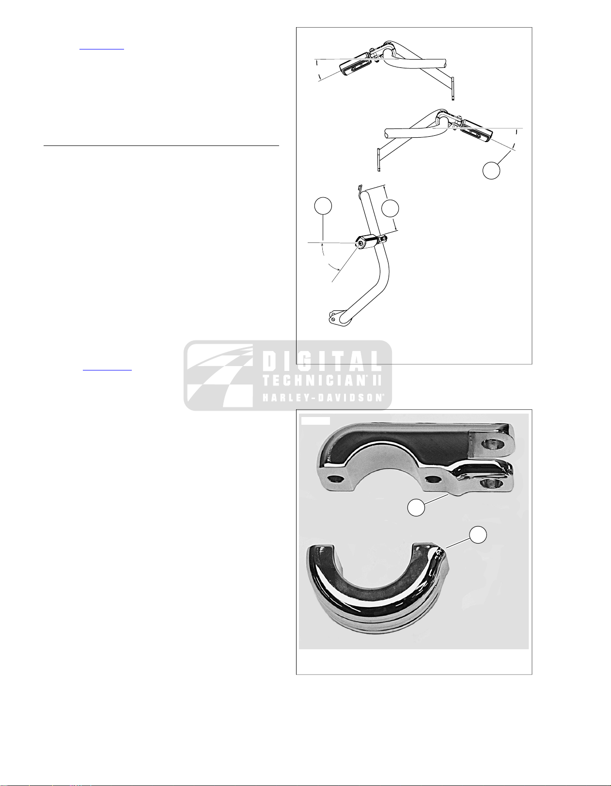
• See Figure 2-17. Match the flair (1) of the clamp bracket
to the bevel (2) of the mount bracket.
• Orient the highway pegs so that he button head Allen head
screw and the two Allen head bracket fasteners face forward and the decorative nut faces the rider.
• Do not position the highway pegs so that the mounting
brackets contact the fairing lowers.
ASSEMBLY
1. Apply LOCTITE 243 THREADLOCKER (blue) to the end
threads of the Allen head screw.
2. With the square edge of the spring washer facing the slot,
hold the spring washer to the pivot hole of the mounting
peg.
3. Orient the round edge of the pivot flat upward and install
with the Allen head screw , washer and n ut.Tighten to 1419 ft-lbs (19-25 Nm).
4. Slip the bushing into the hole in the rubber pad.
5. Fit the pattern of the rubber pad to the metal tang of the
chrome housing and squeeze the rubber pad and bushing
into the housing.
6. Slide the chrome housing and rubber pad onto the
mounting peg.
7. Apply LOCTITE 243 THREADLOCKER (blue) to the end
screw.
8. See Figure 2-16. For rider posture, rotate footpeg
approximately 40° (3) from horizontal.Tighten end screw
to 19 ft-lbs (26 Nm).
1. 6.5 in. (165 mm)
2. 25°
3. 40°
Figure 2-16. Highway Peg Mounting
2-10 2008 FLHTCUSE3 Service: Chassis
1. Clamp flair
2. Mount bevel
Figure 2-17. Clamp and Mount Brackets
Page 35

REPLACEMENT
sm03968
1. See Figure 2-18. Loosen but do not remove set screw
under cover. Remove cover.
2. Remove set screws from cover.
3. Liberally apply LOCTITE 262 THREADLOCKER (red) to
threads of set screw.
4. Orient cover over axle end so that set screw is on the
bottom and will tighten down against a flat on the axle nut.
5. Install and tighten set screw to 60-84 in-lbs (6.8-9.5 Nm).
6. Repeat for opposite side.
2.5FRONT AXLE COVERS
Figure 2-18. Front Axle Cover Set Screw
2008 FLHTCUSE3 Service: Chassis 2-11
Page 36

REPLACEMENT
1
3
2
5
4
sm03969
1. See Figure 2-19. Loosen b ut do not remove the two scre ws
(1) on the backside of the lower triple clamp cover (3).
2. Remove screw (4) through brake line manifold on bottom
of triple clamp cover.
3. Remove two loosened screws (1) with washers (2) and
remove cover.
4. To replace cover, fit cover inside bottom of nacelle and
around lower triple clamp (5). Hold in place.
5. Install screws (1) and washers (2). Tighten finger-tight
only. Install screw (4) through brake line manifold and
cover. Tighten finger-tight only. Verify that cover is snug
against rear surface of lower triple clamp.
NOTE
Plastic plugs in locator holes in rear surface of triple clamp can
cause interference with cover.Verify that center plug has been
removed.
6. Tighten screws (1) to 70-110 in-lbs (7.9-12.4 Nm).
7. Tighten screw (4) to 120-180 in-lbs (13.6-20.4 Nm).
8. V erify that brak e line does not rub on cover. Adjust line or
cover as necessary.
2.6LOWER TRIPLE CLAMP COVER
1. Screw (2)
2. Washer (2)
3. Lower triple clamp cover
4. Screw
5. Lower triple clamp
Figure 2-19. Lower Triple Clamp Cover
2-12 2008 FLHTCUSE3 Service: Chassis
Page 37
2.7HANDLEBARS
1
5
3
4
2
sm03970
REMOVAL
T o prevent accidental vehic le start-up, whic h could cause
death or serious injury, remove main fuse before proceeding. (00251b)
1. Remove left saddlebag, left side cover and maxi-fuse.
2. Remove outer fairing and fairing cap. See FAIRING CAP
in Touring Models Service Manual.
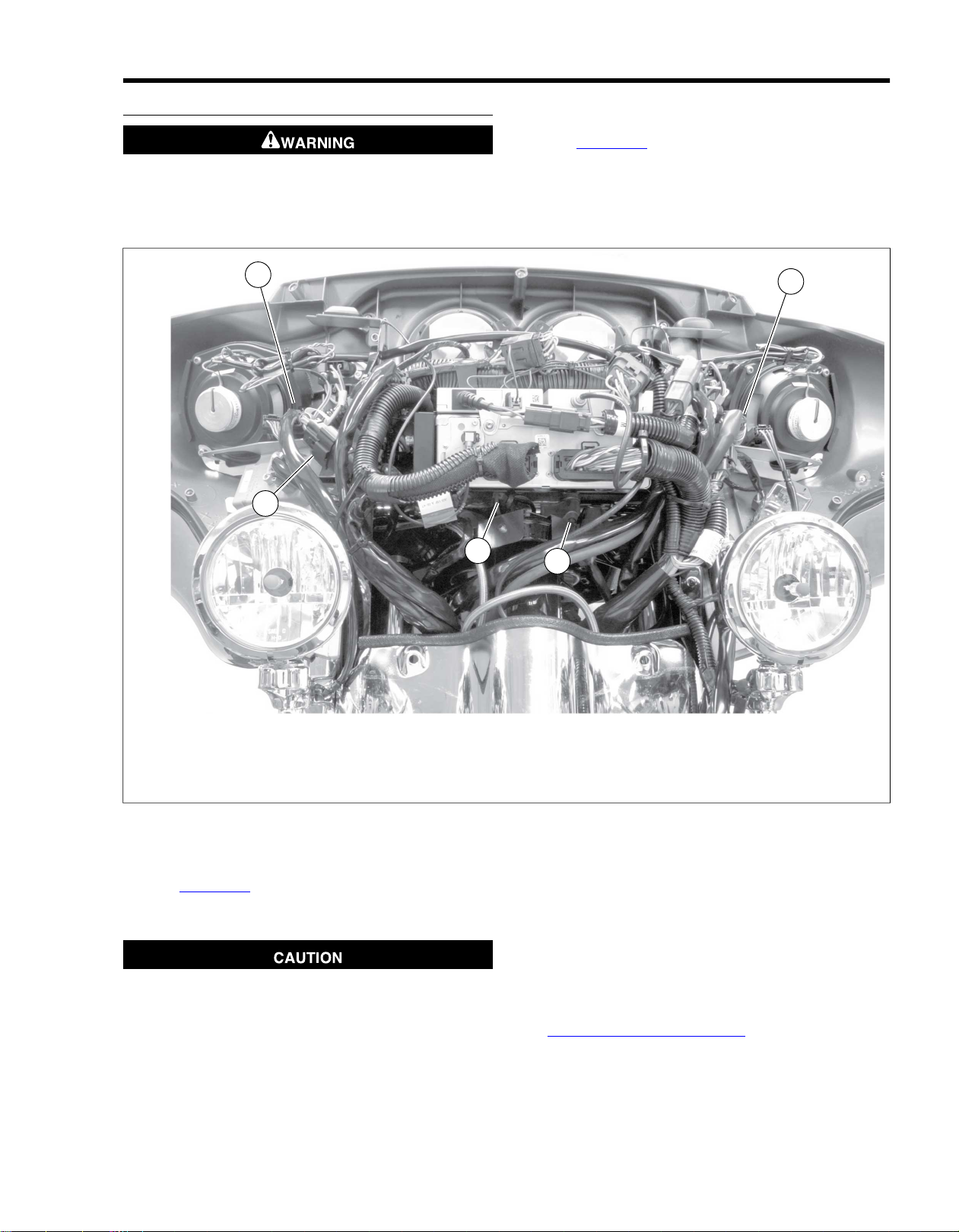
3. See Figure 2-20. Separate handlebar switch connectors
[24] (1) and [22] (2). Separate heated handgrip power
harness connector [189] (3). Disengage connector housings from locating pins. Separate twist grip sensor (TGS)
connector [204] (5).
1. Left handlebar switch connector [24]
2. Right handlebar switch connector [22]
3. Handgrip heater power connector [189]
4. Handgrip heater interconnect [206]
5. Twist grip sensor connector [204]
Figure 2-20. Handlebar Control Connector Locations
4. See Figure 2-21. Squeeze front brake lever and insert a
5/32 in. (4 mm) thick cardboard insert (2) between front
brake lever and lever bracket.
Do not remove or install the master cylinder assembly
without first positioning a 5/32-inch (4 mm) thick insert
between the brake lever and lever bracket. Removing or
installing the master cylinder assembly without the insert
in place may result in damage to the rubber boot and
plunger on the front stoplight switch. (00324a)
5. Remove fasteners securing handlebar clamp to master
cylinder and front brake lever.
6. Protect chrome and painted surfaces and tie master cylinder, reservoir and brake line out of the way.
7. Remove fasteners and w ashers securing handlebar clamp
to clutch lever bracket.
8. Protect chrome and painted surfaces and tie master cylinder, reservoir and clutch fluid line out of the way.
9. Remove Advanced Audio Radio assembly. See
8.13 ADVANCED AUDIO RADIO.
10. Remove upper handlebar clamp and remove handlebar
with wire harnesses from motorcycle.
2008 FLHTCUSE3 Service: Chassis 2-13
Page 38

NOTE
2
1
sm04667
2
1
3
4
6
5
sm04670
If handlebar rubber mounts require service, see HANDLEBARS
in the Touring Models Service Manual.
1. Groove
2. 5/32 in. (4 mm) thick cardboard insert
Figure 2-21. Cardboard Insert
DISASSEMBLY
NOTE
To release twist grip, a slight tug may be necessary.
9. Pull right grip off end of handlebar.
10. See Figure 2-23. Lightly lubricate conduits and tape with
glass cleaner.
11. Gently pull twist grip sensor (TGS) out of handlebar, along
with the right handgrip heater harness.
12. Gently pull left handgrip out of handlebar, along with left
handgrip heater harness.
13. Pull left and right switch control harnesses through
handlebar.
14. Unwrap electrical tape and wire from terminals.
15. Repair or replace switches and socket wires as necessary.
See HANDLEBAR SWITCHES in Touring Models Service
Manual for handlebar switch repair procedures.
1. Place handlebar assembly on work bench.
2. See Figure 2-22. Cut and discard cable straps.
3. Separate heated handgrip interconnect harness connector
[206] (4).
4. Remove terminals and wire leads from handlebar switch
connectors [22, 24] and twist grip sensor (TGS) connector
[204].
NOTE
See APPENDIX B, MOLEX CONNECTORS in Touring Models
Service Manual for service procedures.
5. Remove terminals and wire leads from heated handgrip
power connector [189] (3) and interconnect harness connector [206] (4).
NOTE
See APPENDIX B DEUTSCH ELECTRICAL CONNECTORS
in Touring Models Service Manual for Service Procedures.
6. Slide boots (2) off switch control wiring harnesses. Save
boots for assembly.
7. Wrap terminal ends of each wiring harness tightly in elec-
trical tape to protect terminals from damage as harness
is removed from handlebar.
NOTES
• Forming too large a bulge with electrical tape at end of
wiring harness can make it difficult to extract harness from
handlebar.
• Option: Attach mechanic's wire to the terminal/wire leads.
After drawing the leads through the handlebar, remove
the tape and leads. Leave the mechanic's wire in the
handlebar for installation.
8. Remove upper and lower f asteners securing left and right
switch control housing halves to handlebar.
1. LH switch control connector [24] (gray)
2. Boot (2)
3. Heated handgrip power connector [189]
4. Heated handgrip interconnect connector [206]
5. RH switch control connector [22] (black)
6. Twist grip sensor connector [204]
Figure 2-22. Handlebar Harness Assembly
ASSEMBLY
Pull Wire Leads
NOTES
• If mechanics wire remains in handlebars, attach wire lead
bundles and pull mechanic's wire to draw wire leads back
through handlebars. and out center of handlebar. Carefully
remove mechanic's wire to avoid damage to terminals.
• Liquid glass cleaner may be used to aid in pulling wires
through conduit.
• Make sure grommets are in place in oval holes near each
end of handlebar before feeding harnesses into handlebar .
• It is best to pull all the harnesses for one end of handlebar
at a time. However, if you wish to pull only one harness
2-14 2008 FLHTCUSE3 Service: Chassis
Page 39
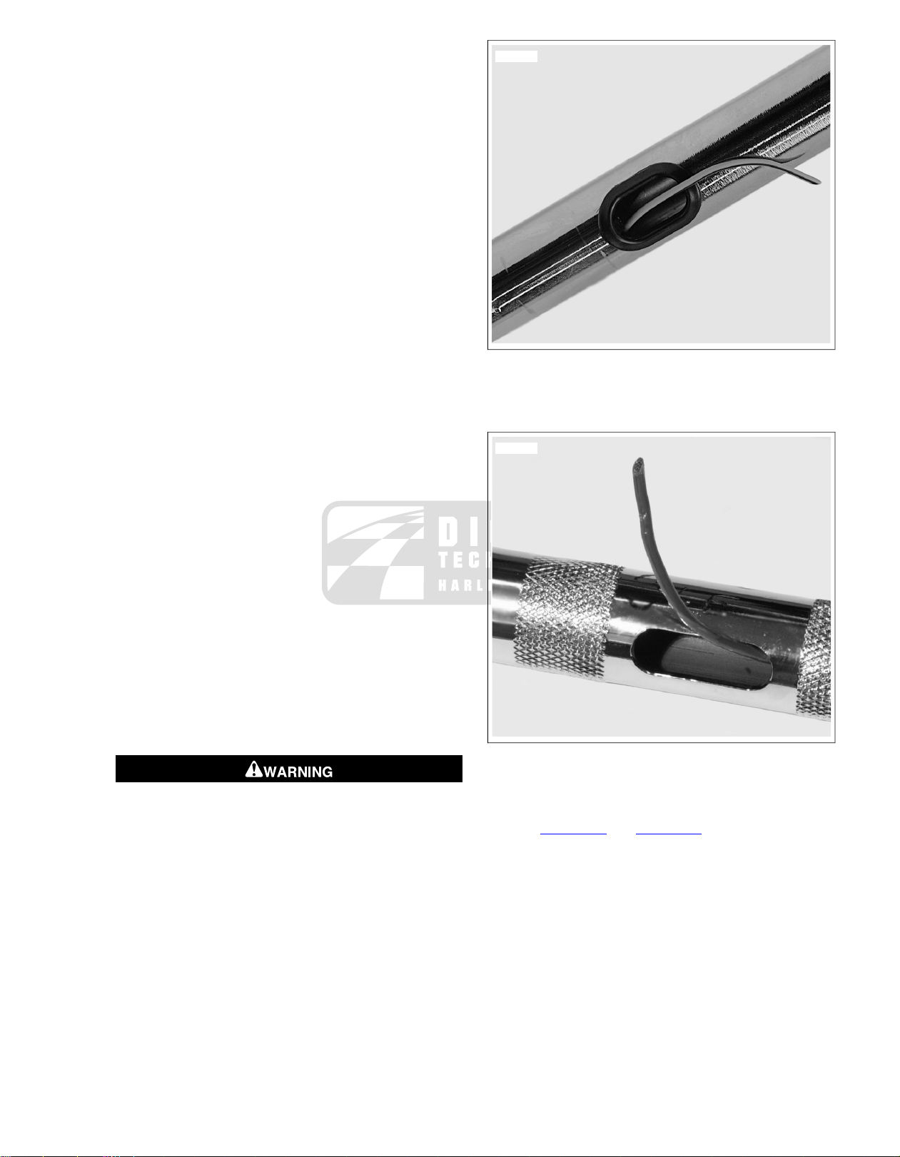
at a time, pull smaller harnesses first, then larger har-
sm03974
sm03976
nesses.
• As you pull on wire leaders, assist the process by gently
feeding harnesses into handlebar at other end.
• If resistance is felt, do not pull too hard on wire leader as
this may damage wires and/or terminals, or dislodge leader
from harness.
1. Cut five lengths of mechanic's wire, each approximately
3 ft (91.4 cm) long. These will be used as har ness wire
leaders.
2. Feed two wire leaders through grommeted hole near left
end of handlebar and one wire leader through left end of
handlebar tube.
3. Feed one wire leader through grommeted hole near right
end of handlebar and one wire leader through right end
of handlebar tube.
4. Extract ends of all wire leaders through center hole. Secure
leaders at center hole so they cannot be accidentally pulled
back through handlebar.
5. Make sure grommets are installed in oval holes near each
end of handlebar.
6. Secure each wire leader to its harness at ends of
handlebar as follows. Neatly wrap socket terminals and
wires of each harness with a few twists of the leader wire:
a. Left side: Attach wire leader extending from left end
of handlebar tube to left handgrip interconnect harness. Attach other two wire leaders (extending from
grommeted hole near left end of handlebar), one to
left switch control harness and the other to left handgrip power harness.
b. Right side:Tape right handgrip interconnect harness
terminals to TGS harnesses. Attach wire leader
extending from right end of handlebar tube to TGS
harness. Attach other wire leader (extending from
grommeted hole near right end of handlebar) to right
switch control harness.
Figure 2-23.Wire Leader through Grommet at Hand Grip
End of Handlebar
7. Wrap wires and terminals of each harness tightly with
electrical tape to protect wires and terminals when
installing harnesses in handlebar.
Grommets in each of the wiring holes in the handlebar
must remain in position after routing the wiring through
the handlebar. Operation without the grommets in place
can damage wires, causing a short circuit which could
result in death or serious injury. (00416d)
8. Lubricate wire conduits with glass cleaner. Grasp end of
wire leader and gently pull wire bundles through grommets
and handlebar ends to the handlebar center hole. Pull
harnesses until left heated handgrip and TGS are fully
seated on ends of handlebar, and no excess slack exists
in switch control harnesses.
Figure 2-24.Wire Leader through Center of Handlebar
Install Switch Housings
1. See Figure 2-25 and Figure 2-26. Orient wires in switchhousings:
a. Right hand side: the RUN and STOP wires are
wrapped over the front of the handlebar, back and
into the handlebar through the grommet. Make sure
the wires run outboard of the clamping post cast into
the inside of the lower housing.
b. Left hand side: the HORN and HI/LO BEAM wires are
also wrapped over the front of the handlebar, back
and into the handlebar through the grommet. Make
sure the wires run inboard of the clamping post cast
into the inside of the lower housing.
2008 FLHTCUSE3 Service: Chassis 2-15
Page 40
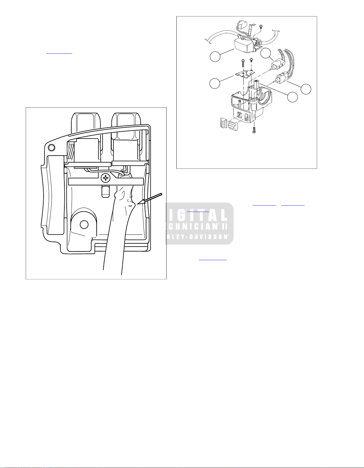
2. Loosely install left and right switch housings onto
sm03977
1
4
2
3
5
sm03978
handlebar and over inboard ends of heated handgrips.
3. Gently pull on wire leaders to remove any e xcess slac k in
harnesses. Unwrap tape and mechanic's wire.
4. See Figure 2-22. Secure wire harnesses at exit from center
of handlebar with cable strap.
5. Reinstall boot (2) on each switch control harness. Secure
with cable strap.
6. Fit wire seal into back of Deutsch socket housings . See
APPENDIX B DEUTSCH ELECTRICAL CONNECTORS
in Touring Models Service Manual.
1. Right turn signal control and wiring
2. Cruise control switch
3. Mode select switch
4. Lower bracket
5. Clamping post
Figure 2-26.Wiring in Lower Right Hand Control Housing
Figure 2-25. Run/Stop Switch Wiring in Upper Right Hand
Control Housing
Install Wire Lead Terminals
1. Following color codes in Table 2-5, Table 2-6 and
Table 2-7, insert terminals into numbered chambers in
connector housings.
NOTE
See the Service Manual for connector assembly guidelines.
2. Gently tug on wire ends to verify that all terminals are
locked.
3. See Figure 2-22. Mate handgrip interconnect harness
connectors [206]. Secure interconnect harness connector
assembly (4) to right hand switch control harness with
cable strap.
4. Pull slack from harnesses and secure together with a cable
strap where harnesses exit center of handlebar.
2-16 2008 FLHTCUSE3 Service: Chassis
Page 41
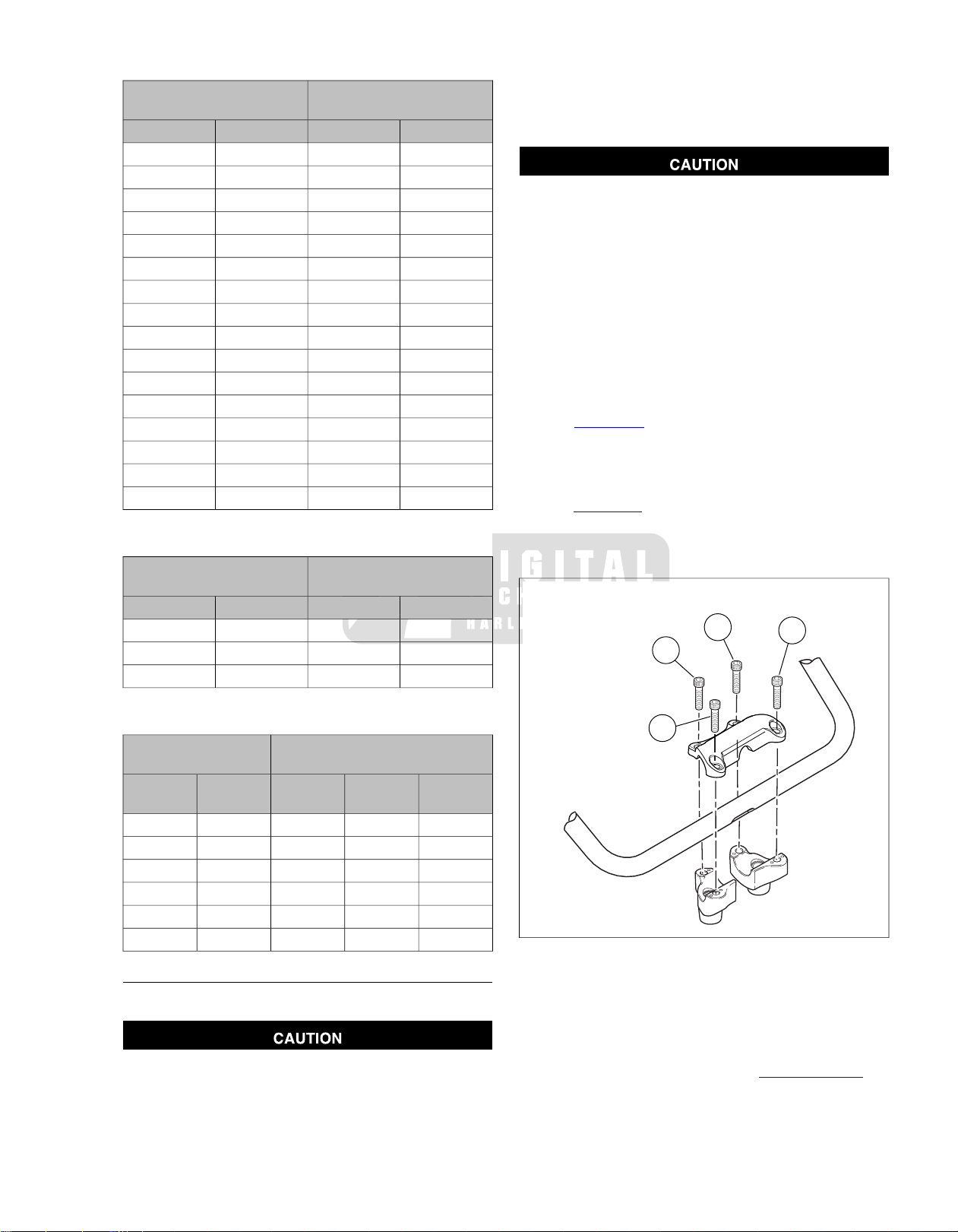
Table 2-5. Handlebar Switch Connectors
2
1
4
3
sm04495
LH CONNECTOR [24]
(16-WAY, GRAY)
Table 2-6. Left Heated Hand Grip Connectors
INTERCONNECT [206]
(2-WAY, BLACK)
RH CONNECTOR [22]
(12-WAY, BLACK)
MAIN POWER [189]
(3-WAY, BLACK)
1. Carry handlebar with internal wire harnesses and control
housings to the motorcycle.
2. Set handlebar on lower clamps and loosely install upper
handlebar clamp and fasteners. P osition wires so they exit
CAVITY NO.WIRE COLORCAVITY NO.WIRE COLOR
1O/W1O/W
2R/BE2Y
3GY3BE
4W/BK4W
5W/BN5W/V
6BK/R6BK/R
7BN/W7V/BK
8GY/W8BN/BK
9PK/W9PK/W
10V/BK10GN/BE
11W/BE11GY/GN
12BE/BK12BK
--13V/BK
--14O/BK
--15-
--16-
CAVITY NO.WIRE COLORCAVITY NO.WIRE COLOR
AO/W1BK
BR2BK/W
CBK--
under radio to front of vehicle from between risers.
Using excessive force to adjust handlebar can result in
damage to handlebar or clamp. (00444b)
NOTE
If handlebars are positioned for a rider of normal size, postpone
adjustment until rider has checked their position. If customer
requests changing handlebar position, perform the adjustment
before delivering the motorcycle.
3. Center handlebar laterally (sideways) in clamps.
4. Snug front fasteners until upper clamp contacts lower
clamps.
5. Position handlebar for rider posture.
6. See Figure 2-27. In sequence sho wn, tighten fasteners to
16-20 ft-lbs (20.3-27.1 Nm).
7. Route wire harness and mate left [24] and right [22] con-
nector socket and pin housings.
8. See Figure 2-20. Mate heater and TGS connectors to main
harness.
9. Secure with cable straps as necessary.
Table 2-7.Twist Grip Sensor (TGS) Connectors
INTERCONNECT [206]
(2-WAY, BLACK)
TERMINALWIRE
COLOR
WIRE
COLOR
TGS [204]
(6-WAY, BLACK)
TERMINALCONDUIT
COLOR
1YBK1BK
2YW2BK/W
3YR-4BKBK-5BKW-6BKR--
INSTALLING HANDLEBARS
Clamp Handlebars to Risers
Improperly aligned handlebars can contact the fuel tank
when turned to the left or right. Contact with the fuel tank
can cause cosmetic damage. (00372a)
Figure 2-27. Handlebar Top Clamp Torque Sequence
Assemble Brake Controls
1. Remove right switch housing fasteners.
2. Install throttle control grip and connect heated handgrip
connector to twist grip sensor. See 2.8 HANDGRIPS.
2008 FLHTCUSE3 Service: Chassis 2-17
Page 42

Do not remove or install the master cylinder assembly
1
2
2
sm04496
without first positioning a 5/32-inch (4 mm) thick insert
between the brake lever and lever bracket. Removing or
installing the master cylinder assembly without the insert
in place may result in damage to the rubber boot and
plunger on the front stoplight switch. (00324a)
3. Assemble switch housing halves to handlebar and brake
lever bracket:
a. Position upper switch housing so wire conduit wraps
around outside of handlebar and sets in clearance at
bottom of handlebar.
b. Verify that wires will not be pinched when fasteners
are tightened.
c. Verify that throttle works freely.
d. Install switch housing fasteners.
4. Loosely assemble handlebar clamp to front brake control
lever bracket master cylinder and reservoir:
a. Engage tab on switch with notch at top of brake le v er
bracket.
b. Alternately tighten housing and bracket fasteners until
all components fit and wires route without interference. Fasteners should only be snug.
c. Verify housing and bracket clamp are tight against
handgrip shoulder/edge of bar.
5. See Figure 2-28. The assembly can be rotated slightly
for rider posture. However, the clamp mating surface (1)
must be positioned between the two range marks (2) on
the bottom of the handlebar.
Control wiring is routed inside handlebar and may be
pinched or cut if controls are rotated too far. Electrical
damage to control wiring can result. (00571b)
6. Squeeze front brake lever and remove cardboard insert
between brake lever and bracket.
7. Tighten control lever clamps beginning with top fastener
to 72-84 in-lbs (8.1-9.5 Nm). The gap, if any must be at
clearance flat on handlebar.
8. Tighten switch housing halves beginning with bottom
fastener to 35-45 in-lbs (4.0-5.1 Nm). Rear gap, if any,
should be tighter.
1. Clamping surface
2. Range marks
Figure 2-28. RH Assembly to Handlebar
Assemble Clutch Controls
1. Remove loosely installed switch control housing f asteners.
2. Loosely assemble clutch master cylinder/reservoir and
clamp to handlebar. Alternately tighten fasteners until
clamp is snug to bracket.
3. Install switch housing:
a. Position upper switch housing so wire conduit wraps
around front of handlebar.
b. Verify wires will not be pinched when fasteners are
tightened.
c. Position upper switch housing so wire conduit sets in
clearance at bottom of handlebar, and upper harness
will not be pinched when fasteners are tightened.
d. Engage lower switch housing tab with notch in clutch
master cylinder/reservoir.
4. Install but do not tighten switch housing fasteners.
5. See Figure 2-29. The switch housing and clutch master
cylinder assembly can be rotated slightly for rider posture.
Howev er, the clamp mating surf ace (1) must be positioned
between the two range marks (2) on the bottom of the
handlebar.
2-18 2008 FLHTCUSE3 Service: Chassis
Control wiring is routed inside handlebar and may be
pinched or cut if controls are rotated too far. Electrical
damage to control wiring can result. (00571b)
6. Tighten clutch master cylinder/reservoir clamp beginning
with top fastener to 72-84 in-lbs (8.1-9.5 Nm). Top gap,
if any, must be at handlebar clearance.
7. Tighten turn signal and cruise control housings beginning
with bottom fastener to 35-45 in-lbs (4.0-5.1 Nm). Rear
gap, if any, should be tighter.
Page 43

2
2
1
sm03982
1. Clamping surface
2. Range marks
Figure 2-29. LH Control Assembly to Handlebars
2. With motorcycle upright and with front fork pointed straight
ahead, adjust mirrors.
NOTE
Adjust mirrors so a small portion of riders' shoulder is visible
in each mirror.This visually establishes the distance of vehicles
to rear of motorcycle.
3. Install outer fairing and fairing cap according to procedure
in Touring Models Service Manual.
4. Install maxi-fuse, left side cover and left saddlebag.
5. Test clutch lever and front brake lever for pressure and
operation.
6. Test for correct throttle operation.
7. Verify brake and clutch fluid line routing.
Be sure that all lights and switches operate properly bef ore
operating motorcycle. Low visibility of rider can result in
death or serious injury. (00316a)
8. Turn ignition/light key switch to IGNITION and test
switches for operation.
RETURNING TO SERVICE
1. Verify routing of wire conduits, brake line and clutch fluid
line. See 2.11 CLUTCH FLUID LINE and FRONT BRAKE
LINE in Touring Models Service Manual.
After repairing the brake system, test brakes at low speed.
If brakes are not operating properly , testing at high speeds
can cause loss of control, which could result in death or
serious injury. (00289a)
9. Apply brake lever to test stop lamp.
2008 FLHTCUSE3 Service: Chassis 2-19
Page 44

2.8HANDGRIPS
2
1
3
4
6
5
sm04670
GENERAL
For electrical diagnostics, see 8.7 HEATED HANDGRIPS.
PREPARING MOTORCYCLE
1. Remove maxi-fuse.
2. Remove left saddlebag, left side cover and maxi-fuse.
3. Remove outer fairing and fairing cap. See FAIRING CAP
in Touring Models Service Manual.
NOTE
It is not necessary to remove the handlebars from the motorcycle to replace the handgrips.
SEPARATING CONNECTORS
1. See Figure 2-30. Cut cable straps (3, 4, 5).
2. Unplug interconnect harness connector [206] (1).
3. LH handgrip: Unplug power connector [189] (2).
4. RH handgrip: Unplug TGS connector [204] (6).
REPLACING HANDGRIPS
NOTES
• LH Handgrip: Remove terminals and wire leads from the
handgrip interconnect [206B] connector and the power
harness connector [189].
• RH Handgrip: No harnesses need to be removed to
replace the right handgrip. For twist grip sensor (TGS)
replacement, see 8.17 TWIST GRIP SENSOR (TGS).
6. Remove fasteners securing left switch housing to
handlebar. Carefully separate housings from handlebar.
7. Apply glass cleaner to harnesses to act as a lubricant.
8. See Figure 2-31. Slide handgrip off end of handlebar.
Grasp handgrip interconnect (2) and power (1) harnesses
and gently pull harness leads from handlebar.
9. When pulling harness leads, gently feed opposite end of
harness leads and mechanic's wire into center hole of
handlebar.
NOTES
• See Figure 2-31. Note that po wer harness (1) feeds from
same hole in handlebar as switch control harnesses.
Handgrip interconnect harness (2) feeds from end of
handlebar.
• Only pull far enough so that harness is completely free of
handlebar. Make sure free end of wire leader is still protruding from center hole in handlebar.
Remove Left Handgrip
1. Remove radio , GPS , CB and XM satellite components as
an assembly. See 8.13 ADVANCED AUDIO RADIO.
2. Remove terminals and wire leads from connectors [206]
and [189]. See APPENDIX A in Touring Models Ser vice
Manual for connector service guidelines.
3. Attach a leader made of mechanic's wire, approximately
3 ft (91.4 cm) long, to each harness. Neatly wrap two or
three turns of leader around terminals and wire leads of
the harnesses, and wrap junction with electrical tape,
covering terminals and end of wire leader.
4. Bend last six inches of free end of each wire leader into
an "L" shape to prevent leader from being pulled too far
into the handlebar.
Do not remove or install the master cylinder assembly
without first positioning a 5/32-inch (4 mm) thick insert
between the brake lever and lever bracket. Removing or
installing the master cylinder assembly without the insert
in place may result in damage to the rubber boot and
plunger on the front stoplight switch. (00324a)
5. Remove clutch master cylinder assembly and suspend
out of the way.
1. LH switch control connector [24] (gray)
2. Boot (2)
3. Heated handgrip power connector [189]
4. Heated handgrip interconnect connector [206]
5. RH switch control connector [22] (black)
6. Twist grip sensor connector [204]
Figure 2-30. Handlebar Harness Assembly
2-20 2008 FLHTCUSE3 Service: Chassis
Page 45

2
1
sm03986
with upper fastener , tighten fasteners to 72-84 in-lbs (8.1-
3
1
2
sm03988
sm03989
9.5 Nm).
11. Install radio, GPS, CB and XM satellite components as an
assembly. See 8.13 ADVANCED AUDIO RADIO.
12. Tighten switch housing fasteners to 35-45 in-lbs (4.0-5.1
Nm).
Table 2-8. Left Heated Hand Grip Connectors
1. Power harness
2. Handgrip interconnect harness
Figure 2-31. LH Heated Handgrip
Install Left Handgrip
1. Separate wire leaders from harnesses and attach to leads
of new harnesses. Mak e sure electrical tape wrap extends
over end of harness conduit.
2. Lubricate wire harness conduits with glass cleaner.
3. Grasp end of each wire leader and carefully pull harnesses
through handlebar.
NOTE
Feed harnesses into handlebar with one hand as you pull on
the leaders with the other.
4. Slide handgrip onto end of handlebar and pull slack from
wiring harnesses.
5. Remove electrical tape and wire leaders from harnesses.
6. Refer to Table 2-8. Match wire lead color to cavity number
and insert wire lead terminals into connector housing
cavities.
NOTES
For connector service, see APPENDIX B, DEUTSCH in T ouring
Models Service Manual.
7. Orient wires in switch-housings.The horn and HI/LO beam
wires are also wrapped over the front of the handlebar,
and into the handlebar through the grommet. Make sure
the wires run inboard of the clamping post cast into the
inside of the lower housing.
8. See Figure 2-32. Install switch housings onto handlebar
and over inboard end of handgrip. Make sure rim (1) of
handgrip fits into grooves (2) in switch housings. Loosely
install fasteners.
9. See Figure 2-33. Orient handgrip so that power harness
fits in notch in lower switch housing groo ve. Be careful not
to pinch harness.
NOTE
Control wiring is routed inside the handlebar and may be
pinched or cut if controls are rotated too far.
10. See Figure 2-34. Install clutch master cylinder. Align for
operator comfort with clamping surface (1) located within
the range marks (2) stamped into the handlebar. Beginning
INTERCONNECT [206]
(2-WAY, BLACK)
1. Rim of handgrip
2. Switch housing grooves
3. Power harness
Figure 2-32. Mounting LH Handgrip
Figure 2-33. Notch for Power Harness
MAIN POWER [189]
(3-WAY, BLACK)
CAVITY NO.WIRE COLORCAVITY NO.WIRE COLOR
AO/W1BK
BR2BK/W
CBK--
2008 FLHTCUSE3 Service: Chassis 2-21
Page 46
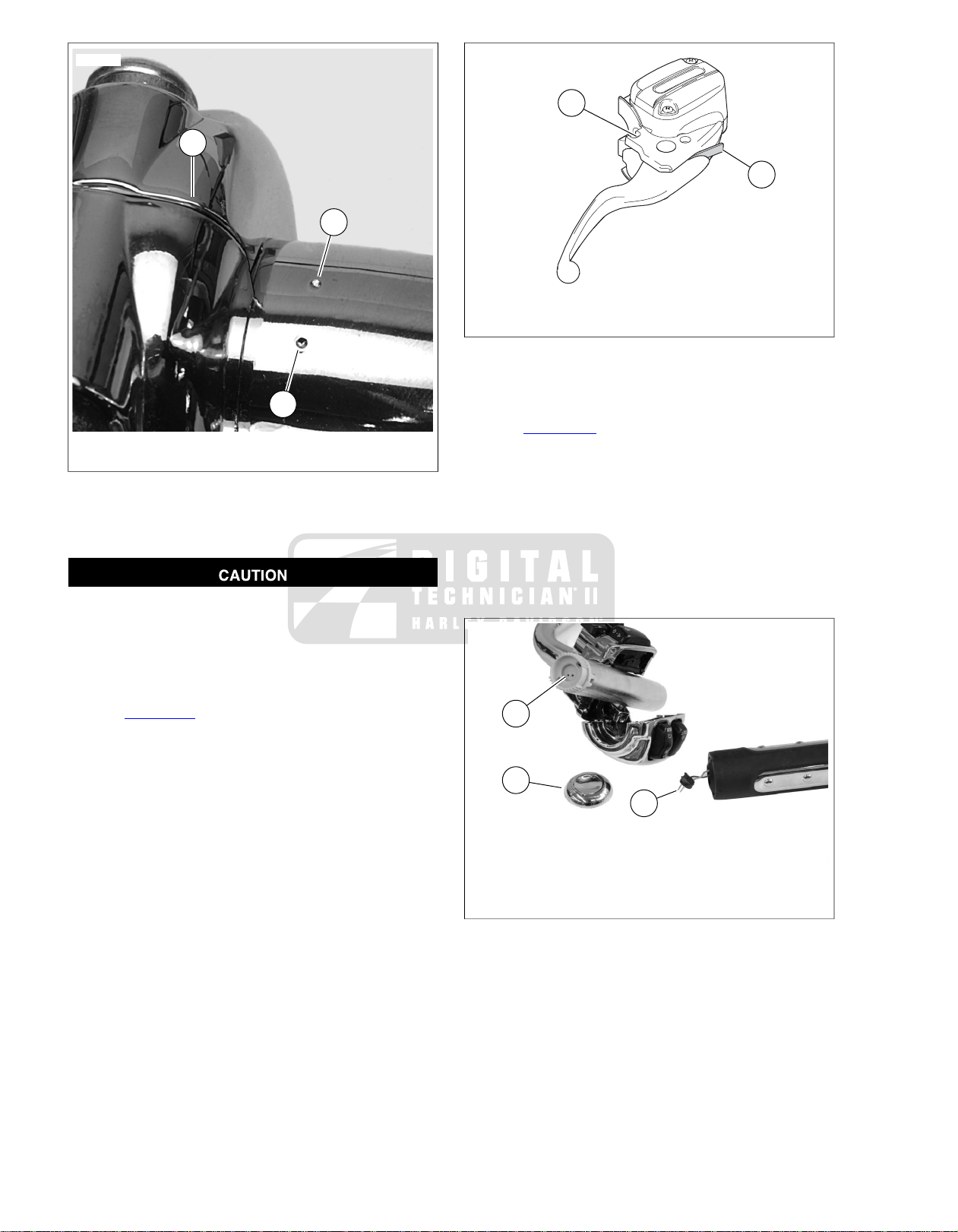
2
2
1
sm03982
2
1
sm04667
3
1
2
sm04677
1. Clamping surface
2. Range marks
Figure 2-34. LH Control Assembly to Handlebars
Remove Right Handgrip
Do not remove or install the master cylinder assembly
without first positioning a 5/32-inch (4 mm) thick insert
between the brake lever and lever bracket. Removing or
installing the master cylinder assembly without the insert
in place may result in damage to the rubber boot and
plunger on the front stoplight switch. (00324a)
1. See Figure 2-35. Squeeze front brake lever and insert a
5/32 in. (4 mm) thick cardboard insert between front brake
lever and lever bracket.
2. Remove master cylinder and front brake le ver and suspend
out of the way.
3. Remove fasteners securing right switch control housing
halves to handlebar.
NOTE
To remove the throttle handgrip, a slight tug may necessary.
4. Separate switch housings and pull handgrip off end of
handlebar.
1. Groove
2. 5/32 in. (4 mm) thick cardboard insert
Figure 2-35. Cardboard Insert
Install Right Handgrip
1. See Figure 2-36. Ensure twist grip sensor is properly
installed in end of handlebar.
2. Remove end cap (1) from handgrip.
3. Press handgrip onto twist grip sensor and handlebar until
it is seated. Rotate handgrip to ensure proper engagement.
4. Using needle nose pliers, reach through the hole in the
end of the handgrip and insert prongs of connector (2) into
connector holes (3) located in end of twist grip sensor.
Install end cap (1).
1. End cap
2. Heated grip connector
3. Recepticle in TGS
Figure 2-36. Right Handgrip Heater Connector
2-22 2008 FLHTCUSE3 Service: Chassis
Page 47
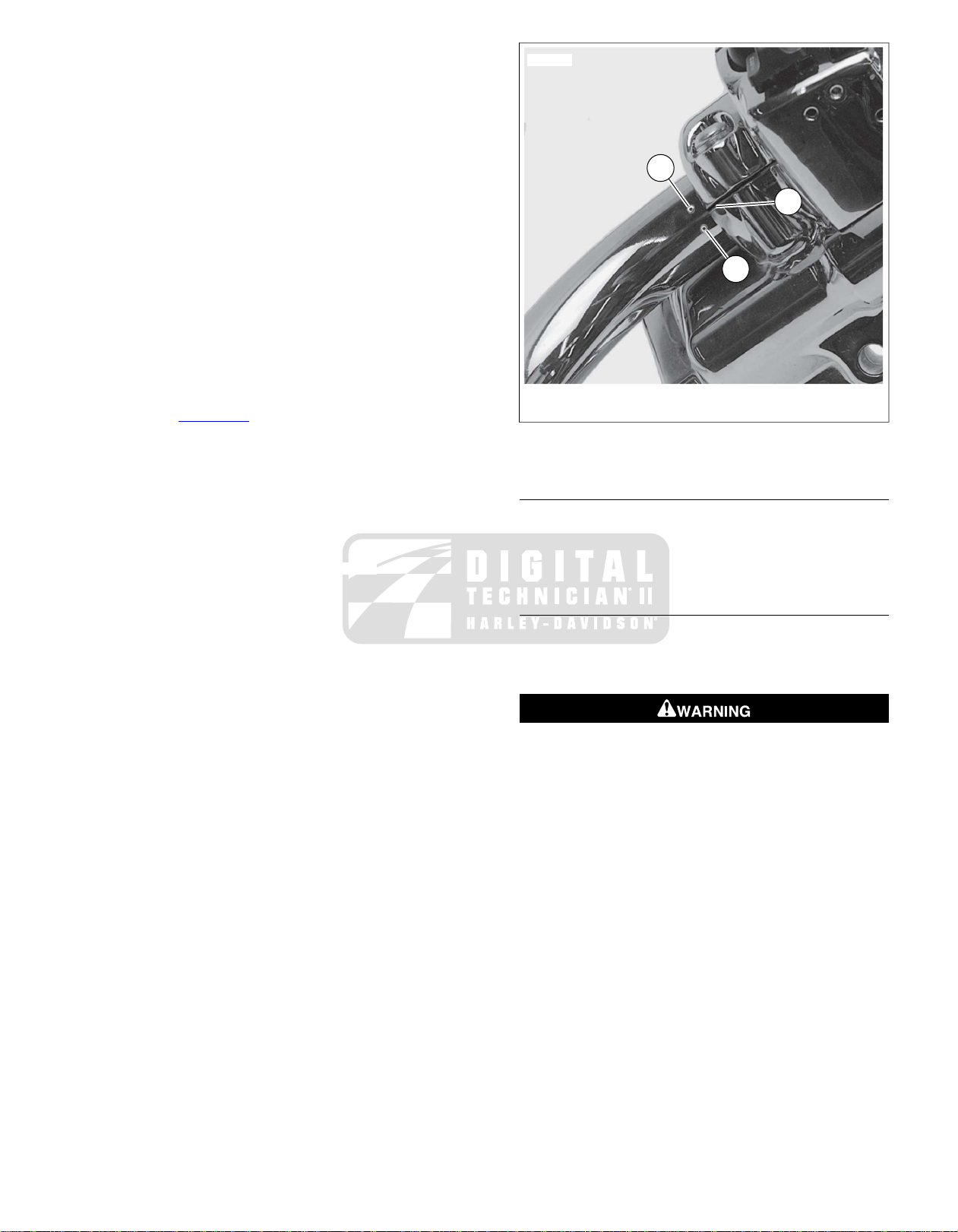
5. Assemble right switch control housing halves:
1
2
2
sm04496
a. Position upper switch housing so wire conduit wraps
around outside of handlebar and sets in clearance at
bottom of handlebar.
b. Verify that wires will not be pinched when fasteners
are tightened.
c. Install switch housing fasteners finger tight.
d. Verify that throttle works freely.
6. Loosely install front brake master cylinder and reservoir:
a. Engage tab on switch with notch at top of brake le v er
bracket.
b. Alternately tighten housing and bracket fasteners until
all components fit and wires route without interference. Fasteners should only be snug.
NOTE
Control wiring is routed inside the handlebar and may be
pinched or cut if controls are rotated too far.
7. See Figure 2-37. Rotate brake master cylinder assembly
slightly for most comfortable riding position. Make sure
assembly is positioned so that clamp mating surface (1)
is located in area between range marks (2).
8. Tighten master cylinder clamps beginning with top fastener
to 72-84 in-lbs (8.1-9.5 Nm). The gap, if any must be at
clearance flat on handlebar.
9. Tighten switch housing fasteners beginning with bottom
fastener to 35-45 in-lbs (4.0-5.1 Nm). Rear gap, if any,
should be tighter.
10. Squeeze front brake lever and remove cardboard insert.
Check operation of brake light while squeezing brak e lev er.
11. Verify throttle operates freely.
1. Clamping surface
2. Range marks
Figure 2-37. RH Assembly to Handlebar
MATING CONNECTORS
1. Mate heated handgrip power connector [189] housings
and interconnect harness connector [206] housings.
2. Install handgrip interconnect harness cable strap and
harness bundle cable strap.
RETURNING TO SERVICE
1. Install fairing cap and outer fairing. See FAIRING CAP in
Touring Models Service Manual.
2. Install maxi-fuse, left sidecover and left saddlebag.
Be sure that all lights and switches operate properly bef ore
operating motorcycle. Low visibility of rider can result in
death or serious injury. (00316a)
3. Test heated handgrips and handlebar switches for operation.
2008 FLHTCUSE3 Service: Chassis 2-23
Page 48
GENERAL
2.9CLUTCH MASTER CYLINDER AND RESER V OIR
The clutch is hydraulically actuated. Squeezing the clutch hand
lever causes the clutch master cylinder to apply pressure via
the clutch fluid in the clutch line to the secondary clutch actuator
mounted in the clutch release cover. The secondary clutch
actuator piston extends and contacts the clutch release bearing
which disengages the clutch.
A bleeder valve at the secondary clutch actuator is used to
bleed air from the clutch line. D.O.T. 4 HYDRAULIC BRAKE
FLUID (Part No. 99953-99A) is used in the clutch system and
is referred to as clutch fluid in this manual.
Check the clutch fluid level in the clutch fluid reservoir on left
handlebar. If the sight glass is dark, the fluid level in the
reservoir is above the sight glass prism and the reservoir is
full. If the sight glass appears clear, the fluid lev el is below the
sight glass prism and the fluid level should be check ed. Clutch
fluid should be level with the internal shelf marked FILL LEVEL
with the motorcycle upright and the gasket surface level.
D.O.T. 4 hydraulic brake fluid is used in the hydraulic
clutch. Do not use other types of fluids as they are not
compatible and could cause equipment damage. (00353a)
NOTE
Clutch fluid volume in reservoir actually increases with clutch
wear. Do NOT overfill clutch reservoir.
REMOVAL
1. Remove acorn nut, lockwasher and rear view mirror with
washer. Support turn signal bullet housing and bracket.
2. Loosen left handlebar switch housing fasteners.
Do not allow dirt or debris to enter the master cylinder
reservoir . Dirt or debris in the reservoir can cause improper
operation and equipment damage. (00205c)
3. See Figure 2-38. Loosen, but do not remove, fasteners
(1) that secure handlebar clamp to clutch master cylinder/reservoir.
4. Loosen both cover screws (2) to relie ve pressure in master
cylinder/reservoir.
Be sure no clutch fluid gets on tires, wheels or brakes
when draining fluid. Traction can be adversely affected,
which could result in loss of control and death or serious
injury. (00295a)
D.O.T. 4 brake fluid will damage painted and body panel
surfaces it comes in contact with. Alwa ys use caution and
protect surfaces from spills whenever brake work is performed. F ailure to comply can result in cosmetic damage.
(00239b)
• Do not wipe any spilled brake fluid off of finished surf aces.
Always flush the affected components with water (not
soapy).
NOTE
Place a large cup under the banjo fitting. Hydraulic fluid will
begin draining from the reservoir as the banjo bolt is removed.
Avoid leakage. Be sure gaskets, banjo bolt(s) and clutch
line are clean and undamaged before assembly. (00329a)
5. Slowly loosen banjo bolt (9) and allow clutch fluid from
reservoir to drain into cup.
NOTE
Dispose of clutch fluid in accordance with local regulations.
6. Remove banjo bolt (9) and two steel/rubber washers (8).
Discard steel/rubber washers.
NOTE
To prevent the rest of the clutch fluid from draining from the
clutch line and secondary clutch actuator, support the banjo
fitting and clutch fluid line upright. Plug the banjo bolt hole with
a finger to transfer the assembly to a workbench without spilling
clutch fluid.
7. Remove master cylinder clamp screws and remo ve clutch
master cylinder/reservoir assembly.
Direct contact of D.O.T. 4 brake fluid with eyes can cause
irritation. Avoid eye contact. In case of eye contact flush
with large amounts of water and get medical attention.
Swallowing large amounts of D.O .T . 4 brake fluid can cause
digestive discomfort. If swallowed, obtain medical attention. Use in well ventilated area. KEEP OUT OF REACH OF
CHILDREN. (00240a)
2-24 2008 FLHTCUSE3 Service: Chassis
Page 49
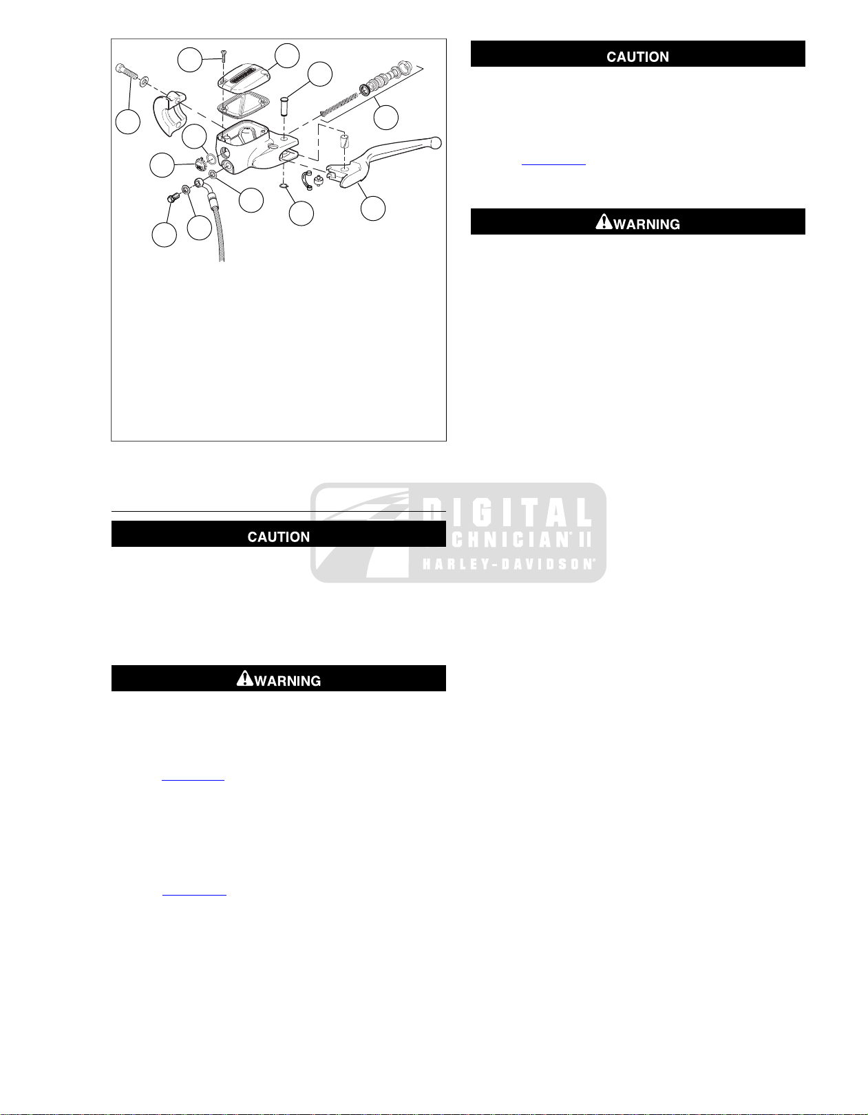
1
2
11
10
3
4
5
8
8
9
7
6
sm04672
1. Clamp screw
2. Cover hold down screws
3. Cover
4. Pivot pin
5. Internal components
6. Clutch hand lever
7. Retaining ring
8. Steel/rubber washers
9. Banjo bolt
10. Sight glass
11. O-ring
Figure 2-38. Clutch Master Cylinder/Reservoir
DISASSEMBLY
Avoid leakage. Prevent damage to piston or piston bore.
Use non-metallic tools when servicing components.
(00529d)
6. Remove cups (5, 7) from piston using a toothpick.
7. See Figure 2-38. If necessary, push the sight glass (10)
into the reservoir to remove. Remove and discard o-ring
(11).
Use denatured alcohol to clean clutch system components.
Do not use mineral-based solvents (such as gasoline or
paint thinner), which will deteriorate rubber parts even
after assembly. Deterioration of these components can
cause clutch failure, which could result in death or serious
injury. (00296a)
8. Wipe the housing with a lint free cloth. With a clean air
supply, blow out drilled passages and bore in the master
cylinder housing.
NOTE
Do not use a wire or sharp instrument to clean drilled passages.
9. Inspect cylinder housing bore for scoring, pitting or corrosion. Also chec k outlet port for damage. Replace housing
if necessary.
10. Inspect the cover, sight glass, and gasket for cuts, tears
or general deterioration.
Do not allow dirt or debris to enter the master cylinder
reservoir . Dirt or debris in the reservoir can cause improper
operation and equipment damage. (00205c)
1. Remove master cylinder cover and gasket.Turn housing
upside down to remove remaining clutch fluid from reservoir.
Wear safety glasses or goggles when removing or
installing retaining rings. Retaining rings can slip from the
pliers and could be propelled with enough for ce to cause
serious eye injury. (00312a)
2. See Figure 2-38. Remo v e retaining ring (7) from piv ot pin
(4).
NOTE
To remove piston spring load from the pivot pin, gently force
the clutch lever toward the piston (as if operating the clutch).
3. Remove pivot pin (4) and clutch lever.
4. See Figure 2-39. Using a toothpick or small screwdriver,
5. Remove piston (2) and spring (4).
gently pry outer edge of piston boot (1) out of piston bore.
2008 FLHTCUSE3 Service: Chassis 2-25
Page 50
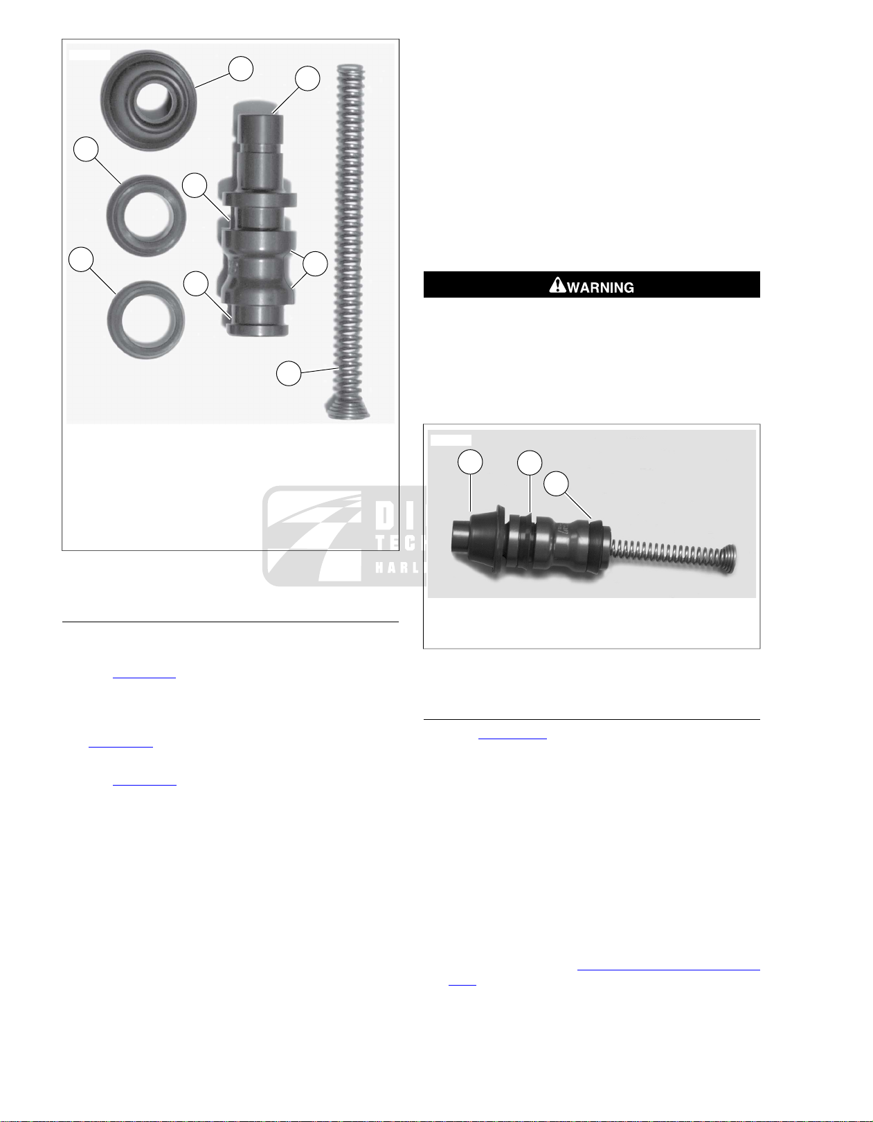
2
4
6
8
7
5
1
3
sm03992
1. Boot
1
2
3
sm03993
2. Piston
3. Shoulder
4. Spring
5. Primary cup
6. Groove - primary cup
7. Secondary cup
8. Groove - secondary cup
Figure 2-39. Clutch Master Cylinder Components
7. Align and install piston assembly into bore. Firmly press
on flat end of piston, compressing spring, until the entire
assembly slides into cylinder bore.
NOTE
When installing the piston sealing boot, be careful not to tear,
perforate or damage the piston sealing boot.
8. Compress piston until it is even with the end of bore. Using
a small dull bladed screwdriver or similar tool, gently work
around sealing edges of boot until entire circumference
of boot is seated in cylinder bore groove.
9. Install cover with new gask et on master cylinder/reservoir.
Install two screws to fasten the cover to reservoir, but do
not tighten.
Wear safety glasses or goggles when removing or
installing retaining rings. Retaining rings can slip from the
pliers and could be propelled with enough for ce to cause
serious eye injury. (00312a)
10. Install clutch hand lever, pivot pin, and a new retaining
ring.
ASSEMBLY
To rebuild clutch master cylinder, use the components found
in the Service Parts Kit.
1. See Figure 2-38. If remo v ed, install sight glass (10) using
a new o-ring (11) lubricated with lubricant provided with
Service Parts Kit.
NOTE
See Figure 2-40. The flared ends of the primar y cup and the
secondary cup must face the spring end of the piston.
2. See Figure 2-40. Using lubricant provided with SERVICE
PARTS KIT, lightly lubricate inside of primary cup (3) and
fit over lip on spring end of piston.
3. Using lubricant provided with SERVICE PARTS KIT , lightly
lubricate inside of secondary cup (2) and fit over the lip
on outboard end of piston.
4. Install boot (1), large sealing ID first, on piston until seal
5. Using lubricant in SERVICE PARTS KIT, thoroughly coat
6. Install spring into piston assembly.
on smaller ID fits snugly into thin groove in piston.
outside diameters of primary and secondary cups and
master cylinder piston bore.
1. Boot installed in piston groove
2. Secondary cup
3. Primary cup
Figure 2-40. Assembled Cups and Piston
INSTALLATION
1. See Figure 2-41. Attach master cylinder/reservoir to
handlebar with handlebar clamp. Orient lever to rider
position, with mating surface joint (1) within range marks
(2) in handlebar. Tighten clamp fasteners to 60-80 in-
lbs (6.8-9.0 Nm).
2. Tighten handlebar switch housing screws to 35-45 in-
lbs (4.0-5.1 Nm).
3. Attach banjo fitting to master cylinder using new
steel/rubber washers.Tighten banjo bolt finger tight.
4. Fill reservoir with D.O.T. 4 HYDRAULIC BRAKE FLUID
(Part No. 99953-99A). Allow fluid to fill clutch line until a
steady flow of clutch fluid flows from bleeder v alve. Finger
tighten bleeder valve.
5. Bleed clutch line. See 1.3 BLEEDING CLUTCH FLUID
LINE.
6. Verify that fluid level in clutch fluid reservoir is at FILL
LEVEL with motorcycle upright and gasket surface level.
2-26 2008 FLHTCUSE3 Service: Chassis
Page 51

NOTE
1
2
2
sm04496
Clutch fluid volume in reservoir actually increases with clutch
wear. Do NOT overfill clutch reservoir.
7. Verify operation by squeezing clutch hand lever.
8. Tighten fasteners as follows:
a. Banjo bolt to 12.5-14.5 ft-lbs (16.9-19.7 Nm).
b. Bleeder screw to 12-15 in-lbs (1.4-1.7 Nm).
c. Reservoir cover screws to 6-8 in-lbs (0.7-0.9 Nm).
9. Install rear view mirror and turn signals with bracket. See
8.5 FRONT TURN SIGNALS.
Be sure that all lights and switches operate properly bef ore
operating motorcycle. Low visibility of rider can result in
death or serious injury. (00316a)
10. Test ride motorcycle.
1. Clamping surface
2. Range marks
Figure 2-41. RH Assembly to Handlebar
2008 FLHTCUSE3 Service: Chassis 2-27
Page 52
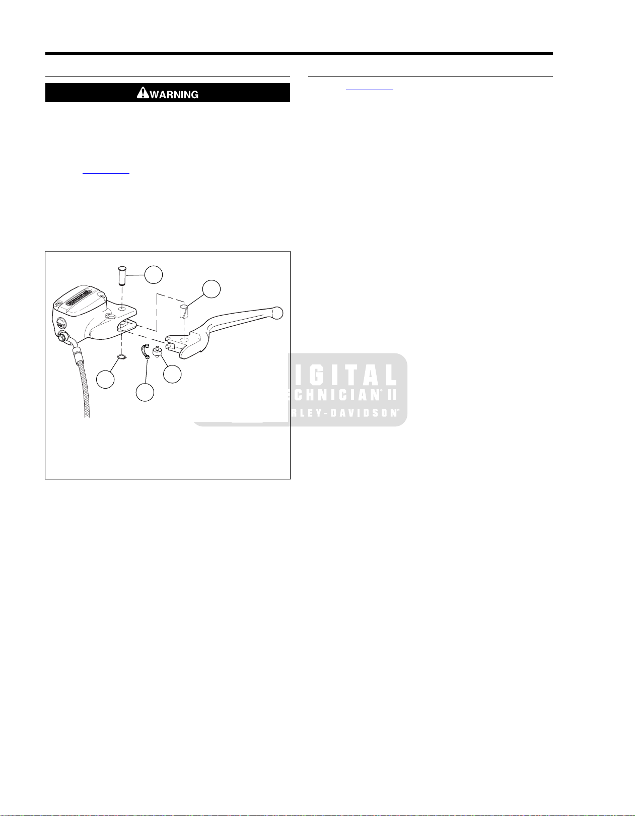
2.10CLUTCH HAND LEVER
4
2
5
1
3
sm04674
REMOVAL
T o prevent accidental vehic le start-up, whic h could cause
death or serious injury, remove main fuse before proceeding. (00251b)
1. Remove the maxi-fuse.
2. See Figure 2-42. Remove the retaining ring (1) from the
pivot pin (2).
3. Remove pivot pin and lever.
4. Disassemble roller pin (3) and bushing cups (4).
5. Remove pivot bushing (5).
INSTALLATION
1. See Figure 2-42. Slide bushing cups onto pins of roller
(3).
NOTE
Be careful when handling the bushing cups.The bushing cups
are hard plastic and easily broken.
2. With connector bow portion of the bushing cups parallel
with groove in clutch handle, snap roller pin and bushing
cups into clutch lever roller groove. Roller/bushing
assembly will install with a snap and will be held securely.
3. Lightly grease pivot bushing (5) and install into clutch hand
lever pivot hole. Position bushing until it is flush with both
sides of lever.
NOTE
If the clutch master cylinder/reservoir is full of clutch fluid under
pressure, it may be necessary to apply force to the hydraulic
piston in order to align the clutch hand lever and to allow the
pivot pin to be inserted.
4. Orient clutch lever in lever mounting bracket. Insert pivot
pin from top.
5. Install new retaining ring on pivot pin.
6. Install maxi-fuse.
7. Verify clutch lever operation.
1. Retaining ring
2. Pivot pin
3. Roller pin
4. Bushing cups
5. Pivot bushing
Figure 2-42. Clutch Hand Lever
2-28 2008 FLHTCUSE3 Service: Chassis
Page 53
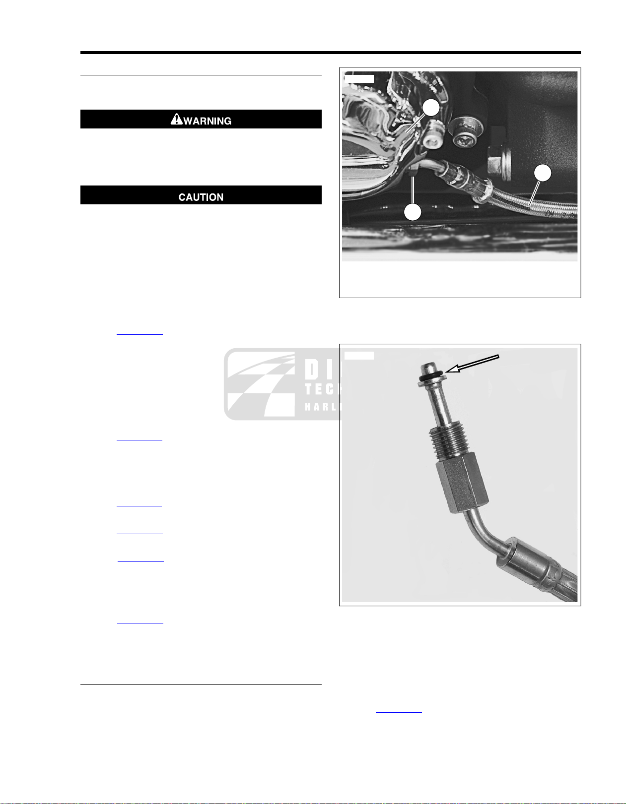
1
3
2
sm03996
sm03997
REMOVAL
1. Remove outer fairing. See Touring Models Service Manual
for procedure.
Be sure no clutch fluid gets on tires, wheels or brakes
when adding fluid. Traction can be adversely affected,
which could result in loss of control and death or serious
injury. (00294a)
D.O.T. 4 brake fluid will damage painted and body panel
surfaces it comes in contact with. Alwa ys use caution and
protect surfaces from spills whenever brake work is performed. F ailure to comply can result in cosmetic damage.
(00239b)
• Do not wipe any spilled brake fluid off from finished surfaces. Always flush the affected components with water
(not soapy).
2. Loosen the clutch master cylinder/reservoir cover.
3. See Figure 2-43. Place a suitable container under clutch
release cover (3).
4. Loosen flare nut (1) and allow clutch fluid to drain.
5. Remove flare nut from clutch release cover.
6. Drain clutch fluid line.
NOTE
Dispose of clutch fluid in accordance with local regulations.
7. See Figure 2-44. Remove and discard o-ring.
NOTE
Clutch fluid line o-ring may stick to inside of clutch release
cover. Use a non-metallic pick to remove old o-ring and other
debris.
8. See Figure 2-45. Remo v e banjo bolt (5) and two w ashers
(4). Discard washers.
9. See Figure 2-46. Carefully pull banjo fitting end of clutch
fluid line out through inner fairing grommet.
10. See Figure 2-47. Loosen clamps along right side frame
down tube.
a. Top clamp is secured with engine guard bolt.
b. Bottom clamp is secured to crossbrace.
11. See Figure 2-48. Cut cable ties securing clutch fluid line
at original locations on inner fairing bracket and behind
cam cover.
12. Remove clutch fluid line.
INSTALLATION
1. Route clutch fluid line through fairing grommet retracing
original path of line.
2. Loosely install banjo bolt and new washers.
2.11CLUTCH FLUID LINE
1. Flare nut
2. Clutch fluid line
3. Clutch release cover
Figure 2-43. Clutch Flare Nut and Fluid Line
Figure 2-44. Clutch Fluid Line O-ring
3. Route clutch fluid line down right side frame tube, through
clamps, under cam cover and up to clutch release cover.
4. Install new o-ring on end of clutch fluid line.
5. Install flare nut to clutch release cover and finger tighten.
6. See Figure 2-48. Secure clutch fluid line at original locations on inner fairing bracket, and behind cam co ver using
cable ties.
2008 FLHTCUSE3 Service: Chassis 2-29
Page 54

7. See Figure 2-47.Tighten right side frame tube clamps.
2
3
1
4
5
sm04675
sm03999
sm04000
sm04001
a. Engine guard bolt to 15-20 ft-lbs (21-27 Nm).
b. Clutch fluid line clamp bolt to 96-120 in-lbs (11-13
Nm).
8. Replace the clutch fluid and bleed the clutch fluid line. See
1.3 BLEEDING CLUTCH FLUID LINE.
1. Clutch lever
2. Clutch master cylinder/reservoir
3. Clutch fluid line assembly
4. Banjo bolt washer (2)
5. Banjo bolt
Figure 2-45. Clutch Master Cylinder Assembly and Fluid
Line
Figure 2-47. Clamp Locations on Frame Down Tube
Figure 2-46. Clutch Fluid Line Inner Fairing Grommet
2-30 2008 FLHTCUSE3 Service: Chassis
Figure 2-48. Cable Tie Location Around Clutch Fluid Line
Page 55
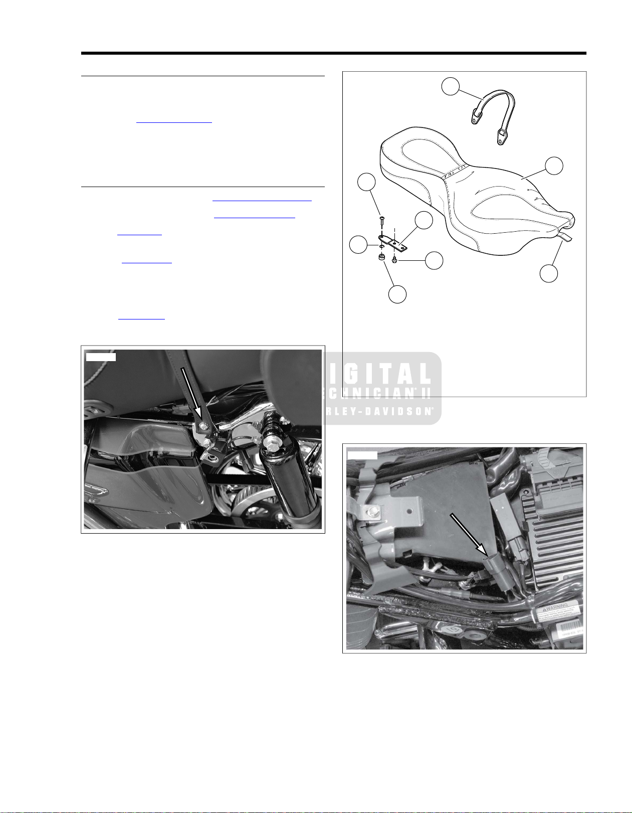
GENERAL
sm04002
7
8
5
3
1
4
6
2
sm04003
sm04121
The FLHTCUSE3 is equipped with a heated seat. Individual
controls, mounted on left side of seat, provide warmth to the
rider seat and passenger pillion separately. For electrical diagnostics, see 8.6 HEATED SEAT.
NOTE
Heater elements are not serviceable. If heater fails, seat must
be replaced.
REMOVAL
1. Remove rider backrest. See 2.13 RIDER BACKREST.
2. Remove left saddlebag. See 2.15 SADDLEBAGS.
3. See Figure 2-49. Remo ve fastener with flat w asher holding
one side of passenger grabstrap.
4. See Figure 2-50. Remove screw (3) securing seat
mounting bracket (5) to fender.
5. Slide seat backward to free tongue (4) on bottom front of
seat from slot in frame backbone.
6. See Figure 2-50. Unplug seat heater harness connector
[191]. Remove seat.
2.12SEAT
1. Passenger grab strap
2. Seat
3. Screw
4. Tongue
5. Mounting bracket
6. Retention nut
7. Retention washer
8. Screw (2)
Figure 2-50. Seat Components
Figure 2-49. Passenger Grab Strap Fastener
Figure 2-51. Heated Seat Connector [191]
2008 FLHTCUSE3 Service: Chassis 2-31
Page 56
CLEANING AND INSPECTION
Do not use bleach or detergents containing bleach on
saddlebags, seats, tank panels or painted surfaces. Doing
so can result in equipment damage. (00229a)
• Do not use ordinary soap to clean leather . It could dry
or remove the oils from the leather.
• Use ONL Y a good quality saddle soap to c lean leather.
Be sure to rinse saddle soap off thoroughly before
treating leather.
• Never try to dry leather quickly , using artificial means.
Always let leather dry naturally at room temperature.
NOTE
Harley-Davidson Leather Dressing (Part No. 98261-91V) has
been tested and approved for materials used in FLHTCUSE3
seats.
1. Inspect seat, wiring harness and connector for wear or
damage.
2. Clean underside of pillion and seat. Clean fender and
frame mounting surfaces.
INSTALLATION
1. See Figure 2-51. Set seat on frame. Plug in seat heater
harness connector [191]. Tuck harness down into frame
cavity. Make sure harness will not be pinched between
seat pan and vehicle frame.
2. See Figure 2-50. Slide seat forward until tongue (4)
engages slot in frame backbone.
3. Push seat forward until retention nut (6) in fender is
centered in hole of mounting bracket (5). Install screw (3)
and tighten securely.
After installing seat, pull upward on seat to be sure it is
locked in position. While riding, a loose seat can shift
causing loss of control, which could result in death or
serious injury. (00070b)
4. Pull up on seat to verify that it is properly secured.
5. See Figure 2-49. Install passenger grabstrap to left
saddlebag mounting bracket.
6. Install left saddlebag.
7. Install rider backrest.
2-32 2008 FLHTCUSE3 Service: Chassis
Page 57
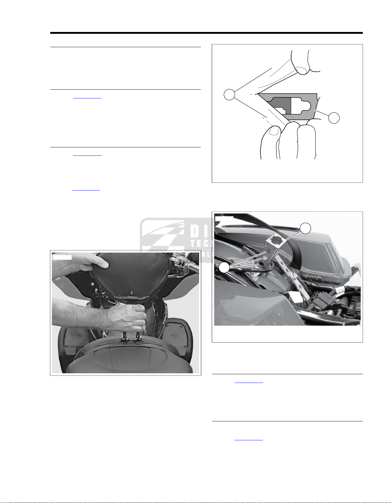
GENERAL
sm04005
1
2
sm04006
1
2
sm04007
The FLHTCUSE3 is equipped with a removable rider backrest.
It is adjustable vertically, front to rear and has an adjustable
tilt angle.The backrest is spring loaded to assist the passenger
in mounting and dismounting the vehicle.
REMOVAL
1. See Figure 2-52. Spread the seat co vering at the base of
the backrest to expose the two spring loaded support arms.
2. Squeeze together the spring loaded support arms.
3. Pull upward to remove the backrest from the mounting
bracket.
INSTALLATION
1. See Figure 2-53. Spread the seat covering (1) to expose
the backrest mounting bracket (2).
2. Squeeze together the two spring loaded support arms on
the backrest.
3. See Figure 2-54. Insert the support arms into the mounting
bracket (1).
Vertical Adjustment: For rider posture, mo ve the backrest
up or down to select one of the three sets of vertical
adjustment holes (2).
4. Release to lock the backrest in the bracket.
5. Test to assure the backrest is secured into the bracket.
2.13RIDER BACKREST
1. Seat covering
2. Backrest mounting bracket
Figure 2-53. Mounting Bracket Through Seat
1. Backrest mounting bracket
2. Vertical adjustment holes
Figure 2-54. Backrest Mounting Bracket
ADJUSTING TILT ANGLE
Figure 2-52. Remove/Install Backrest
1. See Figure 2-55. Insert a 3/16 inch Allen wrench through
the tilt angle adjustment access hole.
2. Engage the Allen screw and tighten to tilt the backrest
forward, or loosen to tilt the backrest backward.
ADJUSTING FRONT TO REAR
1. Remove backrest and seat.
2. See Figure 2-56. Loosen, b ut do not remov e , scre w (3) at
base of support strap.
2008 FLHTCUSE3 Service: Chassis 2-33
Page 58

3. Remove nut (5) and screw (4). Pivot support strap (2) out
sm04008
1
3
2
5
6
4
sm04009
of the way.
4. Remove nuts (6) and lift mounting brac ket (1) off threaded
studs.
5. With the large nylon washers in place, reposition bracket
in selected pair of horizontal adjustment holes (7).
6. Install nuts and tighten to 60-96 in-lbs (6.8-10.8 Nm).
7. Pivot support strap back into position, line up attachment
holes, and install screw and nut. Tighten to 11-15 ftlbs (15-20 Nm).
8. Finally , tighten support strap fastener to 60-96 in-lbs (6.8-
10.8 Nm).
After installing seat, pull upward on seat to be sure it is
locked in position. While riding, a loose seat can shift
causing loss of control, which could result in death or
serious injury. (00070b)
9. Install seat.
10. Make sure backrest fits properly and can be installed correctly in mounting holes in backrest mounting bracket.
1. Backrest mounting bracket
2. Support strap
3. Screw
4. Nut
5. Nut (2)
6. Horizontal adjustment holes
Figure 2-56. Backrest Mounting Bracket
Figure 2-55. Adjust Rider Backrest Tilt Angle
2-34 2008 FLHTCUSE3 Service: Chassis
Page 59

5
8
7
6
1
3
2
4
sm04010
1
2
sm04011
REMOVAL
NOTE
The following procedure is best performed with the aid of an
assistant.
1. Remove maxi-fuse.
2. Remove both saddlebags. See 2.15 SADDLEBAGS.
3. Remove seat. See 2.12 SEAT.
4. Open Tour-Pak and remove bottom liner.
5. See Figure 2-57. Separate interior connections:
a. Tour-Pak power lock connector [213T] (1).
b. One-place CB antenna connector [104] (2).
c. Harness clip (3).
d. AM/FM/WB antenna cable connector [29] (5).
e. Harness clip (6).
f. Interior light harness connector [190] (7).
6. Feed CB antenna harness and connector [104] through
right rear exit hole (4).
7. Remove split grommet (8) and feed AM/FM/WB antenna
cable and wiring harness through exit hole.
8. Slide a clean shop towel between amplifier and fender to
protect rear fender finish.
9. See Figure 2-58. Make note of which set of five locating
holes are used to mount Tour-Pak.
10. See Figure 2-59. Remove four locknuts with nylon caps
(1). Remo ve w ashers (2), spacers (5), bolts (3), and large
washers (4).
11. Lower amplifier and allow to rest on fender.
NOTE
Have an assistant hold Tour-Pak for last step.
12. Remove center-rear locknut (6). Remove washer (8),
antenna ground lead (9), center-rear bolt (7) and spacer
(5).
2.14TOUR-PAK
1. Power lock connector [213T]
2. One-place CB antenna connector [104]
3. Clip
4. Right rear exit hole
5. AM/FM/WB antenna cable connector [29]
6. Clip
7. Tour-Pak light connector [190]
8. Split grommet and exit hole
Figure 2-57. Interior Connections (Power Lock Removed)
1. Forward location holes
2. Rearward location holes
Figure 2-58.Tour-Pak Locating Holes
2008 FLHTCUSE3 Service: Chassis 2-35
Page 60

3
8
11
5
7
6
10
2
1
9
4
sm04012
1. Locknut (4)
2. Washer (4)
3. Bolt (4)
4. Large washer (2)
5. Spacer (5)
6. Center-rear locknut
7. Center-rear bolt
8. Washer
9. Antenna ground lead
10. License plate bracket
11. Amplifier
Figure 2-59.Tour-Pak/Amplifier Mounting
3. See Figure 2-60. F rom inside of Tour-Pak, install right rear
bolt (1) and large O.D. flat washer (2) through bottom (3)
of Tour-Pak, hole in top support tube, spacer (4), amplifier
flange (5) and hole in license plate bracket (6).
4. Install flat washer (7) and locknut (8) with cap on right rear
bolt and tighten finger-tight.
NOTE
This fastener will keep Tour-Pak in position while remaining
fasteners are installed.
5. See Figure 2-59. Install center-rear bolt (7) from bottom,
through spacer, top support tube, Tour-Pak, antenna
ground lead ring terminal, and flat washer. Secure with
center-rear lock nut (6) and finger-tighten.
6. Position amplifier so that rear corners of mounting flange
are between spacers and license plate bracket.
7. In the same manner, install remaining bolts, washers,
spacers and nuts. Ensure front fasteners also secure the
front of the amplifier (11).
8. See Figure 2-61. In sequence sho wn, tighten fasteners to
96-108 in-lbs (10.9-12.2 Nm).
9. Feed Tour-Pak lighting harness, power lock harness and
AM/FM/WB antenna cable up through hole in bottom left
front corner and install split grommet in hole.
10. Route antenna cable through clip in bottom of Tour-Pak.
11. Feed CB antenna cable up through hole in bottom right
front corner of Tour-Pak and install split grommet in hole.
12. Install CB antenna cable in its clips on bottom right side
of Tour-Pak.
13. Verify that AM/FM/WB antenna ground strap is securely
fastened to base plate in Tour-Pak with center-rear
mounting screw.
14. Mate interior connectors:
a. Tour-Pak power lock connector [213T].
b. One-place CB antenna connector [104].
c. AM/FM/WB antenna cable connector [29] (finger
tight).
d. Interior light harness connector [190].
15. Install molded Tour-Pak liner and close Tour-Pak lid.
INSTALLATION
1. Place two spacers, one on each side, between top support
tube and license plate bracket. Line up holes in spacers
with rear holes in top support tube.
See Figure 2-58. For passenger comfort, the Tour-Pak can be
adjusted forward or rearward. Select the location holes for the
position selected.
2. Set Tour-Pak in place on top support tube.
Have an assistant hold Tour-Pak in position.
NOTE
NOTE
After installing seat, pull upward on seat to be sure it is
locked in position. While riding, a loose seat can shift
causing loss of control, which could result in death or
serious injury. (00070b)
16. Install maxi-fuse, saddlebags, and seat.
2-36 2008 FLHTCUSE3 Service: Chassis
Page 61
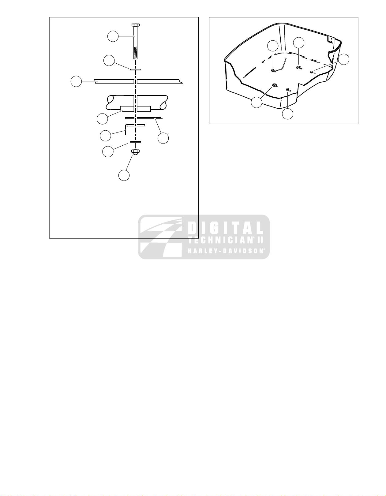
1
6
2
4
8
5
3
7
sm04014
1. Bolt
3
2
4
1
5
sm04015
2. Washer
3. Tour-Pak bottom
4. Spacer
5. Amplifier bracket
6. License plate bracket
7. Washer
8. Locknut
Figure 2-60. Fastener Stack
Figure 2-61.Tour-Pak Torque Sequence
2008 FLHTCUSE3 Service: Chassis 2-37
Page 62
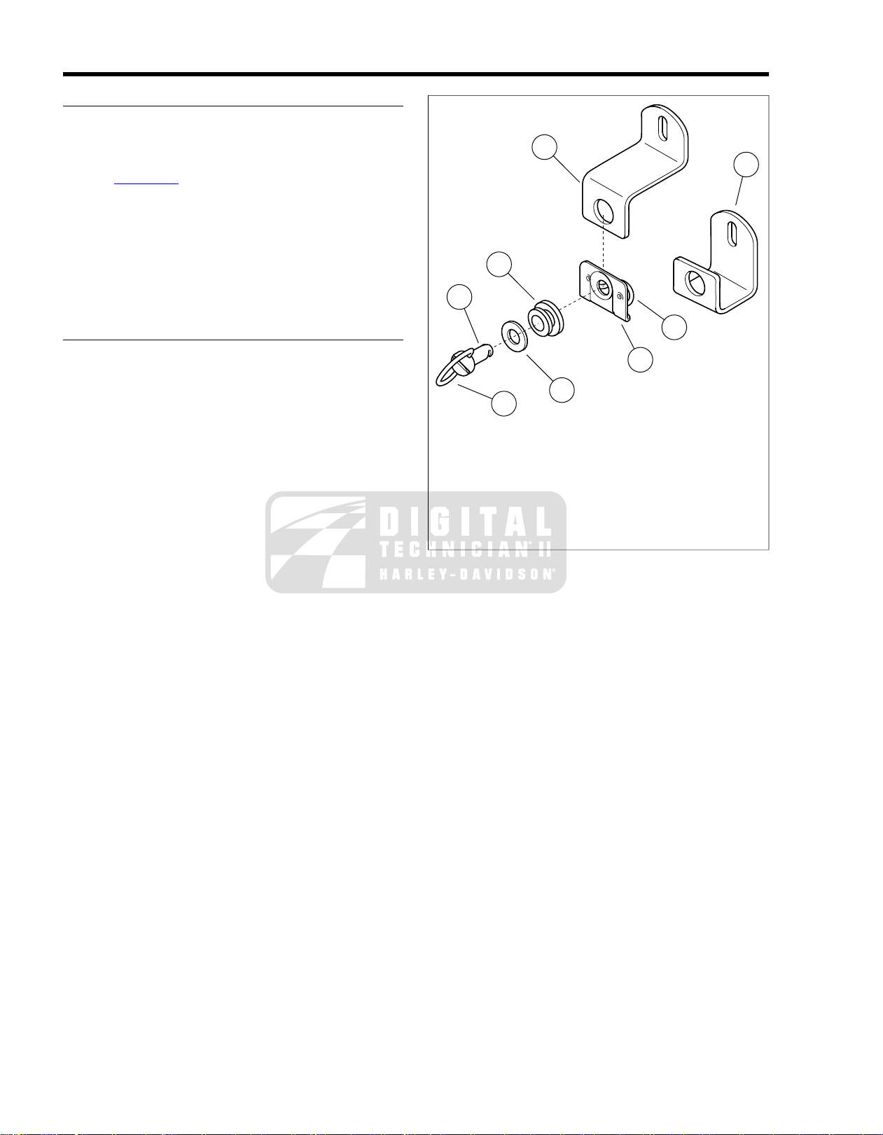
REMOVAL
1
3
5
6
7
8
4
2
sm03538
NOTE
To prevent dropping saddlebags and damaging finish, hold
saddlebag while removing bail head studs.
1. See Figure 2-62. Open saddlebag lids and turn bail head
studs 1/4 turn counterclockwise and remove fasteners and
washers.
NOTE
International models will require a flat bladed screwdriver to
remove the saddlebag fasteners.
2. Tilt saddlebag away from motorcycle and separate the
electrical connector for the power lock.
INSTALLATION
1. Carefully place saddlebag in position on rail.
2. Supporting the saddlebag, mate the power lock connector
housings.
3. Align the bail head studs with the support bracket holes
and push the studs into the bracket while turing 1/4 turn
clockwise.
2.15SADDLEBAGS
1. Bail wire
2. Stud
3. Flat washer
4. Grommet
5. Spring plate
6. Wire form
7. Front bracket
8. Rear bracket
Figure 2-62. Saddlebag Quick-Release Fasteners
2-38 2008 FLHTCUSE3 Service: Chassis
Page 63
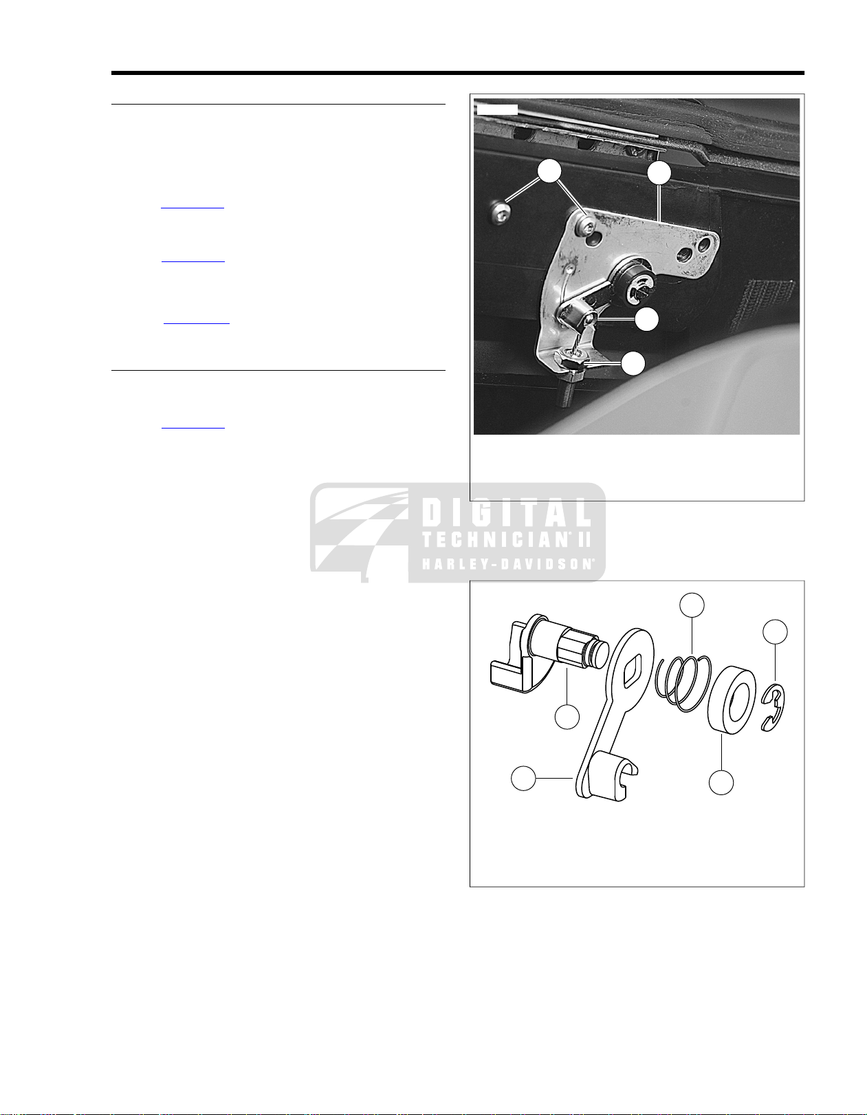
REMOVAL
3
4
2
1
sm04019
1
4
2
3
5
sm04020
1. Remove maxi-fuse.
2. Open saddlebag and lift out felt liner.
3. Remove the two screws from the chec k strap and the latch
cover.
4. See Figure 2-63. Loosen the loc k nut (1) on the cable end
and remove the barrel and cable from the inner cam arm
(2).
5. See Figure 2-64. Remove the e-clip (1).
6. Remove the spacer (2), spring (3), inner cam (4) and outer
cam (5).
7. See Figure 2-63. Remove the two inner screws (3) to
remove the cam plate (4).
INSTALLATION
1. Install the cam plate and finger tighten the two inner
screws.
2. See Figure 2-64. Push the outer cam through the hole in
the saddlebag and cam plate. Align the inner cam to the
square stock of the outer cam.
3. Slide the small end of the spring over the square stock of
the outer cam. Press the spring in place with the spacer.
4. Secure the assembly with the e-clip.
5. Fit the barrel to the cam arm and tighten the lock nut on
the cable end.
6. Tighten the two inner screws to 25 in-lbs (2.8 Nm).
7. Replace the latch cover and tighten the screws to the point
where the tether fabric begins to wrinkle.
8. Replace felt liner.
9. Replace maxi-fuse.
2.16SADDLEBAGS LATCH
1. Lock nut
2. Inner cam arm
3. Inner screws
4. Cam plate
Figure 2-63. Saddle Bag Cam Plate (Co ver and Inner Liner
Removed)
1. E-clip
2. Spacer
3. Spring
4. Inner cam
5. Outer cam
Figure 2-64. Latch Component Alignment
2008 FLHTCUSE3 Service: Chassis 2-39
Page 64

2.17SADDLEBAG SUPPORTS
sm04021
REMOVAL
T o prevent accidental vehic le start-up, whic h could cause
death or serious injury, remove main fuse before proceeding. (00251b)
1. See Touring Models Ser vice Manual and remove the following items:
a. Left and right side covers.
b. Maxi-fuse.
2. Remove saddlebags. See 2.15 SADDLEBAGS.
3. See Figure 2-65 and Figure 2-66. Remove two screws
(14), washers (15) and spacer (4) securing saddlebag filler
strip (3) to vehicle.
4. Remove two screws (18) and lockwashers (19) securing
muffler (16) to saddlebag support (12). Remove muffler
mounting bracket (20) and rubber mount (17).
5. Remove screw (11) and locknut (10) securing front of
saddlebag support to saddlebag guard (22).
6. Remove two screws (13) and locknuts (6) securing rear
of saddlebag support to support bracket (5). Remove
saddlebag support from vehicle.
7. Remove upper front saddlebag bracket (8): screw (7),
washer (2) and bracket.
8. Remove upper rear saddlebag bracket (1): screw (7),
washer (2), bracket, and washer (2).
9. Remove screws (21), support bracket (5) and trim.
10. Repeat above steps on opposite side of vehicle.
5. Loosely attach upper front saddlebag bracket (8): screw
(7), washer (2) and bracket.
6. Loosely attach upper rear saddlebag bracket (1): screw
(7), washer (2), bracket, and washer (2).
7. Temporarily mount saddlebag, position upper saddlebag
mounting brackets lined up with mounting holes in
saddlebag and tighten screws to 15-20 ft-lbs (20.4-27.1
Nm). Remove saddlebag.
8. Install rubber mount (17) onto saddlebag support. Slide
muffler mounting bracket (20) into rubber mount.
9. Attach muffler (16) to muffler mounting bracket with two
screws (18) and lockwashers (19).Tighten to 96-144 in-
lbs (10-9-16.3 Nm).
10. Install saddlebag filler strip (3) with spacer (4), two screws
(14) and washers (15).Tighten to 15-20 ft-lbs (20.4-27.1
Nm).
11. Repeat above steps for opposite side of vehicle.
12. See Touring Models Ser vice Manual and install the following items:
a. Maxi-fuse.
b. Left and right side covers.
c. Saddlebags.
INSTALLATION
1. See Figure 2-66. Position support bracket (5) and trim on
vehicle. Secure with screws (21). Tighten to 15-20 ftlbs (20.4-27.1 Nm).
2. Slide front end of saddlebag support (12) into tube in
saddlebag guard (22). Loosely attach rear of saddlebag
support to support bracket with two scre ws (13) and locknuts (6).
3. Loosely install screw (11) and locknut (10) through
saddlebag guard and saddlebag support.
Figure 2-65. Removing Filler Strip
4. Tighten screws securing rear of saddlebag support to 1520 ft-lbs (20.4-27.1 Nm).Tighten screw securing front of
saddlebag support to 70-100 in-lbs (7.9-11.3 Nm).
2-40 2008 FLHTCUSE3 Service: Chassis
Page 65

4
1
3
7
2
5
17
6
12
20
18
9
2
14
15
14
15
21
13
19
16
22
11
7
9
2
21
10
sm04022
1. Upper rear saddlebag bracket (2)
2. Washer (6)
3. Saddlebag filler strip (2)
4. Spacer (2)
5. Support bracket (2) (right side shown)
6. Locknut (4)
7. Screw (4)
8. Upper front saddlebag bracket (2)
9. Receptacle (4)
10. Locknut (2)
11. Screw (2)
12. Saddlebag support (2) (right side shown)
13. Screw (4)
14. Screw (4)
15. Washer (4)
16. Muffler (2)
17. Rubber mount (2)
18. Screw (4)
19. Lockwasher (4)
20. Muffler mounting bracket (2)
21. Screw (4)
22. Saddlebag guard (2) (right side shown)
Figure 2-66. Saddlebag Support Components
2008 FLHTCUSE3 Service: Chassis 2-41
Page 66

REPLACEMENT
1
2
1
1
sm05061
1. Let motorcycle cool.
2. Loosen three clamps on muffler heat shield (2) and rotate
heat shield to access all three Torx fasteners.
3. See Figure 2-67. Loosen and remove three fasteners (1)
holding muffler end cap.
4. Remove end cap.
5. If necessary, remove and replace clip nut ring and clip
nuts.
6. Install clip nut ring and clip nuts in end cap.
7. Rotate fit to fastener holes in end cap and muffler. Install
and tighten fasteners to 84-108 in-lbs (9.5-12.2 Nm).
8. Return heat shield to original orientation and tighten three
clamps to 20-40 in-lbs (2.3-4.5 Nm).
2.18MUFFLER END CAP
1. Fastener
2. Heat shield
Figure 2-67. Muffler End Cap Fastener Locations
2-42 2008 FLHTCUSE3 Service: Chassis
Page 67

SUBJECT............................................................................................................................PAGE NO.
3.1 SPECIFICATIONS: ENGINE.....................................................................................................3-1
3.2 SERVICE WEAR LIMITS...........................................................................................................3-3
3.3 CYLINDER HEAD.....................................................................................................................3-5
3.4 PISTONS.................................................................................................................................3-16
3.5 BORING AND HONING CYLINDERS.....................................................................................3-17
3.6 CRANKCASE ASSEMBLY......................................................................................................3-20
3.7 OIL COOLER...........................................................................................................................3-23
3.8 OIL COOLER ADAPTER.........................................................................................................3-25
ENGINE
Page 68

NOTES
Page 69
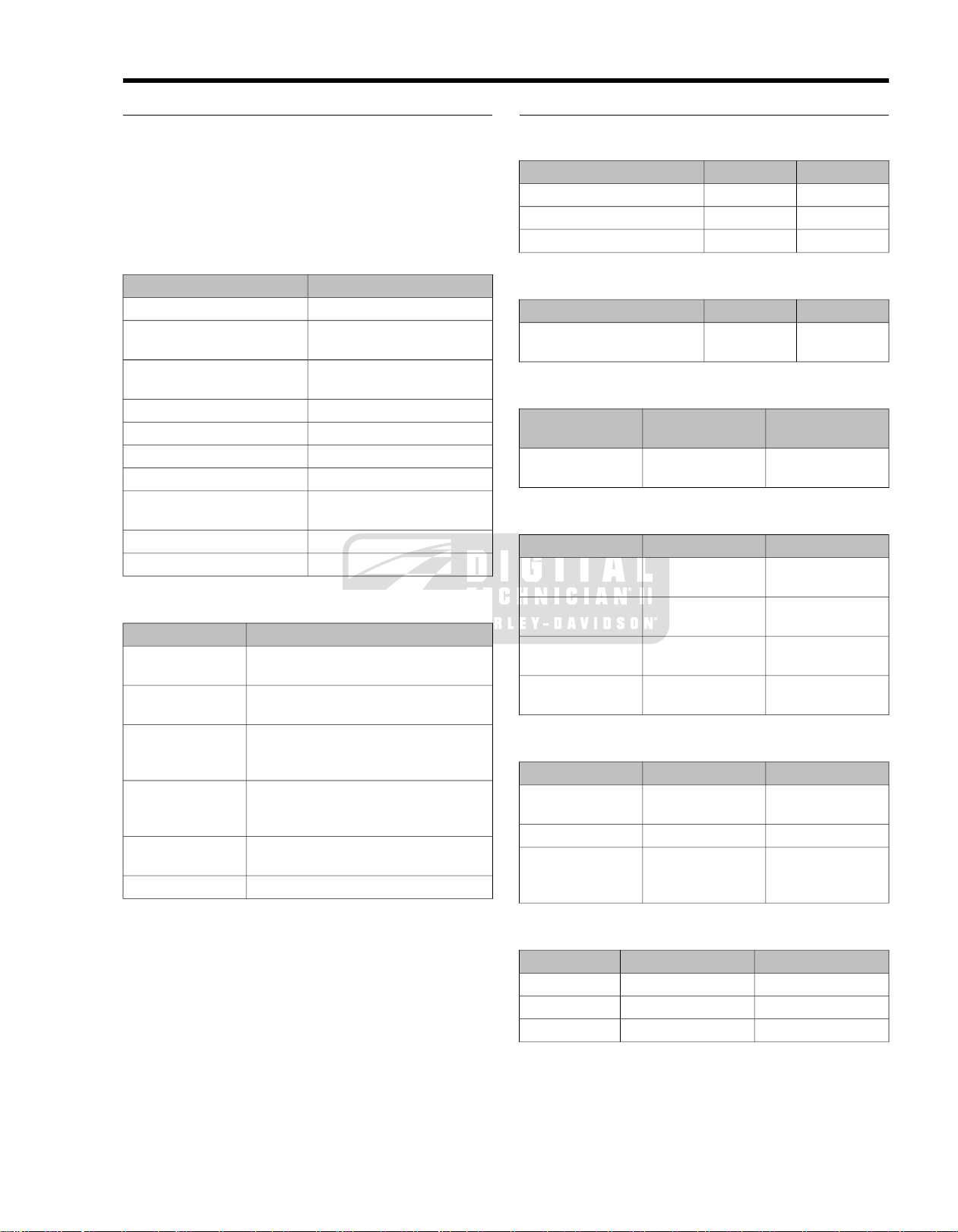
3.1SPECIFICATIONS: ENGINE
GENERAL
NOTE
This chapter provides unique information for models equipped
with Twin-Cam 110 engines. F or models manufactured f or sale
in the country of Japan that are equipped with Twin-Cam 96
engines, see the Service Manual for specifications and service
procedures.
Table 3-1. Engine:TWIN-CAM 110
SPECIFICATIONITEM
2Number of cylinders
Type
Torque
Cam system
with filter
Preferred oil
Pump
Pressure
Filtration
115 ft-lbs (156 Nm) @ 3000
Twin cams, chain driven with
Table 3-2. Oiling System
SPECIFICATIONITEM
4 qt (3.78 L)Oil tank capacity
SYN3 20W50 (Part No. 99824-03/00QT
quart)
Twin gerotor, dual scavenge, crank
mounted and driven, internal oil pump,
dry sump
30-38 psi (207-262 kN/m2) at 2000 RPM
and normal operating temperature of
230° F (110° C)
5 micron media, filtered between pump
and engine
Thermostat controlled oil coolerCooling
4-cycle, 45°
V-Type, air cooled
RPM
4.000 in. (101.60 mm)Bore
4.38 in. (111.13 mm)Stroke
110 cu. in. (1800 cc)Piston displacement (approx.)
9.3:1Compression ratio
hydraulic tensioners
5500 RPMMax. sustained engine speed
1000 RPM ± 50Idle speed
MANUFACTURING TOLERANCES
Table 3-3. Rocker Arms Specifications
MMIN.ROCKER ARMS
0.013-0.0510.0005-0.0020Shaft fit in bushing (loose)
0.08-0.330.003-0.013End clearance
0.051-0.1020.002-0.004Bushing fit in rocker arm (tight)
Table 3-4. Rocker Arm Shaft Specifications
MMIN.ROCKER ARM SHAFTS
0.018-0.0560.0007-0.0022Shaft fit in rocker arm support
plate (loose)
Table 3-5. Hydraulic Lifter Specifications
MMIN.HYDRAULIC
LIFTERS
0.02-0.050.0008-0.0020Fit in crankcase
(loose)
Table 3-6. Cylinder Heads
MMIN.ITEM
0.051-0.0840.0020-0.0033Valv e guide in head
(tight)
0.102-0.1400.004-0.0055Intake valve seat in
head (tight)
0.076-0.1140.003-0.0045Exhaust valve set in
head (tight)
0.0-0.01520.0-0.006Head gasket sur-
face (flatness)
Table 3-7.Valves
MMIN.ITEM
0.028-0.0740.0011-0.0029Fit in guide (intake
and exhaust)
0.86-1.570.034-0.062Seat width
50.55-51.411.990-2.024Stem protrusion
from cylinder head
boss
Table 3-8.Valve Springs Specifications
DIMENSIONPRESSUREITEM
1.800 in (45.7 mm)175 lbs (79 kg)Closed
1.250 in. (31.8 mm)432 lbs (196 kg)Open
2.210 in (56.1 mm)n/aFree length
2008 FLHTCUSE3 Service: Engine 3-1
Page 70
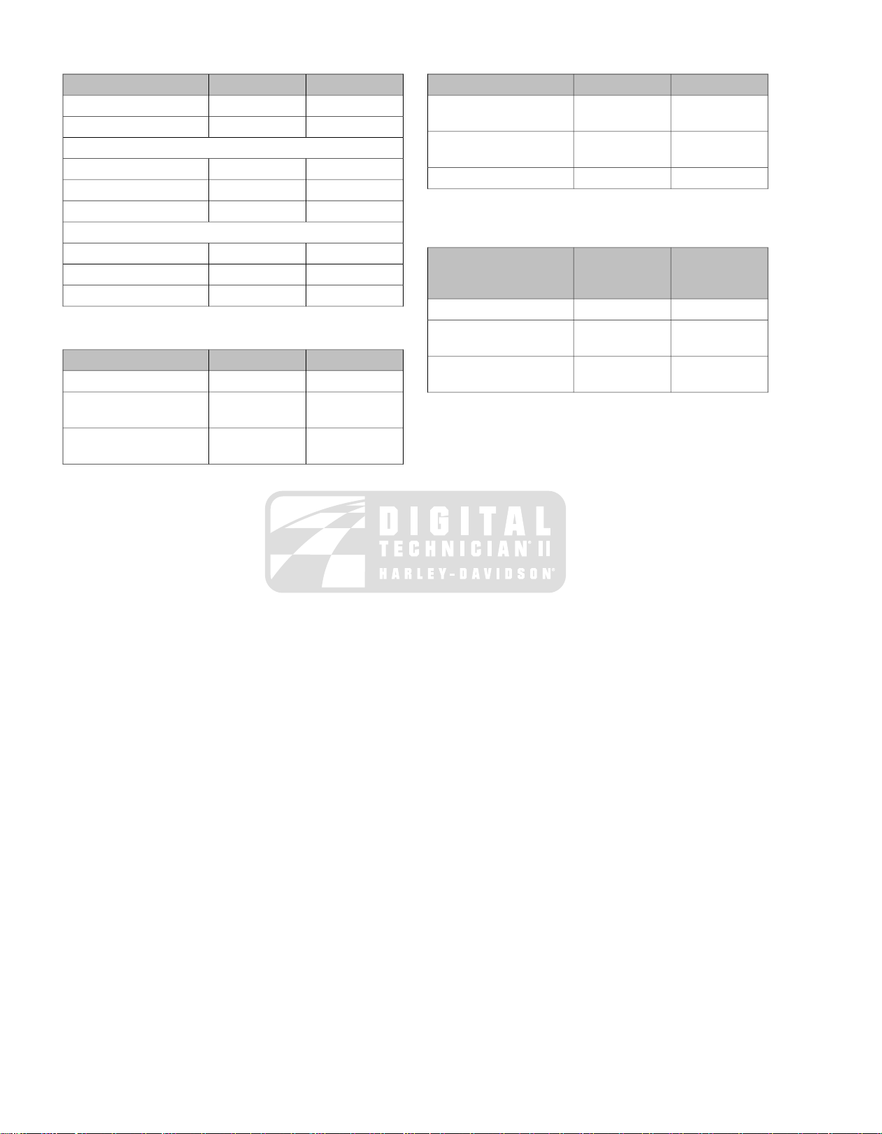
Table 3-9. Pistons
Table 3-11. Flywheels
Ring end gap:
Ring side clearance:
Table 3-10. Connecting Rods
wheels
crankpin (loose)
MMIN.ITEM
0.046-0.0690.0018-0.0027Fit in cylinder
0.013-0.0230.0005-0.0009Piston pin fit (loose)
0.406-0.6100.016-0.024Top compression ring
0.356-0.5590.014-0.0222nd compression ring
0.254-0.7620.010-0.030Oil control ring
0.025-0.0610.00098-0.0024Top compression ring
0.025-0.0610.00098-0.00242nd compression ring
0.051-0.1020.002-0.004Oil control ring
MMIN.ITEM
0.015-0.0300.0006-0.0012Piston pin fit (loose)
0.13-0.380.005-0.015Side play between fly-
0.0102-0.04320.0004-0.0017Connecting rod to
in case)
truing stand)
Table 3-12. Crankshaft/Sprocket Shaft Bearing
Specifications
SHAFT/SPROCKET
SHAFT BEARINGS
(tight)
crankshaft (tight)
MMIN.ITEM
0.0-0.2540.000-0.010Runout (shaft measured
0.0-0.1020.000-0.004Runout (measured in
0.076-0.2540.003-0.010End play
MMIN.CRANK-
0.005-0.0380.0002-0.0015Roller bearing fit (loose)
0.097-0.1370.0038-0.0054Bearing fit in crankcase
0.010-0.0360.0004-0.0014Bearing inner race on
3-2 2008 FLHTCUSE3 Service: Engine
Page 71
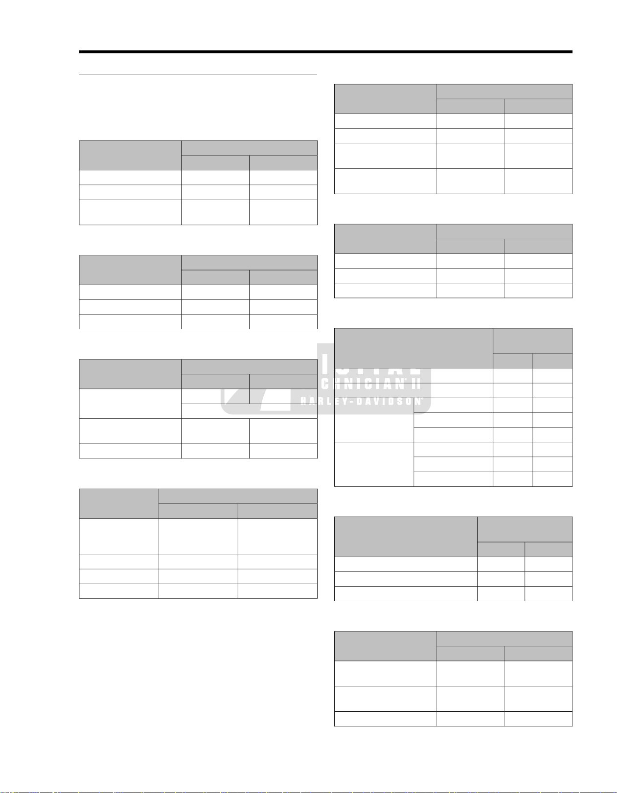
3.2SERVICE WEAR LIMITS
GENERAL
Wear limits can be used as a guide when deciding whether to
reuse engine parts. Replace used parts whenever the f ollowing
wear limits are exceeded.
Table 3-13. Rocker Arm/Rocker Arm Shaft
REPLACE IF WEAR EXCEEDSROCKER ARM/ROCKER
ARM SHAFT
support (loose)
Table 3-14. Hydraulic Lifters
Table 3-15. Cam Support Plate
Crankshaft bushing maximum ID
Table 3-16. Cylinder Heads
REPLACE IF WEAR EXCEEDSITEM
REPLACE IFCAM SUPPORT PLATE
1/2 thickness of shoe
More than
0.8545
MMIN.
0.0890.0035Shaft fit in bushing (loose)
0.6350.025End clearance
0.0890.0035Shaft fit in rocker arm
MMIN.
0.080.003Fit in crankcase
0.0380.0015Roller fit
0.380.015Roller end clearance
MMIN.
More than 2.29More than 0.090Cam chain tensioner shoe
More than
21.704
27.9981.1023Camshaft bore
Table 3-17. Cylinders
O-ring surfaces: top
O-ring surfaces: base
Table 3-18. Cylinder Bore
ITEM
REPLACE IF WEAR EXCEEDSITEM
MMIN.
0.0510.002Taper
0.0510.002Out of round
0.1520.006Warpage of gasket or
0.1020.004Warpage of gasket or
REPLACE IF WEAR EXCEEDSITEM
MMIN.
101.654.002Standard
101.784.0070.005 in. oversize
101.904.0120.010 in. oversize
Table 3-19. Pistons
REPLACE IF
WEAR EXCEEDS
MMIN.
0.0760.003Fit in cylinder (loose)
0.0230.0009Piston pin fit (loose)
0.8640.034Top compressionRing end gap
0.8130.0322nd compression
0.7620.030Oil control ring rails
0.0810.0032Top compressionRing side clearance
0.0810.00322nd compression
0.1020.004Oil control ring rails
(intake and
exhaust)
REPLACE IFITEM
MMIN.
Less than 0.051Less than 0.002Valve guide (tight)
Less than 0.102Less than 0.004Intake seat (tight)
Less than 0.076Less than 0.003Exhaust seat (tight)
Greater than 0.152Greater than 0.006Head warpage
in case)
truing stand)
Table 3-20. Connecting Rods
ITEM
Table 3-21. Flywheels
REPLACE IF WEAR EXCEEDSITEM
2008 FLHTCUSE3 Service: Engine 3-3
REPLACE IF WEAR
EXCEEDS
MMIN.
0.3050.012Runout (shaft measured
0.1270.005Runout (measured in
0.2540.010End play
MMIN.
0.0510.002Piston pin fit (loose)
0.510.020Side play between flywheels
0.050.002Fit on crankpin (loose)
Page 72

Table 3-22. Crankshaft Roller Bearing
Table 3-23. Breather Assembly
Roller bearing fit (loose)
Crankshaft runout
Bearing fit in crankcase (tight)
Inner race on crankshaft (tight)
REPLACE IFITEM
More than
0.0015
More than
0.003
Less than
0.0038
Less than
0.0004
MMIN.
More than
0.038
More than
0.076
Less than
0.097
Less than
0.010
BREATHER ASSEMBLY
Table 3-24.Valve Stem to Guide
REPLACE IF WEAR
EXCEEDS
MMIN.
0.130.005Breather cover warpage
0.130.005Breather baffle warpage
REPLACE IF WEAR EXCEEDSV ALVE STEM TO GUIDE
MMIN.
0.09650.0038Intake
0.09650.0038Exhaust
3-4 2008 FLHTCUSE3 Service: Engine
Page 73
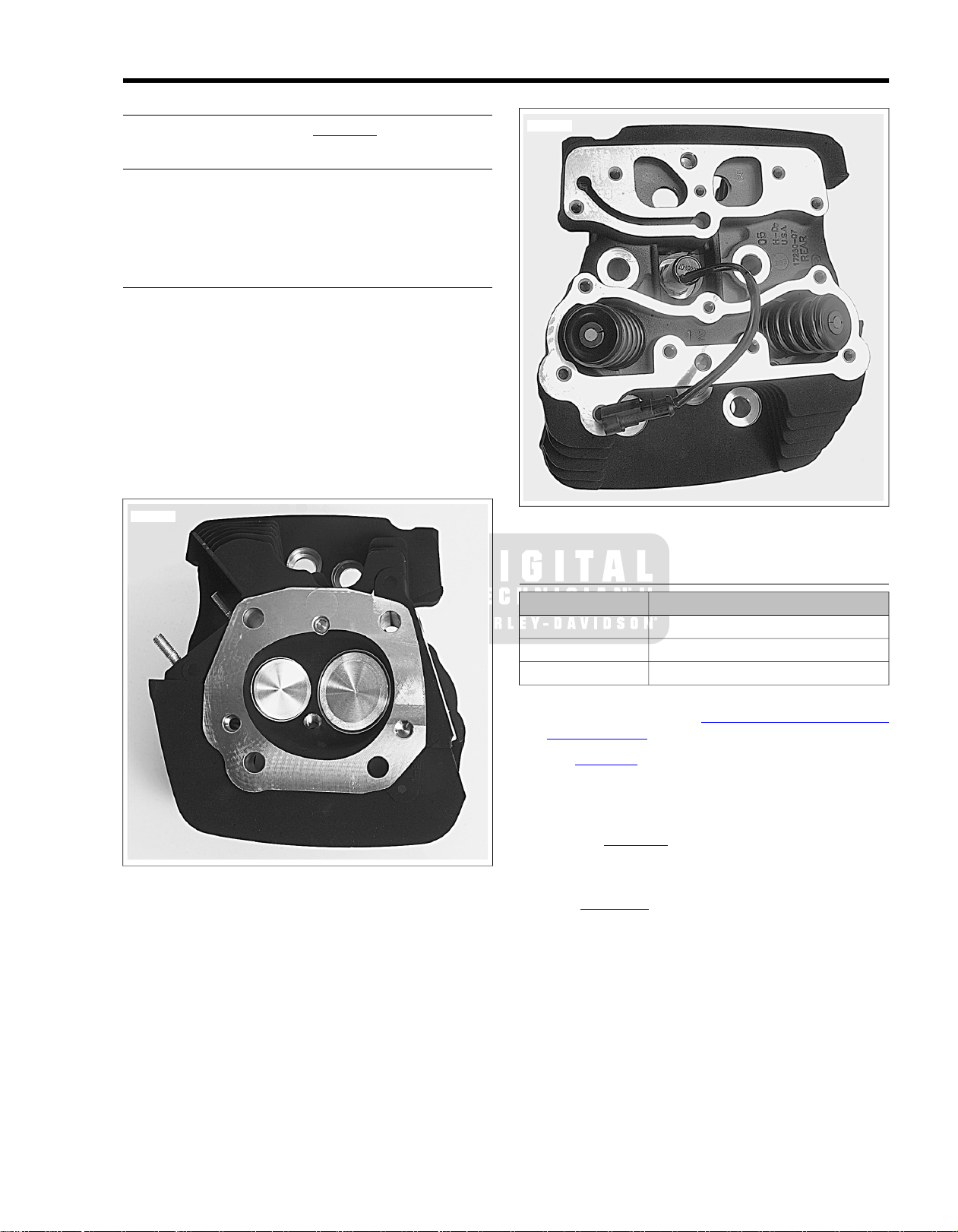
GENERAL
sm04036
sm04037
For service wear limits, refer to Table 3-16.
REMOVAL
See the Service Manual for removal of cylinder heads.
NOTE
Separate ACR connectors from the rear [203R] and front [203F]
cylinder heads when removing the heads from the cylinders.
DETERMINING SERVICE
To determine if cylinder head disassembly and reconditioning
is necessary.
1. Raise valve ports of cylinder head to strong light source.
If light is visible around edges of seats, then move to
DISASSEMBLY to recondition cylinder head.
2. Fill ports at top of cylinder head with solvent.Wait ten full
seconds and then check for leakage into combustion
chamber. If solvent leakage into combustion chamber is
evident, then move to DISASSEMBLY to recondition cylinder head.
3.3CYLINDER HEAD
Figure 3-1. Combustion Chamber
Figure 3-2. Spring/Valve Stack and ACR
DISASSEMBLY
TOOL NAMEPART NUMBER
VALVE SPRING COMPRESSORHD-34736-B
CYLINDER HEAD HOLDING FIXTUREHD-39786
ACR SOLENOID SOCKETHD-48498
1. Use the ACR SOLENOID SOCKET (Part No. HD-48498)
to remove the ACR. See 8.16 AUTOMATIC COMPRES-
SION RELEASE.
2. See Figure 3-3. Obtain the CYLINDER HEAD HOLDING
FIXTURE (Part No. HD-39786) and proceed as follows:
a. Thread the 12 mm end of the tool into the spark plug
hole of the cylinder head.
b. See Figure 3-4. Clamp tool in vise at a 45 degree
angle (or one that offers a comfortable working position).
3. See Figure 3-5. Obtain the VALVE SPRING COMPRESSOR (Part No. HD-34736-B) and proceed as follo ws:
a. Place tool over cylinder head so that the blunt end is
centered on the valve head and adapter at end of
forcing screw is seated on the valve spring retainer.
b. Rotate forcing screw to compress valve springs.
c. If spring retainer has not broken free of tapered
keepers, give head of tool a sharp tap with a soft
mallet. Using magnetic rod or small screwdriver,
remove the keepers from the valve stem groove.
d. Rotate forcing screw to release the valve spring
compression.
2008 FLHTCUSE3 Service: Engine 3-5
Page 74

4. Remove the spring retainer and inner and outer valve
2
1
sm04038
sm04039
2
2
1
sm02495
springs.
5. Slide the valve from the valve guide.
6. Using pliers, twist and remove the valve guide seal from
the top of the valve guide. Discard the valve guide seal.
7. Remove the spring seat from the cylinder head.
8. Mark the bottom of the valve "F(ront)" or "R(ear)" to
indicate the cylinder head from which it was removed.
Also, separate and tag tapered keepers, valve springs,
spring retainers and spring seats so that they are installed
on the same valve at time of assembly.
9. Repeat to remove the other valve.
10. Release the cylinder head holding fixture from the vise
and then remove the tool from the spark plug hole.
1. 14 mm end
2. 12 mm end
Figure 3-3. Cylinder Head Holding Fixture (Part No.
HD-39786-A)
1. Holding fixture
2. Compressor
Figure 3-5.Valve Spring Compressor (P art No. HD-34736-B)
CLEANING
1. Remove old gasket material from cylinder head. Gasket
material left on sealing surfaces will cause leaks.
2. Remove all carbon deposits from combustion chamber
and machined surfaces of cylinder head. Exercise caution
to avoid removing any metal material. For best results,
use an air tool with a worn wire brush. Scr aping may result
in scratches or nicks.
3. To soften stubborn deposits, soak the cylinder head in a
chemical solution, such as GUNK HYDRO-SEAL or other
carbon and gum dissolving agent. Repeat last step as
necessary.
Figure 3-4. Install Cylinder Head Holding Fixture in Vise
3-6 2008 FLHTCUSE3 Service: Engine
Compressed air can pierce the skin and flying debris from
compressed air could cause serious eye injury. Wear
safety glasses when working with compressed air. Never
use your hand to check for air leaks or to determine air
flow rates. (00061a)
4. Thoroughly clean the cylinder head, spring retainers,
tapered keepers, valves, inner and outer valve springs
and spring seats in a non-volatile cleaning solution or
solvent. Follow up with a thorough wash in hot soapy
water. Blow dry with compressed air.
Page 75
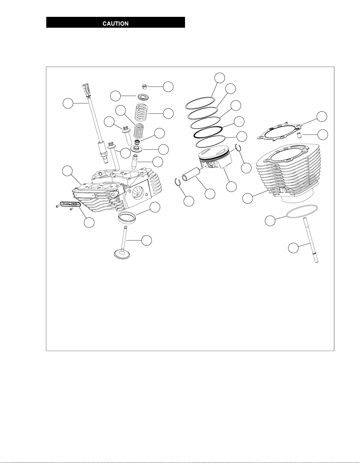
Do not use glass or sand to bead blast surfaces exposed
5
1
8
9
20
6
18
25
19
22
11
3
2
21
26
10
4
14
13
12
7
16
17
15
23
24
24
21
sm04040
to engine oil. Blasting materials can lodge in pores of the
casting. Heat expansion releases this material which can
contaminate oil resulting in engine damage. (00534b)
NOTES
• If bead blasting is used, use walnut shells or other soft
cleaning materials.
• Be aware that bead blasting materials may also enter
threaded holes adversely affecting fastener engagement
and torque indication. Carefully cover all threaded holes
if bead blasting is employed.
14.1. Cylinder head gasketAutomatic compression release (ACR)
16.3. Ring dowelSpring retainer
18.5. Cylinder studInner spring
20.7. Piston pinSpring seat
22.9. Top compression ringCylinder head bolt, short (2)
24.11. Oil railCylinder head
26.13. Screamin' Eagle nameplateValve
2. 15.Tapered keepers Cylinder
4. 17.Outer spring O-ring seal
6. 19.Valve guide seal Piston
8. 21.Valve guide Circlip (2)
10. 23.Cylinder head bolt, long (2) Second compression ring
12. 25.Valve seat Oil rail spacer
Figure 3-6. Cylinder Head/Cylinder/Piston Assemblies (Exploded View)
2008 FLHTCUSE3 Service: Engine 3-7
Page 76

INSPECTION
TOOL NAMEPART NUMBER
VALVE GUIDE HONEHD-34723
VALVE GUIDE CLEANING BRUSHHD-34751
CYLINDER TORQUE PLATESHD-48627
VALVE SPRING TESTERHD-96796-47
Cylinder Head
1. Check for scratches and nicks on all gasket sealing surfaces.
2. With the combustion chamber side facing upward, set a
straightedge diagonally across the length of the cylinder
head intersecting the upper and lower corners of the
gasket surface. Slide a feeler gauge beneath the
straightedge to check the head for w arpage. Chec king the
opposite diagonal, repeat the procedure to verify that the
gasket surface is flat (especially if a head gasket was
blown). Discard the head if any low spot is 0.006
inch (0.15 mm) or greater.
NOTE
For good results, use one of the CYLINDER TORQUE
PLATES (Part No. HD-48627) in lieu of the straightedge. Lay
the upper plate flat on the machined surface of the head. As
a preliminary check, see if the plate rocks from side to side. A
head on which the plate rocks is immediately suspect. Insert
a feeler gauge between the plate and head at various locations
to see if warpage exceeds above specification.
3. Verify that oil passageways are open and clean.
Valve Guides
1. Inspect external surfaces for cr acks (particularly the com-
bustion chamber side). Replace the guide if any cracks
are found.
2. To verify cleanliness of valve guides, lightly hone using
the VALVE GUIDE HONE (Part No. HD-34723) and then
scrub with the VALVE GUIDE CLEANING BRUSH (Part
No. HD-34751) to remove any dust or debris. Polish the
valve stem with fine emery cloth or steel wool to remove
carbon buildup, and then check valve stem to guide
clearance as follows:
a. Carefully measure the inside diameter of the valve
guide using an inside ball micrometer.
b. Measure the outside diameter of the valve stem with
an outside micrometer.
c. The clearance is the difference between the two
measurements. The valve stem and/or guide are
excessively worn if the clearance exceeds the limits
shown in Table 3-25. To determine if the guide is
excessively worn and must be replaced, repeat
measurements using a new valve.
Valves
1. Replace the valve if there is evidence of burning or
cracking.
2. Inspect the end of the valve stem for pitting or uneven
wear. Replace the valve if either of these conditions are
found.
3. Inspect for burrs around the valve stem keeper groove.
Remove burrs with a fine tooth file if found.
4. To determine if the valve stem is excessively worn, see
VALVE GUIDES above.
Valve Springs
1. Inspect springs for broken or discolored coils. Replace
springs if either of these conditions are found.
2. Set the intake and exhaust v alve springs on a lev el surface
and use a straightedge to check for proper squareness
and height.
3. Check free length of inner and outer springs using a dial
vernier caliper or load test with the VALVE SPRING
TESTER (Part No. HD-96796-47). Replace springs if free
length or compression force do not meet specifications.
See 3.1 SPECIFICATIONS: ENGINE.
Tapered Keepers
1. Inspect parts for damage or rust pits. Replace as necessary.
2. Inspect inboard side of tapered keepers for excessive
wear. Upraised center must be pronounced and fit snugly
in valve stem groo ve. Place keepers into groo ve and verify
that they grip tightly without sliding.
Valve Seats
1. Inspect seats for cracking, chipping or burning. Replace
seats if any evidence of these conditions are found.
2. Check seats for recession by measuring valve stem protrusion.
Table 3-25. Service Wear Limits
V ALVE STEM T O GUIDE CLEARANCEVALVE
0.0038 in. (0.0965 mm)Intake
0.0038 in. (0.0965 mm)Exhaust
3-8 2008 FLHTCUSE3 Service: Engine
Page 77

REPLACING VALVE GUIDES
2
1
3
sm04193
sm04041
1
2
sm02498
TOOL NAMEPART NUMBER
HD-34740
HD-34740
VALVE GUIDE AND VALVE GUIDE
SEAL HANDLE
VALVE GUIDE AND VALVE GUIDE
SEAL HANDLE
VALVE GUIDE CLEANING BRUSHHD-34751
CYLINDER HEAD SUPPORT STANDHD-39782-A
CYLINDER HEAD SUPPORT STANDHD-39782-A
CYLINDER HEAD HOLDING FIXTUREHD-39786
RATCHETING TAP HANDLEHD-39847
RATCHETING TAP HANDLEHD-39847
VALVE GUIDE REAMERHD-39932
REAMER LUBRICANTHD-39964
REAMER LUBRICANTHD-39964
VALVE GUIDE INSTALLERHD-48628
Removal
1. See Figure 3-7. Obtain the CYLINDER HEAD SUPPOR T
STAND (Part No. HD-39782-A) and proceed as follows:
a. Insert sleeve of intake or exhaust seat adapter into
tube at top of support stand.
b. Position cylinder head so that valve seat is centered
on seat adapter. Support stand ensures that valve
guide and seat are perpendicular. If perpendicularity
is not achieved, the cylinder head valve guide bore
will be damaged during the press procedure.
1. Intake seat adapter
2. Exhaust seat adapter
3. Cylinder head support stand
Figure 3-7. Cylinder Head Support Stand (HD-39782-A)
Figure 3-8.Valve Guide & Valve Guide Seal Handle
(HD-34740)
NOTE
Do not press out the valve guide from the bottom of the cylinder
head. Carbon buildup on the combustion chamber side of the
guide can deeply gouge the cylinder head bore diminishing
the likelihood of achieving the proper interference fit and possibly requiring replacement of the cylinder head casting.
2. See Figure 3-8. At the top of the cylinder head, insert
V ALVE GUIDE AND V ALVE GUIDE SEAL HANDLE (Part
No. HD-34740) into valve guide bore until stopped by
shoulder.
3. See Figure 3-9. Center valve guide driver under ram of
arbor press. Apply pressure until valve guide drops free
of cylinder head. Discard the valve guide.
1. Valve guide driver
2. Cylinder head stand
Figure 3-9. Remove Valve Guide
2008 FLHTCUSE3 Service: Engine 3-9
Page 78

1
3
2
2
1
sm02299
Installation
1. Check valve guide to valve bore clearance.
a. Measure the outside diameter of a new standard
valve guide.
b. Measure the cylinder head valve guide bore. The
valve guide should be 0.0020-0.0033 in. (0.051-0.084
mm) larger than the bore.
c. If clearance is not within specification, then select an
oversized valve guide. Refer to Table 3-26.
NOTE
Since some material is typically removed when the guide is
pressed out, it is normal to go to the next larger valve guide
for the proper interference fit.
2. See Figure 3-7 and Figure 3-10. Obtain the CYLINDER
HEAD SUPPORT STAND (Part No. HD-39782-A), VALVE
GUIDE AND V ALVE GUIDE SEAL HANDLE (Part No. HD-
34740) and VALVE GUIDE INSTALLER (Part No. HD-
48628). Proceed as follows:
a. See Figure 3-10. Insert sleeve of intake or exhaust
seat adapter into tube at top of support stand. Position
cylinder head so that valve seat is centered on seat
adapter.
NOTE
Support stand ensures that valve guide and seat are perpendicular. If perpendicularity is not achieved, cylinder
head valve guide bore will be damaged during the press
procedure.
b. Apply petroleum jelly to lightly lubricate external sur-
faces of valv e guide. Spread lubricant so that thin film
covers entire surface area.
c. At top of cylinder head, start valve guide into bore.
d. Place installer sleeve ov er valv e guide, and then insert
tapered end of valve guide driver into installer slee ve.
e. Center valve guide driver under ram of arbor press
and apply pressure only until valve guide is started
in bore and then back off ram slightly to allow guide
to center itself.
f. Verify that support stand and driver are square.
Center driver under ram and press valve guide further
into bore, but then back off ram again to allow valve
guide to find center.
g. Repeat previous step and then apply pressure to
driver until installer sleeve contacts machined area
of cylinder head.
Table 3-26. Oversized Valve Guides
MMIN.VALVE GUIDE
0.0250.001Intake
0.050.002
0.080.003
0.0250.001Exhaust
0.050.002
0.080.003
1. Valve guide driver
2. Valve guide installer sleeve
3. Cylinder head stand
Figure 3-10. Install Valve Guide
NOTE
Always back off ram to allow the valve guide to find center.
Pressing guide into cylinder head in one stroke can bend driver ,
break guide, distort cylinder head casting and/or damage cylinder head valve guide bore.
3-10 2008 FLHTCUSE3 Service: Engine
3. See Figure 3-3. Obtain the CYLINDER HEAD HOLDING
FIXTURE (Part No. HD-39786) and proceed as follows:
a. Thread the 12 mm end of the tool into the spark plug
hole of the cylinder head.
b. Clamp tool in vise at a 45 degree angle (or one that
offers a comfortable working position).
Page 79

NOTES
1
2
sm04042
sm04043
• Valve guides must be reamed to within 0.0005-0.0001
in. (0.013-0.0025 mm) of finished size.
• For best results, do not push on reamer or apply pressure
to the reamer handle.While excessive pressure results in
a rough cut, bore will be tapered if pressure is not centrally
applied.
• Never back reamer out of valve guide or bore will be
damaged.
4. See Figure 3-11. Obtain the VALVE GUIDE
REAMER (Part No. HD-39932), RATCHETING TAP
HANDLE (Part No. HD-39847) and REAMER LUBRICANT (Part No. HD-39964). Proceed as follows:
a. Install tap handle (2) on reamer (1).
b. Apply a liberal amount of reamer lubricant to valve
guide bore and bit of reamer. Start bit of reamer into
bore at top of cylinder head.
c. See Figure 3-12. Placing thumb on drive socket of
RATCHETING TAP HANDLE (Part No. HD-39847),
apply slight pressure on reamer while rotating in a
clockwise direction. Squirt additional lubricant onto
reamer and into guide as necessary.
d. Continue rotating RATCHETING TAP HANDLE (Part
No. HD-39847) until entire bit has passed through
valve guide bore and shank of reamer rotates freely.
e. Remove tap handle from reamer , and carefully pulling
on bit, draw shaft of reamer out combustion chamber
side of valve guide.
NOTE
Abrasive particles can damage machined surfaces and plug
oil passageways possibly resulting in engine failure.
5. Direct compressed air into the valve guide bore to remov e
any metal shavings or debris.
Figure 3-12. Ream Valve Guide Bore
6. See Figure 3-13. Clean v alve guide bore with the VALVE
GUIDE CLEANING BRUSH (HD-34751).
7. See Figure 3-14. Obtain the 8 mm VALVE GUIDE FLEX
HONE (HD-34723) and REAMER LUBRICANT (Part
No. HD-39964). Proceed as follows:
a. Install hone in a high speed electric drill.
b. Apply reamer lubricant to finishing stones of hone and
valve guide bore.
c. Start finishing stones of hone into bore.
d. See Figure 3-15. Activating the drill, move the entire
length of the finishing stone arrangement forward and
backward through the bore for 10 to 12 complete
strokes.Work for a crosshatch pattern of approxim-
ately 60°.
NOTE
Abrasive particles can damage machined surfaces and plug
oil passageways possibly resulting in engine failure.
8. Direct compressed air into the valve guide bore to remov e
any debris and then clean with the VALVE GUIDE
CLEANING BRUSH (Part No. HD-34751). See
Figure 3-13.
NOTE
Always verify v alve stem to valv e guide clearance after honing,
since a worn reamer may cut the bore undersize.
9. Measure the inside diameter of the valve guide with an
inside ball micrometer. Measure the outside diameter of
the valve stem with an outside micrometer .The valve stem
1. Valve guide reamer
2. Ratcheting tap handle
Figure 3-11.Valve Guide Reamer and Ratcheting Tap
Handle
may be excessiv ely worn or the valve guide bore undercut
if the clearance is not within the limits (low end preferab le)
shown in Table 3-27.
10. Using cleaning solvent, thoroughly clean valv e guide bore.
Scrub valve guide bore with the VALVE GUIDE
CLEANING BRUSH (Part No. HD-34751).
2008 FLHTCUSE3 Service: Engine 3-11
Page 80

Table 3-27. New Parts Limits
sm04044
sm04045
sm04046
sm04047
V ALVE STEM T O GUIDE CLEARANCEVALVE
0.0011-0.0029 in. (0.028-0.074 mm)Intake
0.0011-0.0029 in. (0.028-0.074 mm)Exhaust
NOTE
For best results, use a thin engine oil and clean valve guide
bore with the type of swabs or patches found in gun cleaning
kits. Continue to wipe bore until clean cloth shows no evidence
of dirt or debris.
Compressed air can pierce the skin and flying debris from
compressed air could cause serious eye injury. Wear
safety glasses when working with compressed air. Never
use your hand to check for air leaks or to determine air
flow rates. (00061a)
11. Clean valves, cylinder head and valve seats in solvent.
Follow up with a thorough wash in hot soapy water. Blow
dry with low pressure compressed air.
Figure 3-15. Hone Valve Guide Bore
Figure 3-13.Valve Guide Cleaning Brush
Figure 3-14. 8mm Valve Guide Flex Hone
Figure 3-16. Scrub Valve Guide Bore
3-12 2008 FLHTCUSE3 Service: Engine
Page 81

ASSEMBLY
1
2
sm04048
TOOL NAMEPART NUMBER
VALVE SPRING COMPRESSORHD-34736-B
HD-34740
1. Obtain the CYLINDER HEAD HOLDING FIXTURE (Part
No. HD-39786) and proceed as follows:
a. Thread the 12 mm end of the tool into the spark plug
hole of the cylinder head.
b. Clamp tool in vise at a 45 degree angle (or one that
offers a comfortable working position).
2. Slide spring seat over valve guide until it contacts the
machined area on the cylinder head casting. Use a little
grease to hold the spring seat in position, if necessary.
At the time of disassembly, all parts should have been marked
or tagged so that they are installed on the same valve (and in
the same head).
3. Run the V AL VE GUIDE CLEANING BR USH (Part No. HD-
34751) through the valve guide bore to v erify cleanliness.
4. Using TORCO MPZ or another suitable product, apply a
liberal amount of engine assembly lube to valve stem.
5. From the bottom of the cylinder head, insert the valve stem
into the valve guide.
6. To distribute the assembly lube evenly around the valve
stem and guide, hand spin the valve as it is installed.Work
the valve back and forth in the bore to verify that it slides
smoothly and seats properly.
7. Remove the valve and apply a second coat of assembly
lube to the valve stem. Install the valv e in the v alv e guide.
8. Retract the valve so that the stem is not visib le abo ve the
top of the valve guide.
9. Using isopropyl alcohol or other suitable degreaser, thoroughly clean external surface of valve guide until completely free of grease and oil.
Do not apply LOCTITE to inside of valve guide seal or top of
valve guide or v alve may stick to seal resulting in loss of compression and valve sticking.
10. Obtain tube of LOCTITE RC/620 HIGH TEMPERATURE
RET AINING COMPOUND (green). Carefully apply Loctite
to valve guide seal seating surface on outside diameter
of valve guide. Ex ercise caution to k eep compound out of
valve guide bore.
VALVE GUIDE AND VALVE GUIDE
SEAL HANDLE
VALVE GUIDE CLEANING BRUSHHD-34751
CYLINDER HEAD HOLDING FIXTUREHD-39786
VALVE GUIDE SEAL INSTALLERHD-48644
NOTE
NOTE
Failure to install plastic capsule can cause the valve stem
seal to catch the edge of the valve stem keeper groove.
The resulting damage can cause leakage around the valve
stem, excessive oil consumption and valve sticking.
(00535b)
11. See Figure 3-17. Push on head of valve until it contacts
the valve seat. Placing finger at head of valve to keep
valve seated, slide plastic capsule ov er valv e stem tip and
keeper groove.
12. See Figure 3-18. Apply a v ery thin film of clean H-D 20W50
engine oil to capsule. Slide new valve guide seal over
capsule and down valve stem until contact is made with
top of valve guide. Remove capsule from valve stem tip.
1. Plastic capsule
2. Spring seat
Figure 3-17. Install Plastic Capsule on Valve Stem
2008 FLHTCUSE3 Service: Engine 3-13
Page 82

1
2
sm04049
sm04051
sm04052
5
2
1
4
6
3
sm04052
1. Plastic capsule
2. Valve guide seal
Figure 3-18. Install Valve Guide Seal
13. See Figure 3-19. Obtain the VALVE GUIDE SEAL
INST ALLER (P art No. HD-48644) and proceed as f ollows:
a. Slide the installer tool over the valv e guide seal using
valve stem as pilot.The tool bore allows inser tion of
the valve stem, while the counterbore fits over the
valve guide seal.
b. See Figure 3-20. Using a small hammer, gently tap
the end of the tool until it lightly bottoms on the
installed spring seat. For best results, brace the cylinder head to prevent mov ement during seal installation.
NOTES
• Repeated blows on installer after seal is in place will cause
seal distortion resulting in leakage around the valve stem,
excessive oil consumption and valve sticking.
• See Figure 3-21. If an arbor press is the pref erred method
of valve guide seal installation, use the VALVE GUIDE
SEAL INSTALLER (Part No. HD-48644) with the VALVE
GUIDE AND V ALVE GUIDE SEAL HANDLE (Part No. HD-
34740).
• Do NOT remove valve after seal is installed. Removing
the valve after seal installation will cause the valve guide
seal to catch the edge of the valve stem keeper groove.
The resulting damage will lead to leakage around the valve
stem, excessive oil consumption and valve sticking.
Figure 3-20. Seat Valve Guide Seal
1. Valve guide & valve guide seal handle
2. Valve guide seal installer
3. Valve guide seal
4. Valve
5. Valve guide
6. Valve seat
Figure 3-21. Using Arbor Press to Install Valve Guide Seal
Figure 3-19.Valve Guide Seal Installer
3-14 2008 FLHTCUSE3 Service: Engine
14. Apply a liberal amount of assembly lube to valv e stem tip
and keeper groove.
15. Install the inner and outer valve springs over the valve
guide. Fit the spring retainer on top of the inner and outer
Page 83

valves springs. Like the spring seat, the smaller diameter
flange fits inside the inner valve spring.The larger diameter
flange separates the inner and outer springs.
16. Obtain the V AL VE SPRING COMPRESSOR (P art No. HD34736-B) and proceed as follows:
a. Place tool over cylinder head so that the blunt end is
centered on the valve head and adapter at end of
forcing screw is seated on the valve spring retainer.
b. Rotate forcing screw to compress valve springs.
c. With the tapered side down, fit the keepers into the
valve stem groove. For best results, apply a dab of
grease to the inboard side of the keepers before
installation and use a magnetic rod for easy place-
ment.
d. Arranging tapered keepers so that the gaps are ev enly
spaced, turn forcing screw to release valve spring
compression.
17. Tap the end of the valve stem once or twice with a soft
mallet to ensure that tapered keepers are tightly seated
in the valve stem groove.
18. Repeat all previous steps to install the other valv e components.
19. V erify that the copper seal washer is in place on the ACR.
20. Apply three equally spaced dots of LOCTITE 246
THREADLOCKER MEDIUM STRENGTH/HIGH TEMPERATURE around the lower third of the threads. Tighten to
11-15 ft-lbs (14.9-20.3 Nm). See 8.16 AUTOMATIC
COMPRESSION RELEASE.
21. Release the cylinder head holding fixture from the vise
and then remove the tool from the spark plug hole.
22. Cover the cylinder head to protect it from dust and dirt
until time of installation.
INSTALLATION
NOTE
Over-compressing the valv e spring can damage the valve guide
seal resulting in leakage around the valve stem, excessive oil
consumption and valve sticking.
See Service Manual for cylinder head installation procedure.
2008 FLHTCUSE3 Service: Engine 3-15
Page 84

GENERAL
sm04055
sm04056
See Figure 3-22. Though Twin Cam 110 pistons differ from
Twin Cam 96 in specification and appearance, piston service
procedures are the same except for measuring the nominal
diameter. See PISTON in SUBASSEMBLY SERVICE AND
REPAIR in the Service Manual. For service wear limits, refer
to Table 3-19.
MEASURING PISTON
1. Allow the piston to cool to room temperature.
2. See Figure 3-23.With a pencil or marker, mark the piston
on each side of the skirt across the thrust faces (perpendicular to the piston pin bore) 0.394 in. (10 mm) from the
bottom edge.
NOTE
Set the piston skirt down on a level table and use a rule to
measure 0.394 in. (10 mm) high on the skirt.
3. Using a micrometer at the marks, measure the nominal
diameter of the piston.
4. Use a dial bore gauge to measure the piston ring travel
zone in the cylinder bore.
NOTE
For Cylinder Bore Measurement: See CYLINDER in SUBASSEMBLY SERVICE AND REPAIR in the Service Manual.
5. Replace piston and/or cylinder if running clearance
exceeds 0.003 in. (0.076 mm).
3.4PISTONS
Figure 3-22.Twin-Cam 110 Piston
Figure 3-23. 0.394 in. (10 mm)
3-16 2008 FLHTCUSE3 Service: Engine
Page 85

2
4
1
3
sm02506
INSPECTION
TOOL NAMEPART NUMBER
CYLINDER TORQUE PLATESHD-33446-B
SNAP-ON TORQUE ANGLE GAUGETA360
NOTE
Failure to use cylinder torque plates can produce measurements that vary by as much as 0.001 in. (0.025 mm), possibly
resulting in the use of parts that are not suitable for service.
1. See Figure 3-24. To simulate an assembled cylinder for
accurately measuring cylinder taper and out-of-round
conditions, as well as for boring, honing or deglazing,
obtain the CYLINDER TORQUE PLATES (Part No. HD33446-B). Install the torque plates as follows:
a. Remove o-ring seal from cylinder sleeve, if installed.
b. Place used head gasket over two dowel pins at top
of cylinder.
c. Install brass jaws or shop towels around teeth of vise
to prevent damage to tool. Clamp stepped side of
lower plate in vise with the simulated split line
(machined strip) facing away.
d. See Figure 3-25. Lightly oil threads and shoulders of
four bolts (1) with clean H-D 20W50 engine oil. Slide
four bolts all the wa y through holes of lower plate (2)
until washers contact outboard side.
e. Slide cylinder down bolts with the indent in the cooling
fins facing upward.
f. With the two dowel pins and head gasket in place,
align holes in upper plate with ends of bolts. Blind
holes in upper plate accommodate dowel pins in cylinder. Alternately tighten four bolts into upper plate in
a crosswise pattern until finger tight.
g. See Figure 3-26. Tighten the bolts to 120-144 in-
lbs (13.6-16.3 Nm) in the sequence shown.
h. Following the same sequence, tighten each bolt to
15-17 ft-lbs (20.3-23.1 Nm).
i. Using a grease pencil, mark a straight line on one of
the bolts continuing the line over onto the low er plate.
Repeat step for remaining three bolts.
j. Using the marks as a guide, tur n each bolt 1/4 turn
or 90°. Be sure to tighten the bolts in the sequence
shown in Figure 3-26.
NOTE
For best results, obtain SNAP-ON TORQUE ANGLE
GAUGE (Part No.TA360).
k. For purposes of inspection, remove the assembly
from the vise and place on bench top.
3.5BORING AND HONING CYLINDERS
1. Bolts
2. Lower plate
3. Upper plate
4. Vise grip step
Figure 3-24. Cylinder Torque Plates
NOTE
Maximum cylinder wear occurs at the very top of top ring travel.
Minimum wear occurs below ring travel. Failure to measure
the cylinder at these points may result in a faulty decision
regarding the suitability of the cylinder for continued use.
2. See Figure 3-27. Using an inside micrometer or dial bore
gauge, check cylinder bore for out-of round and taper.
Proceed as follows:
a. At the top of the piston ring travel zone, starting about
0.50 in. (12.70 mm) or from the top of the cylinder,
measure the cylinder diameter at two locations; parallel and perpendicular to the crankshaft. Record the
readings.
b. Repeat the two measurements at the center of the
piston ring travel zone.
c. Repeat the measurements again at the bottom of the
bore at a point below the piston ring travel zone.
d. Rebore the cylinder if the parallel and perpendicular
measurements at either the top, middle or bottom of
the bore vary by more than 0.002 in. (0.051 mm).
This indicates an out-of-round condition.
e. Rebore the cylinder if the top, middle and bottom bore
diameters either parallel or perpendicular to the
crankshaft vary by more than 0.002 in. (0.051 mm).
This indicates excessive taper.
3. Continue with cylinder service.
a. If cylinders are not scuffed or scored and are not worn
beyond the service limits, see Deglazing Cylinder in
the Service Manual.
b. If cylinders are worn beyond the service limits, then
they must be rebored and/or honed to accept the next
standard oversize piston. See 3.5 BORING AND
HONING CYLINDERS, Cylinder Bore Finished Size.
2008 FLHTCUSE3 Service: Engine 3-17
Page 86
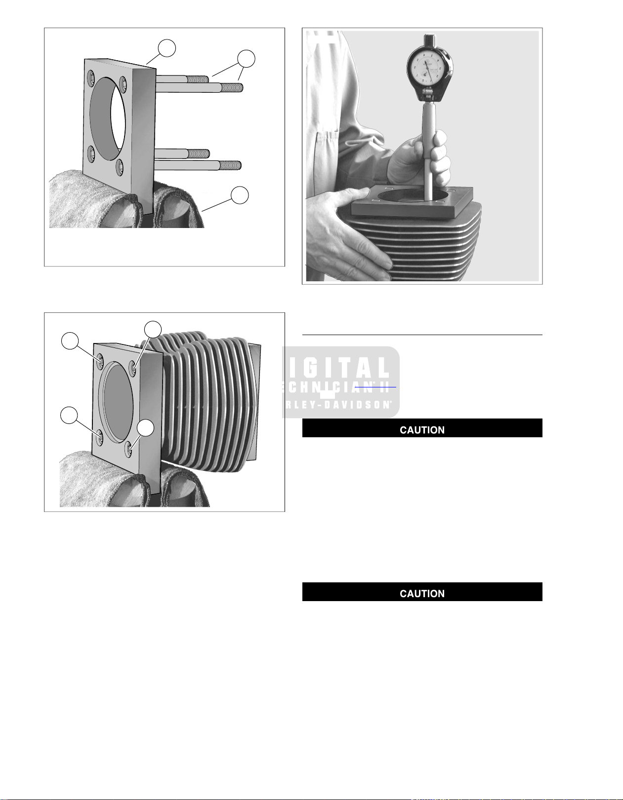
3
2
1
sm02530
3
1
2
4
sm02531
sm02532
1. Bolt (4)
2. Lower plate
3. Vise
Figure 3-25. Attaching Cylinder Torque Plates
Figure 3-26. Cylinder Torque Plate Bolt Sequence
Figure 3-27. Measure for Out-of-Round and Taper
CYLINDER BORE FINISHED SIZE
1. For cylinder removal, cleaning, inspection, boring and
honing and installation, see CYLINDER in the Service
Manual.
2. Refer to Table 3-28. Bore the cylinder to 0.003 in. (0.08
mm) under the desired finished size. See BORING and
HONING CYLINDER in the Service Manual.
An incorrect cross hatch pattern or too fine a hone will
result in insufficient oil retention and possible piston
seizure and/or high oil consumption. (00538b)
3. Hone the cylinder to its finished size using a 280 grit rigid
hone followed b y a 240 grit flexible ball hone. Honing m ust
be done with the torque plates attached. All honing must
be done from the bottom (crankcase end) of the cylinder.
Work for a 60° crosshatch pattern.
4. Stop frequently to examine the cylinder bore and/or take
measurements. Remember, a precise 60° cross hatch
pattern in the piston travel area is important.
3-18 2008 FLHTCUSE3 Service: Engine
Failure to remove all abrasive particles may result in premature cylinder, piston and ring wear and engine failure.
(00537b) .
5. Thoroughly wash the cylinder bore with liquid dish soap
and warm water to remove all abrasive particles and
residual girt. Continue cleaning until a clean cloth shows
no evidence or dirt or debris.
6. Immediately apply a thin film of clean engine oil to a clean
white paper towel and thoroughly wipe the inside of the
cylinder to prevent the cylinder bore from rusting.
Page 87

NOTE
sm04057
After wiping the cylinder with a clean, oiled paper towel, the
towel will be dark with contamination. Repeat this process
using a new lightly oiled paper towel each time until the towel
remains white.The cylinder is now clean.
7. With the cylinder at room temperature, check the piston
clearance in the cylinder in which the piston will run. See
INSPECTION under PISTON in Service Manual.
8. For cylinder installation, see CYLINDER in Service Manual.
PISTON ORIENTATION
See Figure 3-28.When replacing a piston, orient the piston so
that the etched arrow on the top of the piston faces forward.
Table 3-28. Oversize Pistons and Cylinder Bores
Figure 3-28. Piston Orientation Arro w (arrow points to front
of engine)
CYLINDER BORE FINISHED SIZEPISTON
MAXIMUMMINIMUMSIZETYPE
4.0005 in. (101.613 mm)4.0000 in. (101.6 mm)STDStandard
4.0055 in. (101.740 mm)4.0050 in. (101.727 mm)0.005 in. (0.13 mm)Oversize
4.0105 in. (101.867 mm)4.0100 in. (101.854 mm)0.010 in. (0.25 mm)
2008 FLHTCUSE3 Service: Engine 3-19
Page 88

sm04058
4
1
2
3
1
2
5
sm04059
GENERAL
With the exception of the top center crankcase bolt, crankcase
service is identical to original equipment. See the Service
Manual for complete procedure.
ASSEMBLY
TOOL NAMEPART NUMBER
HD-39361-B
HD-97225-55C
1. Install left crankcase half in engine stand so that the split
line face is vertical.
2. See Figure 3-29.To pre v ent damage to the sprock et shaft
(roller) bearing, slide CRANKSHAFT GUIDE (Part No. HD42326-A) over end of sprocket shaft.
3. Slide flywheel assembly into left case half and remove
tool.
4. Tip crankcase in engine stand so that flywheel pinion shaft
is pointing straight up.
O-rings that are missing, distorted, pinched or otherwise damaged will result in either oil leakage or low oil pressure. Use of
the wrong o-ring will have the same results. Since many o-rings
are similar in size and appearance, always use new o-rings
keeping them packaged until use to avoid confusion.
5. Install new o-rings over two ring dowels in split line face
of right case half.
6. Apply a small bead of sealant approximately 0.056 in. (1.4
mm) wide to the split line face. For best results, use HighPerformance Sealant (gray), (Part No. HD-99650-02).
7. T o pre vent damage to the crankshaft (roller) bearing, slide
CRANKSHAFT GUIDE (Part No. HD-42326-A) over end
of crankshaft until it contacts shoulder on shaft.
8. See Figure 3-30. Slide bearing in right crankcase half ov er
end of crankshaft to mate case halves. Remove tool.
SPROCKET SHAFT OIL SEAL
INSTALLER
CRANKSHAFT GUIDEHD-42326-A
SPROCKET SHAFT BEARING
INSTALLER
NOTE
3.6CRANKCASE ASSEMBLY
1. Water pipe insulation
2. Crankshaft guide
3. Left crankcase
4. Crankshaft bearing
5. Right crankcase
Figure 3-30. Crankshaft Guide
Figure 3-29. Crankshaft Guide
3-20 2008 FLHTCUSE3 Service: Engine
NOTE
See Figure 3-31.The center upper bolt (1) is longer than the
remaining eight crankcase bolts. If any of the other bolts are
installed in that position, the threads will not engage the threads
in the crankcase and the bolt will spin. If the center upper bolt
is installed in a different location, the head of the bolt will be
standing above the crankcase.
Page 89

9. Start the nine crankcase bolts and tighten:
1
4
8
2
6
9
3
7
5
sm04060
sm04061
a. Alternately turn each crankcase bolt until finger tight.
b. In sequence, tighten the crankcase bolts to 10 ft-
lbs (13.6 Nm).
c. In sequence, tighten each bolt to 15-19 ft-lbs (20.3-
25.8 Nm).
10. Rotate crankcase in the engine stand so that the stator
mount flange (sprocket shaft side) is facing upward.
11. Slide thrust washer over sprocket shaft with "THIS SIDE
OUT" facing out (and the chamfer inboard).
NOTE
If using OE part without markings, orient as required to preserve
existing wear pattern.
12. To install new oil seal into bearing bore, obtain pilot, Nice
bearing, large flat washer and handle from SPROCKET
SHAFT BEARING INSTALLER (P art No. HD-97225-55C)
and proceed as follows:
a. Verify that seal lip garter spring is in place on both
sides of seal.
b. Thread pilot onto sprocket shaft until contact is made
with shoulder.
c. With the lettering facing outside, slide oil seal over
pilot until it contacts bearing bore.
d. See Figure 3-32. Slide SPR OCKET SHAFT OIL SEAL
INSTALLER (Part No. HD-39361-B) over pilot until it
contacts oil seal.
e. Slide Nice bearing and large flat washer over pilot
until contact is made with seal installer.
f. Thread handle onto pilot shaft.
g. See Figure 3-33. Rotate handle in a cloc kwise direc-
tion until oil seal installer makes firm contact with
crankcase stator mount.
h. Remove handle, flat washer, Nice bearing, seal
installer and pilot from sprocket shaft.
Figure 3-31. Crankcase Torque Sequence (left side)
Figure 3-32. Sprocket Shaft Oil Seal Installer
13. Slide sprocket shaft spacer over end of sprocket shaft.
Push spacer into oil seal until seated against bearing race.
2008 FLHTCUSE3 Service: Engine 3-21
Page 90

1
1
sm02348
1. Seal Installer
Figure 3-33. Sprocket Shaft Oil Seal Installer
3-22 2008 FLHTCUSE3 Service: Engine
Page 91
3.7OIL COOLER
sm04062
OPERATION
For engine oil flow through the engine, See ENGINE OIL FLO W
under GENERAL INFORMATION in Tour ing Models Service
Manual.
See Figure 3-34. The flow of oil to the cooler is controlled by
a thermostat in an adapter located between the oil filter and
the filter mount.
Under pressure from the crankcase, engine oil flows from the
crankcase oil filter mount into a passage in the oil cooler
adapter.The thermostat is located across the supply and return
ports. It consists of a temperature sensitive element compressed between a spring and a threaded plug.
When the engine oil temperature is below 200° F (93° C), an
open thermostat allows the largest percentage of engine oil in
the supply port to pass through to the return port and then to
the oil filter. A smaller percentage flows through the supply
hose to the oil cooler.
When oil temperature exceeds 200° F (93° C), the thermostat
closes and all the oil flows through the supply port and hose
to the oil cooler.
The oil circulates through the finned tubes of the cooler to dissipate heat and returns to the oil cooler adapter through a
return hose.
The oil is filtered before returning to the crankcase.
NOTE
Regardless of whether the thermostat is closed or open, oil is
always pressurized in the oil cooler adapter, the oil cooler
supply hose, the oil cooler and the oil return hose.
At every service interval, the oil cooler fins should be checked
for dirt and debris.
REMOVAL
TOOL NAMEPART NUMBER
HOSE CLAMP PLIERSHD-97087-65B
1. Cover the front fender to protect finish.
2. Place a container under the motorcycle to catch excess
oil.
NOTE
Dispose of oil in accordance with local regulations.
3. See Figure 3-35. Remove the fasteners (1) and washers
(2) securing the oil cooler (3) and cover (4) to the frame
mounting bracket (5) and pull the cooler and cov er forward.
4. Use the HOSE CLAMP PLIERS (Part No. HD-97087-65B)
to cut the clamps (6) at the oil hoses (7, 8) at the oil cooler
adapter (9).
5. Remove the oil cooler with cover.
6. The oil cooler should be inspected for dirt and debris.
7. See Figure 3-34. If remo ving the hoses from the oil cooler,
cut clamps on the supply and return hoses.
INSTALLATION
TOOL NAMEPART NUMBER
HOSE CLAMP PLIERSHD-97087-65B
1. If replacing the hoses, install new hose clamps on the
ends of the hoses.
2. Push the supply and return hoses over the expanded tubes
on the oil cooler.
3. Use HOSE CLAMP PLIERS (Part No. HD-97087-65B) to
clamp the hoses to the oil cooler.
4. Holding the cover ov er the cooler, install on the mounting
bracket.Tighten fasteners to 80-110 in-lbs (9.2-12.4 Nm).
5. See Figure 3-35. Push the oil hoses into the fittings on the
oil cooler adapter.
NOTE
Verify that the protective cap is in place on the frame stud in
the path of the oil hoses.
6. Use HOSE CLAMP PLIERS (Part No. HD-97087-65B) to
clamp the hoses to the oil cooler adapter.
7. Check oil level and add oil if required.
8. After running engine, inspect oil cooler hose fittings for
leaks.
Figure 3-34. Oil Cooler
2008 FLHTCUSE3 Service: Engine 3-23
Page 92
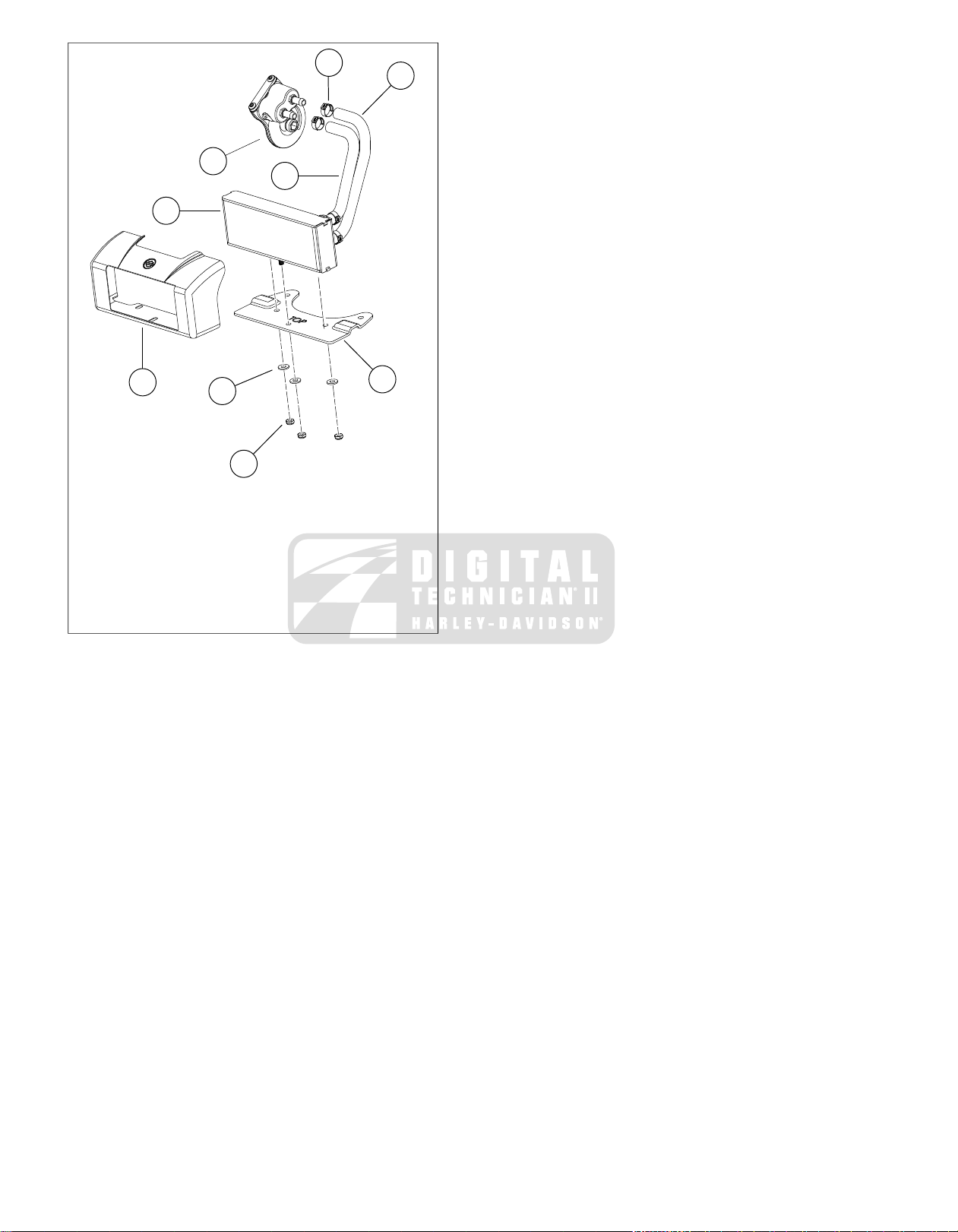
1
5
7
2
4
8
9
3
6
sm04063
1. Fastener (3)
2. Washer (3)
3. Oil cooler
4. Cover
5. Mounting bracket
6. Hose clamp (4)
7. Return oil hose
8. Supply oil hose
9. Oil cooler adapter
Figure 3-35. Oil Cooler
3-24 2008 FLHTCUSE3 Service: Engine
Page 93

REMOVAL
2
1
3
sm04064
1
3
2
sm04065
TOOL NAMEPART NUMBER
OIL FILTER WRENCHHD-42311
HOSE CLAMP PLIERSHD-97087-65B
1. Place a container under motorcycle to catch excess oil.
2. Bend a cardboard funnel and fit to motorcycle to route
fluid away from regulator and oil cooler toward the container.
3. Use OIL FILTER WRENCH (Part No. HD-42311) to
remove the oil filter.
4. Use HOSE CLAMP PLIERS (Part No. HD-97087-65B) to
remove the clamps from the oil hoses at the adapter.
5. See Figure 3-36. Remove the oil filter adapter (1).
6. Remove the oil cooler adapter (2) with the gasket (3).
3.8OIL COOLER ADAPTER
DISASSEMBLY
1. See Figure 3-37. Inspect the crankcase mating surface
and, if necessary, remove any old gasket material.
2. Remove the inspection cover (1) and gasket.
3. Remove the two oil cooler line fittings.
NOTE
Replace the oil cooler adapter if the thermostat is not functioning.
4. Clean the oil filter mount surface of old filter gasket
material.
5. Clean the oil passages in solvent.
6. Inspect the oil passages and the oil cooler mount.
1. Oil filter adapter
2. Oil cooler adapter
3. Gasket
Figure 3-36. Oil Cooler Adapter
1. Inspection cover
2. Gasket
3. Positioning flange
Figure 3-37. Oil Cooler Adapter
ASSEMBLY
1. Install the inspection passage cover and new gasket.
2. Apply one drop LOCTITE 246 THREADLOCKER MEDIUM
STRENGTH/HIGH TEMPERATURE to the fasteners and
tighten to 90-120 in-lbs (10.2-13.6 Nm).
3. See Figure 3-38. Install the supply (1) and return (2) port
oil line fittings.
a. Finger tighten.
b. From finger tight, turn 2-3 more turns.
INSTALLATION
TOOL NAMEPART NUMBER
HOSE CLAMP PLIERSHD-97087-65B
NOTE
To avoid cross threading tapped holes, exercise care when
starting oil filter adapter.
1. See Figure 3-37. Match the positioning flanges (3) on the
oil cooler adapter to the oil filter mount.
NOTE
The oil cooler adapter will only fit in one location.
2. Apply LOCTITE 246 THREADLOCKER MEDIUM
STRENGTH/HIGH TEMPERATURE to the threads of the
oil filter adapter.
3. Holding the adapter in place, thread the oil filter adapter
fitting through the adapter with the internal hex facing
outward.Tighten to 18-22 ft-lbs (24.4-27.3 Nm).
4. Install the oil hoses with new clamps.
2008 FLHTCUSE3 Service: Engine 3-25
Page 94
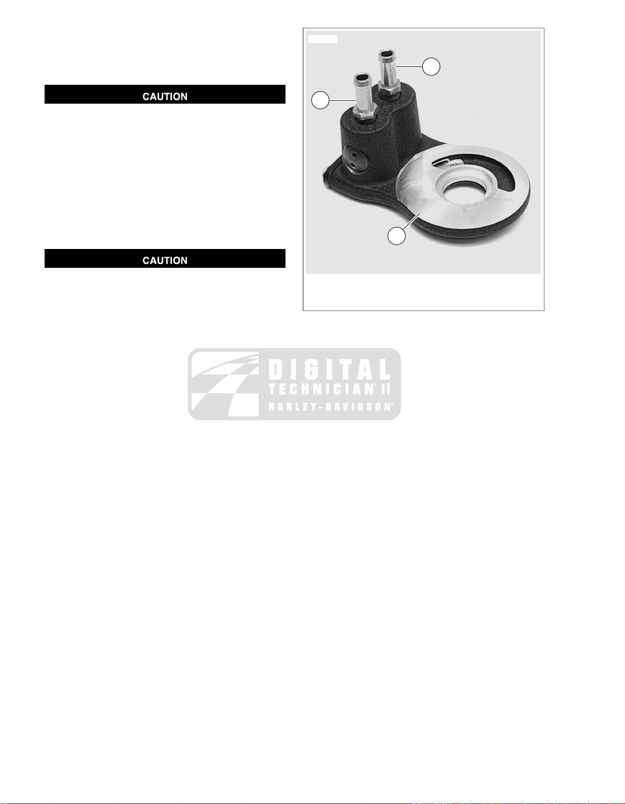
5. Use HOSE CLAMP PLIERS (Part No. HD-97087-65B) to
1
2
3
sm04066
install clamp.
6. Install a new oil filter. See ENGINE OIL/FILTER in the
Touring Models Service Manual.
Oil level cannot be accurately measured on a cold engine.
For pre-ride inspection, with motorcycle leaning on jiffy
stand on level ground, oil should register on dipstick
between arrows when engine is cold. Do not add oil to
bring the level to the FULL mark on a COLD engine.
(00185a)
7. Perform an oil level COLD CHECK. See the Touring
Models Service Manual.
NOTE
Add only enough oil to bring the level between the two arro ws
on the dipstick.
Do not operate the engine when the oil level is below the
add mark on the dipstick at operating temperature. Engine
damage will result. (00187b)
8. Start engine and check for oil leaks.
9. When at operating temperature, perform an oil level HOT
CHECK. See the Touring Models Service Manual.
1. Supply port
2. Return port
3. Oil filter gasket surface
Figure 3-38. Oil Line Fittings on Adapter
3-26 2008 FLHTCUSE3 Service: Engine
Page 95

SUBJECT............................................................................................................................PAGE NO.
4.1 AIR CLEANER COVER.............................................................................................................4-1
FUEL SYSTEM
Page 96

NOTES
Page 97

GENERAL
1
2
3
sm04069
3
2
1
sm04070
The air cleaner assembly is functionally identical to that of the
standard models, with the exception of the air cleaner cover,
decorative cover trim and cover mounting screws.
For other air cleaner assembly procedures, see the Service
Manual.
REMOVAL
1. See Figure 4-1. Remove two screws (3) and decorative
cover trim (2).
2. See Figure 4-2. Remove screw (2) and air cleaner cover
(1).
INSTALLATION
1. See Figure 4-2. Install air cleaner cover (1). Make sure
rubber cover seal (3) fits all the way around the cover.
2. Install screw (2).Tighten to 36-60 in-lbs (4.1-6.8 Nm).
3. See Figure 4-1. Install decorative cover trim (2) and two
screws (3).
4. Tighten to 27-32 in-lbs (3.1-3.6 Nm).
4.1AIR CLEANER COVER
1. Air cleaner cover
2. Screw
3. Cover seal
Figure 4-2. Air Cleaner Cover and Screw
1. Air cleaner cover
2. Decorative cover trim
3. Screw (2)
Figure 4-1. Air Cleaner Cover Trim and Screws
2008 FLHTCUSE3 Service: Fuel System 4-1
Page 98

NOTES
4-2 2008 FLHTCUSE3 Service: Fuel System
Page 99

SUBJECT............................................................................................................................PAGE NO.
5.1 SPECIFICATIONS: STARTER...................................................................................................5-1
ELECTRIC STARTER
Page 100

NOTES
 Loading...