

Page 1
2009 Touring Models Owner's Manual: Safety First https://www.harley-davidson.com/en_US/Content/Pages/Owners/om/200...
M
Safety First
Safe Operating Rules: Touring Models
Motorcycles are different from other vehicles. They operate, steer, handle and
brake differently. Unskilled or improper use could result in loss of control, death or
ser ious injury. (00556c)
Take a rider training course.
Read Owner's Manual before riding, adding accessories or servicin g.
Wear a helmet, eye protecti on an d protective clothin g.
Never tow a trai ler.
Before operating your new motorcycle it is your responsibility to read and follow the operating and
maintenance instructions in this manual, and follow these basic rules for your personal safety.
Know and respect the rules of the road (see RULES OF THE ROAD section). Carefully read and
observe the rules contained in the RIDING TIPS booklet accompanying this Owner's Manual.
Read and familiarize yourself with the contents of the MOTORCYCLE HANDBOOK for your
state.
Before starting en gin e, check for proper operation of brake, clutch , shi f ter, thr ottl e controls,
correct fuel and oil supply.
Do not use aftermarket parts and custom made front for ks which can adversely
affect performance and handling. Removing or altering factory installed parts can
adversely affect performance and could result in death or serious injury. (00001a)
Use only Har ley-Davidson approved parts an d accessories. Use of certain other
manufacturer's perfo rmance parts will void your new moto rcycle warranty. See your HarleyDavidson dealer for details.
Stop the engine when refueling or servicing the fuel system. Do not smoke or
allow open flame or sparks near ga soline. Gasoline i s extr emely flammable and
highly explosive, which could result in death or serious injury. (00002a)
When refueling your mo torcycle, the following rules should be observed.
Refu el i n a well venti lated ar ea with the engine turn ed off.
Remove fuel filler cap slo wly.
Do not smoke or allow open flames or sparks when ref ueling or servici ng the fuel system.
Do not fill fuel tank abo ve the bottom of the filler neck insert.
Leave ai r sp ace to allow for fuel expansion.
1 of 7 07/30/2011 4:41 A
Page 2

2009 Touring Models Owner's Manual: Safety First https://www.harley-davidson.com/en_US/Content/Pages/Owners/om/200...
M
Do not store motorcycle with gasolin e in ta nk within the ho me or garage w here
open flames, p ilot lights, sparks or electric motors are presen t. Gasoline is
extremely flammable and highly explosive, which could result in death or serious
i njury. (00003a)
Engine exhaust from this product contains chemicals known to the State of
California to cause cancer, and birth defects or other reproductive harm. (00004f)
Wheel weights on wheels without spokes contain lead and lead compounds,
chemicals known to the State of California to cause cancer, and birth defects or
other reproductive harm. (00356d)
Do not run motorcycle in a closed garage or confined area. Inhaling motorcycle
exhaust, which contains poisonous carbon monoxide gas, could result in death or
ser ious injury. (00005a)
The jiffy stand loc k s when placed in the full forward (do wn) position with vehicle
weight on it. If the jiffy stand is not in the full forward (down) position with vehicle
weight on it, the vehicle can fall over which could result in death or serious injury.
(00006a)
Be sure jiffy stand is fully retracted before riding. If jiffy stand is not fully
retracted, it can contact the road surface causing a loss of vehicle control, which
coul d resu lt in de ath or serious injury. (00007a)
A new motorcycle must be operated according to the special break-in procedure. See
Br eak-in Riding Rule s
Operate motorcycle onl y at moderate sp eed and out of traffic u ntil you have be come
thoroughly familiar with its operation and handling characteristics under all conditions.
NOTE:
We recommend that you obtain information and formal training in the correct motorcycle riding
technique. In th e United States, the Motorcycle Safety Found ati o n
rider s afety courses. Call (949)727-3227 for i nformation.
Travel at sp eeds appropriate for road and co nditions and never tr avel faster than
posted speed limit. Excessive speed can cause loss of vehicle control, wh ich c ould
resu lt in death or se rious injury. (00008a)
.
®
offers beginning and advanced
Do not exceed the legal speed limit or drive too fast for existing conditions. Always reduce
speed when poor driving conditions exist. High speed i ncreases the influence of any other
condition affecting stability and increases the possibility of loss of control.
Pay strict attention to road surfaces and wind conditions. Any two wheeled vehicle may be
subject to upsetting forces such as wind blasts from passing trucks, holes in the pavement,
rough road surfaces, rider control error, etc. These forces may influence the handling
character istics of your motorcycle. If this ha ppens, reduce speed and gu ide th e motorcycle
with a relaxed grip to a controlled condition. Do not brake abruptly or force the handlebar.
2 of 7 07/30/2011 4:41 A
Page 3
2009 Touring Models Owner's Manual: Safety First https://www.harley-davidson.com/en_US/Content/Pages/Owners/om/200...
M
This may aggravate an u nstable condition.
Keep cargo wei g ht concentrated close to the motorcycle and as low as possible to min imi ze
the change i n the motorcycle's center of gravity. Distribute weig ht evenly on both side s of the
vehicle and do not load bulky items too far behind the rider or add weight to the handlebars
or front forks. Do not exceed maxi mu m specified load in each sad dlebag.
NOTE:
New riders should gain experience und er variou s conditions while dr iving at moderate speeds.
Operate your motorcycle def ensively. Remember , a motorcycle does not afford the same
protection as an automobile in an accident. On e of the most common accid en t situati ons
occurs when the d river of th e other vehicle fails to see or recognize a motorcycle and tu rns
left into the on-coming motorcyclist. Operate only with headlamp on.
Wear an approved helmet, clothing, and foot gear suited for motorcycle ridi ng. Bri ght or light
colors are best for greater visibility in traffic, especially at night. Avoid loo se, flowing garments
and scarves.
Avoid contact with exhaust system and wear protective clothing that completely
covers legs while riding. Exhaust pipes and mufflers get very hot when engine is
running and remain too hot to touch, even after engine is turned off. Failure to
wear protective clothing could result in burns o r other serious injury. (00009a)
When carrying passengers, it is yo ur responsibility to instruct them on proper riding
procedures. (See Riding Tips for Motorcyclist included in your Harley-Davidson Owner's Kit.)
Do not allow other individuals, under any circumstances, to operate your motorcycle unless
yo u know they are experienced, licensed riders and are thoroughly familiar with the operation
of your particular motorcycle.
Protect your motorcycl e a g a inst theft. Af ter parking your motorcycle, lock the steering head
and remove ig ni tion key from switch . Set security alarm if present.
Safe motorcycle operation requires alert mental judgment combined with a defensive driving
attitude. Do not allow fatigue, alcohol or dr ugs to endanger your safety or tha t of others.
Vehicles equipped with a sound system should have the volume adjusted to a nondistracting
level before o perating vehicle.
Maintain your motorcycle in proper operating condition in accordance with Regular Service
Intervals : 2009 Touring Models. Particularly important to motorcycle stability is proper tire
infl ation pressure, tread condition, and proper adjustment of wheel bearings and steerin g
head bear ings.
Do not operate veh icle with f orks locked. Locking th e forks restricts the vehicle's
turning ability, which could result in death or serious injury. (00035a)
Perform the service and maintenance op erations as indicated in the regular
service interval table. Lack of regular maintenance at the recommended intervals
can affect the safe operation of your motorcycle, which could result in death or
ser ious injury. (00010a)
Do not operate motorcycle with loose, worn or damaged steering or suspension
systems. Contact a H arley-Davi dson deale r for repairs. Loose, worn o r damaged
steering or suspension components can a dversely affect stability and handl in g,
which could r esult in death or serious injury. (00011a)
3 of 7 07/30/2011 4:41 A
Page 4

2009 Touring Models Owner's Manual: Safety First https://www.harley-davidson.com/en_US/Content/Pages/Owners/om/200...
M
Regularly in spect shock absorbers and front forks. Replace leaking, damaged or
worn parts that can adversely affect stability and handling, which could result in
death or serious injury. (00012a)
Use Harley-Davidson replacemen t fastener s. Aftermarket fasteners can adversely
affect performance, which could result in death or serious injury. (00013a)
See your Har ley-Davidson service manual for proper torque values.
Aftermarket fasteners may not have the specif ic pr operty requirements to perform pr oper ly.
Be sure tires are pr operl y inflated, balanced and have adequate tread. Inspec t
your tires regularly and see a Harley-David so n dealer for repl acements. Riding
with excessively worn, unbalanced or under-inflated tires can adversely affect
stability and handling, which could result in death or serious injury. (00014a)
Replace p unctured or da maged tires. In some c ases, small punctures in the tread
area may be repaired from within the demounted tire by a Harley-Davidson
dealer. Speed should NOT exceed 50 mph (80 km/h) for the first 24 hours after
repair, and the repaired tire should NEVER be used over 80 mph (130 km/h).
Failure to follow this warning could result in death or serious injury. (00015a)
Do n ot exceed the motorcycle's Gro ss Vehi cle Wei ght Rating (GVWR) or Gr oss
Axle Weight Rating (GAWR). Exceeding these weight ratings can affect stability
and handling, which could result in death or serious injury. (00016e)
GVWR is the sum of the weight of the motorcycle, accessori es, and th e maximum weight of
the r ider, pa ssenger and car g o th at can be saf ely car rie d .
GAWR is the maximum amount of weight that can be safely carri ed on each axle.
The GVWR and GAWR are sh own on the information p late located on the frame steering
head.
Do not tow a disabled motorcycle. Towing can adversely affect stabil ity and
handling, which could result in death or serious injury. (00017a)
Do not pull a trailer w ith a motorcycle. Pulli ng a trailer can cause tire overl oad,
reduced braking efficiency and adversely affect stability and handling, which could
resu lt in death or se rious injury. (00018b)
Direct contact of D.O.T. 4 brake fluid with eyes can cause irritation. Avoid eye
co ntact. In case of eye contact flush with large amounts of water an d get medical
attention. Swallowing large amounts of D.O.T. 4 brake fluid can cause digestive
discomfort. If swallowed, obtain medical attention. Use in well ventilated area.
KEEP OUT OF REACH OF CHILDREN. (00240a)
4 of 7 07/30/2011 4:41 A
Page 5
2009 Touring Models Owner's Manual: Safety First https://www.harley-davidson.com/en_US/Content/Pages/Owners/om/200...
M
Batteries, battery posts, termi nals and related accessories contain lead and l ead
compounds, and other chemical s known to the State of California to cause can cer,
and birth defects or other reproductive harm. Wash hands after handling.
(00019e)
Consult a Harley-Davidson dealer regarding any questions or problems that occur
in the operation of your motorcycle. Failure to do so can aggravate an initial
problem, cause costly repairs, cause an accident and could result in death or
ser ious injury. (00020a)
Be sure all equipment required by federal, state and local law is installed and in good operating
condition.
Do n ot open storage compartments while riding. Distractio ns wh ile riding can lead
to loss of control, which c ould result in death or serious injury. (00082a)
If ABS lamp remains on continuously, the ABS is not operating. The standard
brake system is operational, but wheel lock up can occur. Contact a HarleyDavidson Dealer to have ABS repaired. A locked wheel will skid and can cause loss
of vehicle control, which could result in death or serious injury. (00361a)
ABS cannot prevent lockup of rear wheel due to engine braking. ABS will n ot aid in
cornering or on loose/uneven surfaces. A locked wheel will skid and can cause loss
of vehicle control, which could result in death or serious injury. (00362a)
Rules of the Road
Always sound your horn, actuate your turn signals, and exercise caution when passing other
vehicles going in the same direction. Never try to pass another vehicle going in the same
direction at street intersections, o n curves, or when going up or down a hill.
At street intersections gi ve the ri ght-of-way. Do not presume you have the right-of-way, as
the other driver may not know it is your turn.
Always signal when preparing to stop, turn or pass.
All traffic signs, including those used for the control of traffic at intersections, should be
obeyed promptly. SLOW DOWN signs near schools and CAUTION signs at rail r oad crossin gs
should always be observed and your actions governed accordingly.
When inten din g to turn, sign al at least 100 feet 30.5 meters bef ore r eaching the turning poi nt.
I f turning acr oss an intersection, move over to the center line of the street (unless local rules
requ ire otherwise). Slow down when entering the intersection an d turn carefully.
Never anticipate a tr affic light. When a ch ange is indicated from GO to STOP (or vice versa) in
the traf fic control systems at intersections, slow down and wait for the lig ht to change. Never
run through a yellow or red traffic li ght.
While turning either right o r left, watch for pedestrians, animals, as well as vehicles.
Do not leave th e curb or parking area without signaling. Be sure your way is clear to enter
moving traffic. A movin g line of traf fic always has the rig ht-of-way.
Be sure your license plate is installed in the po sition specified by law and is clearly visible at all
times. K eep the pl ate clean.
Ride at a safe sp eed that is consistent with the typ e of h igh way you are on. Pa y str ict
attentio n to whether the road is dry, oily, icy or wet.
Watch for debris such as leaves or loose gravel.
Weather and traffic conditions on the high way dictate adjusting your speed and driving habits
accordingly.
5 of 7 07/30/2011 4:41 A
Page 6

2009 Touring Models Owner's Manual: Safety First https://www.harley-davidson.com/en_US/Content/Pages/Owners/om/200...
M
Accessori es an d C argo
Harley-Davidson Motor Company cannot test and make specific recommendations concerning every
accessory or combination of accessories sold. Therefore , the rider must be resp onsible f or sa fe
operation of the motorcycle when installing accessories or carrying additional weight.
See the Accessory and Cargo section in your Owner's Manual. Improper loading of
cargo or installation of accessories can affect motorcycle stability and handling,
which could r esult in death or serious injury. (00021a)
Do n ot exceed the motorcycle's Gro ss Vehi cle Wei ght Rating (GVWR) or Gr oss
Axle Weight Rating (GAWR). Exceeding these weight ratings can affect stability
and handling, which could result in death or serious injury. (00016e)
GVWR is the sum of the weight of the motorcycle, accessori es, and th e maximum weight of
the r ider, pa ssenger and car g o th at can be saf ely car rie d .
GAWR is the maximum amount of weight that can be safely carri ed on each axle.
The GVWR and GAWR are shown on the info rmation plate which is located on the frame
down tube.
Do not pull a trailer w ith a motorcycle. Pulli ng a trailer can cause tire overl oad,
reduced braking efficiency and adversely affect stability and handling, which could
resu lt in death or se rious injury. (00018b)
Accessory an d Cargo G u idelines
The following guidelines should be used when equipping a motorcycle, carrying passengers and/or
cargo.
Travel at sp eeds appropriate for road and co nditions and never tr avel faster than
posted speed limit. Excessive speed can cause loss of vehicle control, wh ich c ould
resu lt in death or se rious injury. (00008a)
Do not exceed the legal speed limit or drive too fast for existing conditions. Always reduce
speed when poor driving conditions exist. High speed i ncreases the influence of any other
condition affecting stability and increases the possibility of loss of control.
Pay strict attention to road surfaces and wind conditions. Any two wheeled vehicle may be
subject to upsetting forces such as wind blasts from passing trucks, holes in the pavement,
rough road surfaces, rider control error, etc. These forces may influence the handling
character istics of your motorcycle. If this ha ppens, reduce speed and gu ide th e motorcycle
with a relaxed grip to a controlled condition. Do not brake abruptly or force the handlebar.
This may aggravate an u nstable condition.
Keep cargo weight concentrated close to the motorcycle and as low as possible. This
mi nimi zes the change in t he motorcycle's cen ter of grav ity .
Distri bute weight evenly on both sid es of the vehicle.
Do not load bulky items too far behind the rider or add weight to the handlebars or front
forks.
Do not exceed maximum specified load in each sad dleb ag .
Luggage racks are desi gned for lightweight items. Do not overload racks.
Be sure cargo is secure and will not shift while riding and recheck the cargo perio dically.
Accessories that chang e the operator's riding p osition may in cr ease r eaction time and af f ect
handling of the motorcycle.
Additi onal el ectrical equipment may overload the motorcycle's electrical system possibly
6 of 7 07/30/2011 4:41 A
Page 7
2009 Touring Models Owner's Manual: Safety First https://www.harley-davidson.com/en_US/Content/Pages/Owners/om/200...
M
resulting in electrical system and/or component failure.
The front and/or rear guard(s) can provide limited leg and cosmetic vehicle
protection under unique circumstances. (Fall over while stopped, ver y slow speed
slide.) It is not made or intended to provide protection from bodily injury in a
collision with another vehicle or any other object. (00022a)
Lar ge sur faces such as fairings, wi ndshields, back rest s, and lu ggage racks can a dversely af fect
handling. Only genuine Harley-Davidso n items designed specifically for the motorcycle model should
be used with proper installation.
Do not use aftermarket parts and custom made front for ks which can adversely
affect performance and handling. Removing or altering factory installed parts can
adversely affect performance and could result in death or serious injury. (00001a)
Only Touring Harley-Davidson Motorcycles are suitable for sidecar use. Consult a
Harley-Davidson dealer. Use of motorcycles other than Touring models with
sidecars could result in death or serious inju ry. (00040a)
Noise Control System
Tampering
Owners are warned that removal or replacement of any noise contr ol system component may be
prohibited by law. This prohibition applies prior to vehicle sale or delivery to the ultimate purchaser.
Use of a vehicle on whi ch noise control system components have been removed or rendered
inoperative may also be prohibited by law.
7 of 7 07/30/2011 4:41 A
Page 8
2009 Touring Models Owner's Manual: Identification https://www.harley-davidson.com/en_US/Content/Pages/Owners/om/200...
M
Identification
Vehicle Identific a tion Number: Tourin g Models
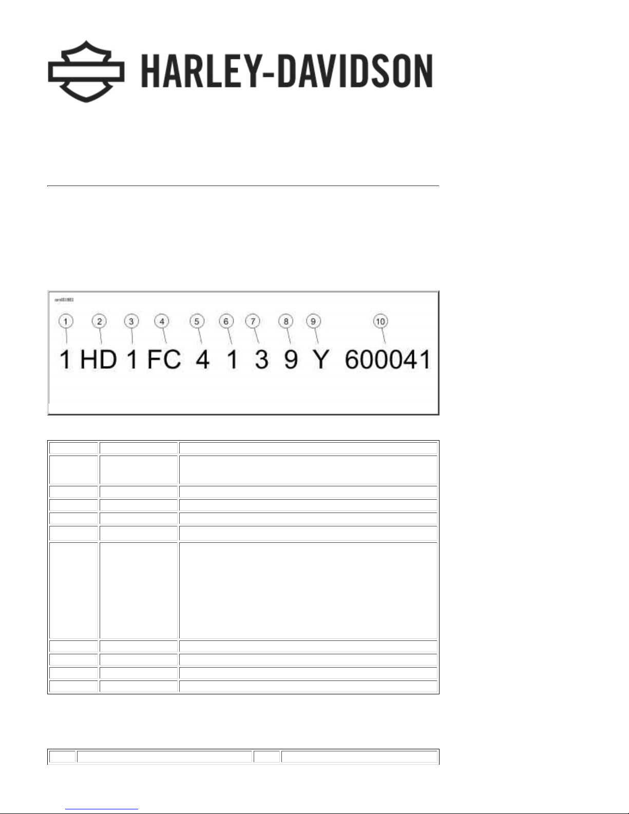
The full 17-dig it serial or Vehicle I denti fication Number (V.I.N.) is stamped on the right side of the
frame backbone at the rear of the frame behind the steering head. A label bearing the V.I.N. code is
also affixed to the l eft side of the frame behind th e steer ing head.
An abbreviated V.I.N. is stamped on the left side crankcase at the base of the rear cyli n der.
NOTE:
Always gi ve the full 17-digit Vehicle Identification N umber wh en order i ng parts o r making any inquiry
abou t yo ur motorcycle.
Typical Harley-Davidson V.I.N.: 2009 Touring Models
Harley-Davidson V.I.N. Breakdown: 2009 Touring Models
POSITION DESCRIPT ION POSSIBLE V ALUES
1 Market designation 1=Originall y manufactured for sale within the United States
5=Originally manufactured for sale outside of the United States
2 Manufacturer HD=Harley-Davidson
3 Motorcycle type 1=Heavyweig ht motorcycle (901 cc or larg er )
4 Model See V.I.N . model table
5Engine type
6 Introduction date 1=Regular
7 V.I.N. check digit Can be 0-9 or X
8 Mode l ye a r 9=2009
9 Assembly plant Y=York, PA U.S.A.
10 Sequential number Varies
4=T win Ca m 96
2=Mid-year
3=California/regular
4=Cosmetic changes and/or special introductory date
5=California/cosmetic changes and/or special introductory date
6=California/mid-year
™
, 1584 cc air-cool ed, fuel-i njected
V.I.N. Model Codes: 2009 Touring Models
CODE MODEL CODE MODEL
1 of 2 07/30/2011 4:42 A
Page 9
2009 Touring Models Owner's Manual: Identification https://www.harley-davidson.com/en_US/Content/Pages/Owners/om/200...
M
CODE MODEL CODE MODEL
FB
FLH R Road Ki ng
FG
FLHTCU Ul tra Classic® Electra Glide® with
sidecar
FS
FLTR Road Glide
FF
FLHTC Electra Glide® Classic
FW
FLH R Road Ki ng® Shrin e
®
®
FC
FLHTCU Ultra Classic® Electra Glide
FL
FLHTCU Ultra Classic® Electra Glide
Shri ne
FV
FLHT Electra Glide
KB
FLHX Street Glide
FR
FLHRC Road King® Cl assic
®
™
®
®
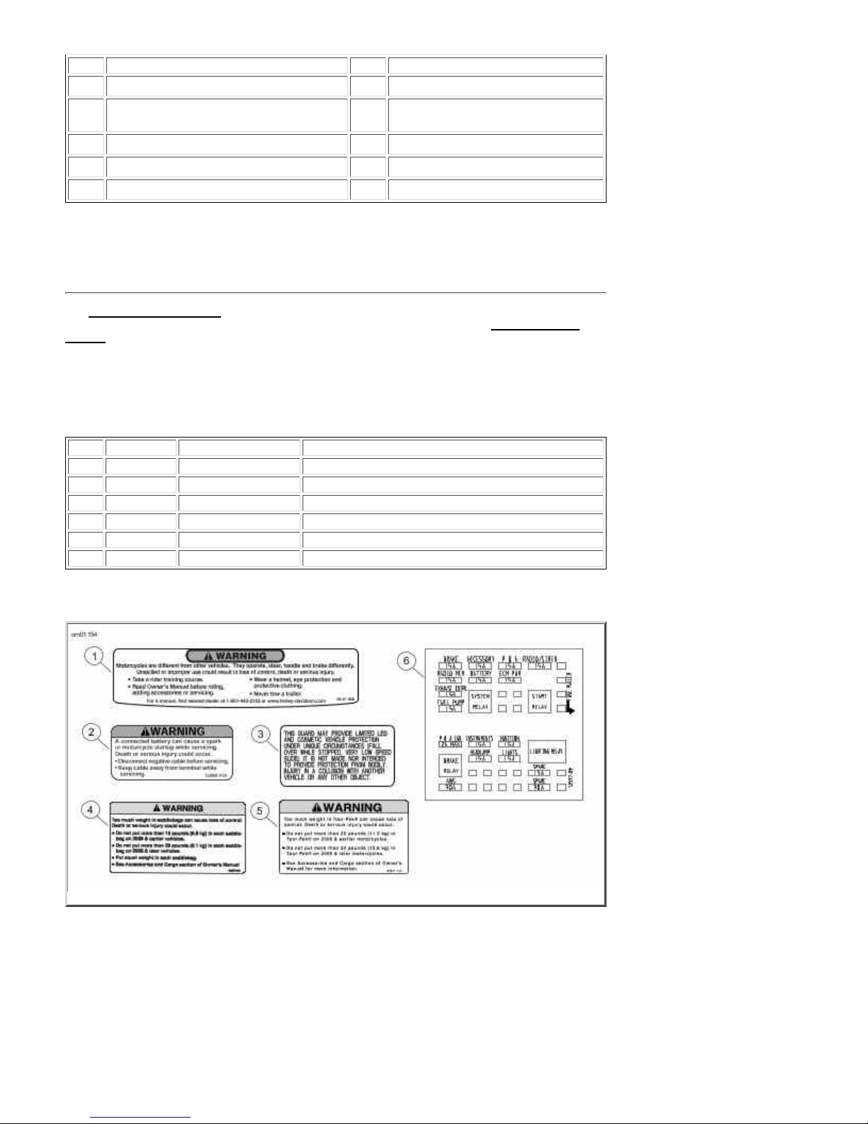
Labels
See Labels: Touring Models for safety and maintenance labels which were on the vehicle when new.
If removed, replacement labels may be purchased for your motorcycle. Refer to Labels: Touring
Models for label descriptions.
NOTE:
Some labels may be avai l able in different la nguages for destinations o utside the U. S. See a Harley-
Davidson dealer for all labels available for purchase.
Labels: Touring Models
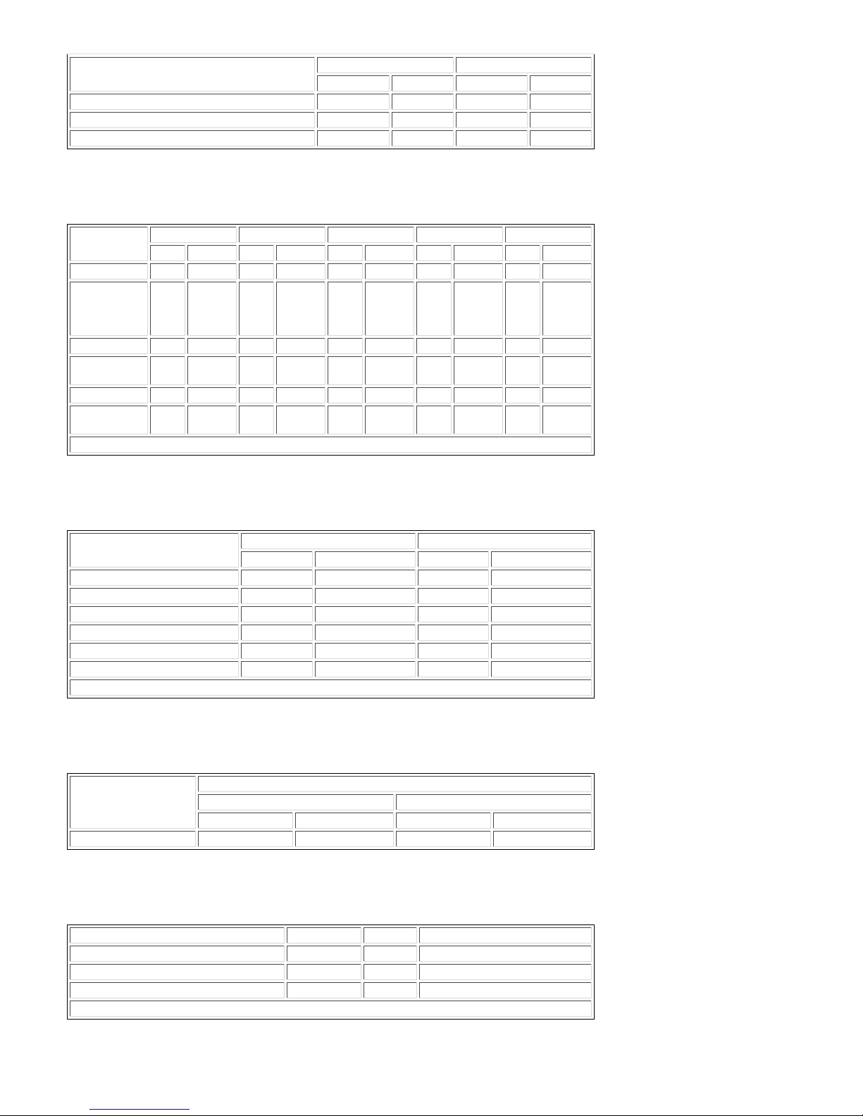
ITEM PART NO. DESCRIPTION LOCATION
1 29127-95B Gener al warnin gs Top of a ir clea ner cove r
2 15368-01A Battery warning Under seat, behind fuel tank on main harness trough
3 14148-86 Highway bar warning On front of highway bar below center mount
4 90820-93D Sadd lebag load limits Insi de saddleb ag
5 90821-74C Tour-Pak load limits Inside Tour-Pak lid
6 72537-08 Fuse block cover Und e r left s id e cover on fuse block
Labels: Touring Models
2 of 2 07/30/2011 4:42 A
Page 10
2009 Touring Models Owner's Manual: Specifications https://www.harley-davidson.com/en_US/Content/Pages/Owners/om/200...
M
Specifications
Specifications: 2009 Touring Models
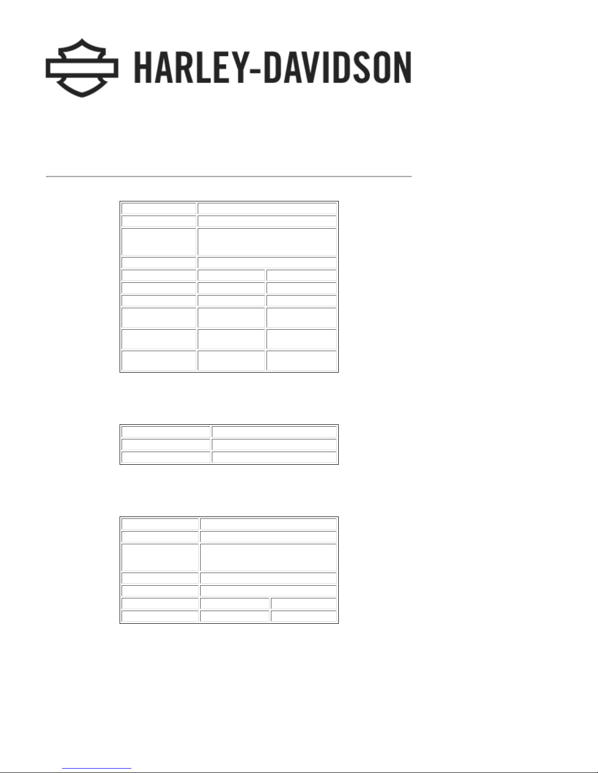
Engine: 2009 Touring Models
ITEM SPECIFICATION
Number of cylinders 2
Type 4-cycle, 45 degree
V-Type, air cooled
Compression ratio 9.2-1
Bore 3.750 in. 95.25 mm
Stroke 4.380 in. 111.25 mm
Displacement 96.00 cu. in. 1584.00 cu. cm
Torque (North
America)
Torque
(International)
Torque (Japan) 86.90 ft-l b s @
92.60 f t-l bs @
3500 RPM
90.20 f t-l bs @
3400 RPM
2500 RPM
125.57 N m @
3500 RPM
122.31 N m @
3400 RPM
117.84 N m @
2500 RPM
Transmission: 2009 Touring Models
TRANSMISSION SPECIFICATION
Type Constant mesh, foot shift
Speeds 6 forward
Ignition System: 2009 Touring Models
COMPONENT SPECIFICATION
I g nition ti ming Not adjustab le
Bat tery 12 volt, 28 amp/hr, 270 CCA
sealed an d maintenan ce f r ee
Spark plug type HD-6R12
Spark plug size 12 mm
Spark plu g gap 0.038- 0.043 in . 0.97-1.09 mm
Spark pl ug torque 12-18 ft-lbs 16.3-24.4 Nm
NOTE:
Specifications in this publication may not match those of official certification in some markets due
to timing of publication prin ti ng, var i ance in testin g methods, and/or veh i cle differences. Cu stomer s
seeking officially recognized regulatory specifications for their vehicle should refer to certification
documents and/or contact their respective dealer or distributor.
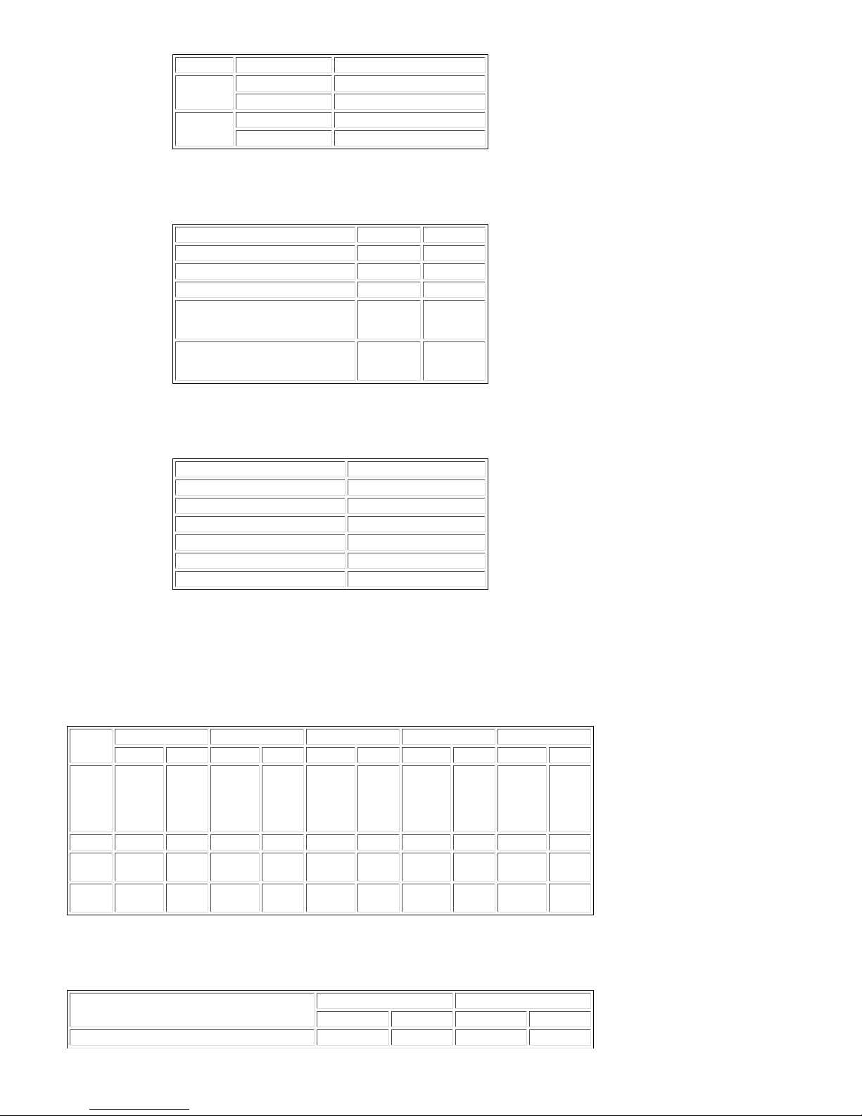
Sprocket Teeth : 2009 To uring Models
1 of 7 07/30/2011 4:43 A
Page 11
2009 Touring Models Owner's Manual: Specifications https://www.harley-davidson.com/en_US/Content/Pages/Owners/om/200...
M
DRIVE ITEM NUMBER OF TEETH
Primary Engine 34
Clutch 46
Final Transmission 32
Rear wheel 68
Capacities: 2009 Touring Models
ITEM U.S. LITERS
Fuel tank (t ota l) 6.00 gal 22.71
Low fuel warning light on 1.00 gal 3.79
Oil tank with filter 4.00 qt. 3.79
Transmission
(approximate)
Pri mary ch aincase
(approximate)
1.00 qt. 0.95
1.40 qt. 1.32
Gear Ratios: 2009 Touring Models
GEAR RATIO
1st Gear 9.593
2nd Gear 6.650
3rd Gear 4.938
4th Gear 4.000
5th Gear 3.407
6th Gear 2.875
NOTE:
Gross Vehicle Weight Rating (GVWR) (maximum allowable loaded vehicle weight) and corresponding
Gross Axle Weight Ratings (GAWR) are listed on a label located on the left side of the motorcycle on
the lower front downtube.
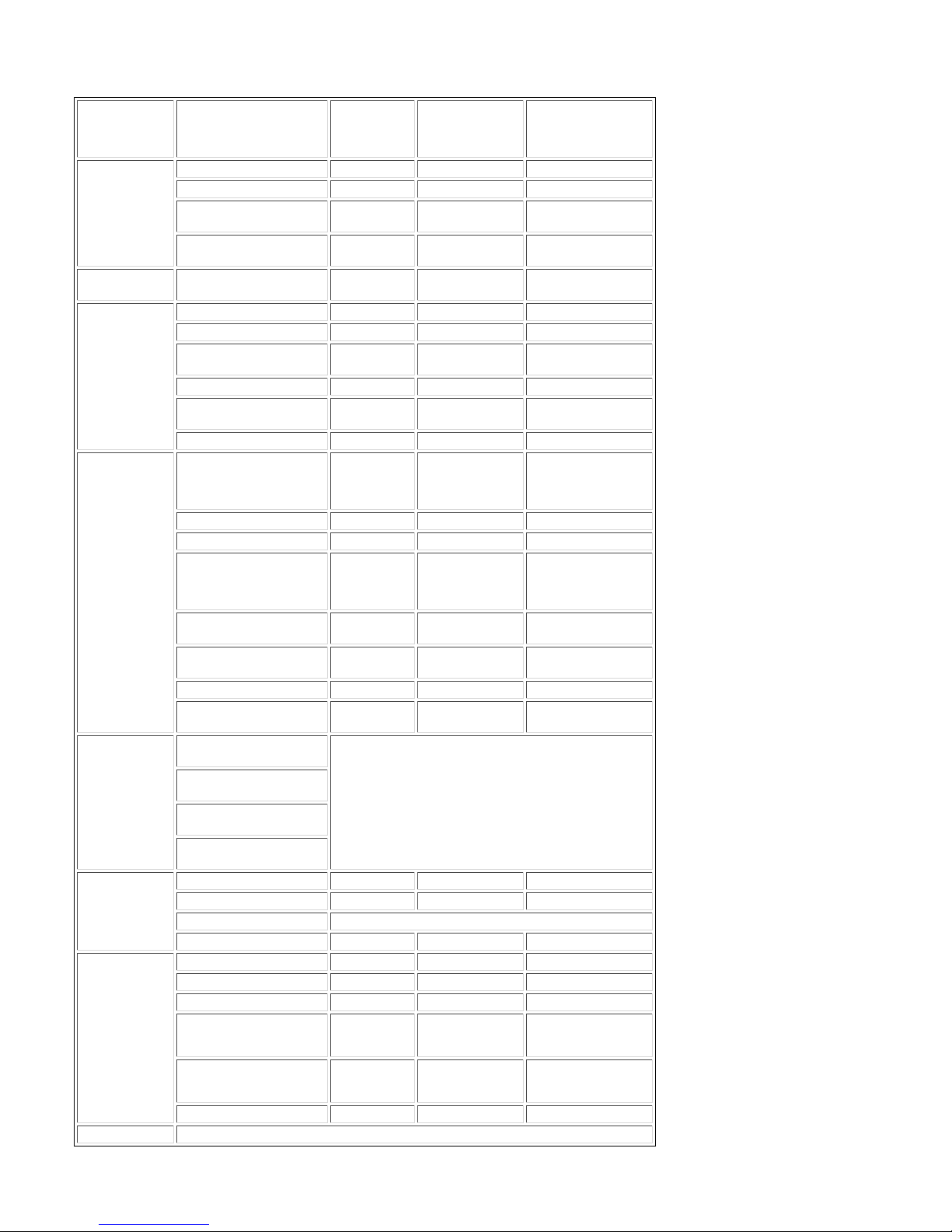
We ights: 2009 FLHT, FLHTC/U, FLTR and FLHX
ITEM FLHT FLHTC FLHTCU FLTR FLHX
LB.KGLB.KGLB.KGLB.KGLB.KG
Weight
as
shipped
from
factory
GVWR 1360.00 616.89 1360.00 616.89 1360.00 616.89 1360.00 616.89 1360.00 616.89
GAWR
front
GAWR
rear
774.00 351.08 827.00 375.12 852.00 386.46 783.00 355.16 773.00 350 .63
500.00 226.80 500.00 226.80 500.00 22 6.80 500.00 226.80 500.00 226.80
927.00 420.48 927.00 420.48 927.00 42 0.48 927.00 420.48 927.00 420.48
Weight s: 2009 FLHR and FLHRC
ITEM FLHR FLHRC
LB. KG LB. KG
Weig ht a s shipped from fac tory 775.00 351.53 773.00 350.63
2 of 7 07/30/2011 4:43 A
Page 12
2009 Touring Models Owner's Manual: Specifications https://www.harley-davidson.com/en_US/Content/Pages/Owners/om/200...
M
ITEM FLHR FLHRC
LB. KG LB. KG
GVWR 1360.00 616.89 1360.00 616.89
GAW R front 500.00 226.80 500.00 226.80
GAWR rea r 927.00 420.48 927.00 420.48
Dimensions: 2009 FLHT, FLHTC/U, FLTR and FLHX
ITEM FLHT FLHTC FLHTCU FLTR FLHX
IN. MM IN. MM IN. MM IN. MM IN. MM
Whe e l b a s e 63.54 1613.92 63.54 1613.92 63.54 1613.92 63.54 1613.92 63.54 1613.92
Overall length
(Tour-Pak in
rearmost
position)
Overall widt h 38.00 965.20 38.00 965.20 38.00 965.20 35.80 909.32 38.00 965.20
Road
clearance
Overall heigh t 61.00 1549.49 61.00 1549.49 61.00 1549.49 55.00 1397.00 52.20 1325.88
Saddle
height*
*With 180 lb . 81.7 k g ride r on se a t
95.02 2413.51 98.30 2496.82 98.63 2502.20 94.10 2390.14 95.08 2415.03
5.10 129.54 5.10 129.54 5.10 129.54 5.10 129.54 4.70 1 19.38
27.30 693.42 27.30 693.42 27.30 693.42 26.90 683.26 26.30 668.02
Dimensions: 2009 FLHR and FLHRC
ITEM FLHR FLHRC
IN. MM IN. MM
Whe e l b a s e 63.54 1613.92 63.54 1613.92
Overall length 95.02 2413.51 94.22 2393.19
Overall widt h 37. 40 949.96 37.50 952.50
Road clearance 5.10 129.54 5.10 129.54
Overall heigh t 55.10 1399.54 55.10 1399.54
Saddle heigh t * 27.30 693.42 26.90 683.26
*With 180 lb . 81.7 k g ride r on se a t
Ti re Pressures: 2009 Touring Models
MODEL TIRE PRESSURE (COLD)
FRONT REAR
PSI kPa PSI kPa
All 36 248 40 276
Tire Sizes: 2009 Touring Models
MODEL MOUNT SIZE NUMBER
FLH RC fr ont 16 i n. D407F 130/90 B16
All models except FLHRC fr ont 17 i n. D407F 130/80 B17
All models rear 16 in . D 407 180/ 65 B16
2009 vehicles use Dunlop Harley-Davidson tires only.
3 of 7 07/30/2011 4:43 A
Page 13
2009 Touring Models Owner's Manual: Specifications https://www.harley-davidson.com/en_US/Content/Pages/Owners/om/200...
M
Bulb Chart: 2009 Touring Models
LAMP DESCRIPTION
(ALL LAMPS 12 VOLT)
Hea dlamp FLHT/C/U, FLH R/C, FLHX 1 4.58/5.0 68329-03
FLTR 2 4.58/5.0 68329-03
Position l amp,
internatio nal
Position l amp, FLTR
Japan
Tail and stop
lamp
Turn sign al
lamp
Additional
lighting
Instrument
panel lamps
FLHT/C/U
FLHR/C
FLTR
FLHX
Gauge lamps
FLHR/C
Gauge lamps
FLHT/C/U
FLTR
FLHX
I tems wi th * Illu minated with LE Ds. Rep lace entire assembly upon failure.
Tail/stop lamp 1 0.59/2.10 68167-04
Front/running 2 2.25/0.59 68168-89A
Front internat ional 2 1.75 68572-64B
Front , FLH X (HDI), FL TR
(Japan)
Rear 2 2.25 68572-64B
Rear, FLTR/FLHX
internatio nal
Rear, other inter nationa l 2 1.75 68163-84
Tour-Pak side lamps
FLHTCU*
Tour-Pak t a il/stop la mps 2 0.59/2.10 68165-64
Fender t ip lamps, f ront 1 0.30 68193-95
Fender t ip lamps, rear * N/A N/A 69375-06 (FLHX)
Li cense pl ate lamp
internatio nal
Li cense pl ate lamp
FLT R/FLHX domest ic
Auxiliary lamps 2 2.1 68453-05
Auxiliary lamps
internatio nal
High beam indicator Instrument panel is illuminated with LEDs. Replace
Oil pressure indicator
Neutral indicator
Turn signal indicator
Speedometer N/A N/A N/A
Odometer N/A N/A N/A
Fuel gauge* Illuminated with LEDs. Replace assembly upon failure.
Engine N/A N/A N/A
Speedometer N/A N/A N/A
Tachometer N/A N/A N/A
Voltmeter 1 0.24 67445-00
Oil pressure indicator
FLHT/C/U
Ai r temperatur e g a uge
FLHT/C/U
Fuel gauge 1 0.24 67445-00
BULBS
REQUIRED
1 0.32 53438-92
1 0.32 53436-97
2 1.75 68163-84
2 1.75 68163-84
N/A 0.14
1 0.37 53436-97
2 0.35 52441-95
2 2.7 68851-98
entire assembly upon failure.
1 0.24 67445-00
1 0.24 67445-00
CURRENT
DRAW
AMPERAGE
0.14
HARLEY-
DAVIDSON
PART NUMBER
53788-06 (rig ht
side)
53789-06 (left s ide)
59672-09 (all bu t
FLHX)
4 of 7 07/30/2011 4:43 A
Page 14
2009 Touring Models Owner's Manual: Specifications https://www.harley-davidson.com/en_US/Content/Pages/Owners/om/200...
M
Tire Data
Match ti res, tu bes, air valves and caps to the correct whe e l rim. Contact a HarleyDavidson dealer. Mismatching can result in damage to the tire bead, allow tire
slippage on the rim or cause tire failure, which could result in death or serious
injury. (00023a)
Use only Harley-Davidson approved tires. See a Harley-Davidson dealer. Using
non-approved tires can adversely affect stability, which could result in death or
serious injury. (00024a)
Tubeless tires fitted with the correct siz e inner tubes may be used on all Harley-Davidson laced (wire
spoked) whee ls. P rotective rubber r im strips must be used wit h tub e less tires ( fitte d with correct
size i nner tu bes) when mounted on l a ced (wire spoked) wheels.
Use inner tubes on laced (wire spoked) wheels. Using tubeless tires on laced
wheels can cause air leaks, which could result in de ath or serious injury. (00025a)
Tubeless ti res are used on all Harl ey-David son cast and disc wheels.
Ti re sizes are molded on the tir e sidewal l. Inner tube sizes are printed on the tube.
Harley-D a vidson fro nt and rear tires are not the same. I nterchan ging front an d
rear tires can cause tire failure, which could result in death or serious injury.
(00026a)
Do not inflate ti re beyond maximum pressure as specified on si dewall. Over
inflated tires can blow out, whic h could result in death o r serious inj ury. (00027a)
Harley-David son tires are equipped with wear bars that run horizontally across
the tread. When wear bars become visible and only 1/32 in. (0.8 mm) tread
depth remains, replace tire immediately. Using a worn tire can adversely affect
stability and handling, which could result in death or serious injury. Use only
Harley-Davi dson approved replacement tir es. (00090b)
See Specifications: 2009 Touring Models
for tire pressures and sizes.
Gasoline Blends
Your motorcycle was designed to get the best performance and efficiency using un leaded gasoline.
Most gasoline is bl ended with alcohol and /or ether to create oxygenated blend s. The type and
amount of alcohol or ether added to the fuel is important.
5 of 7 07/30/2011 4:43 A
Page 15
2009 Touring Models Owner's Manual: Specifications https://www.harley-davidson.com/en_US/Content/Pages/Owners/om/200...
M
Do not use gasoline that contains methanol. Doing so can result i n fue l system
comp onent fail ure, en gin e damage and/ o r equipment malfunction. (00148a)
Gasolin e containin g METHYL TER TIARY BUTYL ETHER (MTBE): Gasoline/MTBE blends are a
mixture of gasoline and as much as 15% MTBE. Gasoli n e/MTBE blends can be used in your
motorcycle.
ETHANOL is a mixture of 10% ethanol (Grain alcohol) and 90% unleaded gasoline.
Gasoli ne/ethanol blends can be used in your motorcycle if the ethanol content does not
exceed 10%.
REFORMULATED OR OXYGENATED GASOLINES (RFG): Reformulated gasoline is a term used
to describe gasoline blends that are specifi cally designed to burn cleaner than other types of
gasoline, leavi ng fewer tailp ipe emissions. They are also formulated to evaporate less when
yo u are filling your tank. Reformulated gaso lines use additives to oxygenate the gas. Your
motorcycle will run normally using this type of gas and Harley-Davidson reco mmends yo u
use it when possible, as an aid to cleaner ai r in our environment.
Do not use race gas or octane boosters. Use of these fuels will damage the fuel system.
Some gasoline blends might adversely affect the starting, driveability or fuel efficiency of the
motorcycle. I f any of these problems are experienced, try a different brand of gasoli n e or gasoline
with a higher octane blend.
Fuel
Refer to Octane Ra t ings. Always use a good quali ty unleaded gasoline. Octane ratings are usually
found on the pump.
Avoid spills. Slowly remove filler cap. Do not fill above bottom of filler neck insert,
leaving air space for fuel expansion. Secure filler cap after refueling. Gasolin e is
extremely flammable and hig hly explosive, which coul d result in death or serious
injury. (00028a)
Use care when refueling. Pr essurized air in fuel tank c an force gasoline to escape
through filler tube. Gasoli ne is extremely flammable an d highly explosive, which
could resu lt in de a th or serio us injury. (00029a)
Modern service station pumps dispense a high flow of gasoline into a motorcycle fuel tank making
air entrapment and pressuriz ation a possibility.
Octane Ratings
SPECIFICATION RATING
Pump Octane (R+M)/2 91 (95 RON)
Catalytic Converter: Touring Models
Touring moto rcycles manufactured for international and California markets have a catalytic
converter in the exhaust pipe collector.
6 of 7 07/30/2011 4:43 A
Page 16

2009 Touring Models Owner's Manual: Specifications https://www.harley-davidson.com/en_US/Content/Pages/Owners/om/200...
M
Do n ot operate catalytic converter-eq uipped vehicle with engine misf ire or a
non-firing cylinder. If you operate the vehicle under these conditions, the exhaust
will become abnormally hot, which can cause vehicle damage, including emission
control loss. (00149a)
Use only unleaded fuel in catalytic converter-equipped motorcycles. Using leaded
fuel w ill damage the emission control system. (00150b)
7 of 7 07/30/2011 4:43 A
Page 17
2009 Touring Models Owner's Manual: Controls and Indicators https://www.harley-davidson.com/en_US/Content/Pages/Owners/om/200...
M
Controls and Indicators
General: C ontrols a n d Indicators
Read the CONTROLS AND IND ICATORS section b efore riding your motorcycle.
Failure to understand the operation of the motorcycle could result in death or
ser ious injury. (00043a)
Some features explained are uniq ue to certain model s. T hese features may be available as accessories
for your Harley-Davidson motorcycle. See a Harley-Davidson dealer for a complete list of accessories
that will fit your specific motorcycle.
Ignit i on/Headl a mp Key Switch : Touri n g Models
The au tomatic-on headlamp feature provides incr eased visi bility of the rider to
other motorists. B e sure headlamp is on at all times. Poor visi bility of rider to
other motorists ca n result in death or serious injury. (00030b)
See YOUR OWNER'S MANUAL section. Be sure to record all your key numbers in the space provided at
the fr ont of this book.
See Ignition/Headlamp Key Switch: Touring Models. The ignition/headlamp key switch controls
electr ical f uncti ons of the motorcycle.
Protect your vehicle agai nst theft. After parking your motorc ycle, lock the steering
head and remove ignition key from switch. Failure to lock your motorcycle may
result i n theft and/or equipment damage. (00151a)
Do not operate veh icle with f orks locked. Locking th e forks restricts the vehicle's
turning ability, which could result in death or serious injury. (00035a)
Do not lubrica te barr el locks w ith petrole um bas e d lubrican ts or graphite .
Ino perative lo cks may result. ( 00152a)
NOTES:
Harley-Davidson recommends removing key from ignition/fork lock before operating
motorcycle. If you do not remove key, it can fall out during operation.
ACCESS/ACCESSORY - Accessories and hazard warning flasher can be turned on. Instrument
lamps are on. Brake lamp and horn can be activated. Key may be removed.
1 of 27 07/30/2011 4:44 A
Page 18
2009 Touring Models Owner's Manual: Controls and Indicators https://www.harley-davidson.com/en_US/Content/Pages/Owners/om/200...
M
The lamps illuminate when the switch is in the IGNITION position, as required by law in some
localities.
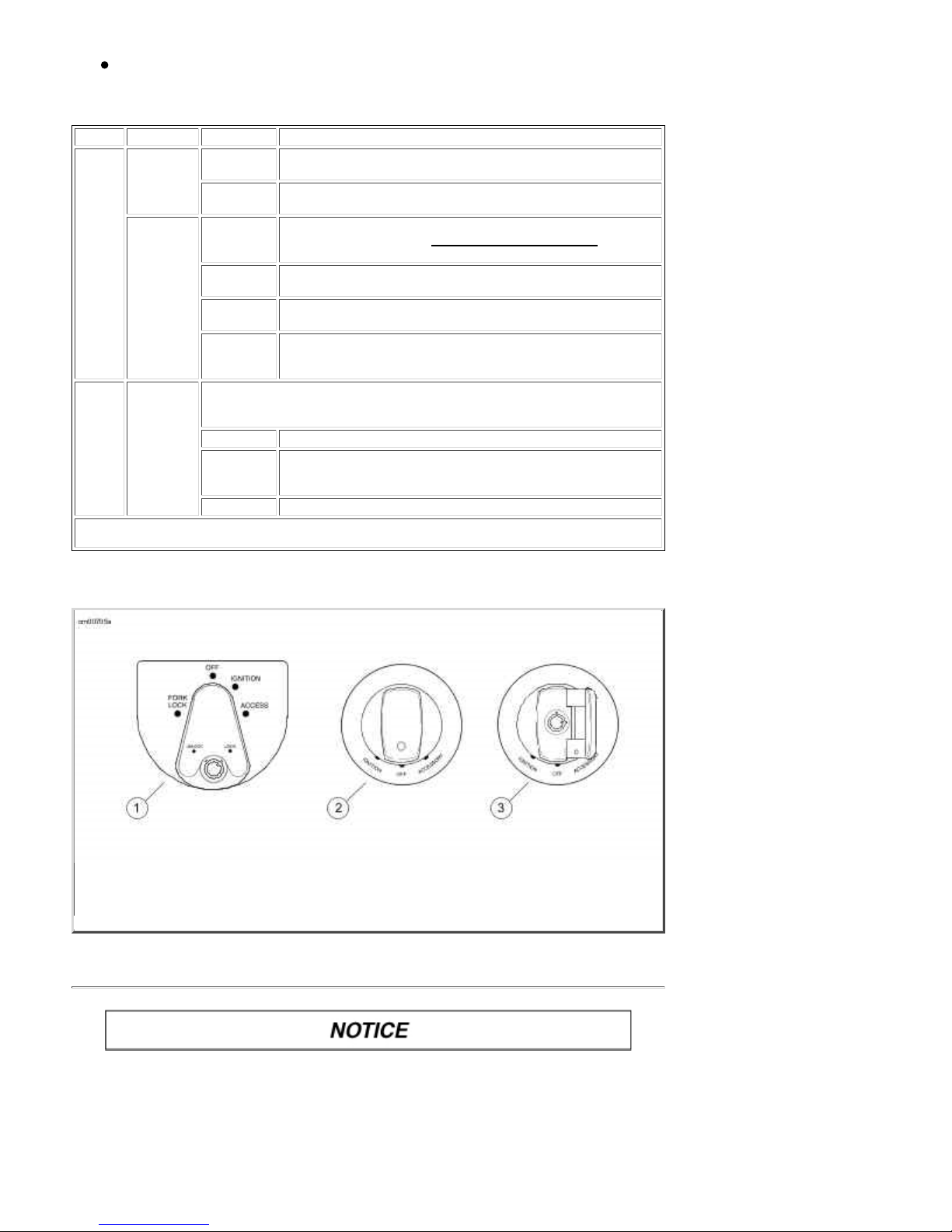
Ignition/Headlamp Switch Positions: Touring Models
MODEL FUNCTION LABEL OPERATION
FLHT
FLHTC
FLHTCU
FLTR
FLHX
FLHR
FLHRC
* International models have an additional function. Position lamp and tail lamp are also on.
Key L ock LOCK Locks the switch in e ith er the FORK LOCK or ACCESS switch
position. Remove the key for secur ity.
UNLOCK Unlocks the switch. U nlocked , the switch can be r otate d to any
of the 4 positions. To prevent loss when ridi ng, r emove the key.
Switch FORK LOCK Locks fork in left position to discourage unauthorized use of
vehicle when p a rked. See Fork Lock: Tourin g Model s for
operation.
OFF When switch is in OFF position, the ignition, lamps and
accessories are off .
I GNITION When th e switch i s in the IGNITION posi tion, th e motorcycle can
be started and all lamps and accessories will operate.
ACCESS When the switch is in the ACCESS positio n, all the lamps and
accessories will operate but the engine can not be started. In
ACCESS, the switch can be locked.
Switch Sw itch is locked or unlocked by lifting switch cover, inserting key and turning
key counterclockwi se to lock, clockwise to unlock. Key may be removed in
any position.
OFF Ignitio n, lamps and accessories are off.
ACCESSORY Accessories are on. Hazard warning flashers can be left on.
Instrument lamp s are on. Brake lamp and horn can be
activated.*
IGNITION Ign iti on, lamps and accessories ar e on.*
All except FLHR models1.
All FLHR models (co ver shown closed)2.
All FLHR models (co ver shown open)3.
Ignition/Headlamp Key Switch: Touring Models
Fork Lock : T ouring Models
Protect your vehicle agai nst theft. After parking your motorc ycle, lock the steering
head and remove ignition key from switch. Failure to lock your motorcycle may
result i n theft and/or equipment damage. (00151a)
Using the fork lock immediately after parking your motorcycle will discourage unauthorized use or
theft when parki ng your motorcycle.
2 of 27 07/30/2011 4:44 A
Page 19
2009 Touring Models Owner's Manual: Controls and Indicators https://www.harley-davidson.com/en_US/Content/Pages/Owners/om/200...
M
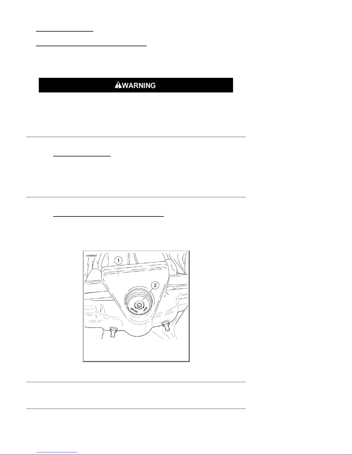
See Fork Lock: FLH R/FLHRC. On FLHR/FLH R C model s, the fork lock is located at the top of th e
steering head, behind the headlamp nacelle and inset in the handlebar clamp shroud.
See Ignition/Headlamp Key Switch: Touring Models. On FLHT/FLTR/FLHX models, the fork lock is
integrated into the ignition switch.
NOTE:
Do not force the switch into the lo cked position or switch d a mage can o c cur.
Do not operate veh icle with f orks locked. Locking th e forks restricts the vehicle's
turning ability, which could result in death or serious injury. (00035a)
To Lock Fork on FL HR/FL HRC Models
Turn fork to full left position.1.
See Fork Lock: FLH R/FLHRC. Inser t key an d turn key counterclockwise to LOCK position.
2.
Remove key.
To unlock fork, insert key and turn clockwise to UNLOCK position. Remove key.3.
To Lock Fork on FL HT/FL TR /FLHX M od els
Turn fork to full left position.1.
See Ignition/Headlamp Key Switch: Touring Models. Turn switch knob to FORK LOCK and
2.
push knob down.
I nsert key and turn key to LOCK p osi tion. R emove key.3.
To unlock fork, insert key and turn to UNLOCK position. Remove key and rotate switch knob
4.
out from the FORK LOCK position.
Cl amp s hroud1.
Fork lock2.
For k Lock: FLHR/FLHRC
Hand Controls: Basic Operation
Electric Starter Switch
NOTE:
Off/Run switch MUST be in RUN po sitio n to operate engine.
3 of 27 07/30/2011 4:44 A
Page 20
2009 Touring Models Owner's Manual: Controls and Indicators https://www.harley-davidson.com/en_US/Content/Pages/Owners/om/200...
M
See Basic Handlebar Controls: FLHRC Shown (typical). The electric starter switch is located on
the right handlebar control group. See Starting the Engine for detail ed operation procedures.
Put the engi ne off/run switch in the R UN position and the tr ansmission in neutral. Neutral
1.
(green) indicato r lamp should be illuminated.
See Ignition/Headlamp Key Switch: Touring Models. Turn i gn ition/headlamp key switch to
2.
I GNITION an d push th e START switch to operate starter motor.
Engi n e OFF/RU N S wi t ch
See Basic Handlebar Controls: FLHRC Shown (typical). The en gine off/r un switch (7) tu rns the
ignition power ON or OFF. The engine off/run switch is located on the right handlebar control. Push the
top portion of the engine off/run switch to turn off igni tion power and shut the engine off. Push the
bottom portion of the engine off/ru n switch to tur n on ignition power.
NOTES:
The engin e o ff/run swi tch must be in the RUN po siti o n to start or operate the en gine.
The engine off/run switch should be used to shut the engine off.
To shut the engi ne off, pu sh the top of the off/run switch to the ignition OFF position.1.
See Ignition/Headlamp Key Switch: Touring Models. T urn th e ign ition key to the OFF
2.
position to turn the ignition power completely OFF.
Throttle Control Grip
See Basic Handlebar Controls: FLHRC Shown (typical). The throttle co ntrol grip (9) is located on
the right h a n d lebar contr ol a n d is operated with the right h and.
To reduce r ider fatig ue on long tr ips, a sp ring l oaded throttle friction adjustment screw (10) i s located
at the bottom of the throttle grip clamp on non-cruise equipped models.
Sl owly turn th rottle control grip clockwise (toward the front of the bike) to close the throttle
1.
(decelerate).
Sl owly turn th rottle control grip coun terclockwise (toward rear of bike) to open the th rottle
2.
(accelerate).
Do not tighten throttle fri ction adjustment screw to the point where the engine
will not return to idle automatically. Over-tightening can lead to loss of vehicle
control, which could result in death or serious injury. (00031b)
Unscrew the th rottle fricti on ad j ustment screw so the throttle r eturns to the idle position when
3.
the hand is removed from the grip.
Screw the throttle adjustment screw in to increase friction on grip. This provides a damping
4.
effect on thr ottle motion.
NOTE:
The throttle friction adjustment screw sho u l d n o t b e u sed u n der nor mal stop an d g o op er ati ng
conditions.
Clutch Hand Lever
Do not position fingers between hand control lever and handlebar grip. Improper
hand positioning can impair control lever operation and cause loss of vehicle
control, which could result in death or serious injury. (00032a)
See Basic Handlebar Controls: FLHRC Shown (typical). The clutch hand lever (1) is located on the
4 of 27 07/30/2011 4:44 A
Page 21
2009 Touring Models Owner's Manual: Controls and Indicators https://www.harley-davidson.com/en_US/Content/Pages/Owners/om/200...
M
lef t handlebar and i s operated with th e f ing ers of the lef t hand.
Slowly pull clutch hand lever in against handlebar grip to fully disengage clutch.1.
Shift to first gear u sing the gear sh ifter lever. S ee Cruise Control: Touring Models.2.
Slowly release the clutch hand lever to engage clutch.3.
A clutch switch is incorporated into the left handlebar switch assembly. It enables the rider to start the
vehicle in any gear (or in neutral) as long as the clutch lever is pulled in. If the clutch is not disengaged,
the vehicle will not start.
Horn Switch
See Basic Handlebar Controls: FLHRC Shown (typical). The horn is operated by pushing on th e
horn switch (2) located on the left handlebar control group.
Headlamp Dimmer Switch
See Basic Handlebar Controls: FLHRC Shown (typical). The headlamp dimmer switch (3) is
located on the left h a ndl ebar. The switch h a s two positions to activate the head lamps h igh or low
beams.
Press the top of the h ea dlamp d immer beam switch to activate the h igh b ea m.
Press the b ottom of the headlamp dimmer switch to retur n to the low beam.
See Indicator Lamps. The (blue) high beam indicator lamp will illuminate when the high beam is on.
Turn Signal Switches
See Basic Handlebar Controls: FLHRC Shown (typical). Each handlebar control group contains a
tur n si gnal switch.
The r igh t turn signa l switch (11) operates the rig ht front and ri ght rear flash ing lamps.
The left turn sign al switch (4) operates the left front and left rear flashi n g lamps.
NOTE:
Front turn signal lamps also function as running lamps (except International models).
Cruise Cont r ol Switches
Electronic cruise control is standard for FLHRC, FLTR, and FLHTCU mo dels. For all other models, cruise
control is available as a factory-installed option.
See Cr ui se Control: Touring Models for detailed operation.
5 of 27 07/30/2011 4:44 A
Page 22

2009 Touring Models Owner's Manual: Controls and Indicators https://www.harley-davidson.com/en_US/Content/Pages/Owners/om/200...
M
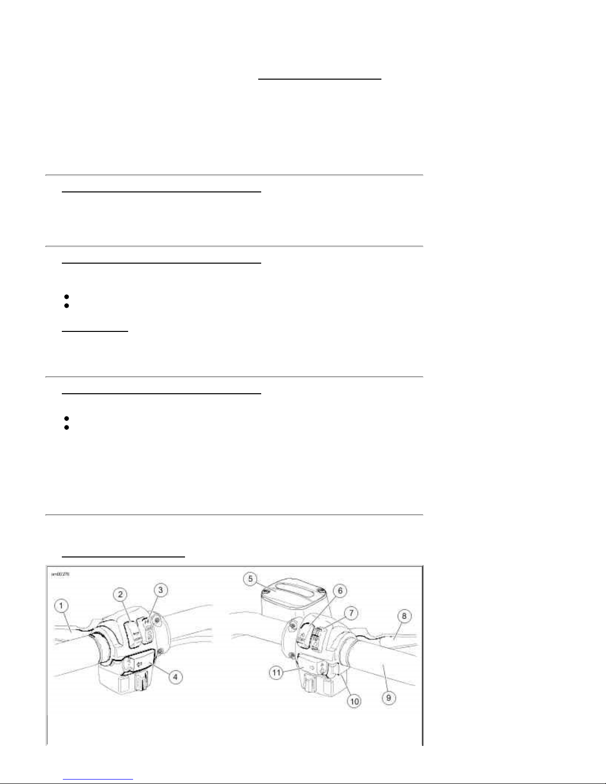
Clutch hand lever1.
Horn switch2.
Hea dlamp dimmer switch3.
Left turn signal switch4.
Master cyli nder reservoir5.
Electri c starter switch6.
Engine off/run switch7.
Brake hand lever8.
Throttle control gri p9.
Throttle friction adjusting screw (not shown, not used on cruise control models)10.
Right tu rn signal switch11.
Basic Handlebar Controls: FLHRC Shown (typical)
Electronic Throttle Con trol (ETC )
Tourin g models are equipped with Electronic Throttle Control (ETC). Instead of using a mechanical
cable connection to the throttle body, th is techn ology uses redundant g rip sensors to indicate rider
requ ested throttle position to the Electronic Module (E CM). T he ECM then r egul ates proper fuel/air
intake and ignition timing b ased on the ri der request. The gri p sensor is man ufactured with internal
cams and spring retainer for natural feel and operation.
ETC operation is designed for ri der safety and continued motorcycl e operation, even in the event of a
component f ailure. T h e E lectronic Contr ol Module monitors the status of the g r ip sensors, throttle
plate actuation and airflow. If any problems are detected, the motorcycle will disable cruise control,
illuminate the engine check lamp, and revert to one of the following fallback modes.
ETC Limited Performance Mode
The rider will experience near-normal operation. The motorcycle will operate with provisions to guard
against unintended acceleration.
ETC Power Managem e nt M ode
The throttle plate actuator returns to an "idle detent" or "limp-home" po sition, which will provide
enough torque to achieve speed of about 25 mph 40 kph . The motorcycle's response to grip sensor
input is significantly reduced.
ETC Forced Idle Mode
The throttle plate actuator is forced to a "fast idle" position, which will provide enough torque to crawl,
but n ot enoug h torque to operate at traffic speeds.
ETC Forced Shutdown Mode
The en gin e is forced to shut d own.
Turn Signal Switch Operation
The turn signal switches are used by the turn signal module to control turn signal operation based on
vehicle sp eed , vehicle acceleration and turn completion.
Momentarily depress the desired turn signal switch. The turn signal lamps will begin and continue
flashing until they are manually or automatically cancelled. As long as the motorcycle is stationary, the
signals will flash.
NOTES:
If you are signa l i ng to tur n in one direction and you depr ess the switch for the o pposite turn
signal, the first signal is cancelled and the opposite side begins flashing.
If you want to stop t he lamps fr o m flashing, briefly dep ress the t urn signal switch a sec o nd
time. The turn signal lamps will stop flashing.
6 of 27 07/30/2011 4:44 A
Page 23
2009 Touring Models Owner's Manual: Controls and Indicators https://www.harley-davidson.com/en_US/Content/Pages/Owners/om/200...
M
Hazard Warning 4-Way Flasher
Use the following method to activate th e f our -way flashers.
With the ignition key ON and security system disarmed (if equi pped), press the left and right
1.
tur n si gnal switches at the same time.
Turn the ignition key OFF and arm the security system if present and desired. The four-way
2.
flashers will continue for two hours.
To cancel four -way f lash ing, disar m th e security system if nece ssary, tu rn th e ignit ion key ON
3.
and press the left and right turn signal switches at the same time.
This system allows a stranded vehicle to be left in the four-way flashing mode and secured until help is
found.
Indicator Lam ps
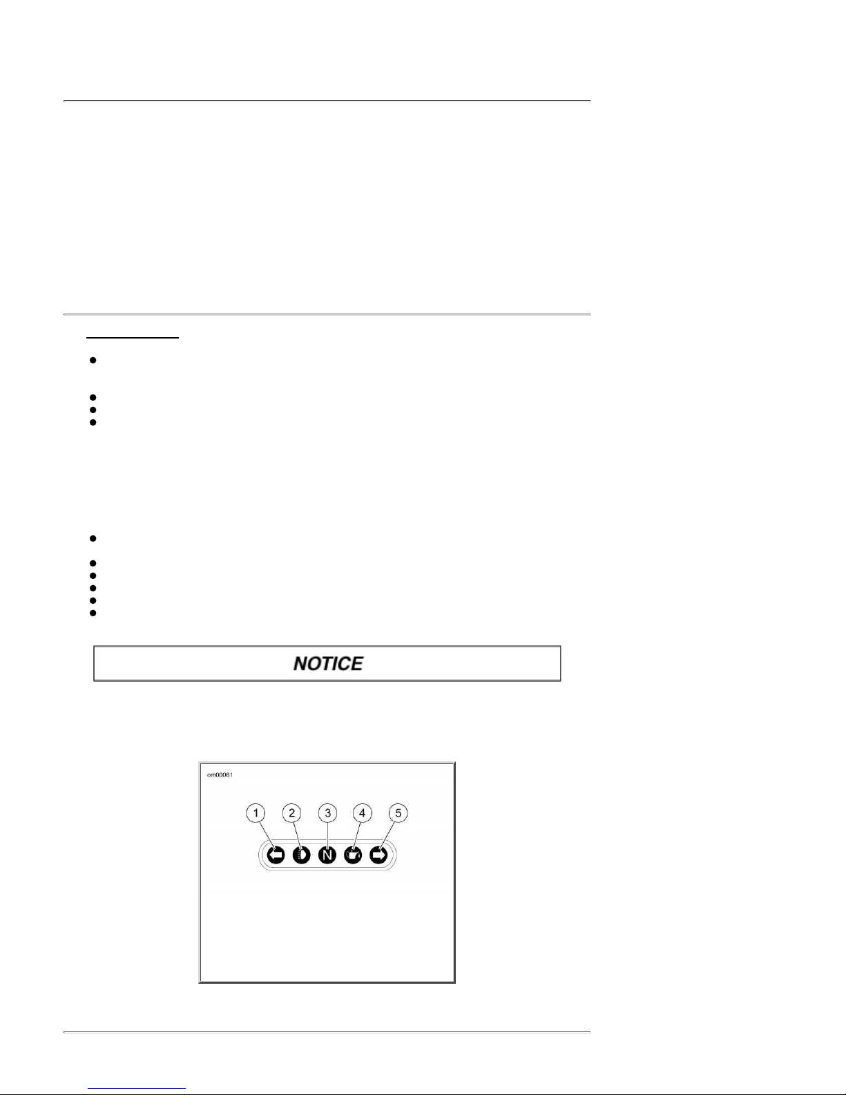
See Indicator Lamps. Five indicator lamps are provided.
The green TURN indicato rs will flash when turn signals are activated; therefo re, flashing
indi cates the chosen turn dir ection. When the 4-way hazard fl ashers are operating, both turn
indicators will flash simultaneously.
The blue BEAM indicator lamp, when lit, signals high beam headlamp operation.
The green NEUTRAL lamp, when lit, signals the transmission is in neutral gear.
The red OIL indicato r lamp, when lit, signals that oil is not circulating through the engine.
NOTE:
The OIL indicator lamp will glow wh en the ignition is turned on prior to startin g engin e. With engine
running, lamp should be off when engine speed is above idle.
Sever al other circumstances t hat coul d cause th e red oil indicator lamp to si gnal, include the foll owing:
If the oil pressure indicator lamp does not go off at speeds above idling, it is usually because of
an empty oil tank or diluted oil.
I n freezin g weather the oil feed may clog with ice and sludg e, preventing oil circulati on.
A grounded o il signal switch wire.
A faulty sign al swi tch.
A damaged or improperly installed check valve.
Trouble with the pump.
If the oil pressure indicator lamp remains lit, always check the oil supply first. If
the oil supply is normal and the lamp is still lit, stop the engine at once and do not
ride further un til the tro uble is located an d the n ecessary r epai rs are made. Failure
to do so m ay result in engine damage. (00157a)
Left turn1.
High beam2.
Neutral3.
Oil4.
Right tu rn5.
Indicator Lamps
Instruments: Touring Models
7 of 27 07/30/2011 4:44 A
Page 24

2009 Touring Models Owner's Manual: Controls and Indicators https://www.harley-davidson.com/en_US/Content/Pages/Owners/om/200...
M
Speedometer
Travel at sp eeds appropriate for road and co nditions and never tr avel faster than
posted speed limit. Excessive speed can cause loss of vehicle control, wh ich c ould
resu lt in death or se rious injury. (00008a)
See Indicator Lamps: Touring Models. The sp eedometer r egisters miles p er hour (U.S . models) or
kilometers per hour (inter national models) of forward speed. T he speedometer also provi d es the
following selectable functions:
Odometer
Trip odometers A and B
12 or 24 hour clock (if ra dio not inst alled)
Fuel range function
The speed ometer has a sing le displ a y window for the above functions. If an Ad vanced Aud io System is
installed, the radio will provide the clock function.
See Indicator Lamps: Touring Models. Pressing th e function switch wi th the ignition swi tch
1.
in any position will activate the odometer reading and time. Time and mileage/kilometers may
be ch e ck ed without un locki ng ignition switch. Press and release function switch once to vi e w
odometer. Pr e ss and re lease switch ag ain to display time.
To check mileage on trip odometers, the ignition swi tch mu st b e in the ACC or IGNITI ON
2.
position. Press and release the function switch until the desired trip odometer reading is
displayed. An A or B in the upper left of the display window identifies trip odometers.
To reset or zero trip odometers, have desired (A or B) odometer i n di splay window. Press
3.
function sw itch and hold switch for 2-3 seconds. The trip odometer will be reset to zero.
Repeat the previous step if you wi sh to zero both tri p odometers.4.
Setting Clock
I f the motorcycle is equ ipped with an A d vanced Audio System, see the A dvanced Au dio System
section in this manual to set the clock in the radio .
Tur n the ignition swi tch to ACC or IGNIT ION.1.
See Indicator Lamps: Touring Models. Press function switch until time (hour and minutes)
2.
is displayed. Press and hold the function switch for five seconds or until 12HR begins to blink in
the speedometer display window. Release the b utton.
Press and release the function switch once to advance to a blinking 24HR or military style time
3.
display. Each time you press and release the button, the display will switch between 12HR and
24HR.
When the de sire d time s ty le is displayed, pre ss a nd hold th e funct ion swi t ch for five second s.
4.
The display will switch to the time display with the hours blinking.
NOTE:
There is no AM or PM time setting required. So when correct hour is reached, press and hold
function switch to advance to minute setting.
Press and release th e f uncti on swi tch repeatedly to advance the h our s. Each time you press
5.
and release the switch, the display will advance one hour.
When the corre ct hour is displayed, pre ss a nd hold th e funct ion swi t ch for five second s. The
6.
minutes display will start blinking.
Press and release th e f uncti on swi tch repeatedly to advance the minutes display. Ea ch time
7.
yo u press and release the button, the display will advance one minute.
When the correct min utes are displayed, p ress and hold the functi on switch for five seconds.
8.
The minutes display will stop blinking, indicating that the clock has been set.
Tur n the ignition swi tch OFF.9.
8 of 27 07/30/2011 4:44 A
Page 25
2009 Touring Models Owner's Manual: Controls and Indicators https://www.harley-davidson.com/en_US/Content/Pages/Owners/om/200...
M
Tachometer
See OPERATING RECOMMENDATIONS section. Do not operate the engine above
maxi mum safe RPM as shown under OPERATION (red zone on tachometer).
Lower the RPM by upshifting to a higher gear or reducing the amount of throttle.
Failure to lower RPM may cause equipment damage. (00159a)
See Indicator Lamps: Touring Models. The tachometer measur es the engine speed in r evoluti ons
per minu te (RPM).
Tip Indicator Lamp
If tip occurs, check all c ontrols for proper operation. Restricted control movemen t
can adversely affect the performance o f the brak es, clutch or ability to shift, which
coul d resu lt in loss of vehicle control and death or serious injury. (00350a)
Should motorcycle be tipped over, the word "tip" will appear in the odometer window. Engine will not
start until r e set . To reset, cycle ignition/headla mp key switch ON -OFF-ON.
Fuel G auge
The fuel g auge i ndi cates the approxi mate amount of fuel in the fuel tank(s) and i s located to left of the
speedometer or on the left front pan el of the fairing.
NOTE:
The FLHR left side fuel cap i s a fuel gauge on l y. Do not remove.
Oil Press ure Gauge (FLHT/FLTR/FLHX)
The oil pressure gauge indicates engine oil pressure and is found on the front panel of the fairing.
Engine oil pressure will normally vary fro m 5 psi (34 kN/m2) at idle speed to 30-38 PSI (207-262
kN/m2) at 2000 RPM when engi ne is at n ormal operating temperature of 230° F (110° C).
Voltm e t er (FLHT/FLTR/FL HX)
The voltmeter indicates electrical system voltage and is found on the front panel of the fairing. With
the engine running above 1500 RPM, the voltmeter should register 13-14.5 volts with battery at full
charge.
Air Temperature Gauge (FLHT/FLTR/FLHX)
The air temperature gauge in dicates th e ambient air temper ature i n degrees Fahrenheit. This gauge i s
found on the front panel of the fairing.
Fuel Range Function
9 of 27 07/30/2011 4:44 A
Page 26
2009 Touring Models Owner's Manual: Controls and Indicators https://www.harley-davidson.com/en_US/Content/Pages/Owners/om/200...
M
The fuel r a nge fun ction shows the approximate mileag e availabl e with the amount of fu el l eft in the fuel
tank.
With the ignition swi tch in the ACC or IGNITION position, p ress function switch unti l fuel r ange
1.
function is displayed, as indicated by the letter 'r' in the left side of the odometer display. The
calculated remaining distance (miles or kilometers) to empty is displayed, based on the
amount of fuel in tank. Range can be accessed at any time using the function switch.
When the lo w fuel warning lamp illuminates, the range feature will automatically be displayed in
2.
the odometer unl ess this automatic pop-up feature is disabled by a press and hold of the
function sw itch while in range display mode. Automatic range pop-up feature will show that it
is disabled by bli n ki ng twice. Likewise, automatic range popup can be reactivated by a press
and ho ld of the function switch. Range will blink once when the automatic pop-up feature is
re-enabled.
NOTE:
After the range calculation reaches 10 miles 16 kilometers remaining, the range display will
3.
display "r Lo" to indicate that the vehicle will shortly run out of fuel.
Resetting the low fuel warning lamp and range requires an ignition cycle change.4.
When the low fuel war ning l amp turns on, ther e i s ap proximately 1.00 gallon 3. 79
liters of fuel remaining in the tank. Refuel as soon as p ossible.
The rang e display is on l y updated when th e vehicle is moving .
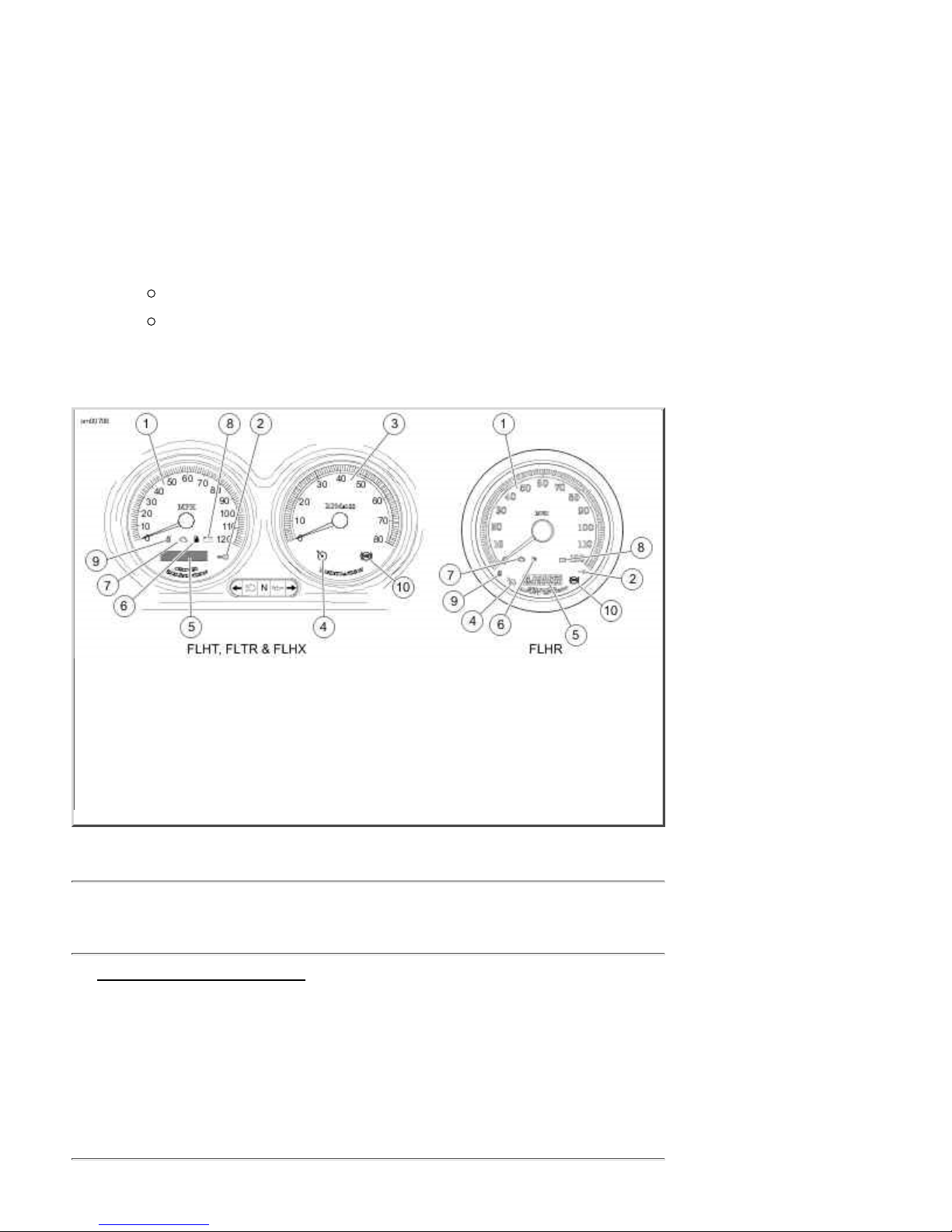
Speedometer1.
Secu r ity syste m lamp2.
Tachometer3.
Crui s e lamp4.
Odometer/trip-odometer/clock5.
Low fuel war nin g lamp6.
Engine check lamp7.
Battery discharge lamp8.
Sixth gear lamp9.
ABS lamp10.
Indic ator Lamps: Touring Models
Indicator Lamps: Touri n g Models
Engine Check La mp
See Indicator Lamps: Touring Models. The engine check lamp is located near the lower left side of
the speedometer (FLHT models) face or lower center of the speed ometer (FLHR model s) f a ce. Its
pur pose is to indicate whether or n ot the engi ne/engine managemen t system is operating normally.
The engine lamp color is amber.
The engine lamp normally comes on when the ignition is first turned on and remains on for
app r oximately 4 seconds, a s the eng ine managemen t syste m r uns a ser ies of self-diag nostics.
If the engine lamp comes on at any other time, see a Har ley-Davidson dealer.
Low Fuel Lamp
10 of 27 07/30/2011 4:44 A
Page 27
2009 Touring Models Owner's Manual: Controls and Indicators https://www.harley-davidson.com/en_US/Content/Pages/Owners/om/200...
M
See Indicator Lamps: Touring Models. The low fuel lamp is located in the speedometer face, lower
center by check engine lamp. The lo w fuel lamp illuminates to indicate that yo u have approximately 1
gallon 3.8 liters of gasoline left in the tank. The low fuel lamp color is amber.
Battery Discharg e La m p
See Indicator Lamps: Touring Models. The red battery charging l amp indicates either overcharging
or under charging of the ba tter y. Refer to Battery: General.
Cruise Control Equipped Models
See Indicator Lamps: Touring Models. Cruise control equipped models feature two additional
indicator lamps.
An orange lamp on the cruise control switch which indicates the cruise control is ON or OFF.
A green lamp on the tachometer (speedometer for FLHR models) face ind icates the crui se
control is SET or NOT SET.
NOTE:
Touring Models are either equip ped with cruise contr o l or are crui se control read y. See a Harl ey-
Davidson dealer for more information.
ABS Lamp
See Indicator Lamps: Touring Models. On ABS equipped models, the amber ABS indicator lamp
begins to flash at key ON to indicate that the system is operational. It continues to flash until
moto rcycle speed exceeds 3 mph 5 km/h . Continuo us illumination of the lamp will only occur when
ABS detects that the system is malfunctioning. In the diagnostic mode, the lamp will also illuminate to
indi cate the presence of diagnostic trouble codes (DTCs). See a Harl ey-Davidson dealer f or service.
If ABS lamp remains on continuously, the ABS is not operating. The standard
brake system is operational, but wheel lock up can occur. Contact a HarleyDavidson Dealer to have ABS repaired. A locked wheel will skid and can cause loss
of vehicle control, which could result in death or serious injury. (00361a)
Cruise Control: To uring Models
Operating Controls
The cruise control system pr ovides automatic vehi cle sp ee d control .
Do not use the cruise control system in hea vy traffic, on roads with sharp or blind
curves or on slippery roads of any kind. Using the cruise control in these
circumstances c an cause loss of control, which could resul t in death o r serious
i njury. (00083a)
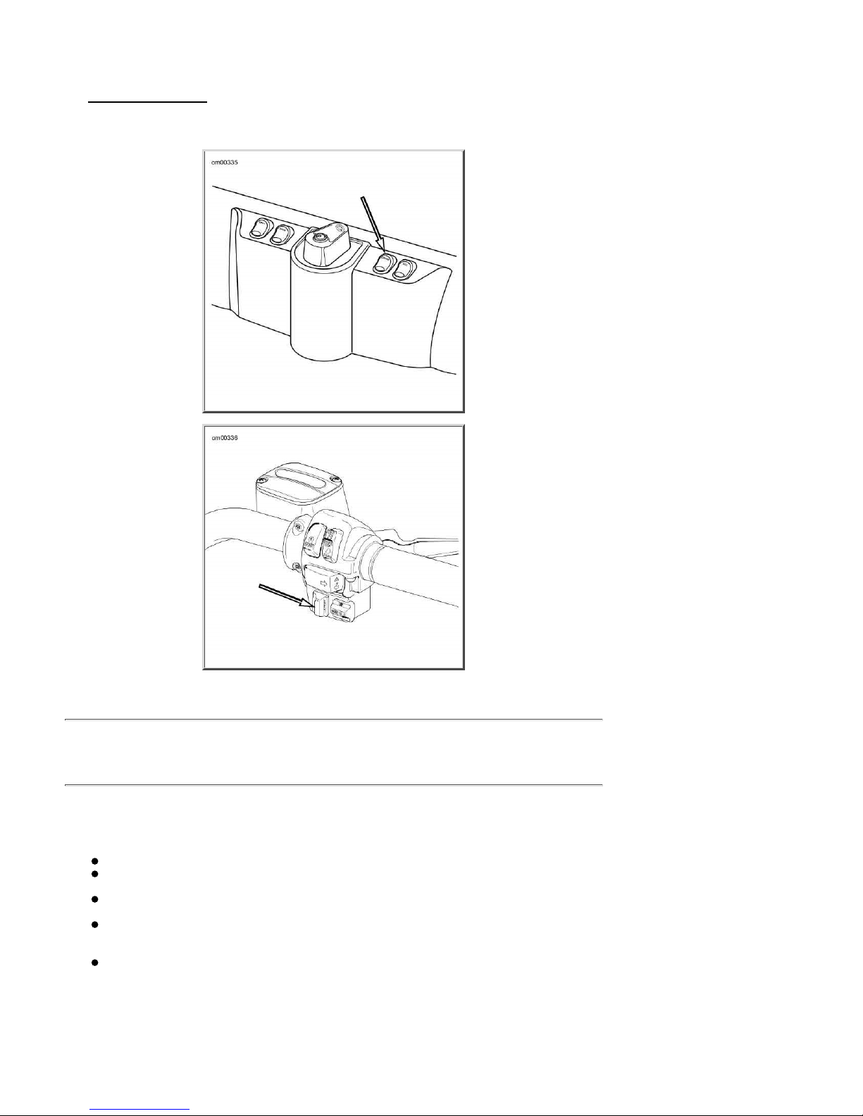
See Cr ui se Control Fairin g Cap Sw itch
igni tion/head lamp key swi tch turn s the cruise control system ON and OFF.
On FLHR models, the cruise control switch housing is on the left handlebar.
NOTE:
The cruise control icon o n the speedo meter o r tachometer wil l turn or ange to indicate the cru i se
11 of 27 07/30/2011 4:44 A
. A fai ring cap cruise control switch located to the right of the
Page 28
2009 Touring Models Owner's Manual: Controls and Indicators https://www.harley-davidson.com/en_US/Content/Pages/Owners/om/200...
M
control is ON . If the orange ico n does N OT come o n, the system is NOT ON. You cann o t SET cruise
speed, see you r dealer.
See RESUME/SET Switch. RESUME/SET switch located in the right handlebar control group.
The R ESUME/SET switch contr ols several system functions, including set, resume, acce lera t e a nd
decelerate.
Cruise Control Fairing Cap Switch
RESU ME/ SET Switch
Cruise Control Operation
Theory of Operation
The cruise control is designed to be safely operated with minimum movement by the rider and all rider
control actions are n atural and easy.
NOTES:
The rider al w ays o ver-rides and controls the system.
The system will not wo rk at vehi cle speeds below 30 mph 48 km/h o r above 85 mph 137
km/h .
The system is managed by th e ECM. The tachometer p rovides information to diseng age the
system if the engin e RPM suddenly i ncreases.
Besides th e ECM, th e system h as other compon ents: a stepper-moto r (controll ed by the
computer) w hich oper ates the throttle durin g CRUISE o peration, and several internal sw i tches,
all sending information to the computer.
The system will allow r ider to incr ease sp eed 10 mph 16 k m/h o r more (depen d i ng on h o w
hard the rid er rolls on the throttle and the condition o f the vehicle) over the S ET point before
deactivating . This feature allows the rider to momentarily increase sp eed, if necessary.
Rolling on the throttl e to greatly increase speed may deactivate the system.
Engaging Cruise Control
12 of 27 07/30/2011 4:44 A
Page 29

2009 Touring Models Owner's Manual: Controls and Indicators https://www.harley-davidson.com/en_US/Content/Pages/Owners/om/200...
M
See Indicator Lamps: Touring Models. Tu rn th e cruise control switch t o th e ON position.
1.
The orange icon on the cruise gauge face will light when activated.
With t he motorcy cle t ravelin g at the desi red cru ise speed of 30-85 mph 48-137 km/h ,
2.
momentar ily push the RES UME /S ET switch on th e rig ht hand lebar to SET. After a delay of
about 1-1/2 seconds, the icon will turn green on the face of the gauge to indicate the selected
cru ising speed is l ocked in .
Disengag ing Cruise Control
The cruise control automatically disengages whenever the cruise control module receives one of th e
following inputs:
Front and/or rear brake is applied.1.
Throttle is rolled back or closed, thereby actuating roll-off (disengage) switch.2.
Motorcycle clutch is disengag ed (module senses too great an i ncrease i n RPM).3.
Vehicle sp eed is out of the operating range.4.
NOTE:
Rolling on the throttl e mor e than 10 mph 16 km/h above the set speed may al so deactivate the
cru i se contro l .
When the cruise is diseng aged, the green cruise en gaged icon on the face of the gau ge changes to
orange. The orange cruise control system icon remains ON until the main switch is turned off.
However, should you decide to SET a cr uise speed, RESU ME la st se t s peed, ACCELERATE or
DE CE LERA TE, simply pr e ss the RE S U ME / S ET switch.
Resum i ng Cruise Speed
If the system is deactivated using one of the methods described under DEACTIVATING CRUISE
CONTROL, the system is still ON sho uld you decide to RESUME the set speed. To accomplish this,
si mp ly p ress the RESUME/SET switch t o RESUME .
NOTE:
The computer w i l l hold the SET speed in memory for the RESUME function. If the vehicl e sp eed drops
more than 15 mph 24 km/h below the S ET speed, speed can no longer be R ESUMED. If crui se
operatio n is still desired, pr ess the RESU ME /S ET switch to SE T to reset the cruise speed.
Accelerating Above Cruise Spee d
With the cru ise speed set, momentar ily press the R ESUME/SE T switch to RESUME to increase
1.
the spee d by 1 mph 1.6 km/h .
Pressing and holding the RESUME/SET switch at RESUME will cause the system to continue to
2.
increase speed in increments of approximately 1 mph 1.6 km/h until the switch is released.
There is a delay of about 2 second s b ef ore th e speed i ncreases.
Decelerating Cruis e Control
With the cru ise speed set, momentar ily press the RESUME/SET switch to SE T to red uce the
1.
speed by 1 mph 1.6 kph .
Pressing and holding the RESUME/SET switch at SET will cause the system to continue to
2.
reduce speed in increments o f approximately 1 mph 1.6 kph until the switch is released. There
i s a del a y of about 2 seconds b e fore the sp e e d decre a se s.
Deactivati ng Crui se Control
13 of 27 07/30/2011 4:44 A
Page 30
2009 Touring Models Owner's Manual: Controls and Indicators https://www.harley-davidson.com/en_US/Content/Pages/Owners/om/200...
M
Turn crui se cont rol swi tch to the OFF position . The ora nge icon in th e gaug e is extinguished t o indicate
the system is OFF.
NOTES:
System will NOT work if:
Ri der operates at veh icle s peed s belo w 30 mph 48 km/h or abo ve 85 mph 137 km/h .
Brake lamps are on con stantly. See dealer .
Gear Shift Lever: Touring Models
Location
The clutch must be fully disengaged before attempting a gear shift. Failure to fully
disengag e the clutc h can result in equipment damage. (00182a)
The gear shift lever is located on the left side of the motorcycle and is operated with the left foo t. The
gear sh ift lever sh ifts the six-speed transmission from one gear to the ne xt.
Shift Pattern
See Shift Pattern: 6-Speed Touring Models. The shift pattern is sequential with first gear down and
five gears up.
The transmission is shifted into first gear from neutral by pressing the shift lever down until it clicks into
gear.
Neutral is located between first and second gear. The green neutral indicator lamp on the dash will
illuminate when the transmission is in neutral.
To shift from first gear to neutral, lift the gear shift lever 1/2 of its full stroke.
To upshift to the next higher gear, lift the gear shift lever up until it clicks into gear.
To downshift to the next lower gear, press the gear shift lever down until it clicks into gear.
NOTES:
Release th e foot sh ift lever a fter each gear chan g e . This allows th e l ever to return to its central
position before another gear change can be made.
Hee l -Toe Foot Sh i f t er
See Shift Pattern: 6-Speed Touring Models. Touring Models are fitted with a heel-toe shifter lever.
Two shift levers are fitted to the shifter shaft - one facing forward and one r earward.
The toe of the left foot can upshift or downshift using th e front shift l ever. However, the r ider has the
option of upshifting with the heel on the rear facing sh ift lever.
14 of 27 07/30/2011 4:44 A
Page 31

2009 Touring Models Owner's Manual: Controls and Indicators https://www.harley-davidson.com/en_US/Content/Pages/Owners/om/200...
M
Shift Pattern: 6-Speed Touring Models
Shifting While Stopped
When diffic u lty of shifting gears is experienced, do not under any circumstances,
attempt to force the sh ift. The results of such abuse will be a damaged or broken
shifter mechanism. (00161a)
When the motorcycle is standing still in first gear with the engine off or in neutral with the engine
running, the transmission may not shift gears. Because the rear wheel and drive belt are not turning,
the transmission gear teeth and engagement dogs can not line up.
To get one gear to disengage and the next gear to engage, pull the clutch lever in and move the
moto rcycle backward and forward while maintaining slight pressure on the shift lever.
See Shifting Gears for more information.
Brake System
General
The rear brake pedal controls the rear wheel brake and is located on the motorcycle's right side.
Operate the rear brake pedal with the r igh t foot.
The front brake hand l ever controls the fr ont wheel brake and i s located on the right handlebar.
Operate th e hand lever with the fingers of the ri ght han d.
Do not position fingers between hand control lever and handlebar grip. Improper
hand positioning can impair control lever operation and cause loss of vehicle
control, which could result in death or serious injury. (00032a)
Some models are equipped with an anti-lock braking system.
Non-ABS Brake System
Apply brakes uni formly and evenly to prevent wheels from l ocki ng. Use front and rear brakes equally
15 of 27 07/30/2011 4:44 A
Page 32

2009 Touring Models Owner's Manual: Controls and Indicators https://www.harley-davidson.com/en_US/Content/Pages/Owners/om/200...
M
for best results.
Do n ot apply brake strongly enoug h to lock the wheel. A locked w heel will skid and
can cause loss of vehicle control, which could result in death or serious injury.
(00053a)
Ant i-lock Brake S yste m (ABS)
Harley-Davidson's Anti-Lo ck Brake System assists the rider in maintaining contro l when braking in a
strai ght-l ine emergency situation. A BS operates independentl y on f ront and rear brakes to keep the
wheels rolling and prevent uncontro lled wheel lock-ups either on dry pavement or on slick surfaces
such as gravel, leaves or when riding in wet co nditions.
ABS: How It Works
The AB S monitors sensors at the front an d rear wheels to determine wheel speed. If th e system
detects one or both wheels are slowing down too quickly, which indicates they are close to locking, or
if the decel eration r ate does not match a criteria stored in memory, the ABS reacts. The system
rapidly opens and closes valves to modulate the brake caliper pressure utilizing only the brake
lever/pedal pressure being applied by the rider. During ABS activation, the system provides the
electronic equivalent of manually pumping the brakes and is capable of cycli n g u p to seven times per
second.
The rider will recognize ABS activation by the slight pulsing sensation in the hand lever or the rear
brake pedal. The pulsi n g sensation may also be accompanied by a clicking sound from the ABS
module. Both are the resu lt of normal operation. Refer to ABS Symp t oms and Cond itio ns.
ABS: How To Use
Whi le an ad van tage in emergency braking, ABS i s n ot a substitute for safe riding. The safest way to
stop a motorcycle is upr ight with both wheel s str aigh t.
Harley-Davidson ABS is a manual assist system. When in an emergency stopping situation, maintain
pressur e on th e b r akes th rough al l ABS even ts. Do not modulate or "pump" the b r ake control s. T he
wheels won't l ock un til the end of the stop when motorcycle speed reaches appr oxi mately four miles
per hour and ABS is no longer needed.
ABS cannot prevent lockup of rear wheel due to engine braking. ABS will n ot aid in
cornering or on loose/uneven surfaces. A locked wheel will skid and can cause loss
of vehicle control, which could result in death or serious injury. (00362a)
More information is available at www.harley-davidson.co m/abs.
ABS: Tires and Wheels
ABS motorcycles must al ways use tires an d wheels that ar e the same as the orig inal equipment. The
ABS monitors the rotational sp eed of the wheels through indivi dual wheel speed sensors. Changing to
different d iameter wheels or dif f erent si zed tires can alter the rotational speed. This can u pset the
calibration of the ABS and have an adverse effect on its ability to detect and prevent uncontrolled
wheel lo ckups. Tire inflation pressure that is significantly low also can have an adverse effect.
ABS Symptoms and Conditions
SYMPTOM CONDITION
Pulsing brake
lever or pedal
during an ABS
16 of 27 07/30/2011 4:44 A
Normal conditio n.
Page 33

2009 Touring Models Owner's Manual: Controls and Indicators https://www.harley-davidson.com/en_US/Content/Pages/Owners/om/200...
M
SYMPTOM CONDITION
event
Clicking sound
during an ABS
event
ABS lamp flashing Normal condition - key turned to IGNITION - speed under 3 mph 5 km/h .
Perceived "surge"
while braking
Temporarily stiff
rear brake pedal
Tire chirp Normal condition - depending on surface, tire can chirp without locking the wheel.
Black mark on
pavement
Wheel lock at low
speed
Normal conditio n.
Normal conditio n - most noticeable when braking with one brake (front only or
rear only). Result of a reduction in deceleration which can be caused by cracks or
bumps in road, engine braking (high engine RPMs causing the rear wheel to slow
down), hard braking at slow speeds, and other conditions. This is due to ABS
modulating caliper brake pressur e to pr event uncontrol led wheel l ock.
Normal condition - engine braking (high engine RPMs causing the rear wheel to
slow down) or down shifting can activate A BS. If app lying th e rear bra ke at the
same time or i mmediatel y af ter, the ABS may be cl osi ng a val ve to pr event
pressure to the rear br ake. This is d ue to ABS modulating caliper br ake pressure
to prevent uncontrolled wheel lock.
Normal condi tion - depending on surface, tire can leave a black mark with out
locki ng the wheel.
Normal condition - ABS will not activate on front wheel belo w 3 mph 5 km/h or
on rea r wheel below 5 mph 8 km/h .
Jiffy Stand
Always park motorcycle on a level, firm surface. An unbalanced motorcycle can fall
over, which could result in death or serious injury. (00039a)
The jiffy stand is located on the left side of the motorcycle and swings outward to support the
motorcycle for parking.
The jiffy stand loc k s when placed in the full forward (do wn) position with vehicle
weight on it. If the jiffy stand is not in the full forward (down) position with vehicle
weight on it, the vehicle can fall over which could result in death or serious injury.
(00006a)
Be sure jiffy stand is fully retracted before riding. If jiffy stand is not fully
retracted, it can contact the road surface causing a loss of vehicle control, which
coul d resu lt in de ath or serious injury. (00007a)
Jiffy Stand Interlock: International Models
Some international mo dels are equipped with a jiffy stand interlock feature.
I f the rider attempts to start the engi ne or pushes the starter button while the tra nsmissi on is i n gear
and the jiffy stand is down, then the jiffy stand interlock system will not permit the engine to run. The
message "SidE StAnd" will scroll across the odometer to indicate this to the rider. Raising the jiffy
stand (or putting the transmission in neutral) will permit the engine to run and clear the message.
I f the ji ffy stand f alls out of the fully retracted posi tion whi le riding at sp eeds greater than 10 mph 15
km/h , then the jiffy stand interlock system will maintain engine operation and alert the rider about this
by illuminating the indicators (flash twice) and scroll the message "SidE StAnd" across the odometer.
The message will remain until the system detects the jiffy stand in the fully retracted position again.
The r ider may continue to operate the veh icle while i n this mode.
17 of 27 07/30/2011 4:44 A
Page 34

2009 Touring Models Owner's Manual: Controls and Indicators https://www.harley-davidson.com/en_US/Content/Pages/Owners/om/200...
M
The rider may clear t he text messages at an y t ime by pressing the fu ncti on switch once while the
vehicle is powered up.
NOTE:
If the operation o f raising the ji ffy stand and puttin g the transmission in gear i s rapidly execu ted, the
jiffy stand bou ncing off the frame could cause the jiffy stand interlock system to activate and stop
the eng i ne.
Rear View Mirrors
Objects in mirrors ar e closer than they appear. Use caution when ju dgi ng distanc e
of objects in mirrors. Failure to judge correct distances could result in death or
ser ious injury. (00033a)
Your vehicle is equipped with two convex rear view mirrors.
This type of mirror is designed to give a much wider view to the rear than a flat mirror. However, cars
and other objects seen in this type of mirror will look smaller and farther away than they actually are.
Use caution when judg ing the size or rela tive distance of objects seen i n rear view mirrors.
Always adjust the rear view mirrors to clearly reflect the area behind the motorcycle before
ridi ng.
NOTE:
Adjust mirrors so you can see a small portion of your shoulders in each mirror. This will help you
establish the relative di stance of vehicles to the rear of your motorcycle.
Fuel Filler Cap: Touring Models
To open, turn fuel filler cap counterclockwise and lift up. To close, turn fuel filler cap clockwise until it
clicks. The ratchet action of the cap prevents overtig htening.
Remove the fuel filler cap slowly. Fill fuel tank slowly to prevent fuel spillage. Do not fill above the
bottom of the filler neck insert. Leave enough air space to allow for fuel expansio n. Expansion can
cause an overfilled tank to overflo w fuel through the filler cap vent onto surrounding areas. After
refueling, be sure filler cap is securely tightened. Gasoline is extremely flammable and highly explosive.
I nadequ ate safety precau tions could result in death or serious in jury.
NOTES:
FLHT/FLTR model fuel filler cap is located beneath a locking door . Use the ignition key to
unlo ck fuel door . The fuel filler cap sho uld be full y clo sed before closing the fuel door.
See Fuel Tank: FLHR. FLHR model fuel filler cap is l o cated o n the right side of the fuel ta nk.
The cap on the left side is the fuel gauge and is not removable.
See SAFE OPERATING RUL ES and review safety pr ocedures listed below.
18 of 27 07/30/2011 4:44 A
Page 35

2009 Touring Models Owner's Manual: Controls and Indicators https://www.harley-davidson.com/en_US/Content/Pages/Owners/om/200...
M
Fuel g auge1.
Fuel filler cap2.
Function switch3.
Fue l Ta nk: FLHR
Do not spi ll fuel onto the motorc ycle while refueling. Immediately wip e up fuel
spills on your motorcycle. Fuel can cause damage to cosmetic surfaces. (00147b)
Use only un leaded fuel in catalytic converter-equipped motorcycles. Using leaded
fuel will damage the emission control system. (00150b)
Do not store motorcycle with gasolin e in ta nk within the ho me or garage w here
open flames, p ilot lights, sparks or electric motors are presen t. Gasoline is
extremely flammable and highly explosive, which could result in death or serious
i njury. (00003a)
Avoid spills. Slowly remove filler cap. Do not fill above bottom of filler neck insert,
leaving air space for fuel expansion. Secure filler cap after refueling. Gasoline is
extremely flammable and highly explosive, which could result in death or serious
i njury. (00028a)
Do not use aftermark e t fuel caps. Afterma rket fu e l caps may fit improperly and
leak, which could lead to death or serious injury. See a Harley-Davidson dealer for
approved fue l caps. (00034a)
Rear Air Suspension
General
See Rear Air Suspension Air Valve. A ll models feature air-adjustab le rear suspension. A ir pressure i n
the rear shocks may be adj usted to suit load requ irements, riding style and personal comfort.
For FLH R/C, FL HX and FLTR mode ls, refer to Rear Susp e nsion Recommended Air
Pres sur e : FLHR/C , FLTR, FLHX.
For FLHT/C/U models, refer to Rear Suspension Recommended Air Pressure: FLHT/C/U.
NOTE:
These are recommended starting points. Adjust to suit load conditions, riding style and comfort
desired. Less init i a l pressu re does n o t necessari l y r e sult in a so fter ride. Us ing pressur es outside the
recommended load ing rang e w i l l r esult in a reduction of available suspen sion travel and reduced rider
comfort.
Rear Suspension Recommended Ai r Pressure: FLHR/C, FLTR, FLHX
SHO CK LOAD TOTAL W EIG HT PRESSU R E
LB. KG PSI kPa
19 of 27 07/30/2011 4:44 A
Page 36

2009 Touring Models Owner's Manual: Controls and Indicators https://www.harley-davidson.com/en_US/Content/Pages/Owners/om/200...
M
SHO CK LOAD TOTAL W EIG HT PRESSU R E
LB. KG PSI kPa
Solo rider up to 150 up to 68 0 0
150-200 68-91 0-10 0-69
200-250 91-113 10-20 69-138
250-300 113-136 20-30 138-206
over 300 over 136 30-50 206-345
Solo rider wit h capacity lu ggage of 40 lbs 18 kg up to 150 up to 68 10-20 69-138
150-200 68-91 20-30 138-206
200-250 91-113 30-40 206-276
250-300 113-136 40-50 276-345
over 300 over 136 50 345
Rider plu s passenger ALL ALL 40-50 276-345
Maximum GVWR AL L ALL 50 345
If P&A Tour-Pak is installed, add 5-10 psi 34-69 kPa to shock pressure.
Do not exceed 50 psi 345 kPa rear shock pressure.
Rear Suspension Recommended Ai r Pressure: FLHT/C/U
SHO CK LOAD TOTAL W EIG HT PRESSU R E
LB. KG PSI kPa
Solo rider up to 150 up to 68 5-10 34-69
150-200 68-91 10-20 69-138
200-250 91-113 20-30 138-206
250-300 113-136 30-40 206-276
over 300 over 136 40-50 276-345
Solo rider wit h capacity lu ggage of 70 lbs 32 kg up to 150 up to 68 25-30 172-206
150-200 68-91 30-40 206-276
200-250 91-113 40-50 276-345
over 250 over 113 50 345
Rider plu s passenger ALL ALL 50 345
Maximum GVWR AL L ALL 50 345
Do not exceed 50 psi 345 kPa rear shock pressure.
Adjusting Shock Pressure
Do not exc e e d maxi mum air pressure for rear suspension. Air components fill
rapidly. Theref ore, use low air l ine p ressure. Failure to do so may resu lt in possibl e
damage to components. (00165a)
Use caution when bleeding air fro m the suspension. Moisture combined with
lubricant may leak onto the rear wheel , tire and/or brake components and
adversely affect traction, which could result in death or serious injury. (00084a)
See Rear Air Suspension Air Valve. To adjust the rear shock air pressure, use an air pump to fill or
release air from the air valve l ocated behin d the shock on the l eft side of th e vehicle.
20 of 27 07/30/2011 4:44 A
Page 37

2009 Touring Models Owner's Manual: Controls and Indicators https://www.harley-davidson.com/en_US/Content/Pages/Owners/om/200...
M
NOTES:
An AIR SUS PENSION PUMP AND GAUGE HD-34633 is available at your Harley-Davidson
dealer.
Do not e x c e ed maximum GVWR or GAWR .
Always clear the line by adding 3-5 psi 21-35 kPa before releasing air from the pump's valve,
but do not exceed 50 psi 345 kPa .
Rear Air Suspe nsi on Air Valve
Luggage
Do n ot exceed the motorcycle's Gro ss Vehi cle Wei ght Rating (GVWR) or Gr oss
Axle Weight Rating (GAWR). Exceeding these weight ratings can affect stability
and handling, which could result in death or serious injury. (00016e)
GVWR is the sum of the weight of the motorcycle, accessori es, and th e maximum weight of the rider,
passen ger and carg o th at can be saf ely car rie d .
GAWR is the maximum amount of weight that can be safely carri ed on each axle.
The GVWR and GAWR is shown on th e information plate, located on the frame steering head.
Make sure al l storage compartments are secure before operating motorcycl e.
Adhere to the weight limits and loading instructions on the labels within the storage compartments.
Tour-Pak
Operation
See Tour-Pak Lock and Draw Catch. Unlock lock and open draw catches.
Removal/Installation
Do NOT pull on any electrical wires. Pulling on electrical wires may damage the
internal conductor causing high resistance, which may result in minor or moderate
i njury. (00168a)
The Tour -Pak can be l ocated in two posi tions. See th e service manual or a Har ley-Davidson dealer
about Tour-Pak removal/r elocation.
21 of 27 07/30/2011 4:44 A
Page 38

2009 Touring Models Owner's Manual: Controls and Indicators https://www.harley-davidson.com/en_US/Content/Pages/Owners/om/200...
M
Tour-Pak Lock and Draw
Catch
Key1.
Lock2.
Draw catch3.
Tour - Pak Loc k and Draw Catch
Saddle b ags: FLHR /FLHT/FLHX/FLT R
Opening
See Saddlebags: FLHR/FLHT/FLHX/FLTR. Unlock latch.1.
Place fingers under latch and lift.2.
Place one hand at OUTSIDE CORNER of cover and other hand at opposite outside corner.3.
Lift outside edge of cover, pivoting in si de edge of cover in brackets.4.
Lift insi de edge of cover to disengage brackets.5.
Bring cover towards you, over saddlebag.6.
As you bring cover toward you, let it flip over, so the inside faces up. Let co ver rest against
7.
rub bars and nylon check strap.
NOTE:
The saddlebag lids are designed to stay attached to the bag s at al l times.
Closing
See Saddlebags: FLHR/FLHT/FLHX/FLTR. Use both hands to hold OUTSIDE corners of
1.
cover up and slide inside edge back into place so brackets slide together.
Close lid and secure latch. Brackets will engage automatically.2.
NOTE:
Saddlebag latch an d Tour-Pak d raw catches shou l d be closed and locked whenever motorcycle is in
operation.
Removing
See Saddlebags: FLHR/FLHT/FLHX/FLTR. The saddlebags are secured to the support brackets by
1/4 turn fasteners called bail head stud s.
NOTE:
If your vehicle (international only) does not have the wire form "bail", use a flat bladed screwdriver to
turn the studs.
22 of 27 07/30/2011 4:44 A
Page 39

2009 Touring Models Owner's Manual: Controls and Indicators https://www.harley-davidson.com/en_US/Content/Pages/Owners/om/200...
M
Unscrew saddlebag fasteners by t urnin g 1/4 turn counter clockwise.1.
Remove saddlebag.2.
Installing
Carefully place saddlebag in position on saddlebag rail and align the bail head studs with the support
bracket fasten ers.
See Saddlebags: FLHR/FLHT/FLHX/FLTR. Fasten studs by pushing i n to support bracket
1.
fasteners and tur ning 1/4 turn clockwi se.
Check that stud s are securely fastened.2.
Adjustments
If the latches become loose, you can adjust the latch fingers.
Adju st the latch fingers only enough to enable them to pr operly engage the latch
hinge. Bending latch fingers back and forth can overstress the metal and weaken
the fingers. ( 00169a)
Bend the fi ngers until they f irmly engage the hinge.1.
See Miscellaneous Lubrication for lubrication details.2.
Hinge1.
Latch2.
Anchor tabs3.
Bail head studs4.
Anchor brackets5.
Saddlebags: FLHR/FLHT /FLHX/FLTR
Saddlebag s: FLHRC
Opening
See Saddlebag Quick Disconnect. T o use th e qui ck disconnect str ap feature, lift up the strap end to
expose the quick release buckle and press on the lock tabs as shown.
The straps may also be opened and closed using the buckle in a conven tional man ner.
Closing
23 of 27 07/30/2011 4:44 A
Page 40

2009 Touring Models Owner's Manual: Controls and Indicators https://www.harley-davidson.com/en_US/Content/Pages/Owners/om/200...
M
Insert the male strap end into the receptacle on the bag and push until a positi ve "click" is felt.
NOTE:
See Leather Care for proper saddlebag care.
Saddlebag Quick Disconnect
Windshield: FLHR/C
Removal
See Windshield: FLHR/C. Insert your fingers into the wire form latch springs at either side of
1.
the windshield and move the TOP of the windshield assembly forward, until the TOP bracket
notches sl ide away from the grommets.
Carefull y lift the windshiel d bracket BOTT OM n otches off the bottom grommets.2.
Remove windshield.3.
NOTE:
For pro p er wind shield maintenance, see Windshields.
Installation
See Windshield: FLHR/C. Insert your fingers into the wire form latch springs at either side of
1.
the windshield and slide the BOTTOM windshield bracket notches onto the bottom grommets.
Sl ide the TOP bracket notches onto the top grommets.2.
Wire form latch spring1.
Grommet2.
Windshield3.
Clutch cable4.
Windshield: FLHR/C
24 of 27 07/30/2011 4:44 A
Page 41

2009 Touring Models Owner's Manual: Controls and Indicators https://www.harley-davidson.com/en_US/Content/Pages/Owners/om/200...
M
Adjus table Air Deflectors : FLHTCU
See Adjustable Air Deflector: FLHTCU Models. Air deflectors, located along the left and right
bottom edge of fairing, may be adjusted to direct airflow for rider and passenger comfort.
To adjust, grasp the outer edge of the deflector and pivot to desired position.
Adjustable Ai r De flector: FLHTCU Models
Cigarette Lighter: FLHX, FLHT/C/U, FLTR
See Cigar ette Lighter. FLHX, FLHT/C/U and FLTR models are equipped with a cigarette lighter. The
lighter is located on the left side of the fairing. To operate, press lighter into socket. The lighter will pop
out when hot.
The lighter is not in tended to be used as a p ower port for electri cal devices. Damage to the li ghter
recep ta cle may occur .
Cigarette Lighter
Accessory Switch
See Swi tch Indic ators. All touring models have an accessory switch (4) fo r the owner's use. This
switch is located on the right side of the fairing (FLHT) or left side triple clamp shroud (FLHR).
See Accessory Connector
be activated with the A CC switch. See a H ar ley-Davidson dealer for possible uses.
It is possible to overload your motorcycle's charging system by adding too many
electri cal accessories. If your combined electrical accessories operating at any one
time consu me more electrical current than your vehicle's charging system ca n
25 of 27 07/30/2011 4:44 A
. Th ere is an accessory connector located in front of the battery that can
Page 42

2009 Touring Models Owner's Manual: Controls and Indicators https://www.harley-davidson.com/en_US/Content/Pages/Owners/om/200...
M
produce, the electrical con sumption can di scharge the battery and cause veh icle
electri cal system damage. See a Harley-Davidson dealer f or advice about the
amount of current consumed by additional electrical accessories, or for necessary
wiring changes. (00211b)
Auxiliary (SPOT)1.
Speakers2.
Cruise control3.
ACC switc h (A CCESSOR Y)4.
Switch Indicators
Accessory Connector
Auxiliary Lamps: FLHT and FLHR/C
See Swi tch Indic ators. Use the auxiliary lamp switch (1) to turn ON the auxiliary lamps as required.
NOTES:
On the FLHT/C/CU, the auxiliary lamp switch (SPOT) is on the left side of the
ign ition /headl a mp key switch on fairing cap.
On the FLHR/C the a uxiliary lamp sw i tch (SPOT) is on the r ight side of the triple clamp
shroud.
The auxiliary lamps (SPOT) do not work w h en the h eadlamp is on high b eam.
Fairing Lower Vents: FLHTCU
See Fairing Lower Vent Control. Vents in fairing lowers are controlled by the lever shown. Adjust
vent openings to control air fl ow.
26 of 27 07/30/2011 4:44 A
Page 43

2009 Touring Models Owner's Manual: Controls and Indicators https://www.harley-davidson.com/en_US/Content/Pages/Owners/om/200...
M
Fairing Lower Vent Control
Rider Footboards
Ri der footboards are ad justable. See a Harley-Davi d son dealer for adjustment.
Passen ger Foot boards/Footrests
Passen ger footboards/ footrests ca n be adjusted to one of three p ositi ons. Before moving to a new
position, remove plastic plugs from holes in the footrest mount in the frame as necessary.
See Passenger Footboar d/Footr e st (typical) Remove socket screw wit h lockwashe r to
1.
remove footboard/footrest bracket from footrest mount in fr ame.
Insert pin on footboard bracket into mount hole at the desired position.2.
I nstall socket screw with lockwasher . Tighte n socket screw to 30-35 ft-lb s (41-47 Nm).3.
Sc rew wit h lockwasher1.
Pin2.
Footrest/footboard mount on frame3.
Passeng e r Footboard/Footrest (typi cal)
27 of 27 07/30/2011 4:44 A
Page 44

2009 Touring Models Owner's Manual: Advanced Audio Syste
m
M
Advanced Audio System
Advanced Audio System
The Advanced Audio System by Harman/Kardon® is based on an electronic unit mounted inside the
front fairing of selected Harley-Davidson Touring models.
For FLHX, FLHTC, and FLTR: The Advanced Audio System is a multi-band radio receiver that
includes a Co mpact Disc (CD)/MP3 player and an auxiliary (AUX) port for media players.
The receiver is stereo and plays through lef t and right sp eakers moun ted in the ri der fairi ng.
For FLHTCU: The A d v anced Audio recei ve r a lso supports additional passen ger spe ak ers, a
rider/passenger intercom and a 40 channel Citizen Band (CB) radio transceiver.
https://www.harley-davidson.com/en_US/Content/Pages/Owners/om/200...
Do not change compact discs while riding, and do not select a volume level that
blocks out traffic noise. Distractions or a volume level that blocks out traffic noise,
coul d cause loss of control resulting in de ath or serious injury. (00086a)
There are no serviceable parts inside the unit; leave all servicing to qualified
service person nel. Disassembly of the unit could resul t in e quipment damage
and/or equipment malfunction. (00172a)
Do not disassemble unit. Laser radiation is present if disc player is disassembled
and the interlock fails or is defeated. Exposure to laser radiation could lead to
death or serious injury. (00087a)
Set intercom volume level and other controls before riding to minimize
adjustments on the ro ad. Distractions c an lead to loss of control, resulting in death
or serious in jury. (0 008 8a)
Stereo Receiver
The Advanced Au d io System stereo receiver is a radio (3 band maxi mu m) with a full function Compact
Disc (CD)/MP3 player and an auxiliary (AUX) inp ut.
Auxiliary audio devices can play through the receiver's amplifier and speakers when connected to the
AUX input port. Auxiliary devices include MP3 players, cassette players, and mini-disc players.
Receiver featur es include:
Electronic si ngle in-line CD/MP3 player with track up/down, forward and reverse scan, repeat
and random play functions.
CD/CDR/CDRW compatibility. Double-sided CDs will not play in this unit.
MPEG 2.5 Level III (MP3) file format compatability.
1 of 23 07/30/2011 4:47 A
Page 45

2009 Touring Models Owner's Manual: Advanced Audio Syste
m
M
More than 10 hours of MP3 mu sic - 150 MP3 songs (10 albu ms) on on e 650MB disc.
Anti-skip protection (>40 second memory and mechanical dampers).
Remote controls for frequency tuning, band change, CD select, volume, and bass/treble/fader
mixing.
Automatic V olume Control (AVC) - automatica lly adjusts vol ume to compensate for ambient
noise due to motorcycle speed.
Time-of-day clock.
Weather band frequencies displayed as NOAA channel numbers (active on North American
units only).
Front Panel Controls
See Advanced Aud io S y stem Front Pane l. The front p anel consists of a set of pushbuttons, a liqu id
crystal display, (LCD), a protective door for the Compact Disc (CD/MP3) slot and a covered inpu t port
for auxiliary (AUX) players. Six of the pushbuttons are "soft keys" whose function will change with the
display.
ON
Press ON to turn the receiver on and off.
1, 2, 3, 4, 5/Left Arrow
https://www.harley-davidson.com/en_US/Content/Pages/Owners/om/200...
For the stereo receiver, the soft keys, 1, 2, 3, 4, and 5/Left Arrow, are u sed to store and then
recal l a sel ected radi o freq uency (pre-sets). Wh en combi ned with any of the Advanced Audi o System
accessories, the function of any active soft key for that accessory will be displayed next to the soft
key in the LCD display.
6
Pressing the 6 soft key will return the display to the previous menu. For CB and Intercom Setup, the
funct ion of the 6 soft key will be displayed in the LCD next to the 6 soft key.
5/Left , U p , Down, Ri g ht A rrows
The 5/Left, U p, Dow n, and Righ t Arrow soft keys are used for radio band frequency tuning, Bass
and Treble mixing, Fader and Volume. They are also used to scroll and highlight a selection in a list. For
an Advanced Audio System accessory module, the arrow keys are acti ve when arrows appear in the
display.
OK
With a menu or list item highlighted, press the OK pushbutton to confirm the selection and initiate the
function.
COM
Acti ve on th e FL H TCU or on motorcycles equipped the Advanced A udi o System CB accessory, COM is
the Citizen Band (CB) setup bu tton. See CB Oper ation
Setup menu.
. Press the COM push b utton to display the CB
INT
Activ e on ly on the FLHTCU , INT is the intercom setup bu tton. S ee Intercom Operation. Pr ess t he
INT pushbutton to display the Intercom Setup menu.
2 of 23 07/30/2011 4:47 A
Page 46

2009 Touring Models Owner's Manual: Advanced Audio Syste
m
M
NOTE:
With th e headsets/microphones plugged into the ri der and /or passenger intercom sockets, the
interco m is voice activated (VOX).
NAV
Acti ve only with the Advan ced A udi o System accessory, NAV is the GPS positioning a nd turn-to-turn
navigation setup button. P r ess th e NAV push button to display th e navig a tional menu.
LCD
The liquid crystal display (LCD) displays the operational status of the stereo receiver and that of any
accessory.
CD Door
The CD door is a spring-loaded cover and will stay open when exchanging CDs.
Close the CD door af ter loading or unloading a CD. To close th e d oor, push the door down until it
latches.
https://www.harley-davidson.com/en_US/Content/Pages/Owners/om/200...
EJECT
The CD EJECT button is found under the CD cover. Press the EJECT pushbutton to eject the CD.
AUX
The auxiliary input port under the AUX cover connects the receiver to an auxiliary device such as a
cassette or MP3 p layer.
Use a 1/8 in. (3.5 millimeter) male to male extension cord to plug the line out or headset out from the
auxiliary device into the AUX port. AUX app ear s in the LCD as a mode selectable with the MODE SEL
switch.
The user has control of Bass, Treble, Fader and Volume, if so equipped, but all other player functions
are performed with the auxiliary device. Set the volume level of the AUX devi ce to normal or average.
NOTE:
Close th e protective cap whenever th e AUX port is not in use.
Communications (CB) setup1.
CD cove r2.
EJECT (under cover)3.
OK (Confirm)4.
Auxiliary connecto r cover5.
Left (5), Up, Rig h t, D own Arrow Keys6.
3 of 23 07/30/2011 4:47 A
Page 47

2009 Touring Models Owner's Manual: Advanced Audio Syste
m
M
Soft keys (4, 5/Left Arrow, 6)7.
Liquid crystal display (LCD)8.
Soft keys (1, 2, 3)9.
ON key10.
GPS navigation module11.
I ntercom setup12.
Advanced Audio Syst em Fro nt Panel
Left Handlebar Controls
See LH Audio Controls: FLHTC, FLHX Upper - FLHTCU, FLT R Lower. Easy to operate while riding,
audio controls are mounted on the left hand switch housing on the left handgrip.
For FLHX and FLHTC: The left hand audio control is an +/AUDIO/- switch .
For FLHTCU and FLTR: The left hand audio controls are a +/AUDIO/- an d a PTT +/SQ/- switch.
On FLT R models, the PTT +/SQ/- switch is inactive.
+/AUDIO /- S wi t ch
AUDIO: See LH Au di o Contro ls: FLHTC, FLHX Upp er - FLHTCU, FLTR Lower. P ress the AUDIO
switch to access the A udio/Setup menu on the LCD. Press and re lease AUDIO or the press the soft
key to toggle to the next d isplayed function in seq uence from Bass, to Treb le, to Fade, to Display, to
Volume and then to to AVC.
If the AUDIO switch is left on any selection the function automatically reverts back to the selected
mode after a pproximately 2-3 seconds.
+/-: Pr essing the AUDIO switch upwar d (+) raises the level for the currently selected Audio/Setup
(Bass, Treble, Fad e, Volume or AVC). Pressing the switch downward (-) lowers the level. The level is
raised or lowered as long as the switch is held until the minimum or maximum level is reached.
The LCD displays a horizontal dashed line to indicate the level. In the center of the line is a single thin
dash. When the level is at the center, the selected audio is at a mid-point of its range.
The Fade function is o nly available on FLHTCU mo dels. See C in Display Examples. Fade adjusts the
balance between rider and passenger speakers. Pressing AUDIO upward (+) moves the balance to
the fr ont sp eakers while pressing AUDIO downward (-) moves the balance to the rear sp eakers.
Equal volume in front and rear speakers is indicated by one horizo ntal single line in the center position.
The Display functio n sets the illumination level of the characters in the LCD display.
The AVC (Automatic Volume Control) functio n sets the volume level to compensate for the ambient
noise associated with motorcycle speed.
https://www.harley-davidson.com/en_US/Content/Pages/Owners/om/200...
PTT and +/SQ/- Switch
See LH Audio Controls: FLHTC, FLHX Upper - FLHTCU, FLT R Lower. Push-To-Talk (PTT) and the
sque lch cont rol swit ch (+/SQ/-) is located on the left handlebar switch assembly.
NOTE:
The PTT and +/SQ/- is found on th e FLHTCU Ultra C lassic and th e FLTR Road Glide models. On th e
FLTR, this sw i tch is inoperative unl ess the option al Intercom and Ci tizen Band transceiver is i nstalled.
PTT: With the p ower ON and the LCD ind icating CB is active, press and hold the PTT switch to
transmit over the channel displayed. Release PTT to end tr an smission.
+/SQ/-: Lower the threshold to allow reception of CB signals by pressing the +/SQ/- swit ch toward
the rear (-) or raise the thresh old by pr essing the +/SQ/- switch toward the front (+).
4 of 23 07/30/2011 4:47 A
Page 48

2009 Touring Models Owner's Manual: Advanced Audio Syste
m
M
+/AUDIO/-1.
PTT / +/SQ/-2.
LH Audio Controls: FLHTC, FLH X Upper -
FLHTCU, FLTR Lower
Right Handlebar Controls
https://www.harley-davidson.com/en_US/Content/Pages/Owners/om/200...
See RH Audio Controls: FLHTC, FLHX (Upper) - FLHTCU, FLTR (Lower). The mode select
(MODE SEL) switch is located on th e right h a ndlebar switch as sembly.
UP/MODE SEL/DN Switch
MODE SEL
With the radio power ON, press and release the MODE SEL switch to sequence between the ra dio
bands.
When a au dio CD/MP3 disc is i nserted into the CD player the CD fun ction is a dded to the sel e ctions.
When a 1/8 in. (3.5 mm) connector is plugged i n to the AUX input port the AUX function is added to
the selections.
The LCD disp lay indicates the functi on selected.
UP/DN
I n the receiver mode: UP/DN allows up or down radio station SEEK tuning.
I n CD/MP3 mode: UP/DN changes tracks and performs fast advance an d fast reverse.
In the CB mode: UP/DN ch a nges the CB channel.
In the Intercom mode: UP/DN changes the voice activated microphone (VOX) sensitivity.
I n th e A UX mode: The UP/D N switch is inactive.
For a detail ed description of the various modes, see Receiver Operation
Receiver Frequency Bands
.
MARKET BAND FREQUENCY STEPS
Domest ic AM 530-1700 kHz 10 kHz
FM 87.75-107.9 MHz 200 kHz
WB 162.400- 162.550 MHz 25 kHz
Inte rna t iona l LW 144-279 kHz 3 kHz
MW 531-1611 MHz 9 kHz
FM 87.5-108 MH z 100 kHz
Jap a nese MW 522-1629 MHz 9 kHz
FM 76.0-91.0 MHz 100 kHz
5 of 23 07/30/2011 4:47 A
Page 49

2009 Touring Models Owner's Manual: Advanced Audio Syste
m
M
NOTE:
The intercom and CB can be activated at the same time with the receiver modes. The i ntercom and
CB signals are passed to the audio ci rcuits only if the signal stren g th exceeds the th reshold
established by CB squelch or VOX microphone sensitivity levels. Depending on the position of the
speaker control switch i n the fairing switch ca p, the receiver fu nction, th e CB, a nd th e VOX
microphone can be heard in the headsets simultaneously. See Intercom Operation and CB
Operation.
https://www.harley-davidson.com/en_US/Content/Pages/Owners/om/200...
UP/MODE SEL/DN1.
UP/MODE SEL/DN2.
RH Audio Controls: FLHTC, FLHX (Upper) -
FLHT CU, FLTR ( Lower)
Receiver Operation
See Advanced Aud io S y stem Front Pane l for a pictur e of the ster eo receiver front p a nel.
Set Time-of-Day
Set the time-of-day with the Ignition/h eadlamp Key Switch turned to IGNITION or ACCESS b ut with
the stereo receiver OFF.
Press the Set soft ke y ( 6) (Set) on th e f ront panel to disp lay the time setup men u.
See A i n FLHX, FLHTC and FLTR LCD Di splay Examples
the Hr s+ soft key. To decrease hours pr ess the Hrs- soft key. When the hour is correct, r elease the
soft key.
To increase the minutes i n the display press th e Min+ soft key. To decrease minutes press the Minsoft key. When the minute is correct, release th e soft key.
. To i ncrease the hour s in the di sp lay press
Turn Receiver ON/OFF
To turn the recei ver ON, turn the Ign ition/headlamp Key Swi tch to IGNITION or ACCESS and press
the ON button on the f ront panel. To turn the receiver OFF, pr ess th e ON button.
If the receiver is ON when the ignition is turned OFF, the receiver will power up when the
I g n ition/headlamp Key Swi tch is turned to IGNITION.
Select a Frequency Band
Using the right thumb, press the MODE SEL switch on th e rig ht hand grip and release to cycle to the
desired frequency band (mode) or press the soft key next to the frequency band displayed in the LCD
to select a frequency band.
See B i n FLHX, FLHTC and FLTR LCD Di s pl ay Examples. The LCD highlights the se lected band .
NOTE:
6 of 23 07/30/2011 4:47 A
Page 50

2009 Touring Models Owner's Manual: Advanced Audio Syste
m
M
Refer to Receiver Frequency Bands. When a CD/MP3 disc is present in the CD sl ot and/or an
auxiliary player is plugged into the AUX port, the MODE SEL switch will cycl e through the CD and A UX
modes as well as the frequency bands.
Volume
See D in FLHX, FLHTC and FLTR LCD Display Examples. At any time the receiver is playing, the
volume can be adjusted by pressing the AUDIO switch up (+) to increase vo lume or down ( -) to
decr ea se volume.
AM vs FM Reception
Commercial radio broadcasting is either AM (Amplitude Modulation) or FM (Frequency Modulation).
AM
AM radio waves reflect off the ionosphere which results in consistent signal reception at a long range
(up to 100 miles or 160 kilometers).
However, AM radio can be displaced by loud humming, popping and crackling noises. This is electrical
interference caused by n oi se f rom vehicl e ign iti ons, electric sig ns, power lines an d electrical storms.
https://www.harley-davidson.com/en_US/Content/Pages/Owners/om/200...
FM
The advantages of FM radio are high fi del ity sound, stereo reception, a wide range of broadcastin g
formats, and a signal that i s f ree of electrical interfer ence.
The disadvantage o f FM radio is its sho rt range. FM radio waves travel in straight lines, called "lineof-sigh t," therefore, FM signals cannot be received over the h orizon. A t the limit of a station's range,
the recep tion may fade in and out when objects pass between the transmitter and the motorcycl e.
FM Stereo vs FM Mono
See E in FLHX, FLHTC and FLTR LCD Display Examples. Normally, the Advanced Au d io System
plays FM signals in stereo. The LCD will indicate STEREO.
However, the stereo receiver has circuits which eliminate or minimize FM flutter due to weak stereo
signals. T he circu its detect a weak FM stereo sig nal an d automatically blend it in to a stronger FM mono
si gnal. T he transit ion is smooth and flutter f ree because it occurs over a rang e of signal con ditions,
rather than at a min imum thresh old.
When th e system is automatically b lend ing or is receivin g an FM mono sig nal, the stereo indi cator
(STEREO) will disappear from LCD screen.
WB
See H i n FLHX, FLHTC and FLTR LCD Display Examples. Broadcast by the National Oceanic and
Atmospheric Administration (NOAA) National Weather Band (WB) frequencies are available in North
America o nly.
To receive NOAA weather alerts while listening to other radio bands, highlight the Alert indicato r in the
WB display by pressing the soft key. An alert tone will automatically switch the receiver to the
announcing WB channel regardless of which frequency band is playing.
When eq uip ped with the CB module, use the soft key to hig hligh t the Al ert indi cator in th e L CD disp lay.
Weather alerts are announced over other audio and the Alert indicator is highlighted in the display.
Tuning-in a Radi o Stati on
7 of 23 07/30/2011 4:47 A
Page 51

2009 Touring Models Owner's Manual: Advanced Audio Syste
m
M
The radio has several tuning modes in each of the frequency bands: Manual, Seek, Scan, Preset
Memory and P reset Scan.
Tuning in all three modes continuously wraps around the ends of the band.
Manual Tuni ng
To manually tune the radio to a different frequency:
Press the Up Arrow b u tton or the Down Arrow button to select the freq uency i n that directi on. H ol d
the selected arrow button, and after a short delay of 1.5 seconds, the radio will continue to change
frequencies until the selected arrow button is released.
SEEK Tuning
See E in FLHX, FLHTC and FLTR LCD Display Examples. In SEE K, the r adio tun es in to the n ext
strong sta t ion.
Press and r elease the MODE SEL switch up (UP) to tune in the next strong station upward in the
band . Press and r elease the swi tch down (DN) to tune in the next strong station downward in the
band.
NOTE:
The SEEK icon appears in th e display as lon g as the receiver is seeking the next strong frequen cy. The
SEEK icon disa ppear s a s soon as the receiver ha s tuned in the next stati o n.
https://www.harley-davidson.com/en_US/Content/Pages/Owners/om/200...
SCAN Tuning
In SCAN, the radio continuously tunes from one strong station to the next until the SCAN is cancelled.
See F in FLHX, FLHTC and FLTR LCD Display Examples. Press an d hold the MODE SEL switch UP
or DN approximately 5 seconds to scan the band for strong station sign a ls. Each strong station
remains tuned in for 8 seconds before the radio scans to the next station. The receiver will continue to
scan until cancelled.
To sel ect a st a tion, ca ncel SCAN whil e the radio is tuned to that st a tion. P ress the MODE SEL switch
UP or DN to cancel a SCAN moving up the band.
Preset Memory Tuning
Use the soft keys, 1, 2, 3, 4, an d 5/Left Arrow as preset buttons to store frequently tuned stations.
NOTE:
See C in FLHX, FLHTC and FLTR LCD Display Exampl es
See E an d F in FLHX, FLHTC a nd FLTR LCD Display Examples. Separate FM1 and FM2 bands allow
the rider to store 2 sets of 5 preset FM frequencies (10 total). Use the More soft key to to g gle
between FM1 and FM2. The full r ange of FM frequencies can b e selected in either FM1 or FM2.
To store a current station, press an d hold an y one of the preset buttons for 1.5 seconds. Af ter an
audible signal (a chirp), the station's frequency has been sto red and the frequency will appear in the
di sp lay next to the pr eset soft key.
To tune to a stored station, press and r elease the p reset soft key.
. AM can store 6 preset frequencies.
Preset SCAN Tuning
See G in FLHX, FLHTC and FLTR LCD Display Examples. In preset SCAN, the radio continuously
tunes from one preset station to the next until the preset SCAN is cancelled. A P.SC icon will display
while preset SCAN is active.
I n the FM band , press and hold the More soft key for appr oxi mately 3 seconds. Each preset station
remains tuned in for 10 seconds before the radio moves to the next station.
8 of 23 07/30/2011 4:47 A
Page 52

2009 Touring Models Owner's Manual: Advanced Audio Syste
m
M
To select a stati on, cancel preset SCAN while the radi o is tuned to that station. Press th e MODE SEL
switch UP or DN to cancel a preset SCAN.
Adjusting Volume
Volume can be adjusted in any radio band.
See D in FLHX, FLHTC and FLTR LCD Display Examples. Volume is adjusted with the AUDIO
switch on the left hand grip. Using left thumb, press the AUDIO switch up (+) to raise th e vol u me or
down (-) to lower the volume. T he LCD displays th e word Volume and a bar g raph that changes length
with th e vol ume.
Press the MODE SEL UP or DN to cancel the Audio/Setup disp lay or wait 5 seconds after the AUDIO
switch is released, the display switches to the currently selected frequency band.
See K in FLHX, FLHTC and FLTR LCD Display Examples. Volume can also be adjusted in
Audi o/Setup.
Press and r elease the AUDIO switch to enter the Au dio/Setup d isplay. Pr ess and release the AUDIO
switch to cycle through Bass, Treb le, Fade an d Display to Volume and the AUDIO switch to raise (+)
or low er (-) the v olume.
Mixing Bass and Treble
https://www.harley-davidson.com/en_US/Content/Pages/Owners/om/200...
Bass and tre ble range a djustments can be app lied to any Advan ced Audio Syste m source.
BASS: See I in FLH X, FLHTC and FLTR LCD Display Examples. Press AUDIO to display Bass
Audio/Setup. Using the left thumb, press the AUDIO switch up (+) to increase the bass r a nge or
down (-) to l ower the bass r a nge. Th e L CD displays the word Bass and a dashed line that ch anges
length wi th the setting. T he short center dash i ndi ca tes a middle setti ng.
TREBLE: See J in FLHX, FLHTC and FLTR LCD Display Examples. From Bass Audio/Setup, press
and release AUDIO to sequence to Treb le. Using the left thumb, p ress the AUDIO swi tch up (+) to
increase the treble ran g e or down (-) to lower the treble rang e.
See J in FLHX, FLHTC and FLTR LCD Di s play Examples. The LCD d isplays the word Treble and a
bar g raph th at changes length with th e setting . The short cen ter dash indicates a mi ddle setting .
Adjusting AVC
See L i n FLHX, FLHTC and FLTR LCD Display Examples. Automatic Volume Control (AVC)
automaticall y adjusts volu me level to compensate for ambient noi se associ ated with motorcycle
speed.
I f the AVC does not adequately compensate for ambient noise (or i f it over compensates), enter the
audio setup menu and sel ect AVC. Compen sation i s adjusted wi th the AUDIO swi tch on the left hand
grip. Using l eft thumb, press the AUDIO swi tch up (+) to raise the compensati on level or d own (-) to
lower the compensation.
NOTE:
Although the receiver AVC is preset at 3 bars, it is adjustable from 0 bars (OFF) to 4 bars. At 1 bar,
the volume does not change with moto rcycle speed. The more bars displ ayed, the h i gher th e vo l ume
increases with speed .
9 of 23 07/30/2011 4:47 A
Page 53

2009 Touring Models Owner's Manual: Advanced Audio Syste
m
M
FLHX, FLHTC and FLTR LCD Display Examples
Adjusting Display Contrast
https://www.harley-davidson.com/en_US/Content/Pages/Owners/om/200...
See Character Display Illumination. S e lect Display from the Audio/Setup men u with the AUDIO
switch. Pr ess the AUDIO up (+) to increase or down (-) to decrease the contrast of the characters in
the display.
NOTE:
The con trast can be decr e a se d to render t he characters invisible against the background . The
characters will appear to have di sap p eared in the display. Before leaving the Display screen, always
increase th e character ill u min a tio n to mak e the characters vi sib le i n o ther modes.
Cha racter D isplay Illumination
CD/MP3 Operation
The CD player will accept commercial audio discs as well as compact discs recorded with MP3 (MPEG
2.5 Level III), fil es on compact disc read only (CDR) or compact disc read and write (CDRW) formats.
There are no serviceable parts inside the unit; leave all servicing to qualified
service person nel. Disassembly of the unit could resul t in e quipment damage
and/or equipment malfunction. (00172a)
10 of 23 07/30/2011 4:47 A
Page 54

2009 Touring Models Owner's Manual: Advanced Audio Syste
m
M
Do not change compact discs while riding, and do not select a volume level that
blocks out traffic noise. Distractions or a volume level that blocks out traffic noise,
coul d cause loss of control resulting in de ath or serious injury. (00086a)
Do not disassemble unit. Laser radiation is present if disc player is disassembled
and the interlock fails or is defeated. Exposure to laser radiation could lead to
death or serious injury. (00087a)
Auto Load
With the receiver power ON, raise the CD door and gently insert a CD, label side up, into the CD slot
until the un it automatica lly pulls the CD into the player. Close the CD door.
NOTE:
Do not use double sided CDs in the Advanced Audio stereo receiver. Double sided CDs may become
permanen tl y lo d g ed in the player .
See C in CD/MP3 Display Examples. The receiver will auto matically switch to CD operation. The CD
track number and play time will appear in the LCD display. With a CD in the player, CD is added to the
modes selectable with the MODE SEL switch.
https://www.harley-davidson.com/en_US/Content/Pages/Owners/om/200...
Set intercom volume level and other controls before riding to minimize
adjustments on the ro ad. Distractions c an lead to loss of control, resulting in death
or serious in jury. (0 008 8a)
Disc Error 1
See B i n CD/MP3 Display Examples . If the CD loaded into the CD player is da maged, of incorrect
format, or if upside down, the LCD will display the Disc Error 1 message.
Eject the CD . Refer to Recommendations for Handling CDs.
Eject
Do not change compact discs while riding, and do not select a volume level that
blocks out traffic noise. Distractions or a volume level that blocks out traffic noise,
coul d cause loss of control resulting in de ath or serious injury. (00086a)
Press the EJECT button found under the CD door to eject a CD. The CD will be partially ejected.
Remove the CD. Cl ose and latch the CD door.
The receiver will automatically return to the radio band and frequency playing when the CD was loaded
and the CD mode is no longer selectable.
Tracks
11 of 23 07/30/2011 4:47 A
Page 55

2009 Touring Models Owner's Manual: Advanced Audio Syste
m
M
To change CD/MP3 tracks, use the right thumb and press and release the MODE SEL switch on t he
right hand grip. Press UP and release to select higher numbered tracks or press DN and rel ease to
sel ect lower nu mb er tracks.
Pressing the Up Arrow and Down Arrow keys will also advance tracks.
NOTE:
The player automatically numbers the MP3 files foun d on a CD i n alphabetical order.
NOTE:
If the MODE SEL switch is pressed and held UP or DN l onger th an 1.5 seconds, the track selecti o ns
will fast advance or reverse as long as the switch is held.
CD track selection wraps around the first and last track.
Fast A dvance a n d Reve r s e
To fast advance a track, press the MODE SEL switch UP and hold longer than 1.5 seconds. The
current track will fast advance while the switch is pressed UP. The audio will advance to the
subsequent track as long as the switch is held UP.
See D in CD/MP3 Display Examples. The play time display in the LCD will also fast advance.
To fast rev erse a track, pre ss MODE SEL DN and hold longer than 1.5 seconds. The current track will
fast reverse while the switch is pressed DN.
The play time display in the LCD will also fast reverse.
https://www.harley-davidson.com/en_US/Content/Pages/Owners/om/200...
Random
To play tracks rand omly, press the R a ndom soft key on the f ront panel while in the CD mode. T he
word Rando m will remain highlighted in the display. No selection is repeated until all other selectio ns
have been played.
NOTE:
The Rand om soft k ey to g gles between normal and Random play. Press once for r andom play. P ress a
second time to re tu rn to nor mal p l ay. Pressing the MODE SEL switch UP or DN will select different
tracks at ran dom.
See D in CD/MP3 Display Examples. Random will be highlighted in the display.
Scan
To scan the tracks on a n CD/MP3 disk, press the Scan soft k ey .
NOTE:
The tracks will play for 8 seconds and th en jump to the next track which will pl ay for 8 secon ds.
Upon selecting a track, press and r elease the MODE SEL switch to continue playing that tr ack.
Repeat
To repeat a CD track while it is playing, press the soft key next to the Repeat display.
To cancel R epeat, press the Repeat soft key again or press th e MODE SEL switch UP or DN to
change tracks.
Repeat will no longer be highlighted in the display.
MP3
The receiver CD player will automatically recognize and play MP3 files.
12 of 23 07/30/2011 4:47 A
Page 56

2009 Touring Models Owner's Manual: Advanced Audio Syste
m
M
NOTE:
The files will be numbered sequentially.
CD/MP3 D isplay Examples
Recommendations for Handling CDs
Use caution when handling a CD. Avoid touching the bottom (shiny) side.
Store audio CD/MP3 di scs in a crylic jewel cases to protect against dust, scratche s, light, and
changes in humidity.
Store CDs in a cool dry p lace away from direct sun light.
Use co mmercially available cleaning tissue to clean the CDs. Never use solvents that can
damage the CD.
Keep protective CD door closed at al l times.
https://www.harley-davidson.com/en_US/Content/Pages/Owners/om/200...
Do not disassemble unit. Laser radiation is present if disc player is disassembled
and the interlock fails or is defeated. Exposure to laser radiation could lead to
death or serious injury. (00087a)
NOTE:
A laser that cannot focus properly may cause skipping. A clouded lens can be caused by dirty CDs,
dust, smoke, high humidity, and airborne particles may cause the laser lens to cloud. Operating the
CD w i thout allo w i ng the motorcycle to warm u p ca n also cause a C D to skip.
Intercom an d Citizen Ban d with Pass enger Speakers
The FLHTCU supports includes a digi tally tuned 40 channel Citizen Band (CB) transceiver, a
rider/passenger intercom.
Features include:
Rider headset connector on fuel tank console.
Passen g e r headset connector on backr e st.
Handlebar mounted rider push to talk (PTT/+/SQ/-) switch (CB an d Intercom).
Fairing-mounted speaker switch.
Rear-mounted pa ssen g er UP/MODE SEL/DN and PTT/+/VOL/- switches (CB a nd
Intercom).
Digitall y ad j ustable rear headset speaker volume.
Passenger receiver band switching and frequency tuning.
Passen g e r CD/MP3 pl a ye r control.
Rider hand-held micro phone compatibility for areas that prohibit headset (helmet-mounted)
speakers.
Headsets and Soc k ets
13 of 23 07/30/2011 4:47 A
Page 57

2009 Touring Models Owner's Manual: Advanced Audio Syste
m
M
Some local governments prohibit or restrict the use of headset (helmet-mounted)
speakers. Please check with local authorities and obey all applicable laws and
regulat io ns. (00173a)
A Harley-Davidson dealer can help you select the correct genuine Harley-Davidson headsets and
microphones for your year and model Harley-Davidson. Harley-Davidson stereo helmet headsets with
7 pin DIN jacks fit the rider and the passenger intercom sockets. Other headset microphones will not
work.
Open th e socket cap an d with th e rid ge on the head set j ack f a cing upward an d inser t the jack i nto
either the front or rear head set socket.
NOTE:
For areas that do not permit headset speakers, a special hand-held microphone can be used to
transmit over the CB. This microph o ne is also available thro ugh a Har l ey-Davidson dealer.
Do not pull on the cord to remove the headset from the sock et. Pull on the
headset jack to discon nect the headset from the socket. (00174a)
The spr ing loaded hinge keep s the headset socket cap closed whi le riding. It protects against dirt and
water when the headset or hand-held microphone is not in use. Before washing the motorcycle, verify
that BOTH rider and passeng e r socket caps ar e closed.
https://www.harley-davidson.com/en_US/Content/Pages/Owners/om/200...
Front Headset Socket Cap
VOX Microphones
The Harley-Davidson intercom uses a voice-activated (VOX) microphone for hands-free intercom
operation. The headset microphone minimizes the transmission of hand-held microphone generated
noise.
The intercom is activated when a voi ce or sound exceed s a preset audio level, the voi ce is sai d to
"break VOX " . The voice or sound is transmitted to the he adsets.
NOTE:
Pressing and holding the PTT switch wi ll a l so o pen the micro phone.
Once VOX is broken, a conversation can proceed uninterrupted. A f ter the absence of sound or voice,
there is a delay of approximately 2 seconds before the microphone is deactivated. This delay in
deactivation all ows for pauses in conversation.
Because loud exhausts, passing trucks, car horns or other background sounds may unintentionally
activate the intercom, the sound level necessary to break VOX is adjustabl e. See Intercom
Operation.
Speaker Contro l s
SPKR Switch
14 of 23 07/30/2011 4:47 A
Page 58

2009 Touring Models Owner's Manual: Advanced Audio Syste
m
M
A thr ee position spea ker (SPKR) swi tch is located on the inner f a iring cap of the FLHTCU and the FLTR.
See FLH TCU SPKR Switch .
NOTE:
The SPKR swi tch foun d on the FLTR is inop er ab le.
Off/Forward: In the forward p osi tion, the speakers are off. Audi o (radio, CD/MP3, AUX and CB) is
played in the headsets only. During simultaneous CB reception, the other audio source is muted and
only the CB is heard in the headsets.
Center: I n the center position, the radio, CD/MP3 player or AUX is played over the speaker s whil e the
CB is played only in the headsets.
On/Rearward: In th e rearward posi tion, th e sp ea kers are on. With the SP KR i ndicator lit, the r adio,
the CD/MP3 player, or any AUX device and the CB are played through both the rider and passenger
speakers. Wh en a CB signal is received, other au dio sources mute and the CB is played over the
speakers. Refer to Audio Routing and Mixing Combinations.
NOTE:
The in te rcom is only heard in the h e a dsets, r e gardless of the S P KR swi t ch posi ti on.
https://www.harley-davidson.com/en_US/Content/Pages/Owners/om/200...
FLHTCU SPKR Switch
Rider to Pas se nge r Sp ea ker Bala nce
The receiver FADER control balances the front rider and rear passenger speakers.
NOTE:
FADER is available only on the FLHTCU equipped with rider front and passenger rear speakers.
FADER: With the fai ring speaker swi tch in eith er the SPK R or center position, press the AUDIO swi tch
to cycle throug h Bass to Treble to Fade in the LCD. Or with the motorcycle stationary, p ress the le f t
hand AUDIO switch once t o en t er the Bass display and select Fade with th e MODE SEL switch or
with th e soft key.
The LCD displays the word Fader and a row of outl ined rectangles. The smaller center rectangle
indicates equal balance between front and rear speakers. A single solid rectangle moves left or right of
the center d a sh as the balance of volume is switched f rom the passenger speakers (to the lef t) to the
rider speakers (to the right). See C in Display Examples
Press the AUDIO swi tch up (+) to raise th e vol u me from the rider sp eaker s whil e lowering th e
volume fr om the passenger speakers.
Press the A UDIO switch down (-) to raise the vol ume from the passenger speakers while
lowering the volume from the rider speakers.
Passenger Con trols
.
UP/MODE SEL/DN Switch
See FLHTCU Passenger Controls. The passenger MODE SEL switch gives the passenger control of
15 of 23 07/30/2011 4:47 A
Page 59

2009 Touring Models Owner's Manual: Advanced Audio Syste
m
M
radio band selection, tuning, CD/MP3 operation and all functions of the hand grip mounted MODE SEL
switch.
NOTE:
For information on routing audio signals to the passenger speakers and headsets, refer to Audio
Routing and Mixing Combinations.
PTT and +/VOL/- Switch
See FLHTCU Passenger Controls. The PTT/+/VOL/- switch on the right side of speaker box allows
the passen ger to talk over the inter com or transmi t over th e CB as well as to raise or lower the rear
headset volume.
See F in Display Examples. When the r ear headset volume is adjusted, a F (fr ont) and R (rear) bar
graph appear in the LCD displ ay.
NOTES:
The passe nger V OL switch affects only the passenger headset. The ha nd grip mounted
AUDIO switch is the master volume control, and used in conjunction with the FADER, affects
both the rider and passenger speaker volume.
With stereo receiver tuning, radio band selection, CD/MP3 track selection or other functions,
simultaneous u se of front and rear MODE SEL switches may cause operation to be
suspend ed until ei ther rid er or passeng er controls are released.
https://www.harley-davidson.com/en_US/Content/Pages/Owners/om/200...
Passenger headset socket (left side)1.
UP/MODE SEL/DN (left side)2.
PTT/+/VOL/- (right side)3.
FLHTCU Passenger Controls
Sidecar Co n tro l s
See FLHTCU Passenger Controls. A MODE/+/TUNE/- press and tilt switch, a PTT/+/VOL/-
press and til t swi tch and a headset socket are mounted on the dash of the T LE Ul tra sidecar f or th e
FLHTCU. These controls and ster eo speakers of the sidecar are connected to the Advan ced Audio
System through a wire harness.
MODE and +/TUNE/- Switch
The MODE/+/TUNE/- switch controls radio band selection, station tuning, and CD/MP3 track
selection and operation. The MODE/+/TUN E/ - swi tch operates like the ha nd grip mounted
UP/MODE SEL/DN switch.
PTT/+/VOL/-
The PTT/+/VOL/- pr e ss a nd tilt switch controls the volume in the sideca r speakers and head set a nd
is used to open the intercom and tran smit over the CB.
Pressing the PTT switch lef t ( +) raises the vo lume level for the currently selected Audio. Pressing the
switch right (-) lowers the volume level.
16 of 23 07/30/2011 4:47 A
Page 60

2009 Touring Models Owner's Manual: Advanced Audio Syste
m
M
Head se t socket1.
PTT/+/VOL/-2.
MODE/+/TUNE/-3.
TLE Ultra Sidecar Audio Controls
Speak er Output P ower
https://www.harley-davidson.com/en_US/Content/Pages/Owners/om/200...
MODEL TOTAL
FLTR
FLHTC
FLH TCU 80 4 speakers,
TLE Sidecar
w/amplifier
WATTS
40 2 speak e rs,
40 2 speak e rs,
SPEAKERS OHMS P ER
SPEAKER
2
20 watts
each
2
20 watts
each
2
20 watts
each
Intercom Operatio n
Operation
To speak over the intercom, press and hold either r ider or passenger PTT swi tch to enabl e the
microphones. Both microphones are active while one or both PTT switches ar e pressed.
NOTE:
Always ver ify tha t the CB is off so that private inter com conversations w i l l not be transmitted.
Activating the Intercom and the VOX
Microphones
Press a nd hold th e INT button on the front panel, to open the Intercom Setup display.
See D in Displ ay Examples. To acti vate the intercom (INT) a nd the VOX microphones, p ress soft key
1 to turn the inter com ON.
The intercom will activate in Intercom Setup with VOX sensitivity and headset volume level settings
from the previous use. VOX sensitivity and headset volume are adjusted in Int Setup o nly.
To exit Int Setup, press and release the MODE SEL swi tch or the INT bu tton.
To make adjustments to VOX sensitivity af ter exiting In tercom Setup, re-en ter Intercom Setup by
17 of 23 07/30/2011 4:47 A
Page 61

2009 Touring Models Owner's Manual: Advanced Audio Syste
m
M
pressing INT .
NOTE:
To ensure privacy, the intercom can only be heard through the headsets.
To turn OFF the inter com and the VOX microphones, press the INT button to open the Intercom
Setup display and press the On/Off soft key (1).
Ad justi n g VOX Sen sit i vity
VOX sensitivity should be adjusted so that the micropho nes break VOX at a normal voice level.
Enter Intercom Setup by pressin g the INT button. Press the ON or 1 soft key to turn the inter com on.
See G in Display Examples. Press the MODE SEL switch UP or DN or press the 4 or 5 soft key to
initiate the VOX display. The LCD displays VOX sensitivity as a bar graph with a smaller bar to indicate
the center of the 14 bars. A high er number of bars indicates greater sensitivity while a lower number
means less sensitivity.
Continue to use MODE SEL on the right hand grip to adjust the sensitivity level. Press MODE SEL UP
to make the microphone more sensitive. Press the MODE SEL DN to reduce sensitivity. To exit
Setup, press and release the MODE SEL swit ch.
NOTES:
The receiver retains the sensitivity level from the previous setup. However, if power is
removed from the receiver, VOX sensitivity defaults to mid level.
VOX sensitivity may have to be adjusted if either microphone is unintentionally activated
because the microphone misinterprets radio, road or background sound as conversation.
When VOX is set to its maximum, the micro phone is always open. The VOX display will read Open.
When V OX is set to lowest value, the microphone is cl osed and the VOX display reads Cl osed.
https://www.harley-davidson.com/en_US/Content/Pages/Owners/om/200...
Adjusting Rider Headset Volume
The rider intercom vo lume is only adjustable in Intercom Setup.
See E in Display Examples. E nter Intercom Setup, speak i nto microphone and adjust the inter com
vo lume with the AUDIO switch on the left hand grip. Press AUDIO + to raise the volu me an d AUDIO
- to lower the vo lume. The LCD displays a dashed line that changes length with the level.
See F in Display Examples. When the h ead set vol u me h as been adjusted to the bottom of i ts r ange,
Mute will appear in the volume display.
To exit Intercom Setup, press and release the MODE SEL switch.
Set intercom volume level and other controls before riding to minimize
adjustments on the ro ad. Distractions c an lead to loss of control, resulting in death
or serious in jury. (0 008 8a)
Adjusting Passenger Headset Volume
The passenger intercom volume is only adjustable in Intercom Setup.
Enter Intercom Setup. S peak in to the microphone and adjust the intercom volume with the AUDIO
switch on the right spea k er box on the passenger's b a ckrest. P ress AUDIO + to rai se th e vol u me an d
- to lower the volume. The LCD displays a bar graph that changes l e ngth wi th the level.
See F in Display Examples
Mute will appear in the volume display.
To exit Intercom Setup, press and release the MODE SEL switch or press the INT pu shbutton.
. When th e h eadset volume has been ad j u sted to the bottom of i ts ra n g e,
CB Operation
18 of 23 07/30/2011 4:47 A
Page 62

2009 Touring Models Owner's Manual: Advanced Audio Syste
m
M
Activating the CB
See H and I i n Display Examples. To activate the Citizen Ban d transceiver, p r ess an d r e lease the
COM pu shbutton on the f ront panel. Press soft key 1 to turn the CB ON/OFF. The CB will activate in
CB Setup with squelch threshold and channel settings from the previous use. CB channels are selected
in CB Setup.
To exit CB Setu p but leave the receiver wi th the CB active, press and rel ease the MODE SEL swi t ch or
the COM pu shbutton.
To turn off th e CB, press the COM button to enter CB Setup. Press soft key 1 to turn the CB ON and
Off.
There are no adjustments internal to the CB transceiver cha ssis th a t can be
performed without risking non-compli anc e with Federal Communications
Commission (FCC) rules. Refer to the original equipment manufacturer for any
service required during the warranty period. For transmitter service after the
warranty period, refer to a certified repair service. Any frequency determining
components, such as crystals, or power determining semi-con ductors, etc., should
only be replaced with the original component manufacturer's part or equivalent.
Substitutes can result in violation of FCC rules. (00175a)
https://www.harley-davidson.com/en_US/Content/Pages/Owners/om/200...
Entering CB Setup
See J in Display Examples. With the CB on, press COM to enter CB Setup. The LCD d isplays CB
SETUP in the upper half and the CB channel appears in the lower half.
To exit CB Setup , p ress and release the MODE SEL switch.
After exiting CB Setup with the CB still active, re-enter CB Setup by pressing and releasing the COM
soft key.
Selecting a Channel
I n CB Setup, use the MODE SEL switch to select a CB channel . Press and r elease MODE SEL UP or
DN to switch channels one a t a t ime.
Soft keys 4, 5 and 6 can be used to preset CB channels.
If the MODE SEL switch is held up or down, tuning continuously wraps around the ends of the
channels.
See K in Display Examples
broken and the another source is playing, CB is displayed.
Set CB channel, squelch threshold and volume before riding to minimize
adjustments on the ro ad. Distractions c an lead to loss of control, resulting in death
or serious in jury. (0 008 9a)
. When squelch is broken, the CB in the display inverts. If the squelch is not
Preset Channels
See J in Display Examples. Up to 3 CB channels can be preset. Press and hold a soft key (4, 5, 6) to
preset a CB chan nel.
Once set, press the preset soft key to switch to the preset channe l when the CB display is acti ve.
19 of 23 07/30/2011 4:47 A
Page 63

2009 Touring Models Owner's Manual: Advanced Audio Syste
m
M
Adjusting Squelch
See K in Display Examples. The CB signal is passed to the speakers or headsets onl y if signal
strength ex ce e ds the thresh old set with th e squelch control swi t ch (PTT/+/SQ/-). Wh en CB signals
exceed the threshold, th ey are said to "break sq u elch. " R ef er to Squelch Control Switch.
To lower the thr eshold to process the weakest CB signals, press SQ - or rearward.
To raise the thresh ol d to process stronger signals, press SQ + or forward.
I n the LCD, a dashed line chan ges length with the setting.
Squelch Control Switch
SQ (-) REARWARD SQ (+) FORWARD
More signals Fewer sign als
More noise Less noise
More static Le ss sta tic
Unwanted signals Better sound quali ty
https://www.harley-davidson.com/en_US/Content/Pages/Owners/om/200...
Transmitting
To tran smit, p ress and hold the PTT switch. Transmission is over the CB channel displayed in the LCD.
To end t ransmissi on , release PTT.
Adjusting Volume
Refer to Audio Routin g and Mixing Combinations. S ee L in Display Examples. To adjust volume of
the CB in the speakers or headset, Pr ess AUDIO + to raise the volume or -lower the volume. CB
vo lume is adjustable when squelch is broken or when the display is in CB Setup.
A dash ed line that changes length with the volume setting is displayed.
Operati ng the CB radio without an antenna or with a broken antenna cable can
result in damage to the transmitter circuitry. (00176a)
CB Ran g e
Maximum transmission range can only be expected under stable weather conditions in flat, open
country.
Weather: In times of atmospheri c dist urba nces, such as r a in , snow, or even sunspots, the CBs range
can be reduced.
Terrai n: Buildings, hills, valleys or any elevated objects or depressio ns that either block or create a
longer path between transmitter and receiver will reduce or disrupt communications.
Obstructions: Transmissions may be cut off under a viaduct or inside a tunnel or parking garage.
NOTE:
The CB transmitter is the most powerful allowed under Federal law , but sin ce there is no la rge steel
area to create a gr ound plane, it may not tran smit as stron gly as when mounted in a car or truck.
20 of 23 07/30/2011 4:47 A
Page 64

2009 Touring Models Owner's Manual: Advanced Audio Syste
m
M
Display Examples
Audio Routin g and Mixing
https://www.harley-davidson.com/en_US/Content/Pages/Owners/om/200...
General
Refer to Audio Routin g and Mixing Combinations. Wh ether aud io is routed to the headsets,
speakers or both depends on the SPKR control switch and the INT an d CB buttons on the r eceiver.
A single audio source routed to headset or speaker can be controlled with the riders AUDIO switch or
the passen ger VOL swi t ch.
NOTE:
The passenger vo lume control swi tch affects only the passenger headset. The handleb a r mounted
AUDIO switch i s the master vol ume control, a nd used in conjun c ti o n with the fader, affects both the
rider and passenger speaker volume.
Audio Routing and Mixing Combinations
AUD IO ROUT ING COMBINATIONS VOLUME CONTROL
SPEAKER
CONTROL
SWITCH
Off or Forward
(Headsets)
Center
(Speakers and
headsets)
AUDIO
SOURCE(S)
Music* Headsets Music*
CB Headse t s CB (D uring reception or
I ntercom Headsets Intercom (Onl y in
Intercom and
music*
CB and music* CB in the headsets
I ntercom and CB Both i n the hea d sets
Music* Speakers Music*
CB Headse t s CB (D uring reception or
I ntercom Headsets Intercom (Onl y in
Both i n the headsets Musi c
(Music is muted during CB
reception)
(Music is muted during CB
reception)
AUDIO OUT AUDIO + /- OR VO L
+/-
SETUP)
SETUP)
CB (Duri n g reception or
SETUP)
CB (Duri n g reception or
Setup)
SETUP)
SETUP)
21 of 23 07/30/2011 4:47 A
Page 65

2009 Touring Models Owner's Manual: Advanced Audio Syste
m
M
AUD IO ROUT ING COMBINATIONS VOLUME CONTROL
SPEAKER
CONTROL
SWITCH
On or rearward
(Speakers)
* Music = Radio, CD player o r auxiliary (AUX) audio source.
AUDIO
SOURCE(S)
Intercom and
music*
CB and music* CB in the headsets
I ntercom and CB Both i n the hea d sets
Music* Speakers Music*
CB Speakers CB (During reception or
I ntercom Headsets Intercom (Onl y in
Intercom and
music*
CB and music* CB in the speakers
I ntercom and CB Intercom in the headsets
I ntercom in th e headsets
Musi c* in the speakers
Musi c* in the speakers
Music is muted during CB recption
(Music is MUTED during CB
reception)
I ntercom in th e headsets.
Music i n the speakers.
(When squelch is broken)
(CB in the speakers MUTED dur ing
CB r e c e ption)
https://www.harley-davidson.com/en_US/Content/Pages/Owners/om/200...
AUDIO OUT AUDIO + /- OR VO L
+/-
Music*
CB
CB*
SETUP)
SETUP)
Music
CB
CB
Troubleshooting
Ope r a tiona l Tr ou bleshooti n g
Refer to Operational Troubleshooting: Advanced Audio System. Use the foll owin g tab le to iden tify
rider or passenger control settings th at prevent intended operati on.
NOTE:
See the E l ectr i cal Diagnostic Manual for all system diagn osis and electrical tr o ubleshooting
information.
There are no serviceable parts inside the unit; leave all servicing to qualified
service person nel. Disassembly of the unit could resul t in e quipment damage
and/or equipment malfunction. (00172a)
Do not disassemble unit. Laser radiation is present if disc player is disassembled
and the interlock fails or is defeated. Exposure to laser radiation could lead to
death or serious injury. (00087a)
Radio Fuses
22 of 23 07/30/2011 4:47 A
Page 66

2009 Touring Models Owner's Manual: Advanced Audio Syste
m
M
I f it is necessary to replace the radio fuses, follow the fuse replacement p rocedures i n thi s manual or
see your Harley-Davidson dealer for service.
See Radio Fuse s . R adio fuses are located in the fuse bl ock under the left side cover.
A 15 amp radio power fuse allows power to the radio through activation of an internal relay.
A 15 amp radio memory fuse provides direct and continuous power to the radio memory and
time-of-day clock, and when the internal relay i s activated, feeds the main ci rcui ts of th e radi o
as well.
A 30 amp fuse provid es p ower to the amplifi er mounted u nder the T our-Pak.
Remove the radio fuses and insp ect th e element. Repl ace the fuse if the element i s burn ed or
separated.
NOTE:
See Radio Fuse s . Spare 15 and 30 amp fuses are installed in th e fuse block.
Operational Trou bleshooting: Advanced Audio System
THIS CAN PREVENT THIS
Squelch broken Fairing music
Head set mu sic
Passen g e r speaker mu s ic
Squelch unbroken CB audio
CB off or low volume CB audio
Front or re ar PTT on Fairing music
Head set mu sic
Passen g e r speaker mu s ic
CB a udio
Handlebar volume low Fairing music
Head set mu sic
Passen g e r speaker mu s ic
Passenger h ead set volume low Passenger headset music and CB au d io
Fai ring SPKR back to spea ker Headset music an d headset CB audio
Fairing S PKR forward to headset Fairing music and CB audio
INT off Voice communica tions (Unles s P TT is presse d)
https://www.harley-davidson.com/en_US/Content/Pages/Owners/om/200...
Radio power (15 Amp)1.
Radi o memor y ( 15 Amp)2.
Radio Fuses
23 of 23 07/30/2011 4:47 A
Page 67

2009 Touring Models Owner's Manual: Hands-Free Security Module https://www.harley-davidson.com/en_US/Content/Pages/Owners/om/200...
M
Hands-Free Securit y Module
Harley-Davidson Smart Security System
Components
See Security Module w/Antenna (shown removed). The Harley-Davidson Smart Secur ity
System (H-DS SS) consists of a Ha nds-Free Securi ty Modu le (HFSM) (1) and a Hands-Free Antenna
(2) mounted on the motorcycle, and a Han d s-Free Fob carried by the rider/passenger.
After parki ng the motorcycle, turn the ignition key to OFF and the Smart S ecurity System wil l
automatically arm within five seconds. Whi le armed, the starter and ign iti on are disabled and the
rider may leave the motorcycle knowing that the module will activate an alarm if someone tampers
with the ig nition or attempts to move the motorcycle.
If the fob is present, the module will automatically disarm when the ignition key is tur ned to
IGNI TION or ACCESS.
NOTE:
Do n o t relocate the module or the a ntenna o n the motorcycle.
Options
Several options are avail a ble for th e Harl ey-David son Smart Security System from the HarleyDavidson Genuine Motor Accessories and Motor Parts catalog. Options include:
Smart Siren and Smart Siren II.
Security Pager and Security Pager Receiver II.
Replacement Fobs.
See a Harley-Davidson dealer for details.
Han ds-Free Se curity Module1.
Hands-Free Antenna2.
Securi ty M odule w/Antenna (sh own
1 of 10 07/30/2011 4:47 A
removed)
Page 68

2009 Touring Models Owner's Manual: Hands-Free Security Module https://www.harley-davidson.com/en_US/Content/Pages/Owners/om/200...
M
FCC Regulations
FCC I D: L2C0027T R I C ID: 3432A-0027T R
FCC I D: L2C0028T R I C ID: 3432A-0028T R
This device complies with Part 15 of the FCC Rules and with RSS-210 of Industry Canada rules.
Operation is subject to the following two conditions:
(1) This de vice may not cause h a rmful inter feren ce , and (2) This device mu st a cce pt any
interference received, i nclu din g in terference that may cause und esired operation.
WARNING: Changes or modifi cations not expressively approved by the party responsible for
compli a nce could voi d the user's authority to operate the equi pment.
The term "IC:" before the radio certification number only signifies that Industry Canada technical
specifications were met.
Hands-Free Fob
Fob Assignment
See Hands-Free Fob: Smar t Security System . Hands-Free Fobs are electronically assigned to
the Harley-Davidson Smart Security System by a Harley-Davidson dealer so that the module can
recognize a fob's unique signal . Onl y two fobs can be assigned to the module at any one time.
Replacement fobs can be purchased from a dealership but can only be assigned to the motorcycle
by a trained Harley-Davidson techni cian.
NOTES:
The reusable label found on the fob packaging lists the serial number of the fob. For
reference, fix the label to a blank "NOTES" page in the Owner's Manual.
The serial number of the fob is also foun d on the inside of the fob. See Fob Ba ttery.
The module wi ll arm only if the fob has been assigned by a Harley-Davidson dealer and a
Personal Iden ti fication Number (PIN) ha s b een entered i n the system. The PIN shoul d be
recorded on the Personal Information page in the front of this Owner's Manual and on the
removable wa l let car d.
Should the r i der misplace the fob or if the fob fails, the r i der can re fer to the wallet card
and u se the PIN to manuall y disarm the system. Refer to Arming and Disarmi ng and
Troubleshooting.
The PIN can easily be changed by the rider at any time. Refer to Personal Identification
Number (PIN).
Hands-Free Fob: Smart Security System
Riding wit h a Fob
Always carry the fob when riding, l oading, fueling, moving, parking or servicing the
moto rcycle. Carry the fob in a convenient pocket.
2 of 10 07/30/2011 4:47 A
Page 69

2009 Touring Models Owner's Manual: Hands-Free Security Module https://www.harley-davidson.com/en_US/Content/Pages/Owners/om/200...
M
Do not leave th e f ob attach ed to the handlebars or store the fob in a sadd lebag or
Tour-Pak®. Unintentionally leaving the fob with the motorcycle when it's parked prevents
the system from activating the al arm.
Do not ride with the fob stored in a metal case or with the fob closer than 3.0 i n. 76 mm to
a cell ph one, P DA, display or other el ectr onic device. Any electromagnetic interference may
preven t the fob from disarming the system.
For added security, always lock the fork and remove the ignition key when parked. If the
fob is within range and the motorcycle is unlocked, tampering with the motorcycle will not
activate the alarm.
Personal Identification Number (PIN)
The Per sonal I denti f ication Number (PIN) is a number that can be used to disarm the H a rleyDavidson Smart Security System in case an assigned fob is misplaced, fail s or if the fob and module
cannot communicate because of electromagnetic interference.
A PIN is a five-digit number (1-9, no z eros).
Changing the PIN
To maintain secu rity, the rider can chang e the PIN at any time. Refer to Changing the PIN.
Chan ging the PIN
STEP
NO.
1 Select a 5-di g it (1 thru 9) PIN
and record on the wallet card
from Owner's Manual.
2 With an assigned fob present,
turn IGN key IGN IT ION OFF-IGNITIONOFF-IGNITION.
3Press left tur n signal switch 3
times.
4Press right tur n si gnal switch 1
time and release.
5 Enter first digi t (a) of new PIN by
pressing left turn signal switch a
times.
6Press right tur n si gnal swi t ch 1
time and release.
7 Enter second digit (b) of new
PIN by pressing left turn sig nal
switch b times.
8Press right tur n si gnal swi t ch 1
time and release.
9 Enter third di git (c) of new PIN
by pressing left turn signal
switch c ti mes.
10 Press right turn switch 1 time
and release.
11 Enter f ourth digit (d) of new PIN
by pressing left turn signal
switch d times.
12 Press right turn switch 1 time
and release.
13 Enter fifth digit (e) of new PIN by
pressing left turn signal switch e
times.
14 Press right turn switch 1 time
and release.
ACTION WAIT FOR CONFIRMATION NOTES
Turn signals will flash 3 times.
Current PIN will appear in
odometer. The first digit will be
flashing.
The new digit (a) will replace the
current in odomete r wi ndow.
The new digit (b) will replace the
current in odomete r wi ndow.
The new digit (c) will replace the
current in odomete r wi ndow.
The new digit (d) will replace the
current in odomete r wi ndow.
The new digit (e) will replace the
current in odomete r wi ndow.
See figure sh owin g
the odometer
win dow wit h P IN
display.
3 of 10 07/30/2011 4:47 A
Page 70

2009 Touring Models Owner's Manual: Hands-Free Security Module https://www.harley-davidson.com/en_US/Content/Pages/Owners/om/200...
M
STEP
NO.
15 Before the module rearms, turn
the ignition key to OF F.
ACTION WAIT FOR CONFIRMATION NOTES
Current PIN (example) on PI N Chan g e1.
PI N Disarm2.
Odometer Windows - PIN
The odometer will return to
mileage.
Turning the ignition
key to OFF stores
the new PIN in th e
module.
Security Status Indicator
See Security Statu s Indicator. The illuminated key icon in the speedo meter face indicates the
status of the Harley-Davidson Smart Security System.
Armed: A key icon that blinks approximately every 3 seconds indicates that the system is
armed.
Disarmed: After the ig nition/head lamp swi tch is tu rned to I GNITION a nd the system
disarms, the key icon will remain illuminated for approximately four seconds and then turn
off.
Service: A key icon that remains illuminated longer than four seconds indicates that service
of the module is required.
Securi ty Status Indicator
Armi n g a nd Disar ming
Arming
When the motorcycle is parked and the ignition key is turned to OFF, the Harley-D a vidson Smar t
Security System arms automatically wi thin fi ve seconds if no motion is detected. Even when the fob
is present, the system will arm.
4 of 10 07/30/2011 4:47 A
Page 71

2009 Touring Models Owner's Manual: Hands-Free Security Module https://www.harley-davidson.com/en_US/Content/Pages/Owners/om/200...
M
On arming, the turn signals will flash twice and the optional siren will chirp twice. While armed, the
key icon in the speedometer face will flash every three seconds.
NOTE:
International Models: The HFSM must be in the Chirp Mode for the siren to chirp on arming or on
disarmin g. See Siren Chirp Mode (Confirmation).
Disarming
Once disarmed, the rider may ride or move the motorcycle for parking, storage or service without
settin g off the al ar m.
Fob: An armed S mar t S ecurity System is au tomati cally disarmed when the ig nition key is turn ed to
I GNITION with the f ob present.
When the module disarms, the optional siren will chirp once and the key icon will illuminate for a so lid
four seconds and then turn off.
NOTE:
Any motion, like lifting the motorcycle up o ff of its jiffy stand, or turning the ig nition key to
IGNITION and the module wi l l el ectr o nically "poll" for the presence of the fob. If the fob is p resent,
the system disarms.
Personal Identif ication Number (PIN ) : I f the fob is misplaced or if the present fob fails to
commun icate with the module, the system can b e disar med with the Personal Identif ication Number
(PIN).
Disarming with a PIN
Do not turn handlebars, straddle seat or lift motorcycle off the jiffy stand. During a PIN disarm, if the
Smart Security System detects motorcycle motion the system will activate the alarm.
Entering a PIN to Disarm Harley-Davidson Smart Security System
STEP
NO.
1 I f necessary, verify the
current 5-digit PIN.
2 Turn ignition key to
IGNITION.
3 Quickly (within 2 seconds of
turning ignition key) ho ld
both turn signal switches in
until confirmation.
4 Enter first digit (a) in the PIN
by pressing left turn switch
a times.
5Press right turn switch 1
time.
6 Enter secon d d igit (b) in the
PIN by pressing left turn
switch b times.
7Press right turn switch 1
time.
8 Enter third di git (c) in the
PIN by pressing left turn
switch c times.
9Press right turn switch 1
time.
10 Enter f our th di git (d) in t he
PIN by pressing left turn
switch d times.
11 Press right turn switch 1
time.
ACTION WAIT FOR CONFIRMATION NOTES
Should be recorded on
wallet card.
Key icon flashes at fast rate. In
the odometer window, a fl ash ing
dash will be follo wed by fo ur
more d ashes .
The first digit (a) in the odometer
will be the first digit in the PIN.
The first digit is stored and the
dash will flash.
The second di git (b) in the
odometer will be the second digit
in the PIN.
The second digit is stored and the
next dash will flash.
The third digit (c) in the odometer
will be the third digit in the PIN.
The third digit is stored and the
next dash will flash.
The fourth digit (d) in the
odometer will be the fourth digit
in the PIN.
The fourth digit is stored and the
next dash will flash.
See figure showing the
odometer window with P IN
display. Five dashes will
appear in the odometer
window.
Serves as enter key.
Serves as enter key.
Serves as enter key.
Serves as enter key.
5 of 10 07/30/2011 4:47 A
Page 72

2009 Touring Models Owner's Manual: Hands-Free Security Module https://www.harley-davidson.com/en_US/Content/Pages/Owners/om/200...
M
STEP
NO.
12 Enter fi fth digit (e) in th e P IN
by pressing left turn switch
e times.
13 Press right turn switch 1
time.
NOTES:
At any time d uring a PIN disarm, i f the fob i s broug ht within rang e o f the moto rcycle, the
Smart Security System will disarm when th e mod ule receives the cod ed signal from the
fob.
If a mistake is made while enter i ng PIN, wait tw o minutes before another disarmin g
attempt.
The Smart Secu rity System will r emain disarmed until th e i gnition key is turned to OFF.
ACTION WAIT FOR CONFIRMATION NOTES
The fifth digit (e) in the odometer
will be the fifth digit in the PIN.
The fifth di g it is stored. The key
ico n stops blinking.
Smart Security System is
disarmed.
Arming with Hazard Warning 4-Way Flashers
On
If it should be necessary to leave a motorcycle parked along side a roadway, the hazard warning
four-way flashers can be turned ON and the Smart Security System armed.
Tur n igni tion key to IGNITION .1.
Simultaneously press both lef t a nd right turn signal swi tches to turn the f our-way flashers
2.
ON.
Tur n the ignition key to OFF to arm the Smart Securi ty System.3.
To turn h azard warnin g f lashers OFF, turn th e ignition key to IGNITION and simu ltaneously pr ess th e
left and right turn signal switches.
Alarm
Warnings
Once armed, if the moto rcycle is moved or lifted up off of its jiffy stand or if the ignition key is
turned to IGNITION and the fob is not present, the alarm will warn the operator with three alternate
fl ash es of the tu rn signals and a chi rp of the optional siren.
Wi thi n four secon ds, if th e motorcycle i s back on its jiffy stand an d no further motion i s detected
and/or the ignitio n key is turned to OFF, the module will remain armed without activating the alarm.
I f the motorcycle motion continues or the ignition key is not turned ba ck to OFF, the module will
issue a second warning four second s af ter the first.
NOTE:
During warnings and alarms, the starter motor and th e ignition ci rcuits are di sabled.
The Alarm
If the Smart Security System is still detecting motion and/o r if the ignition key has not been turned
back to OFF after a second warning, the system will activate the alarm.
When activated, the Smart Security System will:
Alternately flash th e four turn signals.
See Optional Smart Siren. Sound the optional siren.
Duration: The alarm will stop within 30 seconds and if no mo tion is detected, the alarm will not
restart.
6 of 10 07/30/2011 4:47 A
Page 73

2009 Touring Models Owner's Manual: Hands-Free Security Module https://www.harley-davidson.com/en_US/Content/Pages/Owners/om/200...
M
However, if motorcycle motion continues the system will repeat the 30 second alarm and recheck
for motion. The alarm will repeat this 30 second alarm cycle fo r five minutes (10 cycles) or until the
alar m is deactivated.
NOTE:
The alarm will also activate the LED, vibr atio n or audible modes of a Harley-Davidson S ecu r i ty
Pager. A pager can op er ate ei ther in silen t or in combination with an op tional Smart Siren. The
rang e o f a pag er can be up to 0.5 mile 0.8 k m . See a Harley-Davidson dealer for d etai l s.
Optional Smart Siren
Deactivate the Alarm
Key Fo b: Bri ng the fob to the motorcycle. Af ter the modul e identi fies tha t the fob is p resent, th e
system will terminate the alarm.
Siren Chirp Mode (Confirmation)
Chirpless M od e
In the chirpl ess mode, the siren does not chirp on arming or disarming.
NOTE:
Even w hen armed in the chirpless mode, the siren still chirps warning s o n movement and wi l l
activate the alar m th r o ugh cycles.
Chirp Mod e
On arming in the chirp mode, the siren responds with two chirps. When disarming, the siren
resp ond s with a single chirp.
Switching Modes
Cycling quickly through two armings and disarmings will switch the system fro m either the chirpless
mode or the chirp mode to its opposite.
With the fob pr esen t, the ignition switch to ON and the system disar med , turn the ig nition
1.
switch OFF.
When the system arms (2 fl a shes of tu rn signa ls), i mmed iately turn the ignition switch to
2.
ON.
Wait until the security lamp goes out, th en immediately tur n the ignition swi tch OFF.3.
When the system arms (2 fl a shes of tu rn signa ls), i mmed iately turn the ignition switch to
4.
ON and wait for system to disarm.
Transport Mode
7 of 10 07/30/2011 4:47 A
Page 74

2009 Touring Models Owner's Manual: Hands-Free Security Module https://www.harley-davidson.com/en_US/Content/Pages/Owners/om/200...
M
I t is possi ble to arm the secu rity system without enabling the motion detector for one ignition cycle.
This allows the vehicle to be picked u p and moved in an armed state, however, any attempt to start
the engine will trigger the alarm.
To Enter Tr a ns p or t Mode
Tur n the Ignition Switch to IGNI T ION.1.
Set the E ngine Stop Switch to OFF.2.
With an assi gned fob wi thin range, turn the Ignition Switch f rom IGNITION to ACC.3.
Simultaneously press both the left and the right turn signal switches. This must be done
4.
within five seconds of tu rni ng the Ignition Switch to ACC.
After the turn signals f lash once, turn the Ignition Switch to OFF and the module is armed.5.
Confirmation: Turn si gnal blinks three times when armed for one ignition cycl e.6.
To Exit Tra n s p or t Mode
Return the system to normal operation:
With the fob pr esen t, turn the Ignition Switch to IGNIT ION to disarm the HFSM. To cancel the
transp ort mode, set the E n gin e S top Swi tch to RUN.
Storage and Service Departments
Long Term Parking
To maintain arming, store the f ob beyond the rang e of the module. If the motorcycle is to be
moved while parked, have the fob present.
If the motorcycle will not be operated for several months, such as during the winter seaso n, follow
the Owner's Manual instructions for storage. Refer to Motorcycle Storage.
Service Departments
When the motorcycle is to be l ef t at a H a rley-D avidson dealer, there are two options:
Leave an assigned fob wi th the dealer.1.
To maintain possessi on of the fob, ask the dealer to disabl e the module for ser vice (service
2.
mode) before leaving the dealership.
Sidecar Configuration
Only Touring Harley-Davidson Motorcycles are suitable for sidecar use. Consult a
Harley-Davidson dealer. Use of motorcycles other than Touring mo dels with
sidecars could result in death or serious injury. (00040a)
Before operating your motorcycle with sidecar attached, have a Harley-Davidson
dealer install a Bank Angle Switch kit. The TSM/HFSM will not function properly if
not switched to sidecar operation. (00486c)
8 of 10 07/30/2011 4:47 A
Page 75

2009 Touring Models Owner's Manual: Hands-Free Security Module https://www.harley-davidson.com/en_US/Content/Pages/Owners/om/200...
M
On motorcycles with a sidecar, the turn signal module (TSM) or the Hand s-Free S e curi ty Module
(HFSM) must be switched from the factory solo vehicle setting to the si d e car settin g. Consul t a
Harley-Davidson dealer for complete details.
I f a sid ecar is pe rmanently removed from the motorcycl e , the TSM or the H FS M must b e
reconfigured. Refer to the SI DECAR SERVICE MANUA L for complete details.
Fob Battery
Replacing the Battery
Replace the key fob battery every year.
See Hands-Fr ee Fob Battery. Slowly turn a thin blade in the thumbnail slot (1) on the side
1.
of the fob to separate the two hal ves.
Remove the battery (2) and discard.2.
NOTE:
Dispose o f the o ld battery in accordan ce w i th local reg ulations.
Install a new battery (Pan asonic 2032 or equivalent) with th e positive (+ ) side down.3.
Al ign the two halves of the fob and snap togeth er.4.
Thumbnail slot1.
Battery2.
Fob serial number3.
Hands-Free Fob Battery
Power Disconnects
Optional Siren
On a power disconnect, to preven t the module f rom actuating the opti onal siren:
Verify that the fob is present.1.
Tur n the ignition key to IGNITION.2.
Pull the main fuse from its holder or disconnect the battery.3.
Troubleshooting
Key Icon
9 of 10 07/30/2011 4:47 A
Page 76

2009 Touring Models Owner's Manual: Hands-Free Security Module https://www.harley-davidson.com/en_US/Content/Pages/Owners/om/200...
M
If the system key icon stays illuminated while riding, see a Harley-Davidson dealer.
Fob
With the fob present, if the Smar t S ecuri ty System continues to actuate warn ings and alarms, one
of the following can be the cause:
Electromagne tic Interf e rence: Other electr onic devices, power lines, or other
1.
electr omagnetic sources can cause the Smart Security System to operate i nconsistently.
Verify that the fob is not in a metal enclosure or with in 3.0 in . 76 mm of any other
a.
electr onic devices.
Pla ce the fob on the seat and turn th e ignition key to I GNITION. After the modu le
b.
disarms, retu rn the f ob to a convenient l ocation.
Move motorcycle at l east 15 feet 5 m from the spot of in terference.c.
Discharged Fob Battery: Use the PIN to disarm the module. Replace the battery. Refer to
2.
Fob Battery.
A Damaged Fob: Use the PIN to disarm the motorcycle. Repl acement fobs are available
3.
for purchase from a Harley-Davidson dealer.
Siren
I f the siren does not chi rp two or thr ee times on a valid a rming command f rom the securi ty
module, the si ren i s either i n the Chirpless Mode, not connected, n ot working, or the siren
wiring was opened or shorted while the sir en was disarmed .
If the siren is armed and the internal siren battery is dead, shorted, disconnected, or has
been charging for a period longer than 24 hours, the siren will respo nd with three chirps on
arming instead of two.
The internal sir en battery may n ot char ge if the vehicle's ba ttery is less than 12.5 vol ts.
I f the siren enters the self -d riven mode where it is powered from the siren's i nternal 9 volt
battery, the turn signal lamps may or may not al ternately fl a sh . I f the security module
activates the siren, the turn signal lamps will alternately flash. If the siren has been armed
and a security event occurs, and the siren is in self-driven mode, the siren will alarm fo r 20
to 30 seconds and then turn off for 5 to 10 seconds. This alarm cycle will be repeated ten
times if the siren is in the self-driven mode.
10 of 10 07/30/2011 4:47 A
Page 77

2009 Touring Models Owner's Manual: Operation https://www.harley-davidson.com/en_US/Content/Pages/Owners/om/200...
M
Operation
Operating Recommendations: Touring Models
Motorcycles are different from other vehicles. They operate, steer, handle and
brake differently. Unskilled or improper use could result in loss of control, death or
ser ious injury . (00556c)
Take a rider training course.
Read Owner's Manual before riding, adding accessories or servicin g.
Wear a helmet, eye protection and pr otecti ve clothing.
Never tow a trai ler.
Do not run the engine at extremely high RPM with clutch disengaged or
transmission in neutral. Running an engine at high RPM can result in engine
dam age. (00177a)
Th e maximum recommended safe e ngine speed is 5500 RPM.
Do not idl e engine unnecessarily for more than a few minutes with motorcycle standing still.
Do not exceed the maximum safe RPM specified below under any conditions.
Exceeding the maximum safe engine RPM can result in equipment damage.
(00248a)
NOTE:
The ma x imum r ecommended engine s peed fo r FLT/FLH model motorcycle s is 5500 RPM.
Air- cooled engines require air movement over the cylinders and h eads to maintain
proper operating temperature. Extended periods of idling or parade duty can
overheat the engine, resulting in serious engine damage. (00178a)
An engine running long distances at high speed must be given closer than ordinary attention to avoid
overheatin g and possible engine damage.
This applies particularly to a motorcycle equipped with windshield and fairing.
NOTE:
Have the en g ine checked r eg ularly and keep it w ell tu n ed.
1 of 7 07/30/2011 4:48 A
Page 78

2009 Touring Models Owner's Manual: Operation https://www.harley-davidson.com/en_US/Content/Pages/Owners/om/200...
M
When riding on wet roads, brake efficiency and traction are greatly reduced.
Failure to use care when braking, accelerating or turning on wet roads can cause
loss of control, which could result in death or seri ous injury. (00041a)
NOTE:
When d escen ding u pon a lon g , steep grad e, downshift and use en g i ne compression together with
intermittent applicati o n of both brakes to slow the motorcycle.
Continuous use of brake causes overheating and reduced efficiency, which could
resu lt in death or serious injury. (00042a)
Do not coast for long distances with the engi ne off or idling. The transmission is
properly lubricated only when the engine is running. Coasting long distances can
resu lt in tr ansmission damage. (00180b)
Do not tow a disabled motorcycle. Towing can adverse ly affect stability and
handling, which could result in death or serious injury. (00017a)
Break-in Riding Rules
The First 500 Miles (800 Kilometers)
The sound design, quality materials, and workmanship that are bui lt into your new Harley-Davidson
will give you optimum performance right from the start.
To allow your engine to wear in its critical parts, we recommend that you observe the riding rules
provided below for the first 500 miles 800 kilometers . Adherence to these suggestions will help to
assure good future durability and performance.
Durin g the first 50 miles 80 kil ometers of ridi ng, keep the engine speed below 4000 RPM in
1.
any gear. Do not lug the engine by running or accelerating at very low RPM, or by running at
high RPM longer than needed for shifting or passing.
NOTE:
For models without a tacho meter, operate the motorcycle according to the sp eeds given in
Upshift (Acceleration ) Gear Speeds: Six Speed and Downsh ift (Deceleration) Gear
Speeds: Six Speed during motorcycle break-in.
Up to 500 miles 800 kilometers , vary the engin e sp eed and avoid operating at any steady
2.
engine speed for long periods. Engine speed up to 5000 RPM in any gear is permissible.
Drive slowl y and avoid f ast star ts at wide open thr ottle until the engine has warmed up.3.
Avoid lugging the engine by not running the engine at very low speeds in higher gears.4.
Avoid hard braking. New brakes need to be broken-in by moderate use for the first 200 miles
5.
300 kilomet ers .
Pre-Riding Checklist
2 of 7 07/30/2011 4:48 A
Page 79

2009 Touring Models Owner's Manual: Operation https://www.harley-davidson.com/en_US/Content/Pages/Owners/om/200...
M
Read the CONTROLS AND INDICATORS section bef ore riding yo ur motorcycle.
Failure to understand the operation of the motorcycle could result in death or
ser ious injury . (00043a)
Before riding your moto rcycle at any time, make a general inspection to be sure it is in safe riding
condition.
Stop the engine when refueling or servicing the fuel system. Do not smoke or
allow open flame or sparks near gasoline. Gasol ine is extremely flammab le and
highly explosive, which could result in death or serious injury. (00002a)
Avoid spills. Slowly remove filler cap. Do not fill above bottom of filler neck insert,
leaving air space for fuel expansion. Secure filler cap after refueling. Gasoline is
extremely flammable and highly explosive, which could result in death or serious
i njury . (00028a)
Use care when refueling. Pressurized air in fuel tank can force gasoline to escape
through filler tube. Gasoline is extremely flammable and highly explosive, which
could result in death or serious injury. (00029a)
Verify fuel is presen t in tank and ad d fuel if required.1.
Adjust mirrors to proper riding positions.2.
Verify o il is present in oil tank.3.
Check controls to make sure they operate p roperly. Op erate the front and rear b rakes,
4.
throttl e, clu tch and shifter. All contr ol s should opera te freel y without binding.
Check steeri ng for pr oper operation by turning the han dleba rs through the full operating
5.
range. Handlebars should turn smoothly without binding.
Be sure tires are pr operl y inflated, balan ced and have adequate tread. Inspect
your tires regularly and see a Harley-Davidson dealer for replacements. Riding
with excessively worn, unbalanced or under-inflated tires can adversely affect
stability and handling, which could result in death or serious injury. (00014a)
Check tire condition and pressure. Incorrect pressure will result in poor riding characteristics
6.
and can affect handling and stability. Refer to tire specifications for correct inflation pressure
to use.
Be sure headlamp , tail and stop lamp and turn signals are operating properly
before ridin g. Poor visibility of rider to other motorists can result in death or
ser ious injury . (00478b)
Check all electrical equipment and switches including the headlamp, sto p lamp, turn signals
7.
and horn for proper operation.
Check for any fuel, o il or hydraulic fluid leaks.8.
Check secondary belt for wear or damage.9.
Service your motorcycle as necessary.10.
Starting the Engi n e
3 of 7 07/30/2011 4:48 A
Page 80

2009 Touring Models Owner's Manual: Operation https://www.harley-davidson.com/en_US/Content/Pages/Owners/om/200...
M
General
The engine should be allowed to run slowly for 15-30 seconds. This will allow the
engine to warm up and let oil reach all surfaces needing lubrication. Failure to
comply can result in engine damage. (00563b)
Do not roll the throttle befo re starting. Ro lling the throttle before starting the moto rcycle is
unnecessary.
Starting
Shift transmission to neutral before starting engine to prevent ac cidental
movement, whic h could result in death or serious injury. (00044a)
Tur n ig nition/head lamp key switch to IGNITION position. Do not roll the throttl e.1.
NOTE:
The engine lamp will light for approximately 4 seconds and you will hear the fuel pump purr
for appro xi mately 2 second s as i t o perates to fill the fuel lines with ga sol i ne.
See Right Handlebar Controls: Touring Models (typical). Turn the off /run switch to RUN
2.
position.
Squeeze the clutch lever in again st th e handgrip .3.
6.
NOTES:
NOTE:
Raise the jiffy stand (required on international models).4.
Press the starter button to start the motorcycle.5.
When the engine has started, you can operate your motorcycle as you normally would after
raising the jiffy stand.
If the fuel tank becomes completely dry, it may take a few secon ds longer to start the
motorcycle after fillin g the tank. It will not be necessary to take any extraordinary measures
before starting the motorcycle.
The ABS indicator lamp will remain on until vehicle is moving approximately 3 mph 5 km/h .
To activate the starting system, the clutch interlock cir cuitry requires th e cl utch be
disengaged, clutch lever pulled in against left handgrip, and/or the transmission be
shifted to the n eutral positi on (green neutral lamp li t).
4 of 7 07/30/2011 4:48 A
Page 81

2009 Touring Models Owner's Manual: Operation https://www.harley-davidson.com/en_US/Content/Pages/Owners/om/200...
M
Engine off/run switch1.
En gine start switch2.
Right Handlebar Controls: Touring Models
(typical)
Engine Idle Temperature Management System
For those rider s who frequentl y f ind themselves in rid ing conditions where the vehicle is subjected to
prolonged idle co nditions or traffic congestion, the mo to rcycle is equipped with an Engine Idle
Temperature Management System (EITMS) to provide limited cooling of the rear cylinder.
Vehicles ar e delivered from the factory with EITMS disabled. EITMS can be enabl ed or disab led by the
rider.
Enabled: The EITMS engine co oling feature will automatically activate whenever the vehicle comes to
a complete stop and is idling d uri ng el evated temperature conditions. Even with the f eature enabled, it
may not activate under cool riding conditions.
Disabled: The EITMS feature is not active under any conditions.
When the engine is in EITMS operation, you may notice a difference in idle cadence. Additio nally, there
may be a unique exhaust odor. These are both considered to be normal conditions.
Enabling/Disabling EITMS
Tur n the ignition swi tch to the ON position and push the engine OFF/RUN switch on the ri g ht
1.
handleb ar to the RUN posi tion (do not start the motorcycle).
Push th e throttle to roll-off positi on an d hold.2.
See Indicator Lamps: Touring Models. Aft e r approximately 3 seconds, th e cruise indicator
3.
lamp will either flash green (EITMS enabled) o r red (EITMS disabled).
NOTE:
A flash i ng lamp i ndicat es t he EITMS setting. A solid (non-flashing) lamp indic a te s t he cru ise
control setti ng.
Repeat th e procedure as needed to enabl e or d isable EITMS.4.
NOTE:
The EITMS setting will remain in effect until it is changed by the rider or dealer. It does not have to
be reconfigured at each startup.
Stopping the Engine
Stop the engine by turnin g OFF the engine stop switch on right handlebar.1.
Turn OFF the ignition/headlamp key switch. If the engine should be stalled or stopped in any
2.
way, turn off the i gnition/hea dlamp key switch at once to prevent b attery di scharge.
Shifting Gears
Getting Started
The clutch must be fully disengaged before attempting a gear shift. Failure to fully
disengage the clutch can result in equipment damage. (00182a)
The shift pattern is fir st gear down, next five gears up.
With motorcycle engine running and jiffy stand retracted, pull the clutch hand lever in against
1.
handlebar grip to fully disengage clutch.
5 of 7 07/30/2011 4:48 A
Page 82

2009 Touring Models Owner's Manual: Operation https://www.harley-davidson.com/en_US/Content/Pages/Owners/om/200...
M
Press the foot shift lever down to end o f its travel and release. The transmissio n is now in first
2.
gear.
To start forward motion, ease out the clutch l ever slowly an d a t the same time, open throttle
3.
gradually.
Upshift (Acceleration)
Refer to Upshift (Acceleration ) Gear Speeds: Six Speed. Engage second gear after the
motorcycle has reached at the appropriate sh ifting sp eed .
Upshi ft (Acceleration) Gear Speeds: Six Speed
GEAR CHANGE MPH KPH
Fir st to second 15 25
Second to thi rd 25 40
Third to fourth 35 55
Fourth to fi fth 45 70
Fi fth t o sixth 55 85
3.
NOTES:
Close the thr ottle.1.
Disengage the clutch (pull clutch lever in).2.
See Shifting Sequence: Upshift. Lift the gear sh ift lever up to the end of its travel and
release.
Ease out the clutch lever a nd gradually open the throttle.4.
Repeat the previous steps to engage third, fourth, fifth, and sixth gears.5.
Disengag e t he clu tch complet e l y before each gear change.
Partially clo se the throttle so the engine will no t drag wh en clutch is ag ai n engag ed (clutch
lever released).
Shifting Sequence: Upshift
Downshift (Deceleration)
Do n ot downshift at speeds higher than those listed in the Changing Gear Speeds
table. Shifting to lower gears when speed is too hi gh can cause the rear wheel to
lose traction and lead to loss of vehicle control, which could result in death or
ser ious injury . (00045a)
Gear shi f t pattern is first gear down; next five gears up. Refer to Downshift (Deceleration) Gear
Speeds: Six Speed for sh ifting spee d s.
6 of 7 07/30/2011 4:48 A
Page 83

2009 Touring Models Owner's Manual: Operation https://www.harley-davidson.com/en_US/Content/Pages/Owners/om/200...
M
Dow nshift (Deceleration) Gear Speeds: Si x Speed
GEAR CHANGE MPH KPH
Sixth to fifth 50 80
Fifth to fourth 40 65
Fourth to third 30 50
Third to second 20 30
Second to first 10 15
NOTE:
The shifting points shown in the tables are recommendations. Vehicle owners may determine that
their own individual shifting patterns may differ than those stated and are additionally appropriate for
individual riding styles.
See Shifting Sequence: Downshift. When engine speed decreases, as in climbing a hill or running at
a reduced speed, shift to the next lower gear while partiall y closing the th rottle so the engine
accelerates a s soon as the clutch lever is r e leased.
NOTES:
Disengag e t he clu tch complet e l y before each gear change.
Partially clo se the throttle so the engine will no t drag wh en clutch is ag ai n engag ed (clutch
lever released).
Shift to neutral before stopping engine. Shifting mechanism can be damaged by
shifting gears while engine is stopped. (00183a)
The g ear shifter mechan ism per mits shifti ng the tr ansmission to neutral from eith er fi rst or second
gear.
Shifting Sequenc e : Downsh ift
7 of 7 07/30/2011 4:48 A
Page 84

2009 Touring Models Owner's Manual: Maintenance and Lubrication https://www.harley-davidson.com/en_US/Content/Pages/Owners/om/200...
M
Maintenance and Lubrication
Safe Operating Maintenance
Perform the service and maintenance op erations as indicated in the regular
service interval table. Lack of regular maintenance at the recommended intervals
can affect the safe operation of your motorcycle, which could result in death or
ser ious injury . (00010a)
When lifting a motorcycle using a jack, be sure jack contacts frame tubes only.
Never lift by jacking on cross-members, oil pan, or other housings. Failure to
comply can cause serious damage resulting in the need to perform major repair
work. (00586b)
Good maintenance creates a safe motorcycle. A careful check of certain equipment must be made
after periods of storage. Also, frequ ently inspect the motorcycl e between the regular service intervals
to determin e if addi tional main ten ance is n ecessar y.
Check the following items:
Tires for correct pr e ssure, a brasions or cuts.1.
Belt and primary chain for proper tension, wear or damage.2.
Brakes, steerin g and throttle for responsiveness and freedom from bindin g.3.
Brake fluid level and condition. Hydraulic lines and fittings for leaks. Also, check brake pads and
4.
discs for wear.
Cables for fraying or crimping and free operation.5.
Engine oil an d primary ch aincase/transmission fluid levels.6.
Headlamp, tail lamp, brake lamp and turn signals for proper operation.7.
Break-in Maintenance
NOTE:
The performance of new motorcycle initial service is required to keep your new motorcycle warranty
in force and to assu re proper emissions system operation.
Refer to Regular Service Intervals: 2009 Touring Models. After a new motorcycle has been ridden
its first 1000 miles 1600 kilometers , it should be taken to an authoriz ed Harley-Davidson dealer for
initial service operations.
Engi n e Lubrica t i on
1 of 38 07/30/2011 4:51 A
Page 85

2009 Touring Models Owner's Manual: Maintenance and Lubrication https://www.harley-davidson.com/en_US/Content/Pages/Owners/om/200...
M
Do not switch lubricant brands indiscri min ately because some lubricants interact
chemically when mixed. Use of inferior lubricants can damage the engine.
(00184a)
Eng ine oil is a major factor in the performance and service li f e of th e engi ne. Always use the proper
grade of oil for th e lowest temperature exp ected before the next scheduled oil chang e. Refer to
Recommended Engine Oils. Your auth orized deal er has the p roper oil to suit your requir emen ts.
If it is necessary to add oil and Harley-Davidson oil is no t available, use an oil certified for diesel
engines. Acceptable diesel engine oil designations incl u de: CF-4, CG-4, CH-4 and CI-4.
The preferred viscosities for the diesel engine oi ls in descending order ar e: 20W50, 15W40 and
10W40.
At the first opportunity, see an authorized dealer to change back to 100 percent Har ley-David son oil.
Recommended Engine Oils
H-D TYPE VISCOSITY H-D
H-D
Multi-grade
H-D
Multi-grade
H-D Regular
Heavy
H-D Extra
Heavy
SAE 10W40 HD 360 Below 40° F 4° C Exc e lle nt
SA E 20W50 HD 36 0 Above 40° F 4° C Good
SA E 50 HD 360 Above 60° F 16° C Poor
SA E 60 HD 360 Above 80° F 27° C Poor
RATING
LOWEST A MBIENT
TEMPERATURE
COLD WEATHER STARTS
BE LOW 50° F (10° C)
Checking Oil Level
Oil level cannot be accurately measured on a cold engine. For pre-ride inspection,
with motorcycle leaning on jiffy stand on level ground, oil should register on
dipstick between arrows when engine is cold. Do not add oil to bring the level to
th e FULL mark on a COLD engine. (00185a)
For dipstick location, see Engin e Oil Filler Cap.
Engine Oil Filler Cap
NOTES:
See Engine Oil Dipstick
stand are on the same side of the dipstick. Be sure to use the correct portion of dipstick when
checking oil level. Oil level must not exceed the midpoint (2) when performing cold oil level check.
. The oil level marks for checking oil level with motorcycle upright or on jiffy
Oil Level Cold Check
2 of 38 07/30/2011 4:51 A
Page 86

2009 Touring Models Owner's Manual: Maintenance and Lubrication https://www.harley-davidson.com/en_US/Content/Pages/Owners/om/200...
M
Perform engine oil level COLD CHECK as foll ows:
For pre-ride i nspection, p lace vehicle on level ground and rest the vehicle on its jiffy stand
1.
(un less sidecar is attached).
Remove filler plug/dipstick and wipe off the dipstick. Insert the dipstick and tighten into the fill
2.
spout.
NOTE:
The oil level marks for checking with motorcycle upright or on jiffy stand are on the same side
of the dipstick. Be sure to use the correct portion of dipstick when checking oil level.
See Engine Oil Dipstick. Remove the dip stick and verify the level of th e oil. T he correct oil
3.
level should register midway (2) between the FULL and ADD marks on the dipstick.
NOTE:
If oil level is at or below the ADD mark, add on ly enou g h oil to br in g th e level to the middle of the two
marks on the dipstick.
Oil Level Hot Check
NOTES:
The engine will require a longer warm up p eriod in colder weather.
Engine oil level hot check should b e performed only when eng in e is at normal operating
temperature.
Perform engine oil level HOT CHECK as follows:
Ride motorcycle until engine is at normal operating temperature.1.
Place vehicle on level ground a nd re st t he vehicle on its jif fy stand (unless sid e ca r i s a t ta c hed).
2.
Allow engine to idle for 1-2 minutes. Turn engine off.
Remove filler plug/dipstick and wipe off the dipstick. Insert the dipstick and tighten into the fill
3.
spout.
NOTE:
The oil level marks for checking with motorcycle upright or on jiffy stand are on the same side
of the dipstick. Be sure to use the correct portion of dipstick when checking oil level.
See Engine Oil Dipstick. Remove the dipstick and note the level of the oil. The level should be
4.
between the A DD (1) and FUL L (3) marks. Add oil as n e cessar y to br ing the level to the FUL L
mark on the dipstick. Do not overfill.
NOTE:
Refer to Recommended Engine Oils
Lubrication.
Start engine and carefully check for oil leaks around drain plug and oil filter.5.
. Use only recommended oil specified in Engine
Do not allow hot oil level to fall below Add/Fill mark on dipstick. Doing so can result
in equipment damage and/or equipment malfuncti on. (00189a)
Do not overfill oil tank. Doing so can result in oil carryover to the air cleaner leading
to equ ipment damage and/or equipment malfunction. ( 00190a)
Check engine o il level at each complete fuel refill.
Refer to Regular Service Intervals: 2009 Touring Models. Oil should be changed at
specified intervals in normal service at warm o r moderate temperatures.
Oil change intervals should be mo re frequent in cold weather or severe operating conditions.
See Winter Lubrication.
3 of 38 07/30/2011 4:51 A
Page 87

2009 Touring Models Owner's Manual: Maintenance and Lubrication https://www.harley-davidson.com/en_US/Content/Pages/Owners/om/200...
M
ADD QT (lower) mar k1.
Cold check level2.
FULL (hot check) mark3.
Engine Oil Dipstick
Changing Oil and Oil Filter
Do not switch lubricant brands indiscri min ately because some lubricants interact
chemically when mixed. Use of inferior lubricants can damage the engine.
(00184a)
Be sure that no lubricants or f luids get on tires, wheels or brakes when ch angi ng
fluid. Traction can be adversely affected, which could result in loss of control of the
motorcycle and death or serious injury. (00047d)
Twin Cam equipped vehicles require the premium oil filter (Part No. 63798-99A Chrome or Part No.
63731-99A B lack).
Refer to Regular Service Intervals: 2009 Touring Models. Oil should be changed after the first
1000 miles 1600 kilometers for a new engine and at regular in tervals in normal service at warm or
moderate temperatur es.
Ride motorcycle until o il is at normal operating temperature. Turn engine off.1.
Remove filler plug/dipstick.2.
See Oil Pan. Remove the oil drain plug (2). Do not remove hex plug (3) or transmission drain
3.
plug (1). Allow oil to drain completely.
Transmission drain plug (right side)1.
Engine oil drai n plug and o-ring2.
Hex plug (do not remove)3.
Oil Pan
I nspect the oil drain pl ug o-ring for cuts, tea rs or sign s of deterioration. R eplace as n ecessary.4.
4 of 38 07/30/2011 4:51 A
Page 88

2009 Touring Models Owner's Manual: Maintenance and Lubrication https://www.harley-davidson.com/en_US/Content/Pages/Owners/om/200...
M
Use Harley-Davidson oil filter wrench for filter removal. This tool can prevent
damage to crankshaft positi on sensor and/or sensor cable. (00192b)
See Oil Filter Wrench (Part No. HD-42311). Remove the oil filter using OIL FILTER
5.
WRENCH HD-42311 or O IL FILTER WREN CH HD-44067A and h and t ools. Do not use wi t h air
tools.
Clean the oil f ilter mount flange of any old gasket material.6.
NOTE:
Dispose of oil and oil filter in accordance with local regulation s.
See Applying Thin Oil Film. Lubricate gasket with clean engine oil and install new oil filter on
7.
filter mount. Hand tighten oil filter 1/2-3/4 turn after gasket first contacts filter mo unting
surface. Do not use OIL FILTER WRENCH HD-42311 for oil filter installation.
Install engine oil dr ai n plug and ti ghten to 14-21 ft-lbs (19.0-28.5 Nm).8.
NOTE:
Use the pr o p er grade o f oil for the lowest temperatu re expected before th e next oil change.
Refer to Recommended Engine Oils for recommended oil.
Initially add 3.5 quarts 3.3 liters of engine oil.9.
Verify proper oil level. See Checking Oil Level.
10.
Check engine o il level using COLD CHECK procedure.a.
Start engine and carefully check for oil leaks around drain plug and oil filter.b.
Check engine o il level using HOT CHECK procedure.c.
Oil Filter Wrench (Part No. HD-42311)
5 of 38 07/30/2011 4:51 A
Page 89

2009 Touring Models Owner's Manual: Maintenance and Lubrication https://www.harley-davidson.com/en_US/Content/Pages/Owners/om/200...
M
Thin oil film ONLY1.
Oil filter2.
Mounting pl ate3.
Applying Thin Oil Film
Winter Lubrication
In colder climates, the engine oil should be changed o ften. If mo torcycle is used frequently for short
trips, less than 15 miles 24 kilometers , in ambient temperatures below 60° F 16° C , oil change
intervals should be reduced to 1500 miles 2400 kilometers . Motorcycles used only for short runs
must have a thorough tank flush-out before new o il is put in. The tank flush-out should be performed
by an authorized dealer or qual ified techn ician.
NOTE:
The further below freezing the temperatur e drops, the shorter the oil chan ge interval should b e.
Water vapor is a normal by-product of combustion in any engine. During cold weather operation,
some of th e water v apor condense s to liquid form on th e cool meta l surface s inside the engi ne. In
freezing weather this water will become slush or ice and, if allo wed to accumulate too long, may block
the oil lines and cause d a mage to the engi ne.
If the engine is run frequently and allowed to tho roughly warm up, most o f this water will become
vapo r again and will be blown out through the crankcase breather.
If the engine is not run frequently and allowed to thoroughly warm up, this water will accumulate, mix
with the engine oi l and form a sludge th at is harmful to the eng ine.
Transmission L ubrication
General
The transmission lubricant level should be checked monthly.
Refer to Regular Service Intervals: 2009 Touring Models. The transmission should be drained and
refilled with fresh lubricant at specified intervals.
NOTE:
When checkin g the transmission lubricant level, the motorcycle sh o uld be leaning o n the jiffy stand.
Allow a short per i o d of time to equalize lubricant level in the transmission co mp artments.
Check Lubricant Level
Park motorcycle on its jiffy stand.1.
See Transmission Filler Plug/Dipstick Location. Remo ve the threaded filler plug/dipstick.2.
See Transmission Filler Plug/Dipstick Lubricant Level. Wipe o ff filler plug/dipstick. Place in
3.
filler hole and remove. (Dipstick should rest on lip of filler. Do not screw in.) Lubricant level
should be between the full and low marks on the plug/dipstick when removed.
Be sure that no lubricants or f luids get on tires, wheels or brakes when ch angi ng
fluid. Traction can be adversely affected, which could result in loss of control of the
motorcycle and death or serious injury. (00047d)
When draining or adding lubricant, do not allow dirt, debris or other contaminants
to enter the engine. (00198a)
Add lubricant, if necessary. Do not overfill or leakage may occur. When filling the transmission,4.
6 of 38 07/30/2011 4:51 A
Page 90

2009 Touring Models Owner's Manual: Maintenance and Lubrication https://www.harley-davidson.com/en_US/Content/Pages/Owners/om/200...
M
use GENUINE Harley-Davidson FORMULA+ TRANSMISSION AND PRI MARY CHAINCASE
LUBRICANT (Part No. 99851-05 quart). The t ransmission fluid c apacity i s approximately 32
fluid ounces 0.95 li ters .
Inspect o-ring for tears or damage. Replace if required. Wipe any foreign material from plug.5.
Install threaded filler/check plug and tighten clockwise to 25-75 in-lbs (2.8-8.5 Nm).6.
Transmission Filler Plug/Dipstick Location
FULL1.
ADD2.
Transmission Filler Plug /Di pstick Lubri cant
Level
Changing Tra ns m i s sion Fluid
See Transmission Filler Plug/Dipstick Location. Remo ve the threaded filler plug/dipstick.1.
When draining or adding lubricant, do not allow dirt, debris or other contaminants
to enter the engine. (00198a)
Be sure that no lubricants or f luids get on tires, wheels or brakes when ch angi ng
fluid. Traction can be adversely affected, which could result in loss of control of the
motorcycle and death or serious injury. (00047d)
See Oil Pan. Remove transmission drain p lug (1) and drain l ubricant in to a suitable contai ner.2.
NOTE:
Dispose of transmission lubricant in accordance with local regulations.
Inspect the drain pl ug o-ring for tears or damage. Replace if required. Wipe any foreign
3.
materi al from plu g.
7 of 38 07/30/2011 4:51 A
Page 91

2009 Touring Models Owner's Manual: Maintenance and Lubrication https://www.harley-davidson.com/en_US/Content/Pages/Owners/om/200...
M
Install drain plug and tighten to 14-21 ft-lbs (19.0-28.5 Nm). Fill the transmission with 32 fl.
4.
oz. 0.95 liters of GENUINE Harley-Davidson FORMULA+ TRANSMISSION AND PRIMARY
CHAINCAS E LUBR ICANT ( P a rt No. 99851-05 qu art).
NOTE:
Do not overfill or leakage may occur. The transmission fluid capacity is approximately 32 fl.
oz. 0.95 liters .
Install threaded filler plug/dipstick and tighten clockwise to 25-75 in-lbs (2.8-8.5 Nm).5.
Start eng ine and carefu lly check for oil leaks around drain pl ug.6.
Chaincase Lubricant
General
Refer to Regular Service Intervals: 2009 Touring Models. Th e primary ch aincase lubricant sh ould
be drained and refilled with fresh lubricant at specified intervals.
Check Lubricant Level
Ride motorcycle until engine is warmed up to normal operating temperature.1.
Stand veh icle upright on a level surface, so that primary chaincase is level.2.
See Primary Chaincase Cover. Remove five screws to free clutch inspection cover from
3.
primary chaincase cover.
Remove seal rin g from cl utch inspection cover an d discard .4.
I f the fl uid level can b e seen , it is adequate. Oth erwise, pour enough GENUINE Harley-Davidson
5.
FORMULA+ TRANSMISSION AND PRIMARY CHAINCASE LUBRICANT (Part No. 99851-05, U.S.
quart) in through the clutch inspection cover opening until it is visible along the bottom portion
of the clutch assemb ly.
Refer to Changing Chaincase Lubricant to install seal ri ng and clutch inspection cover.6.
Do not overfill the primary chaincase with lubricant. Overfilling can cause rough
clutch engagement, incomplete disengagement, clutch drag and/or difficulty in
finding neutral at engine idle. (00199b)
Clutch inspection cover1.
Sc rews with captive was her2.
Clutch cover torque sequence3.
Drain plug4.
Primary Chaincase Cover
8 of 38 07/30/2011 4:51 A
Page 92

2009 Touring Models Owner's Manual: Maintenance and Lubrication https://www.harley-davidson.com/en_US/Content/Pages/Owners/om/200...
M
Changing Chaincase Lubricant
When draining or adding lubricant, do not allow dirt, debris or other contaminants
to enter the engine. (00198a)
Ride motorcycle until engine is warmed up to normal operating temperature.1.
Remove five screws to free clutch inspection cover from primary chaincase cover.2.
Remove drain plug at bottom of pr imary chaincase. Drai n lu b ricant into suitable contai ner.3.
NOTE:
Dispose of chaincase lu b ricant in accordance with local reg ulations.
Clean drain plug magnet. If plug has accumulated a lot of debris, inspect the condition of
4.
chai ncase components.
Inspect drain plug O-ring for cuts, tears or signs of deterioration. Replace as necessary.5.
Install drain plug into primary chaincase and tighten to 14-21 ft-lbs (19.0-28.5 Nm).6.
Pour 38 fl. oz. 1124 ml of GENUINE Harley-Davidson FORMULA+ TRANSMISSION AND
7.
PRIMARY CHA INCASE LUB RICAN T (Part No. 99851-05 quart) through the clutch inspection
cover opening.
NOTE:
Only add 45 fl. oz. 1331 ml after service that involves removal of the primary chaincase or
primary chain case cover.
Do not overfill the primary chaincase with lubricant. Overfilling can cause rough
clutch engagement, incomplete disengagement, clutch drag and/or difficulty in
finding neutral at engine idle. (00199b)
Be sure that no lubricants or f luids get on tires, wheels or brakes when ch angi ng
fluid. Traction can be adversely affected, which could result in loss of control of the
motorcycle and death or serious injury. (00047d)
Swab all lubricant from seal ring groove in clutch inspection co ver. Install new seal ring in
8.
groove with nubs contacting ri ng groove walls.
See Primary Chaincase Cover
9.
Tighte n screws in th e sequen ce shown to 84-108 in-lbs (9.5-12.2 Nm).
. Instal l clut ch insp ec tion cover t o primary chaincase cover.
Rear Drive Belt: Touring Models
General
The inner tooth surface of the secondary belt has a thin coating of polyethylene lubricant. During initial
operation, this coating will wear off as it is burnished into the belt fabric. This is a normal condition and
not an indication of belt wear.
Refer to Regular Service Intervals: 2009 Touring Models. Belt tension is set at the factory and
shoul d be checked af ter the first 1000 mil es 1600 kilometers and at p roper intervals thereafter.
9 of 38 07/30/2011 4:51 A
Page 93

2009 Touring Models Owner's Manual: Maintenance and Lubrication https://www.harley-davidson.com/en_US/Content/Pages/Owners/om/200...
M
Checking Deflection
See Check Be lt Defl ection . Check belt deflection at th e loosest spot i n the belt wi th the transmissi on
in neutr a l and the motorcycle at ambient temperature. With 10 PSI in th e rear shocks and the
motorcycl e on its jiffy stand, u se the BEL T TENSION GAUGE HD-35381 to apply 10 lbs. 4.5 kg of
force at the mi dpoint of the bottom belt str a nd.
Belt deflection should be within specification as shown in Belt Deflection. If belt tension adjustment is
necessary, see a Harley-Davidson dealer or follow the instructions given in the applicable Service
Manual.
Be sure wheel and brake caliper are aligned. Riding with a misaligned wheel or
brake caliper c an cause the brake disc to bind and lead to loss of control, which
could result in death or serious injury. (00050a)
Check rear b rake caliper positi on on rear brake disc. Disc sh ould run true within brake cal iper.
Transmission sprocket1.
Rear wheel sprocket2.
Force of 10 lbs (4.5 kg)3.
Deflection4.
Check Belt D eflection
Belt Deflection
MODEL INCHES MILLIMETERS
FLHX 1/4-5/16 6.4-7.9
Other models 3/8-7/16 9.5-1 1.1
Chassis Lubrication: Touring Models
Refer to Regular Service Intervals: 2009 Touring Models for all maintenance schedules.
Do not switch lubricant brands indiscri min ately because some lubricants interact
chemically when mixed. Use of inferior lubricants can damage the engine.
(00184a)
Use recommended speci al purpose grease for steering head bearin gs. Use a multipurpose
1.
chassis grease for other applications.
Lubricate clutch control cab le at proper intervals.2.
Lubricate front brake hand lever and clutch control hand lever only if necessary.3.
10 of 38 07/30/2011 4:51 A
Page 94

2009 Touring Models Owner's Manual: Maintenance and Lubrication https://www.harley-davidson.com/en_US/Content/Pages/Owners/om/200...
M
I n sp ect r ea r f ork pivot shaft be ar ings.4.
Pack the steering head bear ings with f resh grease at proper intervals.5.
Lubricate the jiffy stand mechanism with LOCTITE AEROSOL ANTI-SEIZE at proper i ntervals.6.
NOTE:
For model specific information regarding the chassis lubrication, refer to the appropriate Service
Manual or see a Harley-Davi d so n dealer.
Oil Applications
Refer to Regular Service Intervals: 2009 Touring Models for all control connections and pa rts.
Vehicle should be oiled at regular intervals, particularly after washing motorcycle or driving in wet
weather.
Front For k Oil
Refer to Regular Service Intervals: 2009 Touring Models. Have a Harley-Davidson dealer drain
the front fork oil and refill at proper intervals. If fork do es not appear to be working properly or an
appreciable amount of oil leakage should develop, see a Harley-Davidson dealer. If there is insufficient
oil in either side of fork, the rebound action will be incorrect.
Fuel Filter
Fuel injected motorcycl es have a fuel fil ter attached to the fu el pump.
NOTE:
For model specific information regarding fuel filter maintenance, refer to the appropriate Service
Manual or see a Harley-Davi d so n dealer.
Clutch
The clutch control cable must be oiled and adjusted periodically to compensate for
lining wear. See Service Interval Table. Failure to oil and adjust the clutch control
cable can result in equipment damage. (00203a)
The need for attention to clutch and contro ls will be indicated by the clutch slipping under load or
draggin g when released. In this situation, ch eck the control cable adjustment f irst. See a Har leyDavidson dealer for proper service.
Hydraulic Lifters
The h ydraulic lifters are self-adjusting. They a utomatically adjust l ength to compensate for engine
expansion and valve mechan ism wear. Th is keeps the valve mechanism free of lash when th e engi ne
is running.
When starting an engin e which has been tu rned off even f or a few mi nutes, the valve mechan ism may
be slightly noisy until the hydraulic units completely refill with oil. If at any time the valve mechanism
becomes abnormal ly noi sy, other th an for a short peri od immediatel y af ter engi ne is started, it is an
indi cation tha t one or more of the hydraulic u nits may n ot be functioning properly.
Always check the oil supply in the oil tank first since normal circulation of oil through the engine is
necessary for proper operation of the hydraulic units.
I f there is oil in the tank, the units may not be functioning properly because of dirt in the oil supply
passages leading to the lifter units. See a Harley-Davidson dealer for service.
Front Fork Bearings
11 of 38 07/30/2011 4:51 A
Page 95

2009 Touring Models Owner's Manual: Maintenance and Lubrication https://www.harley-davidson.com/en_US/Content/Pages/Owners/om/200...
M
Adjustments to front fork bearings should be performed by a Harley-Davidson
dealer. Improperly adjusted bearings can adversely affect handl ing and stability,
which could result in death or serious injury. (00051a)
Refer to Regular Service Intervals: 2009 Touring Models. Check front fork for proper bearing
adjustment and lubricate bear ings at proper intervals.
With motorcycle front end r a ised off the fl oor, be sure front f ork tu rns freely wi thout any bindin g or
interference and that there i s no appreci able front to rear fork shake i ndicating excessive b earin g
looseness. Steering head bearings should be adjusted according to Service Manual procedure, if
necessary.
Rear Fork Pivot Shaft
Refer to Regular Service Intervals: 2009 Touring Models. Check the tightness of the rear fork
pi vot shaft fa sten er at p r oper intervals.
NOTE:
For model specific information regarding the rear fork pivot shaft, refer to the appropriate Service
Manual or see a Harley-Davi d so n dealer.
Brakes: Touring Models
Inspect brake pads for wear at service maintenance intervals. If you ride under
adverse conditions (steep hills, heavy traffic, etc.), inspect more frequently.
Excessively worn brake pads can lead to brake failure, which could result in death
or serious injury. (00052a)
NOTES:
Master cyl inder cover specifies cor rect br a ke fluid.
When adding or changing brake fluid, be sure to use only the type specified for your
motorcycle.
Use o nly Harley-Davidso n D.O.T. 4 HYDRAU LIC BRA KE FLUID ( Part No. 99953-99A).
Do not mix D.O.T. 4 with D.O.T. 5 brake fluid.
Refer to Regular Service Intervals: 2009 Touring Models. Check brake pads and brake
1.
di scs for wear at proper intervals.
Check the fluid level in the master cylinder reservo irs at proper intervals.2.
If l evel is low, clean dirt and debris from reservoir cover before removing.3.
NOTE:
If the b rake system is not leaking, there sho uld never be a need to ad d fluid. If the fluid level
is low, the pads are probably worn and need to be replaced. By replacing the pads, the fluid
level will rise.
D.O.T. 4 brake fluid will damage painted and body panel surfaces it comes in
contact with. Always use caution and protect su rfaces from spills whenever brake
work is performed. Failure to comply can result in cosmetic damage. (00239b)
12 of 38 07/30/2011 4:51 A
Page 96

2009 Touring Models Owner's Manual: Maintenance and Lubrication https://www.harley-davidson.com/en_US/Content/Pages/Owners/om/200...
M
Direct contact of D.O.T. 4 brake fluid with eyes can cause irr itation. Avoid eye
co ntact. In case of eye contact flush w ith la rge amounts of water and get medical
attention. Swallowing large amounts of D.O.T. 4 brake fluid can cause digestive
discomfort. If swallowed, obtain medical attention. Use in well ventilated area.
KEEP OUT OF REACH OF CHILDREN. (00240a)
Ad d D.O.T. 4 H YDRAULI C BRA KE FLUID (Pa rt No. 99953-99A) if necessa ry.4.
NOTE:
Use only D.O.T. 4 HYDRAULIC B R AKE FLUID (Part N o . 99953-99A) app roved for brake system use
and availabl e from your Harley-Davidson dealer.
Harley-Davidson h as provided your new motorcycl e with the optimum brake pad friction materi al
available. I t i s selected to give the best performance possibl e under dry, wet and high operating
temperature conditions. It exceeds all regulatory requirements currently in effect. However, during
some braking conditions you may experience noise. This is normal for this frictio n material.
Brakes are a cri tical safety co mponent. Co ntact a Harley-Davidson dealer for
brake r epair or replacement. Improperly serviced brakes can adversely affect
brake performance, which could result in death or serious injury. (00054a)
See Brake Friction Material. Visual inspection of brake pads can be made without removing the
caliper. View the lower area of each caliper with a f lashlight.
Perform routine scheduled brake maintenance. Lack of maintenance at
recommended intervals can adversely affect brake performance, which could
resu lt in death or serious injury. (00055a)
Always replace brake pads in complete sets for correct and saf e brake operation.
Improp er brake operation could result in death or serious injury. (00111a)
The rear brake outer pad on all models can be measured from the caliper bracket side using a thin
pl astic 6.0 in. 152.4 mm rule. Place the r ule against the brake disc through the space al ongside the
caliper.
The outer surface of the brake pad backing pl ate should measure 0.016 in. 0.4 mm or more away
from the brake disc.
NOTES:
If the brake pad friction material is 0.016 in. 0.4 mm thick or less, the pads must be replaced
immediately.
Always replace brake pads in pairs.
13 of 38 07/30/2011 4:51 A
Page 97

2009 Touring Models Owner's Manual: Maintenance and Lubrication https://www.harley-davidson.com/en_US/Content/Pages/Owners/om/200...
M
Front brake b ottom view1.
Rear brake top view2.
Br ake Friction Material
Tires
See Specifications: 2009 Touring Models for tire pressures and sizes.
Be sure to keep tires properl y inflated.
Follow tire data for correct cold tire i nflation pressures.
Check before riding when tires are cold.
Do not over-inflate tires.
Do not inflate tire b e yond max imum pressure as specified on sidewall. Over
inflated tires can bl ow out, which coul d result in death or serious injury. (00027a)
Matc h tires, tubes, air valves and caps to the correc t wheel rim. Contact a HarleyDavidson dealer. Mismatching can result in damage to the tire bead, allow tire
slippage on the rim or cause tire failure, which could result in death or serious
i njury . (00023a)
Check inflation pressure and inspect tread for punctures, cuts, breaks, etc., at least weekly if in daily
use. Check bef ore each tr ip if used occasionally.
Be sure tires are pr operl y inflated, balan ced and have adequate tread. Inspect
your tires regularly and see a Harley-Davidson dealer for replacements. Riding
with excessively worn, unbalanced or under-inflated tires can adversely affect
stability and handling, which could result in death or serious injury. (00014a)
Same as original equipment tires should be used. Other tires may not fit correctly, could adversely
affect handli ng, and may be hazardous to use.
Tires are a critical safety component. Contact a Harley- Davidson dealer for tire
repair or replacement. Improper tire service can adversely affect stabili ty and
handling, which could result in death or serious injury. (00057a)
Replace p unctured or da maged tires. In some cases, small p unctures in the trea d
area may be repaired from within the demounted tire by a Harley-Davidson
dealer. Speed should NOT exceed 50 mph (80 km/h) for the first 24 hours after
repair, and the repaired tire should NEVER be used over 80 mph (130 km/h).
Failure to follow this warning could result in death or serious injury. (00015a)
Striking an object, such as a curb, can cause internal tire damage. I f an object is
struck, remove and inspect both the inside and outside of the tire. A damaged tire
can adversely affect stability and handling, which could result in death or serious
i njury . (00058a)
14 of 38 07/30/2011 4:51 A
Page 98

2009 Touring Models Owner's Manual: Maintenance and Lubrication https://www.harley-davidson.com/en_US/Content/Pages/Owners/om/200...
M
Tire Replacement
Inspection
Harley-Davidson tires are equipped with wear bars that run horizontally across
the tread. When wear ba rs become visib le and only 1/32 in. (0.8 mm) tread
depth remains, replace tire immediately. Using a worn tire can adversely affect
stability and handling, which could result in death or serious injury. Use only
Harley- Davidson approved replacement tires. (00090b)
See Tire Sidewall Wear Bar Loc ator. Ar rows on tire si dewall s pinpoint location of wear bar
indicators.
Tread wear indicator bars will appear on tire tread surfaces when 1/32 in. 0.8 mm or less of tire tread
remai n s. S ee Wear Bar Appear ance (Typical ) . Always replace tires before the tread wear indicator
bars appear.
When To Re p lace Tires
New tires are needed if any of the following conditions exist:
Tread wear indicator bars become visible on the tread surfaces.1.
Tire cords or f abric become vi sible through cracked sidewalls, snags or d e ep cuts.2.
A bump, bulge or split in the tire.3.
Puncture, cu t or other d a mag e to the tire that cann ot be repaired.4.
Tire Sidewall Wear Bar Locator
15 of 38 07/30/2011 4:51 A
Page 99

2009 Touring Models Owner's Manual: Maintenance and Lubrication https://www.harley-davidson.com/en_US/Content/Pages/Owners/om/200...
M
Wear Bar Appearance (Typical)
Shock Absorbers
Refer to Regular Service Intervals: 2009 Touring Models. Inspect shock absorbers and rubber
bushings for leaks and bushing deterioration at proper intervals.
Spark Plugs
Refer to Regular Service Intervals: 2009 Touring Models. Check the sp ark pl ugs at proper
intervals.
Do NOT pull on any electrical wires. Pulling on electrical wires may damage the
internal conductor causing high resistance, which may result in minor or moderate
i njury . (00168a)
Disconnect spark plug cables from plugs by pulling on the molded connector caps. To reconnect,
simply snap-on spark plug cables to tops of spark plugs.
Refer to Ignition Sys tem: 2009 Touring Models
Check spark plug type. Only use those spark plugs specified for your model motorcycle.1.
Check spark plug gap against table specifications.2.
Al ways tighten to the proper torque. Spark plu gs must be ti ghtened to the torque speci f ied for
3.
proper heat transfer.
NOTE:
If a torque wr ench is not avai l able, tighten plugs finger tight and then tighten an additiona l o ne
quarter turn with a sp a rk plug wrench.
before servicing spark plugs.
Ignition
The en gin e in your motorcycl e has been designed specifically to achieve optimum fuel economy with in
exhaust emi s sion controls. Fact ory programmed igniti on charact erist ics provi de maxi mum engine
performance and driveability.
Air Cleaner
See Air Cleaner: Twin Cam Models. The engine air cl eaner i s a p aper/wire mesh air filter element.
Refer to Regular Service Intervals: 2009 Touring Models. Remove air cleaner cover and inspect
fi lter element at p roper interval s. Under dusty condi tions, inspect more often.
16 of 38 07/30/2011 4:51 A
Page 100

2009 Touring Models Owner's Manual: Maintenance and Lubrication https://www.harley-davidson.com/en_US/Content/Pages/Owners/om/200...
M
The pa p er/wire mesh air filter element should be washed in luke warm water with a mild detergent.
Install baseplate gasket, air filter element, and bracket if removed. Tighten bracket screws to 40-60
in-lbs (4.5-6.8 Nm).
When installing air cleaner cover, apply a drop of LOCTITE THREADLOCKER 243 (blue) to the threads
of the cover screw and tighten to 36-60 i n-lbs (4. 1-6.8 Nm).
Compressed air can pierce the skin and flying debris from compressed air c ould
cause serious eye injury. Wear safety glasses wh e n working with compressed air.
Never use your hand to check for air leaks or to determine air flow rates.
(00061a)
Allow filter to either air dry or blow it dry, from the inside, with low pressure air.
Do not use an air cl eaner filter oi l on the Harl ey-Davidson p a p er/wire mesh air filter element.
Install air filter before running engine. Failure to do so can draw debris into the
engine and could result in engine damage. (00207a)
Backplate1.
Filter element2.
Screws3.
Cover4.
Cover screw5.
Air Cleaner: Twin Cam Models
Headlamp
See Headlamp Bulb: FLTR. The headlamp assembly uses replaceable quartz halogen bulb(s).
Refer to Bulb Chart: 2009 Touring Models for bulbs. See a Har ley-Davidson dealer or service
manual for bulb replacement.
When replacement is r equired, use only the specified sealed beam unit or bulb,
available from a Harley-Davidson dealer. An improper wattage sealed beam or
bulb, ca n cau s e chargin g system problems. ( 0020 9a)
Never touch the quartz bulb. Fingerprints will etch the glass and decrease bulb l ife.
Grab the bulb with paper or a clean, dry cloth. Failure to do so could result in bulb
da mage. (00210a)
17 of 38 07/30/2011 4:51 A
 Loading...