

Page 1
1970
Owner’s Manual
Harley-Davidson Motor
~~
Co.,
Page 2

HARLEY-DAVIDSON
Harley-Davidson products are
manufactured under one or more
of
the following patents:
Patents
2574739, 2770869, 2783927,
2788676, 2872660, 2986162,
2987934, 2998809, 3116089,
3144631, 3144860, 3226994,
3229792.
487981, 490652.
-
D-199,479,2510222,
Canadian Patents
U.
1
S.
-
Page 3
YO
Welcome to the Harley-Davidson Motorcycling Family! Your new Harley-Davidson Electra-Glide motorcycle is designed
and manufactured to
understandable guide for your motorcycle's operation and care. Follow the instructions carefully for its maximum per-
formance and your personal motorcycling pleasure.
Your owner's manual contains instructions for owner care and maintenance of
of major units such
quires the attention of
facilities, experience and genuine Harley-Davidson parts necessary
'S
AL
be
the finest in its field. The instructions in this book have been prepared to provide a simple and
as
engine, transmission, etc.
a
skilled mechanic and the
a
is
provided in the Harley-Davidson Service Manual. Work of this kind re-
use
of special tools and equipment. Your Harley-Davidson dealer has the
to
properly render this valuable service.
1970
Owner's Manual
minor nature. Information covering repair
OF
TABLE
MOTORCYCLE SAFETY
SAFEGUARD MAINTENANCE
SPECIFICATIONS
CONTROLS
RIDING
CONTENTS
Section Page
.............
...................
.........................
...........................
.........
15
Harley-Davidson Motor
Subsidiary
2
SERVICE AND MAINTENANCE
3
4
9
of
American Machine & Foundry
ENGINE
TRANSMISSION
CHASSIS
ELECTRICAL
.......................
........................
Co.,
lnc.
Co.
Section Page
.......
.................
...................
21
24
27
29
52
Page 4
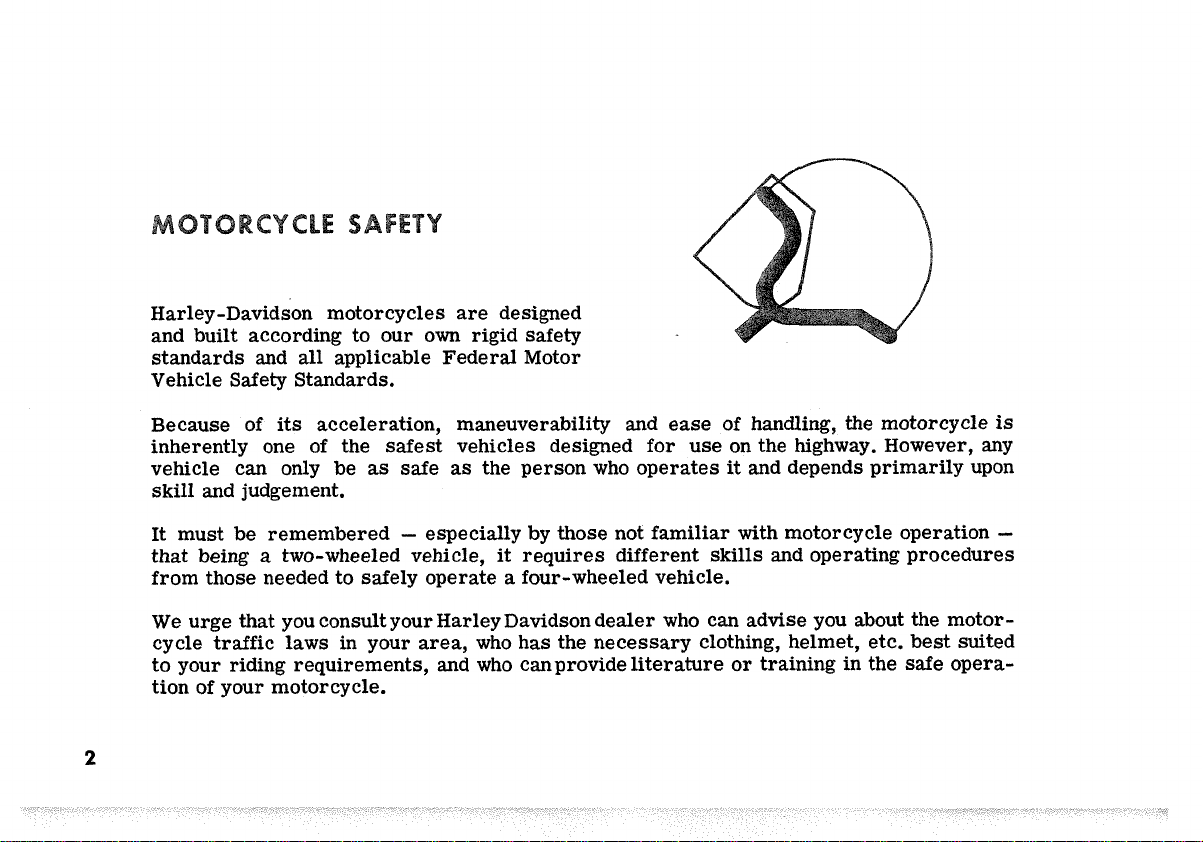
Harley-Davidson motorcycles are designed
and built according to our
all
standards and
Vehicle Safety Standards.
applicable Federal Motor
own
rigid safety
2
Because of
inherently one of the safest vehicles designed for use on the highway. However, any
vehicle can only be
skill
and judgement.
It must be remembered
that being a two-wheeled vehicle, it requires different
from those needed to safely operate a four-wheeled vehicle.
We urge that you consult your Harley Davidson dealer who can
cycle traffic
to your riding requirements, and who can provide literature or training in the safe operation of your motorcycle.
its
acceleration, maneuverability and ease of handling, the motorcycle
as
safe
as
the person who operates
-
especially by those not familiar
laws
in your area, who has the necessary clothing, helmet, etc. best suited
it
and depends primarily upon
with
motorcycle operation
skills
and operating procedures
advise
you about the motor-
is
-
Page 5

In
addition to this owner's manual, a Safeguard Main-
is
tenance booklet
owner. The booklet contains your new motorcycle
Warranty, a Warranty Registration card, and
ber of tear-out service coupons.
The approved service and maintenance procedures on each
coupon and the mileage intervals have been worked out by
Harley-Davidson service personnel,
are the owner's responsibility to have taken care
provided each new Harley-Davidson
a
num-
and
cover items which
of.
Bring the coupon booklet along when you vi
mileages to have your motorcycle ins
Dealer charges for "Safeguard Maintenance" are nominal
with long, trouble-free service and
Harley -Davidson product.
Tools for owner use,
service and minor repairs,
can be purchased from your Harley-Davidson dealer.
will
protect your investment
as
recommended in this handbook for
are
supplied in a tool kit which
it
your dealer at the specified
1
ected and serviced properly.
-
you
will
in
be repaid
a
quality
3
Page 6
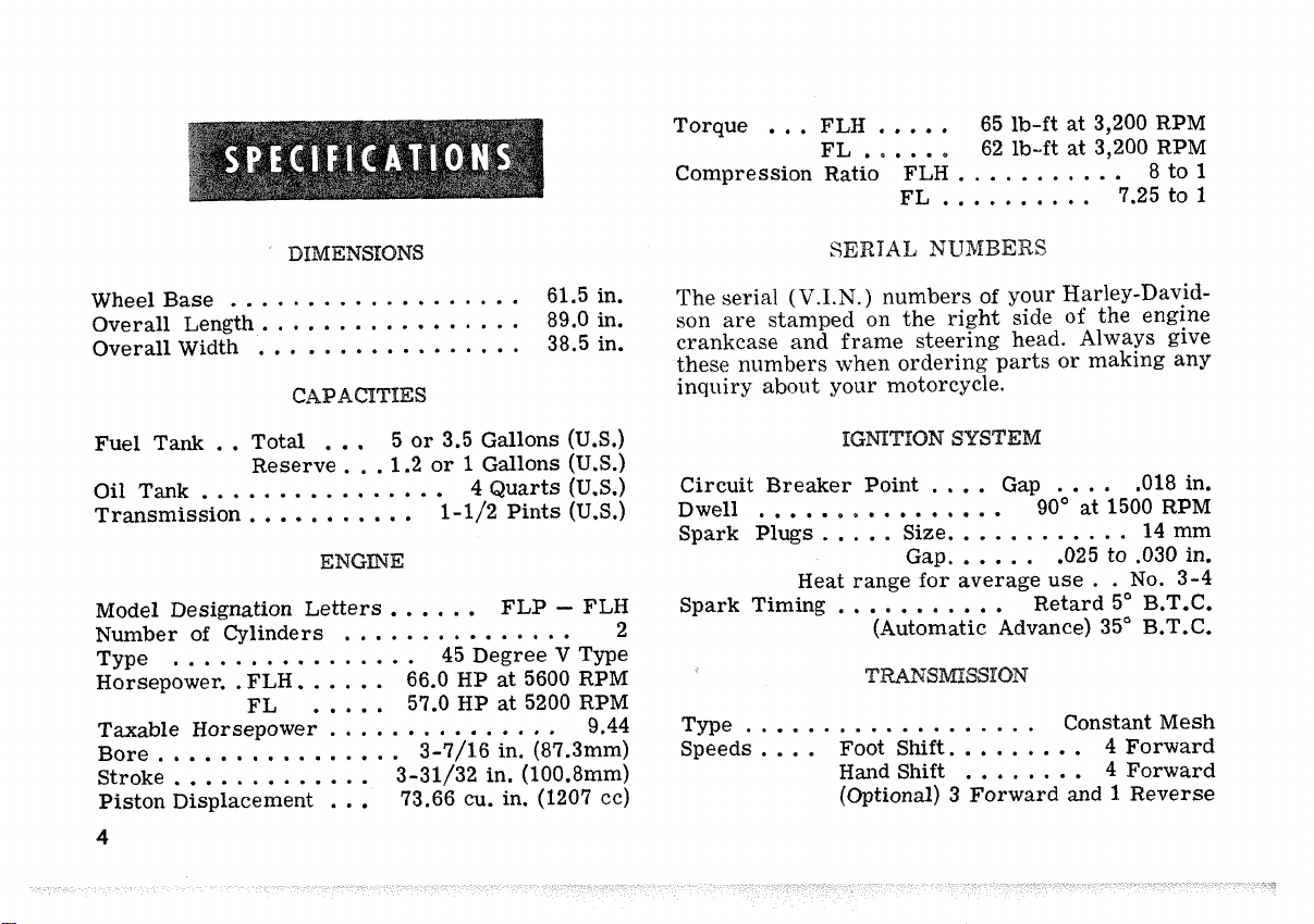
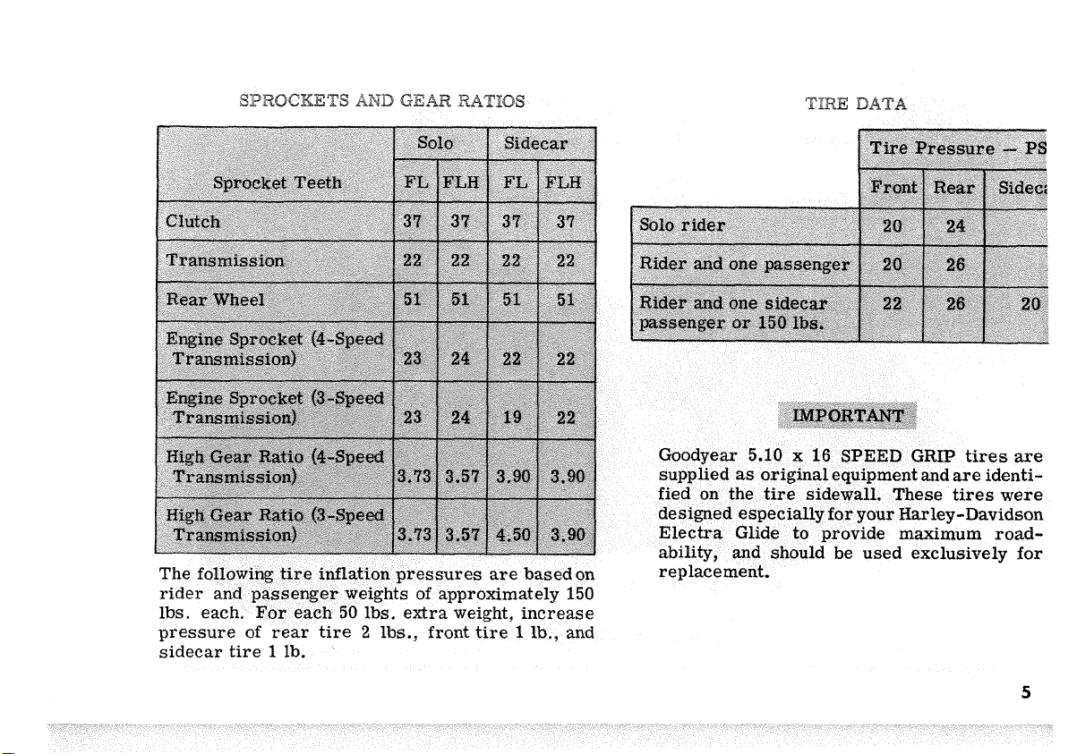
Torque
Compression Ratio FLH
...
FLH
FL
......
.....
FL
65
lb-ft
at 3,200 RPM
62 lb-ft at 3,200 RPM
...........
..........
7.25
8 to
to
1
1
Wheel Base
Overall Length.
Overall Width
Fuel Tank
Oil Tank
Transmission
Model Designation Letters.
Number of Cylinders
Type
Horsepower.
Taxable Horsepower
................
Bore
Stroke
Piston Displacement
4
...................
................
.................
..
Total
Reserve.
...
..
................
...........
...............
................
.
FLH.
FL
.....
.....
...............
.............
...
61.5 in.
89.0 in.
38.5 in.
5 or 3.5 Gallons
1.2
or 1 Gallons
4 Quarts
1-1/2 Pints
E
.....
66.0
57.0
3-7/16 in.
3-31/32 in.
73.66 cu. in. (1207 cc)
FLP
45 Degree V Type
HP
at
HP
at
(US)
(U.S.)
(U.S.)
(U.S.)
-
FLH
5600 RPM
5200 RPM
9.44
(87.3mm)
(100.8mm)
SERIAL
The serial
son are stamped
crankcase and frame steering head. Always give
these numbers when ordering parts or making any
inquiry about your motorcycle.
Circuit Breaker Point
Dwell
Spark Plugs..
Spark Timing
2
Type
Speeds
(V.I.N.)
................
...
Heat range for average use
...........
T
...................
....
Foot Shift.
Hand Shift
(Optional) 3 Forward
NU
numbers of your Harley-David-
on
the right side
ION
SYS
....
Size..
Gap.
.....
(Automatic Advance) 35" B.T.C.
S
of
Gap
....
90"
at
..........
,025 to .030 in.
Retard 5" B.T.C.
Constant Mesh
........
........
and
the engine
,018 in.
1500 RPM
14 mm
. .
No.
3-4
4 Forward
4
Forward
1
Reverse
Page 7
s
Page 8

Tail
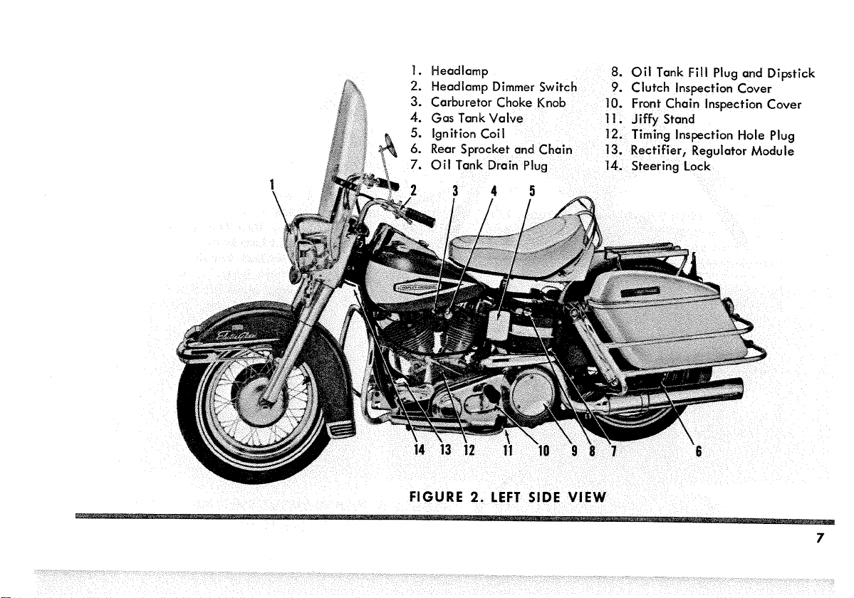
1.
2.
3.
4.
5.
6.
7.
Lamp
Oil
Filter
Carburetor Air Cleaner
Hydrau
I
ic
Fork
Safety Guard
Brake
Master Cylinder
8.
Ignition Circuit Breaker Cover
9.
Oil
Pump and Pressure Switch
10.
Starter Motor and Relay
11.
Transmission
12.
Battery
13.
Hydraulic Shock Absorber
Oil
Filler
Plug
FIGURE
1.
RIGHT
SIDE
VIEW
Page 9
3.
Carburetor
4.
Gas
C
TankVa
7
Page 10
1,
2
3
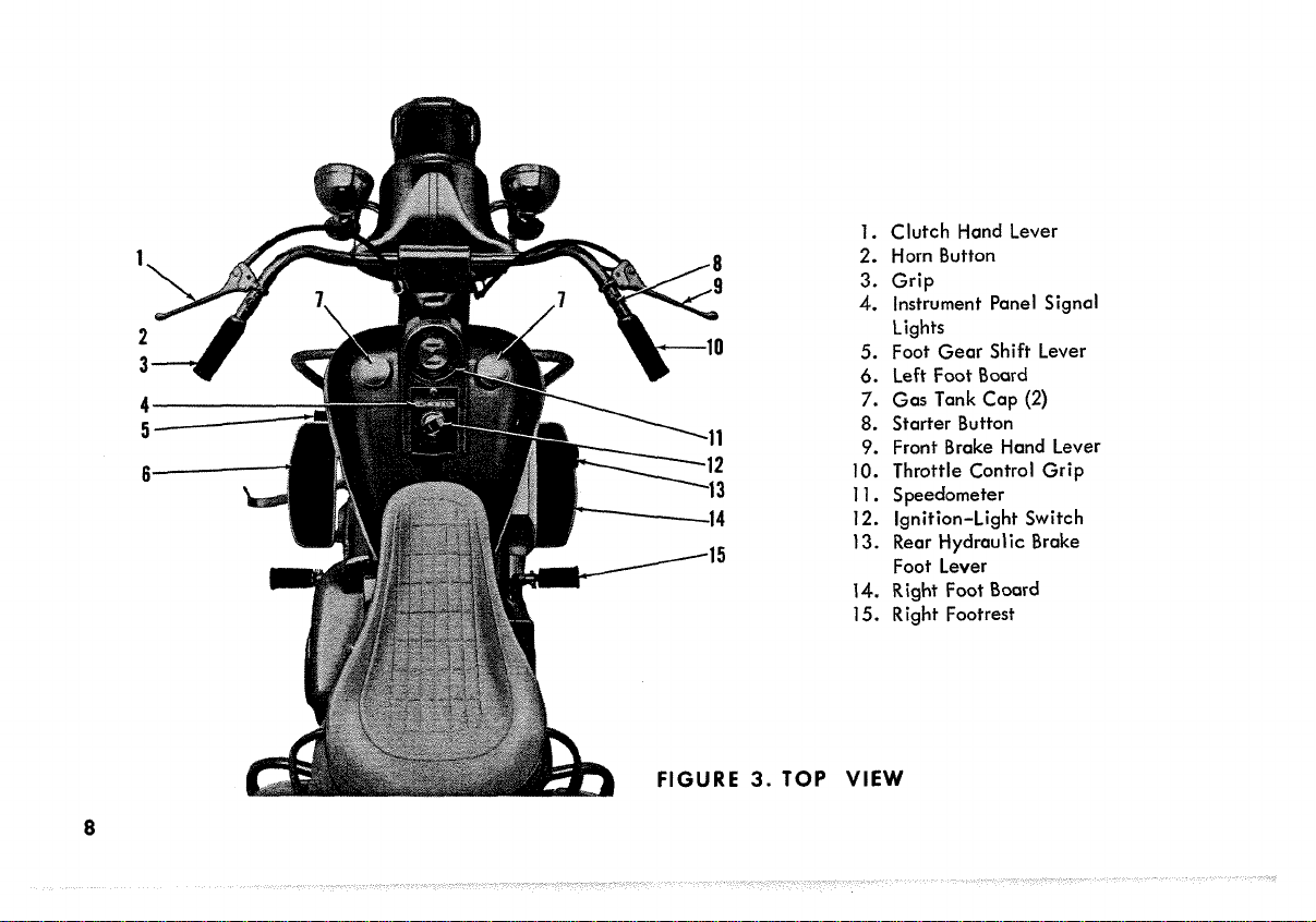
1.
Clutch Hand Lever
2.
Horn Button
3.
Grip
4.
Instrument Panel Signal
Lights
5.
Foot Gear Shift Lever
6.
Left Foot Board
7.
Gas Tank Cap
8.
Starter Button
9.
Front Brake Hand Lever
10.
Throttle Control Grip
11.
Speedometer
12.
Ignition-Light Switch
13.
Rear Hydraulic Brake
Foot Lever
14.
Right Foot Board
15.
Right Footrest
(2)
8
E
3.
TOP
VIEW
Page 11
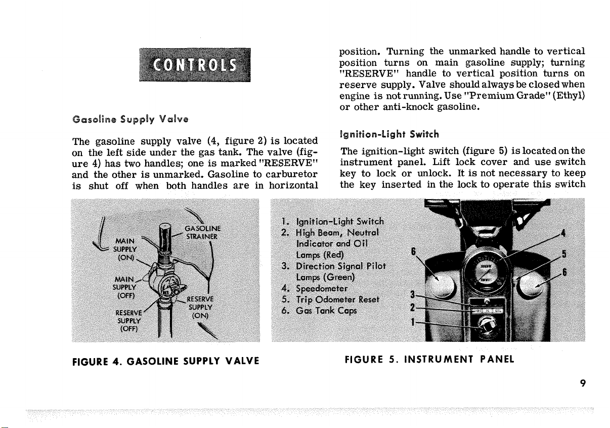
position. Turning the unmarked handle to vertical
position turns on main gasoline supply; turning
"RESERVE" handle to vertical position turns on
reserve supply. Valve should always be closed when
is
engine
or
other anti-knock gasoline.
not running.
Use
"Premium Grade" (Ethyl)
The gasoline supply valve
left
on the
ure
4)
and the other
is
shut off when both handles are in horizontal
FIGURE
side under the gas tank. The valve (fig-
has
two
handles; one
is
unmarked. Gasoline to carburetor
4.
GASOLINE SUPPLY VALVE
(4,
figure
is
marked "RESERVE"
2)
is
located
..
~~~~
itc
The ignition-light switch (figure
instrument panel.
key to lock
or
the key inserted
FIGURE
5.
Lift lock cover and use switch
unlock.
INSTRUMENT PANEL
It
is
not necessary to keep
in
the lock to operate this switch
5)
is
locatedon the
9
Page 12
after
it
has been unlocked. The center position of
the switch
is
the off position for both lights and
ignition. The right (counter-clockwise) of center
position
(clockwise) position
second
The switch can be locked only in the
is
for parking lights only; the
is
for ignition only and the
left
position, for ignition and running lights.
off
and the park
first
left
positions. Remember that lighting the headlamp
is
when the engine
on. The headlamp upper and lower beams
trolled by
a
handlebar. High beam indicator lamp (figure
cates upper beam. Make
that
it
can easily be replaced in case of loss.
Throttle Control Grip
Turn throttle control grip
close throttle; turn
not running also turns the ignition
toggle switch
(2,
figure
a
record of key number
(10,
figure
it
inward to open throttle.
2)
3)
are
con-
on the left
5)
indi-
so
outward to
Clutch
The clutch foot pedal
where
foot. The clutch
Foot
Pedal
is
located on the
it
may be conveniently operated by the
is
engaged when the toe
and released when the heel
Hand
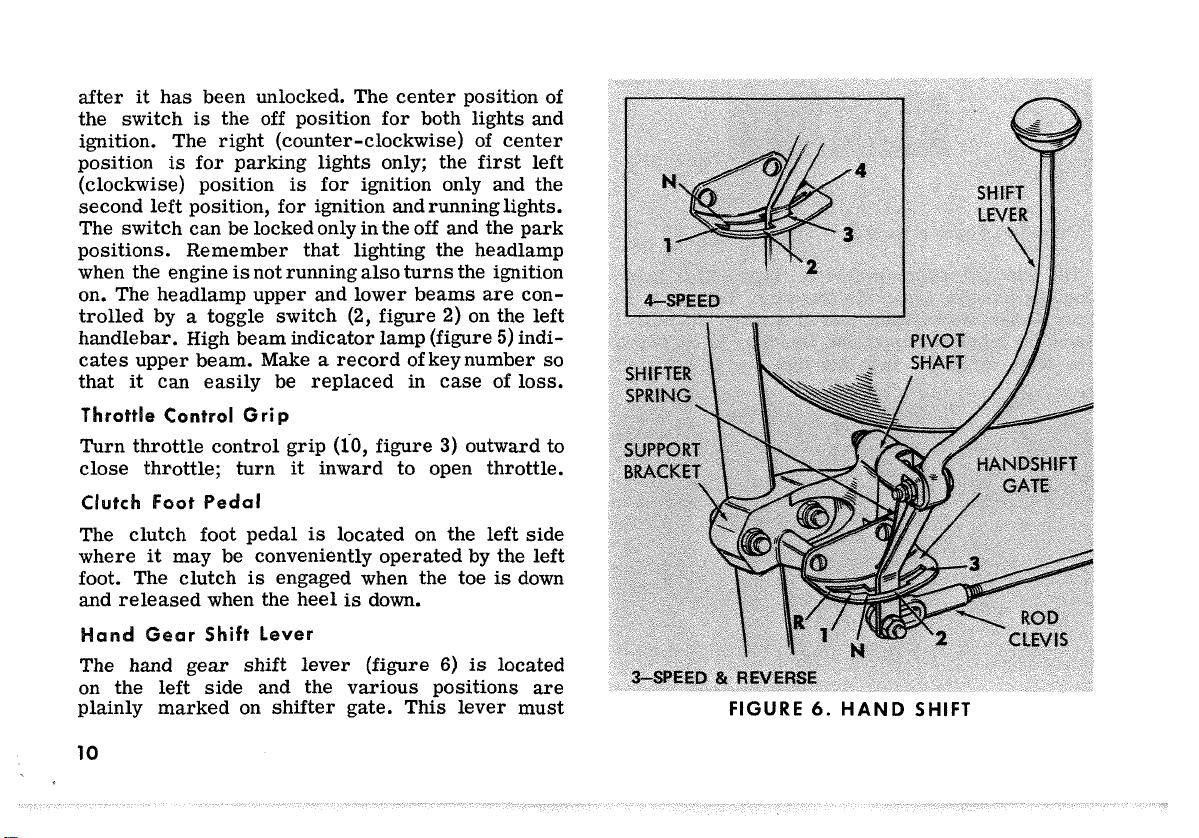
Gear Shift lever
The hand gear shift lever
on the
plainly marked
10
left
side and the various positions are
on
shifter gate. This lever must
is
down.
(figure
6)
left
is
is
side
left
down
located
FIGURE
6.
HAND
SHIFT
Page 13
be
at
neutral
(N)
and the clutch engaged when starting the engine. FULLY RELEASE THE CLUTCH
BEFORE SHIFTING. To shift gears, move upper
or
end of lever forward
rearward. This moves
lower portion of lever in opposite direction against
are
stops in gate where gear positions
VBfC
The clutch hand lever
the left handle bar where
(1,
figure
it
3)
can be conveniently
operated with the left hand. The clutch
marked.
is
located on
is
released
by squeezing the control lever toward the handle
bar. The clutch
control lever to
The foot gear
the
on
left
operated by
the
way down (full stroke)
into the next lower gear;
is
engaged by slowly releasing the
its
extended position.
shift
lever
side where
the
left foot. Pushing foot lever
(5,
figure
it
may be conveniently
shifts
transmission
lifting foot lever
3)
is
located
all
all
the
way up [full stroke) shifts transmission into the
next higher gear. The operator must release foot
it
lever after each gear change to allow
to
its
central position before another gear change
or
can be attempted
Neutral position
gears, and
is
indicated by center light (figure
made.
is
between
first
(low) and second
the instrument panel when ignition-light switch
turned on. First gear
is
the
last
to return
5)
on
is
gear position
obtained by pushing foot lever full strokes down-
ward.
foot lever one
To shift from
half
first
gear to neutral,
of its full stroke. The
lift
shift
to neutral can also be made from second gear
half
its
by pushing foot lever downward one
full
stroke.
With
the motorcycle standing
not running,
it usually
will
the motorcycle backward
clutch fully disengaged while maintaining
the
foot
pressure on
shift
still
and the engine
be necessary to move
or
forward with the
a
slight
lever before
a
shift
from one gear to +other can be made. Even
with
the engine running, clutch disengaged and
it
the motorcycle standing still,
shift
to
gears because transmission gears are
may be difficult
not turning and shifting parts are not lined up
to permit engagement. When this happens, do not
11
Page 14

under any circumstances force the shift by t'roughing" the foot lever; the results of such abuse
will
be
a
damaged or broken shift mechanism.
as
Either roll the motorcycle
if
or,
the engine
is
running, engage the clutch
indicated above
very slightly and at the same time apply light
pressure to the foot lever to make the shift.
Both these procedures
set
the transmission gears
in motion and permit the shift to be made easily.
r
The starter button
right handlebar. With ignition
(8,
figure
3)
is
located on the
ON
and transmission
in neutral, push button to operate starting motor.
ci
S
The brake foot pedal
hand side operates the
while a convenient hand lever
the front wheel mechanical
The steering lock
left
side of the lower front fork bracket. Turning
left
fork to the
steering head.
aligns hole in bracket with hole in
A
(13,
(14,
figure
rear
wheel hydraulic brake
brake.
figure
(9,
2)
3)
on the right
figure
is
located
3)
padlock can be used to lock the
fork in this position.
12
operates
on
the
Steering damper
head. Turn steering damper adjusting
is
located directly over steering
knob
clockwise to apply dampening action and counterclockwise to reduce dampening action.
For
solo riding,
apply steering damper only when operating under
conditions where some degree of dampening stabi-
lizes
tageous to keep the damper set
steering. Sidecar users will find
a
little
it
advan-
snug at
all times.
The horn
3)
on the
is
operated by the horn button
left
handlebar. Tone can be set
(2,
as
desired
figure
by turning the adjusting screw back of horn.
Page 15

655
The oil pressure signal light
strument panel (figure
Light
will
go on when the ignition-light switch
5)
is
located on the in-
and
is
marked
OIL.
is
turned on before starting the engine. After the engine has started, light should go off except
it
may
flicker on and off at very slow idling speeds.
turns to the
tank,
stop the engine at once and do
not drive farther until the trouble
and the necessary repairs
are
QP
made.
is
located
A
the oil.
y
signal switch,
ck the oil supply
if
oil supply
is
normal and the light
not go out, lo oil tank and see
the oil return from the outlet
the oil return e engine
If
it
is
returnin there
grounded
first,
still
is
running.
is
some circu-
or
Then,
does
if
of
lation, and you may drive slowly to the nearest
Harley-Davidson dealer to have the oiling system
as
checked and serviced,
needed.
If
no oil re-
This type fork
for sidecar service. The forks are pivoted
is
used on motorcycles intended
so
that
the wheel can be adjusted forward for less trail
or
(in sidecar service),
justed rearward for more
this
Normally,
as
shipped from the factory, and must be read-
fork
justed for sidecar service
1.
Raise
is
is
with
front end of motorcycle
free. Underneath fork head lower bracket
a
large bolt with castellated nut locked
a
cotter pin. This bolt fastens lower
the wheel can be ad-
trail
(in solo service).
is
adjusted for solo service
as
follows:
so
front wheel
fork bracket to fork stem bracket which has
a slotted hole for the bolt. Remove cotter
far
pin from nut and back off nut
so
that
lock plates underneath bolt head and
enough
bolt nut can be disengaged from slots in
each side of fork bracket. Now grasp front
13
Page 16
wheel and pull fork sides forward
as
far
as
elongated holes in bracket will permit. Reengage lock plates in elongated holes with
plate engaging to the front. Securely tighten
nut and insert cotter pin.
2.
Re-aim headlamp after fork
(See page
3.
For solo service, when sidecar
52.)
is
readjusted.
is
removed,
move fork back by reversing above procedure.
t
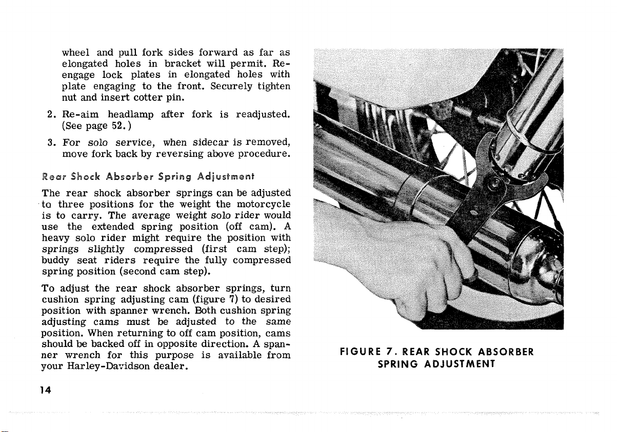
The rear shock absorber springs can be adjusted
ta
three positions for the weight the motorcycle
is
to carry. The average weight solo
use the extended spring position
(off
rider
cam).
would
A
heavy solo rider might require the position with
springs slightly compressed (first cam step);
seat
buddy
riders require the fully compressed
spring position (second cam step).
To
adjust the rear shock absorber springs, turn
cam
cushion spring adjusting
(figure
7)
to desired
position with spanner wrench. Both cushion spring
adjusting cams must be adjusted to the same
position. When returning to off cam position, cams
A
should be backed off in opposite direction.
is
ner wrench for this purpose
available from
span-
your Harley-DaTidson dealer.
EAR
SHOCK
SPRING ADJUSTMENT
ABSORBER
14
Page 17
IMPORTANT
If
you are not familiar with operating the
motorcycle, read paragraphs on "SAFETY"
(page
2)
and
"CONTROLS"
(page
9)
before
riding this motorcycle.
irst
5
es
The sound design, quality materials, and workman-
that
is
ship
will
give you high performance rightfromthe
However, for the
built into your new Harley-Davidson
start.
first
few hundered miles, to wear-
in critical parts, observe the few simple driving
will
rules below. This
guarantee future performance
and durability.
1.
During the
45
miles per hour.
2.
Up to
first
50
miles, keep the speedbelow
500
miles, vary the speed, avoiding any
steady speed for long distances. Any speed up
to the maximum legal limit
is
permissible
for short distances.
3.
Avoid
fast
starts
at
wide open throttle and
over-speeding engine in lower gears. Drive
slowly until engine warms up.
ing
lns~ruct~~ns
IMPORTANT
Use recommen ation to predominating temperatures. See engine lubrication, page
24.
When starting the engine determine thatthe motor-
cycle
is
in neutral and
that
the clutch
is
fully
engaged.
is
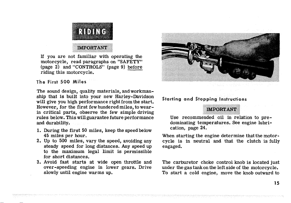
The carburetor choke control knob
the
left
side
under the gas tankon
To
start a cold engine, move the knob outward to
of the motorcycle.
located just
15
Page 18

the fully closed (choke) position; with throttle
to
1/4
open, turn ignition switch on and operate
the
starter.
To
start
a
warm
or
hot engine move choke knob out-
1/2
ward to
turn on ignition switch and operate the
soon
as
enough to keep
ready to
warms up and misfires, because of the over-rich
mixture, gradually open choke by moving choke knob
inward.
choke knob should be all the way in.
When the engine does not
revolutions
but engine does not
cause ,of an over-rich (flooded) condition.
This
the engine
turn ignition on and operate
choke and throttle wide open.
closed position,
the engine
set
the motorcycle in motion.
After
the engine has thoroughly warmedup,
is
especially true of a hot engine.
is
starts,
it
running while warming up
or
if
one cylinder
flooded, open choke
set
throttle
open throttle just
As
start
after afew
fires
start,
it
is
usually be-
all
starter
starter.
the engine
weakly
the way,
1/4
or
1/8
open,
As
far
until
If
with
Start the engine, fully release the clutch, shift
into
first
desired speed
the clutch,
shift into second and again engage clutch. Shift
in like manner for third and fourth gears.
DO
NOT SHIFT GEARS WITHOUT FULLY DIS-
ENGAGING THE CLUTCH.
When the motorcycle
is
shift from "third" to "second" until speed
is
from "second" to
duced to below
gears when speeds
in
Stopping the Engine
and slowly engage the clutch.
is
attained in
lift
the foot lever
desired to shift to lower gears, do not
reduced to
20
mph
"first"
10
damage to the transmission.
first,
fully disengage
all
the way up to
is
in motion and it
or
less;
do
not shift
until speed
mph. Shifting to lower
are
too high may result
is
re-
After
Operation
With motorcycle standing (engine stopped) proceed
as
follows to get under way. Determine that trans-
is
mission
16
in neutral and clutch
is
fully engaged.
Stop the engine by turning off the ignition switch.
If
the engine should be stalled
other way than with the switch, turn off the switch
at
once to prevent battery discharge through the
circuit breaker points.
or
stopped in any
Page 19
5
To prevent possible vapor lock with a hot engine
start
in very warm weather,
and leave
richer mixture and cool carburetor. Develop the
habit
instant when running
additional lubrication to pistons and cylinders and
helps cooling.
Do not idle engine unnecessarily with motorcycle
standing.
is
thoroughly warmed up to avoid possible damage
to pistons, rings, and other parts before oil
enough to circulate freely.
An
speed, particularly in sidecar service, must be
given closer than ordinary attention to avoid over-
heating and possible consequent damage. Have the
engine checked regularly and keep
Valve seating and good compression
larly important. The carburetor intermediate speed
needle should be adjusted moderately rich rather
than lean.
suit type of service. This applies particularly to
motorcycle equipped with windshield and splash
shields-or lap apron.
at
half choke for a few blocks to provide
of
frequently snapping the throttle shut for
at
In
cold weather
engine which has run long distances
Use
correct heat range spark plugs to
engine
high speed. This draws
run
engine slowly until
at
half choke
is
at
it
well tuned.
are
particu-
an
it
warm
high
The spark plugs originally installed in the engine
are of the proper heat range for most normal operating conditions. However, more severe than average
or
service
plug
of
in the case of very severe
case
When plugs need to be replaced, get them from
your Harley-Davidson dealer. He can supply you
with the type of plug
ments. Experimenting with plugs of unproven quality
and suitability
loc~ting Operating Troubles
The following check
their probable causes will be helpful in keeping
your motorcycle in good operating condition. Remember that more than one of these conditions
may be causing the trouble and
carefully checked.
df
engine
1.
Spark plugs in bad condition
a
gap
2.
Circuit breaker points out of adiustment
need
very light service may call for a spark
adifferent heat range to prevent overheating,
of very light service.
best
is
inviting trouble.
list
starts
hard
or
runs unevenly
service
suited to your require-
of
operating troubles and
orfouling in the
all
or
have improper
-
of
cleaning.
should
or
misses:
or
be
in
17
Page 20

Condenser connection loose.
3.
Battery nearly discharged.
4.
Loose wire connection
5.
at
minals or
Water or dirt
6.
Gasline tank cap vent plugged
7,
vent line closed
Carburetor not adjusted correctly.
a.
Engine and transmission oil too heavy (winter
9.
operation).
df
cranking motor does not operate:
1.
Ignition switch
2.
Starter button or relay defective.
3.
Discharged battery, or loose or corroded cable
connections (solenoid chatters).
4.
Starter control circuit wiring defective.
/
dIf
engine turns over but does not
Gasoline tank empty, valve shut off or gaso-
1.
line line clogged.
Fouled spark plugs or shorted spark plug
2.
wires.
Circuit breaker points
3.
Loose wire connection at coil or circuit
4.
breaker
coil or circuit breaker.
in
fuel system and carburetor.
off
is
not on.
.
at
one of battery ter-
or
carburetor
restricting fuel flow.
start:
badly
out
of
adjustment.
5.
Sticking valves or tappets set too tight.
.
Engine flooded
a
spark plug fouls repeatedly:
1.
Too
cold a plug for the kind of service.
2.
Piston rings badly worn or
engine pre-ignites:
1.
Excessive carbon on piston head or in com-
bustion chamber.
2.
Too
hot a spark plug for the kind of service.
3.
Defective spark piugs.
/
If engine overheats:
1.
Insufficient oil supply or oil not circulating.
2.
Carburetor high speed adjustment too lean.
3.
Ignition timing too late,
df
engine detonates:
1.
Unsuitable fuel (octane rating too low).
2.
Heavy deposit of carbon on piston and in com-
bustion chamber.
3.
Defective spark plug or of wrong heat range.
4.
Ignition timing too early.
f
oil does not return to oil tank:
1.
Oil tank empty.
2.
Oil pump not functioning.
as
a
result of overchoking.
in
bad condition.
18
Page 21

engine uses too much oil:
1.
Piston rings badly worn
2.
One
or
more push rod cover cork washers in
bad condition
properly against
3.
Rear chain oiler setfor excessive amount of oil.
vibration
.
Cylinder bracket loose
2.
Engine mounting bolts loose.
3.
Transmission and/or transmission submount-
ing plate loose.
4.
Tires
is
or
or
a
its
excessive:
wheels defective.
or
in bad condition.
push rod cover not seating
washer.
or
broken.
transmission shifts hard
1.
Bent shifter rod.
2.
Clutch dragging slightly.
.
Transmission oil too heavy (winter operation).
transmission jumps out of gear:
1.
Shifter rod improperly adjusted.
2.
Shifter clutch dogs and/or dogs on
gear badly worn.
clutch slips:
.
Clutch controls improperly adjusted.
2.
Insufficient clutch spring tension.
3.
Friction discs oily.
its
mating
If
alternator does not charge
below normal:
1.
Defective regulator-rectifier module.
2.
Loose, broken,
to module circuit;
3.
Defective alternator stator
carburetor floods:
1.
Inlet valve and/or valve
2.
Dirt between float valve and
3.
Excessive "pumping"
or
shorted
or
or
module to battery circuit.
seat
of
hand throttle grip.
charging rate
wires
in alternator
or
rotor.
worn
or
its
seat.
is
damaged.
clutch drags
.
Clutch controls improperly adjusted.
2.
Clutch spring tension too tight.
3.
Friction discs gummy
brakes do not hold normally:
1.
Brake improperly adjusted.
2.
Brake controls binding
lubrication
3.
Brake linings badly worn
4.
Hydraulic system contains
inder reservoir low on hydraulic brake fluid.
5.
Leak in hydraulic system.
or
does not
or
damage.
release:
or
oily.
as
result of improper
or
glazed.
air
or
master cyl-
1
Page 22

Keep on the right side of the road when meet-
1.
ing other vehicles coming in the opposite
direction.
Always sound your horn and pass on the left
2.
side when passing other vehicles going in
the same direction. Never try to pass an-
other vehicle going in the same direction
at
street
going up
3.
At
street intersections give the right-of-way
to the vehicle on your right.
intersections, on curves,
or
down
a
hill.
Do
or
not presume
too much when you have the right-of-way; the
other driver may not know you have it.
Always signal when preparing to stop, start,
4.
or
turn.
All
5.
traffic signs, including those used for the
control of traffic
at
intersections, should be
obeyed promptly and to the letter. "Slow Down''
signs near schools and caution signs
at
road crossings should always be observed and
your actions governed accordingly.
when
rail-
6.
Never "crash" a light. When a c
cated from
the traffic control systems
await
the change.
7.
When intending to turn to the left, give signal
at
least
q'Go" to "Stop"
100
feet before reaching the turning
(or
vice versa) in
at
intersections,
point. Move over to the center line of the
street (unless local rules require otherwise),
slow down passing the intersection
street and then turn carefully to the
8.
In turning either right
destrians
9.
Do not leave the curb
as
well
as
signaling and seeing that your way
drive into moving
or
left, watch for pe-
vehicles.
or
parking area without
traffic.
A
moving line of
is
traffic has the right-of-way.
10.
See that your license tags are installed in
the position specified by law and that they
are
clearly visible under
all
conditions. Keep
them clean.
11.
Ride
at a
safe speed
the type of highway you
whether the road
condition on
the
-
a
speed consistent with
are
on, and always note
is
dry
or
wet. Each varying
highway means adjusting your
speed accordingly.
of
the
left.
clear to
20
Page 23

re:
After
a
new motorcycle has been driven
500 miles and again
its
at
approximately 1000 miles,
first
the motorcycle should be taken to the dealer from
whom
operations with which the dealer
If
dealer
owner should
attention,
it
was purchased for certain initial service
is
familiar.
it
is
impossible to take the motorcycle to
at
the mileage intervals mentioned, the
at
least give the following outlined
or
arrange to have
it
given, and take
a
the motorcycle to the dealer for more complete
servicing
1.
Drain oil tank through drain plug
later
on
when convenient to do
(7,
figure
so.
2)
flush tank and refill with fresh oil.
2.
Clean oil filter, crankcase screen for overhead
and tappet oil supply and magnetic plug in
chain housing.
3.
Drain transmission through drain plug and
refill
to level
of
filler
opening with fresh oil.
Use same grade oil used in engine.
4. Lubricate
attention in the SERVICE
all
points indicated for
AND
2000
mile
MAINTENANCE
CHART.
5. Aim headlight.
6.
Check front fork bearing adjustment.
7.
Clean carburetor gas strainer.
8.
Clean chain housing magnetic drain plug.
9.
Inspect and clean spark plugs.
10, Check ignition timing and circuit breaker
point gap.
11.
Oil
all
control joints and parts indicated for
2000
mile attention.
12.
Inspect and service
13.
Check adjustment of chains and readjust
air
cleaner
if
needed.
if
necessary.
14. Check lubrication of chains.
15. Check
all
nuts, bolts and screws, and tighten
any found loose.
16. Check wheel mounting socket bolts and tighten
if
needed. These bolts must be kept very tight.
17. Check and tighten wheel spokes.
21
Page 24

18. Check level of solution in battery and add
if
distilled water
needed. See that terminals
are clean and connections tight.
19. Check tightness of
and
all
cylinder base nuts, and tighten where
all
cylinder head bolts
necessary.
20. Check brake adjustment and hydraulic fluid
level.
21.
Check clutch adjustment.
22. Check tire pressure and inspect tread.
23. Road test.
FI
1.
Drain oil tank and refill with fresh oil.
2. Clean oil filter.
3. Check level of oil in transmission and add
if
oil
engine.
4.
5.
6.
7.
needed. Use same grade of oil used in
Service
air
cleaner.
Check circuit breaker point gap.
Check adjustment of chains and adjust ifneces-
sary.
Check lubrication of chains.
8. Check level of solution in battery, and add
distilled water
are
clean and connections tight.
if
needed. See that terminals
..
9. Check brake adjustment and hydraulic fluid
level.
10. Check clutch adjustment.
11.
Check tire pressure and inspect tread.
12. Road
test.
s
Regular motorcycle lubrication and maintenance
will help you keep your new Harley-Davidson
operating
lower operating costs, longer motorcycle
at
peak performance, and will give you
life,
and greater riding pleasure. Your Harley-Davidson
dealer knows best how to service your motorcycle
with factory approved methods and equipment
as-
suring you of thorough and competent workman-
ship for every job.
The chart on the next page shows the regular
at
intervals
should be performed.
which specified service operations
For
more detailed description
of the service and maintenance procedures specified,
refer
to information following after chart.
22
Page 25

S
CE
23
Page 26

Run engine until
1.
ture.
Remove fuel supply hose at tank and drain gas
2.
tank, including reserve supply
Mix about
3.
of gasoline and put in gas
Run engine with gas-oil mix for several minutes
4.
until exhaust smokes.
Remove spark plugs, inject
5.
cycle oil into each cylinder and crank engine
or
6
5
Drain oil tank.
6.
See that rear chain
7.
Wax chrome plated surfaces and apply some oil
8.
to exposed unpainted surfaces.
Store battery above freezing temperature,
9.
trickle charge at least once
water level above plates.
from motorcycle
on ground or concrete.
When riding time comes again, your motorcycle
be
will
24
revolutions.
ready. Just
it
reaches operating tempera-
-
replace hose.
4
ounces of 2-cycle oil in one quart
tank.
a
few squirts of
Clean and replace plugs.
is
clean and well lubricated.
a
month, and keep
If
battery
it
must not be placed directly
fill
the oil tank,
start
is
removed
up and go
2-
Your Harley-Davidson dealer has the proper grade
oil to suit your requirements.
indiscriminately
chemically when mixed.
The oil tank capacity
full when the oil level
stick. Tighten the cap securely to prevent leakage.
The oil signal light
cates oil circulation. Oil mileage normally varies
from 250 to
nature
driving, and
mileage
!
of
service, solo
is
not within this range, see your dealer.
-
some oils tend
is
4
is
on
500
miles per quart depending on the
or
how^
well the engine
Do
not switchbrands
to
quarts and
at
upper mark on the dip-
the instrument panel indi-
sidecar,
is
considered
fast
or
is
kept tuned.
interact
moderate
If
Page 27

Remove tank cap
MORE THAN
REFILL.
If
and
CHECK OIL SUPPLY NOT Oil will run cooler and mileage
300
MILES AFTER EA COMPLETE
oil level
is
at
lower m on dipstick,
higher with oil level well up
unless oil tank
two quarts can be added. ing of oil level
chance of running dry.
will
be somewhat
in
tank. Furthermore,
is
kept well filled, frequent check-
will
be necessary to avoid any
Do not allow oil level to go below the lower
Oil should be changed after the
1000
and
at
at
about
warm
miles for a new engine, and thereafter
2000
mile intervals in normal service
or
moderate temperatures. Oil change
first
500
miles
mark on gauge rod. intervals should be shorter in cold weather
See 'Winter Lubrication." Completely drain oil
tank of used oil and refill with fresh oil.
vice
is
extremely hard
competition, drain and
Draining should be done after
It
is
not necessary to drain the crankcase
or
on dusty roads
refill
at
shorter intervals.
a
run while oil
not accumulate used oil. At the time of the
mile oil change, and along with
at
least every second
as
first
If
is
it
ser-
or
does
oil change thereafter, thoroughly flush and clean
tank with kerosene to remove any sediment and
sludge that may have accumulated. Your dealer has
facilities for quick flushing and cleaningof oil tank.
UPPER
MARK
(FULL)
LOWER
MARK (ADD OIL)
-
in
hot.
500
out
25
Page 28

Oil filter
service the filter, unscrew wing nut and remove
filter cup from oil
from top of filter anddisassemble. Thoroughly wash
the filter element in clean gasoline
least once every
changed. Renew filter element every
Overhead and tappet oil filter screen
is
located in crankcase above oil pump. Unscrew
slotted plug, remove and clean
The chain housing magnetic drain plug
13)
is
screw plug and remove foreign material from end
of plug. This should be done when engine oil
changed initially
thereafter.
Combustion in any engine generates water vapor.
When starting and warmingup in cold weather, much
of the vapor condenses to water on relatively cool
metal surfaces.
crankcase thoroughly warmed up, frequently, most
is
located
located
2,000
at
bottom
at
If
engine
at
the top of the oil
tank,
remove retaining spring
or
miles when the engineoil
5,000
ic
(3,
or
replace screen.
(11,
rear
of chain housing. Un-
500
miles and every
is
driven enough to get the
2,000
tank.
solvent
miles.
figure
figure
miles
To
at
is
9)
is
of
this water
through the breather. owever,
engine, making only short runs now and then and seldom being thoroughly warmed up,
mulate an increasing amount of water in the oil tank.
This water will, in freezing weather, become slush
or
ice and
block oil lines
mixed with oil for some time forms sludge that
harrnful to the engine and causes undue
ious working parts. Therefore, in winter the oil
change interval should be shorter than normal for
all
engines, and any engine used only for short runs,
particularly in commercial service, must have oil
changed frequently along with
out to remove any water and sludge, beforenew oil
is
put in tank. The farther below freezing the tem-
perature drops, the shorter the oil change interval
should be.
In
normal service on hard surfaced roads, remove
air
cleaner mesh, wash in gasoline, and saturate
with engine oil
under dusty service conditions.
service, clean and oil filter mesh every
or
at
least
is
again vaporized and blown out
a
moderately driven
is
likely to accu-
if
allowed to accumulate too long,
and
damage the engine. Also, water
a
thorough tankflush-
at
least
every
1000
miles,
In
extremely dusty
once a day.
wear
or
100
will
is
of
var-
oftener
miles
26
Page 29

The gasoline strainer
is
located on top of the
gasoline supply valve inside the gasoline tank
(see
figure
as
indicated by irregular carburetion, remove the
4).
If
the supply of gasoline
is
impeded,
gasoline supply valve from the tank and thoroughly
clean the gasoline strainer. Be sure to drain the
tank before removing the gasoline supply valve.
1'
2
1.
Chain Inspection Cover
3.
Chain Housing Cover Screws
FIGURE
5.
Clutch Cover Screws
8.
CHAIN INSPECTION COVER
3'
2.
4'
Inspection Cover Screws
(8)
4.
Clutch Cover
(3)
(4)
Use
same grade of oil used in engine.
Remove transmission oil filler plug
(11,
figure
1)
and check oil level every month or every 10
miles, whichever comes
fill
and
to the level of the filler opening. The
motorcycle should be standing
Add oil
STRAIGHT
if
necessary
UP,
not
first.
leaning on jiffy stand, when adding oil to the
transmission. Drain transmission and
refill
to
correct level with fresh, clean oil after the first
500 miles, and thereafter seasonally or every
5,000 miles, whichever comes
should become submerged in water, drain
first.
If
transmission
it
im-
mediately and refill to proper level.
is
A fixed amount of oil
line from
a
metering orifice in the oil pump. Oil
supplied through an oil
drops on front chain from oiler outlet tube (10,
figure 13). Excess oil collects
is
compartment and
drawn back into engine gear
at
rear of chain
case breather.
27
Page 30

When the front chain adjustment
2000 mile intervals (see page
to
see
that oil comes out of oiler tube when
is
engine
inspection hole
from oiler, supply orifice
running, when viewing through cover
(1,
figure
8).
at
is
checked
43)
,
also check
If
oil does not come
pump
is
probably
at
blocked due to accumulation of dirt, and requires
cleaning.
To
do this, remove orifice screw and
washer from oil pump and blow out passage to
chain compartment with compressed
air.
Motorcycle
At
regular 2,000 mile intervals, make a close
inspection of
appear to be getting sufficient lubrication, or
there
is
is
evidence of
equipped with
rear
chain.
an
a
rear
chain oiler.
If
rear
chain does not
if
over-supply of oil, re-
adjustment should be made with rear chain oiler
adjusting screw. The
the oil pump
is
1/4
turn open which provides 2
minute.
as
shown in
If
oiler should become blocked, remove
chain oiler
figure
is
locatedon
9.
Normal setting
or
3
drops per
rear
screw and clean orifice.
If
chain oiler
chain and lubricate
is
not being used, brush dirt off
at
1000
mile intervals with
Harley-Davidson "Chain Saver," "Chain Spray" or
28
3.
1.
Rear Chain Oiler Adjusting
Screw Tappet and Overhead
2.
Rear Chain
Screw Locknut
Oiler
FIGURE
Adjusting
9.
REAR
Cover Plug
Oil
CHAIN
OILER
for
Supply Screen
Page 31

"Chain Grease"
engine oil.
If
the motorcycle
dusty
lubrication of the
time to time. Under these conditions, proceed
follows:
Remove chain from motorcycle.
thoroughly in a pan of kerosene. Remove chain
from kerosene and hang
kerosene to drain off. Immerse for
in
engine oil.
not
move chain around to
oil works through
from hot grease
wipe
of
connecting link and spring clip closely
condition. Replace
spring clip
pin ends.
or
dirty conditions, thorough cleaning and
a
pan of grease heated to consistency of light
at
hand, substitute engine oil. While immersed,
all
surplus grease
the chain. Install chain on motorcycle. Inspect
if
available;
is
operated under extremely
rear
chain may be advisable from
If
grease and facilities for heating are
be
all
inside parts. After removing
or
oil, allow chain to drain and
if
not available, use
Soak
and wash
it
up for a time to allow
a
short time
sure that hot grease
or
oil from the surface
for
if
at
all
questionable. Be sure
is
properly and securely locked on
as
it
or
bad
ey-Davidson "Grease All" for greasing
requirements.
All chassis bearings requiring frequent applications of grease are provided with grease gun
fittings. Locations and recommended greasing
intervals
TENANCE CHART (Page
Use
Excess grease produces
Remove and grease handlebar throttle grip spiral
with fresh grease every
operation
Remove and grease speedometer and tachometer
drive cables every
On grease fitting of
apply
of
grease gun) to fitting
with hand grease gun.
are
listed in the SERVICE AND MAIN-
23).
a
hand grease gun to avoid over-greasing.
a
messy condition.
5,000
of
grip indicates lubrication
5,000
miles.
rear
fork
a
very small quantity of grease (one stroke
at
miles, or when
is
necessary.
pivot bearing housing,
2,000
mile intervals
29
Page 32

CAUTION
an appreciable amount of oil leakage should de-
attention should
e given by an authorized
y-Davidson dealer.
Over-greasing will damage seals.
Pack the steering head bearings with fresh grease
at
50,000
miles.
Incorrect recoil action will result
sufficient oil in either side of the fork.
the amount, completely drain the oil and then
pour back into each side
6-1/2 to
if
there
To
7
ounces of
is
in-
check
Harley-Davidson Hydraulic Fork Oil. Oil drained
from the fork may be used again provided
does not appear to be contaminated by water or
other foreign matter. Add only enough fresh oil
All control connections and parts
as
indicated in
to provide the required amount.
the SERVICE AND MAINTENANCE CHART (Page
23)
should
be oiled regularly, particularly after
washing motorcycle
Pa-
or
driving in wet weather.
fork should
water, drain and
In
an
emergency, when Harley-Davidson Hydraulic
Fork Oil
at
any time become submerged in
refill
immediately.
is
not available, use the lightest auto-
If
The Hydra-Glide fork requires very little main- mobile engine oil obtainable. Do not use shocktenance or attention. It requires no greasing.
fork does not appear to be working properly, or drain and replace with Hydraulic Fork
If
absorber fluid.
If
engine oil
is
used, however,
Oil
as
soon
30
it
Page 33

consistency of engine oil varies
changes, and
a
rough ride will
and
emper atur e changes
ommended oil.
To
drain and refill fork, remove headlamp and
headlamp housing, then remove the hex headcap
at
screw
drain plug
3/16 inch Allen wrench, and drain the oil into
clean container. Add oil to container,
to make up the required amount. Replace the
drajn plugs and add 6-1/2 to
through the hole in the upper end of eachfork
tube. Then install the cap screw and tighten
securely.
Filling the fork using only
slow job because the
are
air
locked. It
Harley-Davidson dealer when this service
quired,
the job cleanly and quickly.
The adjustable
equipment for sidecar service) does not have
hex head cap screw
but has oil
the top
at
small and the
as
he
of
each fork side. Remove the
the lower end of each slider with
filler
filler
is
recommended that you see your
has
the necessary equipment to do
trail
filler
plugs
channel tends to become
Hydra-Glide Fork (special
at
the top of each fork side,
at
stiff
recoil action
at
lower temperatures.
little
effect on the rec-
if
necessary,
7
ounces of oil
a
funnel
openings in the fork
the rear of each fork
is
a
rather
is
a
a
re-
a
e
removed with a large screw-
Every
cylinder
brake foot pedal. When removing
sure that
plug to prevent entrance into reservoir. Level
should be 1/4 inch from top of cover.
HYDRAULIC
for use in hydraulic brake systems.
It
and miles of service, which
in determining
so
Inspect level of battery solution
week during motorcycle operation, adding distilled
or
keep the solution above the plates.
cycle
check solution level before placing in service.
Remove battery cover and take out 6 screw end
filler
1000
miles, check fluid level in master
(6,
figure
all
dirt
BRAKE
is
the
care
lilt
ion
other approved water
is
not used for an extended period of time,
plugs. With a hydrometer
1)
located just ahead of re
is
removed from around
FLUID, which
given a battery, rather than time
its
life.
as
filler
is
is
most important
at
least
often
as
necessary to
If
or
syringe, add
plug,
filler
Use
only
approved
once
the motor-
a
31
Page 34

water to each cell to
triangle or circle
at
base of filler hole.
raise
level of solution up to
is
especially important that the battery be kept
well charged in below freezing weather. A low or
discharged battery
very likely to
be
frozen
is
and ruined.
If
battery
of the solution
the vent holes when battery
This
is
filled
will
not only weaken the solution,
to a higher lever, some
will
be
forced out through
is
charging.
but also may damage parts near the battery.
Avoid getting battery acid on clothing
other
fabrics.
Keep battery clean and ter-
or
minal connections tight.
hwgin
Check solution in each cell
drometer.
If
hydrometer reading
remove battery and charge
source. The charging current should be
with
a
battery hy-
is
below
it
from an outside
1.200,
12
volt
direct current and charging rate should not be
allowed to go over
4
amperes.
A higher battery charge rate may heat and damage
the battery.
E'or
this
reason, do not allow the
motorcycle battery to be charged in the same
line with auto batteries. Hydrometer reading of
fully charged battery in good condition will be
from
1.265
to
1.300.
Allowing battery to remain in a discharged con-
its
dition for any length of time shortens
life. It
32
CIS
Keeping the motorcycle clean on the outside
well
as
on the inside not only
maintenance, it
$
good maintenance. To
keeping your motorcycle clean
Davidson
dealer
for the following:
is
a
sign
aid
see
your Harley-
as
of good
you in
leam?.r
Harley-Davidson trGunk" will quickly and efficiently
remove grease and oil from the metal parts of
your motorcycle leaving
a
clean, bright finish. For
unpainted metal surfaces, use full strength. For
enameled surfaces, dilute according to instructions
on can.
Do
not allow "Gunk" cleaner to come in
contact with any plastic parts such
as
windshield, trim strips, seat or saddlebags,
since
deterioration.
it
will discolor
Use
the
surface or cause
Harley-Davidson "Plastic
Cleaner" or mild soap and water to clean
these materials.
Page 35

ley-Davidson "Chrome Cleaner" to make
the chrome parts of your motorcycle glitter and
sparkle.
-
...-
.
. . . . . - .- .
L
.
..
'
-.
__
-
...
*,
,
.:.
.
.
~
. .
.
,
:
,,
.. . ..
A..L
.,
.l-,l
.
.
.?-
\'-
,I
..
.(
is
arley-Davidson "Polish and Cleaner"
made to
clean and polish the enamel parts to maintain or
restore these parts
close
as
possible to their
as
original luster.
Harley-Davidson Plastic Cleaner,
64
is
recommended for cleaning of vinyl plastic
seats. Cleaner comes in
spray on and allow to
wipe clean with
a
15
02.
set
for a few seconds. Then
damp cloth
Part
No.
98680-
spray can. To use,
or
sponge. Full in-
structions appear on the can.
oe
Use mild soap
plastic windshield. Flush with water
-
dirt
then wipe clean with sponge
or
detergent with water to clean
first
to soften
or
soft cloth
using plenty of water. Do not wipe windshield when
or
dry
with dry towel because dirt particles may
scratch surface.
To
obtain
the longest possible
possible performance from your motorcycle
necessary not only to keep
but also correctly adjusted to the tolerances
which
it
was manufactured. The following
life
and
the best
it
adequately service
are
it
the
is
to
adjustments and general maintenance facts pertaining to your motorcycle.
s
Keep plugs clean and the gap between the
trodes adjusted to
a
with
Be
sand blast cleaner.
sure
your motorcycle
.025
inch to
is
.030
inch. Clean
operating with the
elec-
correct heat range plug best suited to your type
If
of riding.
dealer.
installed every
in doubt see your Harley-Davidson
It
is
recommended that new plugs
5000
miles.
are
33
Page 36

The carburetor, once properly adjusted, requires
little
if
any readjustment. It should not be neces-
the
sary to adjust
1/8
turn and the intermediate speed needle
1/4
than
ture
turn, richer or leaner, to correct the mix-
f9r
a
change
low speed needle
in
weather conditions.
tinually tamper with carburetor adjustments.
gine does not
start
and run right,
(1)
more than
Do
first
(2)
more
not con-
If
en-
look
for
trouble elsewhere, before checking carburetor.
Inlet fitting
and vent fitting
(8)
have strainer
(7)
screens located in threaded holes in carburetor
body.
passages with an
If
faulty carburetion indicates fuelflow
stricted, remove elbow fittings
a
extract both screens with
air
bent wire, andblow
hose. Replace screens and
(7
and
8)
is
frombody,
elbows, being sure that screens are not bent
damaged
so
as
to allow dirt to pass through.
re-
out
or
34
FIGURE
10.
CARBURETOR
Carburetor
We
suggest having carburetor adjustments made by
Adjustments (see
fi
your Harley-Davidson dealer.
The fuel supply for
low
engine speed
is
completely
regulated by the low speed needle. The fuel
for intermediate engine speed
an adjustable needle,
A
fixed
is
also regulated by
jet
supplies the high
speed fuel requirements.
supply
Page 37

Both the intermediate speed needle and low
needle turn inward (to right) to make mixture leaner
at
the respective speeds for which they adjust. Back-
ing them out (to left) makes mixture richer. Closed
throttle idling speed of engine
speed stop screw
A carburetor that
be readjusted
Make sure carburetor control
1.
throttle lever
handlebar grip movement.
Turn both the low speedneedle
2.
mediate speedneedle
Do
not close
damage to needle and seat may result.
Back up (left) both needles about
3.
needles in this position, engine
speed mixture
Start engine and
4.
temperature and choke has been moved toopen
position, adjust throttle control to idle speed
(700
to
900
5.
Turn low speed needle
until mixture becomes
misses and
back needle out
(3).
as
follows:
RPM).
is
is
badly out of adjustment may
(4)
fully closes and opens with
off
either needle too tightly or
will
after
inclined to stop; then, slowly
(to
left)
is
adjusted with idle
is
(1)
andthe inter-
(2)
all
the way in (to right).
7/8
will
start
probably
it
has
(1)
so
until engine hits regu-
be
reached operating
in (to right) slowly
lean that engine
s
adjusted
turn. With
but low
too rich.
so
le
speed. Startin
ill
be better wit
low speed adjustment slightly rich, rather th
lean
as
Adjust throttle lever stop screw
6.
sary, to make engine idle at proper speed with
throttle
Turn screw to right to make engine idle faster
and to left to make engine idle slower.
idle an engine
cause
causes hard starting. Changing the idle speed
with throttle stop screw
low speed mixture slightly. It will, therefore,
be necessary to again check and correct low
speed needle adjustment by the same procedure
followed in making the initial adjustment.
7.
Check intermediate speed adjustment,
speed adjustments have been completed.
motorcycle on the road
Best
be found with the intermediate speed needle
(2)
Changing either mixture setting also
8.
other setting to some degree. Therefore,
be necessary to recheck low speed mixture after
intermediate mixture final setting
as it can be made.
(3)
in
closed position (screw against stop).
at
the slowest possible speed be-
an
extremely slow idling adjustment
is
likely to change the
at
35
miles per hour.
all
around engine performance can usually
set from
3/4
to
7/8
turns open.
as
after
affects
is
obtained.
neces-
Do
not
low
Run
the
it
will
35
Page 38

.
... . .
....
-
ADVANCE MARK POSITION
1.
Contact Point Adjusting
Notch
2.
Moving Contact Point
3.
Stationary Contact Point
Lock Screw
4.
Cam Follower
5.
Breaker Cam
6.
Circuit Breaker Plate
Screw (2)
7.
Condenser
-
RETARD MARK POSITION
8.
Circuit Breaker Plate
9.
Circuit Breaker Plate
Adjusting Notch
10.
Contacts
11.
Timing inspection Hole
(354
(5'
B.
of
Piston Top
Timing
12. Advance
Mark on Flywheel
13.
Retarded
Position
Center Mark on Flywheel
T.
C.
)
36
FIGURE
11.
CIRCUIT
BREAKER
AND TIMING
MARKS
Page 39

Circuit breaker points should be checked for gap
at
500
and contact surface condition initially
1000
miles, and thereafter every 2000 miles. Re-
move spark plugs to permit engine to turn easily
and rotate flywheels
either of the highest points of cam
gap between the contacts (10) with a .018 inch gage
(wire preferred).
the cam follower
(5),
of cam
gap spacing affects ignition timing. To adjust the
points, loosen the lock screw
ary contact plate, using screwdriver in adjusting
notch
tighten the lock screw
to make sure
or worn condition should
Ignition timing
Correct ignition timing and correct setting
circuit breaker contact point gap
necessary for proper engine operation and performance.
adjustment
(1)
to provide correct contact point gap. Re-
it
so
that cam follower
(5).
If
it
is
not exactly .018 inch when
(4)
is
on either of the highest points
is
necessary. Incorrect point
(3)
and move station-
(3)
and again check the gap
remains correct. Points in pitted
be
replaced.
is
controlled by the circuit breaker.
is
and
(4)
is
on
Check the
of
the
absolutely
The spark timing cam
as engine speed increases through action of the
flyweights
sures
speed and high speed requirements.
To
check or reset ignition timing proceed
Remove circuit breaker cover and set circuit
breaker contact gap at exactly .018 inch
under CIRCUIT BREAKER.
Use a strobe flash timing light (timing gun) to view
advanced timing mark (12) on flywheel through accessory plastic view plug screwed into timing in-
spection hole
RPM.
front spark plug, ground and positive red wire to
battery terminal. Light will flash each time front
cylinder spark occurs. Loosen circuit breaker
plate screws
plate (8) can be shiftedusing
(9)
as
timing mark (12) in center of hole. Timingwill
tard
in the circuit breaker base. This in-
correct spark timing to suit starting, low
(11)
Timing light leads should
(6)
light aimed into inspection hole
30"
automatically when engine
is
advanced automatically
while engine
just enough
a
as
follows:
as
outlined
tP
is
running
be
so
circuit breaker
screwdriver in notch
at
2000
connected to
(11)
stops
re-
is
stopped.
37
Page 40

If a strobe timing light
timing can be obtained in an emergency, by using the
following procedure:
Remove screw plug from timing inspection hole
in left side of crankcase. Then remove front push
so
rod cover
observed.
Turn engine in direction in which it runs until front
piston
intake valve closes), and continue turning engine
very slowly (less than
top center timing mark (13) on flywheel
in the inspection hole (11)
The narrow lobe cam
point
at
that opening and closing of valve can be
is
on compression stroke (just after front
which contacts
is
not available, approximate
1/2
revolution)
as
shown.
is
now at the approximate
(10)
open and front cylinder
until
is
aligned
(11)
piston
wide be opens
ition occurs
Connect a circuit tester such
the contact points to determine the exact point of
contact opening. Loosen circuit breaker plate
(6)
screws
(8)
using a screwdriver in notch
will
mark
in figure
(This procedure
and engine can be operated in an emergency for
short period until advanced position timing can
obtained with a strobe timing light.)
At regular intervals
a
year, have your dealer check ignition timing and,
if
necessary, readjust circuit breaker setting to
compensate for wear on circuit breaker that may
have caused a slight change in timing.
just enough to shift circuitbreaker plate
open exactly when piston top center timing
(13)
is
aligned in inspection hole
11.
will
result in approximate timing
of
5000
as
alightbulb across
(9),
so
contacts
(11)
as shown
be
miles or at least once
.
a
38
Page 41

Tappets are self-adjusting, hydraulic type. They
automatically adjust length to compensate for
engine expansion and valve mechanism wear, and
thus keep the valve mechanism free of lash when
is
the engine
quired only in a new engine assembly and when
the engine
readjustment of tappets
When starting an engine which has been shut off
even for
tend to
completely refill with oil.
than for
is
noisy,
hydraulic units may not
Always check the lubricating oil supply in the oil
tank
normal circulation of oil through the engine
necessary for proper operation of the hydraulic
units.
be
passages leading to the lifter units. Oil tank
(2,
be
started, valve mechanism becomes abnormally
it
first
If
functioning properly due to dirt
figure
running. Tappet adjustment
is
reassembled
a
few minutes, the valve mechanism may
slightly noisy until the hydraulic units
a
short period immediately after engine
is
an
indication that one
if
the valve mechanism
there
is
oil in the tank, the units may not
1)
and tappet oil supply
after
repair.
is
required.
If
at any time, other
or
be
functioning properly.
is
in
the oil supply
filter
is
re-
No
further
more of the
noisy, since
is
filter
screen
(3,
figure
speed to the nearest arley-Davidson dealer for
further attention.
The need
be indicated by the clutch slipping under load or
dragging in released position.
first
controls.
Normally the only attention the clutch hand control
requires
adjusting sleeve
mately
handlebar before clutch
Should the need of major readjustment be indicated
by
by excessive gear clash when shifting,or sleeve
adjustment
adjustments should
9)
may require cleaning. Drive at moderate
of
attention to clutch and controls will
In
either
thing to be checked
is
occasional readjustment of control coil
(1,
figure
1/4
inch free movement for hand lever on
a
slipping clutch,
is
completely taken up, the following
or
be
1.
Move end of lever on transmission forward
a
position where
to
is
the adjustment of
12)
to maintain approxi-
starts
made in the order indicated.
it
to disengage.
dragging clutch indicated
becomes firm indicating
case,
the
39
Page 42

1.
Clutch Control Cable Adjusting Sleeve
2.
Locknut
3.
Bracket
4.
Starter Motor
5.
Clutch Actuating Lever
6.
Clutch Adjusting Screw Locknut
7.
Clutch Adjusting Screw
8.
Clutch Plate Spring Tension Nuts
(3)
40
FIGURE
12.
CLUTCH CONTROL ADJUSTME
Page 43

that
all
slack in the actuating mechanism has
been taken up. Measure clearance between
starter motor (4) and clutch lever
1/2
inch.
If
should be
obtain this position of lever follow the instructions in the next step.
necessary to readjust to
(5)
which
Check to determine that foot shift lever positioni
is
mark
Foot pedal can be raised
clevis on shifter rod end.
aligned
with
clamping slot of foot lever.
or
lowered by adjusting
Steps
2.
actuating lever
Loosen control coil adjusting sleeve lock nut (2,
figure 12) and turn control coil adjusting sleeve
(1,
3.
Remove clutch cover, loosen push rod adjusting
screw lock nut
screw
the rear; out (counterclockwise)
lever forward. When 1/2 inch clearance between
lever and
tighten lock nut
Turn
4.
clutch hand lever has
before releasing pressure
When adjustment
nut (2). IMPORTANT
air
2, 3 and
figure
(7)
in (clockwise) to move end of lever to
12)
4
are
required only
is
not positioned correctly.
all
the way into bracket
(6)
and
turn
push rod adjusting
to
starter
adjusting sleeve
tight with cover reinstalled.
motor has been attained,
(6)
and reinstall cover.
[l)
outward until end
1/4
inch
free
is
applied to clutch.
is
attained, tighten lock
-
Chain housing must be
if
move end of
movement
clutch
(3).
of
Proceed
1.
2.
as
follows to adjust foot control:
With the foot pedal in the fully engaged position
(toe down) the clutch lever should have 1/4
inch clearance with
foot pedal rod end should have
in
clearance
To
adjust, remove the chain housing cover,
set
the foot pedal in the fully engaged position
down),
(toe
and readjust the push rod adjusting screw
with a screwdriver
is
about 1/2 inch away from
Be sure that clutch lever rod end has 1/8 inch
free movement in lever slot before clutch disengages. IMPORTANT
be air tight with cover reinstalled.
lever slot.
loosen the lock nut
starter
drive housing, and
1/8
(6,
figure 12)
so
that the end of the lever
starter
-
Chain housing must
free end
(7)
housing.
41
Page 44

If,
after
readjusting the clutch controls, the clutch
still
slips, increase the spring tension by tighten-
ing (turn right) the three nuts
all
three nuts one-half turn at a time until clutch
after
holds. Test
gine. Usually
slippage when cranking the engine also holds on
the road. Do not increase spring tension any more
than
is
actually required to make clutch hold.
A
new clutch
so
that the distance from the inner edge of the
shoulder on the spring collar to the outer surface
of the outer disc
that this distance
probably cannot be fully released.
If
it
is
necessary to tighten the spring tension
beyond the limit indicated above,
sary to disassemble the clutch for inspection of the
clutch discs. Some of the discs may be worn and
require replacement
and in need of washing and drying.
each half turn by cranking the en-
a
clutch that holds without noticeable
is
originally assembled and adjusted
is
1-1/32
is
less
or
(8,
figure
inch.
If
than
7/8
it
they may
12).
Tighten
compressed
inch, the clutch
will be neces-
be
oil soaked
so
It
is
advisable,
your motorcycle to your arley-Davidson dealer.
The hand shift normally requires readjustment only
to compensate for
lever position, proceed
1.
Move the shifting lever to third positian on
four-speed transmissions and to second position on three-speed transmissions.
2.
Disconnect shifter rod from shifter lever;
with slight backward and forward movement
carefully
exact position where the shifter spring plunger
(inside transmission)
ing notch.
Turn the clevis in
3.
shifter rod to the shifting lever without dis-
turbing the shifting lever's
if
the above condition exists, to
wear.
''feel"
To correct hand shift
as
follows:
the transmission lever into
seats
fully in
or
out, carefully
exact
take
its
retain-
refit
the
positioning.
42
Page 45

Inspect the adjustment of the rear chain at
mile intervals and the front chain
intervals and readjust them
at
if
necessary.
2000
1000
mile
Ad-
justment of front chain can be checked through
(1,
inspection hole
If chains are allowed to run too loose they
figure 8) after removing cover.
will
cause the motorcycle to jerk when running at low
speed, and both the chains and sprockets
will
wear excessively.
Adjust both front and rear chains
so
they have
the correct amount of free movement up and down,
Do
midway between sprockets.
because running chains too tight
harmful than running them too loose.
stretch and wear in service, they
at one point on the sprockets than
not adjust too tight,
is
even more
As
chains
will
run tighter
at
another;
always check adjustment at the tightest point.
links
in
bad
Inspect chains occasionally for
tion.
If
any are found, replacement of entire chain
is
recommended. The rear chain can be taken apart
condi-
and removed after locating and taking out the springlocked connecting
The front chain
ting link. Therefore,
link.
is
not provided
it
is
See "Rear Chain Repair."
with
such a connec-
necessary to remove the
engine sprocket, chain adjuster and clutch before
off
the chain can be taken
for replacement.
To disassemble chain housing cover, for access
to chain, remove rear pivot bolt from left footboard and swing rear end of footboard down, away
from chain housing cover. Remove 8 cover attaching screws and remove cover.
is
Front chain tension
shoe
(5)
which
is
the chain to tighten or loosen
adjusted by means of
raised or lowered underneath
it.
The shoe support
bracket (8) moves up or down in slotted backplate
(9)
after loosening center bolt
Adjust shoe support
as
necessary
(7)
in
backplate nut.
to
obtain specified
up and down free movement in upper strand of
chain, midway between sprockets and retighten bolt
securely.
Front Chain Adjustment
5/8 to 7/8
3/8 to 5/8 inch chain slack
inch
chain slack
with
cold engine
with
hot engine
a
43
Page 46

Shoe support bracket
two sets of shoe attaching holes
(8)
and outer plate
(A
and
B)
(6)
so
have
that
entire assembly can be inverted to accommodate
various sprocket sizes
To
change over, remove center bolt
two shoe attaching capscrews from
(A),
invert shoe and attach to alternate set of
holes
(B)
with capscrews. Invert support bracket
or
chain lengths.
(7),
set
remove
of holes
and outer plate and reattach with center bolt
engaged in backplate nut.
Important
!
Chain housing must be airtight with cover
reinstalled - use new gasket and gasket sealer.
en8
(see
Remove
the
rear axle nut
and loosen brake sleeve nut
stud nut
adjusting screw
(5).
Loosen the lock nut
(7)
on both sides
figure:
15)
(3)
and lock washer,
(4)
and brake anchor
(6)
of
motorcycle.
on wheel
Turn adjusting screws as necessary to correctly
readjust the chain. Turn each screw an equal
of
number
turns in oraer to keep wheel in align-
ment.
A
correctly adjusted rear chain should have
1/2
inch free up and down movement half way between
transmission sprocket and rear wheel sprocket.
chain. When readjustment
is
completed, be sure to
securely retighten the sleeve nut, axle nut, anchor
stud nut and adjusting screw lock nuts in order.
rear
To repair
chain in an emergency, remove
the damaged links by pushing out the riveted link
a
pins with
er). Then
is
also used to remove press
chain repair tool (obtained from deal-
fit
the necessary repair links. This tool
fit
connecting
link
sideplate when replacing entire rear chain.
Check correct alignment
of
the wheel to see that
the tire runs about midway between rear fork and
also that the rear sprocket runs centrally in the
When the front wheel brake
is
properly adjusted
the hand lever will move freely about one quarter
its
of
take
To adjust brake, loosen lock nut
sleeve
full movement before the brake starts to
effect. B adjusted tighter,
(2)
and turn lower nut
the
brake may drag.
(1)
on adjusting
(3)
in toward the cable
44
Page 47

Page 48

support tube to decrease the free movement of
(1)
the lever
(3)
away from
free
the
free
movement
quarter
curely against
The
rear
When the
and tighten
the
movement of lever and loosen brake. 'When
of
its
full movement, tighten lock nut
the
wheel
is
brake
pedal will move freely approximately
before the brake starts to
of
the
brake shoes
brake.
Turn
the
lower nut
cable support tube to increase
the hand lever
adjusting sleeve nut
is
about one-
(3).
(1)
se-
equipped with a hydraulicbrake.
is
properly adjusted, the foot
1-1/4
inches
take
effect. Adjustment
is
required periodically to
compensate for lining wear. Pedal adjustment
may also be necessary due to pedal linkage
ear
wear.
Remove chain guard rear mounting bolt and swing
rear end of guard upward as shown in illustration.
46
FIGURE
14.
FRONT
BRAKE
ADJUSTMENT
To
adjust brake shoes,
raise
rear
wheel
so
it
can be turned freely by hand. Two adjusting cam
Page 49

FIGURE
15.
REAR BRAKE SHOE
47
Page 50

square head nuts
shoe, are located on the outside of the brake
backing plate. Using
cam shoe nut, turn
counterclockwise until lining contacts drum, causing a noticeable drag when wheel
wheel back and forth to center the brake shoes.
Next, back off cam approximately 1/32 turn, until
wheel turns freely. Repeat this adjusting procedure on rear shoe cam nut (2), turning the
shoe cam clockwise until lining contacts drum
and brake drags; rock wheel, and back off cam
1/32 turn until wheel turns freely.
Work brake pedal (1) back and forth by hand to determine free play before push rod contacts piston
in master cylinder. Free play of push rod should
be approximately 1/16 inch. Adjustment
by loosening master cylinder rear bolt
brake
plate (3) down to decrease free play,
crease
pedal stop plate bolt
free
play.
(1)
and (2), one for each brake
a
square end wrench on front
brake
front shoe cam
is
turned. Rock
(2).
Move front end of
or
(1)
rear
is
made
(4)
and
up to in-
Front and rear wheels can be detached when
necessary to remove for wheel
When detached from drums, wheels are interchangeable.
or
tire
service.
ear
Support
off the ground. Remove two
der
five socket screws that secure wheel to brake drum.
The socket screw wrench can be inserted only
the
to bring each screw to this position.
Remove
axle
wheel hub and right
to hold brake drum securely while pulling wheel
away from brake drum. Wheel
come out to rear with fender end raised
rear
end of motorcycle with rear wheel
rear
screws from fen-
support, and
rear
of
axle
axle
(1)
and then remove spacer
Foot Brake Lever Locking Tool,
95875-58,
use tool, raise right
tool over brake lever stop pin, depress
raise
so
nut (3) and
end of fender. Remove the
the wheel will have to be turned
axle
nut lock
axle
clip. Apply rear brake
(2).
(5)
from between
is
then
Part
can
be
used to lock brake.
side
foot board, slip
Remove
free
as
shown.
No.
To
at
to
Page 51

Page 52

Page 53

Page 54

Page 55

Page 56

Page 57

Page 58

Page 59

Page 60

Page 61

Page 62

Page 63

Page 64

 Loading...