

Page 1
Page 2
Page 3

Table of Contents
1. Before You Begin. . . . . . . . . . . . . . . . . . . . . . . . . . . . . . . . . . . . . . . . . . . . . . .. . . . . . . . 4
1.1. About This Manual. . . . . . . . . . . . . . . . . . . . . . . . . . . . . . . . . . . . . . . . . . . . . . . . . . . 4
1.2. Who Should Install the Equipment. . . . . . . . . . . . . . . . . . . . . . . . . . . . . . . . . . . . . . . 4
1.3. Equipment Safety. . . . . . . . . . . . . . . . . . . . . . . . . . . . . . . . . . . . . . . . . . . . . . . . . . . . 4
1.4. Tools & Equipment. . . . . . . . . . . . . . . . . . . . . . . . . . . . . . . . . . . . . . . . . . . . . . . . . . . 5
1.5. Warranty Information. . . . . . . . . . . . . . . . . . . . . . . . . . . . . . . . . . . . . . . . . . . . . . . . . 5
2. Equipment Diagrams. . . . . . . . . . . . . . . . . . . . . . . . . . . . . . . . . . . . . . . . . . . .. . . . . . . . 6
2.1. Single Rotisserie. . . . . . . . . . . . . . . . . . . . . . . . . . . . . . . . . . . . . . . . . . . . . . . . . . . . 6
2.2. Double-Stacked Rotisserie. . . . . . . . . . . . . . . . . . . . . . . . . .. . . . . . . . . . . . . . . . . . . 7
3. Receiving and Unpacking. . . . . . . . . . . . . . . . . . . . . . . . . . . . . . . . . . . . . . . . . . . . . . . 8
3.1. Packing Checklist. . . . . . . . . . . . . . . . . . . . . . . . . . . . . . . . . . . . . . . . . . . . . . . . . . . . 8
3.2. Single Rotisserie. . . . . . . . . . . . . . . . . . . . . . . . . . . . . . . . . . . . . . . . . . . . . . . . . . . . 9
3.2.1. Unpacking. . . . . . . . . . . . . . . . . . . . . . . . . . . . . . . . . . . . . . . . . . . . . . . . . . . . . . . . 9
3.2.2. Dismounting the Rotisserie from its Pallet. . . . . . . . . . . . . . . .. . . . . . . . . . . . . . . . 9
3.2.3. Setting in Place. . . . . . . . . . . . . . . . . . . . . . . . . . . . . . . . . . . . . . . . . . . . . . . . . . . 10
3.3. Double-Stacked Rotisserie. . . . . . . . . . . . . . . . . . . . . . . . . . . . . . . . . . . . . . . . . . . . 11
3.3.1. Unpacking. . . . . . . . . . . . . . . . . . . . . . . . . . . . . . . . . . . . . . . . . . . . . . . . . . . . . . . 11
3.3.2. Dismounting the Top and Bottom Rotisseries from their Pallets. . . . . . . . . . . . . . 12
3.3.3. Stacking the Rotisseries. . . . . . . . . . . . . . . . . . . . . . . . . . . . . . . . . . . . . . . . . . . . 13
3.3.4. Setting the Rotisseries in Place. . . . . . . . . . . . . . . . . . . . . . . . . . . . . . . . . . . . . . 14
4. Installing the Equipment. . . . . . . . . . . . . . . . . . . . . . . . . . . . . . . . . . . . . . . . . . . . . . . 15
4.1. Venting. . . . . . . . . . . . . . . . . . . . . . . . . . . . . . . . . . . . . . . . . . . . . . . . . . . . . . . . . . . 15
4.1.1. Hood Specification Recommendations. . . . . . . . . . . . . . . . . . . . . . . . . . . . . . . . . 15
4.1.2. Chimney Installation. . . . . . . . . . . . . . . . . . . . . . . . . . . . . . . . . . . . . . . . . . . . . . . 16
4.2. Drains. . . . . . . . . . . . . . . . . . . . . . . . . . . . . . . . . . . . . . . . . . . . . . . . . . . . . . . . . . . . 17
4.2.1. Plumbing the 1.5" [38 mm] grease drain line. . . . . . . . . . . . . . . . . . . . . . . . . . . . 17
4.2.2. connecting the 1.0" [25 mm] drain valve to drains. . . . . . . . . . . . . . . . . . . . . . . . 18
4.3. Electrical. . . . . . . . . . . . . . . . . . . . . . . . . . . . . . . . . . . . . . . . . . . . . . . . . . . . . . . . . 19
4.4. Gas. . . . . . . . . . . . . . . . . . . . . . . . . . . . . . . . . . . . . . . . . . . . . . . . . . . . . . . . . . . . . 20
4.4.1. Gas Pressure. . . . . . . . . . . . . . . . . . . . . . . . . . . . . . . . . . . . . . . . . . . . . . . . . . . . 20
4.4.2. Quick Disconnect Flexible Hose. . . . . . . . . . . . . . . . . . . . . . . . . . . . . . . . . . . . . . 20
4.4.3. Attaching the Restrainer Cable. . . . . . . . . . . . . . . . . . . . . . . . . . . . . . . . . . . . . . . 21
4.4.4. Making Gas Connections. . . . . . . . . . . . . . . . . . . . . . . . . . . . . . . . . . . . . . . . . . . 22
4.5. Water. . . . . . . . . . . . . . . . . . . . . . . . . . . . . . . . . . . . . . . . . . . . . . . . . . . . . . . . . . . . 23
4.5.1. Water Softener. . . . . . . . . . . . . . . . . . . . . . . . . . . . . . . . . . . . . . . . . . . . . . . . . . . 23
4.5.2. Water Connection. . . . . . . . . . . . . . . . . . . . . . . . . . . . . . . . . . . . . . . . . . . . . . . . . 23
4.6. Installation of Grate sections and ceramic logs. . . . . . . . . . . . . . . . . . . . . . . . . . . . 24
4.7. Accessories. . . . . . . . . . . . . . . . . . . . . . . . . . . . . . . . . . . . . . . . . . . . . . . . . . . . . . . 24
4.7.1. Grease collector pans. . . . . . . . . . . . . . . . . . . . . . . . . . . . . . . . . . . . . . . . . . . . . . 24
4.8. Final Checklist. . . . . . . . . . . . . . . . . . . . . . . . . . . . . . . . .. . . . . . . . . . . . . . . . . . . . 25
Page 4
1. Before You Begin
1.1. About This Manual
This manual provides essential information for the safe and correct installation of the Hardt
Inferno 2000 Rotisserie. Please read it thoroughly before beginning any installation procedures.
Failure to follow these instructions may result in property damage, injury, or death, and may void
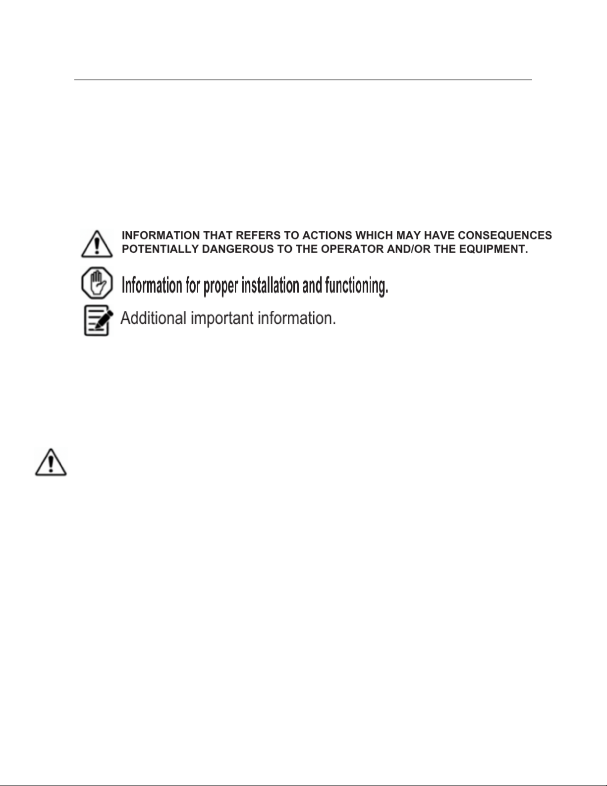
your warranty. To help the reader in the utilization of this manual, certain information has been
highlighted using the following conventions:
1.2. Who Should Install the Equipment
All gas, electrical, and plumbing installations must be performed by a licensed professional.
Only qualified and certified technicians should perform the installation of the Hardt Inferno 2000
Rotisserie to ensure compliance with all local codes and safety regulations.
1.3. Equipment Safety
FAILURE TO CONFORM TO MINIMUM CLEARANCES CAN CAUSE PROPERTY DAMAGE,
INJURY OR DEATH.
Failure to conform to minimum clearances may result in service not being able to be performed!
● Always disconnect power and gas supply before attempting any installation or
maintenance.
● Wear appropriate personal protective equipment (PPE), including safety glasses and
gloves, during unpacking and installation.
● Heavy equipment: Use proper lifting techniques and equipment to avoid injury.
● Ensure the installation area is well-ventilated during and after installation.
● Do not locate the rotisserie in an area where the right (control) side is next to fryers,
broilers or any other appliance that emits grease, smoke, humidity, flour, etc.
● As the venturi for the burner is behind the control panel, precautions should be taken to
prevent the above-mentioned particles from entering the burner and causing it to
malfunction.
● The maximum cooking temperature is approximately 700 degrees Fahrenheit.
Page 5

1.4. Tools & Equipment
(Note: Specific tools and equipment will vary based on the specific installation requirements of
your site, e.g., type of gas connection, electrical setup, etc. This is a general list.)
● Basic hand tools (wrenches, screwdrivers, pliers)
● Level
● Measuring tape
● Pipe wrenches (for gas and plumbing connections)
● Electrical testing equipment (multimeter, voltage tester)
● Cutting tools (for piping, if required)
● Lifting equipment (forklift, pallet jack, or heavy-duty dolly, depending on unit size and
weight)
● Sealant (for gas connections, as per local codes)
● Thread seal tape (for water connections)
● Leak detection solution (for gas connections)
● Flashlight or work light
1.5. Warranty Information
Refer to the separate warranty documentation provided with your Hardt Inferno 2000 Rotisserie
for complete details on warranty coverage and limitations. Improper installation, as defined by
this manual, may void your warranty.
Page 6
2. Equipment Diagrams
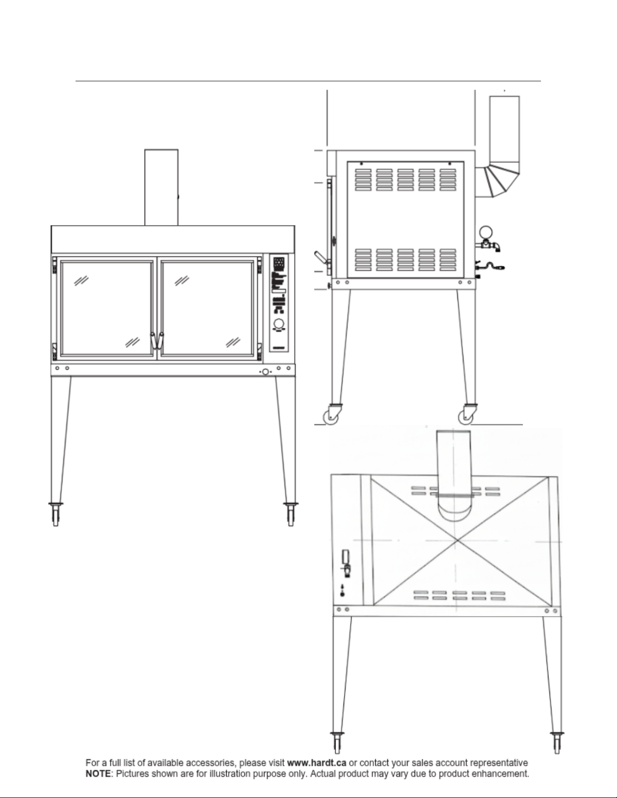
2.1. Single Rotisserie
Page 7
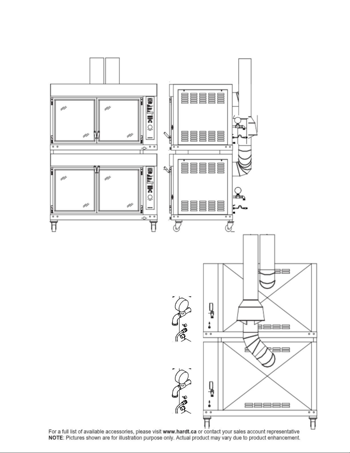
2.2. Double-Stacked Rotisserie
Page 8

3. Receiving and Unpacking
3.1. Packing Checklist
Upon receipt of your Hardt Inferno 2000 Rotisserie, carefully inspect the packaging for any signs
of shipping damage. If damage is observed, document it thoroughly with photographs and notify
the carrier immediately.
Verify that all components listed below are present. Compare the contents of your shipment with
the packing list provided by Hardt Equipment Manufacturing Inc.
● Hardt Inferno 2000 Rotisserie Unit (Single or Top/Bottom for Double-Stacked)
● Rotisserie Spits (quantity as ordered)
● Grease Collector Pans (2 required per oven)
● Chimney Flues (as supplied)
● Grate Sections
● Ceramic Logs
● Strainer (for drain)
● Overflow Strainer with 1½" brass tube
● Rubber Washers (for drain/overflow)
● Drain Elbow
● Overflow Drain Elbow
● Drain Valve
● Instruction Manuals (including this Installation Manual, Operating Manual, etc.)
● Warranty Information
Page 9
3.2. Single Rotisserie
3.2.1. Unpacking
1. Carefully cut and remove any strapping
securing the unit to the pallet.
2. Remove any protective wrapping, plastic
film, or cardboard packaging.
3. Inspect the unit for any visible damage
that may have occurred during shipping. Report
any damage immediately to the carrier and Hardt Equipment.
4. Locate and verify all accessory boxes
and loose components as per the packing checklist (Section 3.1).
3.2.2. Dismounting the Rotisserie from its Pallet
DISMOUNTING THE ROTISSERIE OFF THE PALLET REQUIRES A MULTI-PERSON
TEAM AS THE WEIGHT OF THE ROTISSERIE IS APPROX. 1400 LBS [635 KG]
DO NOT EXERT PRESSURE ON THE DOOR GLASS OR ON PLUMBING
rrrrrrrrr
ASSEMBLIES WHEN HANDLING THE ROTISSERIE.
FOR SAFETY, A QUALIFIED FORKLIFT OPERATOR MUST APPLY COMMONLY
wwwwwAPPROVED OPERATING PRACTICES AND PRECAUTIONS DURING INSTALLATION.
CONTACT OF THE FORK LIFT WITH ANY PART OF THE ROTISSERIE OTHER THAN
ddddd THE LIFTING BRACKET WILL RESULT IN DAMAGE TO THE ROTISSERIE.
WEAR PROPER SAFETY SHOES AND GLOVES.
To facilitate easier pallet dismounting, most customers request an available
eeeeeewooden lifting rig to be used with a forklift. The following instructions describe
eeee how it is used.
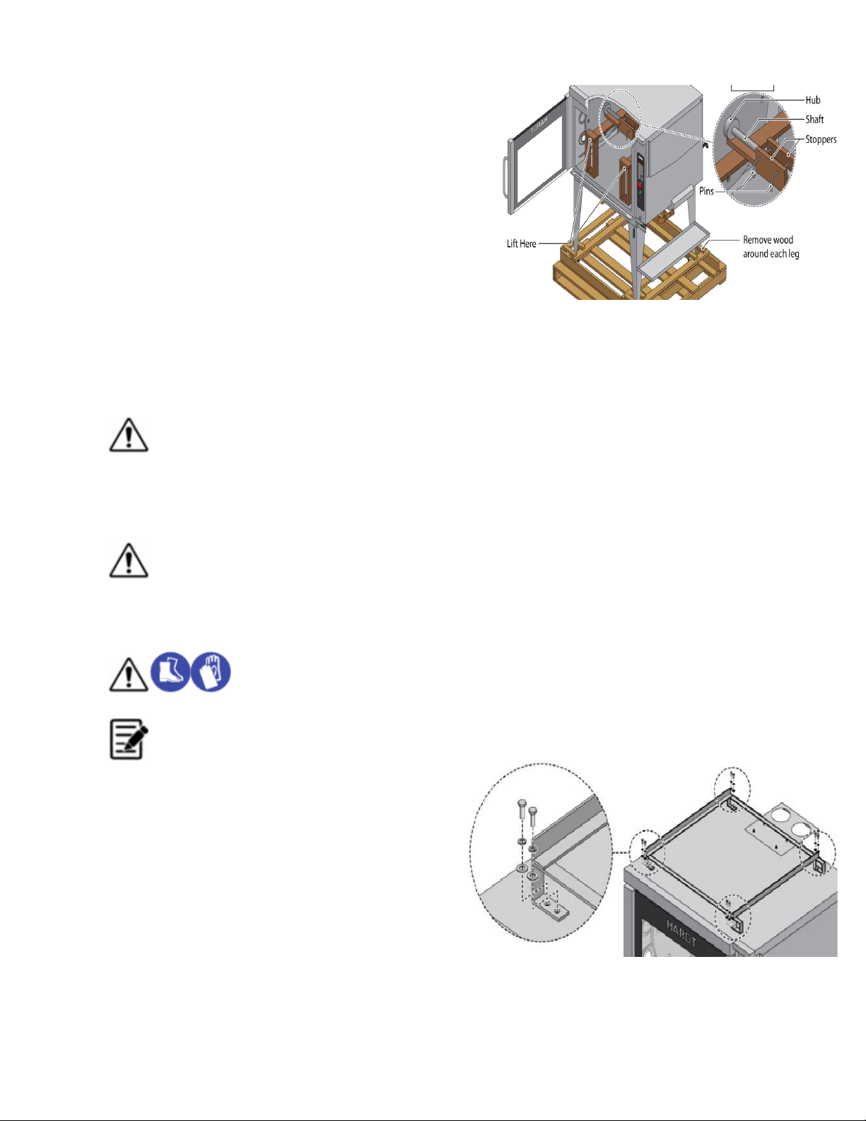
1. Confirm that the top of the rotisserie
has adequate space for the metal lifting
bracket to be positioned.
2. Carefully position the metal lifting bracket
at the top of the rotisserie, taking care not to
damage the top roof of the rotisserie.
(The proper orientation is shown in Figure 3).
3. Align the metal lifting bracket so the shaft is
centered between the two stoppers built into the rig. Figure 4
(This alignment is shown in Figure 4).
Page 10
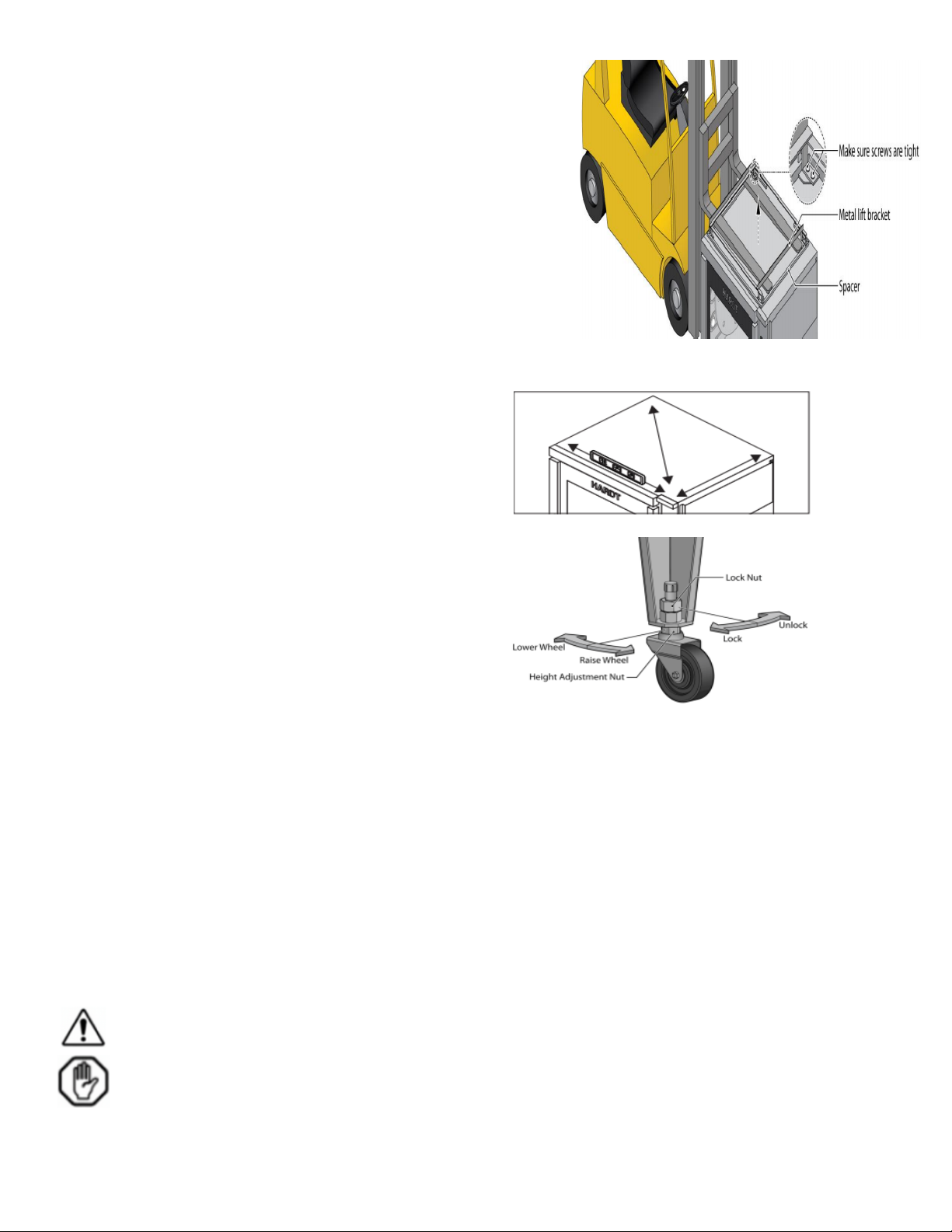
4. Lift the metal lifting bracket slightly and insert the two
pins that hold the metal lifting bracket onto the shaft.
5. Confirm that the metal lifting bracket supports the
rotisserie from the Left and middle of the roof and
NOT from the Right. (Confirm this configuration
as shown in Figure 4 PINS).
6. The rotisserie may now be lifted by inserting the
forklift forks into the openings of the metal lifting
bracket. Lift the rotisserie off its pallet and set it firmly
on the floor (as shown in Figure 5).
7. Carefully remove the wooden lifting rig from the rotisserie. Figure 5
3.2.3. Setting in Place
8. Inspect the rotisserie for any remaining
plastic left over from the manufacturing
and packing process and remove if found.
Be sure to remove the protective foam blocks Figure 6
from the glass doors.
9. Position the rotisserie in the operation area.
10. Verify the rotisserie is level from front to
back and side to side. See Figure 6
11. Raise or lower the feet/optional casters to
level the rotisserie if necessary. See Figure 7. Figure 7
Once the hood installation has been completed the rotisserie can be placed in position. The
rotisserie should be positioned on a level surface. To allow for sufficient cooling the required
minimum clearances to combustible and non-combustible surfaces are:
● Right (Control side): 24"
● Left: 9"
● Front: 30"
● Back: 18"
● Top: 12"
● Vent: 5"
● Flooring: Non-combustible
FAILURE TO CONFORM TO MINIMUM CLEARANCES CAN CAUSE PROPERTY DAMAGE,
INJURY OR DEATH.
Failure to conform to minimum clearances may result in service not being able to be performed!
12. Inside the oven, verify that the Grease Collector Pans
Page 11
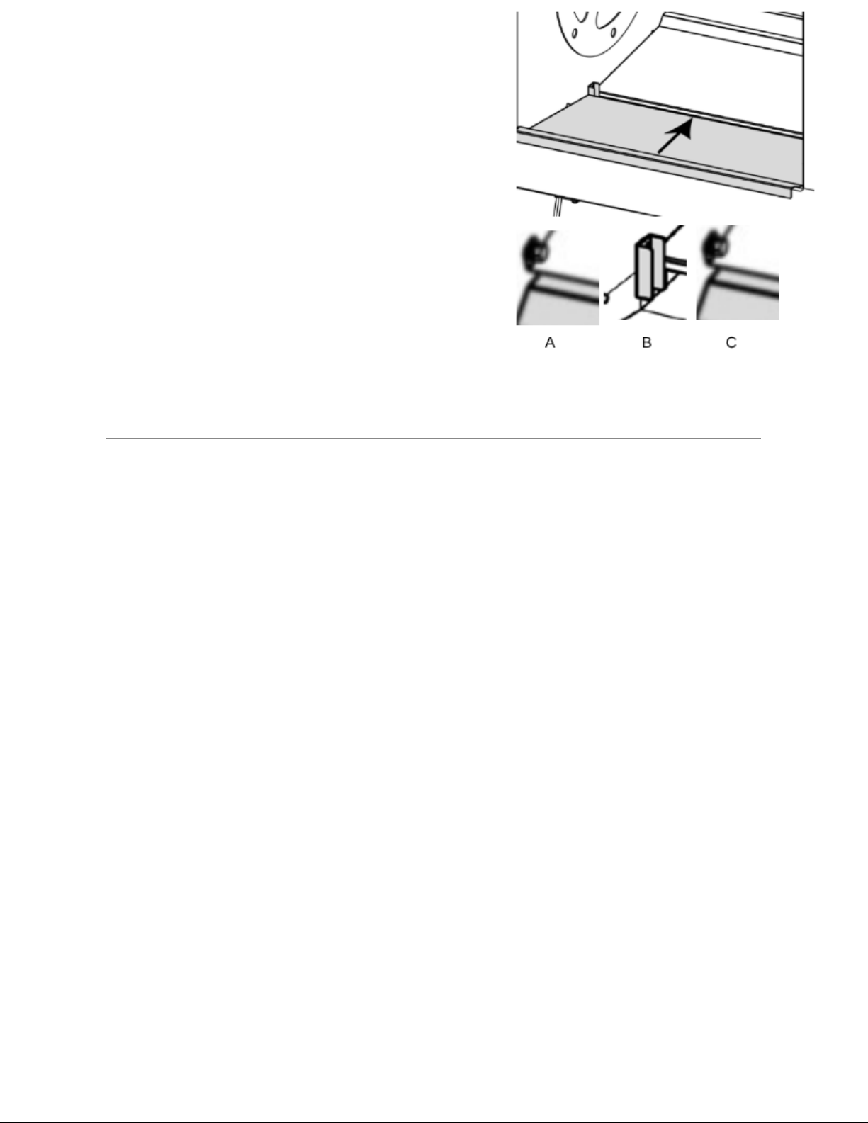
Are secured in place (as they may have dislodged from
their locations during transport).
a. Ensure that the Left Hand tab (A) and slot are
engaged.
b. Ensure that the 2 middle slots (B) are engaged to
their corresponding wall tabs.
c. Ensure that the right hand side of both pans are
positioned behind the stopper (C).
3.3. Double-Stacked Rotisserie
The following instructions will guide you through the process of safely stacking two
Inferno 2000 ovens into a double-stacked configuration.
3.3.1. Unpacking
1. Carefully cut and remove any strapping securing the unit to the pallet.
2. Remove any protective wrapping, plastic film, or cardboard packaging.
3. Inspect the unit for any visible damage that may have occurred during shipping. Report
any damage immediately to the carrier and Hardt Equipment.
4. Locate and verify all accessory boxes and loose components as per the packing
checklist (Section 3.1).
Page 12
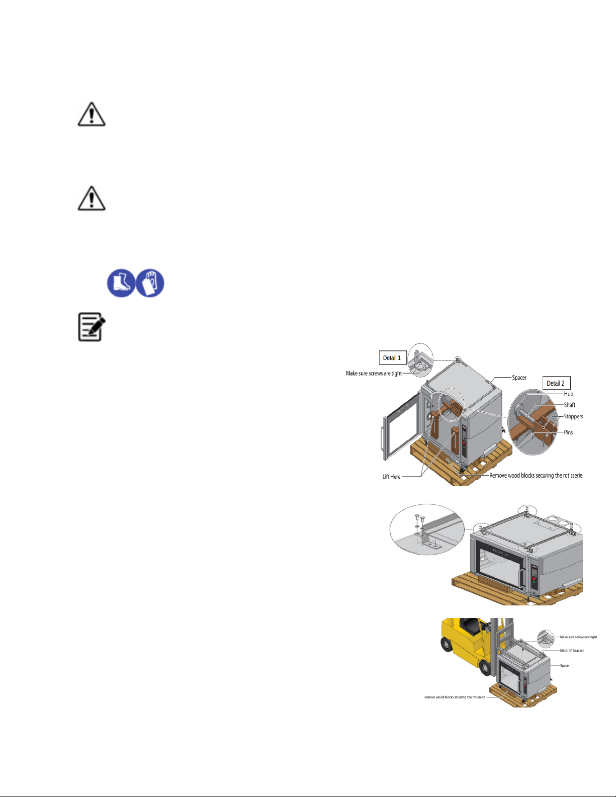
3.3.2. Dismounting the Top and Bottom Rotisseries from their Pallets
DISMOUNTING THE ROTISSERIE OFF THE PALLET REQUIRES A MULTI-PERSON
TEAM AS THE WEIGHT OF THE ROTISSERIE IS APPROX. 1400 LBS [635 KG]
DO NOT EXERT PRESSURE ON THE DOOR GLASS OR ON PLUMBING
rrrrrrrrr
ASSEMBLIES WHEN HANDLING THE ROTISSERIE.
FOR SAFETY, A QUALIFIED FORKLIFT OPERATOR MUST APPLY COMMONLY
wwwwwAPPROVED OPERATING PRACTICES AND PRECAUTIONS DURING INSTALLATION.
CONTACT OF THE FORK LIFT WITH ANY PART OF THE ROTISSERIE OTHER THAN
ddddd THE LIFTING BRACKET WILL RESULT IN DAMAGE TO THE ROTISSERIE.
WEAR PROPER SAFETY SHOES AND GLOVES.
A metal lifting bracket is packaged with the bottom rotisserie. It is used with a
xxxxxxforklift for both pallet dismounting and in the stacking procedure. The following
xxxxxxinstructions describe how it is used.
1. Confirm that the top of the rotisserie
has adequate space for the metal lifting
bracket to be positioned
.
2. Insert the metal lifting bracket on the ct
top roof of the bottom rotisserie, taking
care not to damage the roof. The
proper orientation is shown in Figure 9
3. Align the metal lifting bracket so that the screws Figure 9
are between the two stoppers built into the wooden Figure 9
lifting rig as shown in Figure 10.
4. Lift the metal lifting bracket and insert the four screws
that hold the metal lifting bracket on the roof.
5. As shown in Figure 10, confirm that the metal lifting
bracket supports the bottom rotisserie from the left and
middle and NOT from the right.
6. The bottom rotisserie may now be lifted by inserting the
lift's forks in the openings of the metal lifting bracket. Lift the Figure 10
bottom rotisserie off of its pallet and set it on the floor as
shown in Figure 11.
7. Carefully remove the wooden lifting rig from the bottom
rotisserie and install it into the top rotisserie (the rotisserie
without the casters) using the same instructions.
8. Proceed to section 3.3.3. Stacking the Rotisseries on page 13.
Figure 11
Page 13
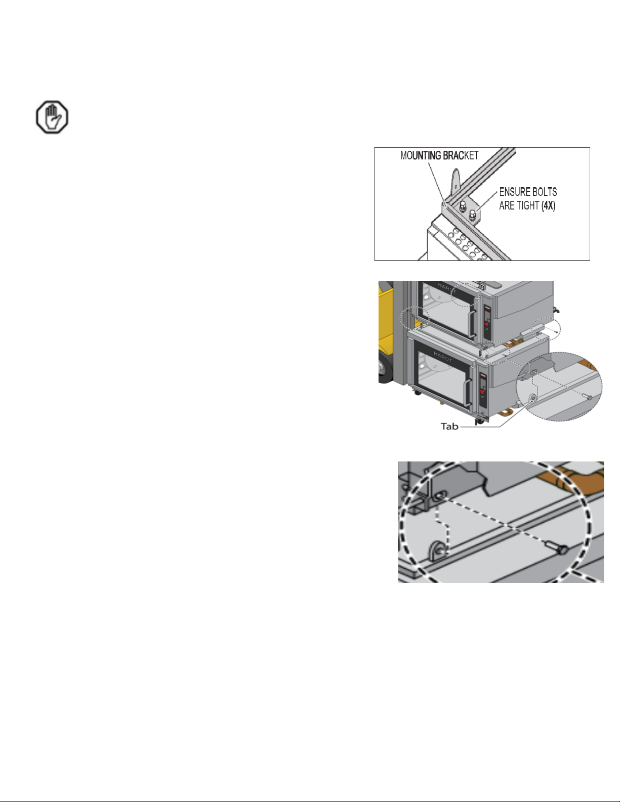
3.3.3. Stacking the Rotisseries
For a rotisserie equipped with casters, the rotisserie must be secured by the restraining
cable device included with the gas hose kit available from Hardt as outlined in section
4.4.3. Attaching the Restrainer Cable on page 21 before stacking the rotisseries
1. Ensure the bolts holding the mounting bracket on
the roof of the bottom rotisserie are tight as shown in
Figure 11.
2. Lift the top rotisserie by inserting the lift’s forks in the
openings of the previously installed wooden lifting rig.
3. Place the top rotisserie on to the bottom one. The four
tabs on the mounting bracket must be inserted inside the Figure 12
frame of the top rotisserie. The holes in the mount of the
top rotisserie must align with the holes in the mounting
bracket tabs of the bottom rotisserie. See Figure 12 and
Figure 13.
Figure 13
4. Install bolts and washers as shown in Figure 13.
5. Carefully back out the forklift from the installation.
6. Remove the wooden lifting from the top rotisserie. Be
careful not to damage the doors or other components of the
rotisseries.
7. Inspect rotisseries for any remaining plastic left over from
the manufacturing and packing process, remove if found. Be Figure 14
sure to remove the protective foam blocks from the glass doors.
Page 14
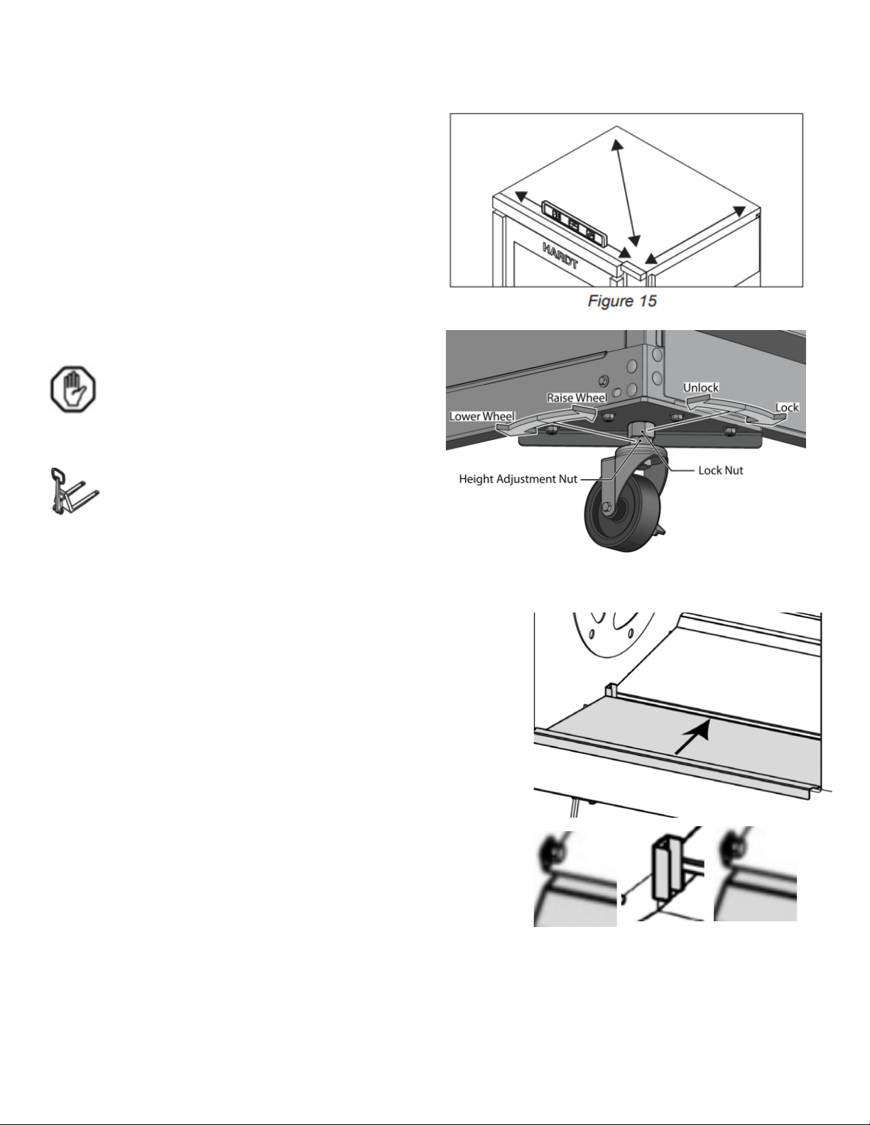
3.3.4. Setting the Rotisseries in Place
8. Manually position the rotisseries close to the
point of operation, leaving space for making
the water, gas and electrical connections.
9. Verify that the double-stacked installation is
leveled from front to back and side to side.
See Figure 15.
10. Raise or lower the casters if necessary.
See Figure 16.
When adjusting, it is necessary to
slightly lift the corner of the doublestacked rotisserie at each caster location
to prevent thread damage.
Hardt recommends the use of a pallet
jack or lever for this procedure.
Figure 16
12. Inside the oven, verify that the Grease Collector Pans
Are secured in place (as they may have dislodged from
their locations during transport).
a. Ensure that the Front Baffle (A) and slot are
engaged.
b. Ensure that the Rear Baffle (B) are engaged to
their corresponding side tabs.
c. Ensure that the right hand side of both pans are
positioned behind the stopper (C).
A B C
Figure 17
Page 15
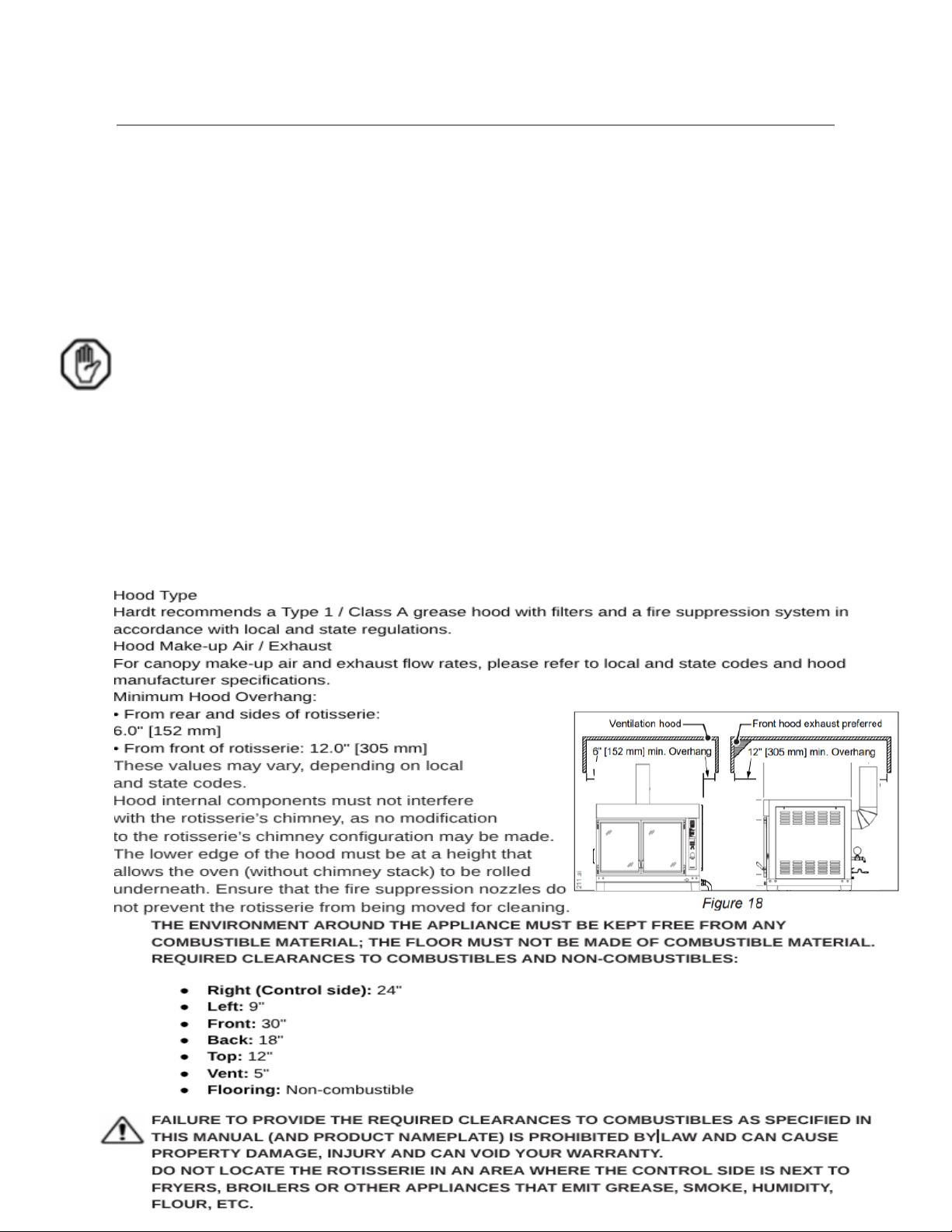
4. Installing the Equipment
Connect the gas, electricity, and plumbing to the rotisserie.
4.1. Venting
The Inferno 4500 rotisserie is designed to be used with a hood or canopy type vent installed by
a qualified professional.
The Inferno 4500 rotisserie must vent with HARDT-supplied flues.
Install the hood and make-up so that air is NOT being blown into nor pulled out of the
rotisserie. The hood should remove exhaust gases without disturbing the air within the
rotisserie
An adequate air supply must be supplied to the rotisserie at all times during operation to
ensure proper flow of combustion and ventilation air
The rotisserie must be installed in a draft-free area where temperatures are above 45°F
[7°C].
Please consult Hardt if further guidance is needed.
4.1.1. Hood Specification Recommendations
Page 16
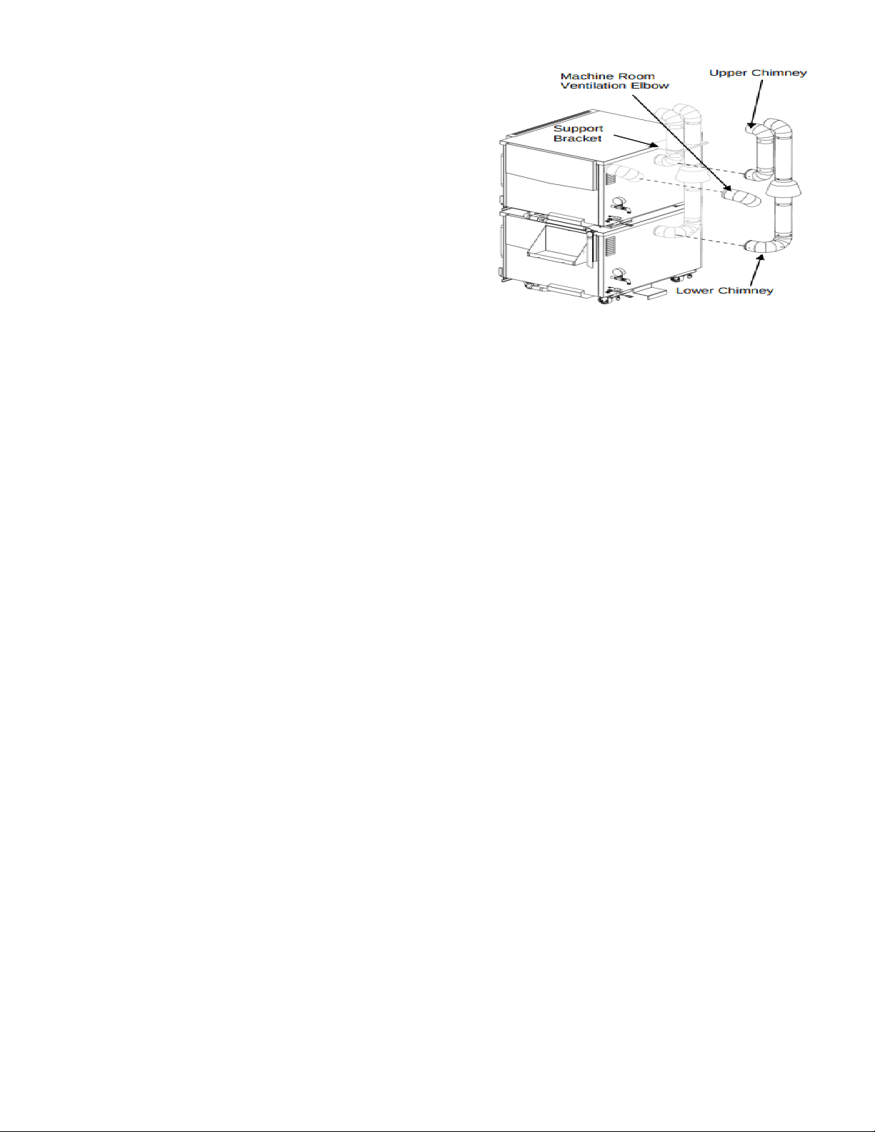
4.1.2. Chimney Installation
1. Connect the supplied chimney flues to the
designated exhaust port(s) on the top of
the rotisserie.
2. Ensure a secure and airtight connection.
3. Connect the chimney flue system to the
overhead Type 1 / Class A grease hood.
4. Follow all local codes and NFPA 96 guidelines
for proper chimney and hood installation,
including fire suppression system integration. Figure 19
Page 17
4.2. Drains
4.2.1. Plumbing the 1.5" [38 mm] grease drain line.
Make sure that the rotisserie is plumbed in a manner which allows the rotisserie to
remain mobile for servicing. The effluent from this drain may contain Fats, Oils and
Greases (FOGs).
Local ordinances may require a backflow prevention device. Consult the authority
having jurisdiction to determine what regulations are in force for appliances of this
type as well as regulations regarding the disposal of grease laden water and FOGs.
Any liquid drained from the rotisserie will be very hot, it is recommended that copper
tubing or other high temperature rated piping be used for the drain connections.
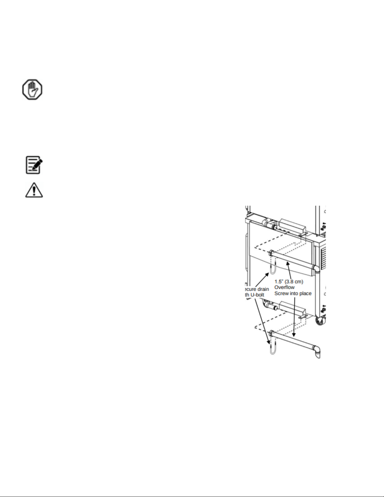
The Inferno 2000 is equipped with two drains (per rotisserie). One drain is for the Main
Drain (1.5" [38 mm] diameter) and the other is for theOverflow Drain Line (1.5" [38 mm]
NPT-M).
THE EFFLUENT THAT DRAINS FROM THE ROTISSERIE CAN BE EXTREMELY HOT.
Drain Installation:
1. There are two holes in the rotisserie's water pan.
The drain hole is the one located in the center of
the rotisserie's water pan.
2. Underneath the rotisserie, place the two rubber
washers onto the flat portion of the drain elbow
and line up the drain elbow with the center hole
of the rotisserie's water pan.
3. Inside the rotisserie, insert the strainer into the
center hole of the water pan and tighten the
strainer into the drain elbow.
4. Attach the drain valve in the location most accessible
to the employees.
5. Connect the drain valve to your facility's waste
plumbing system.
6. When installing a rotisserie equipped with casters,
make sure that the drain is not hard plumbed into
the floor so as to allow the unit to remain mobile Figure 20-a
for servicing.
7. Please consult the authority having jurisdiction
to determine what regulations are in force
regarding the disposal of grease-laden water.
Overflow Installation:
1. The overflow is located in the front of the
rotisserie's water pan.
Page 18
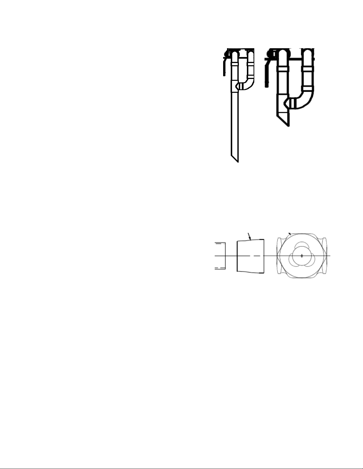
2. Underneath the rotisserie, place two rubber
washers onto the flat portion of the overflow
drain elbow and line it up with the front hole
of the rotisserie's water pan.
3. Inside the rotisserie, insert the overflow strainer
(the one with the 1½" brass tube sticking up) into
the front hole of the water pan and tighten it into
the overflow drain elbow.
4. (If the overflow is connected to the drain pipe it
must only join this pipe after the valve so that the
overflow is free-flowing.)
5. Connect the overflow drain elbow to your facility's
waste plumbing system.
6. Please consult the authority having jurisdiction to
determine what regulations are in force regarding Figure 20-b
the disposal of grease laden water.
4.2.2. connecting the 1.5" [38 mm] drain valve to drains
It is critical to ensure that the drain connection is not hard plumbed into the floor. This
measure allows the unit to remain mobile for servicing and maintenance.
1. Attach the drain valve in a location that is most
accessible to operating employees.
2. Connect the drain valve directly to your facility's
waste plumbing system.
3. For units equipped with casters: It is critical to
ensure that the drain connection is not hard
plumbed into the floor. This measure allows Figure 21
the unit to remain mobile for servicing and
maintenance.
4. Consult the authority having jurisdiction to determine
the local regulations and requirements governing the
disposal of grease-laden water.
Page 19
4.3. Electrical
THE ROTISSERIE IS SUPPLIED WITH A 6.0 FOOT [183 CM] LONG ELECTRICAL CORD.
THE CORD IS EQUIPPED WITH A THREE-PRONG (GROUNDING) PLUG FOR YOUR
PROTECTION AGAINST SHOCK HAZARD AND SHOULD BE PLUGGED DIRECTLY INTO A
PROPERLY GROUNDED THREE-PRONG RECEPTACLE. DO NOT CUT OR REMOVE THE
GROUNDING PRONG FROM THIS PLUG.
THE APPLIANCE MUST BE ELECTRICALLY GROUNDED IN ACCORDANCE WITH LOCAL
CODES OR, IN THE ABSENCE OF LOCAL CODES, WITH THE NATIONAL ELECTRICAL
CODE, ANSI/NFPA 70, OR THE CANADIAN ELECTRICAL CODE, CSA C22.2, AS
APPLICABLE.
IF REQUIRED BY LOCAL REGULATION, A GROUND FAULT CURRENT INTERRUPTER
(GFCI) MUST BE INSTALLED BY A QUALIFIED ELECTRICIAN.
The appliance electrical diagram is located on the inside surface of the right side access panel.
WHEN THE OVEN IS PLUGGED IN, THERE ARE POTENTIALLY DANGEROUS VOLTAGES
PRESENT IN THE CONTROL CIRCUITS.
DO NOT OPEN THE ELECTRICAL COMPARTMENT AS POTENTIALLY LETHAL
VOLTAGES ARE PRESENT INSIDE.
Page 20
4.4. Gas
THE INSTALLATION OF THE GAS SUPPLY MUST BE DONE BY A QUALIFIED PLUMBER
IN ACCORDANCE WITH LOCAL GAS CODES; OR IN THE ABSENCE OF LOCAL CODES
IN ACCORDANCE WITH THE NATIONAL FUEL GAS CODE; ANSI Z223.1/NFPA 54, OR THE
NATURAL GAS AND PROPANE INSTALLATION CODE; CSA B149.1, AS APPLICABLE
INCLUDING:
DURING A PRESSURE TEST OF THE GAS SUPPLY PIPING SYSTEM, THE APPLIANCE
MUST BE COMPLETELY ISOLATED BY DISCONNECTING THE QUICK DISCONNECT GAS
LINE IF THE TEST PRESSURE IS ABOVE 0.5 PSI [3.5 KPA]. IF THE TEST PRESSURE IS
EQUAL TO OR BELOW 0.5 PSI [3.5 KPA], ONLY THE APPLIANCES MANUAL SHUTOFF
VALVE MUST BE CLOSED.
THE ROTISSERIE IS VERY HOT WHEN OPERATING. MAKE SURE THAT THE MAIN GAS
VALVE IS INSTALLED IN A LOCATION EASILY ACCESSIBLE TO THE EMPLOYEES.
ENSURE THE FACILITY GAS SUPPLY IS TURNED OFF BEFORE OPENING ANY
CONNECTIONS PRIOR TO OR DURING THE GAS HOSE INSTALLATION AND
CONNECTION OF THE ROTISSERIE.
A RESTRAINING DEVICE MUST BE INSTALLED SUCH THAT THE ROTISSERIE
MOVEMENT IS LIMITED WITHOUT RELYING ON THE 'QUICK-DISCONNECT' HARDWARE
OR ITS ASSOCIATED PIPING.
It is required that Inferno 2000 rotisseries be equipped with quick-disconnect gas/water
installation hardware.
FOR A ROTISSERIE EQUIPPED WITH CASTERS, IT IS ALSO REQUIRED THAT IT BE
EQUIPPED WITH A CONNECTOR THAT COMPLIES WITH THE STANDARD FOR
CONNECTORS FOR MOVABLE GAS APPLIANCES, ANSI Z21.69 OR CONNECTORS FOR
MOVABLE GAS APPLIANCES, CAN/CSA-6.16, AND A QUICK DISCONNECT DEVICE THAT
COMPLIES WITH THE STANDARD FOR QUICK DISCONNECT DEVICES FOR USE WITH
GAS FUEL, ANSI Z21.41 (CSA 6.9).
4.4.1. Gas Pressure
Natural Gas Incoming Pressure: 7 inches W.C. [1.74 kPa] – 12 inches W.C. [2.99 kPa].
Propane Incoming Pressure: 11 inches W.C. [2.74 kPa] – 12 inches W.C. [2.99 kPa].
4.4.2. Quick Disconnect Flexible Hose
All hardware required for a quick-disconnect gas/water installation may be purchased from
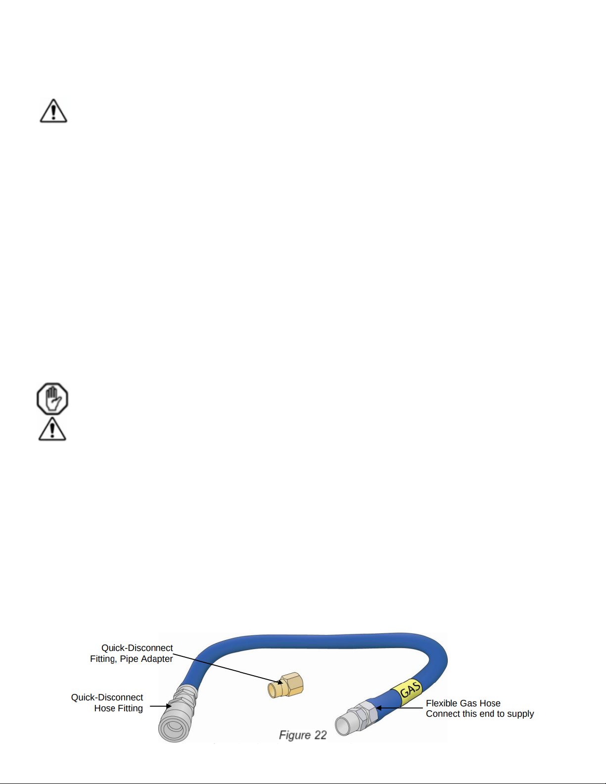
HARDT. The quick-disconnect flexible hose and pipe adapter (both shown in ) are available
from Hardt.
Page 21
4.4.3. Attaching the Restrainer Cable
FOR A ROTISSERIE EQUIPPED WITH CASTERS, THE ROTISSERIE MUST BE SECURED
BY THE RESTRAINING CABLE DEVICE INCLUDED WITH THE GAS HOSE KIT AVAILABLE
FROM HARDT AS OUTLINED BELOW:
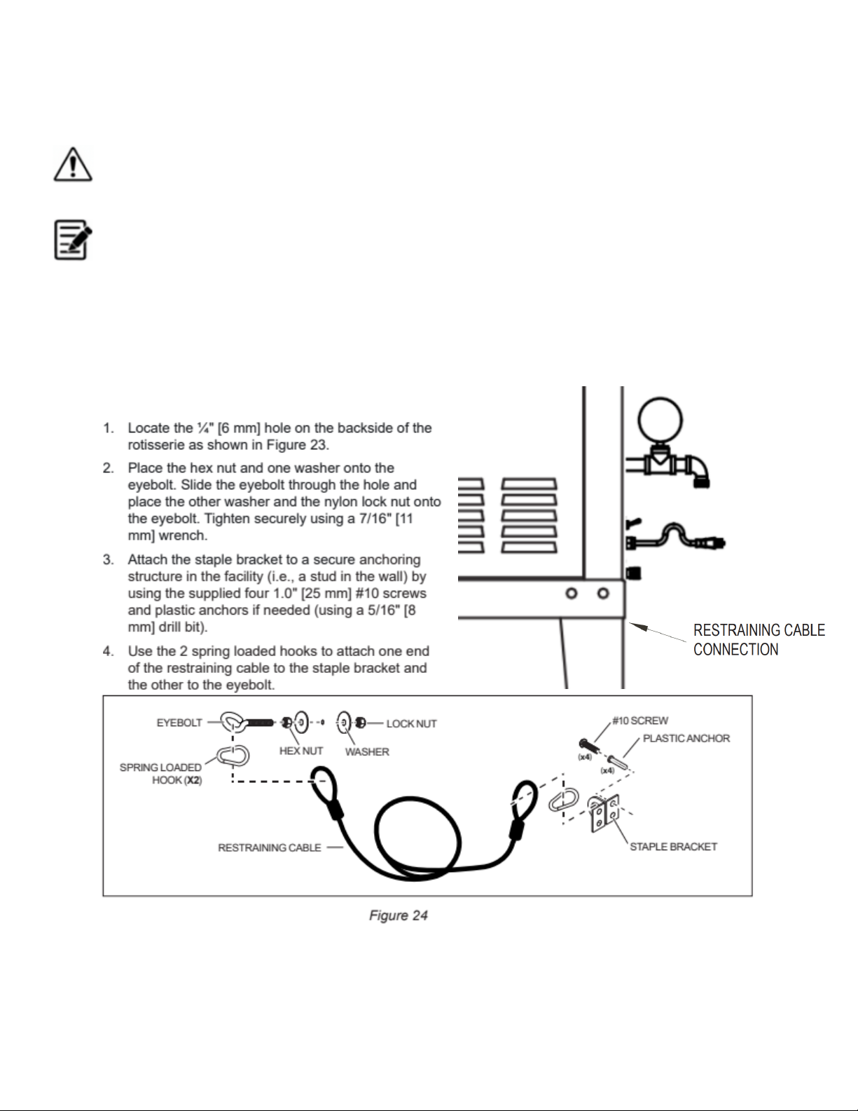
If the rotisserie is a double-stacked, the restraining cable can be installed either on the top or
bottom oven. If the cable is installed on the top oven, it must be installed prior to stacking
the 2 ovens together.
The restraining cable and the staple bracket are
supplied with the quick-disconnect kit (the kit must
be ordered along with the rotisserie, see Figure 24).
The staple bracket must be installed by a qualified
contractor.
Figure 23
Page 22
4.4.4. Making Gas Connections
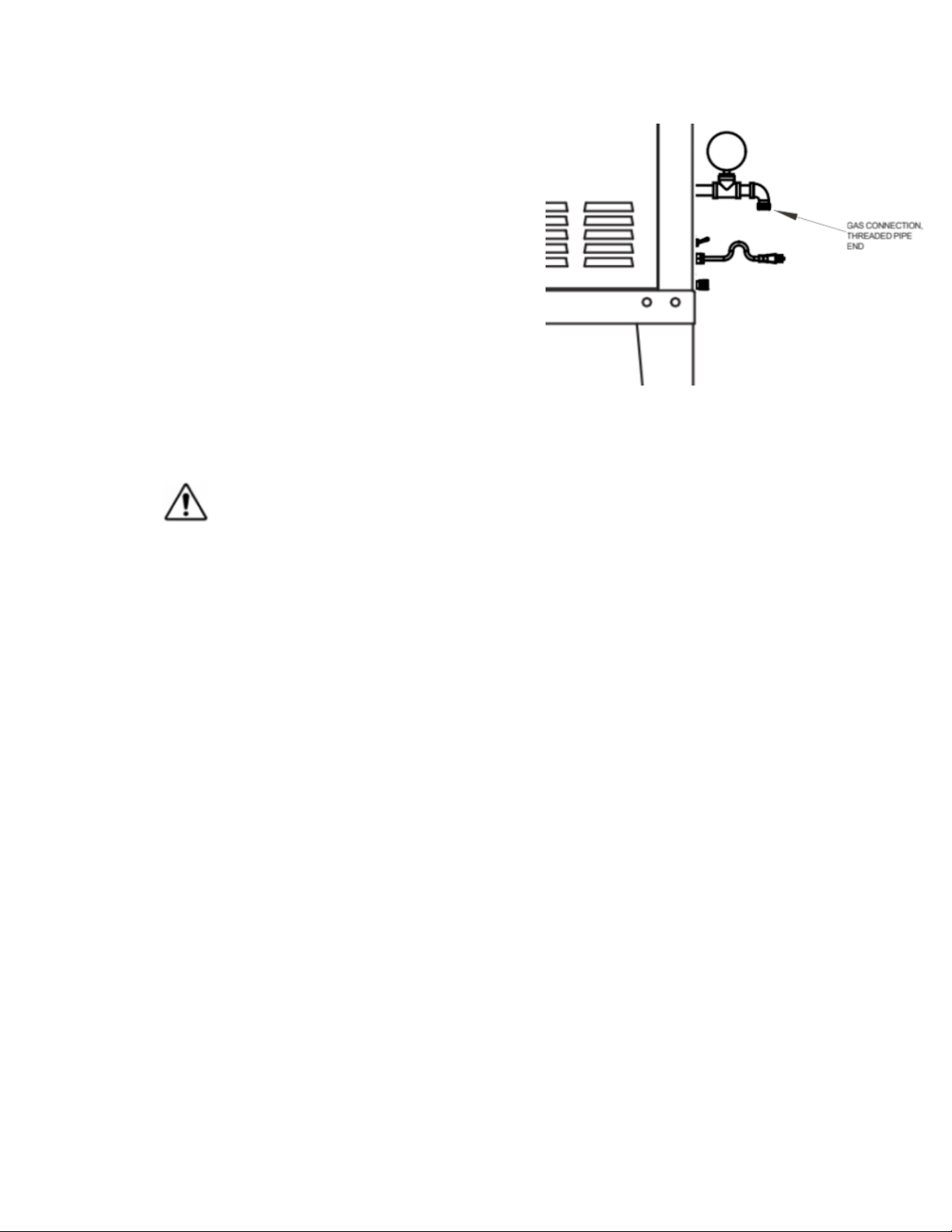
1. The gas connection is located behind the
right rear corner of the rotisserie. See Figure 25.
2. Apply an approved thread sealant to the threaded
pipe end on the gas pipe extending from the rear
of the rotisserie.
3. Screw the Quick-Disconnect fitting (pipe adapter
shown in Figure 22) onto the threaded connection.
4. Attach the flexible gas supply hose to the facility
gas supply line and connect the gas to the rotisserie
by sliding the Quick-Disconnect hose fitting onto the
pipe adapter. Figure 25
5. Open the main gas valve from the facility gas supply line(s).
6. Check all hoses, fittings and connections for leaks prior to
operating the rotisserie.
FAILURE TO CHECK FOR LEAKS MAY RESULT IN INJURY OR DEATH.
Page 23
4.5. Water
The manufacturers’ recommended installation instructions DO NOT supersede any local
plumbing regulations. Installation must be done by a certified tradesman and in
accordance with all code requirements.
Each rotisserie requires a connection to a hot water source. It is recommended that high
temperature rated hoses and pipes are used to provide water to each rotisserie.
Each rotisserie requires a water pressure of 30 – 60 psi [210 - 410 kPa] at inlet.
4.5.1. Water Softener
In locations where the water hardness exceed 4.0 GPG [70.0 PPM] a water softener is
required. External softeners are not required in locations that have integrated water
softening systems in their potable water supply lines. For all other locations it is
recommended that you install an external water softener system. The softener should be
installed on the water supply line to the rotisserie and be connected to the water inlet
located at the back of the rotisserie. DO NOT MOUNT THE WATER SOFTENER DIRECTLY
ON THE ROTISSERIE.
4.5.2. Water Connection
1. Ensure that the facility water
supply is turned off.
2. Locate the water inlet connection
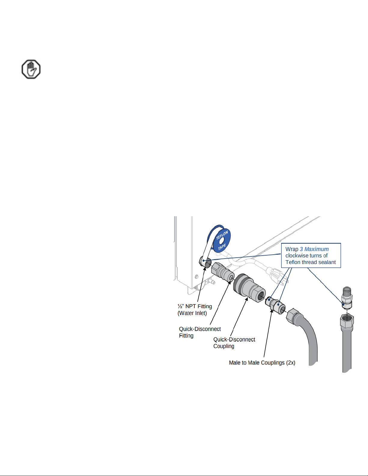
at the lower rear right corner of the
rotisserie (see Figure 26).
3. Connect the rotisserie to the water
supply line by using a flexible hose. If
using the connection kit available from
Hardt, assemble as shown in Figure 26.
WRAP 3 (MAXIMUM) CLOCKWISE
TURNS OF TEFLON TAPE TO ALL
EXTERNAL THREADS.
Notes:
(1) If the rotisserie does not have
casters, it can be connected by using direct
hard plumbing.
(2) Some rotisseries are built with bottom
connections (that differ from the plumbing
location shown in Figure 26) but the setup
and instructions are the same. Figure 26
4. Ensure that the drain valve handle at the
side of the rotisserie is set to ‘OPEN’. Open
the water supply valve and check for leaks.
ALL SUPPLY SIDE WATER FITTINGS MUST BE INSTALLED BY A QUALIFIED PLUMBER.
Page 24
4.6. Installation of Grate Sections and Ceramic Logs
The grates and ceramic logs should be
1.
installed as shown in figure 27.
2. The grate sections should be leaning
against the back inside wall of the unit.
3. The ceramic logs should be placed vertically,
using the locating groove to position them on the grates. Figure 27
Do not use more than 4 ceramic logs at one time within the unit.
4.7. Accessories
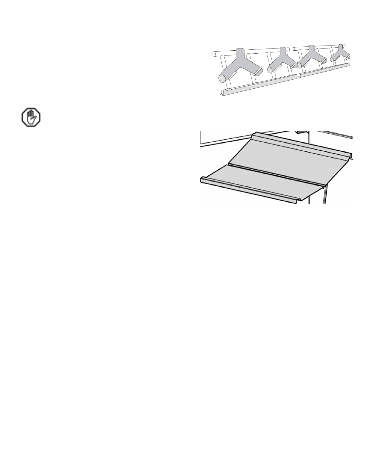
4.7.1. Grease collector pans
1. Place the supplied grease collector pans into
their designated slots or areas beneath the
cooking area. These pans are crucial for
collecting grease runoff during operation
and must be properly installed before use.
Wewkfjwkqjewfklwetk3twkhrkl3 4hFigure 28
Page 25

4.8. Final Checklist
Before operating the Hardt Inferno 2000 Rotisserie, perform the following final checks:
● [ ] All packaging materials have been removed from and around the unit.
● [ ] The rotisserie is positioned on a level surface.
● [ ] All minimum clearances to combustible and non-combustible surfaces have been met
(Right: 24", Left: 9", Front: 30", Back: 18", Top: 12", Vent: 5", Flooring: Non-combustible).
● [ ] The Type 1 / Class A grease hood and chimney flues are properly installed and
connected, without air being blown into or pulled out of the rotisserie.
● [ ] The grate sections and ceramic logs are correctly installed.
● [ ] The 1.5" [38 mm] grease drain line is properly plumbed and connected to the facility's
drainage system, with the drain valve accessible.
● [ ] The 1.0" [25 mm] water inlet drain line (if applicable) is plumbed.
● [ ] The overflow is correctly installed and connected to the facility's drainage system.
● [ ] All electrical connections are made by a licensed electrician, meet code, and are
properly grounded.
● [ ] The gas supply is connected by a licensed professional, all connections are leak-free,
and gas pressures meet specifications (Natural Gas: 7” W.C. min; Propane Gas: 11”
W.C. min).
● [ ] If casters are present, the quick disconnect gas/water hardware is correctly installed.
● [ ] The restrainer cable is securely attached to the rotisserie and anchored to a fixed
point.
● [ ] The water supply is connected, and any necessary backflow prevention device or
water softener is installed.
● [ ] All accessory grease collector pans are in place.
● [ ] Review the operating manual for initial startup procedures and user instructions.
.
 Loading...