

Page 1
Instruction ManualInstruction Manual
Instruction Manual
Instruction ManualInstruction Manual
HH
II
84108410
H
I
8410
HH
II
84108410
Dissolved OxygenDissolved Oxygen
Dissolved Oxygen
Dissolved OxygenDissolved Oxygen
PP
rocess Controllerrocess Controller
P
rocess Controller
PP
rocess Controllerrocess Controller
www.hannainst.comwww.hannainst.com
www.hannainst.com
www.hannainst.comwww.hannainst.com
1
Page 2

Dear Customer,
Thank you for choosing a HANNA instruments® product.
Please read this instruction manual carefully before using the instrument.
This manual will provide you with all the necessary information for
correct use of the instruments, as well as a precise idea of thier
versatility in a wide range of applications.
If you need additional technical information, do not hesitate to e-mail
us at tech@hannainst.com.
TABLE OF CONTENTSTABLE OF CONTENTS
TABLE OF CONTENTS
TABLE OF CONTENTSTABLE OF CONTENTS
Preliminary Examination ............................................................. 3
General Description .................................................................... 3
Functional Description HI 8410 ................................................... 4
DO Probes ................................................................................. 8
Specifications HI 8410 ............................................................... 9
Connections ............................................................................. 10
Operational Guide .................................................................... 12
Taking Measurements with HI 8410 .......................................... 15
Calibration Procedure ................................................................ 16
Diagnostic Tests ....................................................................... 16
LED Indication ......................................................................... 17
Probe Maintenance & Cleaning .................................................. 18
Accessories .............................................................................. 18
Warranty ................................................................................. 19
2
2
Page 3

PRELIMINARY EXAMINATIONPRELIMINARY EXAMINATION
PRELIMINARY EXAMINATION
PRELIMINARY EXAMINATIONPRELIMINARY EXAMINATION
Remove the instrument from the packing material and examine it carefully
to make sure that no damage has occurred during shipping. If there is
any damage, notify your dealer.
The meter is supplied complete with
• Mounting brackets
• Transport splash-proof cover
• Instructions manual.
Note: Conserve all packing material until the instrument has been
observed to function correctly. Any defective item must be
returned in its original packing.
GENERAL DESCRIPTIONGENERAL DESCRIPTION
GENERAL DESCRIPTION
GENERAL DESCRIPTIONGENERAL DESCRIPTION
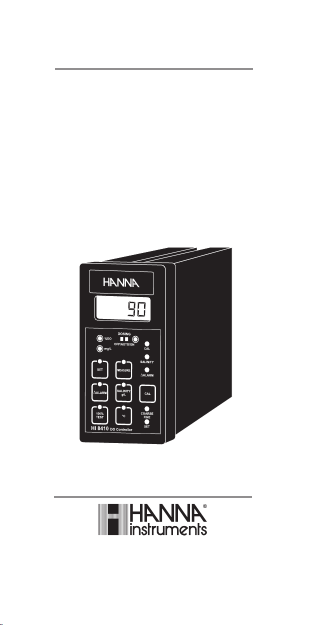
HI 8410 is a panel-mounted DO controller designed for simplicity of
use in a wide range of industrial process applications.
Dissolved Oxygen is indicated in mg/L (ppm) or in % of saturation in
accordance with the selection switch on the back panel. The temperature
can be measured in the range from -5 to 50 °C. The Dissolved Oxygen
readings are automatically compensated for the temperature effects on
the oxygen solubility and membrane permeability. Moreover, the salinity
compensation feature allows the determination of Dissolved Oxygen even
in salty waters.
The instruments are designed with a standard DIN panel mount with
membrane keypads and large LCD with backlight on the front, and
provide a series of auto-diagnostic functions.
Probes, power supply, contacts and recorders are connected on the rear
panel through screw terminals.
For control applications use the HI 76409/4 or HI 76409/10 galvanic probes.
The DO probe is provided with a membrane covering the galvanic sensor
and a built-in thermistor for temperature measurement and compensation.
The Oxygen that passes through the membrane causes an electric current
flow, from which the oxygen concentration is determined.
Other features include: recorder output in 0-20 mA or 4-20 mA configuration;
LED indicators which identify whether the controller is in operation mode or
setup selection mode; overtime control function; hysteresis setting.
The instrument is supplied with a plastic front cover and two mounting
brackets. Power cables are not included.
Note: In order to avoid erroneous readings never use both 0-20 mA
and 4-20 mA recorder outputs at the same time.
3
Page 4
FUNCTIONAL DESCRIPTION HFUNCTIONAL DESCRIPTION H
FUNCTIONAL DESCRIPTION H
FUNCTIONAL DESCRIPTION HFUNCTIONAL DESCRIPTION H
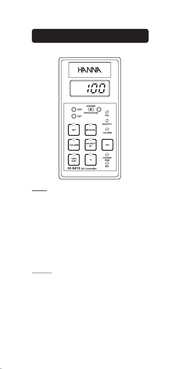
KEYPAD
MEASURE To read measurements and enable diagnostic tests
ΔALARM To display and set the tolerance of the alarm
SET To display and set the working dosing point
SALINITY g/L To display and set the salinity factor (active only
in mg/L range)
CAL To enter in calibration mode
100% TEST Diagnostic function (active only in % DO range)
°C To display the temperature reading
When a key is pressed, the corresponding LED lights up to indicate that the
function is active.
II
I
II
84108410
8410
84108410
TRIMMERS
CAL For 100% DO calibration
SALINITY To set the salinity concentration (g/L)
ΔALARM To set the alarm tolerance
SET COARSE To coarsely adjust the set point
SET FINE To finely adjust the set point
4
Page 5

LEDS
% DO To indicate that the DO is displayed in % of
saturation
mg/L To indicate that the DO is displayed in mg/L
SET To indicate that the dosage is active
ΔALARM To indicate an alarm condition
DOSAGE MODE SWITCH To indicate that the continuous ON or OFF
mode is selected from dosing switch
SWITCHES
OFF/AUTO/ON To select the dosing mode:
• OFF - dosing is disabled
• AUTO - automatic dosage, depending on
setpoint and reading values
• ON - dosing always active
5
Page 6
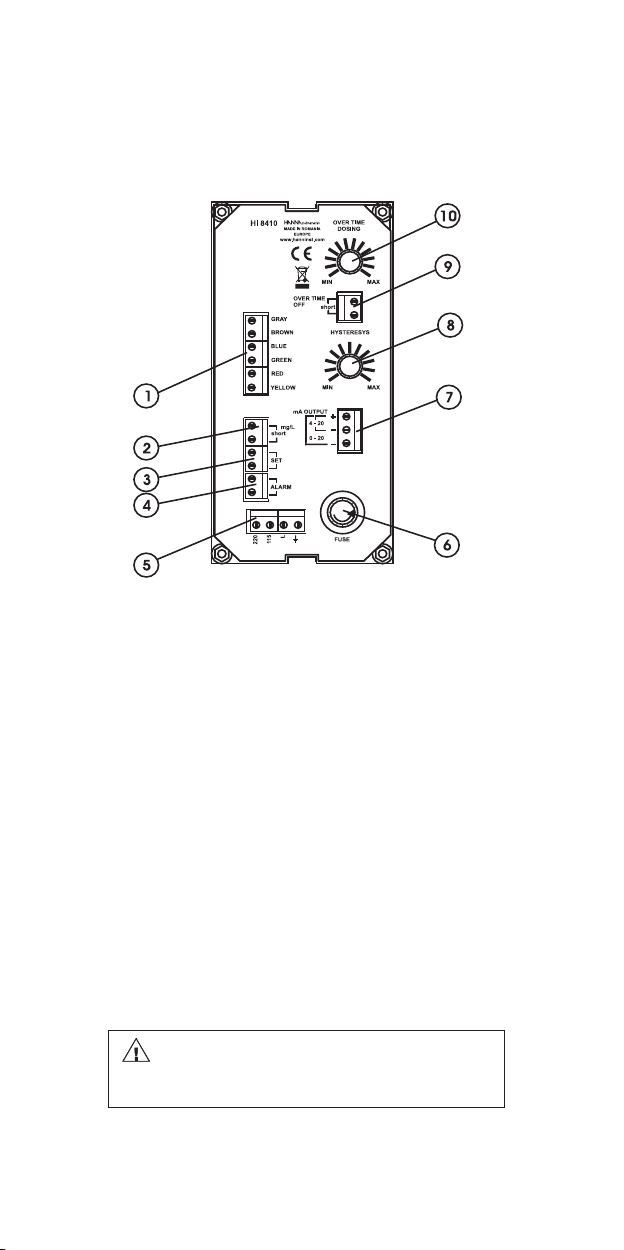
REAR PANEL OF HI 8410
1. DO probe connection terminals
2. Range selection: mg/L or % DO
3. SET terminals for connection to a dosing pump
4. ALARM terminals for connection to an external alarm device
5. Power supply terminals
6. Fuse holder
7. mA OUTPUT terminals for connection to a recorder
8. Hysteresis set knob (0.5 to 2.4 mg/L)
9. Disable overtime dosing connection
10. Overtime dosing set knob (about 5 to 60 min)
Unplug the instrument from power supply before replacing the fuse.
Only one of recorder output connections (0-20 mA or 4-20 mA) can
be used at a moment. Leave unconnected the unused terminal.
6
Page 7

MECHANICAL DIMENSIONS
OF HI 8410
Front view of the panel-mounted unit
These dimensions show the cutout size for the installation.
Side view of the panel-mounted unit
Adjustable location brackets (supplied with the meter) allow the indicator
to slide into the cutout and will hold the unit securely in place. 190 mm
(7.50") is the minimum amount of room required to install the indicator
with the cables connected.
7
Page 8
D.O. PROBESD.O. PROBES
D.O. PROBES
D.O. PROBESD.O. PROBES
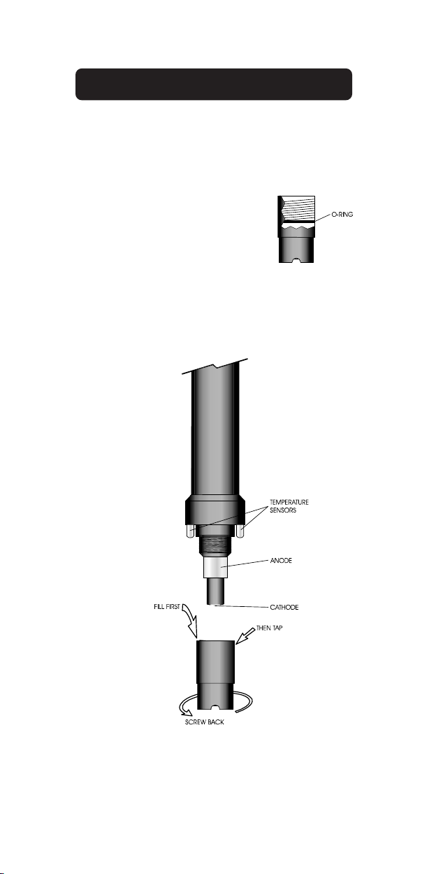
All Hanna DO probes are shipped dry. To hydrate the probe and prepare
it for use proceed as follows:
1. Remove the black & red plastic cap. This cap is used for shipping
purposes only and can be thrown away.
2. Insert the supplied O-ring in the membrane
(see figure).
3. Rinse the supplied membrane (HI 76409A/P) with electrolyte
while shaking it gently. Refill with clean electrolyte. Gently tap
the membrane over a surface to ensure that no air bubbles
remain trapped. To avoid damaging the membrane, do not
touch it with your fingers.
4. With the sensor facing down screw the cap clockwise to the end
of the threads. Some electrolyte will overflow.
8
Page 9

SPECIFICATIONS HSPECIFICATIONS H
SPECIFICATIONS H
SPECIFICATIONS HSPECIFICATIONS H
egnaR
noituloseR O(%1roL/gm1.0
ycaruccA
noitarbilaC riadetarutasni,tniopeno,launaM
noitasnepmoC.pmeT )F°221ot32(C°05ot5-morf,citamotuA
noitasnepmoCytinilaS )L/g1noituloser(L/g15ot0
)dedulcniton(eborP
tuptuOredroceR )detalosi(Am02ot4roAm02ot0
dnayaleRtniopteS
yaleRmralA
egnaRtniopteS
egnaRmralA O)mpp(L/gm0.5ot5.0
egnaRsiseretsyH O)mpp(L/gm4.2ot5.0
lortnoCgnisoD hctiwsnoitceleshtiwNO/OTUA/FFO
lortnoCgnisoDrevO
thgilkcaB NOsuounitnoC
ylppuSrewoP
erusolcnE
tnemnorivnE %59HR;)F°221ot41(C°05ot01-
II
84108410
I
8410
II
84108410
HI76409/4
HI76409/10
)mpp(L/gm0.05ot0.0O
2
O%006ot0
2
C°0.05ot0.5-
C°1.0/)
2
)
O(gnidaerfo%1±
2
rorreeborpgnidulcxeC°2.0±
,daolevitsiser,V042.xaM,A2,detalosi,1
sekorts000,000,1
O%006ot5
2
O)mpp(L/gm0.05ot5.0
2
2
2
bonkhtiwnim06otnim5morf,elbatsujdA
lenaplaerno-partseriwybelbasiDro
%01±;caV032ro511
zH05/06;)elbatcelesresu(
;ydobmunimuladezidonakcalB
;SBAhtiwkcabdnatnorf
revoctnorffoorp-hsalpstnerapsnart
tuotuCelnaP )''7.2x6.5(mm96x141
thgieW ).bl2.2(gk1
9
Page 10

CONNECTIONSCONNECTIONS
CONNECTIONS
CONNECTIONSCONNECTIONS
REAR CONNECTIONS FOR HI 8410
• Power Connection Terminals
4-screw-terminal-strip for connection to
a 3-wire power cable according to the
indicated voltage (115 or 230V).
• Probe Connection
For connection of the HI76409 DO
probe. Connect the wires according with
the indicated color.
• Range Selection
To select mg/L range make a short with
a jumper wire between the terminals (1,
2). To select % DO range leave terminals 1, 2 unconnected.
• Set Contacts
Dosing pumps or other control equipment
may be connected to the "SET" (Max.
2A, 240 V) terminals (3, 4). These
contacts act only as a "dry" switch
allowing electrical continuity, not as a
power supply.
• Alarm Contacts (terminals 5, 6)
During normal operation these terminals
remain closed.
If the measured DO level is not within
the tolerance of the set value, the alarm
contact is open. These contacts act only
as a switch. See also page 15.
• Recorder Output (terminals 1, 2, 3)
These contacts are used for connection
to a recorder output. The output can be
0-20 mA or 4-20 mA and is proportional
to the measured Dissolved Oxygen values.
10
Page 11

Connect the “+” wire from the recorder to terminal 1 on the
instrument and the other wire (common) to terminal 2 for 4-20 mA
recorder output or terminal 3 for 0-20 mA recorder output.
Note: Only one recorder output connection is permited. In order to avoid
malfunction leave unconnected the unused terminal.
• Overtime dosing
When enabled this feature ensures that overdosage is avoided.
Select a desired maximum dosage period. If the dosage relay is
active more than the selected period an alarm condition is activated
and the dosage relay is deactivated.
To leave the overtime dosage alarm status change the position of the
OFF/AUTO/ON switch to OFF and then to AUTO again. The overtime
counter is restarted.
To set the overtime dosing period rotate the overtime knob to the
proper position. The time can be set between approx. 5 min to 60 min
(from MIN to MAX position).
To disable the overtime dosage feature
make a short with a jumper wire between
the terminals of the proper connectors. (see
picture, terminals 1, 2)
• Hysteresis knob
Put the hysteresis knob in the desired position.
The dosage will be active according to the DO
reading, set point value and the hysteresis set
value.
DOSING MODE SELECTION
The DOSAGE switch and the corresponding right side LED on the front
panel are used to select and indicate the dosing mode.
OFF mode
The dosage is disabled. The corresponding
DOSAGE MODE LED blinks (right side of the
switch).
11
Page 12

AUTO
mode
The dosage is activated and deactivated
according with the selected setpoint. The
corresponding DOSAGE MODE LED is off.
Be sure that the DOSAGE switch is in AUTO
position when the meter is in normal
operating mode.
ON mode
The dosage is always activated. The
corresponding DOSAGE MODE LED blinks.
OPERATIONAL GUIDEOPERATIONAL GUIDE
OPERATIONAL GUIDE
OPERATIONAL GUIDEOPERATIONAL GUIDE
INITIAL PREPARATION & INSTALLATION
Material needed:
• a 3-wire power cable to connect HI 8410
Ensure the controller has been calibrated. Ensure the DO probe is
immersed in the sample to be tested.
The DO reading can be displayed in % air saturation or in ppm (mg/L)
according to the range selection. The corresponding LED is ON.
For accurate dissolved oxygen measurements a water flow of at least
5-7 cm/sec is required. In this way a constant replenishment of the
oxygen-depleted membrane surface is ensured.
Accurate readings are not possible in still water.
Note: For some particular applications, such as fish farming, the
membrane can be sterilized with stabilized iodine (20 to 50
ppm), typically used for this purpose.
Note: For use in harsh environments, it is recommended to protect
the membrane with the optional HI 76409-0 sleeve. The
response time will slightly slow down.
12
Page 13

Ensure that the HI 76409 DO probe is
connected to the meter according with the
colors indicated on the mask.
OPERATING INFORMATION
All parameters are set through the front panel keys and trimmers.
When any key is pressed, the corresponding LED lights up to indicate
that the function is active.
SET POINT
To set the working point of the controller, press the SET key. The display
will indicate the current set value.
Use a small screwdriver to adjust the COARSE and FINE trimmers until
the desired value is displayed in units according with the range selected
(the corresponding % DO or mg/L LED is ON).
The dosing will be active when the DO reading is lower than the set point
(set point + hysteresis overpassed = stop dosing; set point = start
dosing).
SALINITY g/L SET (mg/L range only)
Oxygen measurements can be compensated for salinity concentration and
this correction value can be set by the user.
Select the mg/L mode by using the corresponding switch (rear panel).
13
Page 14

Press the SALINITY g/L and the display will show the salinity. Use a small
screw driver to adjust the SALINITY trimmer to display the desired salinity
value (within the 0 to 51 g/L range).
ALTITUDE COMPENSATION (mg/L range only)
When salinity compensation is not required (i.e. not salty water), the
SALINITY trimmer can be used to set the altitude correction value.
Enter the mg/L mode.
Press the SALINITY g/L button. Turn the SALINITY trimmer to display the
salinity value corresponding to the desired altitude.
See below table for reference:
ALARM
Press the "ΔALARM" key and the display
will show the set tolerance for the
alarm.
Use a small screwdriver to adjust the
"ΔALARM" trimmer until the desired
tolerance is displayed.
For example, if the set value is 10 mg/L
and a ΔAlarm of 2 mg /L is set, an alarm
will be activated every time the measured
value is lower than 8 mg/L.
When an alarm occurs, the "ALARM"
LED lights up.
14
Page 15

The alarm contacts of HI 8410 remain closed during normal operation. If
the measured conductivity level is not within the tolerance of the set value,
the alarm contact will be open.
HYSTERESIS SET
Turn the hysteresis knob (rear panel) in the desired position (from 0.5 to
2.4 mg/L range).
The dosage will be active according to the DO reading set point value and
hysteresis set value.
TAKING MEASUREMENTS WITH HI 8410TAKING MEASUREMENTS WITH HI 8410
TAKING MEASUREMENTS WITH HI 8410
TAKING MEASUREMENTS WITH HI 8410TAKING MEASUREMENTS WITH HI 8410
After selecting the range (mg/L or % DO), setting the working point,
hysteresis, salinity factor and alarm value, press the "MEASURE" key. The
DO value of the test solution will be displayed.
If the reading is out of range the instrument displays:
TEMPERATURE MEASUREMENT
Press and hold the "°C" key and the display should indicate the temperature
of the tested solution.
15
Page 16

CALIBRATION PROCEDURECALIBRATION PROCEDURE
CALIBRATION PROCEDURE
CALIBRATION PROCEDURECALIBRATION PROCEDURE
Calibration is a very simple 1-point procedure, performed in air, only in
% DO range.
Ensure the probe is ready for measurements, i.e. the membrane is filled
with electrolyte (see “Probe Preparation” section for details).
If the instrument is set on the % DO range (the mg/L range selection switch
on the rear panel is open) simply turn the CAL trimmer to display 100%.
If the instrument is set on the mg/L range press and hold down the CAL
key to enter % DO range and turn the CAL trimmer to display 100%. After
CAL key is released the instrument returns to mg/L range.
If the environmental relative humidity is lower than
30%, pour some deionized water (approx. 3 mm) in
the white cap supplied with the membrane. Insert the
probe in the cap and calibrate.
Keep the probe in vertical position to avoid any contact
of the membrane with the water.
Note: For best accuracy, calibration should be performed on the measurement
site, and the probe should be at the same temperature as the air.
Note: After replacing the membrane or the electrolyte solution, wait a
few minutes for the reading to stabilize.
DIAGNOSTIC TESTSDIAGNOSTIC TESTS
DIAGNOSTIC TESTS
DIAGNOSTIC TESTSDIAGNOSTIC TESTS
The HI 8410 controllers are designed with built-in diagnostic functions to
enable the user to check and troubleshoot the instrument. The checks
performed are through the front panel keys and can be used to isolate the
cause of malfunction.
Press the "MEASURE" key before proceeding
with the following tests.
100% Test
Press and hold the CAL key and then press the 100% TEST key, the display
should indicate a value in the interval between 30% and 200% DO.
16
Page 17

LED INDICATIONLED INDICATION
LED INDICATION
LED INDICATIONLED INDICATION
All LEDs above the keys or near switches indicate the state of each
function, whether it is active or the display is indicating the mode.
% DO LED It is on if the selected range is % DO.
mg/L LED It is on if the selected range is mg/L..
OFF/AUTO/ON LED It is on when the switch is in OFF (dosage disabled)
or in ON (dosage continuous enabled) position.
SET LED In MEASURE mode it is OFF or blinking (25% ON) in
accordance with the dosage relay status (inactive/
active).
In SET mode it is ON or blinking (75% ON) in
accordance with the dosage relay status (inactive/
active).
ΔALARM LED In MEASURE mode it is OFF or blinking (25% ON) in
accordance with the alarm status (inactive/active).
In ΔALARM set mode it is ON or blinking (75% ON)
in accordance with the alarm status (inactive/active).
MEASURE LED It is ON while the instrument is in MEASURE
mode.
SALINITY g/L LED It is ON while the instrument is in SALINITY set
mode.
100% TEST LED It is ON when the 100% TEST key is pressed.
°C LED It is on when the °C key is pressed and the
temperature is displayed.
17
Page 18

PROBE MAINTENANCE & CLEANINGPROBE MAINTENANCE & CLEANING
PROBE MAINTENANCE & CLEANING
PROBE MAINTENANCE & CLEANINGPROBE MAINTENANCE & CLEANING
For a top performance probe, it is recommended to replace the membrane
every 2 months and the electrolyte once a month.
Proceed as follows:
• Unscrew the membrane by turning it counterclockwise.
• Rinse the supplied spare membrane (HI 76409A/P) with some
electrolyte solution while shaking it gently. Refill with clean
electrolyte.
• Gently tap the membrane over a surface to ensure that no air
bubbles remain trapped.
• With the sensor facing down screw the cap clockwise to the end
of the threads. Some electrolyte will overflow.
If any deposit scales the sensors, gently brush the sensor surface with the
supplied scouring pad, while paying attention to not damage the plastic
body.
ACCESSORIESACCESSORIES
ACCESSORIES
ACCESSORIESACCESSORIES
HI 76409/4 Galvanic DO probe with built-in temperature sensor and
4 m cable
HI 76409/10 Galvanic DO probe with built-in temperature sensor and
10 m cable
HI 76410-0 Protective sleeve for HI 76410 probes series
HI 76410A/P Membrane for HI 76410 probes series, 5 pcs.
HI 7042S Electrolyte solution, 30 ml bottle
HI 710015 Shockproof rubber boot, blue color
HI 710016 Shockproof rubber boot, orange color
HI 731326 Calibration screwdriver (20 pcs)
Hanna Instruments reserves the right to modify the design,
construction and appearance of its products without advance
notice.
18
Page 19

WARRANTYWARRANTY
WARRANTY
WARRANTYWARRANTY
All HANNA instruments® meters are warranted for two years against
defects in workmanship and materials when used for their intended
purpose and maintained according to instructions.
The probes are warranted for a period of one year.
This warranty is limited to repair or replacement free of charge.
Damages due to accident, misuse, tampering or lack of prescribed
maintenance are not covered.
If service is required, contact the dealer from whom you purchased the
instrument. If under warranty, report the model number, date of purchase,
serial number and the nature of the failure. If the repair is not covered by
the warranty, you will be notified of the charges incurred.
If the instrument is to be returned to HANNA instruments®, first obtain a
Returned Goods Authorization Number from the Customer Service
department and then send it with shipment costs prepaid.
When shipping any instrument, make sure it is properly packaged for
complete protection.
Recommendations for Users
Before using these products, make sure that they are entirely suitable for the
environment in which they are used.
Operation of these instruments in residential area could cause unacceptable
interferences to radio and TV equipments, requiring the operator to take all
necessary steps to correct interferences.
The trimmers are sensitive to electrostatic discharges. It is recommended to use
anti-static screwdrivers.
Unplug the instrument from the power supply before replacing the fuse. External
cables to be connected to the rear panel should end with cable lugs.
To maintain the EMC performance of this equipment, use the proper cables.
Any variation introduced by the user to the supplied equipment may degrade the
instruments' EMC performance.
To avoid electrical shock, do not use these instruments when voltages at the
measurement surface exceed 24 Vac or 60 Vdc.
To avoid damages or burns, do not perform any measurement in microwave ovens.
All rights are reserved. Reproduction in whole or in part is prohibited
without the written consent of the copyright owner.
19
Page 20

Hanna Instruments Inc.
Highland Industrial Park
584 Park East Drive
Woonsocket, RI 02895 USA
Local Sales and Customer Service office
Hanna Instruments United States Inc.
Highland Industrial Park
584 Park East Drive
Woonsocket, RI 02895 USA
Tel. (800) 426 6287
Fax (401) 765 7575
www.hannainst.com/usa
Technical Support for customers
Telephone (800) 426 6287
Fax (401) 765 7575
E-mail tech@hannainst.com
Printed in Romania, EU
MAN8410 07/09
20
 Loading...