

Page 1
SALES AND TECHNICAL SERVICE CONTACTS
Australia:
Tel. (03) 9769.0666 • Fax (03) 9769.0699
Instruction Manual
China:
Tel. (10) 88570068 • Fax (10) 88570060
Egypt:
Tel. & Fax (02) 2758.683
Germany:
Tel. (07851) 9129-0 • Fax (07851) 9129-99
Greece:
Tel. (210) 823.5192 • Fax (210) 884.0210
Indonesia:
Tel. (21) 4584.2941 • Fax (21) 4584.2942
Japan:
Tel. (03) 3258.9565 • Fax (03) 3258.9567
Korea:
Tel. (02) 2278.5147 • Fax (02) 2264.1729
Malaysia:
Tel. (603) 5638.9940 • Fax (603) 5638.9829
Singapore:
Tel. 6296.7118 • Fax 6291.6906
South Africa:
Tel. (011) 615.6076 • Fax (011) 615.8582
HI 83749
Turbidity & Bentocheck
Taiwan:
Tel. 886.2.2739.3014 • Fax 886.2.2739.2983
Thailand:
Tel. (662) 619.0708.11 • Fax (662) 619.0061
United Kingdom:
Tel. (01525) 850.855 • Fax (01525) 853.668
USA:
Tel. (401) 765.7500 • Fax (401) 765.7575
For e-mail contacts and a complete list of Sales and Technical offices, please see
www.hannainst.com.
11/05
40
MAN83749R1
www.hannainst.com
1
Page 2

Dear Customer,
Thank you for choosing a Hanna Instruments product. This manual will provide you with the
necessary information for correct use of the instrument.
Please read this instruction manual carefully before using the instrument.
If you need additional technical information, do not hesitate to e-mail us at tech@hannainst.com
or see the back side of this manual for our worldwide sales and technical service contacts.
This instrument is in compliance with
directives.
TABLE OF CONTENTS
WARRANTY ............................................... 2
PRELIMINARY EXAMINATION ...................... 3
GENERAL DESCRIPTION .............................. 4
ABBREVIATIONS ....................................... 5
PRINCIPLE OF OPERATION ......................... 6
MEASUREMENT UNITS............................... 6
SPECIFICATIONS ........................................ 7
FUNCTIONAL DESCRIPTION ........................ 8
GENERAL TIPS FOR AN ACCURATE
MEASUREMENT....................................... 10
CALIBRATION PROCEDURE ....................... 12
TURBIDITY MEASUREMENT ...................... 16
BENTOCHECK (PROTEIN STABILITY TEST) ... 18
DETERMINATION OF BENTONITE
REQUIREMENT ........................................ 20
LOGGING ................................................ 24
GOOD LABORATORY PRACTICE (GLP) ......... 27
SETUP .................................................... 29
LCD BACKLIGHT ....................................... 35
TAG INSTALLATION .................................. 35
LAMP REPLACEMENT ............................... 35
BATTERIES MANAGEMENT ........................ 36
ERROR CODES......................................... 37
PC INTERFACE ......................................... 38
CE DECLARATION OF CONFORMITY ............ 38
ACCESSORIES ......................................... 39
WARRANTY
ACCESSORIES
HI 83749-20 Bentocheck (100 mL)
HI 93703-58 Silicone oil (15 mL)
HI 83749-11 Calibration cuvets kit
HI 731331 Glass cuvets (4 pcs)
HI 731335N Caps for cuvets (4 pcs)
HI 93703-50 Cuvets cleaning solution (230 mL)
HI 731318 Tissue for wiping cuvets (4 pcs)
HI 740220 25 mL glass vial with cap (2 pcs)
HI 731341 Automatic pipette 1000 µL
HI 731351 Tips fo automatic pipette 1000 µL (25 pcs)
HI 740233 Filter paper type II (100 pcs)
HI 740142P 1 mL graduated syringe (10 pcs)
HI 740144P Tips for 1 mL syringe (10 pcs)
HI 740234 Replacement lamp for EPA turbidimeter (1 pcs)
HI 92000 Windows® compatible software
HI 920011 RS232 connection cable
HI 920005 5 tag holders with tags
HI 740027P 1.5V AA battery (12 pcs)
HI 710005 Voltage adapter from 115V to 12 VDC (USA plug)
HI 710006 Voltage adapter from 230V to 12 VDC (European plug)
HI 710012 Voltage adapter from 240V to 12 VDC (UK plug)
HI 710013 Voltage adapter from 230V to 12 VDC (South Africa plug)
HI 710014 Voltage adapter from 230V to 12 VDC (Australia plug)
HI 83749 is warranted for two years against defects in workmanship and materials when used for
its intended purpose and maintained according to instructions. This warranty is limited to repair
or replacement free of charge.
Damage due to accidents, misuse, tampering or lack of prescribed maintenance is not covered.
If service is required, contact the dealer from whom you purchased the instrument. If under
warranty, report the model number, date of purchase, serial number and the nature of the failure.
If the repair is not covered by the warranty, you will be notified of the charges incurred. If the
instrument is to be returned to Hanna Instruments, first obtain a Returned Goods Authorization
number from the Technical Service Department and then send it with shipping costs prepaid. When
shipping any instrument, make sure it is properly packed for complete protection.
To validate your warranty, fill out and return the enclosed warranty card within 14 days from the
date of purchase.
2
Hanna Instruments reserves the right to modify the design, construction and appearance of its products without
advance notice.
39
Page 3
PC INTERFACE
PRELIMINARY EXAMINATION
To fully use the instrument tag identification system function, the measured data has to be
downloaded to a computer. The instrument can use RS232 or USB connection to communicate
with the PC.
When using the RS232 protocol, simply connect a HI 920011 serial cable between the instrument
and the computer.
To use the USB protocol, simply connect a regular USB cable between instrument and PC.
In both cases, the PC must run the HI 92000 application for successful data transfer.
CE DECLARATION OF CONFORMITY
Recommendations for Users
Before using these products, make sure that
they are entirely suitable for your specific
application and for the environment in which
they are used.
Operation of these instruments may cause
unacceptable interferences to other electronic
equipments, this requiring the operator to take
all necessary steps to correct interferences.
Any variation introduced by the user to the
supplied equipment may degrade the
instruments' EMC performance.
To avoid damages or burns, do not put the
instrument in microwave ovens. For yours and
the instrument safety do not use or store the
instrument in hazardous environments.
Please examine this product carefully. Make sure the instrument is not damaged. If any damage
has occurred during the shipment, please notify your dealer.
This HI 83749 Turbidity & Bentocheck Meter is supplied complete with:
• Six Sample Cuvets and Caps
• Four Calibration Cuvets (HI 83749-11)
• Bentocheck Reagent (HI 83749-0) and Silicone Oil (HI 93703-58)
• One 1000 µL Automatic Pipette with two Tips and Instructions Sheet
• Four 25 mL Glass Vials with Caps
• One 1 mL Syringe with two Tips; one Funnel; Filter Paper (25 pieces).
• Five Tag Holders with Tags (HI 920005)
• Tissue for wiping the cuvets
• Four 1,5V AA Batteries
• AC Adapter
• Instruction Manual
• Instrument Quality Certificate
• Rigid carrying case
38
Note:Save all packing material until you are sure that the instrument works correctly. Any
defective item must be returned in the original packing with the supplied accessories.
3
Page 4

GENERAL DESCRIPTION
RORRE NOITPIRCSED NOITCA
;3rrE–1rrE
8rrE;7rrE;6rrE
.srorrelacitirC
.nwodstuhsdnaspeebtnemurtsniehT
tseraenruoytcatnoC
ecivreSremotsuCANNAH
retneC
4rrE
dnaeciwtyltrohsspeebtnemurtsniehT
.sdnoces01retfanwodstuhs
PUylsuoenatlumissserP
teserotNWODdna
PAC .desolctonsidilehT
.dilehtesolC
,stsisreprorreehtfI
tseraenruoytcatnoc
ecivreSremotsuCANNAH
retneC
Lon .thgilonronekorbpmaL
metsyslacitpoehtkcehC
ecalpeR.snoitcurtsborof
.pmaleht
oLL .thgilhguonetoN
metsyslacitpoehtkcehC
.snoitcurtsborof
-OL-
tnerrucrofdesudradnatsehT
.wolootsitniopnoitarbilac
dnadradnatsehtkcehC
.enotcerrocehtesu
-IH-
tnerrucrofdesudradnatsehT
.hgihootsitniopnoitarbilac
dnadradnatsehtkcehC
.enotcerrocehtesu
gniknilbgatyrettaB .wolootsiefilyrettabgniniamerehT .seirettabecalpeR
ttAb
rofdegrahcsidooteraseirettabehT
.stnemerusaemtcerroc
.seirettabecalpeR
GENERAL DESCRIPTION
The HI 83749 is an auto diagnostic microprocessor meter that benefits from Hanna’s years of experience
as manufacturer of analytical instruments.
The meter is especially designed for wine analyses and, beside turbidity measurements, it allows to
make tests to verify protein stability (e.g. Bentocheck).
The instrument compensates wine color to guarantee accurate readings during the vinification process;
also for the darkest red wine samples. The optical system, consisting of a tungsten filament lamp and
multiple detectors, assures long term stability and minimizes the need of frequent calibration. Calibration
can be anyway easily performed at any time in two, three or four points (<0.1, 15, 100 and 500 NTUadjustable calibration points), using the supplied or user prepared standards.
The meter has all necessary GLP (Good Laboratory Practice) functions to allow maximum traceability
of data like a real time clock, log-on-demand (up to 200 measurements), and T.I.S. -Tag Identification
System to give all recorded data a location, time and date stamp.
The meter measures turbidity of samples from 0.00 to 1200 NTU (Nephelometric Turbidity Units) and
is USEPA compliant. In the USEPA measurement mode the instrument rounds the readings to meet
USEPA reporting requirements. It has a continuous measurement mode to verify the settling rate of
suspended matter, and a signal average (AVG) mode to accumulate multiple readings giving a final
average value. The AVG routine is particularly useful to measure samples with suspended particles
with different dimensions.
The HI 83749 has a user-friendly interface, with a large backlit LCD (Liquid Crystal Display). Acoustic
signals and displayed codes to guide the user step by step through routine operations.
This valuable splash proof portable turbidity meter is supplied in a rigid carrying case that offers
protection for harsh environments.
BENTOCHECK
The prevention of protein haze or deposit in bottled white wines is a universal concern and often a
wine needs to be stabilized before bottling. One commonly used stabilization agent is bentonite.
Bentonite is a volcanic clay earth type fining agent (like kaolin). It improves the clarity and stability of
wine but has also negative aspects because of the volume of lees formed, reduction of tannin and
color. Since there are different types and qualities of bentonite with different capacity of protein
removal, it is important to make laboratory trails with the same lot and wetting degree of the bentonite
as that will be used in the cellar.
Protein stabilization is normally not a problem in bottled red wines because of the relatively high
concentration of phenols that binds and precipitates with the instable proteins before bottling. Often
bentonite is added to red wines at a level of about 12 g/hL (1 lb/1000 gal), reducing colloidal
suspended particles thus improving membrane filterability.
Wines with low phenols contents, such as rose, light reds and whites should be checked for protein
stability before bottling. Hanna is offering a rapid test to verify the risk of future protein haze formation.
4
USING AN AC ADAPTER
In laboratory you can use an AC adapter to power the HI 83749. Simply connect the AC adapter to the
instrument (see Connectors Description, page 9).
It is not necessary to turn the instrument off when connecting the external adapter.
Note: The connection to the external adapter will not recharge the batteries.
ERROR CODES
HI 83749 has a powerful diagnostic system. Common errors are detected and reported for easy
diagnostic and maintenance.
37
Page 5
BATTERIES MANAGEMENT
For field measurements, HI 83749 is powered by 4 AA batteries.
The battery life is enough for 1500 normal measurements.
When you turn the instrument on, the remaining battery life is
estimated and reported in percents.
To save the battery life, the instrument will turn off after 15
minutes of non-use. The backlight will be turn off after 25
seconds since the last key was pressed.
The battery life is measured each time the lamp is turned on
and if the remaining battery life is less than 10%, the battery
tag will blink on the LCD to advise the user to replace the
batteries.
When the batteries are completely discharged, “0% bAtt” message
will be displayed for one second and the instrument will turn off.
In order to use the instrument again, replace the batteries or
use an AC adapter.
BATTERIES REPLACEMENT
To replace the batteries follow the next steps:
• Turn OFF the instrument by pressin ON/OFF.
• Open the batteries cover by pressing the locking clip.
If protein instability is detected, a next test can help defining the right amount of bentonite to be
added for improving protein stability. It is important not to overdose bentonite, avoiding stripping
wine flavour, body, and significant loss of color, especially in young red wines. Moreover, adding only
the necessary amount of bentonite to obtain the desired protein stability is also costs saving.
TAG IDENTIFICATION SYSTEM
Hanna is the first manufacturer of turbidity instruments that has decided to add the unique T .I.S. - Tag
Identification System to portable turbidity meters, to meet the more restrictive needs for traceability
and data management of our clients.
The system is designed for scientific and industrial applications, or to prove during safety audits and
inspections that samples have been truly taken on pre-established locations.
The system is as easy to install as to operate. Just fix the so-called
sites that need to be checked often, and with this the T.I.S. is setup. The tag contains a computer chip
embedded in a durable stainless steel can. It is designed to withstand the harsh environments, indoors
or outdoors. The number of tags that can be installed is practically unlimited, because each tag has a
unique identification code.
Immediately after installation of the tags you can start collecting data. Use the meter to take measurements
and memorize the test result by pressing the Log-on-Demand key. Then, the instrument will ask for the
tag identification. Simply touching the
and authenticate logging, by storing the iButton® serial number, time and date stamp events.
The power of the T.I.S. features resides in the PC application. Download all test data to your PC and
use our HI 92000 Windows® compatible application software for further data management. You can
sort or filter all your collected data on different criteria like on a specific sampling location, parameter,
date and time intervals, or fix range to filter measured values. The data can be plotted in a graph,
exported to other common Windows® applications or printed for reporting purpose.
It is also possible to add new tags later on, thus increasing an already existing database. Each time
the PC software recognizes a not already registered tag, it will ask for a description of the new
sampling location.
iButton® with the matching connector on the meter does identify
iButton® tags near your sampling
• Take out the used batteries and insert 4 new 1.5 AA size batteries, paying attention to the correct
polarity as indicated on the battery compartment.
• Replace the cover and press it until it locks.
Warning: Replace batteries only in a non-hazardous area.
36
ABBREVIATIONS
NTU Nephelometric Turbidity Units
FTU Formazin Turbidity Units
USEPA US Environmental Protection Agency
LCD Liquid Crystal Display
RTC Real Time Clock
T.I.S. Tag Identification System
iButton® is registered Trademark of “MAXIM/DALLAS semiconductor Corp.”
Windows® is registered Trademark of “MICROSOFT Corporation”
5
Page 6
UTJ UTF/UTN OiS
2
)L/gm(
UTJ 1 91 05.2
UTF/UTN 350.0 1 31.0
OiS
2
)L/gm( 4.0 5.7 1
PRINCIPLE OF OPERATION
LCD BACKLIGHT
A light beam that passes through the sample is scattered in all directions. The intensity and pattern of
the scattered light is affected by many variables like wavelenght of the incident light, particle size,
shape, refractive index and color.
The optical system includes a tungsten filament lamp, a scattered light detector (900) and a transmitted
light detector (1800). The microprocessor of the instrument calculates the NTU value from the signals
that reaches the two detectors.
The lower detection limit of a turbidimeter is determined by the so called “stray light”. Stray light is
the light detected by the sensors, that is not caused by light scattering from suspended particles.
The optical system of HI 83749 turbidimeter is designed to have very low stray light, providing
accurate results also for low turbidity samples. However, special care must be taken when measuring
low turbidities (see General Tips for an Accurate Measurement, page 10).
MEASUREMENT UNITS
Many methods were used to measure turbidity over the years. The Jackson Candle Turbidimeter was
used to measure turbidity as Jackson turbidity units (JTU). The Secchi Disk is commonly used to
measure turbidity in lakes and other deep waters (mg/L SiO2). Both methods are visual and are not
considered very accurate. To obtain more accurate readings a nephelometer should be used as a
turbidity reading instrument.
The HI 83749 turbidimeter reports the measurements in NTU (Nephelometric Turbidity Units).
NTU units are equal to FTU units (Formazine Turbidity Units). The conversion table between these
measurement units is shown bellow:
The LCD can be illuminated to allow the user to see the readings even in dark
environments.
To turn on or off the backlight, press the ON/OFF key.
The backlight will automatically shut-off after 25 seconds of non-use to save
the battery life.
TAG INSTALLATION
The tag is housed in a rugged metal that can withstand harsh environments. However, it is better
to protect the tag from direct rain.
Place the tag near a sampling point. Fix it securely with the provided screws, in such a way that
the metallic iButton® is easily accessible for reading the tag.
The number of tags that can be installed is practically unlimited. Additional tags can be ordered
(See Accessories, page...) HI 920005 - five tag holders with tags).
LAMP REPLACEMENT
The instrument tungsten lamp has a life longer than 100,000 measurements. In case of lamp failure,
the defective lamp can be easily replaced. When the lamp is broken, the instrument displays “no L”
error message.
To replace the lamp follow the next steps:
• Remove the battery lid.
• Unscrew the lamp connection using a screwdriver.
• Unlock the lamp and extract it by pulling it out
from the lamp holder handler.
• Place the new lamp in the right position and
push it until is securely locked.
• Insert the lamp leads into the connector and
tight them using a screwdriver.
Warning: After lamp replacement the meter needs
to be recalibrated.
6
35
Page 7

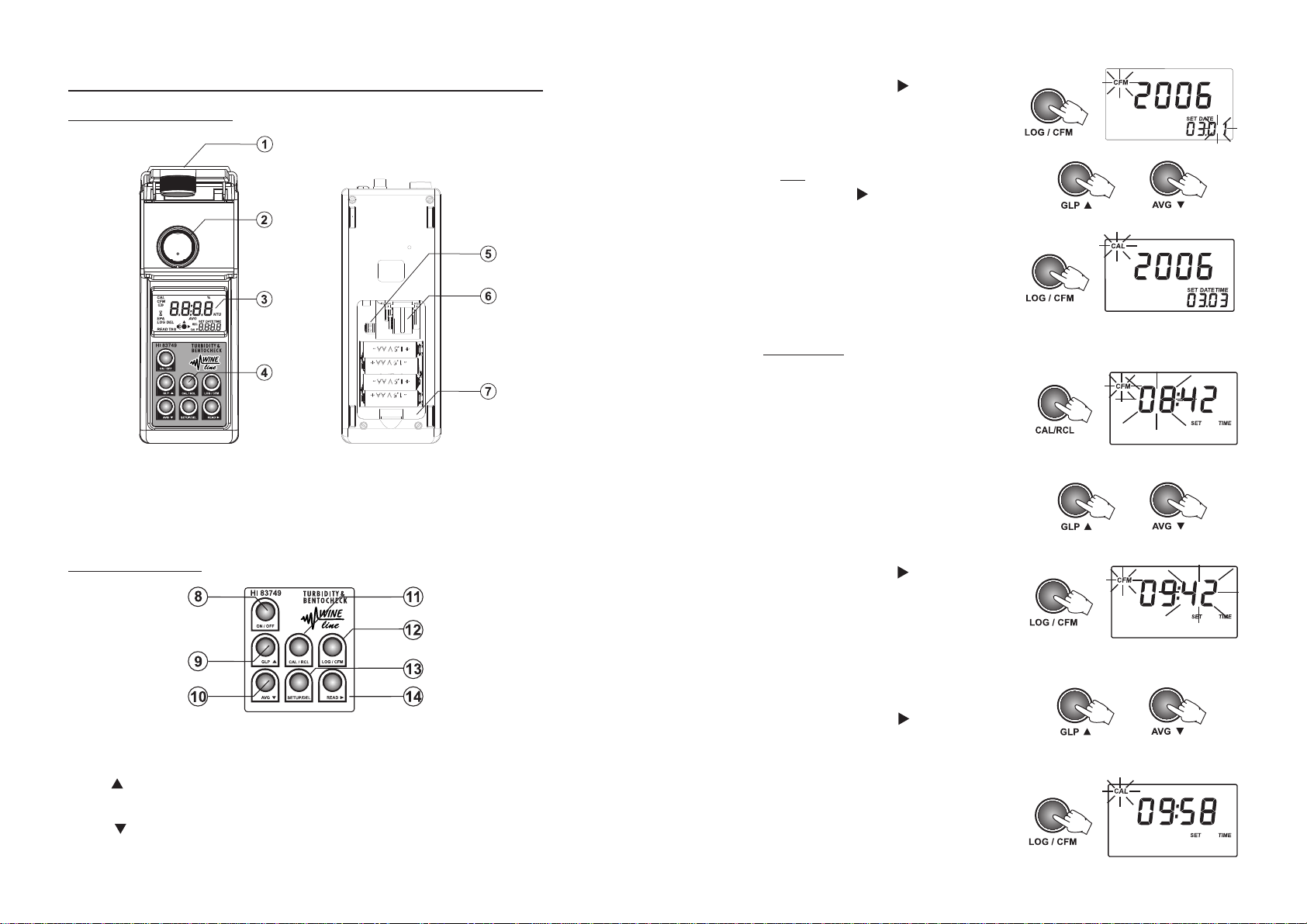
SET INSTRUMENT ID
The instrument ID is a four digit number that can
be edited by the user. The instrument ID is
downloaded on the PC application, together with
the logged data. By setting a different ID for each
instrument it is possible to mix information from
many turbidimeters into the same database.
• To set the instrument ID, press CAL/RCL when
the “Set instrument ID” panel is displayed.
The default instrument ID is 0000. The existing
ID value and the CFM tag will start blinking.
• Press the UP or DOWN keys to set the new
instrument ID. By pressing and holding the UP
or DOWN keys, the changing speed wil increase.
• Press LOG/CFM to save the change. The new
instrument ID will be displayed.
Alternatively, press CAL/RCL to exit without
saving the changes.
SET BAUD RATE
The HI 83749 has a RS232 and a USB link. When
the USB connection is used, the RS232 connection
becomes inactive.
To successfully communicate with the PC, the same
baud rate must be selected on the instrument and
on the PC application. The available baud rates are
1200, 2400, 4800 and 9600.
SPECIFICATIONS
Range 0.00 to 9.99 NTU
10.0 to 99.9 NTU
100 to 1200 NTU
Range Selection Automatically
Resolution 0.01 NTU from 0.00 to 9.99 NTU
0.1 NTU from 10.0 to 99.9 NTU
1 NTU from 100 to 1200 NTU
Accuracy ±2% of reading plus 0.05 NTU
Repeatibility ±1% of reading or 0.02 NTU, whichever is greater
or
Stray Light < 0.05 NTU
Light Source Tungsten filament lamp
Light Detector Silicon Photocell
Method Ratio Nephelometric Method.
Display 60 x 90mm backlit LCD
Calibration Two, three or four points calibration
LOG Memory 200 records
Serial Interface RS232 or USB 1.1
Environment 0 to 50°C (32 to 122°F); max 95% RH non-condensing
Power supply 4 x 1.5V AA alkaline batteries or AC adapter
Auto Shut-off After 15 minutes of non-use
Dimensions 224 x 87 x 77 mm (8.8 x 3.4 x 3.0”)
Weight 512 g (18 oz.)
• To set the baud rate, press CAL/RCL when the
“Set baud rate” panel is displayed.
The parameter value and the CFM tag will start
blinking.
• Press the UP or DOWN keys to select the new
baud rate value.
• Press LOG/CFM to save the change. The new
selected baud rate will be displayed.
Alternatively, press CAL/RCL to exit without
saving the changes.
34
or
7
Page 8
FUNCTIONAL DESCRIPTION
INSTRUMENT DESCRIPTION
1) Cuvet Lid.
2) Cuvet Holder.
3) Backlit Liquid Crystal Display (LCD).
4) Splash proof keypad.
5) Lamp connector.
6) Lamp Holder.
7) Battery Compartment.
• Press LOG/CFM or READ
day value. The day value will start blinking.
• Press the UP or DOWN keys to set the day value.
Note: to edit the year again, after the day was
set, press READ .
• Press LOG/CFM to save the new date. The new
date will be displayed on the LCD. Alternatively,
press CAL/RCL to exit without saving the changes.
to start editing the
SET THE TIME
• To set the current time, press CAL/RCL when the
“Set time” panel is displayed. The time format
is hh:mm. The hour value and “CFM” tag will
start blinking.
• Press the UP or DOWN keys to set the hour value.
or
or
KEYPAD DESCRIPTION
8) ON/OFF: this is a bi-funcional key. Just press to turn the instrument on or to activate the back
light. Hold the key for 3 seconds to turn the instrument off.
9) GLP
10) AVG : press to select the AVG (Signal Average Mode) on and off. In Setup it is used to
: press to enter/exit GLP (Good Laboratory Practice) feature. In Setup this key is used to
increase the set values. In Log Recall it is used to select a new record (scroll up).
decrease the set values. In Log Recall it is used to select a previous record (scroll down).
8
• Press LOG/CFM or READ
minutes. The minutes value will start blinking.
• Press the UP or DOWN keys to set the minutes
value.
Note: To edit the hour again, after the minutes
were edited, press READ
• Press LOG/CFM to save the new time. The new
set time will be displayed.
Alternatively, press CAL/RCL to exit without
saving the changes.
to start editing the
.
or
33
Page 9

SHOW / HIDE THE TIME
You can choose between showing or hiding the
current hour and minutes on the secondary LCD.
• To set hiding or showing the time, press
CAL/RCL when the “Show/hide time” panel is
displayed.
The time show status and the CFM tag will start
blinking.
• Press the UP or DOWN keys to set Lcd / hide for
time.
• Press LOG/CFM to save the change. The new
selected option will be displayed on the LCD.
Alternatively, press CAL/RCL to exit without
saving the changes.
SET THE DATE
The HI 83749 turbidimeter has a built-in real time
clock (RTC). The RTC time is used to generate a
unique time stamp for each recorded value and to
automatically store the last calibration date. The
current time can be displayed on the LCD when the
instrument is in measurement mode.
11) CAL/RCL: this is a bi-functional key. Just press to enter/exit calibration or in setup mode to
start/stop editing a parameter. Hold the key for 3 seconds to enter/exit viewing log content.
12) LOG/CFM: press to save a record or to confirm the selected option.
13) SETUP/DEL: press to enter/exit setup. The DEL function is available in Log Recall mode to
delete one or all records. In GLP it is used to restore factory calibration.
14) READ
or
: press to start a measurement. Hold the key to make a continuous measurement. In
Log Recall mode it is used to view the content of a record. In GLP it is used to view all
available information. In Setup, during date or time editing, it is used to select day, month or
year and hour/minutes.
CONNECTORS DESCRIPTION
15) AC adapter connector.
16) RS232 connector, to be used with serial
cable to trasfer data to PC.
17) Tag reader.
18) USB connector.
DISPLAY DESCRIPTION
• To set the current date, press CAL/RCL when the
“Set date” panel is displayed. The date format
is YYYY.MM.DD. The last two digits of the year
value and CFM tag will start blinking.
• Press the UP or DOWN keys to set the year value.
• Press LOG/CFM or READ
month value. The month value will start
blinking.
• Press the UP or DOWN keys to set the month
value.
to start editing the
32
1) Battery icon. This icon appears when the status of the battery is displayed or when the battery
voltage is getting low.
2) Hour glass icon. It is displayed when the instrument performs an internal checkup.
3) Lamp and read status indicator.
or
4) Four digit main display.
5) NTU measurement units. When average or continuous mode is selected, the “NTU” tag blinks
for each new displayed value. For conversions in other units see Measurement Units section.
6) AVG icon appears when the Signal Average Mode is selected.
7) Four digit secondary display.
BEEPER
or
A long beep indicates an error or an invalid key pressed. A short beep means that the current
operation is confirmed.
9
Page 10

GENERAL TIPS FOR AN ACCURATE MEASUREMENT
The instructions listed below should be carefully followed to ensure best accuracy.
GENERAL TIPS
• Always cap the cuvets to avoid spillage of the sample into the instrument.
• Always close the lid of the instrument during measurement.
• Keep the lid of the instrument closed when it is not used to prevent dust or dirt entering.
• Put always the instrument on a flat, rugged surface when taking measurements.
CUVET
The cuvet is part of the optical system and measurements can be affected by the glass imperfections,
dirt, dust, scratches, or fingerprints present on the cuvet surface.
CUVET HANDLING
• Any cuvet with visible scratches must be discarded.
• Always store the cuvets in separate boxes or with separators between them to avoid scratches on
the surface.
• Whenever a cuvet is placed into the instrument, it must be dry outside, free of fingerprints or
dirt. Wipe it thoroughly with HI 731318 (tissue for wiping cuvets, see Accessories Section,
page 39) or a lint-free cloth prior to insertion.
CUVET OILING
•
For low turbidity readings (<1.0 NTU) the cuvets should be oiled outside with the supplied
HI 93703-58 Silicone Oil. Use only one single drop of oil and then wipe the cuvet thoroughly
with
a lint-free cloth.
SET EPA COMPLIANCE MODE
When EPA compliance reading is on, “EPA” message
is displayed on the secondary LCD and the reported
values are rounded to meet EPA reporting
requirements.
• To edit the EPA mode, press CAL/RCL when EPA
compliance reading panel is displayed.
The parameter setting and “CFM” tag will start
blinking.
• Press the UP or DOWN keys to set the EPA
compliance mode on or off.
• Press LOG/CFM to save the setting. The new
selected option of the parameter will be
displayed on the LCD.
Alternatively, press CAL to exit without saving
the new settings.
SET BEEPER
The HI 83749 has a built-in beeper that signals
the tag read, the key press and the error conditions.
The beeper can be selected to be on or off.
or
SAMPLING TECHNIQUE
When you make turbidity measurements it is important to take a representative sample.
• Gently mix the sample before filling the cuvet.
• Samples should be analyzed immediately after collection because turbidity can settle or change in
time.
• Pay attention when working with cold samples that no condense is formed on the outside of the
cuvet. We recommend to work always with samples at room temperature.
10
• To set the beeper on or off, press CAL/RCL when
set beeper panel is displayed.
The beeper status and the CFM tag will start
blinking.
• Press the UP or DOWN keys to set the beeper on
or off.
• Press LOG/CFM to save the change. The new
selected option will be displayed on the LCD.
Alternatively, press CAL to exit without saving
the changes.
or
31
Page 11

• Add HI 83749-0 Bentocheck reagent, mix and
wait for 1 minute. Then take a new reading (T2).
• If the difference between T1 and T2 is less than
10%, the instrument gives a beep of 1 second
and displays alternating the turbidity value
(NTU) and the difference (%).
alternated with
REMOVING AIR BUBBLES
Air bubbles present in the sample will cause erroneous high turbidity readings.
• To remove air bubbles fill the cuvet with wine sample and close the cap tightly. Shake the
cuvet gently to create pressure. Allow the cuvet to stand for a few minutes and gently invert it
several times. Check that no air bubbles are visible, otherwise shake again and repeat the
procedure above.
• Alternatively use an ultrasonic bath to degas the wine sample.
• If the difference between T1 and T2 is more
than 10%, the instrument just displays T2 in
the primary LCD and T1 in the secondary LCD.
ACTIVATING COMPARATIVE MODE
For the determination of bentonite requirement you
can activate Comparative mode for an automatic
comparison of turbidity values.
• To edit the Comparative mode, press CAL/RCL
when “Activating Comparative mode” panel is
displayed.
The parameter setting and “CFM” tag will start
blinking.
• Press the UP or DOWN keys to set the
Comparative mode on or off.
• Press LOG/CFM to save the setting. The new
selected option will be displayed on the LCD.
Alternatively, press CAL/RCL to exit without
saving the new settings.
MEASUREMENT TIPS
• For a correct filling of the cuvet: the liquid in the cuvet forms a
convexity on the top; the bottom of this convexity must be at the
same level of the 10 mL mark.
• For dosing the Bentocheck reagent, we recommend to
supplied Hanna automatic pipette
For a correct use of the Hanna automatic pipette, please follow
the related Instruction Sheet.
• In order to measure the exact volume of bentonite suspension with the 1 mL syringe, push the
plunger completely into the syringe and insert the tip into the solution. Pull the plunger up to
above the 0.0 mL mark. Take out the syringe and clean the outside of the syringe tip. Then,
adjust the plunger to the 0.0 mL mark (the lower edge of the seal must be exactly on the 0.0 mL
mark). Be sure that no drops are hanging on the tip of the syringe, if so eliminate them.
Then, to add exactly 0.25 mL of bentonite suspension, keep the syringe in vertical position over
or
the cylinder and push the plunger down until the lower edge of the seal is exactly on the 0.25 mL
mark. Now the exact amount of 0.25 mL has been added to the cylinder, even if the tip still
contains some solution.
Repeat the entire procedure to measure 0.50 mL, 0.75 mL and 1 mL of bentonite suspension.
(HI 731341 - 1000 µL).
use the
Hanna
automatic pipette
Note: when Comparative mode is set on, in the
Measurement mode, the secondary display will
show the reference value
30
or
0.25 mL 0.50 mL
11
Page 12
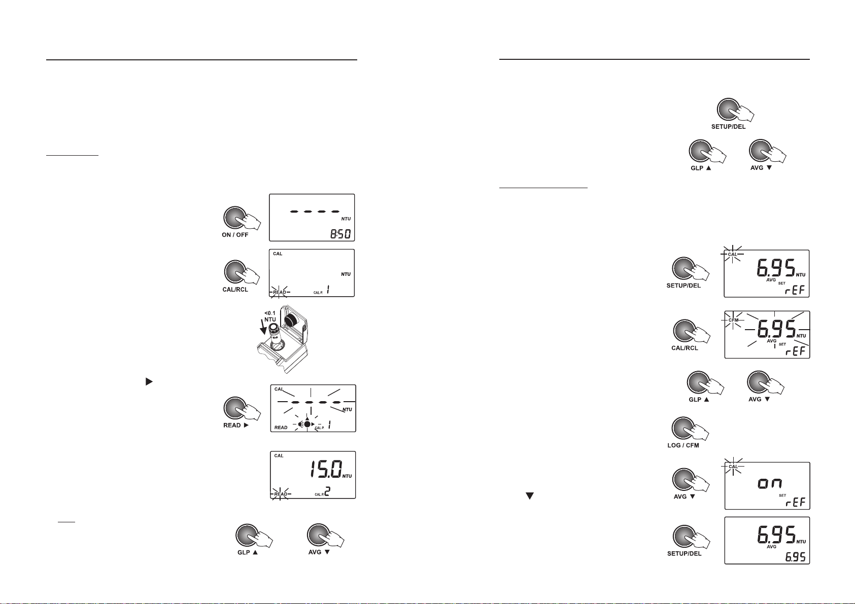
CALIBRATION PROCEDURE
SETUP
It is recommended to calibrate the meter only with Hanna ready-to-use calibration standard solutions.
Alternatively, formazin standards can be used. The prepared formazin solutions should be close
to the default calibration points. The first point must be near 0 NTU, the second point between
10 and 20 NTU, the third point between 50 and 150 NTU and the fourth point between 400
and 600 NTU.
CALIBRATION
Calibration can be performed in two, three or four points. It is possible to interrupt calibration procedure
at any time by pressing ON/OFF.
• Turn the instrument on by pressing ON/OFF.
When the LCD displays “----”, the instrument
is ready.
• Enter calibration mode by pressing CAL/RCL.
The display will show “CAL P.1”.
• Place the <0.10 NTU standard cuvet into the
holder.
The Setup mode allows the user to view and modify the instrument parameters.
The blinking “CAL” tag appears during setup mode suggesting to press CAL for editing parameters.
• To enter/exit SETUP, press SETUP/DEL.
• To select the parameter to be edit, press UP or
DOWN keys until the desired panel is displayed.
or
SET REFERENCE VALUE
During determination of bentonite requirement for
stabilization of the wine, it can be useful to set a
reference value and let the instrument automatically
compare turbidity values.
• When the display shows the first reading (T1),
you can store the result as Reference Value. Press
SETUP/DEL to enter the “Set Reference Value”
panel. “CAL” will blink and “SET rEF” will be
displayed.
• To set the reference value, press CAL/RCL. Then
the value and “CFM” tag will start blinking.
• Close the lid and press READ
“Lamp and Read Status” indicator will blink
on the display.
Alternatively, press LOG/CFM to skip the first
calibration point.
• Then the LCD will show the second calibration
point (15.0 NTU) and “CAL P.2”, while “READ”
is blinking.
Note: If you’re using different calibration
standards, change the displayed value by
pressing UP or DOWN keys until the display
shows the desired value.
. “----” and the
12
• At this point the displayed reference value can
be modified using the UP and DOWN arrow keys.
• Press LOG/CFM to store the value.
Note: To exit without saving the reference value,
press SETUP/DEL and the meter will return to
the measurement panel.
• To activate the Comparative mode, press the
AVG key and set on the Comparative mode
(see page 30).
or
• Press SETUP/DEL to return to Measurement
mode. The display will show the reference value.
29
or
Page 13
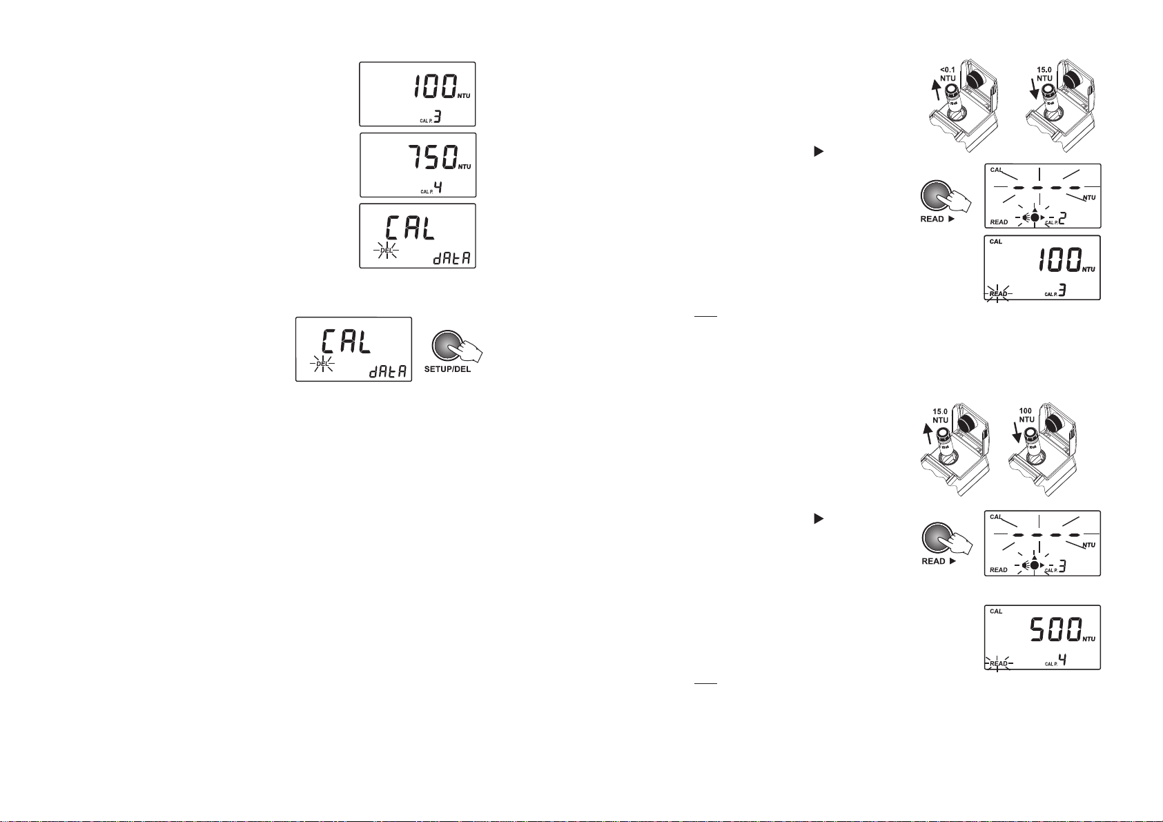
• Third calibration point (if available).
• Remove the <0,10 NTU standard cuvet and
place the 15.0 NTU standard cuvet into the
holder.
• Fourth calibration point (if available).
• Delete calibration panel.
To delete calibration:
• Press SETUP/DEL when the instruments displays
the “Delete calibration” panel.
The user calibration will be deleted and the factory
calibration will be restored. The instrument will
enter automatically in idle mode.
• Close the lid and press READ
“Lamp and Read Status” indicator will blink
again while making the reading.
• At the end of the reading, the third calibration
point (100 NTU) and “CAL P.3” is displayed. If
desired, the value can be changed using the
UP or DOWN keys.
Note: At this moment it is possible to exit
calibration by pressing CAL/RCL. The instrument
will memorize the two-point (<0.10 and 15.0
NTU) calibration data and will return to
measurement mode.
• Remove the 15.0 NTU standard cuvet from the
meter and place the 100 NTU standard cuvet
into the holder.
• Close the lid and press READ
“Lamp and Read Status” indicator will blink
again while making the reading.
. “----” and the
. “----” and the
28
• At the end of the reading, the fourth calibration
point (500 NTU) and “CAL P.4” is displayed. If
desired, the value can be changed using the
UP or DOWN keys.
Note: At this moment it is possible to exit
calibration by pressing CAL/RCL. The instrument
will memorize the three-point (<0.10, 15.0
and 100 NTU) calibration data and will return
to measurement mode.
13
Page 14

• Remove the 100 NTU standard cuvet from the
meter and insert the 500 NTU standard cuvet
into the holder.
• The instrument asks for confirmation. Press the
LOG/CFM key to confirm all records are deleted.
To abort the delete function, press READ
instead of LOG/CFM.
• Close the lid and press READ
“Lamp and Read Status” indicator will blink
again while making the reading.
• At the end of the measurement, the four-point
calibration is completed and the instrument
returns automatically to measurement mode.
OUT CAL RANGE FUNCTION
The instrument has an Out Cal Range function to
alert the user (with “cal” blinking message) when
a measurement is made outside of the calibration
range.
. “----” and the
CALIBRATION ERRORS
• If the read value during calibration is too far
from the set value, the instrument will show
“-LO-” or “-HI-” error.
• After all records are deleted the instrument
returns to measurement mode.
GOOD LABORATORY PRACTICE (GLP)
The GLP feature allows the user to view last calibration data. Also the user calibration can be deleted.
• Press GLP to enter or exit GLP data consulting.
Several functions are available when in GLP
menu.
Press READ to scroll through the GLP data.
The following GLP panels can be viewed.
• The last calibration date, in YYYY.MM.DD
format. If no calibration was performed, the
factory calibration message, “F.CAL”, will be
displayed on the LCD.
or
• The time of the last calibration in hh:mm format.
or
• If the calculated calibration coefficients are off
specifications, the “CAL Err” message is
displayed.
14
• First calibration point: 0.00 NTU if skipped or
the actual read value (e.g. 0.01 NTU).
• Second calibration point.
or
27
Page 15

• Measurement date in YYYY.MM.DD format.
• Measurement time in hh:mm format.
DELETE CALIBRATION
HI 83749 is factory calibrated. It is possible to
restore factory calibration by deleting last performed
calibration.
To delete last calibration, follow the next steps:
• Enter the GLP feature by pressing GLP
The date of the last calibration will be displayed
on the LCD (e.g. 2005.02.23).
.
• Delete the last record panel (only for last record).
• Delete all records.
DELETE LAST RECORD
To delete the last record, scroll through the log menu
until the delete last record panel is displayed.
• To delete the last record, press SETUP/DEL when
the “Delete last records” panel is displayed.
• The instrument asks for confirmation. Press the
LOG/CFM key to confirm the last record is
deleted. To abort the delete function, press
instead of LOG/CFM.
READ
• After the record is deleted, the instrument goes
immediately to the first panel of the previous
record. If the log becomes empty, “----” will be
displayed for one second and the instrument
will return to measurement mode.
• Press READ
related to calibration. The last panel is the one
with “Delete Calibration”.
• Press SETUP/DEL to delete the current
calibration. After deletion the instrument will
automatically return to measurement mode and
the factory calibration is restored.
to scroll through the information
DELETE ALL RECORDS
To delete all records, scroll through the log until
delete all records panel is displayed.
• To delete all records press SETUP/DEL when the
“Delete all records” panel is displayed.
26
15
Page 16

TURBIDITY MEASUREMENT
Note: For wine analysis it is recommended to
work always with the AVG mode on.
• Turn the instrument ON by pressing ON/OFF.
• When the LCD displays “----”, the instrument
is ready. The current time appears on the
secondary LCD, if selected in Setup menu.
• Fill a clean, dry cuvet with 10 mL of wine up to
the mark, taking care to handle the cuvet by
the top. Replace the cap.
Note: To remove any fingerprints or dirt, wipe
the cuvet thoroughly with a lint-free cloth. If
necessary, apply HI 93703-58 Silicone Oil (see
General Tips for an accurate measurements,
page 10), recommanded only if low turbidity
values need to be read.
• Place the cuvet into the instrument and close
the lid.
• Press READ
display.
• At the end of the measurement, the instrument
directly displays turbidity in NTU.
and “----” will blink on the
VIEW LOGGED DATA
The stored records can be viewed at any moment
by keep CAL/RCL key pressed for a few seconds. To
return to normal measurement mode, press RCL
again .
LOG SEARCHING
The log records are stored in chronological order.
The first displayed record is the last stored one.
• Press UP or DOWN keys to scroll the log memory
record by record. By keeping pressed the UP or
DOWN keys, the scrolling speed will increase.
The scrolling of the log is possible from any panel
of the record, except “Delete last log” and
“Delete all logs” panels.
• When scrolling the log, the number of the record
is displayed for one second on the secondary
LCD together with “TAG” if the identification of
the sampling location was made.
When the end of the log is reached, an error beep
is heard.
RECORD VIEWING
Each record contains more information than the
measured value. The additional information is
grouped in several panels.
Press READ
The record panels are displayed one by one in a
circular way.
Each record contains the following panels:
• The record value (turbidity value) and record
number.
Note: If the logged sample value is an over range
• The hexadecimal string of the tag for the
sampling location ID.
Note: If the ID data are missing, “----” is
to scroll through the record panels.
reading, the maximum value (1200) will
be displayed blinking.
displayed instead.
or
16
25
Page 17
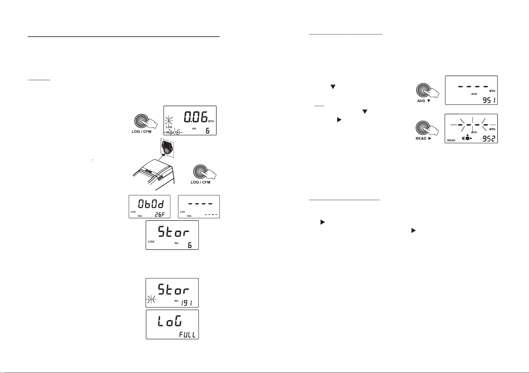
LOGGING
HI 83749 has a log space for up to 200 records. With each measurement, the date, time and tag ID
is stored. In this way, each record is fully characterized and can be easily analyzed when downloading
data on the PC application (HI 92000).
AVG (SIGNAL AVERAGE MODE)
It is recommanded to select this measurement mode when you work with unstable samples that
contain suspended particles of different dimensions.
In the AVG mode the instrument takes 20 measurements in a short period of time and displays the
updated averaged value.
LOGGING
The log function is active after a valid measurement
is obtained (no errors).
• To log a value, press LOG/CFM when the
measurement result is displayed.
The instrument asks to READ TAG for identification
of the sampling location. The location for the new
record is also displayed on the secondary LCD.
• To read the ID code for the sampling location
identification, simply touch the
the matching connector, located on the back of the
instrument (see Connectors Description, page 9).
Alternatively, press again LOG/CFM to store the
record without the tag ID code.
• If the tag is successfully read, the instrument will
beep once, displaying the unique hexadecimal
code of the tag, and store the data.
After data is stored, the instrument returns to
measurement mode.
Notes: • If the tag is not read within 20 seconds,
the logging procedure is canceled.
• A measurement can be stored only once.
Also an over range value can be stored.
iButton
®
tag with
• To select the averaged measurement mode press
the AVG
the LCD.
Note: to return to the normal measurement mode
just press again the AVG key.
• Press READ
play. After a few seconds the instrument displays
the first reading. The meter continues updating
the readings until the “Lamp and Read Status”
indicator turns off. The final displayed value is
the averaged reading of turbidity in NTU.
or
key and the AVG icon will appear on
and “----” will blink on the dis-
CONTINUOUS MEASUREMENT
or
This measurement mode can be used to verify how fast suspended parts settle out. Please verify first
that the AVG mode is turned off (see instructions above). To make continuous measurement keep the
key pressed until the desired number of measurements are taken.
READ
The last value remains on the display after the READ key is released.
• If less than ten free records are available, the
“LOG” tag will blink while storing data.
• If the log memory is full, the “LoG FULL” message
will appear for a few seconds on the LCD and the
instrument will return to measurement mode
without storing the new record.
To store a new record, delete one or more records.
24
17
Page 18

BENTOCHECK (PROTEIN STABILITY TEST)
• Turn the instrument ON by pressing ON/OFF.
When the LCD displays “----”, the instrument
is ready.
Note: On the secondary LCD the current time
appears, if selected in Setup menu.
• Select the AVG mode by pressing the AVG
key. The AVG icon will appear on the display.
• Fill a clean, dry cuvet with 10 mL of wine up to
the mark, taking care to handle the cuvet by
the top. Replace the cap and wipe the cuvet
thoroughly with a lint-free cloth (see General
Tips for an accurate measurements, page 10).
• The final displayed value is the averaged
reading of turbidity in NTU.
This is T2. Record the value.
e.g. Sample #1
T2
• Repeat the reading procedure for all samples
(#2, #3, #4) and record all T1 and T2
values.
• For each sample verify if “T2<T1+2”: if so, the wine can be considered stabilized. Compare
the results. It is recommanded to choose the lowest dosage of bentonite necessary to stabilize the
wine.
• To define the g/hL of bentonite to be added to the wine tank, just
bentonite suspension that was added to the HANNA vial (0.25 mL for vial #1, 0.50 mL for #2,
0.75 mL for #3 and 1.00 mL for #4):
Bentonite requirement in g/hL = mL of bentonite added with syringe x 100
multiply by 100 the mL of 2,5%
• Place the cuvet into the instrument and close
the lid.
• Press READ
display. After a few seconds the instrument
displays the first reading. The meter continues
updating the readings until the “Lamp and Read
Status” indicator turns off. The final displayed
value is the averaged reading.
• At the end of the measurement, the instrument
directly displays turbidity in NTU.
This is T1. Record the value.
• Use the 1000 µL automatic pipette to add
exactly 1 mL of HI 83749-0 Bentocheck
reagent to the cuvet. For a correct use of the
automatic pipette please follow the related
Instruction Sheet.
and “----” will blink on the
18
e.g.
T1
For example:
#1 #2 #3 #4
(0.25 mL) (0.50 mL) (0.75 mL) (1.00 mL)
T1 6.95 6.05 5.62 5.10
T2 10.4 8.60 7.50 6.40
T2<T1+2 no no yes yes
For this example, 0.75 mL is the lowest bentonite dosage necessary to stabilize the
wine sample. Now just multiply the mL for 100 (0.75 x 100 = 75 g/hL) to obtain
the bentonite requirement.
COMPARATIVE MODE
An alternative mode of measurement is Comparative Mode. It is possible to set a reference value ( T1)
and let the instrument automatically compare turbidity values.
See SETUP section, page 29-30.
23
Page 19

• Place the cuvet #1 into the instrument and
close the lid.
• Press READ and “----” will blink on the
display. After a few seconds the instrument
displays the first reading. The meter continues
updating the readings until the “Lamp and Read
Status” indicator turns off.
• Replace the cap. Invert several times to mix and
then wait for 1 minute.
• Insert the cuvet into the instrument and close
the lid.
• The final displayed value is the averaged
reading.
This is T1 for sample #1. Record the value.
• Remove cuvet #1 from the instrument and
open the cap.
• Use the 1000 µL automatic pipette to add
exactly 1 mL of HI 83749-0 Bentocheck
reagent to the cuvet. For a correct use of the
automatic pipette please follow the related
Instruction Sheet.
• Replace the cap. Invert several times to mix and
then wait for 1 minute.
• Insert the cuvet into the instrument and close
the lid.
e.g. Sample #1
T1
• Press READ
display. After a few seconds the instrument
displays the first reading. The meter continues
updating the readings until the “Lamp and Read
Status” indicator turns off.
• The final displayed value is the averaged reading
of turbidity in NTU.
This is T2. Record the value.
• If “T2<T1+2” the wine can be considered
stable. Otherwise the wine needs to be
stabilized.
Note: to get more representative results of long
term protein stability, HANNA Instruments
recommends to filter the wine sample first
through a 0.45 micron filterdisc before analysis.
and “----” will blink on the
e.g.
T2
®
• Press READ
display. After a few seconds the instrument
displays the first reading. The meter continues
updating the readings until the “Lamp and Read
Status” indicator turns off.
and “----” will blink on the
22
19
Page 20

DETERMINATION OF BENTONITE REQUIREMENT
SAMPLE PREPARATION
• Wait for 15 minutes to allow suspended matter
to settle.
• Fill 4 HANNA vials with 25 mL of
sample.
• Prepare a bentonite suspension of 2.5%.
Note: use always a bentonite suspension with
the same wetting degree as the suspension that
is used in production.
• Use the 1 mL syringe to add 0.25 mL of
bentonite suspension to the vial #1; then add
0.50 mL to #2, 0.75 mL to #3 and 1 mL to
#4.
Note: in order to measure the exact volume of
bentonite suspension with the syringe, follow
the instructions on page 11.
unfiltered wine
0.25mL0.50
mL
0.75
mL
1 mL
• Fold a filter disc twice as shown in the figure.
• Separate one side from the other three to form
a cone. Insert the folded filter disc in the funnel.
• Decant off clear liquid and filter the treated wine
from vial #1 into cuvet #1 to collect 10 mL
of filtered sample. Place the cap #1 and wipe
the cuvet thoroughly with a lint-free cloth (see
General Tips for an accurate measurements,
page 10).
• Prepare fresh filters and repeat the filtration for
all treated wine samples (#2, #3,#4).
#1
#1
#1 #2 #3 #4
• Close the glass vials tightly with their caps and
mix thoroughly.
#1 #2 #3 #4
#1
#2
#3
#4
20
READING PROCEDURE
• Turn the instrument ON by pressing ON/OFF.
When the LCD displays “----”, the instrument
is ready.
• Select the AVG mode by pressing the AVG
key. The AVG icon will appear on the display.
21
 Loading...