

Page 1

Instruction Manual
HI 8050 & HI 8060
Fertigation Controllers
Manufacturers since 1978
These Instruments are in
Compliance with the CE Directives
1
Page 2

Dear Customer,
Thank you for choosing a Hanna Product. Please read this instruction
manual carefully before using the controller.
This manual will provide you with the necessary information for a correct use
of the controller, as well as a precise idea of its versatility.
If you need more technical information, do not hesitate to e-mail us at
tech@hannainst.com.
These instruments are in compliance with
TT
ABLE OF CONTENTSABLE OF CONTENTS
T
ABLE OF CONTENTS
TT
ABLE OF CONTENTSABLE OF CONTENTS
THEORY OF FUNCTION ...................................................................4
GENERAL DESCRIPTION ...................................................................5
FUNCTIONAL DESCRIPTION ........................................................... 6
Irrigation Control ......................................................................... 6
Fertilization Control ...................................................................... 8
pH Control ................................................................................. 9
Proportional Control ..................................................................... 10
Agitator Control ........................................................................ 13
Filter Control ............................................................................ 13
Manual Functions ..................................................................... 13
Alarms ..................................................................................... 14
Logging (Diary) Functions ............................................................. 14
Date and time controller settings ................................................... 15
Password setup .......................................................................... 15
Serial Communication ................................................................... 15
USER INTERFACE ......................................................................... 16
Keyboard Structure ..................................................................... 16
Operating Modes ...................................................................... 16
Panels Browsing Methods ........................................................... 18
Panel List .................................................................................. 19
PANEL DESCRIPTIONS .................................................................... 24
Initialization Panels ...................................................................... 24
Consulting Panels ...................................................................... 25
directives.
2
Page 3

Setting Panels ............................................................................. 38
CALIBRATION PROCEDURES ........................................................... 57
Sensor Calibration Procedure ........................................................ 57
ALARMS DESCRIPTION ................................................................... 58
TROUBLESHOOTING GUIDE ........................................................... 60
APPENDIXES ............................................................................... 62
Panel list .................................................................................. 62
Keyboard operating modes ............................................................ 69
Outlet assignment table ................................................................ 70
Installation block diagram ............................................................ 72
Electrical connection diagram ....................................................... 74
Digital sensor connection diagram ................................................ 76
Analog sensor connection diagram ............................................... 78
Digital input connection diagram .................................................. 78
WARRANTY ................................................................................ 79
3
Page 4

THEORY OF FUNCTIONTHEORY OF FUNCTION
THEORY OF FUNCTION
THEORY OF FUNCTIONTHEORY OF FUNCTION
Irrigation is one of the most important operation in agriculture. With proper
irrigation the quality and quantity of crops can be significantly enhanced.
Correct irrigation is not a simple process: the quantity of water must be sufficient for crops, and if not, photosynthesis and overall growth is impeded.
However, if the amount of water is more than required, plant growth may
become excessive producing a taller, softer and/or damaged product. The
Fertigation Controller can control the quantity of irrigation water based on
time or volume. Different sectors can be irrigated at different times during a
day with different water quantities. In the Fertigation Controller each irrigation
program provides control of pH and of the amount of fertilizer released to the
fields. When necessary, a specific program performs a pH correction by the
introduction of an acid or base into the irrigation water. pH control is based
on sensor input and a specified set point, while fertilizer control is based on
sensor input and setpoint or based on volume measuring. When the Fertigation Controller commands the addition of 1 or multiple fertilizers to the irrigation stream, digital counters continuously monitor the quantity of fertilizer released in the irrigation stream and the overall amount of fertilizer is maintained based on a target prescription. Fertilization can be also controlled
based on conductivity of stream. The Fertigation Controller can command the
addition of multiple (1 to 4) fertilizers to irrigation water. The amount of fertilizer is set by the user for and controlled by a specific program (based on a
prescription). If a pH or conductivity control problem arises, the program
generates an alarm to inform the user. All operations of both control processes are stored in memory and if needed takes the proper action. The Fertigation Controller performs all necessary operations in the monitoring and
control of irrigation and fertilization processes. These operations are conducted continuously throughout the day, month and year. To use and manage
the system properly, all the necessary control values must be set (Setup mode).
During monitoring operations (Consulting mode) the user can obtain information about how the system and irrigation process are functioning, in addition to the history of all operations for current and previous days. To view the
required information on the display or set a specific parameter, the appropriate display panel has to be selected, as explained in this manual.
4
Page 5

GENERAL DESCRIPTIONGENERAL DESCRIPTION
GENERAL DESCRIPTION
GENERAL DESCRIPTIONGENERAL DESCRIPTION
The Fertigation Controller is a micro-processor-based system used in fertilization and irrigation control for greenhouses or open fields with powerful, flexible programming features.
The main function of the Fertigation Controller is supplying and controlling
the necessary water and fertilizers for crops according to several parameters
such as acidity, conductivity and ambient temperature.
The user interface is structured in two parts:
1. Consulting (numbered panels indicated by Cxx)
2. Setting (numbered panels indicated by Sxx).
This instruction manual will present the interface in 2 forms:
1. Fertigation Controller functions
2. Panel order
Fertigation Controller is capable of executing the following functions:
- Irrigation control by time or by volume
- pH control
- Fertilization control
- Manual correction
- Agitator control
- Filter control
- Water supply control
- Pumps control
- Sector control
- Serial communication
- Alarm function
- Logging function
5
Page 6

FUNCTIONAL DESCRIPTIONFUNCTIONAL DESCRIPTION
FUNCTIONAL DESCRIPTION
FUNCTIONAL DESCRIPTIONFUNCTIONAL DESCRIPTION
In this chapter the main functions of the Fertigation Controller are presented. For a better understanding see the typical installation schemes
utilized for irrigation and fertilization presented in the Appendixes, Installation Block Diagram.
IRRIGAIRRIGA
IRRIGA
IRRIGAIRRIGA
The Fertigation Controller can control up to 24 sectors (one valve per
sector) for each of the ten irrigation programs:
24 valves (sectors) can be selected specifying the sector’s number and the
desired value of irrigation time or volume for a specified irrigation program using
set sectors for the respective irrigation program.
Panel
irrigation extension and “Done” time or volume value) for the selected
irrigation program and sector.
Irrigation can be controlled by time or volume – irrigation control mode
can be switched between time and volume using panel
MODE).
Each irrigation program can be started by:
•
using panel
option on panel
•
signed the external tank (level indication) input which can start the specified irrigation program – this option is set using panel
DITION).
•
S47 S47
S47 (PROG MAN START). A program can be stopped using panel
S47 S47
(PROG MAN STOP).
Each irrigation program can be repeated a specified number of repetitions. The number of repetitions as well as pause time between two repetitions can be specified using panel
Each irrigation program can be given a priority in relation to others (6
priority levels). Priorities and maximum open sectors per group can be
specified for each program and can be set using panel
ITY).
TION CONTROLTION CONTROL
TION CONTROL
TION CONTROLTION CONTROL
S43 S43
Panel
S43 (SET SECTORS). The panel displays the number of
S43 S43
C13 C13
C13 (SECTOR STATE) displays the current status (set value plus
C13 C13
S55 S55
S55 (IRRIG CTRL
S55 S55
TIME:TIME:
TIME: 1 to 6 different timetables (values) per program can be set
TIME:TIME:
S33 S33
S33 (SET START TIME). “Start cond” must be the selected
S33 S33
S32 S32
S32 (START CONDITION).
S32 S32
EXTERNAL TEXTERNAL T
EXTERNAL T
EXTERNAL TEXTERNAL T
MANUMANU
MANU
MANUMANU
ANK LEVELANK LEVEL
ANK LEVEL: Each irrigation program can be as-
ANK LEVELANK LEVEL
S32 S32
S32 (START CON-
S32 S32
AL AAL A
CTIVCTIV
AA
TIONTION
AL A
AL AAL A
CTIV
CTIVCTIV
: :
A
TION
: A program can be started using panel
AA
TIONTION
: :
S34 S34
S34 (PROGRAM REPEATS).
S34 S34
S31 S31
S31 (SET PRIOR-
S31 S31
S48S48
S48
S48S48
6
Page 7

The following are setting requirements for each irrigation program:
- the working period (between start date (day/month) and end date
(day/month)) – use panel
- the working time during a day (between start time and end time) – use
S29 S29
panel
S29 (ACTIVE TIMETABLE)
S29 S29
- the cycle work / rest day can be set using panel
- the working days in a week – use panel
Working time status for each irrigation program, if selected (irrigation
program is in work period of month, day and week) is displayed in panel
C07 C07
C07 (WORK TIME COND).
C07 C07
The percent of irrigation time or set volume can be automatically modified
by the following:
MANU MANU
-
MANU
MANU MANU
TEMPERA TEMPERA
-
TEMPERA
TEMPERA TEMPERA
Total correction percentage, time or volume value is displayed on panel
C11 C11
C11 (TOTAL CORRECTION).
C11 C11
In each irrigation program the pre-irrigation and post-irrigation time or
volume value (used to clean the irrigation pipes with pre-irrigation water)
can be set using panel
Panel
active sectors.
The active irrigation program is displayed on panel
Related data regarding the active irrigation program (active irrigation program number, last start condition and current / set repetition number) are
displayed on panel
Information about selected irrigation program, priority and irrigation program conflict are displayed on panel
value data, correction value and irrigation completion (“Done”) value
are displayed on panel
Information about each program’s previous start condition, date and time
are displayed on panel
Total accumulation value from a previous date is displayed on panel
(TOTAL ACCUMUL).
Accumulation value from previous date and activation number for a selected irrigation program are displayed on panel
ACCUMUL).
Accumulation value from previous date, for selected sector, is displayed in
AL FAL F
AA
CTCT
AL F
AL FAL F
GATION CORR). Percentage and corresponding value of time or
volume can be viewed using panel
TION CORR).
C01 C01
C01 (GENERAL INFO) displays the active irrigation program and
C01 C01
OROR
A
CT
OR: This option can be set using panel
AA
CTCT
OROR
TURETURE
TURE: This option can be set using panel
TURETURE
S35 S35
S35 (PRE/POST IRRIG).
S35 S35
C04 C04
C04 (PROGRAM STATE).
C04 C04
C9 C9
C9 (IRRIG STATE).
C9 C9
C16 C16
C16 (PROG LAST START).
C16 C16
S29 S29
S29 (ACTIVE TIMETABLE)
S29 S29
S30 S30
S30 (WORKDAY)
S30 S30
S30 S30
S30 (WORKDAY)
S30 S30
C10 C10
C10 (MAN CORRECTION).
C10 C10
C03 C03
C03 (SENSORS STATE).
C03 C03
C08 C08
C08 (PRIOR&CONFLICTS).
C08 C08
C18 C18
C18 (PROGRAM
C18 C18
S44 S44
S44 (IRRI-
S44 S44
S44S44
S44 (IRRIGA-
S44S44
Set
C17C17
C17
C17C17
7
Page 8

C19 C19
panel
C19 (SECTOR ACCUMUL). In addition, this panel displays the
C19 C19
valve number assigned with the corresponding sector.
Accumulations erase mode can be chosen on panel
TICS). The accumulation erase can be performed for all programs and
sectors using one of the following ways:
- Manually
- Every day at specified hour
- Automatically whether the accumulations counter values overflows
S65S65
S65 (ERASE STATIS-
S65S65
FERTILIZAFERTILIZA
FERTILIZA
FERTILIZAFERTILIZA
Fertilization can be made mixing the irrigation water with 4 types of fertilizers from 4 tanks. Dosing of these fertilizers is controlled by conductivity
or by volume (ratiometric or volume). Volume fertilizer control mode is
available only if the program works in volume irrgation mode. In all cases
is available a correction of fertilization with temperature. The temperatures
for correction of fertilization are set in panel
The type of control used for fertilization is selected in panel
CTRL MODE):
•
Conductivity control is used to control fertilization based on the conductivity of irrigation water. A reference for the conductivity is set in
CONTROL) and a prescription for the proportion of fertilizers is set in
(SET FERTILIZERS) and the controller will dose the prescribed proportion of
fertilizers in such a manner to keep the EC water within specified range:
EC refernce minus or plus minimum and maximum offset values. In addition to this mode a differential conductivity control is available (set in
(EC DIFF CTRL CFG). In this mode the controller will dose the fertilizers in
a way that the irrigation water will have the conductivity of reference added
with the conductivity of input water. In this way the amount of fertilizer
dosed is the same even if the input water is contaminated with some substances that produce the rising of EC. Conductivity sensor status and
conductivity reference are displayed on panel
tion, the conductivity sensor value is displayed on panels
ERAL INFO) and
tion and input EC are displayed on panel
The conductivity control is made in accordance with a preset conductivity
reference value, specific for each irrigation program. In addition, the conductivity reference has a proportional band and a dead band that can be
set using panel S38(EC CONTROL). If the difference between setpoint and
the EC of the water is greater than the dead band for a period of time an
TION CONTROLTION CONTROL
TION CONTROL
TION CONTROLTION CONTROL
CONDUCTIVITY CONTROLCONDUCTIVITY CONTROL
CONDUCTIVITY CONTROL
CONDUCTIVITY CONTROLCONDUCTIVITY CONTROL
C03C03
C03 (SENSORS STATE). Temperature reference correc-
C03C03
S44S44
S44 (IRRIGATION CORR).
S44S44
S37 S37
S37 (FERT
S37 S37
S38S38
S38 (EC
S38S38
C06C06
C06 (EC STATE). In addi-
C06C06
C01 C01
C01 (GEN-
C01 C01
C12C12
C12 (EC CORRECTION).
C12C12
S39S39
S39
S39S39
S40S40
S40
S40S40
8
Page 9

alarm is triggered. For more information on the propotional band please
consult the proportional control section.
Given a conductivity alarm condition, conductivity control can be maintained if “Ctrl on EC alarm” is selected using panel number
BEHAVIOR).
Statistical values of total conductivity are displayed on panel
AVERAGES). For the average conductivity of each irrigation program see
C21C21
panel
C21 (PROGRAM AVERAGES) and for average conductivity of each
C21C21
individual sector see panel
RARA
•
In this mode the user has to specify for each program the quantity of each
fertilizer to be dosed. The quantity can be specified in volume or in weight
of active substance. All these settings are made in panel
CTRL). If the volume is set Y, the proportion is dosed for each fertilizer as
volume of fertilizer solution in volume of irrigation water. If the volume is
set to N, the weight of active substance is specified together with the concentration of fertilizer solution. The controller will dose then the volume of
fertilizer that contains the specified active substance.
•
This mode is available only if the program works with irrigation in volume.
The settings are made in panel
the volume of fertilizer solution and the volume of irrigation water in which
is to be mixed.
TIOMETRIC CONTROLTIOMETRIC CONTROL
RA
TIOMETRIC CONTROL
RARA
TIOMETRIC CONTROLTIOMETRIC CONTROL
VOLUME CONTROLVOLUME CONTROL
VOLUME CONTROL
VOLUME CONTROLVOLUME CONTROL
C22C22
C22 (SECTOR AVERAGES).
C22C22
S42S42
S42 (FERT VOL CTRL). Here is specified
S42S42
S54S54
S54 (ALARM
S54S54
C20C20
C20 (TOTAL
C20C20
S41 S41
S41 (RATIOMETRIC
S41 S41
PH CONTROLPH CONTROL
PH CONTROL
PH CONTROLPH CONTROL
pH control is necessary to correct and maintain the pH of irrigation water
within specified range: pH reference minus or plus dead band value.
The pH control also has a dead band and a proportional band. These
values are set using panel
The value of pH sensor and the reference value are displayed on panel
C05C05
C05 (pH STATE).
C05C05
pH sensor value is displayed also on panel
C01C01
C01 (GENERAL INFO).
C01C01
pH control will generate a pH alarm if for a period of time (more than the
time specified using panel
specified range. Given a pH alarm condition, pH control can be maintained if “Ctrl on PH alarm” is selected using panel number
BEHAVIOR). Also given a pH alarm condition, irrigation can be maintained if “Irrig on PH alarm” is selected using panel number
BEHAVIOR).
S36S36
S36 (pH CONTROL).
S36S36
C03C03
C03 (SENSORS STATE) and in
C03C03
S36S36
S36 (PH CONTROL)) the pH is not within the
S36S36
S54S54
S54 (ALARM
S54S54
S54S54
S54 (ALARM
S54S54
9
Page 10
Statistical values of pH are displayed on panel
For each irrigation program the pH average is available on panel
C20C20
C20 (TOTAL AVERAGES).
C20C20
C21C21
C21
C21C21
(PROGRAM AVERAGES) and for each individual sector the pH average
is available on panel
be deleted manually or at specified time of day using panel
C22C22
C22 (SECTOR AVERAGES). All pH averages can
C22C22
S65 S65
S65 (ERASE
S65 S65
STATISTICS)
PROPORTIONAL CONTROLPROPORTIONAL CONTROL
PROPORTIONAL CONTROL
PROPORTIONAL CONTROLPROPORTIONAL CONTROL
EC and pH control is performed using a proportional controller.
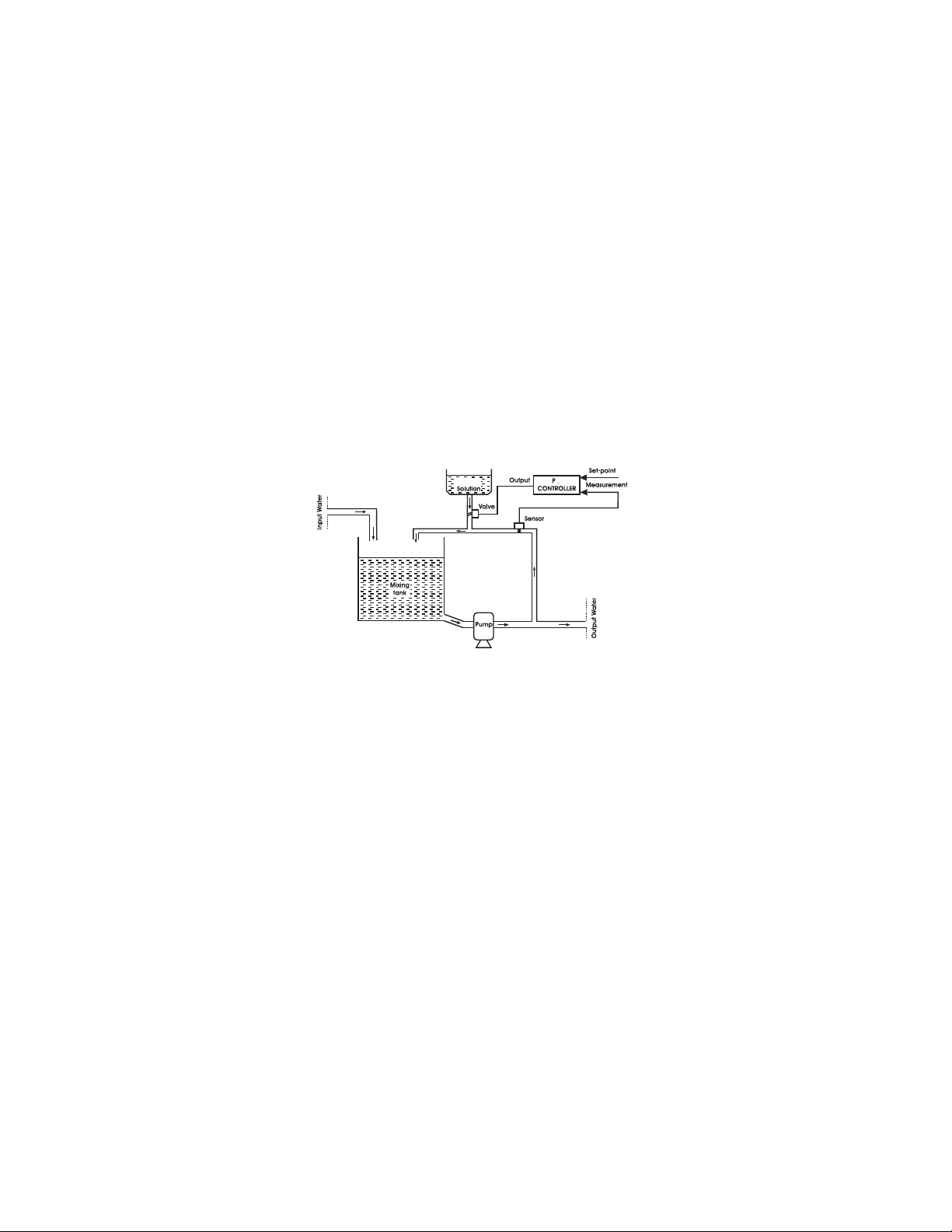
The role of this controller is to maintain a pH and EC value of the irrigation water (see diagram). The control of pH and EC is made separately.
Reagent
A simplified schematic of the process (pH and EC) is presented above.
The components are as follows:
−The mixing tank where input water and additives are combined.
−The additive solution tank containing an acid, base or fertilizer
−The valve for introducing the additive solution into the mixing tank con-
trolled by the proportional controller.
−P(proportional) Controller
−The input water source.
−The irrigation pump used to pump water from the mixing tank to the
irrigation sectors.
The Fertigation controller automatically provides a command output signal to a control element such as a pump or valve based on a sensor input
signal. The function of the proportional controller is to control the dosage
of acid/base or fertilizer in such a way that pH and EC of the process will
have the values close to specified set point. The output signal commands
the opening and closing of a valve through which the additive solution is
10
Page 11

circulated. The amount of additive solution added is relative to the opening of the valve, which is directly proportional to the magnitude of difference between the “water pool” pH and the set point.
Set point (reference value) is the desired value of the measurement.
Error is define as the difference between set point and measurement:
Error = setpoint – measurementError = setpoint – measurement
Error = setpoint – measurement
Error = setpoint – measurementError = setpoint – measurement
The descriptions and definitions of the individual control actions are as
follows:
Proportional control so called because the controller output is proportional to the magnitude of error. However, proportional control is subject
to one major limitation, steady state offset (steady deviation from the set
point). Increasing the sensitivity of the controller (controller gain) can
reduce the steady state offset but only with slow processes. Because of this
proportional control by itself is used primarily for slow, consistent processes that can tolerate high controller gain (like the control of pH and EC
in irrigation applications), which minimizes steady state offset. Both pH
and EC are controlled by using the same proportional control method.
The proportional control acts on the closing and opening timings of the
motorized valves.
The control cycle used for the pH and EC control can be set by using
panel S60 (SET PROP CTRL). To regulate the aperture of the motorized
valves the proportional control will control the opening and closing times.
These timings are in fact pecentages from the control cycle length.
The sensivity factor simply divides the times used for the actual command
of the motorized valves. It can be used for a fine time of the proportional
control. For each program and for each of the controls (pH or EC) two
parameters define the behavior of thecontroller around a designated setpoint:
- the dead band is the area around the setpoint where the dosage is “in
limits” therefore the actuators need not to change their position.
- the proportional band is the an area around the setpoint where the
proportional control takes place. Outside of these two areas the controller
will open or close the motrized valve with 80% of the control cycle.
11
Page 12
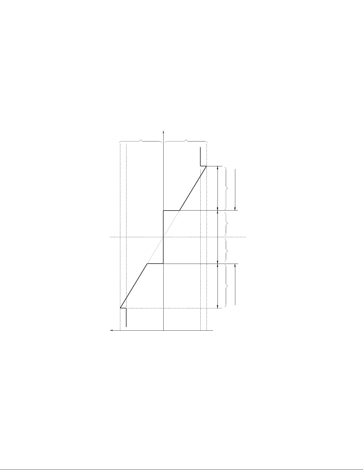
Valve
Opening
pH, EC
Max pH
Max EC
Setpoint
Valve
Opening
P Control
No Valve Control
P Control
Proportional Band
Dead Band Dead Band
Proportional Band
High Alarm Area
Low Alarm Area
Control cycle
percentage
80%
100%
0
80%
100%
12
Page 13

AGITAGIT
AA
AGIT
AGITAGIT
For HI8060:For HI8060:
For HI8060:
For HI8060:For HI8060:
The agitator output is active in the irrigation phase of a program if the fertilizer
control is enabled. This output also commands the fertilization pumps.
For HI8050:For HI8050:
For HI8050:
For HI8050:For HI8050:
During the irrigation program, the agitators can be stopped (if working time is
zero), work continuously (if pause time is zero) or intermittently (if working time
and pause is different than zero) and can start during preirrigation, before the
fertilizer tanks are used. The agitators are set using panel S45 and can be
consulted using panel C15.
FILTER CONTROLFILTER CONTROL
FILTER CONTROL
FILTER CONTROLFILTER CONTROL
Fertigation Controller has the capability to check and automatically clean
two filters controlled by two filter-cleaning programs. Each filter cleaning
program can be started by the following conditions:
1. Following one specified irrigation program. This irrigation program
2. When a “dirty filter” alarm is activated. Cleaning by this option is set
The working time for filter cleaning programs can be set using panel
(FIL(FIL
(FIL
(FIL(FIL
MANUAL FUNCTIONSMANUAL FUNCTIONS
MANUAL FUNCTIONS
MANUAL FUNCTIONSMANUAL FUNCTIONS
TOR CONTROLTOR CONTROL
A
TOR CONTROL
AA
TOR CONTROLTOR CONTROL
can be set in panel
using panel
TERS CTRL).TERS CTRL).
TERS CTRL).
TERS CTRL).TERS CTRL).
S46 S46
S46 (FILTERS CTRL).
S46 S46
S46 S46
S46 (FILTERS CTRL).
S46 S46
S45S45
S45
S45S45
The Fertigation Controller has the following Manual function capabilities:
− To switch the controller state between STOP, WORK and INIT, use panel
S49 S49
S49 (CONTROLLER STATE). The controller state can be checked using
S49 S49
C01 C01
panel
C01 (GENERAL INFO)
C01 C01
− To manually start a program use panel
− To manually stop a program use panel
− To check and to change the value for each of the outputs, use panel
S50 S50
S50 (OUTLET MAN CTRL)
S50 S50
− To erase all statistics, use panel
cates pH and conductivity averages for all irrigation programs and sectors in addition to average total irrigation accumulation. They also show
the volume of water and fertilizers on sectors, on programs and total
volumes.
− To erase the settings of one irrigation program or to erase all settings for
all irrigation programs, use panel
S65 S65
S65 (ERASE STATISTICS).
S65 S65
S47 S47
S47 (PROG MAN START)
S47 S47
S48 S48
S48 (PROG MAN STOP)
S48 S48
S66 S66
S66 (ERASE SETTINGS).
S66 S66
13
Statistics indi-
Page 14

ALARMSALARMS
ALARMS
ALARMSALARMS
Fertigation controller has the capability to supervise and generate an alarm
for the following conditions:
- Conductivity sensor out of range. Reference, minimal and maximal offset
and time-out for conductivity alarm are set using panel
TROL). The current values of conductivity sensors are displayed on panel
C06 C06
C06 (EC STATE)
C06 C06
− pH sensor out of range. Reference, minimum and maximum offset and
time-out for pH alarm are set using panel
current values of pH sensors are displayed on panel
− Problems with the water supply.
− Dirty filters.
− Low levels in fertilizer and acid tanks.
− Waste of fertilizers.
− Main irrigation counter fail.
− Overdose and underdose of fertilizer.
The system will take appropriate action and record the alarm. These actions can be:
..
.
..
S36 S36
S36 (PH CONTROL).
S36 S36
S38 S38
S38 (EC CON-
S38 S38
The
C05 C05
C05 (pH STATE)
C05 C05
• Given a pH alarm condition, the irrigation process can be set to
stop or continue using panel
S54 S54
S54 (ALARM BEHAVIOR).
S54 S54
• Given an EC alarm condition, the irrigation process can be set to
stop or continue using panel
S54 S54
S54 (ALARM BEHAVIOR).
S54 S54
• Given a dirty filter alarm condition, start the filter cleaning program
in accordance with the priority and working time settings
• Given a water supply alarm situation the controller goes in BLOCK state.
• All alarm situations are displayed on panel
All anomalies (old alarm conditions) are displayed in panel
(ANOMALY).
C23 C23
C23 (ALARM).
C23 C23
C25C25
C25
C25C25
LOGGING (DIARY) FUNCTIONS LOGGING (DIARY) FUNCTIONS
LOGGING (DIARY) FUNCTIONS
LOGGING (DIARY) FUNCTIONS LOGGING (DIARY) FUNCTIONS
− The Fertigation controller has the capability to log the most important
occurred events and values of different parameters that can offer a description of the evolution of the entire process;
− The most important values are:
- Number and time period of every program activation;
- Filter cleanings;
- Averages of pH, conductivity and temperature;
- Accumulations;
14
Page 15

- Values of sensors.
- Sectors irrigated by a program.
- Alarms;
The records of log can be searched by date. To start a search set the desired
date in panel C24 (VIEW LOG DATE). Logging records are displayed on
panel C26 (LOG).
The average value of sensors and accumulation of volumes are available
through panes C17 (TOTAL ACCUMUL) to C22 (SECTOR AVERAGES).
DADA
TE AND TIME CONTROLLER SETTINGSTE AND TIME CONTROLLER SETTINGS
DA
TE AND TIME CONTROLLER SETTINGS
DADA
TE AND TIME CONTROLLER SETTINGSTE AND TIME CONTROLLER SETTINGS
The controller date and time can be consulted on panel
INFO) and can be set using panel
PASSWORD SETUP PASSWORD SETUP
PASSWORD SETUP
PASSWORD SETUP PASSWORD SETUP
Access to Fertigation Controller can be restricted by a password. This
password can be set using panel
can be disabled using the same panel.
SERIAL COMMUNICASERIAL COMMUNICA
SERIAL COMMUNICA
SERIAL COMMUNICASERIAL COMMUNICA
The fertigation controller is able to connect with a PC and can be remotely
controlled by the PC through the Agricare program. To be able to connect
the PC must have a serial port available and a Windows operating system. The serial cable must be crossover and with male – female connector. For more details please consult the help of the Agricare program.
S28 S28
S28 (SET DATE & TIME).
S28 S28
S64 S64
S64 (SET PASSWORD). The password
S64 S64
TIONTION
TION
TIONTION
C01 C01
C01 (GENERAL
C01 C01
15
Page 16
USER INTERFACEUSER INTERFACE
USER INTERFACE
USER INTERFACEUSER INTERFACE
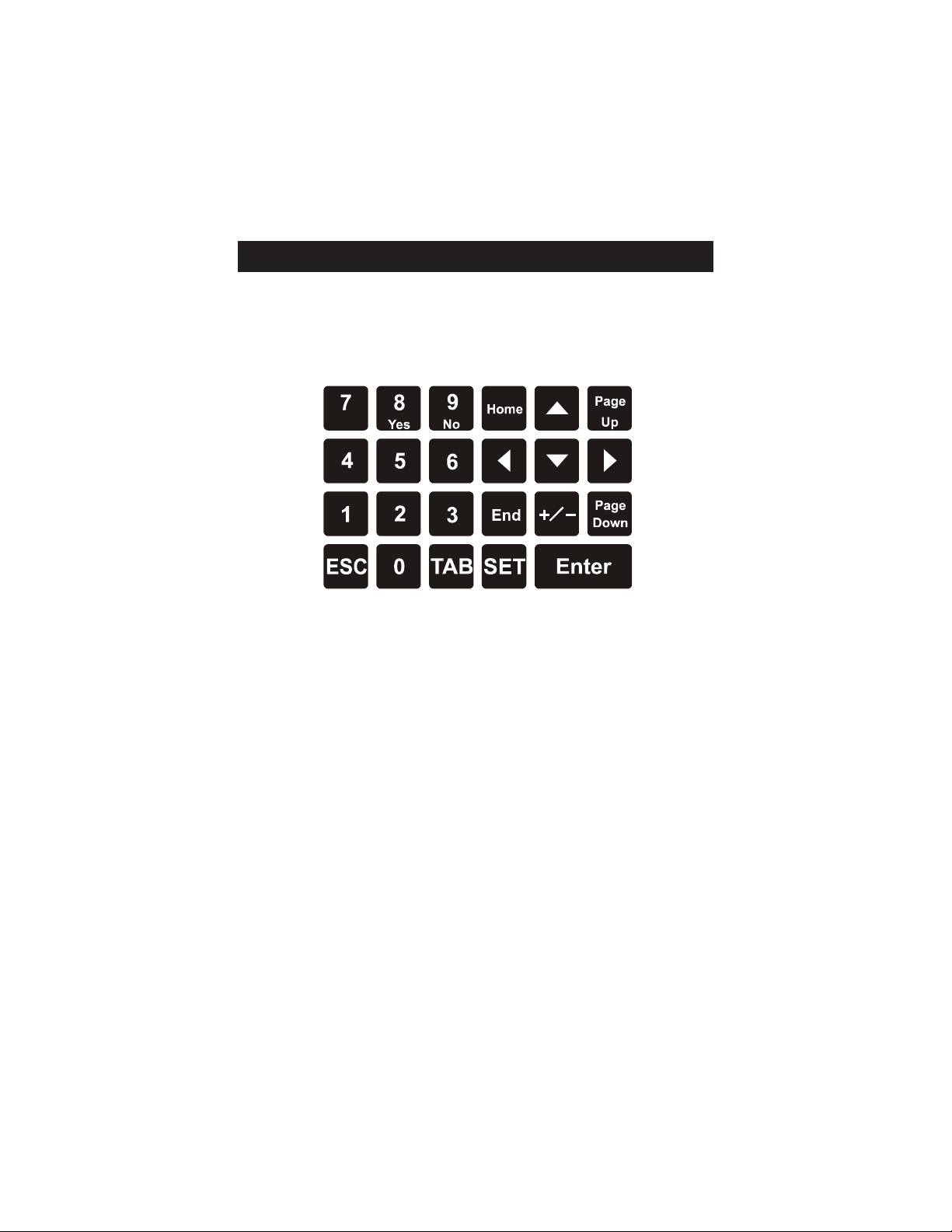
The user interface of the Fertigation Controller consists of a 4 x 20 character LCD and a 23 key keyboard (see depiction below).
KEYBOARD STRUCTUREKEYBOARD STRUCTURE
KEYBOARD STRUCTURE
KEYBOARD STRUCTUREKEYBOARD STRUCTURE
Fig. 1.1: Fig. 1.1:
Fig. 1.1: Keyboard layout.
Fig. 1.1: Fig. 1.1:
OPERAOPERA
OPERA
OPERAOPERA
The Fertigation controller operates primarily in two major modes: Consulting Mode and Setting Mode. User interface panels (screens) are broken
down into two categories:
1. CONSULTING PANELS
2. SETTING PANELS
Both modes of operation a readily available to the user.
TING MODESTING MODES
TING MODES
TING MODESTING MODES
1. CONSUL TING MODE:
The consulting mode allows the user to view the current state and set
conditions of the Fertigation Controller. While in consulting mode (
key not pressed) all 68 panels can be viewed by one of 2 browsing methods. The primary consulting screens are designated from C
2727
C
27. The following outline highlights the functions of the consulting mode.
2727
PP
− two browsing methods are enabled. See Section
METHODSMETHODS
METHODS for more details.
METHODSMETHODS
ARROWS KEYSARROWS KEYS
−
ARROWS KEYS can be used to move the cursor within a currently
ARROWS KEYSARROWS KEYS
selected panel to select specific data (only if data items are selectable) to
be viewed.
16
ANEL BROWSINGANEL BROWSING
P
ANEL BROWSING
PP
ANEL BROWSINGANEL BROWSING
0101
01 through
0101
SETSET
SET
SETSET
Page 17

ESCESC
−
ESC key can be used as a shortcut key to access the
ESCESC
STATE) panel from any currently viewed panel.
HOMEHOME
−
HOME key can be used as a shortcut key to access the
HOMEHOME
ERAL INFO) panel from any currently viewed panel.
ENDEND
−
END key can be used as a shortcut key to access the
ENDEND
STOP) panel from any currently viewed panel.
TT
ABAB
−
T
AB key can be used to switch the focus between the
TT
ABAB
objectobject
object and the
objectobject
dexed. If there is no index parameter present on the current panel, the
TT
ABAB
T
AB key has no effect. The program number indexes panels. For ex-
TT
ABAB
ample, panel
each program. Once panel
the focus (cursor) is shifted from the panel number to the program number “Prog 01”. The
each program state consecutively without leaving the panel.
ENTERENTER
−
ENTER key is used to confirm any new values entered in any of the
ENTERENTER
selected panels. This is only possible if data items on a panel (screen) are
selectable.
panels index parameterpanels index parameter
panels index parameter if the current panel is in-
panels index parameterpanels index parameter
C04 C04
C04 (PROGRAM STATE) displays the current state for
C04 C04
C04C04
C04 is selected and the
C04C04
ARROW KEYSARROW KEYS
ARROW KEYS can now be used to scroll through
ARROW KEYSARROW KEYS
C04C04
C04 (PROGRAM
C04C04
C01 C01
C01 (GEN-
C01 C01
S48 S48
S48 (PROG MAN
S48 S48
panel numberpanel number
panel number
panel numberpanel number
TT
ABAB
T
AB key pressed,
TT
ABAB
2. SETTING MODE:
The setting mode allows configuration of all adjustable parameters of the
S28S28
Fertigation controller. The setting screens are designated from
All 68 panels can be viewed by one of 2 browsing methods. The setting
mode is executed by selecting the appropriate screen and pressing the
SETSET
SET key. Once the setting mode is entered both panel-browsing methods
SETSET
are disabled and navigation is allowed only within the currently selected
panel. The following outline highlights the functions of the Setting Mode.
− Both panel (screen) browsing methods are disabled. See Section
BROWSING METHODSBROWSING METHODS
BROWSING METHODS
BROWSING METHODSBROWSING METHODS
− Focus (cursor location) is automatically shifted to the first editable data
object on the selected panel.
UPUP
, DOWN, DOWN
−
UP
, DOWN
UPUP
, DOWN, DOWN
objects within the current panel.
LEFTLEFT
, RIGHT arrow keys, RIGHT arrow keys
−
LEFT
, RIGHT arrow keys allow navigation within the currently fo-
LEFTLEFT
, RIGHT arrow keys, RIGHT arrow keys
cused
object then the focus is transferred to the previous or next editable item
within the current panel.
TT
ABAB
−
T
AB key can be used to move only in a forward direction, from one data
TT
ABAB
object to the next within the selected panel.
ENTERENTER
−
ENTER key confirms all data entered in a current panel. Once the
ENTERENTER
arrow keysarrow keys
arrow keys allows navigation between all editable data
arrow keysarrow keys
data object.data object.
data object. If the cursor exceeds the boundaries of the data
data object.data object.
S28 to
S28S28
S68S68
S68.
S68S68
PP
ANELANEL
P
ANEL
PP
ANELANEL
17
Page 18

ENTERENTER
ENTER key is pressed and data confirmed, the controller reverts to con-
ENTERENTER
sulting mode. The
ESCESC
−
ESC key cancels new data entered in the currently focused data object
ESCESC
and exits the setting mode. The change of data is not saved in the current
object and the previous setting is maintained.
NONO
TETE
NO
TE: Data that has been changed in an editable data object is saved
NONO
TETE
once focus has been removed from that object by pressing the
KEYSKEYS
KEYS or
KEYSKEYS
PP
ANELS BROWSING METHODSANELS BROWSING METHODS
P
ANELS BROWSING METHODS
PP
ANELS BROWSING METHODSANELS BROWSING METHODS
In consulting mode, 2 browsing methods are available to view each of the
68 panels (screens) of the Fertigation controller.
−
keys allows consecutive navigation from one panel to the next. Direction
is dependent upon which key is selected.
−
entered directly using the panel number located on the bottom right corner of every panel, prefixed by a
initially focused object on each screen. After entering the value by using
the key pad and
panel.
NONO
NO
NONO
setting mode, both browsing methods are disabled.
TT
ABAB
T
AB.
TT
ABAB
StepStep
-by-by
--
Step
StepStep
Direct access browsingDirect access browsing
Direct access browsing: the number of the desired panel can be
Direct access browsingDirect access browsing
TETE
TE
TETE
step browsingstep browsing
-by
-
step browsing: pressing
-by-by
--
step browsingstep browsing
: :
: If a panel is selected and the
: :
SETSET
SET key must be pressed to re-enter setting mode.
SETSET
ARROWARROW
ARROW
ARROWARROW
PP
AA
CC
C or
CC
arrow keysarrow keys
arrow keys, press the
arrow keysarrow keys
GE UPGE UP
P
A
GE UP and
PP
AA
GE UPGE UP
SS
S. The panel number object is the
SS
ENTERENTER
ENTER key to view the selected
ENTERENTER
SETSET
SET key is pressed, entering the
SETSET
PP
AA
GE DOWNGE DOWN
P
A
GE DOWN
PP
AA
GE DOWNGE DOWN
18
Page 19
PP
ANEL LISTANEL LIST
P
ANEL LIST
PP
ANEL LISTANEL LIST
REBMUNYBELBATLENAPREBMUNYBELBATLENAP
REBMUNYBELBATLENAPREBMUNYBELBATLENAP
REBMUNYBELBATLENAP
NOCSLENAPGNITLUSNOC
10OFNILARENEGNOITAMR82EMIT&ETADTES
20ETATSEMULOV92ELBATEMITEVITCA
30ETATSSROSNES03YADKR
40ETATSMARGORP13YTIROIRPTES
50ETATSHp23SNOITIDNOCTRATS
60ETATSCE33EMITTRATSTES
70SNOITIDNOCEMITKROW43STAEPERMARGOR
80STCILFNOC&YTIROIRP53NOITAGIRRITSOP/ERP
90ETATSNOITAGIRRI63LORTNOCHp
01ROTCAFNOITCERROCLAUNAM73EDOMLORTNOCREZI
11NOITCERROCLATOT83LORTNOCCE
21SNOITCERROCCE93SREZILITREFTES
31ETATSSROTCES04
41ETATSREZILITREF14
51ETATSROTATIGA24LORTNOCREZILITREFEMULOV
SLENAPGNITLUS
SLENAPGNITLUSNOCSLENAPGNITLUSNOCSLENAPGNITTESSLENAPGNITTES
SLENAPGNITLUSNOC
OW
P
S
LITREF
GIFNOC
LORTNOC
SLENAPGNITTESSLENAPGNITTES
SLENAPGNITTE
LORTNOCLAITNEREFFIDCE
NOITARU
REZILITREFCIRTEMOITAR
GORP34SROTCESTES
61TRATSTSALMAR
71NOITALUMUCCALATOT44NOITCERROCNOITAGIRRI
81NOITALUMUCCAMARGORP54SROTATIGATES
ES64LORTNOCSRETLIF
91NOITALUMUCCAROTC
02SEGAREVALATOT74TRATSLAUNAMMARGORP
12SEGAREVAMARGORP84POTSLAUNAMMARGORP
22SEGAREVAROTCES94ETATS
32MRALA05LORTNOCLAUNAMSTELTUO
42ETADGOLWEIV15SNOITPOLORTNOCHp
RELLORTNOC
19
Page 20

REBMUNYBELBATLENAPREBMUNYBELBATLENAP
REBMUNYBELBATLENAPREBMUNYBELBATLENAP
REBMUNYBELBATLENAP
NOCSLENAPGNITLUSNOC
52SEILAMONA25SMRALAGNISODEMULOV
62GOL35SMRALAEMULOVNOPOTS
72ECITCARPYROTAROBALDOOG45RO
SLENAPGNITLUS
SLENAPGNITLUSNOCSLENAPGNITLUSNOCSLENAPGNITTESSLENAPGNITTES
SLENAPGNITLUSNOC
55EDOMLORTNOCNOITAGIRRI
65SRETEMARAPWOLFTES
75SGNITTESRETNUOC
85NOITCELESSPMUP
95SEVLAVDEZIROTOM
06LR
16SGNIMITTES
26LORTNOCELBANE
36TESSROSNESGNGIGOL
46DROWSSAPTES
56SCITSITATSESARE
66SGNITTESESARE
76SROSNE
S
IVAHEBMRALA
TCPORPTES
SETARBILAC
SLENAPGNITTESSLENAPGNITTES
SLENAPGNITTE
20
86NOITACIFITNEDIRELLORTNOC
Page 21
GLARENE)RELLORTNOC(
NOITCNUFYBELBATLENAPNOITCNUFYBELBATLENAP
NOITCNUFYBELBATLENAPNOITCNUFYBELBATLENAP
NOITCNUFYBELBATLENAP
LENAPLENAP
LENAPLENAP
TCNUFLENAPNOITCNUFLENAP
NOITCNUFLENAPNOITCNUFLENAP
NOI
NOITCNUFLENAP
GNITLUSNOC
GNITLUSNOCMARGORP20ETATSEMULOV
LENAP
REBMUNREBMUN
R
EBMUNREBMUN
REBMUN
10NOITAMROFNILARENEG
30E
72ECITCARPYROTAROBALDOOG
40ETATSMARGORP
50ETATSHp
60ETATSCE
TATSSROSNES
EMANLENAPEMANLENAP
EMANLENAPEMANLENAP
EMANLENAP
70SNOITIDNO
80STCILFNOCDNAYTIROIRP
90ETATSNOITAGIRRI
01
11NOITCERROCLATOT
21SNOITCERROCCE
1ETATSSROSNES
3
41ETATSREZILITREF
51ETATSROTATIGA
61TRATSTSALMARGORP
GNITLUSNOCSCITSITATS71NOITALUMUCCALATOT
81NOIT
91NOITALUMUCCAROTCES
02SEGAREVALATOT
12SEGAREVAMARGORP
22SEGAREVAROTCES
32MRALA
CEMITKROW
NOITCERROCLAUNAM
ROTCAF
ALUMUCCAMARGORP
42ETADGOLWEIV
21
Page 22
NOITCNUFYBELBATLENAPNOITCNUFYBELBATLENAP
NOITCNUFYBELBATLENAPNOITCNUFYBELBATLENAP
NOITCNUFYBELBATLENAP
LENAPLENAP
LENAPLENAP
TCNUFLENAPNOITCNUFLENAP
NOITCNUFLENAPNOITCNUFLENAP
NOI
NOITCNUFLENAP
)RELLORTNOC(LARENEG
SGNITTES
LENAP
REBMUNREBMUN
REBMUNREBMUN
REBMUN
52SEILAMONA
62GOL
82EMIT&E
73EDOMLORTNOCREZILITREF
64LORTNOCSRETLIF
15SNOITPOLORTNOCHp
25SMRALAGNISODEMULOV
35SMRALAEMULOVNOPOTS
TADTES
EMANLENAPEMANLENAP
EMANLENAPEMANLENAP
EMANLENAP
45RO
65SRETEMARAPWOLFTES
75SGNITTESRETNUOC
95SEVLAVDEZIROTOM
06LRTCPOPPTES
16SGNIMITTES
26LORTNOCELBANE
36TE
46DROWSSAPTES
76SROSNESETARBILAC
86NOITACIFITNEDIRELLORTNOC
SGNITTESMARGORP92ELBATEMITEVITCA
03Y
13YTIROIRPTES
23SNOITIDNOCTRATS
33EMITTRATSTES
43STAEPERMARGORP
IVAHEBMRALA
SSROSNESGNIGGOL
ADKROW
22
Page 23
NOITCNUFYBELBATLENAPNOITCNUFYBELBATLENAP
NOITCNUFYBELBATLENAPNOITCNUFYBELBATLENAP
NOITCNUFYBELBATLENAP
LENAPLENAP
LENAPLENAP
TCNUFLENAPNOITCNUFLENAP
NOITCNUFLENAPNOITCNUFLENAP
NOI
NOITCNUFLENAP
LENAP
REBMUNREBMUN
R
EBMUNREBMUN
REBMUN
53NOITAGIRRITSOP/ERP
63HpLORTNOC
83LORTNOCCE
EMANLENAPEMANLENAP
EMANLENAPEMANLENAP
EMANLENAP
93SREZILITR
04
14
24LORTNOCREZILITREFEMULOV
34SROTC
44NOITCERROCNOITAGIRRI
54SROTATIGATES
55EDOMLORTNOCNOITAGIRRI
85NOITCELESSPMUP
SNOITCNUFLAUNAM74TRATSLAUNA
84POTSLAUNAMMARGORP
94ETATSRELLORTNOC
05LORTNOCLAUNAMSTELTUO
56SCITSITATSESARE
66SGNITTESESARE
EFTES
LORTNOC
ESTES
MMARGORP
LORTNOCLAITNEREFFIDCE
NOITARUGIFNOC
REZILITREFCIRTEMOITAR
23
Page 24

PANEL DESCRIPTIONSPANEL DESCRIPTIONS
PANEL DESCRIPTIONS
PANEL DESCRIPTIONSPANEL DESCRIPTIONS
Below are described all the panels in the controllers. The panels are divided in
three sections: Initialization panels, consulting panels and setting panels. The
data fields within each panel are described from left to right unless otherwise
specified.
INITIALIZAINITIALIZA
INITIALIZA
INITIALIZAINITIALIZA
INITIALIZATION PANEL
This panel is shown during Fertigation Controller INITIALIZATION state and
contains the HANNA INSTRUMENTS logo and the name of the controller.
The last line is used to display the current status of the initialization sequence.
This panel is also used to display any possible errors that may occur during
the start up sequence.
START PANEL
This panel is displayed after successful initialization or whenever the password
authentication sequence fails (user will be logged off due to incorrect password entry). This panel displays the date and time and the bottom left corner
it is shown the Fertigation Controller functional state.
It is important to note that the Fertigation Controller is normallyIt is important to note that the Fertigation Controller is normally
It is important to note that the Fertigation Controller is normally
It is important to note that the Fertigation Controller is normallyIt is important to note that the Fertigation Controller is normally
functioning at this point if the required external conditions arefunctioning at this point if the required external conditions are
functioning at this point if the required external conditions are
functioning at this point if the required external conditions arefunctioning at this point if the required external conditions are
met even if the user is logged off.met even if the user is logged off.
met even if the user is logged off. At this stage, when the user presses
met even if the user is logged off.met even if the user is logged off.
ENTERENTER
the
ENTER key another login opportunity will be given if the password au-
ENTERENTER
thentication process is enabled. This feature can be specified via panel
(SET PASSWORD).
TION PTION P
TION P
TION PTION P
HANNA INSTRUMENTS
HI8050 V00.01-004E
INITIALIZATION:
Loading StringTable
HANNA INSTRUMENTS
HI8050 CONTROLLER
Fri 15-03-2000 13:15
STOP PRESS ENTER
ANELSANELS
ANELS
ANELSANELS
S64S64
S64
S64S64
24
Page 25

INPUT PASSWORD PANEL
Enter password:
****
This panel is displayed during the password authentication sequence. If this
STST
ARAR
sequence fails the user will be logged off and the
played. If the password is correct panel
The default password is
00000000
0000. See section Setting Password for instructions
00000000
C01C01
C01 (GENERAL INFO) is displayed.
C01C01
TT
ST
AR
T panel will be dis-
STST
ARAR
TT
on setting this feature.
Although access to the controllers features are denied the functionality of the
controller is not directly affected if a password authentication sequence fails.
CONSUL CONSUL
CONSUL
CONSUL CONSUL
TING PTING P
TING P
TING PTING P
ANELSANELS
ANELS
ANELSANELS
GENERAL INFO – C01
WORK Anomalies 00
Prog 08 06.4pH
Sect 07 02.1mS 13:15
GENERAL INFO C01
This panel displays the following information from top left:
Fertigation Controller Functional State (top left corner) Fertigation Controller Functional State (top left corner)
−
Fertigation Controller Functional State (top left corner) - When
Fertigation Controller Functional State (top left corner) Fertigation Controller Functional State (top left corner)
WORKWORK
WORKWORK
INITIAL-INITIAL-
INITIAL-
INITIAL-INITIAL-
the controller is running it can be in one of the following states:
IZAIZA
TIONTION
, ST, ST
OPOP
IZA
IZAIZA
TION
TIONTION
, ST
, ST, ST
, WORK, WORK
OP
, WORK
OPOP
, WORK, WORK
first powered on the first state is
performs internal tests. In
normal conditions the functional state is
, BL, BL
OCKOCK
, BL
, BL, BL
STST
ST
STST
..
OCK
. When the Fertigation Controller is
OCKOCK
..
INITIALIZAINITIALIZA
INITIALIZA
INITIALIZAINITIALIZA
OPOP
OP state all programs are suspended. Under
OPOP
TIONTION
TION. In this state the unit
TIONTION
WORKWORK
WORK. In the
WORKWORK
WORK state all
irrigation and fertilization programs are executed. If an alarm occurs the
Fertigation Controller enters the
BLOCKBLOCK
BLOCK state until the alarm condition is
BLOCKBLOCK
corrected. The user can customize the alarm management system behavior using setting panels
S54S54
S54 (ALARM BEHAVIOR).
S54S54
Anomalies (top right corner) - Anomalies (top right corner) -
−
Anomalies (top right corner) - The anomalies counter represents the
Anomalies (top right corner) - Anomalies (top right corner) -
S36, S38S36, S38
S36, S38 (pH and EC CONTROL) and panel
S36, S38S36, S38
number of alarms triggered since the last reset of the counter. This counter
can be customized and cleared along with all system statistics via setting
panel S65 (ERASE STATISTICS).
25
Page 26

Program NumberProgram Number
−
Program Number - The active program is displayed. If no program is
Program NumberProgram Number
active this field is not visible.
pH sensor readingpH sensor reading
−
pH sensor reading - The reading of pH sensor.
pH sensor readingpH sensor reading
Sector NumbersSector Numbers
−
Sector Numbers - All sectors assigned to the active program are dis-
Sector NumbersSector Numbers
played (cyclically) and only when an active program is running. If no
program is active no number is visible.
EC sensor reading - EC sensor reading -
−
EC sensor reading - The reading of EC sensor.
EC sensor reading - EC sensor reading -
System clock.System clock.
−
System clock.
System clock.System clock.
If an alarm condition is present the time indication will also flash “ALARM”
to alert the user.
NONO
TETE
::
NO
TE
: If the user is logged in and the operational mode is
NONO
TETE
::
MODEMODE
MODE, this panel can be accessed anytime and from any panel using the
MODEMODE
HOMEHOME
HOME key as a shortcut.
HOMEHOME
NONO
TETE
::
NO
TE
: The Clock, pH and EC sensors are always visible regardless of state.
NONO
TETE
::
CONSULCONSUL
CONSUL
CONSULCONSUL
TINGTING
TING
TINGTING
VOLUME STATE - C02
Irr:0114320L Prog:01
F1:00050L F2:00500L
F3:00370L F4:00000L
VOLUME STATE C02
The purpose of this panel is to allow the user to inspect the volumes of irrigation water and fertilizers that have been dosed since the current program was
launched in execution. If the current program is not READY, ACTIVE or WAIT
in the place of volume values will be nothing. This panel contains the following information:
Program NumberProgram Number
−
Program Number - the current program (the one for which the volume
Program NumberProgram Number
values are).
Irrigation volume Irrigation volume
−
Irrigation volume – the volume of irrigation water.
Irrigation volume Irrigation volume
Fertilizer n volumeFertilizer n volume
−
Fertilizer n volume – the volume of fertilizer from tank n.
Fertilizer n volumeFertilizer n volume
SENSORS STATE – C03
Active Program: 04
06.3pH +22C
06.4mS 13:15
SENSORS STATE C03
This panel provides an overview of the real time values of the system sensors.
26
Page 27

This panel contains the following information:
Active program number Active program number
−
Active program number - displays the number of the executing pro-
Active program number Active program number
gram. If no program is running no number is displayed.
− −
pH sensor readingpH sensor reading
−
pH sensor reading
− −
pH sensor readingpH sensor reading
− −
TT
emperature sensor readingemperature sensor reading
−
T
emperature sensor reading
− −
TT
emperature sensor readingemperature sensor reading
− −
EC sensor readingEC sensor reading
−
EC sensor reading
− −
EC sensor readingEC sensor reading
− −
System clock.System clock.
−
System clock.
− −
System clock.System clock.
PROGRAM STATE – C04
Prog 08 Active
Started by Time Cond
Repeat 02/05 13:15
PROGRAM STATE C04
The purpose of this panel is to allow the user to inspect the status and settings
of a particular program. The program number indexes this panel. This panel
contains the following information:
Program NumberProgram Number
−
Program Number – The current selected program. Act as index for the
Program NumberProgram Number
panel (used to view settings for all programs).
NOTE: This is the only panel where the current program can be changed.
Program StateProgram State
−
Program State - During the lifetime of a program it cycles through several
Program StateProgram State
states. Each program is initially in NO SET state which means no settings
have been applied to the program by the user. Once the settings have
been applied the program is considered in SET state. Once a specific
condition such as start time is met the program passes to READY state to
await execution. Once the program reaches the highest priority and the
start time is met, the program passes to ACTIVE state and executes. The
program may be suspended and placed in WAIT state due to a higher
priority program moving to ACTIVE state or a specific alarm condition
triggering. When a program completes execution it is placed in FINISHED state. The cycle may be repeated and the program returned to
ready state if the program repeats were specified after a set delay period.
Program Started by Program Started by
−
Program Started by - Displays how the last program start was triggered.
Program Started by Program Started by
Programs can be started by a met time condition, manual start, low level
in external tank, or directly after the completion of another program. If the
program is in NO SET (no settings applied to program) or in SET (settings
applied but conditions not met) state, .Started by field is blank.
RepeatRepeat
−
Repeat - Displays the current repetition followed by (/) the maximum num-
RepeatRepeat
ber of the programmed repetitions.
27
Page 28

− −
System clockSystem clock
−
System clock
− −
System clockSystem clock
REMINDER: In CONSULTING MODE the ESC key can be used as a
shortcut key to access this panel from any panel.
PH STATE – C05
Prog 08 Ref=06.4pH
pHout:06.4pH 13:15
PH STATE C05
The purpose of this panel is to allow the user to inspect the current pH reference point for a specific program and the real time pH sensor readings. The
program number indexes this panel. This panel contains the following information:
Program NumberProgram Number
−
Program Number – The current selected program. Act as index for the
Program NumberProgram Number
panel (used to view settings for all programs).
RefRef
−
Ref = Reference or set point pH value for the specified program.
RefRef
PhoutPhout
−
Phout - Real time value of pH sensor. This reading applies to the entire
PhoutPhout
process and is not program specific.
− −
System clockSystem clock
−
System clock
− −
System clockSystem clock
EC STATE – C06
Prog 08 Ref=05.6mS
ECin :01.1mS
Count:02.0mS 13:15
EC STATE C06
The purpose of this panel is to allow the user to inspect the current EC reference point for a specific program and the real time EC sensor readings. The
program number indexes this panel. This panel contains the following information:
PP
rogram Numberrogram Number
−
P
rogram Number - Panel index (used to view settings for all programs).
PP
rogram Numberrogram Number
RefRef
−
Ref - Reference or set point EC value for the specified program.
RefRef
EcoutEcout
−
Ecout - Real time value of EC sensor. This reading applies to the entire
EcoutEcout
process and is not program specific.
− EC in - Real time value of EC input sensor. This sensor measure the conductivity of the incoming water supply. This reading applies to the entire
process and is not program specific.
− System clock
28
Page 29

WORK TIME COND – C07
Prog 08 Time Y
Day Y
Period Y 13:15
WORK TIME COND C07
The program number indexes this panel. This panel contains the following
information:
PP
rogram Numberrogram Number
−
P
rogram Number - Panel index (used to view settings for all programs).
PP
rogram Numberrogram Number
− Time - Indicates if the selected program’s daily schedule is met at the actual
moment
− Day - Indicates if the selected program’s monthly schedule is met at the
actual moment
− Period - Indicates if the selected program’s yearly schedule is met at the
actual moment
− System clock
PRIOR&CONFLICTS – C08
Prog 08 Priority 06
Conflict Programs 09
13:15
PRIOR&CONFLICTS C08
This panel indicates the priority level of the indexed program. Priority settings
play a roll in program execution when two or more programs have similar
starting conditions. The priority for a given program can be set using panel
S31S31
S31 (SET PRIORITY). The Conflict Programs counter cyclically displays all
S31S31
programs that are in conflict with the currently active program. Programs can
be in conflict if their specific start and running conditions are synchronous.
Given this scenario, the program having the highest priority will become active.
The program number indexes this panel. This panel contains the following
information:
PP
rogram Numberrogram Number
−
P
rogram Number - Panel index (used to view settings for all programs).
PP
rogram Numberrogram Number
PriorityPriority
−
Priority - Displays priority of indexed program
PriorityPriority
Conflict ProgramsConflict Programs
−
Conflict Programs - Cyclically displays the program number of programs
Conflict ProgramsConflict Programs
in conflict with the currently active program.
System clockSystem clock
−
System clock.
System clockSystem clock
29
Page 30

IRRIG STATE – C09
Prog 08 IRRIG
Set 01:15:20+005:55
Done 00:45:10 13:15
IRRIG STATE C09
This panel displays the current irrigation state of the indexed program. Time or
volume can control irrigation and the above panel displays the set value and
the amount of irrigation currently completed. The mode of irrigation (time or
volume) can be selected using panel
S55S55
S55 (IRRIG CTRL MODE). The program
S55S55
number indexes this panel. This panel contains the following information:
PP
rogram Numberrogram Number
−
P
rogram Number - Panel index (used to view settings for all programs).
PP
rogram Numberrogram Number
IrrigIrrig
−
Irrig - the state of the program
IrrigIrrig
: :
: Irrig - irrigating; Preirrig - preirrigating;
: :
Postirrig - postirrigation; Idle - irrigating or waiting for irrigation
Set - Set -
−
Set - Displays the required (set) value of irrigation in time or volume.
Set - Set -
Irrigation correction value Irrigation correction value
−
Irrigation correction value (number directly following Set value)
Irrigation correction value Irrigation correction value
DoneDone
−
Done - Displays the value already done of irrigation time or volume.
DoneDone
System clockSystem clock
−
System clock
System clockSystem clock
MAN CORRECTION – C10
Prog 08
+015%
+00:15:55 13:15
MAN CORRECTION C10
This panel displays how much the programmed irrigation parameters are
manually modified (corrected). The program number indexes this panel. This
panel contains the following information:
PP
rogram Numberrogram Number
−
P
rogram Number - Panel index (used to view settings for all programs).
PP
rogram Numberrogram Number
Irrigation extension percentageIrrigation extension percentage
−
Irrigation extension percentage - Displays the overall extension per-
Irrigation extension percentageIrrigation extension percentage
centage of irrigation for the selected program due to manual correction.
Irrigation extension value Irrigation extension value
−
Irrigation extension value - Displays (in time or volume) the extension
Irrigation extension value Irrigation extension value
value of irrigation for the selected program due to manual correction.
System clockSystem clock
−
System clock
System clockSystem clock
TOTAL CORRECTION – C11
Prog 08
+035%
+02:00:13 13:15
TOTAL CORRECTION C11
30
Page 31

This panel displays how much the programmed irrigation parameters are
modified due to both manual and temperature corrections. The program number
indexes this panel. This panel contains the following information:
PP
rogram Numberrogram Number
−
P
rogram Number - Panel index (used to view settings for all programs).
PP
rogram Numberrogram Number
Irrigation extension percentageIrrigation extension percentage
−
Irrigation extension percentage - Displays the overall extension per-
Irrigation extension percentageIrrigation extension percentage
centage for a selected program.
Irrigation extension valueIrrigation extension value
−
Irrigation extension value - Displays (time or volume) the total extension
Irrigation extension valueIrrigation extension value
value of irrigation for the selected program.
System clockSystem clock
−
System clock
System clockSystem clock
EC CORRECTION - C12
Prog 08 Ref=02.1mS
TCorr:-00.3mS
Input:+01.2mS 13:15
EC CORRECTIONS C12
This panel shows the correction of EC with temperature and with the EC of the
input water. The program number indexes this panel. This panel contains the
following information:
PP
rogram Numberrogram Number
−
P
rogram Number - Panel index (used to view settings for all programs).
PP
rogram Numberrogram Number
TT
emperature correctionemperature correction
−
T
emperature correction - Displays the amount with which the reference is
TT
emperature correctionemperature correction
decreased because of temperature rise.
Input EC correctionInput EC correction
−
Input EC correction - Displays the amount of which the EC reference is
Input EC correctionInput EC correction
corrected due to a deviation of the EC of the input water adverse to the
EC input setpoint.
System clockSystem clock
−
System clock
System clockSystem clock
SECTOR STATE – C13
Prog 08 Sect 33/21
Set 00:10:30+009:45
Done 00:03:10 13:15
SECTOR STATE C13
This panel displays the state of each sector. Each sector has an electro-valve
assigned. When a particular sector requires irrigation its corresponding electrovalve is opened for a specified period of time. Sector label along with valve
number (upper right corner of display) indexes this panel. This panel contains
the following information:
- Program Number - Program Number
- Program Number - Reflects the selected program (can be selected only
- Program Number - Program Number
inside panel C 04).
- Sect - Sect
- Sect - The first number displayed is the sector number followed by ‘/’ the
- Sect - Sect
31
Page 32

valve number assigned to that sector. This parameter indexes the sectors
for this panel.
SetSet
−
Set - Displays the amount of irrigation water set in time or volume for the
SetSet
selected sector/valve of the indicated program.
Irrigation correction value Irrigation correction value
−
Irrigation correction value (number directly following Set value) - Dis-
Irrigation correction value Irrigation correction value
plays correction value in time or volume for the selected sector/valve of
the indicated program.
DoneDone
−
Done - Displays the current point of irrigation in time or volume
DoneDone
for the
selected sector/valve of the indicated program.
− −
System clockSystem clock
−
System clock
− −
System clockSystem clock
NONO
TETE
::
NO
TE
: The label of sector consists of a numeric “tag” for the assigned valve.
NONO
TETE
::
Sector labels can be specified using panel
S43 S43
S43 (SET SECTORS). As default the
S43 S43
sector label will be identical to the corresponding valve number.
FERTILIZ STATE – C14
Prog 02 Fert 02
Set 40%
Current 20% 13:15
FERTILIZ STATE C14
This panel displays the set and current amount of fertilizer used for a specific
program. The Fertigation Controller controls the dosing of 4 fertilizers. In this
panel the fertilizer number is used as the index, allowing inspection of the
percent values for one up to four fertilizer tanks involved in the selected irrigation program. This panel contains the following information:
- Program Number- Program Number
- Program Number
- Program Number- Program Number
- F- F
ertert
- F
ert - Panel index. Fertilizer tank number. Each program can control 1 to 4
- F- F
ertert
fertilizer tanks.
- Set- Set
- Set - The set percentage of one of four selected fertilizers to be dosed.
- Set- Set
- Current- Current
- Current - The current dosage percentage of one of selected fertilizer, if the
- Current- Current
fertilizer control mode is EC. If the fertilizer control is ratiometric or volume, then it will display “- -”.
- System clock.- System clock.
- System clock.
- System clock.- System clock.
NONO
TETE
: :
NO
TE
: The fertilizers percentage values can be specified using the
NONO
TETE
: :
FERTILIZERS).
AGITATOR STATE – C15 (only for HI8050)
Prog 08
WORK 00:03 WORK
PAUSE 00:02 13:15
AGITATOR STATE C15
32
S39S39
S39 (SET
S39S39
Page 33

This panel displays the state of the agitator for the current selected program.
The agitators can be activated before dosing of a fertilizer, during dosing, or
intermittently throughout the program. The program number indexes this panel.
This panel contains the following information:
PP
rogram Numberrogram Number
−
P
rogram Number - Panel index (used to view settings for all programs).
PP
rogram Numberrogram Number
WW
orkork
−
W
ork – the set working time for the agitator.
WW
orkork
PP
auseause
−
P
ause – the set pause time for the agitator.
PP
auseause
− −
System clock.System clock.
−
System clock.
− −
System clock.System clock.
NONO
TETE
::
NO
TE
: For HI8060 the agitators are wired to the fertilizer pump control signal.
NONO
TETE
::
PROG LAST START – C16
Prog 08 Filter -Last start Manual
At 28-08 18:32 13:15
PROG LAST START C16
This panel displays the starting reason and the time moment of the indexed
program’s previous start, including filter-cleaning programs. There are 2 filter-cleaning programs one for each filter. The filter programs follow the indexed irrigation programs. For example, if the Fertigation Controller is equipped
with 10 irrigation programs, “Prog” number 11 and 12 will be designated for
the two filter cleaning programs on the above panel. In this case the first 10
program numbers will indicate the last start data for the irrigation process and
programs 11 and 12 will indicate the last start data for filter cleaning. The
program number indexes this panel. This panel contains the following information:
PP
rogram Numberrogram Number
−
P
rogram Number - Panel index (used to view settings for all programs).
PP
rogram Numberrogram Number
FilterFilter
−
Filter - Filter number
FilterFilter
Last StartLast Start
−
Last Start - The previous start trigger for the indexed program (irrigation or
Last StartLast Start
filter cleaning).
AtAt
−
At - The date and time moment of the previous start for the indexed pro-
AtAt
gram.
− −
System clock.System clock.
−
System clock.
− −
System clock.System clock.
TOTAL ACCUMUL – C17
From: 09-26 13:37:12
0007654L Irrig
13:15
TOTAL ACCUMUL C17
This panel provides a total (in time or volume) of the entire irrigation process
33
Page 34

(all programs) from the reset time. All Fertigation Controller’s statistics including accumulations can be erased (manually, daily at specified hour, on overflow ) within panel S 65 (ERASE STATISTICS).
This panel contains the following information:
--
FF
romrom
-
F
rom - Time stamp indicating the beginning of the overall irrigation process.
--
FF
romrom
--
AccumulationAccumulation
-
Accumulation - Total accumulation in time or volume
--
AccumulationAccumulation
--
Accumulation labelAccumulation label
-
Accumulation label - Accumulation label can be changed by using
--
Accumulation labelAccumulation label
the up and down arrows. This label indicates the type of accumulation
showed in this panel. This setting will also indicate the type of accumulation for panels 18 and 19.
Labels can be:
- Irrig - will show total water accumulation or total irrigation time
- Fert1 - fertilizer 1 total volume accumulation
- Fert2 - fertilizer 2 total volume accumulation
- Fert3 - fertilizer 3 total volume accumulation
- Fert4 - fertilizer 4 total volume accumulation
- Acid - acid/alkaline total volume accumulation
--
System clockSystem clock
-
System clock
--
System clockSystem clock
PROGRAM ACCUMUL – C18
From: 09-26 13:37:12
0007654L Prog 01
Activations 03 13:15
PROGRAM ACCUMUL C18
This panel provides a total (in time or volume) for each of the irrigation programs. The program number indexes this panel. This panel contains the following information:
FF
romrom
−
F
rom - Time stamp indicating the start of recording (statistics)
FF
romrom
AccumulationAccumulation
−
Accumulation - Total accumulation in time or volume for the indexed
AccumulationAccumulation
program
PP
rogram Numberrogram Number
−
P
rogram Number - Panel index (used to view settings for all programs).
PP
rogram Numberrogram Number
ActivationsActivations
−
Activations - The number of activations of the indexed program since the
ActivationsActivations
start of recording.
− −
System clock.System clock.
−
System clock.
− −
System clock.System clock.
SECTOR ACCUMUL – C19
From: 09-26 13:37:12
0123456L Sect 01/01
13:15
SECTOR ACCUMUL C19
34
Page 35

This panel provides a total (in time or volume) for each of the irrigation sectors. The valve number indexes this panel. This panel contains the following
information:
FF
romrom
−
F
rom - Time stamp indicating the start of recording (statistics)
FF
romrom
Accumulation -Accumulation -
−
Accumulation - Total accumulation in time or volume for the indexed
Accumulation -Accumulation -
valve and type of accumulation selected on panel C17 (TOTAL
ACCUMUL).
SectSect
−
Sect - The sector number (label) / valve number (index for this panel).
SectSect
− −
System clock.System clock.
−
System clock.
− −
System clock.System clock.
TOTAL AVERAGES – C20
From: 09-26 13:37:12
05.3pH
02.1mS +21C 13:15
TOTAL AVERAGES C20
This panel indicates the overall average of pH, conductivity and temperature
for the entire irrigation process. This panel contains the following information:
FF
romrom
−
F
rom - Time stamp indicating the start of recording (statistics)
FF
romrom
pHpH
−
pH - The pH total average
pHpH
mSmS
−
mS - The EC total average
mSmS
CC
−
C – The temperature total average
CC
− −
System clock.System clock.
−
System clock.
− −
System clock.System clock.
PROGRAM AVERAGES – C21
From: 09-26 13:37:12
05.3pH Prog 01
02.1mS +21C 13:15
PROGRAM AVERAGES C21
This panel provides a pH, EC and temperature average for each of the irrigation programs. The program number indexes this panel. This panel contains
the following information:
FF
romrom
−
F
rom - Time stamp indicating the start of recording (statistics)
FF
romrom
pHpH
−
pH - The pH average for the indexed program.
pHpH
PP
rogram Numberrogram Number
−
P
rogram Number - Panel index (used to view settings for all programs).
PP
rogram Numberrogram Number
mSmS
−
mS - The EC average for the indexed program.
mSmS
C(or F)C(or F)
−
C(or F) – The temperature average for the indexed program.
C(or F)C(or F)
− −
System clock.System clock.
−
System clock.
− −
System clock.System clock.
35
Page 36

SECTOR AVERAGES – C22
From: 09-26 13:37:12
05.3pH Sect 01/01
02.1mS +21C 13:15
SECTOR AVERAGES C22
This panel provides an average pH, EC and temperature reading for each of
the irrigation sectors. The valve number indexes this panel. This panel contains the following information:
FF
romrom
−
F
rom - Time stamp indicating the start of recording (statistics)
FF
romrom
pHpH
−
pH - The average pH reading for the indexed valve.
pHpH
SectSect
−
Sect - The sector number (label) / valve number (index for this panel).
SectSect
mSmS
−
mS - The average EC reading for the indexed valve.
mSmS
CC
−
C – The average temperature reading for the indexed sector.
CC
− −
System clock.System clock.
−
System clock.
− −
System clock.System clock.
ACTIVE ALARMS – C23
Low level fert: 4
ACTIVE ALARM
26-12 14:36:22 13:15
ALARM 02/07 C23
This displays the active alarms current in the system. Once viewing the panel
all of the alarms can be scrolled and viewed using the
ENTERENTER
ENTER keys. This panel contains the following information:
ENTERENTER
Alarm DescriptionAlarm Description
−
Alarm Description
Alarm DescriptionAlarm Description
− −
Active Alarm indicationActive Alarm indication
−
Active Alarm indication
− −
Active Alarm indicationActive Alarm indication
Time stamp Time stamp
−
Time stamp - Time of alarm occurrence.
Time stamp Time stamp
− −
System clockSystem clock
−
System clock
− −
System clockSystem clock
ALARMALARM
−
ALARM - The alarm number and (/) total number of all active alarms.
ALARMALARM
UPUP
UP and
UPUP
DOWNDOWN
DOWN or
DOWNDOWN
When at least one active alarm is present, the system clock blinks “ALARM”.
This indication is displayed on all panels having the system clock.
NONO
TETE
::
NO
TE
: The alarm management system is designed to provide self-update
NONO
TETE
::
behavior, thereby no user intervention is required to restore the status of the
interrupted program once the condition is resolved. If the condition of the
active alarms change, the panel will reflect the change accordingly without
user intervention. However certain alarms might cause the controller to enter
the STOP state. In this state the controller stops all activities and waits for the
user intervention.
36
Page 37

VIEW LOG DATE – C24
Log consulting date:
26-12
15:05
VIEW LOG DATE C24
This panel allows the user to view log data from a specific date. The
SETSET
SET key
SETSET
is used to enter the date of choice thus entering the setting mode. After entering the panel and pressing the
panel number to the first place of the day indicator. The key pad and
keyskeys
keys can be used to enter the selected date followed by the
keyskeys
ENTERENTER
Once
ENTER is pressed the Fertigation Controller will search for the logged
ENTERENTER
SETSET
SET key, the cursor (focus) is shifted from the
SETSET
arrowarrow
arrow
arrowarrow
ENTERENTER
ENTER key.
ENTERENTER
data and the panel will be automatically change to panel C26 (LOG) to see
the results. If no data is found “No records found” is displayed. This panel
contains the following information:
LL
og consulting dateog consulting date
−
L
og consulting date - The initial viewing date set by the user.
LL
og consulting dateog consulting date
System clockSystem clock
−
System clock.
System clockSystem clock
ANOMALIES (ALARMS HISTORY) – C25
Low level fert: 4
CLEARED ALARM
26-12 14:36:22 13:15
ANOMALY 0193/22 C25
This screen display anomalies. Anomalies are considered
alarm historyalarm history
alarm history.
alarm historyalarm history
This screen displays alarm conditions that are no longer active. Once viewing
the panel all of the anomalies (prior alarms) can be scrolled and viewed using
the
UPUP
UP and
UPUP
DOWNDOWN
DOWN or
DOWNDOWN
ENTERENTER
ENTER keys.
ENTERENTER
This panel contains the following information:
Alarm DescriptionAlarm Description
−
Alarm Description
Alarm DescriptionAlarm Description
− −
Cleared Alarm indicationCleared Alarm indication
−
Cleared Alarm indication
− −
Cleared Alarm indicationCleared Alarm indication
Time stampTime stamp
−
Time stamp - Time of alarm occurrence.
Time stampTime stamp
− −
System clockSystem clock
−
System clock
− −
System clockSystem clock
ANOMALANOMAL
−
ANOMAL
ANOMALANOMAL
YY
Y - The anomaly log record number and (/) the number of all
YY
anomalies since the system statistics were recorded.
LOG – C26
Log record
description
18-08 15:05:30 15:05
Log 0012 C26
37
Page 38

This panel is meant to display the records from log after a search has been
started in panel C24 (VIEW LOG DATE). The
UPUP
UP and
UPUP
DOWNDOWN
DOWN arrow keys are
DOWNDOWN
available to move between log records in a “select previous/next” manner.
This panel displays the following information:
Log record - Log record -
−
Log record - Log record description.
Log record - Log record Time stamp - Time stamp -
−
Time stamp - Time stamp of logged occurrence.
Time stamp - Time stamp -
− −
System clock.System clock.
−
System clock.
− −
System clock.System clock.
− −
Log record numberLog record number
−
Log record number
− −
Log record numberLog record number
GLP – C27
pH Slope :59.12mV/pH
pH Offset: +20mV
GLP C27
This panel is designed to view the parameters of the pH electrode so you can
see the state of the electrode. This panel displays the following information:
pH slope – pH slope –
−
pH slope – the slope of the pH electrode.
pH slope – pH slope –
pH offset – pH offset –
−
pH offset – the offset of the pH electrode.
pH offset – pH offset –
SETTINGS P SETTINGS P
SETTINGS P
SETTINGS P SETTINGS P
ANELSANELS
ANELS
ANELSANELS
The Setting panels provide an interface by which the user can set up the
functionality of the Fertigation Controller to suite the application requirements.
The parameters in any setting panel can be modified only if the user presses
the SET key (entering the setting mode). Once the SET key is pressed the cursor
(focus) is passed to the first adjustable parameter on the panel. Using the
keypad along with the arrow keys the user can set the desired parameters and
navigate within the panel. The ENTER key validates all entries. In SET MODE
panel browsing methods are disabled until the user exits from SET MODE by
pressing the ENTER (validation) or ESC (cancel) key.
SET DATE & TIME – S28
Date: Fri-22-09-2000
Time: 17:03:20
18:07
SET DATE & TIME S28
This panel allows the setting of the following parameters:
DateDate
−
Date - Day / Month / Year format. The day name is automatically updated
DateDate
38
Page 39

once the numeric date is entered and confirmed.
TimeTime
−
Time - Hour / Minute / Seconds format. The time is automatically updated
TimeTime
once the numeric time is entered.
− −
System clock.System clock.
−
System clock.
− −
System clock.System clock.
ACTIVE TIMETABLE – S29
BetWeen Prog 07
Date: 01-04 31-10
Time: 07:00 23:00
ACTIVE TIMETABLE S29
This program allows the user to set the scheduled limits for the indexed program. The program number indexes this panel. This panel allows the setting
of the following parameters:
PP
rogram Numberrogram Number
−
P
rogram Number - Panel index (used to view settings for all programs).
PP
rogram Numberrogram Number
DateDate
−
Date - The yearly schedule limits for the selected program. This sets the limit
DateDate
of program operation between (day / month) and (day / month).
TimeTime
−
Time - The daily schedule limits for the selected program. This sets the limit
TimeTime
of program operation hour (hour) and (hour).
WORKDAYS – S30
Work day 02 Prog 07
Rest day 03
Weekday SMTWTFS
WORKDAY YNYYNNY S30
This panel allows the user to set a workday scheduled for the indexed program. Once the yearly and daily limits are established for the indexed program using the previous panel, two methods can be used to set up a consistent work schedule. Workdays and rest days or simply stated “days on” and
“days off” are selectable. For example, if 2 workdays and 3 rest days are
selected, the index program will run 2 days on and 3 days off (not run) continuously within the daily and yearly limits. If the application requires specific
week days of execution then specific workdays are selectable by entering a Y
(yes) or N (no) under the day of choice. Only one of the methods can be used
for each program. By setting one of the two choices the other is deactivated.
The program number indexes this panel. This panel displays and allows the
setting of the following parameters:
WW
ork dayork day
−
W
ork day - The number of consecutive workdays.
WW
ork dayork day
PP
rogram Numberrogram Number
−
P
rogram Number - Panel index (used to view settings for all programs).
PP
rogram Numberrogram Number
Rest dayRest day
−
Rest day - The number of consecutive rest days.
Rest dayRest day
39
Page 40

WW
eekdayeekday
−
W
eekday - Weekday labels
WW
eekdayeekday
WW
orkdayorkday
−
W
orkday - Use yes or no indication (on keypad) below each weekday label
WW
orkdayorkday
to indicate specific workdays for the indexed program.
SET PRIORITY – S31
Prog 07
Priority 04
Sector/Group 08
SET PRIORITY S31
This panel allows the setting of priority level for each program. Programs can
share the same priority level. When a conflict occurs between two programs
with the same priority, the program with the earliest starting time will execute
first. The program number indexes this panel. This panel displays and allows
the setting of the following parameters:
P P
rogram Numberrogram Number
−
P
rogram Number - Panel index (used to view settings for all programs).
P P
rogram Numberrogram Number
PriorityPriority
−
Priority - The priority level. This number can be set from 1 to 6 with 6 being
PriorityPriority
the highest priority.
Sectors / GroupSectors / Group
−
Sectors / Group - The maximum number of sectors that can be open in
Sectors / GroupSectors / Group
the same time by the indexed program.
START CONDITIONS – S32
Time cond:Y Prog 07
Link 02
Ext Tank: Y
START CONDITIONS S32
How a particular program is triggered (started) can be selected with the use of
this panel.
in the same time.in the same time.
in the same time. By this panel a program can be set to activate at a
in the same time.in the same time.
Multiple start conditions can be chosen for a programMultiple start conditions can be chosen for a program
Multiple start conditions can be chosen for a program
Multiple start conditions can be chosen for a programMultiple start conditions can be chosen for a program
certain time, by the level of the external tank, or directly after the completion of
another program. The program number indexes this panel. This panel displays and allows the setting of the following parameters:
Time condTime cond
−
Time cond - Time condition start. On keypad select Y for yes or N for no.
Time condTime cond
PP
rogram Numberrogram Number
−
P
rogram Number - Panel index (used to view settings for all programs).
PP
rogram Numberrogram Number
Ext tank - Ext tank -
−
Ext tank - By selecting external tank trigger, the start of the program is
Ext tank - Ext tank -
based on the level of the external tank.
LinkLink
−
Link - By selecting Link and entering a master program number, the start of
LinkLink
the selected program directly follows (linked to) the completion of its master program.
40
Page 41

SET START TIME – S33
Prog 07
07:00 09:20 10:30
12:00 14:00 16:00
SET START TIME S33
If time is selected as the starting trigger for an indexed program, up to six
different starting times within the daily schedule limits (see panel
TIMETABLE)) can be selected. The program number indexes this panel. This
panel displays and allows the setting of the following parameters:
PP
rogram Numberrogram Number
−
P
rogram Number - Panel index (used to view settings for all programs).
PP
rogram Numberrogram Number
Start timesStart times
−
Start times - Six individual (selectable) hour settings for program start
Start timesStart times
within daily schedule limits for indexed program.
SET PROGRAM REPEATS – S34
Prog 07
Repeats 04
Pause 00:30:00
PROGRAM REPEATS S34
Once a program is triggered it is possible to set it to repeat by using this
panel. The program number indexes this panel. This panel displays and allows the setting of the following parameters:
PP
rogram Numberrogram Number
−
P
rogram Number - Panel index (used to view settings for all programs).
PP
rogram Numberrogram Number
RepeatsRepeats
−
Repeats - Selectable number of repetitions following the initial execution of
RepeatsRepeats
the indexed program.
− Pause - Selectable amount of delay time between repetitions.
S29S29
S29 (ACTIVE
S29S29
PRE/POST IRRIG – S35
Prog 07
PreIrrig: 015000L
PostIrrig: 010000L
PRE/POST IRRIG S35
Prior to after the execution of the indexed program an amount of pre and post
irrigation water can be specified in time or volume. To set irrigation control
mode see panel S55 (IRRIG CTRL MODE). The program number indexes this
panel. This panel displays and allows the setting of the following parameters:
41
Page 42

PP
rogram Numberrogram Number
−
P
rogram Number - Panel index (used to view settings for all programs).
PP
rogram Numberrogram Number
PreIrrigPreIrrig
−
PreIrrig - The selectable amount of pre-irrigation water in time or volume.
PreIrrigPreIrrig
PP
ostIrrigostIrrig
−
P
ostIrrig - The selectable amount of post-irrigation water in time or volume.
PP
ostIrrigostIrrig
PH CONTROL – S36
pHRef=07.3pH Prog 01
pHBnd: D=00.5 P=01.0
TimeOut:03min
PH CONTROL S36
Typically an acid is added to reduce the pH to a desired level. The Fertigation
Controller can control 1 acid tank. A desired pH set point or target reference
is programmed and the acid dosing is controller relative to the set point. The
program number indexes this panel. This panel displays and allows the setting
of the following parameters:
pH RefpH Ref
−
pH Ref - The selectable pH set point programmed for pH control to main-
pH RefpH Ref
tain in the irrigation water.
PP
rogram Numberrogram Number
−
P
rogram Number - Panel index (used to view settings for all programs).
PP
rogram Numberrogram Number
Dead bandDead band
−
Dead band -The selectable dead band around the pH reference. The
Dead bandDead band
desired (target) pH range.
PP
roportional bandroportional band
−
P
roportional band -The selectable area around the setpoint where the
PP
roportional bandroportional band
proportional control is active.
TimeOut TimeOut
−
TimeOut - Selectable pH control alarm time-out (represents the time inter-
TimeOut TimeOut
val considered from the moment when the alarm condition actually appears and the moment when the alarm will be triggered). This parameter
allows the pH control to drive the motorized valves. It sould be greater
than the time needed for the motorised valves to close/open completely.
FERT CTRL MODE – S37
EC Ctrl: Y Prog:01
Ratiometric Ctrl:N
Vol Ctrl: N
FERT CTRL MODE S37
This panel is used to set the fertilization control mode between the three possible modes: EC control, Ratiometric control and Volume control. To select a
fertilizer control type you just have to press SET key then with the arrows keys
move the cursor to the desired type of control and pres Y key followed by
ENTER.
NONO
TETE
::
NO
TE
: The volume fertilizer control mode can be selected only if the irriga-
NONO
TETE
::
tion control mode is also in volume mode.
42
Page 43

EC CONTROL – S38
ECRef=07.3mS Prog 07
ECBnd: D=00.5 P=01.0
TimeOut:03min
EC CONTROL S38
The EC settings are programmed using this panel. EC control determines the
overall amount of fertilizer added to the irrigation water to maintain the desired conductivity value. The Fertigation Controller controls up to 4 fertilizer
tanks relative to the EC settings established using this panel. The program
number indexes this panel. This panel displays and allows the setting of the
following parameters:
EC Ref - EC Ref -
−
EC Ref - The selectable EC set point programmed for fertilizer dosing.
EC Ref - EC Ref PP
rogram Numberrogram Number
−
P
rogram Number - Panel index (used to view settings for all programs).
PP
rogram Numberrogram Number
Dead bandDead band
−
Dead band - The selectable dead band around the EC reference. The
Dead bandDead band
desired (target) EC range.
PP
roportional bandroportional band
−
P
roportional band -The selectable area around the setpoint where the
PP
roportional bandroportional band
proportional control is active.
TimeOutTimeOut
−
TimeOut - Selectable EC control alarm time-out (represents the time inter-
TimeOutTimeOut
val considered from the moment when the alarm condition actually appears and the moment when the alarm will be triggered). This parameter
allows the EC control to drive the motorized valves. It sould be greater
than the time needed for the motorised valves to close/open completely.
SET FERTILIZERS – S39
Prog 07
Fer1=020% Fer2=055%
Fer3=060% Fer4=040%
SET FERTILIZERS S39
This panel sets a dosing prescription for fertilizers when fertilizer dosing is
controlled by conductivity. The Fertigation Controller can control 4 fertilizer
tanks. A percentage of each fertilizer dosed can be set using this panel. Each
tank can be set to dose from 0% to 100%. Setting each tank to dose 100%
would represent maximum dosing of all fertilizers relative to the conductivity
set point and control settings. The program number indexes this panel. This
panel displays and allows the setting of the following parameters:
PP
rogram Numberrogram Number
−
P
rogram Number - Panel index (used to view settings for all programs).
PP
rogram Numberrogram Number
Fert settingsFert settings
−
Fert settings - Selectable fertilizer settings (percent) for tanks 1 through 4.
Fert settingsFert settings
43
Page 44

NONO
TETE
::
NO
TE
: These settings are for the EC fertilizer control mode only.
NONO
TETE
::
EC DIFF CTRL CFG – S40
Prog 01
EC differential: Y
Ideal ECIn : 00.5mS
EC DIFF CTRL CFG S40
This panel allows the setting of differential EC control. Differential control is a
EC control mode where the EC reference is incremented with the value that the
EC of incoming water exceeds the ideal EC of the incoming water. This mode
is used to dose the same amount of fertilizers in irrigation water even if some
other substances are present in the input water that increase the EC of input
water over its normal (ideal) value. This panel displays and allows the setting
of the following parameters:
Ideal ECinIdeal ECin
−
Ideal ECin – The normal EC value of the input water.
Ideal ECinIdeal ECin
EC differentialEC differential
−
EC differential – when set to ‘Y’ the differential EC control mode is acti-
EC differentialEC differential
vated.
NONO
TETE
::
NO
TE
: If incoming water EC is below the ideal EC setpoint, the EC reference
NONO
TETE
::
is decreased so that the amount of fertilizer remains constant.
RATIOMETRIC CTRL – S41
Tank:Fert1 Prog:01
Amnt: 50 g/L Vol:Y
Conc: 000 g/L
RATIOMETRIC CTRL S41
This panel is used to set the ratiometric control mode for fertilization. The
ratiometric control can work in weight or in volume. In volume one just to
specify the amount of fertilizer solution volume needed in the irrigation water
for that program (mL/L). In the weight mode the amount of active substance
weight and the concentration (g/L) of fertilizer solution needs to be specified.
The fertilizer tank number indexes this panel. This panel displays and allows
the setting of the following parameters:
TT
ankank
−
T
ank - Panel index. Specify the fertilizer for which is made the dosage.
TT
ankank
ProgProg
−
Prog – Current selected program. Represents the program for which the
ProgProg
fertilizer prescription is made.
AmntAmnt
−
Amnt – the fertilizer amount in solution volume or in weight of active sub-
AmntAmnt
stance.
VV
olol
−
V
ol – if set ‘Y’ the ratiometric control is made in volume dosing, if set to ‘N’ the
VV
olol
ratiometric control is made dosing weight of active substance of fertilizer.
44
Page 45

ConcConc
−
Conc – specify the active substance concentration of the fertilizer solution.
ConcConc
It is used only in weight mode.
FERT VOL CTRL – S42
Tank:Fert1 Prog:01
Fert: 00300L
Water:0500000L
FERT VOLUME CTRL S42
This panel controls the dosing of fertilizer in the volume mode. This fertilizer
dosing mode works only if the controller is in volume mode. For this mode the
volume of fertilizer solution is specified together with the quantity of water for
which is needed. The valve number indexes this panel. This panel displays
and allows the setting of the following parameters:
TT
ankank
−
T
ank - Panel index. Specify the fertilizer for which the dosing prescription is
TT
ankank
made
− −
Program Number - Program Number -
−
Program Number - Current selected program. Represents the program
− −
Program Number - Program Number -
for which the fertilizer prescription is made.
FertFert
−
Fert – the amount of fertilizer solution needed.
FertFert
WW
aterater
−
W
ater – the amount of water needed for the fertilizer solution specified
WW
aterater
above.
SET SECTORS – S43
Valve 05 Prog 07
Sector 01 Total 03
Value: 000310L
SET SECTORS S43
Each valve can be set for the indicated program using this panel. The panel
allows the setting of the sector (label) number for each valve. This number can
be unique for each valve or a number of valves can be assigned the same
sector number and grouped. A value in time or volume is entered to determine the duration or amount of activation. Once a value is entered the valve
it is considered assigned to the indicated program and added to the total
number of valves displayed on the panel. To remove valves from a program
simply enter zeros in the value setting.
panel.panel.
panel. This panel displays and allows the setting of the following parameters:
panel.panel.
VV
alvealve
−
V
alve - Panel index.
VV
alvealve
Program NumberProgram Number
−
Program Number
Program NumberProgram Number
SectorSector
−
Sector - Selectable sector (label) number for each valve. Unique or similar
SectorSector
The valve number indexes thisThe valve number indexes this
The valve number indexes this
The valve number indexes thisThe valve number indexes this
numbers can be assigned to the valves.
45
Page 46

TT
otalotal
−
T
otal - Total number of valves assigned to the indicated program.
TT
otalotal
VV
aluealue
−
V
alue - The selectable irrigation (time or volume) value for the indexed
VV
aluealue
valve.
IRRIGATION CORR – S44
Manual +050% Prog 07
Temp extension:+010%
TLow:+20C THigh:+40C
IRRIGATION CORR S44
This panel allows the setting of corrections (adjustments) to the irrigations and
fertilization process. The program number indexes this panel. This panel displays and allows the setting of the following parameters:
ManualManual
−
Manual - The selectable manual adjustment to the irrigation process.
ManualManual
PP
rogram Numberrogram Number
−
P
rogram Number - Panel index (used to view settings for all programs).
PP
rogram Numberrogram Number
TT
emp extensionemp extension
−
T
emp extension - The selectable adjustment to the irrigation process as a
TT
emp extensionemp extension
result of the effects of temperature. If the temperature is below TLow no
irrigation extension is made. If the temperature is between TLow and THigh
the extension will increase according to the temperature at Thigh and
above the temperature extension will be the maximum set by the user.
TLowTLow
−
TLow – the lower limit of temperature below which no temperature correc-
TLowTLow
tion is done.
THighTHigh
−
THigh – the upper limit of temperature at which the correction is fully
THighTHigh
applied.
NOTE: TLow and THigh are used to correct both irrigation and fertilization
with temperature. For the EC control mode if the temperature exceeds the Tlow
parameter the EC setpoint decreases proportional to the temperature increase.
When the temperature reaches the THigh value, the EC setpoint is equal tothe
water EC so no connection is done. Above this temperature the EC control is
deactivated. For volume fertilizer control or for the ratiometric control the
temperature correction simply disables the ferttilizer control.
FILTERS CTRL – S45
Link 05 Filter 01
Clean on alarm: Y
Clean time: 01:01:02
FILTERS CTRL S45
Both filter-cleaning programs are set via this panel. In this panel the Filter
number is used as the index. This panel displays and allows the setting of the
following parameters:
46
Page 47

LinkLink
−
Link - The selectable program (number) after which the filter-cleaning pro-
LinkLink
gram is activated.
FF
ilter Number ilter Number
−
F
ilter Number - Panel index. Two filter selectable.
FF
ilter Number ilter Number
Clean on alarmClean on alarm
−
Clean on alarm - The filter-cleaning program can be set to be activated
Clean on alarmClean on alarm
by an alarm condition alone or in addition to being linked to a specific
program. Enter Y (yes) or N (no).
Clean timeClean time
−
Clean time
Clean timeClean time
- Selectable work duration for the indexed filter cleaning program.
SET AGITATORS – S46 (Only for HI8050)
Pre 00:33 Prog 08
Work 00:10
Pause 00:05
SET AGITATORS S46
The agitators can be activated before dosing the fertilizer, during dosing, or
intermittently throughout the program. If ‘Pre’ is set, the agitator will activate
prior to dosing. If ‘Work’ is set without ‘Pause’ the agitator will work throughout the lifetime of the program. If ‘Work’ and ‘Pause’ are set the agitator will
function intermittently relative to the time settings. In this panel the program
number is used as the index.
This panel displays and allows the setting of the following parameters:
PP
rere
−
P
re - The selectable pre-activation time for the agitator. The pre-agitation is
PP
rere
done only if the program has pre-irrigation and during that period.
Program Number Program Number
−
Program Number - Reflects the selected program (can be selected only
Program Number Program Number
inside panel C04).
WW
orkork
−
W
ork - The selectable activation time for the indexed agitator. Working time
WW
orkork
during irrigation.
PP
auseause
−
P
ause - The selectable pause time following work time setting.
PP
auseause
MANUAL START – S47
Active program: 03
Start program: -- ?
PROG MAN START S47
Each program can be manually started using this panel. If certain alarm conditions are present such as “no water supply”, a program cannot be started by any
means. This panel displays and allows the setting of the following parameters:
Active programActive program
−
Active program - The currently active program.
Active programActive program
Start programStart program
−
Start program - The program selected for activation. User selectable.
Start programStart program
47
Page 48

MANUAL STOP – S48
Active program: 03
Stop program: -- ?
PROG MAN STOP S48
Each program can be manually stopped using this panel. This panel displays
and allows the setting of the following parameters:
Active program - Active program -
−
Active program - The currently active program.
Active program - Active program Stop programStop program
−
Stop program - The program selected for deactivation. User selectable.
Stop programStop program
CONTROLLER STATE – S49
STOP - WORK
WORK -
INIT CONTROLLER STATE S49
This panel allows manual manipulation of the controller state. Once entering
the set mode, one of the 3 conditions can be selected using the arrow keys. Y
(yes) can be entered next to the selected condition to change the controller
state. Only the Y (yes) key will have effect in activating the appropriate state.
This panel displays and allows the setting of the following parameters:
Current controller statusCurrent controller status
−
Current controller status – see top right corner
Current controller statusCurrent controller status
STST
OPOP
−
ST
OP - Enter Y (yes) then
STST
OPOP
WORKWORK
−
WORK - Enter Y (yes) then
WORKWORK
ENTERENTER
ENTER to place controller in stop state.
ENTERENTER
ENTERENTER
ENTER to place controller in work state. If
ENTERENTER
certain alarm conditions exist it is not possible to enter WORK state.
INITINIT
−
INIT - Enter Y (yes) then
INITINIT
ENTERENTER
ENTER to place controller in initialization state
ENTERENTER
(reset the controller).
OUTLET MAN CTRL – S50
Number: 27
Opened: Y
Value: OUTLET MAN CTRL S50
In this panel the outlet number is used as the index. See in Appendixes the
outlet assignment. This panel displays and allows the setting of the following
parameters:
Number - Number -
−
Number - Panel index. Outlet number.
Number - Number -
OpenedOpened
−
Opened -The status of the indexed outlet.
OpenedOpened
VV
aluealue
−
V
alue -Enter Y (yes) or N (no) to open or close the indexed outlet.
VV
aluealue
48
Page 49

PH CTRL OPTIONS – S51
Ctrl in Pre/Post Y
Use acid in pHCtrl Y
PH CTRL OPTIONS S51
This panel allows selection of pH control options. Control in “pre” and “post”
irrigation states as well as acid or base selection is selectable. This panel
displays and allows the setting of the following parameters:
Ctrl in PCtrl in P
−
Ctrl in P
Ctrl in PCtrl in P
re / Pre / P
ostost
re / P
ost - Enter Y (yes) then
re / Pre / P
ostost
ENTERENTER
ENTER to control pH prior and after
ENTERENTER
irrigation.
Use acid in pHCtrl (only for HI8050) - Use acid in pHCtrl (only for HI8050) -
−
Use acid in pHCtrl (only for HI8050) - Enter Y (yes) / N (no) then
Use acid in pHCtrl (only for HI8050) - Use acid in pHCtrl (only for HI8050) -
ENTERENTER
ENTER to control pH using dosing of acid / base. For
ENTERENTER
HI8060 HI8060
HI8060 the user will be
HI8060 HI8060
informed which pH correction tank (acid/alkaline) is used at a certain moment.
VOL DOSE ALARM – S52
Overdose: +10%
Underdose: -20%
VOL DOSE ALARM S52
OVERDOSE: the maximum quantity that can be overdosed before an overdose alarm is on.
UNDERDOSE: the maximum quantity that can miss from the fertilizer before
an underdose alarm is turned on.
NOTE: This parameter is very sensitive due to the nature of the algorithm, see
the alarms section. Overdose and underdose are available only for the
ratiometric and volume fertilizer control modes.
STOP ON VOL ALARM – S53
Overdose :N
Underdose :N
Tank empty:Y
STOP ON VOL ALRM S53
This panel is used to specify which alarm volume will stop the irrigation process. Once entering the set mode, one of the 3 choices can be selected using
the arrow keys. Y (yes) can be entered next to the selected option. Y (yes) and
N (no) keys are used to select the option of continuing or stopping the irrigation if one of the specified alarms is triggered.
49
Page 50

ALARM BEHAVIOR – S54
Ctrl on pH alarm: Y
Irrig on pH alarm: Y
Ctrl on EC alarm: Y
ALARM BEHAVIOR S54
This panel allows the selection of specific Ec/pH alarm behavior. Once entering the
set mode, one of the 3 choices can be selected using the arrow keys. Y (yes) can be
entered next to the selected option. Y (yes) and N (no) keys are used to select the
option of continuing or stopping control or irrigation during a pH or EC alarm
condition. This panel displays and allows the setting of the following parameters:
Ctrl on pH alarmCtrl on pH alarm
−
Ctrl on pH alarm - Entering Y (yes) then
Ctrl on pH alarmCtrl on pH alarm
ENTERENTER
ENTER allows the controller to
ENTERENTER
continue control execution during a pH alarm condition.
− Irrig on pH alarm - Entering Y (yes) then
ENTERENTER
ENTER allows the controller to
ENTERENTER
continue irrigation during a pH alarm condition.
Ctrl on pH alarmCtrl on pH alarm
−
Ctrl on pH alarm - Entering Y (yes) then
Ctrl on pH alarmCtrl on pH alarm
ENTERENTER
ENTER allows the controller to
ENTERENTER
continue control execution during a EC alarm condition.
IRRIG CTRL MODE – S55
Program 01
Volume control: N
Time control: Y
IRRIG CTRL MODE S55
This panel allows the selection of control based on time or volume. Y (yes)
and N (no) keys are used to select only one of the two options. Switching the
control mode is only possible if the program is not active. When changing the
control mode the settings for the sector loose their meaning. Because there is
no reliable way of converting sector settings from time to volume and from
volume to time the sectors are set to zero. The fertilizer control mode is also
defaulted to EC. Other program settings remain unchanged. This panel displays and allows the setting of the following parameters:
− Volume control
− Time control
SET FLOW PARAMETERS – S56
Flow=100% Sect 01
Max. time =00:30H:m
L/impulse=0010
SET FLOW PARAMS S56
50
Page 51

This panel allows the setting of the flow parameters. The sector number indexes this panel. This panel displays and allows the setting of the following
parameters:
Flow - Flow -
−
Flow - The selectable volume percent for the indexed sector. It is used to
Flow - Flow -
calculate the water used on each sector based on the total amount of
water measured by the main counter.
SectSect
−
Sect - The panel index. The sector number (label).
SectSect
Max. timeMax. time
−
Max. time – the time-out after which the main counter fail alarm is trig-
Max. timeMax. time
gered.
L / impulseL / impulse
−
L / impulse – The counter factor for the main counter.
L / impulseL / impulse
How to set the flow parameter:
The total quantity of water is known if we use a counter on the main
pipe, this quantity of water must be divided among the opened sectors. We
must bear in mind that the pipes might not be the same therefore the controller
needs information about the section of pipes. This information is offered by the
Flow parameter. These values must be set correctly for the statistics and the
volume control to work correctly.
1. First step is to find the diameter for the pipes that guide the water to
the sectors.
2. Second step is to find the sector that has the pipe with the maximum diameter. For that sector we set the flow parameter to 100.
3. The next step is to compute the flow for the sectors using the
formula:
where:
- dmax is the maximum diameter used for the sector pipe
- dsect is the diameter of the sector pipe for the current sector
- Flow sect is the sector for which we set the flow
EXAMPLE:
1. For instance let us consider that the installation has these
diameters for the pipes that bring water to the sectors: 1 inch, 1.5 inch
and 2 inch. This is equivalent to the first step where the pipes are
measured.
2. The pipe with the maximum diameter is the 2 inch pipe, for
that pipe we set the flow parameter to 100.
3. Compute the next Flows:
3.1. for the sectors with 1 inch pipe:
3.2. for the sectors with 1.5 inch pipe:
3.3 for all the sectors with a 2 inch pipe the flow is set to 100
NOTE: we consider the diameter of the sector pipe the internal
51
Page 52

diameter of the pipe from the main pipe to the sector’s valve, or the
minimum section that appears on that pipe.
NOTE: if the pipes are clogged up the correct computing of the quantity of
water might be impeded!
COUNTER SETTINGS – S57
Fert1
COUNTER SETTING S57
=
1000mL/pulse
This panel allows the setting of the counter factor for the fertilizers. The Fert
field is index of this panel. This panel displays and allows the setting of the
counter factor. For each fertilizer the counter factor can be set in mL/pulse.
PUMPS SELECTION – S58
Pump1 En:Y Prog 07
Pump2 En:Y
Pump3 En:Y
PUMPS SELECTION S58
This panel allows the setting of the pumps (water source) used by an irrigation
program. This panel displays and allows the setting of the following parameters:
Pump1 EnPump1 En
−
Pump1 En – when set to ‘Y’ the pump 1 is active when the selected
Pump1 EnPump1 En
program is running.
ProgProg
−
Prog – the selected program for which the pump setting applies (can be set
ProgProg
only in panel C04 (PROGRAM STATE)).
Pump2 EnPump2 En
−
Pump2 En – when set to ‘Y’ the pump 2 is active when the selected
Pump2 EnPump2 En
program is running.
Pump3 En (only for HI8050)Pump3 En (only for HI8050)
−
Pump3 En (only for HI8050) – when set to ‘Y’ the pump 3 is active
Pump3 En (only for HI8050)Pump3 En (only for HI8050)
when the selected program is running.
NOTE: The pump1 is always active.
MOTORIZED VALVES – S59
Max Lit Time: S
Close pH If Idle :Y
Close Fert If Idle:Y
MOTORIZED VALVES S59
This panel allows the setting of the motorized valves used to control the pH
52
Page 53

and fertilizers. This panel displays and allows the setting of the following parameters:
Max Lit TimeMax Lit Time
−
Max Lit Time – the time needed for a motorized valve to open completely
Max Lit TimeMax Lit Time
from a full close position. It has to be the same for all motorized valves.
Close pH If Idle Close pH If Idle
−
Close pH If Idle – if set ‘Y’ the control valves for pH will be closed if the
Close pH If Idle Close pH If Idle
control of pH is idle for a period of time.
Close Fert If IdleClose Fert If Idle
−
Close Fert If Idle – if set ‘Y’ the control valves for fertilizer will be closed
Close Fert If IdleClose Fert If Idle
if the control of fertilizers is idle for a period of time.
NOTE: All motorised valves must be identical !
SET PID PARAMETERS – S60
Reduce EC sens by:01
Reduce pH sens by:01
Prop ctrl cycle: 100
SET PROP CTRL S60
This panel allows the setting of the control action for pH and EC. The following parameters can be set:
Sensivity factor for ECSensivity factor for EC
−
Sensivity factor for EC - the active command time for the actuators is
Sensivity factor for ECSensivity factor for EC
divided by this factor
Sensivity factor for pH -Sensivity factor for pH -
−
Sensivity factor for pH - same as for EC
Sensivity factor for pH -Sensivity factor for pH -
Proportional control cycle - Proportional control cycle -
−
Proportional control cycle - is the duration of a control cycle
Proportional control cycle - Proportional control cycle -
NOTE: The proportional control is used only for the EC and pH control therefore only these two controllers use this control cycle. The volume and the
ratiometric control are using the same control cycle as the measurement cycle
that can be set though “Time cycle” in panel S61 (SET TIMINGS).
SET TIMINGS – S61
Start delay: 01s
Stop delay: 01s
Time cycle: 02.5s
SET TIMINGS S61
This panel displays and allows the setting of the following parameters:
Start delayStart delay
−
Start delay - Selectable start delay value for the main pump as it relates to
Start delayStart delay
the open command for the first active sector.
Stop delayStop delay
−
Stop delay - Selectable stop delay value for the main pump as it relates to
Stop delayStop delay
the close command for the last active sector.
Time cycle - Time cycle -
−
Time cycle - The complete cycle duration factor of the Fertigation Control-
Time cycle - Time cycle -
ler for measurement, volumetric and ratiometric control. For EC and pH
53
Page 54

the control cycle of the proportional control is used.
WARNING! It is strongly recommended that modification to these settings to
be made only by specialized personnel.
ENABLE CONTROL – S62
EC/Fertilizer CTRL:Y
pH CTRL: Y
Ignore All Alarms: Y
ENABLE CONTROL C62
This panel allows the manual stop of the fertilization and pH control. It also
allows a setting for operation of the controller even when critical alarms are
active. This panel displays and allows the setting of the following parameters:
− −
EC/Fertilizer CTRL – EC/Fertilizer CTRL –
−
EC/Fertilizer CTRL – When set to ‘N’ the controller will work without
− −
EC/Fertilizer CTRL – EC/Fertilizer CTRL –
doing the control of fertilization.
− −
pH CTRL – pH CTRL –
−
pH CTRL – When set to ‘N’ the controller will work without doing the
− −
pH CTRL – pH CTRL –
correction of pH.
Ignore All AlarmsIgnore All Alarms
−
Ignore All Alarms – When set to ‘Y’ the controller will work ignoring all
Ignore All AlarmsIgnore All Alarms
the alarms.
LOG SENSORS – S63
EC Resolution:00.5mS
pH Resolution:00.5pH
Temp Resolution: 01C
LOG SENSORS: S63
This panel allows the setting of the sensor resolution for logging. In this context the resolution means the minimal modification of that sensor value that is
needed to log the value of the sensor. This panel displays and allows the
setting of the following parameters:
− −
EC resolution – EC resolution –
−
EC resolution – Resolution of the EC sensor.
− −
EC resolution – EC resolution –
− −
pH resolution - pH resolution -
−
pH resolution - Resolution of the pH sensor.
− −
pH resolution - pH resolution -
− −
TT
emp resolution - emp resolution -
−
T
emp resolution - Resolution of the sensor.
− −
TT
emp resolution - emp resolution -
SET PASSWORD – S64
Disable password: N
New password: ----
SET PASSWORD S64
This panel allows the setting of a system password. Any changes that are
made to the settings of this panel require password authorization. This panel
54
Page 55

displays and allows the setting of the following parameters:
− Disable password - Choosing Y for the “Disable password” option will allow
free access to the Fertigation Controller after every start-up sequence,
while choosing N will enable start-up after which password authorization
will be required to view display panels.
− New password - New password input.
NOTE: The function of the Fertigation Controller is not affected due to a failed
or successful password authorization process during log on.
ERASE STATISTICS – S65
Erase all: On overflow: Y
Daily at hour: 00:01
ERASE STATISTICS S65
With this panel it is possible to erase stored statistics pertaining to controller
function manually, on overflow, or at a certain time. Enter Y (yes) or N (no)
next to the selection or time for daily option.
Erase allErase all
−
Erase all - Manual command to erase statistics.
Erase allErase all
On overflowOn overflow
−
On overflow - This option sets the controller to erase statistics whether their
On overflowOn overflow
value overflows.
Daily at hour - Daily at hour -
−
Daily at hour - Statistics can be erased daily by entering a specific time.
Daily at hour - Daily at hour -
ERASE SETTINGS – S66
Erase program: -Erase all programs -
ERASE SETTINGS S66
With this panel it is possible to erase the settings of a specific program or all
programs. Erasing settings for an irrigation program provide a very useful
and easy mechanism to set one or all program parameters to default values.
NONO
This operation will place a program in a
T SETT SET
NO
T SET state meaning that it is
NONO
T SETT SET
disabled. This function is only possible if a program is not active. Once the
command is accepted a delay period of approximately 3 seconds occurs. This
panel displays and allows the setting of the following parameters:
− Erase program - Program number input.
− Erase all programs - Selecting this option (Y (yes) or N (no)) erases the
settings for all nonactive programs.
NOTE: This operation will automatically resets the Fertigation Controller.
55
Page 56

CALIBRATE SENSORS – S67
Channel: 01
Now: 02.3 Ref: 02.5
Status: First stage
CALIBRATE SENSOR S67
The sensor calibration procedure consists of two stages. Each stage is initiated
by pressing
SETSET
SET key. See section SENSOR CALIBRATION PROCEDURE for
SETSET
more information. Both stages are required to complete the calibration procedure. The channel number indexes this panel. This panel displays and allows
the setting of the following parameters:
− Channel number - Panel index. The Fertigation Controller is equipped with
8 channels for various sensor inputs. The channels are configured as
follows:
1. PH Sensor (4-20 mA analog input)
2. EC Sensor (4-20 mA analog input)
3. EC Sensor for input water (4-20 mA analog input)
4. Temperature sensor (4-20 mA analog input)
7. Differential pressure 1 (0-30V analog input)
8. Differential pressure 2 (0-30V analog input)
− Now - Real time sensor value for the indexed channel
− Ref - The calibration reference value (entered by user) for the indicated stage
of calibration for the indexed channel.
− Status indication - Current state of the calibration procedure (current stage/
result).
CONTROLLER ID – S68
Comm ID:00
User ID:1234
CONTROLLER ID S68
The panel allows the setting of the controller identification numbers necessary
when several Fertigation Controllers work together in a network. This panel
displays and allows the setting of the following parameters:
− Comm ID – identification number of the controller in a network.
− User ID – Identification number of the controller.
56
Page 57

CALIBRACALIBRA
CALIBRA
CALIBRACALIBRA
IMPORTANT WARNING !!!
The pH and EC sensors of Fertigation Controller must be connected ONLY
via HI 98143-22 series transmitters which are function using current injection principle (4-20mA). The sensors cannot be directly connected to the
controller.
TION PROCEDURESTION PROCEDURES
TION PROCEDURES
TION PROCEDURESTION PROCEDURES
SENSOR CALIBRASENSOR CALIBRA
SENSOR CALIBRA
SENSOR CALIBRASENSOR CALIBRA
The purpose of calibrating the Sensor’s used in conjunction with the Fertigation Controller is to compensate and adjust the output of the sensors
to align with the software of the controller. As time passes the sensors
change output slightly due to wear and age making calibration necessary
for optimum performance. Monitoring probe performance with known standards and buffers easily identifies the need for calibration. The calibration
procedure is performed using panel
analog sensor is assigned a channel number which is the index for panel.
For each sensor chosen for calibration two measurements with two different known standards are used (e.g. pH 7.01 and pH 4.01 buffer used for
pH sensor calibration). For each of the 2 stages of calibration, the calibration panel displays the actual reading and a reference input. The buffer
value is entered in the reference input. Prior to calibration of pH and EC
rinse the sensor in pure water to ensure a clean probe and avoid cross
contamination. Place the sensor in the first standard or buffer and wait for
stabilization. Once the reading is stable press
2. Rinse again and place the electrode in the second standard, wait for
stabilization and then press
panel will display “done”.
For best results the calibration buffers (standards) should be considerably
different (e.g. pH 7.01 and pH 4.01 buffer) but not excessively close to the
limits of the sensor range. After the calibration is complete (both calibration stages complete) rinse and reinsert the probe into the 2 standards to
ensure accuracy of calibration. If the probe does not read correctly this
may indicate that the same solution (or nearly the same) was used in both
stages of calibration or improper values were supplied as a reference or
the probe is malfunctioning. For temperature sensor calibration the following items are needed: a reference thermometer, a water and ice mixture, hot water (50°C). For the first calibration step fully immerse the tip of
TION PROCEDURETION PROCEDURE
TION PROCEDURE
TION PROCEDURETION PROCEDURE
S67S67
S67 (CALIBRATE SENSOR) and each
S67S67
ENTERENTER
ENTER to advance to stage
ENTERENTER
ENTERENTER
ENTER. The calibration is complete and the
ENTERENTER
57
Page 58

the temperature sensor in the water and ice mixture along with the reference thermometer. Allow the temperature readings to stabilise for both
controller and reference thermometer. In the calibration panel select chanel
4 (temperature sensor) and press the SET key. Introduce the temperature in
the reference field according to the reference thermometer.Press the ENTER keyto confirm. For this step the reference value should be 0. For the
second stage replace the ice-water mixture with hot water (about 50°C).
Follow the same procedure as in step one. This procedure might take
some time until the temperature and sensor readings stabilise. Please keep
water temperature constantduring the calibration procedure.
ALARMS DESCRIPTIONALARMS DESCRIPTION
ALARMS DESCRIPTION
ALARMS DESCRIPTIONALARMS DESCRIPTION
There are 10 kinds of possible software alarms that may occur during the
operation the Fertigation Controller.
1. pH Out of range
This alarm is triggered when the value of the pH sensor is outside of the
allowable dead band determined by the specified pH Reference value
together with the pH min and pH max offset limits for a period of time
specified in time-out. These parameters can be set using panel
CONTROL).
2. EC Out of range
This alarm is triggered when the value of the EC sensor is outside of the
allowable dead band determined by the specified EC Reference value
together with the EC min and EC max offset limits for a period of time
specified in time-out. These parameters can be set using panel S38 (EC
CONTROL).
3. Dirty filter: n
This alarm indicates that the “n” designated filter requires cleaning. The
customizable alarm behavior of the Fertigation Controller allows
automatic execution of the corresponding filter cleaning program or only
the alarm with continuation of normal function with no execution of a
filter-cleaning program. These parameters can be set using panel S45
(FILTERS CTRL), “Clean on alarm” option.
NOTE: This option, when set for filter # 1 or filter # 2, applies to BOTH
filter-cleaning programs.
4. Low level fert: n
This alarm is triggered if the fertilizer level of the “n” designated tank has
reached a minimum value. Once this alarm is triggered, the assigned
S36S36
S36 (PH
S36S36
58
Page 59

valve will close and that fertilizer tank will be excluded from use during
fertilization control of the irrigation process.
5. Low level acid
This alarm is triggered if the level of the acid (or alkaline) tank has
reached a minimum value. Once this alarm is triggered, the assigned
valve will close and that tank will be excluded from use during pH
control of the irrigation process.
6. No water supply
This alarm is triggered due to an incoming water supply failure event.
The water supply problem is considered only if the Water Incoming
Presence sensor signals that is no water on a water source that is used
by the current irrigation program. The Fertigation Controller is automatically switched to BLOCK state and all irrigation programs are SUSPENDED until this event clears. Once the event is cleared the Fertigation Controller automatically resumes normal operation in the previous
state without any external intervention.
7. IRRIGATION COUNTER FAILURE
This alarm is triggered if the main pump is working but no flow is
detected trough the main counter. In this situation the controller enters
the STOP mode! The maximum time between 2 transition of the main
pump is set in panel
duration of Max. time. no transition is detected then the controller
generates the alarm and enters in STOP mode.
8. OVERDOSE ALARM.
This alarm is triggered when the dosed value is greater than the needed
value for the specific amount of water. Of course the amount of fertilizer
is set for each program and each fertilizer tank, but there is only one
global value that describes the overdose limit (percentage) referred here
as the overdose threshold. If the dosed value is greater than the needed
value plus a fraction from the needed value defined by the overdose
threshold than the overdose alarm is triggered:
When the alarm is triggered the user has the option to put the controller
into stop state (see panel 53 (STOP ON VOL ALRM)).
When entering the stop state the controller will decrease the dosed value
to the needed value of fertilizer so the program can be restored manually, this is up to the user, and the user must be aware of the effects of
this situation.
9. UNDERDOSE ALARM:
This alarm is similar to the previous one except that it describes the
situation when the amount of a specific fertilizer is too low in the
S56S56
S56 (SET FLOW PARAMS): Max. time. If for a
S56S56
59
Page 60

irrigation water.
NOTE: - the overdose and underdose thresholds are not the same (set
from panel 30 VOLUME DOSING ALARMS).
Both alarms are triggered if the overdose/underdose alarm trigger
condition is TRUE for more than 3 dosing cycles!
10. FERTILIZER WASTE ALARM:
This alarm is triggered if the counter of an fertilizer is changing state
(transition), when this should not happen, it means that the fertilizer is
flowing when it should not. To trigger this alarm more than 3 transitions
for one fertilizer must be detected when the controller is in the following
state:
- is already in STOP mode
- no program is running
- the current running program is in pre/post irrigation
As it describes a malfunction situation the controller is automatically put
in STOP. The user intervention is required!
TROUBLESHOOTING GUIDETROUBLESHOOTING GUIDE
TROUBLESHOOTING GUIDE
TROUBLESHOOTING GUIDETROUBLESHOOTING GUIDE
− THE CONTROLLER DOESN’T FUNCTION
Check to insure that the proper voltage is applied to the controller. After
connecting the controller to the power supply (wall outlet), the unit should
initiate and the Hanna logo should appear on the LCD. If this does not occur
you should check the main fuse located next to the power input connections.
If changing the fuse does not solve the problem, call a Hanna Instruments
Technical Support.
− THE ALARM LED IS ON
• this could be caused by the fact that the fuse of sector relays is burned
and the controller is attempting to open a valve (activate a relay).
• this can indicate that a software alarm has occurred. Check panel
C23 (ALARM) to determine what type of alarm condition is active.
− MIXING TANK EMPTY
Check water level in mixing tank. The controller will not function without a
proper water level in the mixing tank or a reliable source of water. Check the
integrity of the tank and the water supply lines.
− PH SENSOR OUT OF RANGE
This indicates that the controller cannot adjust the pH value of the process
within the specified range. Check panel
S36S36
S36 (PH CONTROL) to be sure that
S36S36
60
Page 61

the settings are correct. Also you should check the pH tank and supply lines
for proper level and function. Check the pH level of the incoming water to
determine if a change has occurred that may not be correctable by the type
and amount of acid (or base) being used. If the problem persists after checking the process pH and acid or base supply, check panel
PARAMETERS) to be sure that the control algorithms are correct.
− EC SENSOR OUT OF RANGE
This indicates that the controller cannot adjust the EC value of the process
within the specified range. Check panel S38 (EC CONTROL) and S39 (SET
FERTILIZERS) to be sure the settings are correct. Also you should check the 4
fertilizer tanks and supply lines for proper level and function. Check the EC
level of the incoming water to determine if a change has occurred that may
not be correctable by the type and amount of fertilizers being used. If the
problem persists after checking the process EC and fertilizer supplies, check
S60S60
panel
S60 (SET PID PARAMETERS) to be sure that the control algorithms are
S60S60
correct.
− INCORRECTLY DISPLAYED SENSOR VALUES.
Recalibrate sensors.
− OUTPUT VALVE DOESN’T WORK
Check fuses.
− CONTROLLER IN STOP
Please see the alarm panel to check the active alarms and remove the cause:
here is a list of causes that might put the controller in stop:
-Temporary break: this is a user controlled input that can pause the controller.
Is intended for maintenance use
-Conditional stop: this digital input is used to signal to the controller that
something is wrong in the installation the user can choose how to use this
input, please check the related hardware.
-Overdose, advice: there is too much fertilizer in the water, check the valve of
the fertilizer.
-Underdose, advice: same as overdose
-No water supply, advice: check the water level in the mixing tank or the level
sensor
-Irrigation counter failure, advice: for this alarm check the counter of the main
pipe, the main pipe and the pumps.
After checking the alarms and removing the cause put the controller into
WORK state.
If any of the suggestions above do not work please contact Hanna Instruments
Technical Support.
S60S60
S60 (SET PID
S60S60
61
Page 62

PP
ANEL LISTANEL LIST
P
ANEL LIST
PP
ANEL LISTANEL LIST
APPENDIXES
WORK Anomalies 00
Prog 08 06.4pH
Sect 07 02.1mS 13:15
GENERAL INFO C01
Irr:0114320L Prog:01
F1:00050L F2:00500L
F3:00370L F4:00000L
VOLUME STATE C02
Active Program: 04
06.3pH +22C
02.1mS 13:15
SENSORS STATE C03
Prog 08 Active
Started by Time Cond
Repeat 02/05 13:15
PROGRAM STATE C04
Prog 08 Ref=06.4pH
pHout:06.4pH 13:15
PH STATE C05
Prog 08 Ref=02.1mS
ECin :01.1mS
Count:02.0mS 13:15
EC STATE C06
Prog 08 Time Y
Day Y
Period Y 13:15
WORK TIME COND C07
Prog 08 Priority 06
Conflict Programs 07
13:15
PRIOR&CONFLICTS C08
62
Page 63

Prog 08 IRRIG
Set 01:15:20+005:55
Done 00:45:10 13:15
IRRIG STATE C09
Prog 08
+015%
+00:15:55 13:15
MAN CORRECTION C10
Prog 08
+035%
+02:00:13 13:15
TOTAL CORRECTION C11
Prog 08 Ref=05.6mS
TCorr:-00.3mS
Input:+01.2mS 13:15
EC CORRECTIONS C12
Prog 08 Sect 33/21
Set 00:10:30+009:45
Done 00:03:10 13:15
SECTOR STATE C13
Prog 02 Fert 02
Set 40%
Current 20% 13:15
FERTILIZ STATE C14
Prog 08
WORK 00:03 WORK
PAUSE 00:02 13:15
AGITATOR STATE C15
Prog 08 Filter -Last start Manual
At 28-08 18:32 13:15
PROG LAST START C16
From: 09-26 13:37:12
0007654L Irrig
13:15
TOTAL ACCUMUL C17
63
Page 64

From: 09-26 13:37:12
0007654L Prog 01
ActivatIons 03 13:15
PROGRAM ACCUMUL C18
From: 09-26 13:37:12
0123456L Sect 01/01
13:15
SECTOR ACCUMUL C19
From: 09-26 13:37:12
05.3pH
02.1mS +21C 13:15
TOTAL AVERAGES C20
From: 09-26 13:37:12
05.3pH Prog 01
02.1mS +21C 13:15
PROGRAM AVERAGES C21
From: 09-26 13:37:12
05.3pH Sect 01/01
02.1mS +21C 13:15
SECTOR AVERAGES C22
Low level fert: 4
ACTIVE ALARM
26-12 14:36:22 13:15
ALARM 02/07 C23
Log consulting date:
26-12
15:05
VIEW LOG DATE C24
Low level fert: 4
CLEARED ALARM
26-12 14:36:22 13:15
ANOMALY 0193/22 C25
Log record
description
18-08 15:05:30 15:05
Log 0012 C26
64
Page 65

pH Slope :59.12mV/pH
pH Offset: +20mV
GLP C27
Date: Fri-22-09-2000
Time: 17:03:20
18:07
SET DATE & TIME S28
Between Prog 07
Date: 01-04 31-10
Time: 07:00 23:00
ACTIVE TIMETABLE S29
Work day 02 Prog 07
Rest day 03
Weekday SMTWTFS
WORKDAY YNYYNNY S30
Prog 07
Priority 04
Sector/Group 08
SET PRIORITY S31
Time cond:Y Prog 07
Link 02
Ext Tank: Y
START CONDITIONS S32
Prog 07
07:00 09:20 10:30
12:00 14:00 16:00
SET START TIME S33
Prog 07
Repeats 04
Pause 00:30:00
PROGRAM REPEATS S34
Prog 07
PreIrrig: 015000L
PostIrrig: 010000L
PRE/POST IRRIG S35
65
Page 66

pHRef=07.3pH Prog 01
-00.5pH +00.5pH
TimeOut:03min
PH CONTROL S36
EC Ctrl: Y Prog:01
Ratiometric Ctrl:N
Vol Ctrl: N
FERT CTRL MODE S37
ECRef=07.3mS Prog 07
-00.5 mS +00.5mS
TimeOut:03min
EC CONTROL S38
Prog 07
Fer1=020% Fer2=055%
Fer3=060% Fer4=040%
SET FERTILIZERS S39
Prog 01
EC differential: Y
Ideal ECIn : 00.5mS
EC DIFF CTRL CFG S40
Tank:Fert1 Prog:01
Amnt: 50 g/L Vol:N
Conc: 000 g/L
RATIOMETRIC CTRL S41
Tank:Fert1 Prog:01
Fert: 00300L
Water:0500000L
FERT VOLUME CTRL S42
Valve 05 Prog 07
Sector 01 Total 03
Value: 000310L
SET SECTORS S43
Manual +050% Prog 07
Temp extension:+010%
TLow:+20C THigh:+40C
IRRIGATION CORR S44
66
Page 67

Pre 00:33 Prog 08
Work 00:10
Pause 00:05
SET AGITATORS S45
Link 05 Filter 01
Clean on alarm: Y
Clean time: 01:01:02
FILTERS CTRL S46
Active program: 03
Start program: -- ?
PROG MAN START S47
Active program: 03
Stop program: -- ?
PROG MAN STOP S48
STOP - WORK
WORK -
INIT CONTROLLER STATE S49
Number: 27
Opened: Y
Value: OUTLET MAN CTRL S50
Ctrl in Pre/Post Y
Use acid in pHCtrl Y
PH CTRL OPTIONS S51
Overdose: +10%
Underdose: -20%
VOL DOSE ALARM S52
Overdose: N
Underdose: N
Tank empty:Y
STOP ON VOL ALRM S53
67
Page 68

Ctrl on pH alarm: Y
Irrig on pH alarm: Y
Ctrl on EC alarm: Y
ALARM BEHAVIOR S54
Program 01
Volume control: N
Time control: Y
IRRIG CTRL MODE S55
Flow=100% Sect 01
Max. time =00:30H:m
L/impulse=0010
SET FLOW PARAMS S56
Fert1
COUNTER SETTING S57
Pump1 En:Y Prog 07
Pump2 En:Y
Pump3 En:Y
PUMPS SELECTION S58
Max Lit Time: S
Close pH If Idle :Y
Close Fert If Idle:Y
MOTORIZED VALVES S59
PHk =01.0 ECk =01.3
PHTi=10.0 ECTi=10.0
PHTd=00.5 ECTd=00.5
SET PID PARAMS S60
Start delay: 01s
Stop delay: 01s
Time cycle: 02.5s
SET TIMINGS S61
EC/Fertilizer CTRL:Y
pH CTRL: Y
Ignore All Alarms: Y
ENABLE CONTROL C62
=
1000mL/pulse
68
Page 69

EC Resolution:00.5mS
pH Resolution:00.5pH
Temp Resolution: 01C
LOG SENSORS: S63
Disable password: N
New password: ----
SET PASSWORD S64
Erase all: On overflow: Y
Daily at hour: 00:01
ERASE STATISTICS S65
Erase program: -Erase all programs -
ERASE SETTINGS S66
Channel: 01
Now: 02.3 Ref: 02.5
Status: First stage
CALIBRATE SENSOR S67
Comm ID:00
User ID:1234
CONTROLLER ID S68
KEYBOKEYBO
KEYBO
KEYBOKEYBO
CONSULCONSUL
CONSUL
CONSULCONSUL
arrow keysarrow keys
-
arrow keys can be used to navigate inside the currently focused object
arrow keysarrow keys
ESCESC
-
ESC key can be used as a shortcut to the PROGRAM STATE panel
ESCESC
HOMEHOME
-
HOME key acts as a shortcut to the GENERAL INFO panel
HOMEHOME
ENDEND
-
END key acts as a shortcut to the PROGRAM MANUAL STOP panel
ENDEND
-
panel index parameterpanel index parameter
panel index parameter if one exists on the current panel.
panel index parameterpanel index parameter
-
ARD OPERAARD OPERA
ARD OPERA
ARD OPERAARD OPERA
TING MODETING MODE
TING MODE
TING MODETING MODE
TT
ABAB
T
AB key can be used to move between the
TT
ABAB
ENTERENTER
ENTER key is used to validate new values entered in the currently
ENTERENTER
TING MODESTING MODES
TING MODES
TING MODESTING MODES
::
:
::
panel numberpanel number
panel number and the
panel numberpanel number
focused parameter.
69
Page 70

SETTING MODE:SETTING MODE:
SETTING MODE:
SETTING MODE:SETTING MODE:
UPUP
, DOWN, DOWN
-
UP
, DOWN arrow keys can be used for navigating between all editable parameters
UPUP
, DOWN, DOWN
Left, Right arrow keysLeft, Right arrow keys
Left, Right arrow keys can be used to navigate inside the currently focused
-
Left, Right arrow keysLeft, Right arrow keys
parameter
TT
ABAB
-
T
AB key can be used to move only in forward direction between editable parameters
TT
ABAB
ENTERENTER
-
ENTER key can be used to
ENTERENTER
panel and enables switching back to
ESCESC
ESC key can be used to
-
ESCESC
focused object and enables switching back
validate all data exchangesvalidate all data exchanges
validate all data exchanges in the current
validate all data exchangesvalidate all data exchanges
CONSULCONSUL
CONSUL
CONSULCONSUL
cancel the last data exchangecancel the last data exchange
cancel the last data exchange for the last
cancel the last data exchangecancel the last data exchange
TING MODETING MODE
TING MODE.
TING MODETING MODE
CONSULCONSUL
to
CONSUL
CONSULCONSUL
TING MODETING MODE
TING MODE.
TING MODETING MODE
OUTLET ASSIGNMENT TOUTLET ASSIGNMENT T
OUTLET ASSIGNMENT T
OUTLET ASSIGNMENT TOUTLET ASSIGNMENT T
rebmuNteltuOrebmuNteltuO
rebmuNteltuOrebmuNteltuO
rebmuNteltuO
IH
8nep
9esolcHpesolcdicA
013pmuPnepoklA
11pmuprezilitreFesolcklA
21nepo1rezilitreF
31esolc1rezilitreF
41nepo2rez
51esolc2rezilitreF
61nepo3rezilitreF
71esolc3rezilitreF
81nepo4rezilitreF
91esolc4rezilitreF
021pmuP
122pmu
22
321retliF
422retliF
52rotatigA
62mralA
ilitreF
P
ABLEABLE
ABLE
ABLEABLE
0508IH0508IH
0508IH0508IH
0508IH
0608IH0608IH
0608IH0608IH
0608
0508IHylnO0508IHylnO
0508IHylnO0508IHylnO0608ylnO0608ylnO
0508IHylnO
oHpnepodicA
0608ylnO0608ylnO
0608ylnO
/pmuprezilitreF
rotatigA
70
Page 71

rebmuNteltuOrebmuNteltuO
rebmuNteltuOrebmuNteltuO
rebmuNteltuO
72
8
2
92
03
13
23
331evlaVrotceS
432evlaVrotceS
533evlaVrotceS
634evlaVrotceS
735evlaVrotceS
836evlaVrotceS
937evlaVrotceS
48evlaVrotceS
0
149evlaVrotceS
2401evlaVrotceS
3411evlaVrotceS
4421evlaVrotceS
5431evlaVrotceS
6441evlaVrotceS
7451evl
8461evlaVrotceS
9471evlaVrotceS
0581evlaVrotceS
1591evlaVrotceS
2502evlaVrotceS
3512evlaVrotceS
4522evlaVr
5532evlaVrotceS
6542evlaVrotceS
otceS
0508IH0508IH
0508IH0508IH
0508IH
0608IH0608IH
0608IH0608IH
IH
0608
aVrotceS
0508IHylnO0508IHylnO
0508IHylnO0508IHylnO0608ylnO0608ylnO
0508IHylnO
0608ylnO0608ylnO
0608ylnO
71
Page 72

INSTINST
INST
INSTINST
ALLAALLA
TION BLOCK DIATION BLOCK DIA
ALLA
TION BLOCK DIA
ALLAALLA
TION BLOCK DIATION BLOCK DIA
GRAMGRAM
GRAM
GRAMGRAM
Typical installation of an irrigation system using the 8060/8050 Controller
S8
S7
S6
S5
LFTLFTLFTLFTLAT
FC FC FC
FC
Fertilizer 1 Fertilizer 2 Fer tilizer 3 Fertilizer 4
BLOCK DIAGRAM
P2
Sv8
Sv7
Sv6
Sv5
FP
pH1
EC1
pipe
Mixing
P0
Sv4
Sv3
Sv2
Sv1
EF3 EF4
EF2
EF1
Filter 2
P21 P22
Counter
P12
P11
differential presostate
S4
S3
S2
S1
C
in
EC
Filter 1
Water
supply
IP
Acid
Alk
LAK
EA
EK
P1
- water supply filter
- second filter (in front of sensor)
- fertilizer counters
- low level tank acid
- low lvel tank alkaline
- low level tank fertilizers
- irrigation pump
- pressure indicators
- pH sensor
- conductivity sensors
- electrovalve for acid (alkaline)
- electrovalve for fertilizer
- flow counter
- sectors electrovalves
EA, EK
EF1...EF4CSv1...Sv8
- sectors
S1...S8
- fertilization pump
Controller
HI 8060
Only for
Fertilizer and Irrigation
Filter 1
Filter 2FCLAT
LAK
LFTIPFP
in
P0, P1, P2
pH1
EC1,EC
72
Page 73

Typical installation of an irrigation system using the 8050/8060 Controller
S8
BLOCK DIAGRAM
Sv8
P2
S4
Sv4
S7
S6
S5
FC
FC FC
FC
Fertilizer 1 Fertilizer 2 Fer tilizer 3 Fertilizer 4
LFT LFT LFT LFT
Acid
Sv7
Sv6
Sv5
P12
HLC
in
EC
EF3 EF4
EF2
EF1
EA
EK
P1
Mixing tank
Sv3
Sv2
Sv1
LMT
EC1 pH1
P21
Filter
P0
IP
P22
2
C
differential
Counter
presostate
S3
S2
S1
LAT
Alkaline
LAK
Filter 1
P11
differential presostate
Water
supply
- water supply filter
- second filter (in front of sensor)
- low level acid tank
- low level alkaline tank
- low level mixing tank
- low level fertilizers tank
- high level control for mixing tank
- differential presostates
- pressure indicators
- irrigation pump
- pH sensor
- conductivity sensors
- electrovalve for acid
- electrovalve for alkaline
- electrovalve for fertilizer
- flow counter
- sectors electrovalves
- sectors
- fertilizer counters
P11, P12,
P21, P22
P0, P1, P2IPpH1
in
EC1, ECEAEK
EF1...EF4CSv1...Sv8
S1...S8
FC1..FC4
HI 8060
Only for
Controller
Fertilizer and Irrigation
Filter 1
Filter 2
LAT
LAK
LMT
LFT
HLC
73
Page 74

ELECTRICAL CONNECTION DIAGRAMELECTRICAL CONNECTION DIAGRAM
EC IN SENSOR
TEMP SENSOR
DIFF PRESS 1
DIFF PRESS 2
UNUSED
- Vs (12V)
- Vs (12V)
+Vs (12V)
+Vs (12V)
RS 232
IRRIG COUNTER
EC SENSOR
pH SENSOR
COM IN
COM IN
EXT SENSE
TEMPORARY BREAK
EXT TANK
ALK/ACID LEVEL
FERT 4 LEVEL
FERT 3 LEVEL
FERT 2 LEVEL
FERT LEVEL1
WATER 3 INCOMING
WATER INCOMING2
WATER INCOMING1
FERT 2 COUNTER
COM OUT 3
COM OUT 3
VALVE 1
VALVE 2
VALVE 3
VALVE 4
VALVE
5
VALVE 6
VALVE 7
VALVE 8
VALVE
9
VALVE 10
VALVE 11
VALVE 12
VALVE 13
VALVE 14
VALVE 15
VALVE 16
VALVE 17
VALVE
18
VALVE 19
VALVE 20
VALVE 21
VALVE 22
VALVE 23
VALVE 24
4 A
PE
2 A
PUMP 1
PUMP 2
PUMP 3
FERT PUMP
pH OPEN
pH CLOSE
FILTER 1
FILTER 2
FERT. 3 CLOSE
COM OUT 1
220 Vac
220 Vac
200 mA
FERT. 4 OPEN
FERT. 4 CLOSE
FERT. 3 OPEN
FERT. 1 OPEN
FERT. 1 CLOSE
FERT. 2 OPEN
FERT. 2 CLOSE
COM OUT 2
4 A
4 A
IN 24 Vac
IN 24 Vac
NC ALARM
NO ALARM
COM OUT AL
FERT 1 COUNTER
FERT 3 COUNTER
FERT 4 COUNTER
UNUSED
AGITATOR
ELECTRICAL CONNECTION DIAGRAM
ELECTRICAL CONNECTION DIAGRAMELECTRICAL CONNECTION DIAGRAM
MAIN
BOARD
+Vs (12V)
+Vs (12V)
-Vs(12V)
-Vs(12V)
FRONT (HI8050)
DIFF PRESS 2
DIFF PRESS 1
TEMP SENSOR
EC IN SENSOR
EC SENSOR
pH SENSOR
COM IN
COM IN
TEMPORARY BREAK
WATER 3 INCOMING
WATER INCOMING2
WATER INCOMING1
EXT SENSE
EXT TANK
ALK/ACID LEVEL
FERT 4 LEVEL
FERT 3 LEVEL
FERT 2 LEVEL
FERT LEVEL1
FERT 4 COUNTER
FERT 3 COUNTER
FERT 2 COUNTER
FERT 1 COUNTER
IRRIG COUNTER
RS 232
VALVE
VALVE
VALVE
VALVE 1
COM OUT 3
COM OUT 3
BOARD
EXTENSION
18
9
5
4A
IN 24 Vac
IN 24 Vac
4A
COM OUT 2
FERT. 2 CLOSE
FERT. 2 OPEN
FERT. 1 CLOSE
FERT. 1 OPEN
FERT. 3 OPEN
FERT. 4 CLOSE
FERT. 4 OPEN
4A
COM OUT 1
FERT. 3 CLOSE
FILTER 1
pH CLOSE
pH OPEN
FERT PUMP
PUMP 3
PUMP 2
PUMP 1
2A
COM OUT AL
NO ALARM
NC ALARM
200 mA
220 Vac
220 Vac
BOARD
POWER
74
Page 75

EC IN SENSOR
TEMP SENSOR
DIFF PRESS 1
DIFF PRESS 2
UNUSED
- Vs (12V)
- Vs (12V)
+Vs (12V)
+Vs (12V)
+Vs (12V)
RS 232
IRRIG COUNTER
EC SENSOR
pH SENSOR
COM IN
COM IN
EXT SENSE
TEMPORARY BREAK
ALK LEVEL
ACID LEVEL
FERT 4 LEVEL
FERT 3 LEVEL
FERT 2 LEVEL
FERT LEVEL1
EXT TANK
WATER INCOMING2
WATER INCOMING1
FERT 2 COUNTER
4 A
PE
2 A
PUMP 1
PUMP 2
ALK OPEN
ALK CLOSE
ACID OPEN
ACID CLOSE
FILTER 1
FILTER 2
FERT 3 CLOSE
COM OUT 1
220 Vac
220 Vac
200 mA
FERT. 4 OPEN
FERT. 4 CLOSE
FERT. 3 OPEN
FERT. 1 OPEN
FERT. 1 CLOSE
FERT. 2 OPEN
FERT. 2 CLOSE
COM OUT 2
4 A
4 A
IN 24 Vac
IN 24 Vac
NC ALARM
NO ALARM
COM OUT AL
FERT 1 COUNTER
FERT 3 COUNTER
FERT 4 COUNTER
UNUSED
FERT PUMP
COM OUT 3
COM OUT 3
VALVE 1
VALVE 2
VALVE 3
VALVE 4
VALVE
5
VALVE 6
VALVE 7
VALVE 8
VALVE
9
VALVE 10
VALVE 11
VALVE 12
VALVE 13
VALVE 14
VALVE 15
VALVE 16
VALVE 17
VALVE
18
VALVE 19
VALVE 20
VALVE 21
VALVE 22
VALVE 23
VALVE 24
+Vs (12V)
-Vs(12V)
-Vs(12V)
UNUSED
UNUSED
FRONT (HI8060)
DIFF PRESS 2
DIFF PRESS 1
TEMP SENSOR
EC IN SENSOR
EC SENSOR
pH SENSOR
MAIN
BOARD
VALVE
BOARD
EXTENSION
18
IN 24 Vac
IN 24 Vac
4A
COM OUT 2
FERT. 2 CLOSE
FERT. 2 OPEN
FERT. 1 CLOSE
FERT. 1 OPEN
FERT. 3 OPEN
FERT. 4 CLOSE
FERT. 4 OPEN
BOARD
POWER
COM IN
COM IN
TEMPORARY BREAK
WATER INCOMING2
WATER INCOMING1
EXT SENSE
ALK LEVEL
ACID LEVEL
FERT 4 LEVEL
FERT 3 LEVEL
FERT 2 LEVEL
FERT LEVEL1
EXT TANK
FERT 4 COUNTER
FERT 3 COUNTER
FERT 2 COUNTER
FERT 1 COUNTER
IRRIG COUNTER
RS 232
VALVE
VALVE
VALVE 1
COM OUT 3
COM OUT 3
9
5
4A
4A
COM OUT 1
FERT 3 CLOSE
FERT PUMP
FILTER 2
FILTER 1
ACID CLOSE
ACID OPEN
ALK CLOSE
ALK OPEN
PUMP 2
PUMP 1
2A
COM OUT AL
NO ALARM
NC ALARM
200 mA
220 Vac
220 Vac
75
Page 76

DIGITDIGIT
DIGIT
DIGITDIGIT
FERT 2 CLOSE
FERT 2 OPEN
FERT 1 CLOSE
FERT 1 OPEN
FERT 3 OPEN
FERT 4 CLOSE
FERT 4 OPEN
FERT 3 CLOSE
HI8050 FERTIGATION CONTROLLER
COM OUT AL
AL SENSOR CONNECTION DIAAL SENSOR CONNECTION DIA
AL SENSOR CONNECTION DIA
AL SENSOR CONNECTION DIAAL SENSOR CONNECTION DIA
IN 24 VAC
IN 24 VAC
COM OUT 2
COM OUT 1
AGITATORS
FILTER 2
FILTER 1
pH OPEN
pH CLOSE
FERT PUMP
PUMP 3
PUMP 2
PUMP 1
NO ALARM
NC ALARM
IN 220VAC
IN 220VAC
PE
24 VAC
L
N
PE
RST
GRAMGRAM
GRAM
GRAMGRAM
FILTER-CLOSEFILTER-CLOSE
FILTER-OPENFILTER-OPEN
FILTER VALVES
M
M
M
M
M
M
M
NOTE: THE MOTORS FOR pH AND FERTILIZER PUMPS
MUST HAVE PROTECTION RELAYS COMMANDED BY
THE LOW LEVEL SENSOR OF THE ITS TANK.
FERT 4 LOW
FERT 3 LOW
FERT 2 LOW
FERT 1 LOW
ALK/ACID LOW
M
FERT 4 PUMP
LEVEL SIGNAL
M
FERT 3 PUMP
LEVEL SIGNAL
M
FERT 2 PUMP
LEVEL SIGNAL
M
FERT 1 PUMP
LEVEL SIGNAL
M
ALK/ACID PUMP
LEVEL SIGNAL
RS T
AGIT 4
RS T
AGIT 3
AGIT 2
RS T
AGIT 1
PUMP 3
RS T
PUMP 2
RS T
PUMP 1
76
Page 77

IN 24 VAC
IN 24 VAC
COM OUT 2
FERT 2 CLOSE
FERT 2 OPEN
FERT 1 CLOSE
FERT 1 OPEN
FERT 3 OPEN
FERT 4 CLOSE
FERT 4 OPEN
DIGITAL OUTPUT
FILTER-CLOSEFILTER-CLOSE
FILTER-OPENFILTER-OPEN
FILTER VALVES
NOTE: IF ALK/ACID LOW LEVEL SIGNAL
(MISSING ALKALINE/ ACID), DISCONNECT
THE ALK/ACID PUMP (TO PREVENT DAMAGE).
RS T
FERTILIZER X
IF FERTILIZER LOW LEVEL SIGNAL, IS ACTIVE,
DISCONNECT PUMP
(TO PREVENT DAMAGE).
M
FERT 4 PUMP
FERT 4
LOW
LEVEL
SIGNAL
COM OUT 1
FERT 3 CLOSE
FERT PUMP
FILTER 2
FILTER 1
ACID CLOSE
ACID OPEN
ALK CLOSE
ALK OPEN
PUMP 2
PUMP 1
HI8060 FERTIGATION CONTROLLER
COM OUT AL
NO ALARM
NC ALARM
IN 220VAC
IN 220VAC
PE
FERT 3 LOW
FERT 2 LOW
FERT 1 LOW
ALK/ACID LOW
ALK/ACID LOW
M
FERT 3 PUMP
LEVEL SIGNAL
M
FERT 2 PUMP
LEVEL SIGNAL
M
FERT 1 PUMP
LEVEL SIGNAL
M
pH 2 PUMP
LEVEL SIGNAL
M
pH 1 PUMP
LEVEL SIGNAL
RS T
AGIT 4
M
AGIT 3
M
RS T
AGIT 2
M
AGIT 1
M
RS T
24 VAC
L
N
PE
RST
RS T
M
PUMP 2
M
PUMP 1
RS T
77
Page 78

ANALOG SENSOR CONNECTION DIAGRAMANALOG SENSOR CONNECTION DIAGRAM
ANALOG SENSOR CONNECTION DIAGRAM
ANALOG SENSOR CONNECTION DIAGRAMANALOG SENSOR CONNECTION DIAGRAM
pH SENSOR
EC SENSOR
EC IN SENSOR
TEMP SENSOR
DIFF PRESS 1
HI8666
Temperature Transmitter
RH +
RH -
SHIELD
HI198143-22
EC sensorpH
MpR
12
3456 0 0 -+
e
°C +
°C -
SHIELD
TEMPERATURE1 (4-20mA)
NTC pH EC POWER
ShS1S
2
DIFF PRESS 2
CONDUCTIVITY SENSOR
HI198143-22
MpR
e
EC sensorpH
12
NTC pH EC POWER
3456 0 0 -+
ShS1S
2
CONDUCTIVITY SENSOR
UNUSED
UNUSED
-Us(12V)
-Us(12V)
+Us(12V)
+Us(12V)
DIGITDIGIT
DIGIT
DIGITDIGIT
AL INPUT CONNECTION DIAAL INPUT CONNECTION DIA
AL INPUT CONNECTION DIA
AL INPUT CONNECTION DIAAL INPUT CONNECTION DIA
DIGITAL INPUT CONNECTIONS HI8050
FERT 1
IRRIG
COUNTER
COUNTER
FERT 2
COUNTER
FERT 3
COUNTER
WATER 1
FERT 4
COUNTER
WATER 2
INCOMING
INCOMING
WATER 3
FERT 1
INCOMING
FERT 2
LEVEL
FERT 3
LEVEL
FERT 4
LEVEL
LEVEL
DIGITAL INPUT CONNECTIONS HI8060
WATER 1
WATER 2
INCOMING
INCOMING
EXT TANK
FERT 1
FERT 2
LEVEL
FERT 3
LEVEL
FERT 1
IRRIG
COUNTER
FERT 2
COUNTER
COUNTER
FERT 3
COUNTER
FERT 4
COUNTER
FERT 4
LEVEL
LEVEL
GRAMGRAM
GRAM
GRAMGRAM
ALK/ACID
LEVEL
EXT TANK
ACID
ALK
LEVEL
LEVEL
TEMP BREAK
TEMP BREAK
EXT SENSE
EXT SENSE
COM IN
COM IN
COM IN
COM IN
78
Page 79

WARRANTY
All Hanna controllers are
warranted for two yearswarranted for two years
warranted for two years against defects in workman-
warranted for two yearswarranted for two years
ship and materials when used for their intended purpose and maintained according
to instructions.
Damages due to accident, misuse, tampering or lack of prescribed maintenance
are not covered. This warranty is limited to free of charge or replacement of the
meter only, if any malfunctioning is due to manufacturing defects.
If service is required, contact the dealer from whom you purchased the instrument.
If under warranty, report the model number, date of purchase, serial number and
the nature of failure. If the repair is not covered by the warranty, you will be notified
of the charges incurred. If the instrument is to be returned to Hanna Instruments,
first obtain a Returned Goods Authorization Number from the Customer Service
department and then send it with shipment costs prepaid. When shipping any
instrument, make sure it is properly packaged for complete protection.
Recommendations for usersRecommendations for users
Recommendations for users
Recommendations for usersRecommendations for users
Before using this product, make sure that it is entirely suitable for the environment in
which it is used.
Operation of this instrument in residential area could cause unacceptable interferences to radio and TV equipment.
Any variation introduced by the user to the supplied equipment may degrade the
instrument’s EMC performance.
Unplug the instrument from the power supply before replacing the fuse or making any
electrical connections.
Hanna Instruments reserves the right to modify the design, construction and
appearance of its products without advance notice.
79
Page 80

SALES AND TECHNICAL SERVICE CONTACTS
Australia:
Tel. (03) 9769.0666 • Fax (03) 9769.0699
China:
Tel. (10) 88570068 • Fax (10) 88570060
Egypt:
Tel. & Fax (02) 2758.683
Germany:
Tel. (07851) 9129-0 • Fax (07851) 9129-99
Greece:
Tel. (210) 823.5192 • Fax (210) 884.0210
Indonesia:
Tel. (21) 4584.2941 • Fax (21) 4584.2942
Japan:
Tel. (03) 3258.9565 • Fax (03) 3258.9567
Korea:
Tel. (02) 2278.5147 • Fax (02) 2264.1729
Malaysia:
Tel. (603) 5638.9940 • Fax (603) 5638.9829
Singapore:
Tel. 6296.7118 • Fax 6291.6906
South Africa:
Tel. (011) 615.6076 • Fax (011) 615.8582
Taiwan:
Tel. 886.2.2739.3014 • Fax 886.2.2739.2983
Thailand:
Tel. (2) 619.0285 • Fax (2) 619.0284
07/04 R0
United Kingdom:
Tel. (01525) 850.855 • Fax (01525) 853.668
USA:
Tel. (401) 765.7500 • Fax (401) 765.7575
For e-mail contacts and complete list of Sales and Technical offices, please see
www.hannainst.com
80
MAN8050/8060
 Loading...