

Page 1
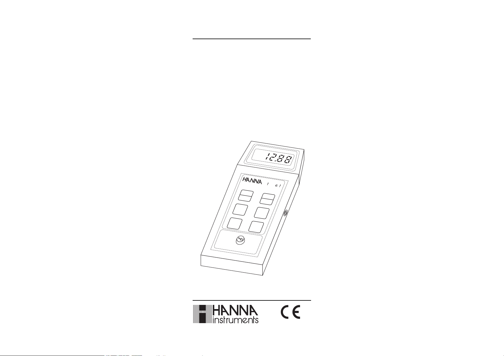
Instruction Manual
HI 8033 - HI 8633
HI 8733 - HI 8734
HI 933000
Portable Multi-Range
Conductivity/TDS Meters
m
S
ins
199.9
m
S
1999
µS
rum
n
s
O
N
O
FF
HI 8633 Conductivity meter
COND.
TEMP.
199.9
µS
19.99
mS
TEMPERATURE
http://www.hannainst.com
These Instruments are in
Compliance with the CE Directives
Page 2
Dear Customer,
Thank you for choosing a Hanna Product. Please read this instruction
manual carefully before using the instrument. It will provide you with
the necessary information for a correct use of the instrument, as well
as a more precise idea of its versatility.
These instruments are in compliance with the
TABLE OF CONTENTSTABLE OF CONTENTS
TABLE OF CONTENTS
TABLE OF CONTENTSTABLE OF CONTENTS
PRELIMINARY EXAMINATION....................................................... 3
GENERAL DESCRIPTION .............................................................. 3
FUNCTIONAL DESCRIPTION & SPECIFICATIONS OF HI 8033 ......... 4
FUNCTIONAL DESCRIPTION & SPECIFICATIONS OF HI 8633 ......... 5
FUNCTIONAL DESCRIPTION & SPECIFICATIONS OF HI 8733 ......... 6
FUNCTIONAL DESCRIPTION & SPECIFICATIONS OF HI 8734 ......... 7
FUNCTIONAL DESCRIPTION & SPECIFICATIONS OF HI 933000 ..... 8
OPERATIONAL GUIDE ................................................................. 9
CALIBRATION ........................................................................... 11
CONDUCTIVITY VERSUS TEMPERATURE CHART ........................... 18
TDS VERSUS TEMPERATURE CHART .......................................... 19
DETERMINING THE TEMPERATURE COEFFICIENT OF A SOLUTION
(HI 8733) .............................................................................. 20
PROBE MAINTENANCE .............................................................. 21
BATTERY REPLACEMENT............................................................ 22
SHOCKPROOF RUBBER BOOTS (for HI 933000 only) ................. 23
ACCESSORIES .......................................................................... 23
WARRANTY .............................................................................. 25
CE DECLARATION OF CONFORMITY ............................................ 26
directives.
2
Page 3

PRELIMINARY EXAMINATIONPRELIMINARY EXAMINATION
PRELIMINARY EXAMINATION
PRELIMINARY EXAMINATIONPRELIMINARY EXAMINATION
Remove the instrument from the packing material and examine it
carefully to make sure that no damage has occurred during shipping.
If there is any noticeable damage, notify your Dealer or the nearest
Hanna office immediately.
Each meter is supplied with:
• Conductivity probe with 1m (3.3') cable
• Calibration screwdriver (except HI 8033)
• Instruction manual
• 9V battery.
Note: Save all packing materials until you are sure that the instru-
ment functions correctly. Any damaged or defective item must
be returned in its original packing materials together with the
supplied accessories.
GENERAL DESCRIPTIONGENERAL DESCRIPTION
GENERAL DESCRIPTION
GENERAL DESCRIPTIONGENERAL DESCRIPTION
HI 8033, HI 8633, HI 8733, HI 8734 and HI 933000 are some of
the most complete and versatile portable conductivity/TDS meters
ever manufactured. Designed with utmost precision and simplicity,
these meters provide for up to 3 or 4 measurement ranges. The
conductivity of a solution depends on the temperature and for this
reason measurements are carried out with reference to a standard
temperature of 25°C. If the solution measured has a different temperature than 25°C, compensation must be performed.
HI 8033, HI 8633 and HI 8734 compensate for temperature manu-
ally.
HI 8733 and HI 933000, with a built-in temperature sensor and
circuitry, automatically compensate for temperature changes.
With HI 8733, the temperature coefficient is adjustable from 0 to
2.5% per degree Celsius depending on the type of solution tested.
For all the other meters the temperature coefficient is fixed at 2%.
3
Page 4
FUNCTIONAL DESCRIPTION &FUNCTIONAL DESCRIPTION &
FUNCTIONAL DESCRIPTION &
FUNCTIONAL DESCRIPTION &FUNCTIONAL DESCRIPTION &
SPECIFICATIONS OF HI 8033SPECIFICATIONS OF HI 8033
SPECIFICATIONS OF HI 8033
SPECIFICATIONS OF HI 8033SPECIFICATIONS OF HI 8033
1
mS
Conductivity meter
ppm
salinity
0-199,9
0-19,990
CaCO
3
OFF
HI 8033
µS
0-1999
µS
0-19,990
µS
2
°C
0
10
34
20
30
40
50
+
5
0
5
-
ins rum n
k%
15
10
10
15
s
1) 3½-digit Liquid Crystal Display
2) Rotary switch
3) Manual temperature compensation knob
4) Calibration knob
Range µS/cm 0.0 to 199.9 / 0 to 1999
mS/cm 0.00 to 19.99
ppm CaCO
TDS 0 to 19990
3
Resolution µS/cm 0.1 / 1
mS/cm 0.01
ppm CaCO
TDS 10
3
Accuracy ±1% Full Scale
(@20°C/68°F) excluding probe error
Typical EMC ±2 % Full Scale
Deviation
Calibration Manual single setpoint through K% knob
Temperature Manual from 0 to 50°C (32 to 122°F)
Compensation with a ß of 2% per degree °C
Probe (included) HI 76301W with 1 m (3.3') screened cable
Environment 0 to 50°C (32 to 122°F);
max 95% RH non-condensing
Battery Type 9 Volt (alkaline)
Life 100 hours of continuous use
Dimensions 185 x 82 x 40 mm (7.3 x 3.2 x1.8")
Weight 355 g (13 oz.)
4
Page 5
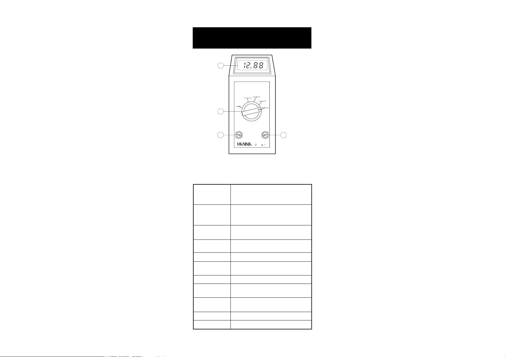
FUNCTIONAL DESCRIPTION &FUNCTIONAL DESCRIPTION &
FUNCTIONAL DESCRIPTION &
FUNCTIONAL DESCRIPTION &FUNCTIONAL DESCRIPTION &
SPECIFICATIONS OF HI 8633SPECIFICATIONS OF HI 8633
SPECIFICATIONS OF HI 8633
SPECIFICATIONS OF HI 8633SPECIFICATIONS OF HI 8633
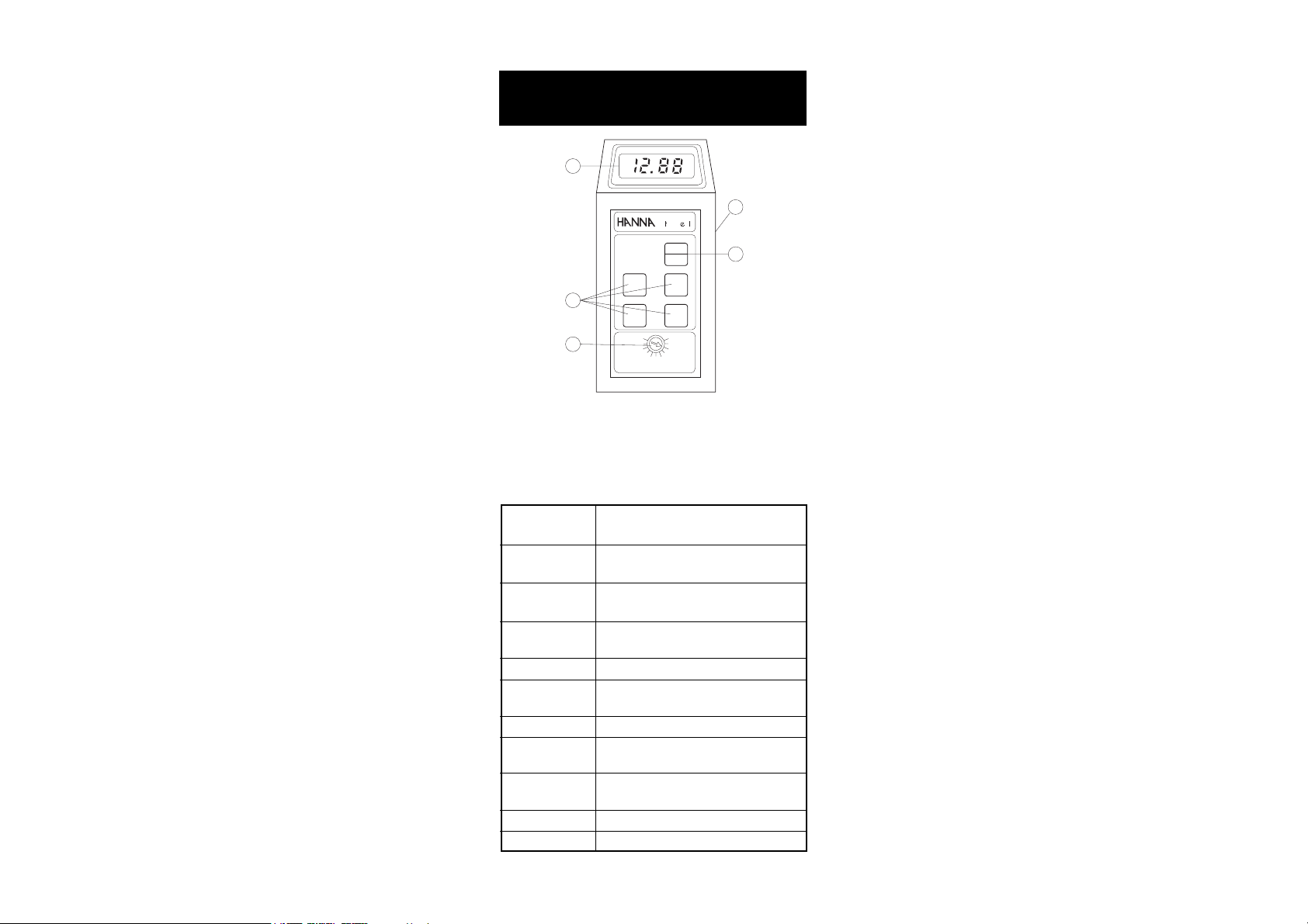
1
3
4
5
mS
ins
COND.
TEMP.
199.9
µS
19.99
mS
TEMPERATURE
rum n
ON
OFF
1999
µS
199.9
mS
HI 8633 Conductivity meter
6
s
2
1) 3½-digit Liquid Crystal Display
2) ON/OFF key
3) Conductivity/temperature selection key
4) Measurement range selection keys
5) Manual temperature compensation knob
6) Calibration trimmer
Range µS/cm 0.0 to 199.9 / 0 to 1999
mS/cm 0.00 to 19.99 / 0.0 to 199.9
Resolution µS/cm 0.1 / 1
mS/cm 0.01 / 0.1
Accuracy ±1% Full Scale
(@ 20°C / 68°F) excluding probe error
Typical EMC ±2 % Full Scale
Deviation
Calibration Manual single setpoint through trimmer
Temperature Manual from 10 to 40°C (50 to 104°F)
Compensation with a ß of 2% per degree °C
Probe (included) HI 76301W with 1 m (3.3') screened cable
Environment 0 to 50°C (32 to 122°F);
max 95% RH non-condensing
Battery Type 9 Volt (alkaline)
Life 100 hours of continuous use
Dimensions 185 x 82 x 45 mm (7.3 x 3.2 x1.8")
Weight 355 g (13 oz.)
5
Page 6
FUNCTIONAL DESCRIPTION &FUNCTIONAL DESCRIPTION &
FUNCTIONAL DESCRIPTION &
FUNCTIONAL DESCRIPTION &FUNCTIONAL DESCRIPTION &
SPECIFICATIONS OF HI 8733SPECIFICATIONS OF HI 8733
SPECIFICATIONS OF HI 8733
SPECIFICATIONS OF HI 8733SPECIFICATIONS OF HI 8733
1
3
4
mS
ins
HI 8733
Conductivity
meter
199.9
µS
19.99
mS
0
0.5
1.51
TEMPERATURE COEFFICIENT
rum n
ON
OFF
1999
µS
199.9
mS
2.5
2
5
s
2
1) 3½-digit Liquid Crystal Display
2) ON/OFF key
3) Measurement range selection keys
4) Automatic Temperature Compensation coefficient knob
5) Calibration trimmer
Range µS/cm 0.0 to 199.9 / 0 to 1999
mS/cm 0.00 to 19.99 / 0.0 to 199.9
Resolution µS/cm 0.1 / 1
mS/cm 0.01 / 0.1
Accuracy ±1% Full Scale
(@ 20°C / 68°F) excluding probe error
Typical EMC ±2 % Full Scale
Deviation
Calibration Manual single setpoint through trimmer
Temperature Automatic from 0 to 50°C (32 to 122°F) with
Compensation an adjustable ß from 0 to 2.5% per °C
Probe (included) HI 7633W ATC with 1 m (3.3') screened cable
Environment 0 to 50°C (32 to 122°F);
max 95% RH non-condensing
Battery Type 9 Volt (alkaline)
Life 100 hours of continuous use
Dimensions 185 x 82 x 45 mm (7.3 x 3.2 x1.8")
Weight 355 g (13 oz.)
6
Page 7
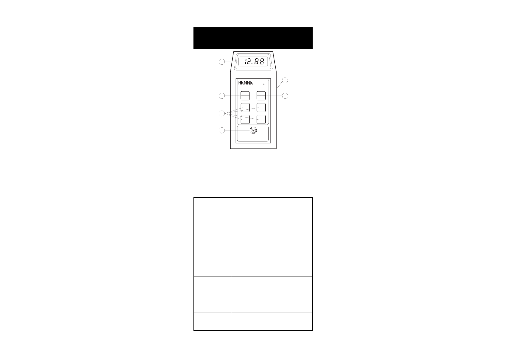
FUNCTIONAL DESCRIPTION &FUNCTIONAL DESCRIPTION &
FUNCTIONAL DESCRIPTION &
FUNCTIONAL DESCRIPTION &FUNCTIONAL DESCRIPTION &
SPECIFICATIONS OF HI 8734SPECIFICATIONS OF HI 8734
SPECIFICATIONS OF HI 8734
SPECIFICATIONS OF HI 8734SPECIFICATIONS OF HI 8734
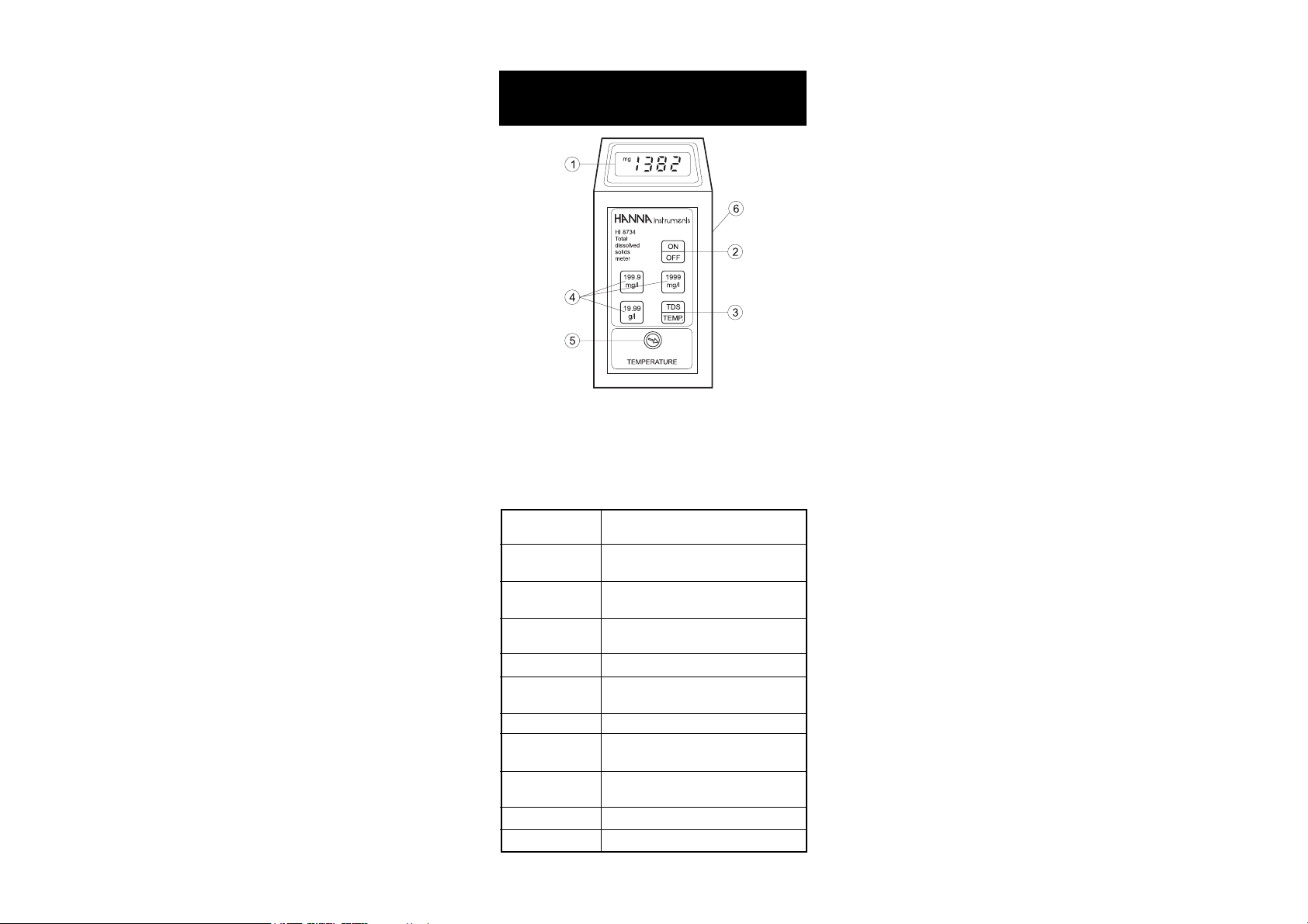
1) 3½-digit Liquid Crystal Display
2) ON/OFF key
3) TDS/temperature selection key
4) Measurement range selection keys
5) Manual temperature compensation knob
6) Calibration trimmer
Range mg/L 0.0 to 199.9 / 0 to 1999
g/L 0.00 to 19.99
Resolution mg/L 0.1 / 1
g/L 0.01
Accuracy ±1% Full Scale
(@ 20°C / 68°F) excluding probe error
Typical EMC ±2 % Full Scale
Deviation
Calibration Manual single setpoint through trimmer
Temperature Manual from 0 to 50°C (32 to 122°F)
Compensation with a ß of 2% per °C
Probe (included) HI 76301W with 1 m (3.3') screened cable
Environment 0 to 50°C (32 to 122°F);
max 95% RH non-condensing
Battery Type 9 Volt (alkaline)
Life 100 hours of continuous use
Dimensions 185 x 82 x 45 mm (7.3 x 3.2 x1.8")
Weight 355 g (13 oz.)
7
Page 8
FUNCTIONAL DESCRIPTION &FUNCTIONAL DESCRIPTION &
FUNCTIONAL DESCRIPTION &
FUNCTIONAL DESCRIPTION &FUNCTIONAL DESCRIPTION &
SPECIFICATIONS OF HI 933000SPECIFICATIONS OF HI 933000
SPECIFICATIONS OF HI 933000
SPECIFICATIONS OF HI 933000SPECIFICATIONS OF HI 933000
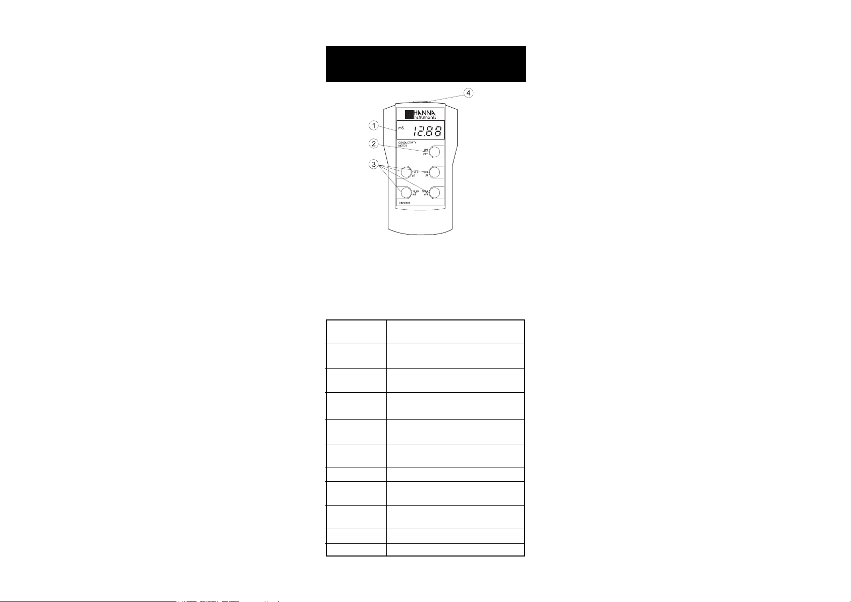
1) 3½-digit Liquid Crystal Display
2) ON/OFF key
3) Measurement range selection keys
4) Probe connector
Range µS/cm 0.0 to 199.9 / 0 to 1999
mS/cm 0.00 to 19.99 / 0.0 to 199.9
Resolution µS/cm 0.1 / 1
mS/cm 0.01 / 0.1
Accuracy ±1% Full Scale
(@ 20°C / 68°F) excluding probe error
Typical EMC ±2% Full Scale
Deviation
Calibration Manual single setpoint through
trimmer in the battery compartment
Temperature Automatic from 10 to 40°C (50 to 104°F)
Compensation with ß of 2% per °C
Probe (included) HI 76302W ATC with 1 m (3.3') screened cable
Environment 0 to 50°C (32 to 122°F);
max 95% RH non-condensing
Battery Type 9 Volt (alkaline)
Life 100 hours of continuous use
Dimensions 143 x 80 x 38 mm (5.6 x 3.2 x1.5")
Weight 360 g (13 oz.)
8
Page 9
OPERATIONAL GUIDEOPERATIONAL GUIDE
OPERATIONAL GUIDE
OPERATIONAL GUIDEOPERATIONAL GUIDE
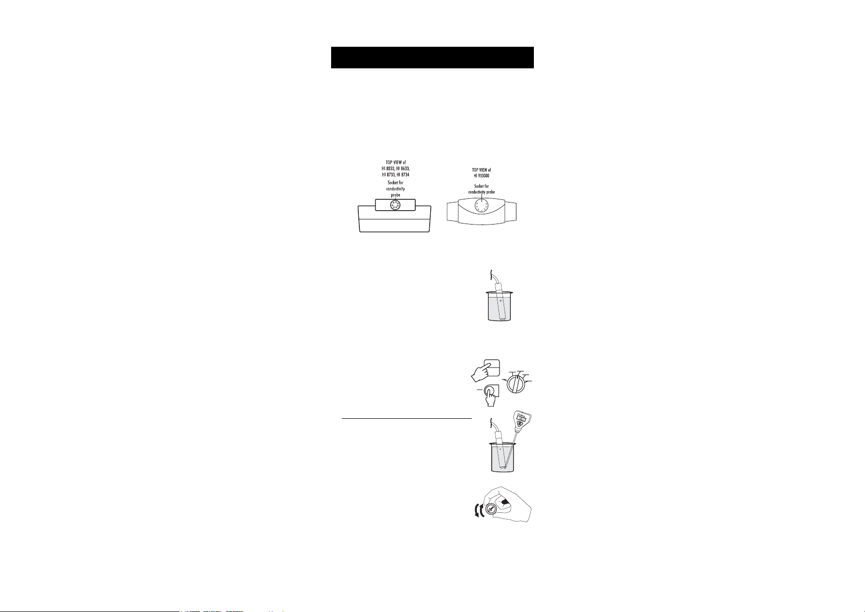
• Each meter is supplied complete with a 9V battery. Slide off the
battery compartment cover on the back of the meter (see page 22).
Install the battery while paying attention to its polarity.
• Connect the probe to the meter securely by aligning the pins with
the socket and pushing the plug in.
With HI 933000, tighten the threaded ring.
• Make sure that the meter has been calibrated before taking any
measurements (see page 11 for calibration procedure).
• Immerse the conductivity probe into the
sample, with the holes on the shaft completely submerged.
If possible, use plastic beakers or containers to minimize any EMC interference.
• Tap the probe lightly on the bottom of the beaker to remove any
air bubbles which may be trapped inside the PVC sleeve.
• Turn the instrument on by pressing the
ON/OFF key or by setting the rotary switch
(for HI 8033 only) to the desired mea-
ON
OFF
ON
OFF
µS
ppm
salinity
0-199,9
0-19,990
CaCO
3
µS
0-1999
OFF
0-19,990
surement range.
•
For HI 8033, HI 8633 and HI 8734 only:
°
Take the temperature of the solution with
a ChecktempC or an accurate thermometer.
µS
C
With HI 8033 set the temperature knob to
the measured value e.g. 20°C.
9
TEMPERATURE
Page 10

With HI 8633 and HI 8734 press the COND/TEMP key (for
HI 8633) or TDS/TEMP (for HI 8734) to display the temperature
and adjust the temperature knob to that of the solution e.g. 20°C.
COND.
TEMP.
TDS
TEMP.
ºC
• Select the appropriate measurement range.
Note: If the display shows only a "1" on the
far left hand side, the meter is out of
range. Select the next (higher) range.
•
For HI 8733:
2.5
Adjust the TEMPERATURE COEFFICIENT
knob to 2% to compensate for the temperature effect of average solutions (to
0
2
0.5
TEMPERATURE COEFFICIENT
1.51
determine exact value for a particular solution, see page 20).
•
For HI 8733 and HI 933000:
Wait for a couple of minutes for the temperature sensor to reach
thermal equilibrium with the sample before taking measurements.
When the sample's temperature is lower than 20°C or higher
than 30°C, allow more time for the thermal equilibrium of the
system to be achieved.
• After the measurement has been completed, the instrument should
be switched off and the probe should be cleaned and dried (see
"Probe Maintenance" on page 21).
10
Page 11

CALIBRATIONCALIBRATION
CALIBRATION
CALIBRATIONCALIBRATION
Accessories needed:
• Use any calibration solution within the meter's range. The
solution should ideally be close to the samples being measured. Use for example HI 7030 or HI 8030, 12880 µS/cm
(=12.88 mS/cm) conductivity solution for HI 8033, HI 8633,
HI 8733 and HI 933000 and HI 7032, 1382 mg/L
(=2764 µS/cm) TDS solution for HI 8734
• ChecktempC or an accurate thermometer with 0.1°C resolution
(not necessary for HI 8733 and HI 933000)
• a small screwdriver.
PROCEDURE FOR HI 8033
0
• Pour sufficient quantity of a conductivity
calibration solution (e.g. HI 7030/
HI 8030) into a beaker to cover the holes
on the probe. If possible, use plastic beakers to minimize any EMC interference.
• Immerse the conductivity probe, making
°C
sure that holes are completely submerged,
and the ChecktempC in the solution.
• Wait for a couple of minutes for thermal
equilibrium to be reached.
• Tap the probe on the bottom, then shake it while rotating to
make sure no air bubbles remain trapped in the sleeve.
• Record the temperature of the HI 7030/HI 8030 calibration
solution from the ChecktempC (e.g. 18°C).
3
0
I 7
H
• Turn the °C knob to 18°C.
µS
salinity
ppm
0-199,9
0-19,990
CaCO
3
µS
• Turn the rotary knob to select 19990 µS/cm
range.
OFF
0-1999
0-19990
µS
• Turn the k% calibration knob until the display shows the conductivity reading at 25°C (see the conductivity vs. temperature chart
on page 18). E.g. @ 25°C, 12880 µS/cm = 12.88 mS/cm.
k%
15
10
+
5
0
5
-
10
mS
15
11
Page 12

• All subsequent measurements will be compensated to 25°C (77°F).
If you prefer to standardize the temperature compensation to
20°C (68°F) rather than 25°C (77°F), leave the °C knob at 18°C
(if the temperature of your solution is 18°C), adjust the trimmer
to read "11.67 mS" (see the conductivity vs. temperature chart at
page 18). All subsequent measurements will be compensated to
20°C.
• The calibration is now complete and the instrument is ready for
use.
The instrument should be re-calibrated at least once a month, or
when the probe or battery is changed.
Note: For more accurate results, it is advisable to use a calibration
solution close to the range to be measured. See the accessories
section on page 23 for a wide selection of conductivity solutions.
PROCEDURE FOR HI 8633
• Pour sufficient quantity of a conductivity
calibration solution (e.g. HI 7030/
HI 8030) into a beaker to cover the holes
on the probe. If possible, use plastic beakers to minimize any EMC interference.
• Immerse the conductivity probe, making
sure that holes are completely submerged,
and the ChecktempC in the solution.
• Wait for a couple of minutes for thermal
equilibrium to be reached.
• Tap the probe on the bottom, then shake it while rotating to make
sure no air bubbles remain trapped in the sleeve.
• Record the temperature of the HI 7030/HI 8030 buffer solution
from the ChecktempC (e.g. 18°C).
• Switch the instrument on by pressing ON/OFF.
• Press COND/TEMP to display the temperature.
• Adjust the TEMPERATURE knob to display 18°C.
°
C
ON
OFF
COND.
TEMP.
HI 7030
TEMPERATURE
12
Page 13

• Press COND/TEMP again to display conductivity
measurement.
COND.
TEMP.
• Select 19.99 mS/cm range by pressing the
19.99
mS
appropriate range key.
• Adjust the calibration trimmer (see page 5, #6) on the side of
the instrument with the calibration screwdriver until the display
shows the conductivity reading at 25°C (see the conductivity vs.
temperature on page 18). E.g. @ 25°C, 12880 µS/cm =
12.88 mS/cm.
m
S
in
s
r
u
m
H
I
n
8
s
6
3
3
C
o
n
d
u
c
tiv
ity
m
e
te
r
COND.
ON
TEMP.
OFF
199.9
1999
µS
µS
1
9
.9
9
1
9
m
9
S
.9
m
S
T
E
M
P
E
R
A
T
U
R
E
mS
• All subsequent measurements will be compensated to 25°C (77°F).
If you prefer to standardize the temperature compensation to
20°C (68°F) rather than 25°C (77°F), leave the TEMPERATURE
knob at 18°C (if the temperature of the solution is 18°C), adjust
the trimmer to read "11.67 mS" (see the conductivity vs. temperature chart on page 18). All subsequent measurements will be
compensated to 20°C.
• The calibration is now complete and the instrument is ready for
use.
The instrument should be re-calibrated at least once a month, or
when the probe or battery is changed.
Note: For more accurate results, it is advisable to use a calibration
solution close to the measurement range . See the accessories
section on page 23 for a wide selection of conductivity solutions.
13
Page 14

PROCEDURE FOR HI 8733
• Pour sufficient quantity of a conductivity
calibration solution (e.g. HI 7030/
HI 8030) into a beaker to cover the holes
on the probe. If possible, use plastic beakers to minimize any EMC interference.
• Immerse the conductivity probe in the
solution, making sure that holes are completely submerged.
• Wait for a couple of minutes for thermal
equilibrium to be reached.
• Tap the probe on the bottom, then shake it while rotating to
make sure no air bubbles remain trapped in the sleeve.
• Switch the instrument on by pressing
ON/OFF.
• Set the temperature coefficient knob to
2% to compensate for the temperature
effect of average solutions (to determine
exact value for a particular solution, see
page 20).
• Select 19.99 mS/cm range by pressing
the appropriate range key.
TEMPERATURE COEFFICIENT
ON
OFF
2.5
0
2
0.5
1.51
19.99
mS
HI 7030
• Adjust the calibration trimmer (see page 6, #5) on the side of
the instrument with the calibration screwdriver until the display
shows "12.88 mS" i.e. the conductivity reading @ 25°C.
m
S
mS
• All subsequent measurements will be compensated to 25°C (77°F).
If you prefer to standardize the temperature compensation to
20°C (68°F) rather than 25°C (77°F), adjust the trimmer to read
"11.67 mS" (see the conductivity vs. temperature chart on page
18). All subsequent measurements will be compensated to 20°C.
• The calibration is now complete and the instrument is ready for
use.
14
Page 15

The instrument should be re-calibrated at least once a month, or
TDS
TEMP.
TDS
TEMP.
when the probe or battery is changed.
Note: For more accurate results, it is advisable to use a calibration
solution close to the range to be measured. See the accessories
section on page 23 for a wide selection of conductivity solutions.
PROCEDURE FOR HI 8734
0
3
0
• Pour sufficient quantity of a TDS calibration solution (e.g. HI 7032) into a beaker
to cover the holes on the probe. If possible, use plastic beakers to minimize any
EMC interference.
• Immerse the TDS probe, making sure
°
C
that holes are completely submerged, and
the ChecktempC in the solution.
• Wait for a couple of minutes for thermal
equilibrium to be reached.
• Tap the probe on the bottom, then shake it while rotating to make
sure no air bubbles remain trapped in the sleeve.
• Record the temperature of the HI 7032 buffer solution from the
ChecktempC (e.g. 18°C).
• Switch the instrument on by pressing
ON/OFF.
ON
OFF
• Press TDS/TEMP to display the temperature.
• Adjust the TEMPERATURE knob to display 18°C.
I 7
H
TEMPERATURE
• Press TDS/TEMP again to display the TDS
measurement.
• Select 1999 mg/L range by pressing the appropriate range key.
15
1999
mg/l
Page 16

• Adjust the calibration trimmer (see page 7,#6) on the side of the
instrument with the calibration screwdriver until the display shows
the TDS reading at 25°C (see the TDS vs. temperature chart on
page 19). E.g. @25°C "1382 mg/L".
T
E
M
P
E
R
A
T
U
R
E
• All subsequent measurements will be compensated to 25°C (77°F).
If you prefer to standardize the temperature compensation to
20°C (68°F) rather than 25°C (77°F), leave the TEMPERATURE
knob to 18°C (if the temperature of the solution is 18°C). Adjust
the trimmer to read "1251 mg/L" (see the TDS vs. temperature
chart on page 19). All subsequent measurements will be compensated to 20°C.
• The calibration is now complete and the instrument is ready for
use.
The instrument should be re-calibrated once a month, or when the
probe or battery is changed.
Note: For more accurate results, it is advisable to use a calibration
solution close to the range to be measured. See the accessories
section on page 23 for a wide selection of TDS solutions.
PROCEDURE FOR HI 933000
• Pour sufficient quantity of a conductivity
calibration solution (e.g. HI 7030/
HI 8030) into a beaker to cover the holes
on the probe. If possible, use plastic beakers to minimize any EMC interference.
• Immerse the conductivity probe in the
solution, making sure that holes are completely submerged.
• Wait for a couple of minutes for thermal
equilibrium to be reached.
• Tap the probe on the bottom, then shake it while rotating to make
sure no air bubbles remain trapped in the sleeve.
16
HI 7030
Page 17

• Switch the instrument on by pressing ON/OFF.
ON
OFF
• Select 19.99mS/cm range by pressing the
appropriate range key.
19.99
mS
• Adjust the calibration trimmer in the battery compartment with a
screwdriver until the display shows "12.88 mS" i.e. the conductivity reading @ 25°C.
mS
9 VOLT BATTERY
• All subsequent measurements will be compensated to 25°C (77°F).
If you prefer to standardize the temperature compensation to
20°C (68°F) rather than 25°C (77°F), adjust the trimmer to read
"11.67 mS" (see the conductivity vs. temperature chart on page
18). All subsequent measurements will be compensated to 20°C.
• The calibration is now complete and the instrument is ready for
use.
The instrument should be re-calibrated once a month, or when the
probe or battery is changed.
Note: For more accurate results, it is advisable to use a calibration
solution close to the range to be measured. See the accessories
section on page 23 for a wide selection of conductivity solutions.
17
Page 18

CONDUCTIVITY VERSUSCONDUCTIVITY VERSUS
CONDUCTIVITY VERSUS
CONDUCTIVITY VERSUSCONDUCTIVITY VERSUS
TEMPERATURE CHARTTEMPERATURE CHART
TEMPERATURE CHART
TEMPERATURE CHARTTEMPERATURE CHART
The conductivity of an aqueous solution is the measure of its ability to
carry an electrical current by means of ionic motion.
The conductivity invariably increases with increasing temperature.
It is affected by the type and number of ions in the solution and by
the viscosity of the solution itself. Both parameters are temperature
dependent. The dependency of conductivity on temperature is expressed as a relative change per degree Celsius at a particular
temperature, commonly as percent per °C.
For manual temperature compensation, refer to the following chart:
°C °F HI 7030 HI 7031 HI 7033 HI 7034 HI 7035 HI 7039
0 32 7150 776 64 48300 65400 2760
5 41 8220 896 65 53500 74100 3180
10 50 9330 1020 67 59600 83200 3615
15 59 10480 1147 68 65400 92500 4063
16 60.8 10720 1173 70 67200 94400 4155
17 62.6 10950 1199 71 68500 96300 4245
18 64.4 11190 1225 73 69800 98200 4337
19 66.2 11430 1251 74 71300 100200 4429
20 68 11670 1278 76 72400 102100 4523
21 69.8 11910 1305 78 74000 104000 4617
22 71.6 12150 1332 79 75200 105900 4711
23 73.4 12390 1359 81 76500 107900 4805
24 75.2 12640 1386 82 78300 109800 4902
2525
25
2525
26 78.8 13130 1440 86 81300 113800 5096
27 80.6 13370 1467 87 83000 115700 5190
28 82.4 13620 1494 89 84900 117700 5286
29 84.2 13870 1521 90 86300 119700 5383
30 86 14120 1548 92 88200 121800 5479
31 87.8 14370 1575 94 90000 123900 5575
HI 8030 HI 8031 HI 8033 HI 8034 HI 8035 HI 8039
(µS/cm) (µS/cm) (µS/cm) (µS/cm) (µS/cm) (µS/cm)
7777
1288012880
14131413
8484
77
12880
1288012880
1413
14131413
7777
8000080000
84
80000
8484
8000080000
111800111800
111800
111800111800
50005000
5000
50005000
For instance, the conductivity values of the calibration solutions at
25°C are 12880 µS/cm, 1413 µS/cm or 5000 µS/cm when using
HI 7030, HI 7031 or HI 7039, respectively.
At 20°C, the values are 11670 µS/cm, 1278 µS/cm or
4523 µS/cm, respectively.
With the solutions at 30°C, the values are 14120 µS/cm, 1548 µS/
cm or 5479 µS/cm, respectively.
18
Page 19

TDS VERSUSTDS VERSUS
TDS VERSUS
TDS VERSUSTDS VERSUS
TEMPERATURE CHARTTEMPERATURE CHART
TEMPERATURE CHART
TEMPERATURE CHARTTEMPERATURE CHART
The TDS value in aqueous solutions is directly proportional to conductivity. The ratio between the two parameters depends on the solution
and usually it is set to a factor of 0.5 (corresponding to a solution of
CaCO
). This means that 1 µS/cm is equal to 0.5 mg/L (ppm) of TDS.
3
For manual temperature compensation, refer to the following chart:
°C °F HI 7032 HI 7036
0 32 758 6.82
5 41 876 7.88
10 50 999 8.99
15 59 1122 10.10
16 60.8 1148 10.33
17 62.6 1173 10.56
18 64.4 1200 10.78
19 66.2 1224 11.01
20 68 1251 11.24
21 69.8 1277 11.47
22 71.6 1303 11.71
23 73.4 1329 11.94
24 75.2 1358 12.18
2525
7777
25
77
2525
7777
26 78.8 1408 12.65
27 80.6 1438 12.89
28 82.4 1461 13.13
29 84.2 1476 13.37
30 86 1515 13.61
31 87.8 1541 13.85
mg/L g/L
(ppm) (ppt)
13821382
12.4112.41
1382
12.41
13821382
12.4112.41
For instance, the TDS values of the calibration solutions at 25°C are
1382 mg/L or 12.41 g/L when using HI 7032 or HI 7036, respectively.
At 20°C, the values are 1251 mg/L or 11.24 g/L, respectively.
With the solutions at 30°C, the values are 1515 mg/L or 13.61 g/L,
respectively.
19
Page 20

DETERMINING THE TEMPERATUREDETERMINING THE TEMPERATURE
DETERMINING THE TEMPERATURE
DETERMINING THE TEMPERATUREDETERMINING THE TEMPERATURE
COEFFICIENT OF A SOLUTION (HI 8733)COEFFICIENT OF A SOLUTION (HI 8733)
COEFFICIENT OF A SOLUTION (HI 8733)
COEFFICIENT OF A SOLUTION (HI 8733)COEFFICIENT OF A SOLUTION (HI 8733)
Highly acidic, alkaline samples or solutions with high salt content
might have a different coefficient than the customary 2% per degree °C.
In order to calculate this coefficient follow the procedure below:
• Immerse the probe of HI 8733 in the sample and adjust the
TEMPERATURE COEFFICIENT knob to 0% (i.e. no compensation).
2.5
0
2
0.5
TEMPERATURE COEFFICIENT
1.51
• Condition the sample and probe to 25°C and note the conductivity reading, C
.
25
• Condition the sample and probe to a different temperature t°C
(approximately 10°C different from 25°C) and note the conductivity reading C
.
t
• The temperature coefficient ß of the solution is calculated as given
by the following formula:
ß = 100 x
(C
(t - 25) x C
- C25)
t
25
The above procedure is suitable for determining the temperature
coefficient in a laboratory or where the temperature of the solution
can be controlled.
If this is not possible (e.g. on-site measurements), the following
procedure can be used providing the sample temperature varies by at
least 5°C or preferably 10°C:
• Immerse the probe of HI 8733 in the test solution and turn the
TEMPERATURE COEFFICIENT knob to 0% (no compensation).
• Check the conductivity reading and record the value. Make sure
the reading is stable, i.e. no greater variations than ±0.2 mS/
cm within a minute.
• Repeat the procedure when the temperature of the test solution
has changed by at least 5°C. Wait for the conductivity reading to
stabilize.
• Adjust the TEMPERATURE COEFFICIENT knob until the display
shows the same value as recorded earlier.
• The value indicated by the knob is the temperature coefficient of
the solution.
20
Page 21

PROBE MAINTENANCEPROBE MAINTENANCE
PROBE MAINTENANCE
PROBE MAINTENANCEPROBE MAINTENANCE
Rinse the probe with tap water after every series of
measurements. If a more thorough cleaning is required,
remove the PVC sleeve and
clean the probe with a cloth or
a non-abrasive detergent.
When reinserting the sleeve
onto the probe, be sure that
the sleeve is in the right direction with the four holes towards
the cable end.
After cleaning the probe, recalibrate the instrument.
The probe body is in PVC. For
this reason it must never come
into close contact with a heat
source. If the probe is exposed
to high temperatures (above
50°C/122°F), the rings might
become loose or detached, resulting in a serious impairment
of the probe. In such cases,
the probe has to be replaced.
21
Page 22

OFF
BATTERY REPLACEMENTBATTERY REPLACEMENT
BATTERY REPLACEMENT
BATTERY REPLACEMENTBATTERY REPLACEMENT
When the battery becomes weak the meters will display "V" or an
additional blinking decimal point (HI 8733).
V
When the low battery indicator appears, the battery has only a few
hours left. A low battery will result in unreliable measurements.
It is recommended that the battery be replaced immediately.
Battery replacement must only take place in a non-hazardous area
using an alkaline 9V battery.
Slide off the battery compartment cover at the rear of the meter and
replace the 9V battery with a new one. Make sure the battery contacts
are tight and secure before replacing the cover.
HI 933000
9 VOLT BATTERY
HI 8033
HI 8633
HI 8733
HI 8734
BATTERY
SLIDE
22
SLIDE
OFF
Page 23

SHOCKPROOF RUBBER BOOTSSHOCKPROOF RUBBER BOOTS
SHOCKPROOF RUBBER BOOTS
SHOCKPROOF RUBBER BOOTSSHOCKPROOF RUBBER BOOTS
((
for for
HH
I I
(
for
((
for for
H
I
HH
I I
933000 933000
933000
933000 933000
onlyonly
only
onlyonly
These rubber boots are specially
made to prolong the life of your
instrument and to prevent damage due to accidental bangs and
falls.
They measure 155 x 90 x 45 mm
mS
CONDUCTIVITY
METER
(6.1x3.5x1.8") and are available
HI933000
199.9
µS
19.99
mS
in two different colors:
HI 710007 = blue
HI 710008 = orange.
ACCESSORIESACCESSORIES
ACCESSORIES
ACCESSORIESACCESSORIES
CONDUCTIVITY & TDS BUFFER SOLUTIONS
HI 7030L 12880 µS/cm (µmho/cm), 460mL
HI 7030M 12880 µS/cm (µmho/cm), 230mL
HI 7031L 1413 µS/cm (µmho/cm), 460mL
HI 7031M 1413 µS/cm (µmho/cm), 230mL
HI 7033L 84 µS/cm (µmho/cm), 460 mL
HI 7033M 84 µS/cm (µmho/cm), 230 mL
HI 7034L 80000 µS/cm (µmho/cm), 460mL
HI 7034M 80000 µS/cm (µmho/cm), 230mL
HI 7035L 111800 µS/cm (µmho/cm), 460mL
HI 7035M 111800 µS/cm (µmho/cm), 230mL
HI 7039L 5000 µS/cm (µmho/cm), 460mL
HI 7039M 5000 µS/cm (µmho/cm), 230mL
HI 7032L 1382 ppm (mg/L), 460 mL
HI 7032M 1382 ppm (mg/L), , 230 mL
HI 7036L 12.41 ppt (g/L), 460 mL
HI 7036M 12.41 ppt (g/L), 230 mL
))
)
))
ON
OFF
1999
µS
199.9
mS
23
Page 24

A
CONDUCTIVITY BUFFER SOLUTIONS IN FDA APPROVED
BOTTLES
HI 8030L 12880 µS/cm (µmho/cm), 460 mL
HI 8031L 1413 µS/cm (µmho/cm), 460 mL
HI 8033L 84 µS/cm (µmho/cm), 460 mL
HI 8034L 80000 µS/cm (µmho/cm), 460 mL
HI 8035L 111800 µS/cm (µmho/cm), 460 mL
HI 8039L 5000 µS/cm (µmho/cm), 460 mL
CONDUCTIVITY PROBES
HI 76301W 4-ring conductivity/TDS probe with 1 m (3.3') screened
cable (for HI 8033, HI 8633 and HI 8734)
19,5mm
DIA
0.77"
85mm
3.34"
118.5mm
4.66"
HI 76302W 4-ring conductivity probe with built-in temperature
sensor and 1 m (3.3') screened cable (for
HI 933000)
HI 7633W 4-ring conductivity probe with built-in temperature
sensor and 1 m (3.3') screened cable (for HI 8733)
11.5mm
0.45"
DI
19,5mm
DIA
0.77"
85mm
118.5mm
4.66"
3.34"
11.5mm
0.45"
DIA
OTHER ACCESSORIES
HI 710001 Soft carrying case for HI 8033, HI 8633, HI 8733,
HI 8734 and HI 933000 measuring 230x100x50 mm
CHECKTEMPC Electronic thermometer (range: -50.0 to 150.0°C)
HI 721313 Rugged carrying case for HI 8733 and HI 8633 measur-
ing 340 x 230 x 90 mm complete with conductivity
calibration solution (HI 7030S, 120 mL) and screwdriver
24
Page 25

HI 721314 Rugged carrying case for HI 8734 measuring
340x230x90 mm complete with TDS calibration solu-
tion (HI 7032S, 120 mL) and screwdriver
HI 731326 20 small screwdrivers, length 90 mm, for calibration
purposes (except for HI 8033)
HI 710007 Blue shockproof rubber boot for HI 933000
HI 710008 Orange shockproof rubber boot for HI 933000
HI 710009 Blue rubber boot for HI 8033, HI 8633, HI 8733 and
HI 8734
HI 710010 Orange rubber boot for HI 8033, HI 8633, HI 8733
and HI 8734
MANCONDR2 Instruction manual
WARRANTYWARRANTY
WARRANTY
WARRANTYWARRANTY
All Hanna Instruments meters are warranted for two years against
defects in workmanship and materials when used for their intended
purpose and maintained according to instructions. The electrodes
and the probes are warranted for a period of six months. This
warranty is limited to repair or replacement free of charge.
Damages due to accident, misuse, tampering or lack of prescribed
maintenance are not covered.
If service is required, contact the dealer from whom you purchased
the instrument. If under warranty, report the model number, date of
purchase, serial number and the nature of the failure. If the repair is
not covered by the warranty, you will be notified of the charges
incurred. If the instrument is to be returned to Hanna Instruments,
first obtain a Returned Goods Authorization number from the Customer Service department and then send it with shipping costs prepaid.
When shipping any instrument, make sure it is properly packaged for
complete protection.
To validate your warranty, fill out and return the enclosed warranty
card within 14 days from the date of purchase.
All rights are reserved. Reproduction in whole or in part is prohibited
without the written consent of the copyright owner,
Hanna Instruments Inc., 584 Park East Drive, Woonsocket, Rhode
Island, 02895 , USA.
Hanna Instruments reserves the right to modify the design, construction and appearance of its products without advance notice.
25
Page 26

CE DECLARATION OF CONFORMITYCE DECLARATION OF CONFORMITY
CE DECLARATION OF CONFORMITY
CE DECLARATION OF CONFORMITYCE DECLARATION OF CONFORMITY
Recommendations for Users
Before using these products, make sure that they are entirely suitable for the environment in which they are used.
Operation of these instruments in residential area could cause unacceptable interference to radio and TV equipment, requiring the operator to take
all necessary steps to correct interferences.
The metal band at the end of the probe is sensitive to electrostatic discharges. Avoid touching this metal band at all times.
During calibration of the instruments, ESD wrist straps should be worn to avoid possible damage to the probe by electrostatic discharge.
Any variation introduced by the user to the supplied equipment may degrade the instruments' EMC performance.
To avoid electrical shock, do not use these instruments when voltages at the measurement surface exceed 24VAC or 60VDC.
Use plastic beakers to minimize any EMC interferences.
To avoid damage or burns, do not perform any measurement in microwave ovens.
26
Page 27

OTHER PRODUCTS FROM HANNAOTHER PRODUCTS FROM HANNA
OTHER PRODUCTS FROM HANNA
OTHER PRODUCTS FROM HANNAOTHER PRODUCTS FROM HANNA
• CALIBRATION AND MAINTENANCE SOLUTIONS
• CHEMICAL TEST KITS
• CHLORINE METERS
• DISSOLVED OXYGEN METERS
• HYGROMETERS
• ION SPECIFIC METERS (Colorimeters)
• MAGNETIC STIRRERS
• Na/NaCl METERS
• pH/ORP/Na ELECTRODES
• pH/ORP METERS
• PROBES (DO, µS/cm, RH, T, TDS)
• PUMPS
• REAGENTS
• SOFTWARE
• THERMOMETERS
• TITRATORS
• TRANSMITTERS
• TURBIDITY METERS
• Wide Range of Accessories
Most Hanna meters are available in the following formats:
• BENCH-TOP METERS
• POCKET-SIZED METERS
• PORTABLE METERS
• PRINTING/LOGGING METERS
• PROCESS METERS (Panel and Wall-mounted)
• WATERPROOF METERS
• METERS FOR FOOD INDUSTRY
For additional information, contact your dealer or the nearest Hanna
Customer Service Center. You can also e-mail us at:
tech@hannainst.com.
27
Page 28

HANNA LITERATUREHANNA LITERATURE
HANNA LITERATURE
HANNA LITERATUREHANNA LITERATURE
Hanna publishes a wide range of catalogs and handbooks for an equally wide range of applications.
The reference literature currently covers areas such
as:
• Water Treatment
• Process
• Swimming Pools
• Agriculture
• Food
• Laboratory
• Thermometry
and many others. New reference material is constantly being added to the library.
For these and other catalogs, handbooks and leaflets, contact your dealer or the Hanna Customer
Service Center nearest to you. To find the Hanna
Office in your vicinity, check our home page at
www.hannainst.com.
MANCONDR2
06/97
http://www.hannainst.com
 Loading...