

Page 1

Microlab F.A.M.E.
USER MANUAL
Version 2.0
Page 2

P/N 610520/02 05/01
Important Notice
This manual may not be used or reproduced in any way whatsoever without the express
written consent of Hamilton Bonaduz AG.
Copyright ã 1995, 1996, 1997, 1998, 1999 Hamilton Bonaduz AG, All Rights Reserved.
Microlab is a registered trade mark of Hamilton Bonaduz AG.
IBM, OS/2, DATABASE 2 and DB2 are registered trademarks of International Business
Machines Corporation.
MICROTITER is a registered trademark of Dynatech Laboratories.
Page 3

Microlab F.A.M.E. User Manual V2.0 ——————————————————————————— Master Table of Contents ——
Master Table of Contents
1 - ML F.A.M.E. Overview .................................................................1
Cook Book - Chapter 2 to 8
2 - Cook Book Introduction............................................................25
3 - ML F.A.M.E. Methods ................................................................27
4 - Daily Work Routine....................................................................41
5 - Test Results & ML F.A.M.E. Traces............................................55
6 - Instrument Status ......................................................................63
7 - ML F.A.M.E. Verification.............................................................65
8 - ML F.A.M.E. Maintenance .........................................................69
Reference Guide - Chapter 9 to 17
9 - Reference Guide Introduction...................................................81
10 - ML F.A.M.E. Methods ..............................................................83
11 - Daily Work Routine................................................................105
12 - Test Results & ML F.A.M.E. Traces........................................129
13 - ML F.A.M.E. Functions & Requirements ...............................137
14 - ML F.A.M.E. Verification.........................................................147
15 - ML F.A.M.E. Maintenance .....................................................169
16 - Technical Specifications........................................................183
17 - Troubleshooting & Error Handling........................................199
Appendices - A1 to A8
A1 - Error & Trace Codes Messages............................................213
A2 - Glossary................................................................................237
A3 - Frequently Asked Questions ................................................247
A4 - Anomalies .............................................................................249
A5 - Forms....................................................................................251
A6 - News Letters .........................................................................261
A7 - User Manual Update Information .........................................263
A8 - Index .....................................................................................265
P/N 610520/02 05/01
Page 4

Microlab F.A.M.E. User Manual V2.0 ——————————————————————————— Master Table of Contents ——
P/N 610520/02 05/01
Page 5

Microlab F.A.M.E. User Manual V2.0 —————————————————————————— ML F.A.M.E. Overview ——
Chapter
1 ML F.A.M.E. Overview
Table of Contents
1.1 - About the Microlab F.A.M.E. ....................................................2
1.1.1 - Basic Concepts ..................................................................2
1.2 - Using This Manual....................................................................3
1.2.1 - User Manual Symbols ........................................................3
1.3 - ML F.A.M.E. Components ........................................................4
1.3.1 - The ML F.A.M.E. Instrument ...............................................4
1.3.2 - The ML F.A.M.E. Workstation .............................................9
1.4 - General Information ...............................................................12
1.4.1 - Warranty............................................................................12
1.4.2 - Ordering Information ........................................................13
1.4.3 - Definition of Terms............................................................17
1.4.4 - Safety Precautions and Hazards......................................17
P/N 610520/02 05/01
1-1
Page 6

Microlab F.A.M.E. User Manual V2.0 —————————————————————————— ML F.A.M.E. Overview ——
1.1 About the Microlab F.A.M.E.
1.1.1 Basic Concepts
The Microlab F.A.M.E. (ML F.A.M.E.) is a diagnostic instrument
used to analyze blood samples for the presence of certain biological elements.
This analysis is performed using the ELISA (Enzyme Linked
Immuno Sorbent Assay) testing process. This process requires
samples to be manipulated in various ways, i.e. incubating, washing, dispensing, mixing, photometric measurement, etc.
The ML F.A.M.E. has been developed with a modular design, incorporating all functions necessary to perform these sample manipulations.
The test process is controlled by a highly developed software
pakkage allowing:
r Simultaneous processing of tests from different manufacturers.
r Easy adaptation of various tests using the ML F.A.M.E. Method
Editor.
r Automatic schedule optimization and work list visualization.
r Full traceability and documentation of sample processing and
of individual instrument functions.
1.1.1.1 Intended Use
The intended use of the ML F.A.M.E. is to process microplate
based ELISA assays for screening blood and blood products for
the presence of any blood-borne pathogen, primarily in screening
centers, plasma centers, hospitals, public health centers and reference laboratories.
1.1.1.2 ML F.A.M.E. Operator
Any persons operating the ML F.A.M.E. and ML F.A.M.E. workstation must have attended a certified training course. Any departure
from the following texts could lead to erroneous results or ML
F. A.M . E . m a l fu n c ti o n .
1-2
P/N 610520/02 05/01
Page 7

Microlab F.A.M.E. User Manual V2.0 —————————————————————————— ML F.A.M.E. Overview ——
1.2 Using This Manual
This manual has been developed for use with ML F.A.M.E. version
2.0 and should not be used with any other software version unless
previously announced by the supplier.
The documentation set has been designed to allow various levels
of ML F.A.M.E. operator to access the required information as they
progress in their knowledge of the environment.
This has been achieved using a three part structure:
r ML F.A.M.E. Overview
The ML F.A.M.E. Overview gives general information about
the ML F.A.M.E., its computer environment, functions and
intended use.
r Cook Book
The Cook Book defines the ML F.A.M.E. operator related
tasks in a step-by-step guide.
In each section there is an introduction explaining the task
then a table structure defining a question and then an
explanation of the procedures needed to achieve this task.
Where necessary there are “Notes” and “Attention”
paragraphs to bring certain information to the ML F.A.M.E.
operator. These paragraphs are positioned in the left column
to avoid any interruption in the flow of the step by step
process.
r Reference Guide
The Reference Guide gives full technical information on all
functions of the ML F.A.M.E. and is designed to be used as
both support for the Cook Book (through extensive cross
referencing) and as a stand alone reference work.
“Notes” and “Attention” paragraphs, similar to those used in
the Cook Book are also used in the Reference Guide.
1.2.1 User Manual Symbols
P/N 610520/02 05/01
ATTENTION
ATTENTION: Any special problems, warnings or important information will be accompanied by this symbol. Read these carefully as
they can easly help to understand particular issues.
NOTE: This is used to give information to the ML F.A.M.E. operator
that is useful but not essential to the task at hand. Read these carefully as they can easly help to understand particular issues.
NOTE
1-3
Page 8
Microlab F.A.M.E. User Manual V2.0 —————————————————————————— ML F.A.M.E. Overview ——
(
)
1.3 ML F.A.M.E. Components
The ML F.A.M.E. consists of two parts:
r The ML F.A.M.E. Instrument.
and
r The ML F.A.M.E. Workstation (including ML F.A.M.E. software).
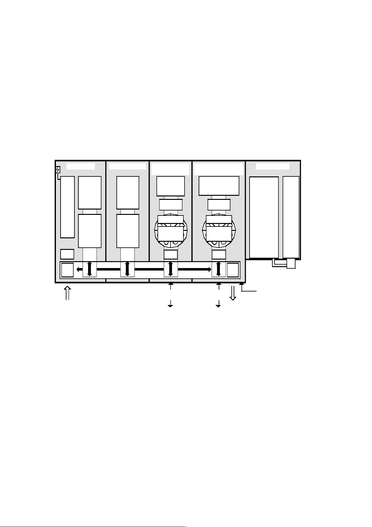
1.3.1 The ML F.A.M.E. Instrument
Entr y Mo dul e Incubator Module
Power
Supply
230/
115 V
Plate
Barco de
Reader
Ent r y
Lif t/
Stac k
MTP Loading
max 4 per stack
Rear
Incubator
To wer
5 Slo ts
temper atur e-
cont r ol led
Fr ont
Incubator
To wer
5 Slo ts
ambi ent
temperature
Module
Mai n Shuttle Rail
Trans port
Washer/ Dispenser
(Di spenser/Photometer)
Photometer
Mi xer
Dispen ser
Re age nt
Cont a iner
1818
Carousel
Reag ent
Ba rc ode
Reader
Exi t
Stack/
Manipul ation
Posi t i o n
Module
Trans port
Draw erDr awe r
MTP Exit
Re ar
Incubat or
Tower
5 Slot s
temp erat ur e-
controlled
Front
Incubat or
Tower
5 Slot s
temp erat ur e-
controlled
Module
Mo du l e
Was h e r
24 ch annel
man i fo l d
Mixer
Di sp ens er
Reagent
Cont ai ner
Caro us el
Reagen t
Barcode
Rea der
Module
Trans port
Trans port
Reagent Re agent
Figure 1.1 16/20 configuration (top view)
The primary functions of the ML F.A.M.E. include:
Cont ai ner St ackEnd Module
Wash/Rinse
Fl ui d
Containers
1-4
PC Connectio n
Ext.
Pump
Stati on
r Positive plate identification.
r Incubation (temperature-controlled or ambient).
r Washing (with liquid level detection).
r Dispensing (including positive reagent identification and liquid
level detection).
r Photometric measurement.
1.3.1.1 Configurations
All instrument configurations consist of a combination of four different modules.
1-4
P/N 610520/02 05/01
Page 9

Microlab F.A.M.E. User Manual V2.0 —————————————————————————— ML F.A.M.E. Overview ——
r Entry Module - 10 incubation slots
r Incubator Module - 10 incubation slots
r Washer/Dispenser Module with External Pump Station
r End Module
These four basic modules connected to the chassis, plus a container stack, complete the basic instrument configuration 16/20 - 16
reagent positions and 20 incubator slots.
By adding an extra incubator module and/or an extra washer/dispenser module to the chassis, the following three instrument configurations are also possible:
r 16/30 - 2 incubator modules giving 30 incubation slots
r 24/20 - 2 washer/dispenser modules giving 24 reagent positions
r 24/30 - 2 incubator modules and 2 washer/dispenser modules
Upgrade from one configuration to a higher specification instrument is possible in the field.
1.3.1.2 Entry Module
The main functions of the Entry Module are:
r Loading of the plates
r Plate barcode reading (positive plate identification)
r Incubation
The Entry Module consists of the following components:
1.3.1.2.1 Entry Section
The entry platform is used to load plates onto the instrument. All
plates are placed manually onto the entry platform.
There are two ways of loading plates:
1 Place a single plate directly onto the entry platform. 2 Place an entry stack (which accommodates up to 4 plates) onto
the entry platform.
P/N 610520/02 05/01
1.3.1.2.2 Plate Barcode Reader
The function of the plate barcode reader is to identify barcodes on
the plates. Barcode information is also used to select the test
method and or kit lot to be used.
After reading, the plate is transported automatically, according to
the selected method, to the defined modules for processing, e.g.
incubator, washer, etc.
1-5
Page 10

Microlab F.A.M.E. User Manual V2.0 —————————————————————————— ML F.A.M.E. Overview ——
1.3.1.2.3 Incubators
NOTE
Slots within the same incubator
tower cannot be individually
programmed. However, each
slot is individually temperaturecontrolled.
The Entry Module contains two incubator towers each with 5 incubation slots.
The front tower is used for ambient temperature incubation only.
The rear tower is used for ambient temperature or for temperaturecontrolled incubation.
The temperature can be set between ambient and 45°C. A plate
can be loaded individually into each slot.
1.3.1.2.4 Power Distribution
The power supply for all the modules is built into the Entry Module.
The mains power connector and the on/off switch are located on
the left hand side of this module towards the rear.
The primary and secondary protection switches (circuit breakers),
and the voltage selector switch (230/115V) are also located in this
area, behind the instrument side panel.
1.3.1.3 Incubator Module
NOTE
Slots within the same incubator
tower cannot be individually programmed. However, each slot is
individually temperature controlled.
1.3.1.4 Washer/Dispenser Module
1.3.1.4.1 Washer
The Incubator Module contains two temperature-controlled incubator towers each with 5 incubation slots.
The temperature of both towers is programmable up to 70°C (maximum allowed temperature difference between the two towers:
25°C).
An individual plate can be loaded into each incubator slot.
The main functions of the Washer/Dispenser Module are:
r Plate washing
r Dispensing of reagents
r Mixing (shaking of plates)
Washer/Dispenser Modules consist of the following components:
The washer comprises a 24-channel manifold consisting of 3 rows
of 8 needles. Each of the 24 wells is washed simultaneously.
1-6
An adjustment of the manifold liquid level detection system is executed automatically during every cold start of the system.
Each needle has liquid level detection. If a well cannot be properly
washed, the liquid level detector produces an error which is documented as a message in a trace file.
P/N 610520/02 05/01
Page 11

Microlab F.A.M.E. User Manual V2.0 —————————————————————————— ML F.A.M.E. Overview ——
Three different wash solutions (up to 3 liters each) and one rinse
fluid (up to 3 liters) can be loaded into the container stack situated
next to the End Module. All wash fluid containers have liquid level
detection. All wash functions and liquid definitions are programmable by the user software in the Method Definition. For example:
r Wash mode
r Number of wash cycles
r Soak time
r Volume of liquid
r Solution name
1.3.1.4.2 Waste Container
The waste container holds the fluid that is aspirated from the plates
during washing and has a capacity of 10 liters. A liquid level detector is incorporated in the waste cap. When the container is full, a
message appears on the workstation screen. Exchanging of waste
containers is possible without interrupting instrument operation.
1.3.1.4.3 External Water Separator
The external water separator holds fluid that is expelled from the
venting tube.
1.3.1.4.4 Dispenser
A single channel dispenser, using disposable syringes and reagent
containers dispenses the required reagents into the plates.
Carry-over is eliminated by the use of Hamilton Reagent Container
Systems with dedicated syringes for each reagent liquid.
Liquid Level Detection is used during the reagent’s distribution process.
1.3.1.4.5 Reagent Container System
Each Reagent Container System consists of:
r A reagent container
r A dedicated disposable syringe
r A barcode label
P/N 610520/02 05/01
In total, 8 reagent container systems can be positioned in segments on the reagent container carousel. The carousel is then
placed into the reagent drawer.
Several reagent container carousels can be utilized. Single reagent
container systems or complete reagent container carousels can be
exchanged and kept in a refrigerator.
1-7
Page 12

Microlab F.A.M.E. User Manual V2.0 —————————————————————————— ML F.A.M.E. Overview ——
1.3.1.4.6 Reagent Container Identification
Each reagent container is identified by a clear text label and a barcode. A barcode reader located in each reagent drawer identifies
the reagents.
Barcodes are supplied for containers. You may use other barcode
labels providing that they comply with ML F.A.M.E. specifications,
see Reference Guide Section 16.3.2 on page 193.
1.3.1.4.7 Mixer
The mixer is used for horizontal shaking of the plate in the lengthwise direction. The mix intensity and the mix time are programmable.
1.3.1.5 End Module
The main functions of the End Module are:
r Reagent dispensing
r Photometric measurement
r Mixing (shaking of the plate)
The Exit Stack is also located in this module allowing plates to be
removed from the instrument.
The End Module comprises the following components:
1.3.1.5.1 Dispenser
The function of the dispenser is the same as the one in the Washer/
Dispenser module.
1.3.1.5.2 Mixer
The mixer is identical to the one in the Washer/Dispenser module.
1.3.1.5.3 Photometer
The photometer has 8 measuring channels (i.e. 8 wells can be
measured simultaneously) and one additional reference channel.
There are 5 filters incorporated with the following wavelengths:
r 340 nm
1-8
r 405 nm
r 450 nm
r 492 nm
r 620 nm
Up to 8 filters can be used. These may have wavelengths ranging
from 340 nm to 750 nm.
P/N 610520/02 05/01
Page 13

Microlab F.A.M.E. User Manual V2.0 —————————————————————————— ML F.A.M.E. Overview ——
The following parameters are programmable via the user software:
r Measurement wavelength
r Reference wavelength
1.3.1.5.4 Exit Stack
The exit stack is where the instrument stores finished plates (i.e.
plates which have had all processing steps performed on them).
From here the plates can be removed and disposed of.
Approximately 10 plates can be stored in the exit stack. Bristles
hold the plates in place in the exit stack. A sensor controls the exit
status.
If the stack is nearly full, a warning message is displayed by the
user software. Plates can be removed at any time without interrupting processing.
1.3.2 The ML F.A.M.E. Workstation
The ML F.A.M.E. Workstation is an IBM compatible personal computer (PC), to the specification listed in section 1.3.2.1 en la página
1-9, running the IBM operating system OS/2 WARP with IBM’s DB2/
2 and version 2.0 of the ML F.A.M.E. software.
1.3.2.1 The Computer
The specification of the personal computer required for use with
the ML F.A.M.E. is listed in Reference Guide Section 16.4 on page
196 and it is highly recommended to use a system as similar as
possible.
1.3.2.2 The Operating System
An operating system is a software application allowing the system
operator to access installed software and to write and read information to a storage device, i.e. floppy or fixed disk.
This software application has been designed and created to run
with IBM’s OS/2 operating system (WARP). It also utilizes IBM’s
data storage retrieval system DB2/2.
P/N 610520/02 05/01
OS/2 is a Graphic User Interface (GUI) operating environment
which means the ML F.A.M.E. operator can access the required
functions using an object oriented control method, i.e. to access a
function the ML F.A.M.E. operator will physically select the command for that function using a pointing device, e.g. a mouse.
For further information on using OS/2 and DB2/2 please consult
the supplier or the documentation supplied with the product.
1-9
Page 14
Microlab F.A.M.E. User Manual V2.0 —————————————————————————— ML F.A.M.E. Overview ——
1.3.2.3 The ML F.A.M.E. Software
NOTE
The standard Microlab F.A.M.E.
software does not include the
Active Kit Lot Check and Sample
and Reagent Addition Monitoring
(SRAM) features. If Hamilton
users need these features,
authorization from Hamilton and
OCD is required for blood banks
in specific territories. Please
contact the Product Manager at
Hamilton Bonaduz to obtain the
special disk set.
The ML F.A.M.E. software is an application with various access
rights assigned to the various levels of ML F.A.M.E. operator giving
them software control on a need-to-use basis.
Main features of the software include:
r Full operations tracing (ML F.A.M.E. operator, ML F.A.M.E. soft-
ware and ML F.A.M.E. functions and actions).
r Full sample tracing (from entire plates to individual wells).
r Temporary storage of processed plates’ data.
r Method definition and editing.
r Scheduling with re-scheduling options.
r Graphical representation of daily work routine.
ATTENTION
For further information on
installation please see the
separate Installation Guide. It is
the responsibility of the
laboratory manager which
installation options are selected.
ATTENTION
With this option on it is possible
to operate an “un-verified”
instrument.
1.3.2.4 Installation Options
r Extensive error handling and recovery routines.
r Complete instrument maintenance and verification procedures.
During the installation procedure for the ML F.A.M.E. software a
number of features exist allowing the customizing of the installation.
The installation options are as follows:
r Verification Restrictive:
With this option selected the ML F.A.M.E. operator will be
prompted when trying to start a run, if there are verification procedures required. It is not possible to run ML F.A.M.E. if the
required verification for any module is not completed. The only
exception is if the ML F.A.M.E. operator is asked whether or not
to run verification on an incubator slot and answers "no" then
that slot will be locked, although a run can be started.
r Verification Non-restrictive:
With this option selected the ML F.A.M.E. operator will be
prompted when trying to start a run, if there are verification procedures required. It is still possible to use ML F.A.M.E. modules
if the required verification for that module is not completed, e.g,
if the ML F.A.M.E. operator is asked whether or not to run verification on an incubator slot and answers "no" then that slot will
be not locked, however, the error status of a test will be set to
trace and all test traces will contain a warning indicating the
required function was not verified when requested.
1-10
r Plate Access Off:
With this option selected the ML F.A.M.E. software must find the
pipetting information on the first try or else the plate will not be
accepted for processing. No other options are allowed.
P/N 610520/02 05/01
Page 15
Microlab F.A.M.E. User Manual V2.0 —————————————————————————— ML F.A.M.E. Overview ——
r Plate Access On:
With this option selected the ML F.A.M.E. software will allow the
ML F.A.M.E. operator to process plates when no pipetting infor-
ATTENTION
Please ensure that the correct
sample barcodes are entered.
mation is found. Options include retry or searching for the barcode information along a path, using an editor to include or
exclude wells or to enter the well barcodes after plate loading.
Sample barcodes from the plate
barcode file are write protected.
r Active Kit Lot Check:
With this option selected the master kit lot number included in
the plate barcode or in the pipetting file will be checked against
the defined one. The kit lot file must be provided by the higher
system, no access is given to the editor.
ATTENTION
Please ensure that the correct kit
lot data is defined in the kit lot
editor.
r Kit Lot Documentation:
With this option selected the ML F.A.M.E. operator will have
access to the Kit Lot Editor allowing editing or creating of kit lot
information file. However, the defined kit lot will be documented,
but no check is made of the loaded lot.
r User Access Editor Off:
ATTENTION
Please ensure that the default
users are deleted and the
correct lab specific users and
access rights are defined.
Disables the User Access Editor.
r User Access Editor On:
Enables the User Access Editor where it is possible to establish a list of ML F.A.M.E. operators and their security level.
P/N 610520/02 05/01
1-11
Page 16

Microlab F.A.M.E. User Manual V2.0 —————————————————————————— ML F.A.M.E. Overview ——
1.4 General Information
1.4.1 Warranty
HAMILTON warrants this product to be free of defects in material
and workmanship for a period of 12 months from the date of delivery.
HAMILTON or an authorized HAMILTON representative will repair
or replace, at its option and free of charge, any product that under
proper and normal use proves to be defective during the warranty
period.
HAMILTON shall in no event be liable or responsible for any incidental or consequential damage, either direct or contingent.
HAMILTON consumable products such as syringes, valves, tubing,
disposable tips, etc. are warranted to be free of defects in material
and workmanship at the time of delivery only.
This warranty shall not apply if:
1 the product has not been operated in accordance with the ML
F.A.M.E. operator manual
2 the product is not regularly and correctly maintained
3 the product is not maintained, repaired or modified by a HAMIL-
TON authorized representative or ML F.A.M.E. operator
4 parts other than original-HAMILTON parts are used
5 the product and parts thereof have been altered without written
authorization from HAMILTON
6 the product is not returned properly packed in the original
HAMILTON packaging
HAMILTON reserves the right to refuse to accept the return of any
product that has been used with radioactive or microbiological
substances, or any other material that may be deemed hazardous
to employees of HAMILTON. Such a product has to be properly
decontaminated and marked.
HAMILTON endeavors to provide prompt and satisfactory service.
1-12
P/N 610520/02 05/01
Page 17

Microlab F.A.M.E. User Manual V2.0 —————————————————————————— ML F.A.M.E. Overview ——
1.4.2 Ordering Information
Instruments
Part No. Description
146 000 Microlab F.A.M.E. 16/20
146 001 Microlab F.A.M.E. 16/30
146 002 Microlab F.A.M.E. 24/20
146 003 Microlab F.A.M.E. 24/30
Disposables for Microlab F.A.M.E.
Part No. Description
147 624 Wash Fluid Container
147 930 Reagent Container Set (8 pcs.)
147 931 Disposable Syringe Set (8 pcs.)
147 933 Reagent Barcode Label Set (52 pcs.)
281 110 Manifold Plug
281 153 Sterile Filter
281 242 Microlab™ Detergent & Disinfectant Kit
281 243 Microlab™ Disinfectant Spray Kit
281 245 Microlab™ Disinfectant Starter Kit
P/N 610520/02 05/01
1-13
Page 18

Microlab F.A.M.E. User Manual V2.0 —————————————————————————— ML F.A.M.E. Overview ——
Accessories for Microlab F.A.M.E.
Part No. Description
281 107 Waste Container
147 660 Entry Stack
147 179 Reagent Container Carousel
148 309 Washer Manifold complete
235 524 Filter Strip
147 256 Filter Case
147 936 Manifold Cleaning Set
148 333 Spillage Tray
230 005 Check Plates for Cold Start Maintenance
146 373 Substitute Plug
146 385 Computer Cable
255 634 Reagent Labels Drawer
255 653 Label Warning PC
148 417 External Water Separator
148 335 Waste Cap
610 520 User Manual (English)
230 006 Upgrade Kit V2.0 for 16/20 or 16/30
230 007 Upgrade Kit V2.0 for 24/20 or 24/30
1-14
P/N 610520/02 05/01
Page 19

Microlab F.A.M.E. User Manual V2.0 —————————————————————————— ML F.A.M.E. Overview ——
Barcodes for Wash System
Part No. Description
255 734 External Pump Station - Washer 1
255 735 External Pump Station - Washer 2
255 736 Ortho Specific Wash Fluids - Washer 1
255 737 Ortho Specific Wash Fluids - Washer 2
255 738 Maintenance Fluids - Washer 1
255 739 Maintenance Fluids - Washer 2
255 740 Generic Wash Fluids
Verification Kit
Part No. Description
148 381 Verification Kit
148 383 Washer/Dispenser Verification Kit
148 405 Incubator Check Plate
Modules
Part No. Description
148 301 Expansion 16/20 to 16/30 configuration
148 302 Expansion 16/20 to 24/20 configuration
148 303 Expansion 16/20 to 24/30 configuration
P/N 610520/02 05/01
148 304 Expansion 16/30 to 24/30 configuration
148 320 Expansion 24/20 to 24/30 configuration
1-15
Page 20

Microlab F.A.M.E. User Manual V2.0 —————————————————————————— ML F.A.M.E. Overview ——
Photometer Filters for Microlab F.A.M.E.
Part No. Description
235 511 340 nm
235 504 405 nm
235 505 450 nm
235 506 492 nm
235 509 620 nm
Optional Filters for Microlab F.A.M.E.
Part No. Description
235 521 570 nm
235 525 610 nm
235 510 690 nm
- Other filters available on request.
Microlab F.A.M.E. Software
Part No. Description
910 034 User Software (English) including firmware
1-16
P/N 610520/02 05/01
Page 21

Microlab F.A.M.E. User Manual V2.0 —————————————————————————— ML F.A.M.E. Overview ——
1.4.3 Definition of Terms
The terms Microplate and MTP are the same and will otherwise be
referred to as plate.
The term ML F.A.M.E. refers to the Microlab F.A.M.E. instrument.
The term ML F.A.M.E. software refers to the Microlab F.A.M.E. user
software.
The term ML F.A.M.E. database refers to the Microlab F.A.M.E. data-
base.
The term ML F.A.M.E. workstation refers to the PC running the ML
F.A.M.E. software and the cable connecting this to the ML F.A.M.E..
The term ML F.A.M.E. operator refers to the person who operates
the ML F.A.M.E. and ML F.A.M.E. software.
The term “Test Kit” refers to the package containing all necessary
components for one or several assays of a kind.
1.4.4 Safety Precautions and Hazards
Read the following safety notices very carefully before using
the ML F.A.M.E..
1.4.4.1 General Precautions
1 When using the ML F.A.M.E., good laboratory working practices
should be observed. Suitable protective clothing, safety glasses
and protective gloves should be worn, particularly when dealing
with a malfunction of the instrument where the risk of contami-
nation from spilled liquids exists.
2 Only certified technicians are authorized to perform mechanical
maintenance on the ML F.A.M.E..
3 While extensive efforts have been made to ensure error-free test
processing and general system security, any manual manipula-
tion of ML F.A.M.E. data files or other information pertaining to
ML F.A.M.E. functions can result in erroneous test results or ML
F. A.M . E . f ai lur e .
4 During instrument operation, do not place hands in the way of
moving parts or microplates. Do not touch the incubator towers
with bare hands as these may cause burns (max. temp: 70°C).
5 Smoking and eating in the vicinity of the instrument and in
rooms in which samples or reagents are handled is forbidden
(see also warning notices and precautionary measures in the
test kit pakkage inserts).
6 During operation, the instrument should be shielded from direct
sunlight and intense artificial light.
7 Nothing should be attached to a microplate when it is loaded
into the instrument (except one barcode).
8 Each plate barcode must be unique.
P/N 610520/02 05/01
1-17
Page 22

Microlab F.A.M.E. User Manual V2.0 —————————————————————————— ML F.A.M.E. Overview ——
9 Ensure that barcode labels do not protrude above or below the
level of the surface of the microplates.
10 Microplates must be placed in the entry stack or on the entry
platform such that well A1 is in the front left position.
11 Under normal operating conditions microplates should only be
loaded into the instrument via the entry platform or entry stack
and removed via the exit stack. Only when specifically
instructed by the ML F.A.M.E. software may plates be directly
placed in or removed from the instrument.
12 Do not swap plates on the entry stack after loading (i.e. after
pressing the load button).
13 Do not open the transparent cover unless instructed by the user
software as processing may be interrupted leading to aborted
plates. An open transparent cover causes the main shuttle to
stop (i.e. the part that moves plates from module to module) but
all functions within modules continue (moving parts).
14 The pause button should generally not be pressed unless
instructed by the ML F.A.M.E. software or in case of an emer-
gency stop situation, as plate processing may be interrupted
leading to aborted plates. Carefully follow the on screen instruc-
tions.
15 Pay close attention to all instructions and parameters given in
test kit package inserts when programming test methods for the
ML F.A.M.E. and when preparing said test kits for use with a
test.
16 A newly programmed test method should first be run on the
system using deionized water containing 0.9% NaCl in place of
all reagents and wash solutions, to verify correct test definition
and operation prior to the verification/validation of the method.
This run should be overseen by the method programmer.
17 Only original ML F.A.M.E. specific parts and tools may be used
with the ML F.A.M.E., i.e. syringes, reagent containers, wash
containers and waste containers.
18 Never lift a fully installed (assembled) instrument from one place
to another. It must first be dismantled (only by an authorized
technician) and then reinstalled in the new work place.
19 The instrument weighs in excess of 220 kg. Necessary precau-
tions should be taken when carrying individual modules and
when transporting the instrument.
20 After repair/service/module exchange, the instrument should be
verified using the verification kit.
21 For reasons of data security and integrity it is recommend to
use the system with an uninterruptable power supply (UPS)
since a loss of power may cause data to be lost or corrupted.
1.4.4.2 Electrical Safety Precautions
ATTENTION
Before connecting and switching
on the instrument, check the
setting of the voltage selector
switch and if necessary, switch
1-18
Severe damage will occur to an instrument set to 115V which is
connected to a 230V mains electricity supply!
Before removing a mechanical or electrical component, the instrument must first be switched off and disconnected from the mains
electricity supply and PC.
P/N 610520/02 05/01
Page 23
Microlab F.A.M.E. User Manual V2.0 —————————————————————————— ML F.A.M.E. Overview ——
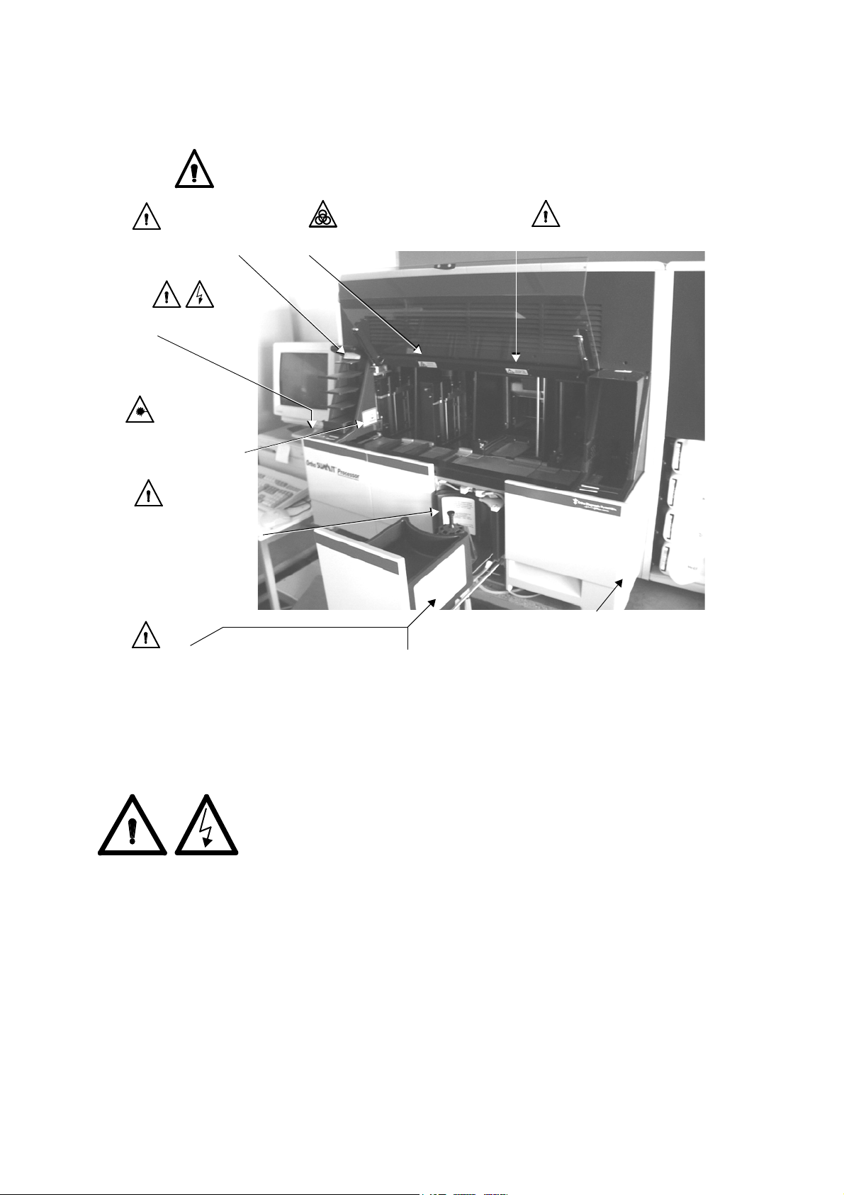
1.4.4.3 Hazards
Location of warning and attention labels and general location information:
Warning
Do not swap plates after loading.
Power Supply
(on left side) and
Instrument Serial Number
(on back side).
Warning
Laser Beam
Do not stare into beam
Class 2 Laser.
Warning
Do not overfill reagent container.
Close the reagent drawer gently
to prevent spillage.
Warning
Turn carousel untill it drops into locked
position. Ensure all plungers are pushed
down and caps are properly closed.
Warning
Biohazard (inside transparent cover).
Warning
Moving Parts (inside transparent cover).
Before removing the module,
decontaminate the instrument, unplug all
connectors and seal the fluid system as
described in the manual.
Pause
Instrument pause button.
P/N 610520/02 05/01
Figure 1.2 Warning Labels and general locations
Explanation of warning and attention labels
Power Connection:
Connect only to earth grounded outlet
115V~/...A 60Hz
230V~/...A 50Hz
1-19
Page 24

Microlab F.A.M.E. User Manual V2.0 —————————————————————————— ML F.A.M.E. Overview ——
Warning Symbols
General
Warning
Bio-Hazard
Danger
High Voltage
Danger
Laser
If the instrument becomes contaminated with liquids, it should be
cleaned in accordance with the maintenance procedures, see Reference Guide Section 15.1.6 on page 173.
Certain parts of the instrument are biohazardous. Observe and
carry out the maintenance procedures, see Reference Guide Section 15.1.6 on page 173 paying particular regard to cleaning and
decontamination.
Do not use disinfecting materials which contain hypochlorite (Javelle water, Chlorox) or bleaching fluids.
Failure to observe and carry out the maintenance procedures may
impair the reliability and correct functioning of the instrument.
Wear gloves when exchanging the sterile filter and handling the
venting tube as any liquid which is released is biohazardous.
Any surfaces on which liquid is spilled must be decontaminated.
1.4.4.4 Software Precautions
The ML F.A.M.E. Workstation should not be used for running any
other applications (programs) except those described in 1.3.2 en la
página 1-9.
The ML F.A.M.E. Workstation date and time must not be changed
while the instrument is running tests or while the user software is
running or being started up, otherwise trouble-free operation cannot be guaranteed.
The operating system (OS/2) and database (DB2/2) functions are
optimized to suit the instrument configuration. Changes to the
setup can impair the operational reliability and data security of the
system.
Only the ML F.A.M.E. software may be used to control the ML
F. A . M . E . .
1-20
When running the system 24 hours a day, shut down and restart
the system once a day in order to re-calibrate the washer, photometer, etc. and also carry out cold start maintenance.
P/N 610520/02 05/01
Page 25

Microlab F.A.M.E. User Manual V2.0 —————————————————————————— ML F.A.M.E. Overview ——
The ML F.A.M.E. operator is responsible for the security of communication between the ML F.A.M.E. and any host computer. The ML
F.A.M.E. system creates result files but does not provide the specific communication protocols to ensure reliable and safe transmission of result files.
P/N 610520/02 05/01
1-21
Page 26

Microlab F.A.M.E. User Manual V2.0 —————————————————————————— ML F.A.M.E. Overview ——
1-22
P/N 610520/02 05/01
Page 27

Microlab F.A.M.E. User Manual V2.0 ——————————————————————————————— Cook Book ——
Chapter
2 - 8 Cook Book
Cook Book Sections
2 - Cook Book Introduction............................................................25
3 - ML F.A.M.E. Methods ................................................................27
4 - Daily Work Routine....................................................................41
5 - Test Results & ML F.A.M.E. Traces............................................55
6 - Instrument Status ......................................................................63
7 - ML F.A.M.E. Verification.............................................................65
8 - ML F.A.M.E. Maintenance .........................................................69
P/N 610520/02 05/01
2-23
Page 28

Microlab F.A.M.E. User Manual V2.0 ——————————————————————————————— Cook Book ——
2-24
P/N 610520/02 05/01
Page 29

Microlab F.A.M.E. User Manual V2.0 ———————————————————— Cook Book - Cook Book Introduction ——
Chapter
2 Cook Book Introduction
The purpose of the cook book is to give a step-by-step guide to the
day-to-day operation of the ML F.A.M.E. and the ML F.A.M.E. software version 2.0.
Each section consists of an introduction explaining the basic principles being covered, then a step by step guide to each task in a
tabulated two column format.
r Column 1 - The Task.
r Column 2 - The Procedure.
Any additional information for the operator’s attention is displayed
in the left margin as either a “Note” or an “Attention”.
A certain amount of basic computer understanding will be
assumed throughout these examples and most will assume that a
valid ML F.A.M.E. operator with the necessary access rights is
logged in to the ML F.A.M.E. workstation.
In trying to avoid long-winded explanations and examples, common information, i.e. explanations of common fields, push-buttons,
etc., of a repetitive nature has been omitted (unless applicable) and
is explained in the Reference Guide section of this document set.
Special information, directly related to the task being explained
(but not a step in the procedure) like warnings and notes being
brought to the attention of the user are displayed in the left margin
of this document to avoid breaking the flow of the examples.
P/N 610520/02 05/01
2-25
Page 30

Microlab F.A.M.E. User Manual V2.0 ———————————————————— Cook Book - Cook Book Introduction ——
2-26
P/N 610520/02 05/01
Page 31

Microlab F.A.M.E. User Manual V2.0 ————————————————————— Cook Book - ML F.A.M.E. Methods ——
Chapter
3 ML F.A.M.E. Methods
Table of Contents
3.1 - Overview.................................................................................28
3.1.1 - Method Definition .............................................................28
3.1.2 - Documenting a Test Run ..................................................37
3.1.3 - Method Management .......................................................38
P/N 610520/02 05/01
3-27
Page 32

Microlab F.A.M.E. User Manual V2.0 ————————————————————— Cook Book - ML F.A.M.E. Methods ——
3.1 Overview
A method is a structured group of definitions, stored electronically,
which enables an Immunoassay test to be performed on the ML
F.A.M.E. and includes plate layout information, processing step
definitions and documentation criteria for the test.
For further information on methods see Reference Guide Section -
10.1 on page - 84.
3.1.1 Method Definition
The following section defines the creation of a method as
described in a Test Kit Manufacturer’s Package Insert. Even though
it is not generally possible to create or edit in any way, this is
explained to clarify the structure of the methods.
Example Information Required To Program A Method
NOTE
Only wash solutions that are
specified as suitable by the test
kits’ manufacturer should be
used.
NOTE
Plate dimensions are not nor-
mally included in the package
insert and must be measured by
hand with the vernier caliper.
This is to prevent possible spillage, contamination, or errors
during wash and dispense
steps. The dimensions shown
are given as an example only.
Method Name: Example ELISA.
Manufacturer: Example Company.
Parameter: Hepatitis B Antigen.
Tes t K i t: The Test Kit contains all necessary reagents
except wash and stop solution, which is
available separately. Note that the substrate
solution should be used within 60 mins of
preparation.
Ambient
Temperature
Conditions: 15 - 30°C
Plate
Dimensions : Plate Length: 127.5 mm
Plate Height: 14.5 mm
Well Diameter: 6.6 mm
Well Depth: 11.4 mm
Well Shape: Flat
Strip Direction: A - H
3-28
Assay
Procedure:
Sample Filling Direction: A - H
1 Dispense 50 ml of conjugate solution into
each well of the plate except the blank.
P/N 610520/02 05/01
Page 33

Microlab F.A.M.E. User Manual V2.0 ————————————————————— Cook Book - ML F.A.M.E. Methods ——
Example Information Required To Program A Method
2 Pipette controls and samples as follows:
- A1 Substrate Blank (BL)
- B1, C1 & D1 (100 ml) - Negative Control
(NC)
- E1 & F1 (100 ml) - Positive Control
(PC)
- G1 & H1 keep empty (##)
- Pipette all remaining wells with 100 ml of
the SAmples to be tested
3 SRAM (measuring filter - 450 nm) see
Reference Guide Section - 10.2.3.3 on page
- 95 for further information on this step.
4 Place the plate in the incubator as soon as
possible, max. 30 min after completion of
the sample distribution step.
5 Incubate at 37 +/- 1°C for 30 +/- 5 min.
6 Wash plate 5 times: completely aspirate the
liquid from all wells and fill the wells with
370 ml of wash solution. The washing
solution should be allowed to remain for 20
seconds in the wells before being removed.
(CONTINUED)
7 Dispense 200 ml of the substrate solution
into each well.
8 SRAM (measuring filter - 450 nm).
9 Incubate the plate at room temperature for
30 +/- 2 min.
10 Reidentify the plate.
11 Stop the reaction by adding 50 ml 2 mol/l
sulphuric acid to each well.
12 Shake the plate for 10 seconds.
13 Read the optical density at 492 nm, with 620
nm as the reference wavelength.
P/N 610520/02 05/01
3-29
Page 34

Microlab F.A.M.E. User Manual V2.0 ————————————————————— Cook Book - ML F.A.M.E. Methods ——
The following table defines, step by step, how to create this
method as per the above method programming information.
Table 3.1.1.1 - Method Definition Process
To... Do This...
Create a method .1) Select the New menu choice from the
Methods pull-down menu. The
Method - New dialog box is then
displayed. Enter the name “Example
ELISA”.
NOTE
The Barcode Mask (see Refer-
ence Guide Section - 10.2.1 on
page - 86) must be unique and
must correspond exactly to the
barcodes used on the plates.
For further information on Plate
hold time and Pipetting delay
see Reference Guide Section -
10.2.1 on page - 86.
ATTENTION
The plate dimensions specified in
the plate configuration must
correspond to dimensions of
the plate, otherwise
contamination, spillage or errors
may occur during wash and
dispense steps.
Method
identification
information
.2) The Method information dialog box
(see Reference Guide Section - 10.2.1
on page - 86) is displayed, enter the
Manufacturer:
Example Company
Parameter: Hepatitis B Antigen
Barcode Mask:
HB#######?????****
Plate Hold Time: 30 mins
Pipetting Delay: 5 mins
Read Access: 2
Write Access: 6
.3) Confirm the Method Information
dialog box definition by selecting the
OK push button.
Layout editor .4) The Layout editor allows the ML
F.A.M.E. operator to define what goes
where in the plate.
Plate
configuration
.5) From the Configuration menu select
the Set Plate Dimensions menu
choice.
.6) Enter the plate’s dimensions in the
appropriate entry fields.
Arranging sample
well types
.7) First select the filling direction from the
Configuration menu, either vertical
(A-H) or horizontal (1-12). A marker
on the menu shows which direction is
selected. For this example select A -
H.
3-30
.8) Next select the required Replica
Number from the Samples menu to
define the number of replicas of each
sample (a value of 1 gives 1 well per
sample. A value of 2 gives 2 wells per
sample, etc.). In this case a value of 1
is required.
P/N 610520/02 05/01
Page 35

Microlab F.A.M.E. User Manual V2.0 ————————————————————— Cook Book - ML F.A.M.E. Methods ——
Table 3.1.1.1 - Method Definition Process (CONTINUED)
To... Do This...
Defining control well
types
Deleting well types .11) Delete any well types that will not be
Assigning control
well types
.9) For this example the required well
types are Positive Control (PC),
Negative Control (NC), Samples (SA)
and Blank (BL). Except for Blank well
types, all the above are ML F.A.M.E.
software defaults.
.10) From the Edit menu select the Edit
Well Types menu choice.
Select the Insert push button. A new
line is created in the table.
Enter BL in the abbreviation entry
field, Blank in the Used as entry field
and an optional comment.
Confirm the definition with the OK
push button.
required for the test.
From the Edit menu select the Edit
Well Types menu choice.
Select the well types to be deleted
and select the Delete push button.
.12) Choose a well type from the Select
Well Type drop-down list.
NOTE
If there are any unused well types
in the layout, they must be
deleted.
Remember to rearrange the layout again if well types have
been deleted.
.13) The cursor icon will change from an
arrow to a Pencil (
edit mode, then select a well to
allocate its selected well type as per
the desired layout.
Completing the
layout
Checking the layout .15) Finally select the Check Layout menu
Test processing
editor
Prepare plate .17) This is carried out external to the ML
.14) Select the Arrange Samples menu
choice from the Samples menu to
automatically complete the plate
layout, assigning all remaining empty
wells as sample wells. This is always
the last action in laying out a plate.
choice from the File menu to
automatically check the plate layout
for errors.
.16) Activate the Test Processing Editor by
double clicking on its icon.
F.A.M.E. and the ML F.A.M.E. operator
only needs to define the approximate
time required to fill the plate with
samples (in this example 10 minutes).
!) indicating well
P/N 610520/02 05/01
3-31
Page 36

Microlab F.A.M.E. User Manual V2.0 ————————————————————— Cook Book - ML F.A.M.E. Methods ——
Table 3.1.1.1 - Method Definition Process (CONTINUED)
To... Do This...
NOTE
Sample and Reagent Addition
Monitoring is used to check dis-
pensing and can be used at any
time in a test run (for fur ther
information on the SRAM step
and additional functions see
Reference Guide Section -
10.2.3.3 on page - 95).
NOTE
For incubation times of 30 min-
utes and less, fast heating up is
recommended.
SRAM .18) From the Steps menu select the
Sample and Reagent Addition
Monitoring menu choice.
.19) In the displayed dialog box select a
Measuring Filter of 450 nm, an
optional Reference Measurement
Filter and range check criteria.
Incubate .20) From the Steps menu select the
Incubate menu choice.
.21) In the displayed dialog box select the
Temperature controlled incubation
radio button.
.22) Enter a temperature of 37°C (default
setting).
.23) An operating temperature tolerance
must be set defining the maximum
variation in temperature (between 1°C
and 5°C).
.24) Select the Fast option from the
Heating up drop-down list.
.25) Enter the required incubation and
tolerance times (in this example 30
minutes and 5 minutes).
NOTE
Global Fluids are designated by a
preceding asterisk (*) in their
name.
Wash .26) From the Steps menu select the
Wash menu choice.
.27) Select the Plate wash option.
.28) Before the wash step can be used a
wash solution must be defined.
Define global fluid .29) From the Test Processing Editor -
Wash dialog box select the Edit
Global push button, then in the
displayed dialog box select the New
push button. The Edit Global Fluid
dialog box is displayed.
.30) Enter the Wash Fluid name - OCD-01
- and a preparation time of 10 mins.
.31) Confirm this with the OK push button
and the new fluid will appear in the
display of the Edit Global Fluids dialog
box.
3-32
P/N 610520/02 05/01
Page 37

Microlab F.A.M.E. User Manual V2.0 ————————————————————— Cook Book - ML F.A.M.E. Methods ——
Table 3.1.1.1 - Method Definition Process (CONTINUED)
To... Do This...
.32) Return to the Test Processing Editor -
Wash dialog box by selecting the
Close push button.
NOTE
In this example, no wash options
are selected. To select a wash
option, select the Wash
Options... push button, additional wash options include
Continuous wash, Bottom
wash, Bottom sweep and
Pump power (see Reference
Guide Section - 10.2.3.3 on
page - 95).
Dispense .35) From the Steps menu select the
.33) Select the new wash solution from the
drop down list.
Enter the required wash/dispense
volume or select it from the dropdown list (In this example 370 ml) then
the Number of Cycles (5 in this
example), Soak Time (20 sec.) and
Aspiration Height (0.3 mm).
.34) To enter this step in the test process
definition select the OK push button.
Dispense menu choice.
NOTE
For method specific reagents, it is
recommended to include the
method name as part of the
reagent name to make barcode
assignment easier during a run.
Define method
specific fluid
.36) Before the Dispense step can be used
a reagent must be defined.
.37) The reagent is specific to this method
(i.e. not global), select the Edit
Method specific push button. The
Edit Method Specific Fluids dialog box
is displayed.
.38) Select the New push button.
The Edit Method Specific Fluid dialog
box will appear. Enter the name
“SUBSTRATE” in the Name entry field
then the time it will take to prepare the
substrate solution.
.39) In this case the solution is unstable so
select the Reagent Is Unstable check
box and enter the stability time (in this
case 60 minutes).
.40) Confirm this with the OK push button
and the new fluid will appear in the
display of the Edit Method Specific
Fluid dialog box.
.41) Select the Close push button and the
ML F.A.M.E. software returns to the
Dispense dialog box.
P/N 610520/02 05/01
3-33
Page 38

Microlab F.A.M.E. User Manual V2.0 ————————————————————— Cook Book - ML F.A.M.E. Methods ——
Table 3.1.1.1 - Method Definition Process (CONTINUED)
To... Do This...
.42) Select “SUBSTRATE” from the Reagent
name drop-down list and a dispense
volume of 200 ml from the Volume
drop-down list.
Select a Slow aspirate speed from the
drop-down list.
Select a Slow dispense speed from
the drop-down list.
.43) To enter this step in the test process
definition select the OK push button.
SRAM .44) See - Step 3, Item Number 18)
Incubate .45) From the Steps menu select the
Incubate menu choice.
.46) In the displayed dialog box select the
Ambient incubation radio button.
.47) Enter the lower and upper
temperature limits for ambient
incubation given in the package insert
(in this case 15 and 30°C).
.48) Enter the required Incubation and
tolerance times (in this example 30
minutes and 2 minutes) and select the
OK push button.
Re-identify .49) Select the Re-identify menu choice
from the Steps menu to check that the
plate barcode matches the one read
at the start of the run.
Dispense .50) From the Steps menu select the
Dispense menu choice.
.51) Before the dispense step can be used
a reagent must be defined.
This is a global reagent since it is not
specific to any one method.
.52) Select Edit Global... The Edit Global
Fluid dialog box is displayed.
3-34
.53) Select the New push button.
The Edit Global Fluid dialog box will
appear.
P/N 610520/02 05/01
Page 39

Microlab F.A.M.E. User Manual V2.0 ————————————————————— Cook Book - ML F.A.M.E. Methods ——
Table 3.1.1.1 - Method Definition Process (CONTINUED)
To... Do This...
.54) Enter the name “2 MOL/L H2SO4” in the
Name entry field then the time it will
take to prepare (10 mins), select the
OK push button to confirm selection.
Then select the Close push button to
return to the Dispense dialog box.
.55) Select “
2 MOL/L H2SO4” from the
Reagent name drop-down list and a
dispense volume of 50 ml from the
Volume drop-down list.
.56) Select the Well push button to define
into which well types to dispense. The
Select Wells dialog box will appear.
.57) Choose the well types to dispense by
selecting them from the Well Types
drop down list (in this example all well
types should be selected). The
selected wells will appear highlighted
in the plate layout.
.58) Select OK. The message “All types ”
should appear in the Wells field of the
Dispense dialog box.
.59) Select a slow aspiration speed from
the drop-down list.
Select a slow dispense speed from
the drop-down list.
.60) To enter this step in the test
processing definition select the OK
push button.
NOTE
When specifying a Photometer
Filter for an assay it is important
to check that this Photometer
Filter is installed.
P/N 610520/02 05/01
Mix .61) From the Steps menu select the Mix
menu choice.
.62) Select the medium mix intensity.
.63) Select a mix time of 10 seconds, then
click on the OK push button.
Read .64) Select the Read menu choice from
the Steps menu.
.65) Select the 492 nm measuring filter
from the drop-down list.
3-35
Page 40

Microlab F.A.M.E. User Manual V2.0 ————————————————————— Cook Book - ML F.A.M.E. Methods ——
Table 3.1.1.1 - Method Definition Process (CONTINUED)
To... Do This...
.66) The method also requires a reference
measurement. Select the Reference
measurement check box and select
the 620 nm reference filter. Then
select the OK push button.
Check method .67) Once the processing definition is
completed the method must be
checked for errors in the test
processing definition.
.68) Select Check Layout And
Processing Definition... from the File
menu to check the layout and test
NOTE
A method that returns warnings
when checked may still be run
while a method returning errors
will prevent the method being
run.
processing definition.
.69) If errors were found in the layout or
processing definition the ML F.A.M.E.
operator will be prompted as to the
type of error and its location.
.70) Once these errors have been
corrected re-check the method until
no errors are returned.
Defining the first
processing step
.71) From the Edit menu select the Select
First Processing Step menu choice.
A dialog box will be displayed
allowing the ML F.A.M.E. operator to
select the step number that will be
addressed first in the run process
which defines the end of the plate
hold time.
Save method .72) From the File menu select the Save
menu choice and the method is saved
in the data base under the name
entered in the beginning of the
definition in this case Example ELISA.
This completes the test processing (method) definition.
3-36
P/N 610520/02 05/01
Page 41

Microlab F.A.M.E. User Manual V2.0 ————————————————————— Cook Book - ML F.A.M.E. Methods ——
3.1.2 Documenting a Test Run
Information generated by a test run can be handled in a number of
ways. These are called documentation jobs. Documentation jobs
are method specific and can be defined in various ways including
or excluding different information. These are called documentation
formats and are global, i.e. they can be used by multiple methods
by being included in the method specific documentation job.
Table 3.1.2.1 - Documentation Jobs
To... Do This...
Working with
documentation
formats
Create a new or
change an existing
documentation
format
Assigning a
documentation
format to a doc.
job and then a
method
.1) From the Methods menu select the Edit
Globals menu choice then the Formats
sub-menu choice.
.2) The Documentation Formats dialog
box is displayed allowing the ML
F.A.M.E. operator to create new
documentation formats and change or
delete existing ones.
.3) The Documentation Formats dialog
box allows the ML F.A.M.E. operator to
enter a name and comment for the
documentation format then specify the
various information to be contained in
the documentation job, including trace
information, OD values and plate
information.
.4) From the Methods menu select the Edit
menu choice then the Documentation
sub-menu choice.
P/N 610520/02 05/01
.5) A dialog box is displayed listing all
documentation jobs available for use.
This includes the documentation format
used and the destination device of that
information.
New .6) Select the New push button and in the
dialog box, a list of documentation
formats and possible device
destinations is displayed.
.7) Select the desired options and the Save
push button and the new
documentation job is displayed in the
Documentation Job dialog box.
3-37
Page 42

Microlab F.A.M.E. User Manual V2.0 ————————————————————— Cook Book - ML F.A.M.E. Methods ——
Table 3.1.2.1 - Documentation Jobs (CONTINUED)
To... Do This...
Change .8) The Change push button allows the ML
F.A.M.E. operator to edit an existing
Documentation Job’s properties (see
New above).
Delete .9) To delete an existing Documentation
Job select it then select the Delete push
button.
Start
.10) With this option selected the test’s
documentation by
user
information must be released manually
by the ML F.A.M.E. operator as opposed
to automatically at the end of the run
(see Reference Guide Section - 12.2.1
on page - 133).
3.1.3 Method Management
NOTE
When a copy is made of a
method the new method will not
have a barcode mask as no two
methods can use the same barcode mask. It is then necessary
to open the method, define the
new barcode mask then check
the full method definition. For
information on barcode mask
see Reference Guide Section -
10.2.1 on page - 86.
NOTE
An open method’s name will not
appear in the selection dialog
box when Copy, Rename or
Delete are selected. A method
cannot be deleted if test results
for that method exist on the system.
In general, it is only possible for ML F.A.M.E. operators to use the
“Save As, Copy, Rename, Delete, Backup & Restore Methods”
functions. The following table explains these procedures.
As most of the dialog boxes for these procedures are identical the
process will be explained once in entirety then again for each further command using reference to the common elements.
Table 3.1.3.1 - Save As, Copy, Rename, Delete, Backup,
Restore and Print a Method.
To... Do This...
Save as... .1) From the Methods menu in the main ML
F.A.M . E . w in dow s e le ct the Manage
sub-menu then the Save as... menu
choice.
.2) A dialog box is displayed allowing the
ML F.A.M.E. operator to enter a new
name for the method.
Copy... .3) If a method is open for editing the ML
F.A.M.E. operator is prompted for the
new method name. However, when no
method is open, a dialog box is
displayed listing all methods available to
the ML F.A.M.E. operator on the ML
F.A.M.E. database allowing the selection
of the method to be copied and an entry
field for its new name.
3-38
P/N 610520/02 05/01
Page 43

Microlab F.A.M.E. User Manual V2.0 ————————————————————— Cook Book - ML F.A.M.E. Methods ——
Table 3.1.3.1 - Save As, Copy, Rename, Delete, Backup,
Restore and Print a Method. (CONTINUED)
To... Do This...
Rename... .4) Select the method from the list in the
displayed dialog box and enter the new
name.
Delete... .5) To delete a method select the method
from the displayed list and use the
delete push button. The method will be
removed from the ML F.A.M.E.
database.
Backup... .6) To backup an open method the ML
F.A.M.E. operator must only enter a path
to the desired directory, however if no
method is open the ML F.A.M.E.
operator is asked to first select a
method.
NOTE
The default back-up path for a
method is defined in the Software
Presettings dialog box (see Reference Guide Section - 13.2.5 on
page - 142)
Restore... .7) To restore a backed-up method the ML
F.A.M.E. operator will be prompted for
the backup path. A list of all methods
that have been backed-up will then be
displayed for selection.
Print... .8) With a method open for editing the print
command prints that method, however
with no method open the ML F.A.M.E.
operator is prompted to select the
method to be printed from a dialog box
listing all methods available to that ML
F.A.M . E . o pe rat or.
P/N 610520/02 05/01
3-39
Page 44

Microlab F.A.M.E. User Manual V2.0 ————————————————————— Cook Book - ML F.A.M.E. Methods ——
3-40
P/N 610520/02 05/01
Page 45

Microlab F.A.M.E. User Manual V2.0 —————————————————————— Cook Book - Daily Work Routine ——
Chapter
4 Daily Work Routine
4.1 Concept of the Daily Work Routine
Below is a flow chart giving the logical flow of the daily work routine
for the ML F.A.M.E.. Each of these steps are explained in greater
detail in the following pages.
Concept of the
Daily Work Routine
- Start -
OSP System
Start-Up
Perform
Maintenance
Continued
Prepare, Verify &
Start Work List
Processing
Load all Fluids
Define or Select
Stack Type(s)
Define or Select
Work List
Schedule
Work List
Continued
OSP Processes
all Plates
Perform
Maintenance
OSP System
Shut-Down
Concept of the
Daily Work Routine
- Finish -
P/N 610520/02 05/01
4-41
Page 46

Microlab F.A.M.E. User Manual V2.0 —————————————————————— Cook Book - Daily Work Routine ——
4.1.1 System Start-Up and Shut-Down
This section details the start-up procedure and outlines the tasks
necessary before a test run can be started.
Table 4.2 - Starting-up and Shutting-down the ML F.A.M.E.
To... Do This...
ATTENTION
Do not switch off instrument,
open drawers or transparent
cover, touch load button or any
moving parts during
initialization.
ATTENTION
No other programs or
applications should be started
while the ML F.A.M.E.
software is running.
Start up the ML
F. A . M . E .
.1) Turn on ML F.A.M.E. workstation power
supply.
.2) Turn on ML F.A.M.E. instrument power
supply.
.3) Enter ML F.A.M.E. operator name.
.4) Enter password.
.5) The instrument is then initialized to
check whether the instrument and ML
F.A.M.E. software are in an operable
condition.
.6) The ML F.A.M.E. software will then run a
maintenance status check to establish
the maintenance routines required.
.7) The ML F.A.M.E. operator will be
prompted to run cold start maintenance
if:
a) The instrument has been initialized
for the first time that day.
b) more than 24 hours have passed
since the last cold start
maintenance was run.
ATTENTION
It is very important that the ML
F. A . M . E . operator waits until
prompted by the ML F.A.M.E.
workstation before turning off
the power supply. This is due to
the closing of the ML F.A.M.E.
database and misuse can result
in ML F.A.M.E. database
corruption.
4-42
Shut down the ML
F. A . M . E .
.8) A check is made to ascertain when the
ML F.A.M.E. had its last verification
check. See chapter 7 for further
information on verification.
.9) Exit all windows and editors.
.10) From the File Menu in the main ML
F.A.M . E . w in dow s e le ct the Exit menu
choice.
.11) The ML F.A.M.E. software will then run a
maintenance status check to establish
the maintenance routines required.
P/N 610520/02 05/01
Page 47

Microlab F.A.M.E. User Manual V2.0 —————————————————————— Cook Book - Daily Work Routine ——
4.2.1 Stack Types
Below is a step-by-step guide to working with stack types. For a
general description of and further technical information on stack
types, see Reference Guide Section - 11.1.1 on page - 106.
Table 4.1.2.1 - Define a New Stack Type
To... Do This...
NOTE
The List of Stack types... push
button displays a list of all existing stack types.
The order in which methods are
placed in a stack type does not
define the order in which plates
are processed in a run. The
scheduler decides the optimum
processing order.
Define a new stack
Name the stack
Add methods to
the stack type
Remove methods
from the stack type
Save and exit .5) When all required methods are in the
.1) From the Main ML F.A.M.E. window
type
type
select the Work menu then the Stack
Typ e menu choice then the New sub-
menu choice.
.2) The New Stack Type dialog box is then
displayed, enter the desired (unique)
name for the new stack type (i.e.
Example Stack Type).
.3) From the Method list box select the
method to be added to the stack type
(i.e. Example ELISA), then click the Add
push button. The selected method will
be placed in the Stack Type list box.
Continue this process until the desired
stack type is achieved.
.4) To remove a method from the stack
type, select the method name in the
Stack Type list box and click on the
Remove push button.
stack type contents list box click the
Save/Next push button and then either
exit the dialog box using the Cancel
push button or repeat the above
process to define another stack type.
P/N 610520/02 05/01
4-43
Page 48

Microlab F.A.M.E. User Manual V2.0 —————————————————————— Cook Book - Daily Work Routine ——
Table 4.1.2.2 - Edit a Stack Type
To... Do This...
Edit a stack type .1) From the Main ML F.A.M.E. window
select the Work menu then the Stack
Typ e menu choice then the Edit submenu choice.
.2) The Stack Type Select dialog box is
then displayed, select the desired stack
type from the list box.
.3) Follow the procedures in the above
table to edit and save the stack type.
Table 4.1.2.3 - Print or Delete a Stack Type
To... Do This...
Print or delete a
stack type
4.1.3 Kit Lot Editor
The Kit Lot Editor is only available if the Kit Lot Documentation
option was selected during the installation procedure. When using
the Kit Lot Editor the defined kit lot will be documented and any kit
lot information provided in the plate barcode or in the barcode file
will be ignored.
If this installation option is not selected then the ML F.A.M.E. software will perform an active kit lot check and compare the loaded kit
lot elements with the defined elements.
.1) From the Main ML F.A.M.E. window
select the Work menu then the Stack
Typ e menu choice then the Delete or
Print sub-menu choice.
.2) The Stack Type Delete or Print dialog
box is then displayed, select the desired
stack type from the list box.
.3) Click the Delete or Print push button
and the selected stack type is erased
from the ML F.A.M.E. database or
printed to the OS/2 default printer.
4-44
Table 4.1.3.1 - Working with the Kit Lot Editor
To... Do This...
Define a new kit lot .1) From the Main ML F.A.M.E. window
select the Work menu then the Kit Lot
Editor menu choice.
P/N 610520/02 05/01
Page 49

Microlab F.A.M.E. User Manual V2.0 —————————————————————— Cook Book - Daily Work Routine ——
Table 4.1.3.1 - Working with the Kit Lot Editor
To... Do This...
.2) The Kit Lot Editor is displayed and lists
all currently stored kit lot data on the
system in the path defined in the
software presettings.
Define a kit lot for a
method
Define the kit lot of
a global fluid
4.1.4 Work Lists
.3) From the Edit menu select the Insert
Kit Lot menu choice.
.4) Select a method from the pull-down list
and then select the OK push button.
.5) A dialog box is displayed where the new
kit lot is assigned to an existing method,
its expiration date and components
(with the component lot numbers) can
be defined.
.6) From the Edit menu select the Insert
Global Fluid menu choice.
.7) Here the ML F.A.M.E. operator may
select a global fluid name, its expiration
date, whether it is a single or dual
component and the either a single
component lot number or two lot
numbers if it is a dual component.
Below is a step-by-step guide to working with work lists (for further
information on work lists see Reference Guide Section - 11.1.1 on
page - 106).
For the purposes of these examples it is assumed that all method
data is correct and kit lots exist and are date validated.
Table 4.1.4.1 - Define a New Work List
To... Do This...
Define a new work
Include a stack in
a work list
.1) From the Main ML F.A.M.E. window
list
select the Work menu then the Work
List Manager menu choice.
.2) The Work List Manager window is then
displayed.
.3) From the Edit menu select the Insert
Stack Type menu choice.
.4) A dialog box is displayed listing all
available stack types.
P/N 610520/02 05/01
4-45
Page 50

Microlab F.A.M.E. User Manual V2.0 —————————————————————— Cook Book - Daily Work Routine ——
Table 4.1.4.1 - Define a New Work List (CONTINUED)
To... Do This...
NOTE
Each individual Method’s state is
checked to ensure it is error free
and that the corresponding Kit
Lot is correct for the method
and the expiry date has not been
reached.
.5) Select the required stack type name (i.e.
Example Stack Type) from the list and
click on the Insert push button.
.6) After a moment the stack will appear in
the Work List Manager window. For
further information on the contents of
the Work List Manager window, see
Reference Guide Section - 11.3 on page
- 109.
.7) To insert a stack in-between two stacks,
select the lower of the two and use the
Insert menu choice from the Edit menu.
The new stack will be placed above the
selected stack.
NOTE
It is not possible to perform any
actions on a work list (or individual stack in the list) that has
a status of planned or running.
In order to edit the properties of
a stack the planned work list
must be un-scheduled (see
Table 4.1.4.3, “Scheduling and
Un-scheduling a Work List,” on
page 47). Therefore, running
work lists and their stack types
cannot be edited.
NOTE
The ML F.A.M.E. software
allows two way of defining the
earliest starting time for a
stacks processing: either time
of day (i.e. the ML F.A.M.E.
operator defines an actual time
for the start) or as an offset to
the previous stacks start time.
When the first stack uses the
offset time the start time is offset from the time the stack is
planned.
Remove a stack
from a
work list
.8) Select the stack to be removed from the
work list and either select the Delete
menu choice from the Edit menu or
press the keyboard Del key.
.9) Repeat this process until the desired
work list arrangement is achieved. Then
select the Close push button to return
to the Work List Manager window.
Define the earliest
start time
.10) Select the stack type name and then
from the Edit menu the Set Earliest
Start Time menu choice.
.11) Set the Time of Day or the Delay to the
Previous Stack.
Change the kit lot .12) By selecting an individual method in a
stack and the Change Kit Lot menu
choice from the Edit menu a dialog box
is displayed listing all kit lots available
for use with this method (also see Table
4.1.3.1 - Working with the Kit Lot Editor)
.13) Select the required kit lot and click the
OK push button. All methods of the type
selected will now use the new kit lot.
Print the work list .14) From the File menu select the Print
menu choice, the work list data will be
printed on the default OS/2 printer.
4-46
P/N 610520/02 05/01
Page 51

Microlab F.A.M.E. User Manual V2.0 —————————————————————— Cook Book - Daily Work Routine ——
Table 4.1.4.1 - Define a New Work List (CONTINUED)
To... Do This...
Save the work list .15) From the File menu select the Save As
menu choice, a dialog box is displayed
where the (unique) work list name is
entered (i.e. Example Work List).
Select the Save push button and the
work list is stored in the ML F.A.M.E.
database.
There is also a Display List push button
that allows the ML F.A.M.E. operator to
view a list of all, available, defined work
lists.
Table 4.1.4.2 - Edit a Work List
To... Do This...
Edit a work list .1) To edit an existing work list select the
Open menu choice from the File menu,
a dialog box is displayed listing all
available work lists.
.2) Select the desired work list and follow
the steps in the above table to either
add new stacks or delete existing ones.
Once a work list has been created it is then possible to create a
schedule of processing events as follows:
Table 4.1.4.3 - Scheduling and Un-scheduling a Work List
To... Do This...
Schedule a work
list (creating a
plan)
.1) To schedule the running of the open
work list select the Schedule menu
choice from the Actions menu in the
Work List Manager window.
.2) A progress indicator is displayed
indicating the percentage of the work
list scheduling completed.
P/N 610520/02 05/01
.3) When scheduling is completed the Plan
window is displayed. For further
information on the contents of the Plan
window see Reference Guide Section -
11.4 on page - 112.
4-47
Page 52

Microlab F.A.M.E. User Manual V2.0 —————————————————————— Cook Book - Daily Work Routine ——
Table 4.1.4.3 - Scheduling and Un-scheduling a Work List
To... Do This...
Work list status .4) When a work list has been successfully
scheduled the stack and individual
methods status will change from Not
Planned to Planned. All time lines
defined for the stacks are now active
and no further options can be defined
NOTE
Un-scheduling is a sequential
process, i.e. it is not possible to
un-schedule an individual stack
positioned in the middle of a
work list, selecting an individual
stack like this to un-schedule
will un-schedule the selected
stack and all following stacks in
the work list.
Un-schedule a
planned work list.
for this work list.
.5) Once a work list has been scheduled
and the ML F.A.M.E. software has
switched focus to the Plan window,
select the Work List menu choice from
the View menu (or use the F7 key) to
change the focus back to the Work List
Manager.
.6) Select the required stack (see Note) and
then from the Actions menu the Un-
schedule menu choice.
4-48
P/N 610520/02 05/01
Page 53

Microlab F.A.M.E. User Manual V2.0 —————————————————————— Cook Book - Daily Work Routine ——
4.1.5 Executing and Aborting a Run
After successfully scheduling a work list the Plan window is displayed (for further information on the Plan Window and its contents see Reference Guide Section - 11.4 on page - 112).
At this stage the ML F.A.M.E. operator should load all stable fluids,
please see section section 4.1.6 "Fluids" for a step-by-step guide to
working with fluids.
Table 4.1.5.1 - Starting a Run
To... Do This...
Start a run .1) From the Actions menu select the Start
Run menu option.
.2) The work list will now start processing
using the ML F.A.M.E. software defined
schedule.
NOTE
This option is only available if the
Plate Access On installation
option was selected.
ATTENTION
Selecting Retry or Search in path
must be carried out within two
minutes.
If any samples must be
excluded or included this must
be done prior to the first
aspirate, wash or SRAM step. If
there is insufficient time for this,
it is possible to add an ambient
incubation step.
Well barcodes can be entered
until before the start of
documentation.
ML F.A.M.E.
operator actions
Edit plate barcode
information
.3) The ML F.A.M.E. operator will be
prompted when action is required.
.4) Prepare plate(s):
The ML F.A.M.E. operator is prompted
to start the plate preparation given the
time specified in the prepared plate step
of the method definition.
.5) Load stack:
The ML F.A.M.E. operator is prompted
to load the appropriate stack then press
the instrument’s Load button.
.6) When a plate is loaded a search is
made to find the plate’s barcode data. If
this search can not find any information
the Pipetting Information Error dialog
box is displayed. By selecting Retry or
Search In Path another search is made
to find the pipetting information. With in
this dialog box it is then possible to
select the Edit Plate push button
displaying the Edit Plate dialog box.
.7) Here it is possible to include or exclude
samples and to edit a wells barcode
.8) Load Unstable Fluid(s):
Table 4.1.6.2, “Assigning Fluids in the
Plan Window,” on page 52.
P/N 610520/02 05/01
4-49
Page 54

Microlab F.A.M.E. User Manual V2.0 —————————————————————— Cook Book - Daily Work Routine ——
Table 4.1.5.1 - Starting a Run (CONTINUED)
To... Do This...
Abort a test/run .9) To abort an individual test or an entire
run the ML F.A.M.E. operator must
switch to the Work List Manager, use
the Work List menu choice from the
NOTE
Individual test can only be
aborted when the plate has
actually been loaded onto the
instrument.
Aborted tests will appear grey in
the Plan window.
All aborted plates will be transported to the exit module.
View menu or the F7 keyboard key.
.10) To abort an individual test select the test
and from the Abort menu use the
Selected Test menu choice, confirm the
action and the test is removed from the
schedule.
.11) The entire run can be aborted at any
time by following the above procedure
but selecting the Entire Run menu
choice.
4.1.6 Fluids
ATTENTION
It is important that the ML
F. A . M . E . operator ensures that
the correct fluids are placed in
the correct, labeled, container.
NOTE
Please consult with the manufac-
turer of stable fluids to ascertain
the exact stability status of their
fluids.
NOTE
It is important that the ML
F. A . M . E . operator check each
barcode while placing it on any
ML F.A.M.E. part to ensure it
is in a serviceable condition.
Fluid Loading
It is highly recommended that stable fluids which have a close
loading time, i.e. are the first fluids to be loaded, be loaded
together and assigned with a location and barcode prior to starting
a run. This will reduce the amount of time-critical work for the ML
F.A.M.E. operator during the run and will limit possible problems
caused by delays. The procedure for this is explained below in the
Assignment Editor section (Table 4.1.6.1, “Assignment Editor,” on
page 51).
While stable fluids are loaded before starting the run, unstable fluids must be loaded when the ML F.A.M.E. software requests them.
While unneeded fluids may be removed from the ML F.A.M.E. when
prompted by the ML F.A.M.E. software, this may not be done if a
dispensing step is scheduled for the next 5 minutes.
For further information on fluids see Reference Guide Section -
11.5 on page - 116.
NOTE
To avoid possible errors during a
run due to incorrect loading of
fluids, please label all fluid containers and storage containers.
4-50
P/N 610520/02 05/01
Page 55

Microlab F.A.M.E. User Manual V2.0 —————————————————————— Cook Book - Daily Work Routine ——
Fluid Assignment
Two procedures are possible for assigning fluids:
r The Assignment Editor (Stable Fluids) - allows the indepen-
dent assignment of fluids and their barcodes. Not available
while the Work List Manager is active.
Table 4.1.6.1 - Assignment Editor
To... Do This...
Insert a fluid .1) Open the Assignment Editor using the
Assignment Editor menu choice from
the Work menu in the main ML F.A.M.E.
window.
.2) From the Edit menu select the Insert
Fluid push button (or use the Insert key
on the keyboard) the Insert Fluid dialog
box is displayed.
.3) Two selection fields are displayed:
a) Method - lists all methods currently
available on the ML F.A.M.E.
database.
b) Fluid - lists all fluids available for
the selected method. The
method list indicates global fluids.
Select global fluids .4) To assign a global fluid select the
the Methods list box. Then from the list
of fluids displayed in the Fluids list box
select the desired fluid name then the
OK push button.
Select method-
specific Fluids
Assign the fluid .6) After the above steps the Assign dialog
.5) Select the method from the Method list,
any method specific fluids will be
displayed in the Fluid list. Select the
desired fluid and click the OK push
button.
box is displayed. Here the ML F.A.M.E.
operator must select the module where
the fluid is stored and dispensed from.
The container barcode information is
entered in the Assign Container
Barcode entry field.
*
in the
in
*
P/N 610520/02 05/01
Exiting the
assignment editor
.7) Select the Add push button. The fluid is
now assigned and ready for loading.
.8) When all desired fluids have been
assigned select the Close menu choice
from the File menu.
The fluid will be displayed in the
Assignment Editor window with the
specified information.
4-51
Page 56

Microlab F.A.M.E. User Manual V2.0 —————————————————————— Cook Book - Daily Work Routine ——
r After Scheduling (Unstable Fluids) - After a successful work
list scheduling the data defined in the Assignment Editor can
be overruled in the Plan window.
For further information on the contents of the Plan Window see
Reference Guide Section - 11.4 on page - 112.
Table 4.1.6.2 - Assigning Fluids in the Plan Window
To... Do This...
Select a fluid .1) Select the desired fluid in the Fluid
column of the Plan window.
.2) From the Actions menu select the
Assign Fluids menu choice or use the
NOTE
When the Load Fluid Container
dialog box is displayed, the first
column of which will indicate
whether the fluid has been verified. A marker, i.e. >, beside the
fluid entry means the fluid is
verified.
Barcode entry .3) The Assign Fluids dialog box is
Fluid verification .4) When the component lot number has
F4 keyboard key.
displayed. Then enter the container
barcode.
been entered (either using the barcode
scanner or manually using double blind
entry) and is correct, select the OK push
button. The fluid is now assigned and
ready for loading.
The normal procedure for fluid barcode assignment is by manual
entry of the barcode.
4.1.7 Barcode Scanner or Double-Blind Entry
Under certain circumstances the ML F. A .M . E . op e rat o r mu s t us e
the hand- held barcode scanner or double-blind entry procedure.
These circumstances include:
r Plate barcode not readable
r To verify a component lot number
r Correlate wash fluid
Table 4.1.7.1 - Double-Blind Entry
To... Do This...
Manually enter
barcode
information
.1) When required by the ML F.A.M.E.
software or selected by the ML F.A.M.E.
operator a dialog box is displayed
where barcode correlation is required.
4-52
P/N 610520/02 05/01
Page 57

Microlab F.A.M.E. User Manual V2.0 —————————————————————— Cook Book - Daily Work Routine ——
Table 4.1.7.1 - Double-Blind Entry
To... Do This...
.2) The ML F.A.M.E. operator must enter the
required barcode in the entry field via
the keyboard.
.3) When entered press the Ta b keyboard
key. The entered barcode will disappear.
.4) Enter the barcode again and press the
Tab key, the ML F.A.M.E. software will
check that the two entered barcodes are
identical. If so, the barcode correlation
is complete.
P/N 610520/02 05/01
4-53
Page 58

Microlab F.A.M.E. User Manual V2.0 —————————————————————— Cook Book - Daily Work Routine ——
4-54
P/N 610520/02 05/01
Page 59

Microlab F.A.M.E. User Manual V2.0 ——————————————— Cook Book - Test Results & ML F.A.M.E. Traces ——
Chapter
5 Test Results & ML F.A.M.E.
Traces
Table of Contents
5.1 - Test Results - Overview ..........................................................56
5.1.1 - The Test Results Window .................................................56
5.1.2 - The Test Result Report Dialog Box...................................58
5.2 - ML F.A.M.E. Traces - Overview ..............................................59
5.2.1 - The Trace Window............................................................60
P/N 610520/02 05/01
5-55
Page 60

Microlab F.A.M.E. User Manual V2.0 ——————————————— Cook Book - Test Results & ML F.A.M.E. Traces ——
5.1 Test Results - Overview
Once a test has been processed by the system, all resulting data
can be accessed from the Test Results Window.
5.1.1 The Test Results Window
After the processing of a test, whether successfully completed or
not, the results are stored on the ML F.A.M.E. database. The following tables give a step-by-step guide to working with these results.
Table 5.1.1.1 - Test Results Window - Procedures
To... Do This...
NOTE
A user needs the necessary
access rights to delete data.
Ensure that any tests to be
deleted have been documented.
Tests deleted from the ML
F. A . M . E . database cannot be
recovered.
Open the test
results window
Select viewing
options
Refresh the
display
Delete tests .6) There are three ways to delete tests
Delete a Single
.1) From the Results menu in the Main ML
F.A.M.E. window select the Test Results
menu choice.
.2) The Test Results window is displayed
listing the available test results stored
on the ML F.A.M.E. database.
.3) From the View menu select the List
Tests by Run Status menu choice.
.4) In the displayed dialog box, two check
boxes allow the ML F.A.M.E. operator to
select:
a) Processed - when checked will
display all tests with the run status
‘Processed’.
b) Documented - when checked will
display all tests with the run status
‘Documented’.
.5) To update the Test Results window,
either select the Refresh Now menu
choice from the View menu or use the
F5 keyboard key.
from the ML F.A.M.E. database. Each is
explained in the following section.
.7) To delete an individual test from the ML
Tes t
F.A.M.E. database, select the desired
test, then from the Te st s menu select
the Delete Selected Test(s) menu
choice.
5-56
.8) Confirm this action and the test will be
erased.
P/N 610520/02 05/01
Page 61

Microlab F.A.M.E. User Manual V2.0 ——————————————— Cook Book - Test Results & ML F.A.M.E. Traces ——
Table 5.1.1.1 - Test Results Window - Procedures (CONTINUED)
To... Do This...
Deleting multiple
tests
Enable multiple
test Selection
Delete tests by
criteria
.9) To delete multiple tests it is first
necessary to enable multiple test
selection.
.10) Select the Enable Multiple Test
Selection menu choice from the Te s ts
menu.
.11) It is now possible to select more than
one test at a time. To deselect a
selected test just click on the test.
.12) Select the desired tests to be deleted
then the Delete Selected Test(s) menu
choice.
.13) Confirm this action and the selected
tests will be erased.
.14) From the Te s t s menu select the Delete
Test by Criteria menu choice.
.15) Three radio button options are available
in the displayed dialog box.
a) All Existing Tests - this will delete
all test result data from the ML
F.A.M.E. database.
b) Documented Tests Only - this will
delete all tests whose
documentation has been released.
c) Aborted Tests Only - this will
delete all tests whose error status is
marked as aborted (see Reference
Guide Section - 12.1.1 on page -
131).
P/N 610520/02 05/01
Batch
documentation
.16) With the multiple test selection option
active, select the tests to be
documented.
.17) From the Te s t s menu select the
Documentation Tests Batch menu
choice.
.18) A dialog box will display the currently
available documentation format options
(See Cook Book page - 37) and
destination devices.
.19) Select the desired options and then the
Document push button. All defined
criteria will be followed for the selected
tests.
5-57
Page 62

Microlab F.A.M.E. User Manual V2.0 ——————————————— Cook Book - Test Results & ML F.A.M.E. Traces ——
5.1.2 The Test Result Report Dialog Box
Table 5.1.2.1 - Test Result Reports
To... Do This...
NOTE
Once a well has been excluded it
is not possible to re-include the
well. The ML F.A.M.E. opera-
tor who excluded the well and
the time and date of exclusion
are noted in the trace file.
View a test result’s
report
View an
individual well’s
details
Exclude a well .5) From the Well Details dialog box select
Attach a message
to a well
.1) From the displayed list select the
required test’s results line.
.2) Then from the Te st s menu select the
Show Test Results Report menu
choice or double click with the pointer
placed over the required line.
.3) The Test Results Report dialog box is
displayed giving detailed information
about the selected test (see Reference
Guide Section - 12.1 on page - 130).
.4) Select the desired well from the
graphical display then select the Well
Details push button. The Well Details
dialog box gives full well details.
the Exclude Well push button.
.6) From the Well Details dialog box select
the Insert Well Comment push button.
.7) A dialog box is displayed where the ML
F.A.M.E. operator can attach a short
message to the selected well.
NOTE
It is only possible to document
tests with the status Processed
or documented.
View well data in a
tabulated format
View the test
trace
Manually release
the documentation
for the test
.8) Select the Table View push button in
the Test Results Report dialog box.
.9) The Test Results Report - Table View
dialog box is displayed.
.10) The Sort push button allows the user to
specify the listing order of the data.
.11) Select the Te st Tr a c e push button to
view any information attached to the
results of the selected test.
.12) A comment may also be attached by the
ML F.A.M.E. operator.
.13) Select the Document push button in the
Test Results Report dialog box.
.14) All defined documentation criteria for
the selected test will be followed (see
Reference Guide Section - 10.2.4.1 on
page - 101).
5-58
P/N 610520/02 05/01
Page 63

Microlab F.A.M.E. User Manual V2.0 ——————————————— Cook Book - Test Results & ML F.A.M.E. Traces ——
Table 5.1.2.1 - Test Result Reports (CONTINUED)
To... Do This...
Print the test result
reports for the
selected test
View the well
OD/barcode
.15) Select the Print push button in the Te st
Results Report dialog box.
.16) The ML F.A.M.E. software will now print,
on the OS/2 default printer, the
information as defined in the
documentation format (see Reference
Guide Section - 3.1.2 on page - 37):
a graphical representation of the
test’s plate containing the OD
reading and the well barcode.
a table containing - well ID, barcode,
OD, MW, RW and the well flag.
.17) There are two radio buttons in the
bottom left of the Test Results Report
dialog box. Select the Display
barcodes radio button to display the
individual well barcodes.
5.2 ML F.A.M.E. Traces - Overview
Virtually all actions of the ML F.A.M.E. and ML F.A.M.E. software are
stored in the Trace section of the ML F.A.M.E. database. Three
types of tracing are recorded:
r Well Trace - tracks only exceptional events for the wells in a test
and is normally blank.
r Te st Tr ac e - tracks all events and data for each and every test.
r System Trace - tracks all important events and data throughout
the entire system and includes ML F.A.M.E. operator actions,
ML F.A.M.E. software functions, ML F.A.M.E. procedures and
also important test trace information.
P/N 610520/02 05/01
5-59
Page 64

Microlab F.A.M.E. User Manual V2.0 ——————————————— Cook Book - Test Results & ML F.A.M.E. Traces ——
5.2.1 The Trace Window
The following section gives a step-by-step guide to working with
these traces.
Table 5.2.1.1 - The Trace Window
To... Do This...
Open the Trace
window
Print the trace
information
Store the trace
information
Attaching
messages
Well messages .7) From the Edit menu select the Insert
.1) From the Services menu in the Main
ML F.A.M.E. window select the Trace
menu choice.
.2) The Tra c e window is displayed listing
the available trace information stored on
the ML F.A.M.E. database as per the
defined view criteria.
.3) From the File menu select the Print
menu choice. The displayed information
is printed on the default OS/2 printer.
.4) From the File menu select the Save As
menu choice.
.5) A dialog box will then ask the ML
F.A.M.E. operator to enter a file name.
The trace information is recorded in this
file.
.6) The ML F.A.M.E. operator can insert
messages to any of the three types of
traces.
Well Comment menu choice. A dialog
box is displayed where the ML F.A.M.E.
operator must select the test containing
the required well.
5-60
.8) Once a test has been selected the ML
F.A.M.E. operator must then select a
well from the graphical display, then the
Insert Well Comment push button.
.9) A dialog box is displayed allowing the
entry of up to 80 characters.
.10) Select the Save push button to confirm
the message.
Test messages .11) The procedure for inserting a test trace
is the same as the well trace but without
step 8 above.
P/N 610520/02 05/01
Page 65

Microlab F.A.M.E. User Manual V2.0 ——————————————— Cook Book - Test Results & ML F.A.M.E. Traces ——
Table 5.2.1.1 - The Trace Window (CONTINUED)
To... Do This...
System messages .12) To insert a system trace select the
Insert System Comment menu choice
from the Edit menu.
.13) A dialog box is displayed allowing the
entry of up to 80 characters.
.14) Select the Save push button to confirm
the message.
Deleting system
Tra ces
Viewing a well
trace
Viewing a test
trace
.15) From the Edit menu select the Delete
System Traces menu choice.
.16) A dialog box is displayed where the ML
F.A.M.E. operator is asked to select a
date. All system traces recorded before
this date will be erased from the ML
F.A.M.E. database.
.17) From the View menu select the Well
Trac e menu choice. A dialog box is
displayed where the ML F.A.M.E.
operator must select the Test containing
the required well.
.18) Once a test has been selected the ML
F.A.M.E. operator must then select a
well from the graphical display, then the
View Well Trace push button.
.19) The trace information for the specified
well is then displayed.
.20) From the View menu select the Te st
Trac e menu choice. A dialog box is
displayed where the ML F.A.M.E.
operator must select the required test.
NOTE
The ML F.A.M.E. database will
store a maximum of 14 individual days of system traces.
P/N 610520/02 05/01
View the system
trace
Set the trace
display priority
.21) The trace information for the specified
test is then displayed.
.22) From the View menu select the System
Trac e menu choice.
.23) A dialog box is displayed allowing the
ML F.A.M.E. operator to select the date
for which systems trace information are
to be displayed.
.24) The system trace is then displayed.
.25) From the View menu select the Set
Priority menu choice.
5-61
Page 66

Microlab F.A.M.E. User Manual V2.0 ——————————————— Cook Book - Test Results & ML F.A.M.E. Traces ——
Table 5.2.1.1 - The Trace Window (CONTINUED)
To... Do This...
.26) Three options are allowed:
1) Note - displays all messages
2) Warning - displays all messages
except Notes
3) Error - displays all messages except Notes and Warnings
Refresh the
display
.27) From the View menu select the Refresh
menu choice or use the F5 keyboard
key.
5-62
P/N 610520/02 05/01
Page 67

Microlab F.A.M.E. User Manual V2.0 ——————————————————————— Cook Book - Instrument Status ——
Chapter
6 Instrument Status
Table of Contents
6.1 - Instrument Status Window.....................................................64
6.1.1 - Unlocking Instrument Functions ......................................64
P/N 610520/02 05/01
6-63
Page 68

Microlab F.A.M.E. User Manual V2.0 ——————————————————————— Cook Book - Instrument Status ——
6.1 Instrument Status Window
The Instrument Status window allows the ML F.A.M.E. operator to
view the incubator temperature status of each incubator slot and
also lock and/or unlock instrument functions.
6.1.1 Unlocking Instrument Functions
Table 6.1.1.1 - Change Lock Status
To... Do This...
NOTE
Unlocking a function can take
some time and if the dialog box
is reopened a Unlocking message will be displayed for functions currently being unlocked.
Access required
functions
View a function’s
lock status
Unlock an
instrument
function
.1) In the Main ML F.A.M.E. window select
the Instrument Status menu choice
from the Services menu.
.2) The Instrument Status window is
displayed. Initially the display will be in
incubator temperature mode.
.3) From the View menu select the Lock
Status menu choice. The display will
change to show all present ML F.A.M.E.
modules and their lock status.
.4) Select the module containing the locked
function from the Change Lock Status
menu.
.5) All functions related to the selected
module are displayed (see Reference
Guide Section - 13.2.1 on page - 138).
.6) Select the check box for the function to
be unlocked and the OK push button.
6-64
P/N 610520/02 05/01
Page 69

Microlab F.A.M.E. User Manual V2.0 ———————————————————— Cook Book - ML F.A.M.E. Verification ——
Chapter
7 ML F.A.M.E. Verification
Table of Contents
7.1 - Overview.................................................................................66
7.1.1 - Pre-verification..................................................................66
7.1.2 - Verifying an Instrument Module........................................68
P/N 610520/02 05/01
7-65
Page 70

Microlab F.A.M.E. User Manual V2.0 ———————————————————— Cook Book - ML F.A.M.E. Verification ——
7.1 Overview
NOTE
A warning dialog box will be dis-
played giving 14 days notice of
any required verification procedures.
7.1.1 Pre-verification
ATTENTION
Photometer filters 620 and 405
nm must be present to perform
verification.
Verification is an in-built self checking system of the functionality of
the ML F.A.M.E.. All physical modules of the instrument are tested
against predefined values using a verification kit with tested, known
values.
These checks must be performed at a regular interval to ensure
reliable operation of the ML F.A.M.E..
This chapter explains, step-by-step, each verification procedure.
For further technical information see Reference Guide Section - 14
on page - 147.
Before the verification process can be started it is necessary to
supply the ML F.A.M.E. software with validation data for the verification kit. Three criteria exist and are explained below.
Table 7.1.1.1 - Photometer Verification Validation
To... Do This...
Validate the
photometer
.1) Before the photometer verification the
ML F.A.M.E. software requires reference
data.
.2) Supplied with the verification kit is a
diskette containing the reference data.
.3) From the Validation menu select the
Load Photometer Reference Data
menu choice.
.4) Insert the supplied diskette into the
specified drive and confirm with the Yes
push button.
.5) The predefined reference data is loaded
into the ML F.A.M.E. database and the
Photometer may now be verified.
Table 7.1.1.2 - Dispenser Verification Validation
To... Do This...
Validate the
dispenser
.1) To validate the dispenser it is first
necessary to establish three known
values for a hand pipette, as a
reference, then supply this information
to the ML F.A.M.E. software.
7-66
.2) From the Validation menu select the
Dispenser menu choice.
P/N 610520/02 05/01
Page 71

Microlab F.A.M.E. User Manual V2.0 ———————————————————— Cook Book - ML F.A.M.E. Verification ——
Table 7.1.1.2 - Dispenser Verification Validation (CONTINUED)
To... Do This...
.3) In the displayed dialog box enter the
required data and select the Save push
button.
.4) Only after this data is supplied is it
possible to verify the dispenser module.
Table 7.1.1.3 - Washer Verification Validation
To... Do This...
Validate the
washer
.1) For the purposes of traceability it is
required that the serial number(s) of the
washer manifold(s) be recorded.
.2) From the Validation menu select the
Washer menu choice.
.3) In the displayed dialog box enter the
required data (see Reference Guide
Section - 14.4.1 on page - 166) and
select the Save push button.
.4) Only after this data is supplied is it
possible to verify the washer module.
Table 7.1.1.4 - Incubator Verification Validation
To... Do This...
Validate the
incubator
.1) The incubator check plate must be
registered with the ML F.A.M.E. software
to establish temperature offset and a
validity date.
.2) From the Validation menu select the
Incubator menu choice.
P/N 610520/02 05/01
.3) In the displayed dialog box enter the
incubator check plate serial number, the
predefined temperature tolerance and
its validity date, then select the Save
push button.
7-67
Page 72

Microlab F.A.M.E. User Manual V2.0 ———————————————————— Cook Book - ML F.A.M.E. Verification ——
7.1.2 Verifying an Instrument Module
The ML F.A.M.E. operator will be prompted when verification is
required. The instrument verification procedure is a predefined process with step-by-step instructions displayed on screen at the
appropriate times. However, to access these procedures at other
times use the following:
Table 7.1.2.1 - Starting Verification Manually
To... Do This...
Access verification
window
.1) From the Services menu in the main ML
F.A.M . E . w in dow s e le ct the Verification
menu choice.
.2) From the Procedure menu all
verification options are listed. For further
information on the Verification window,
see Reference Guide Section - 14.4 on
page - 165.
7-68
P/N 610520/02 05/01
Page 73

Microlab F.A.M.E. User Manual V2.0 ——————————————————— Cook Book - ML F.A.M.E. Maintenance ——
Chapter
8 ML F.A.M.E. Maintenance
Table of Contents
8.1 - Maintenance - Overview.........................................................70
8.1.1 - Maintenance Procedures .................................................70
8.1.2 - Washer Manifold...............................................................71
8.1.3 - Manual Maintenance Procedures ....................................74
P/N 610520/02 05/01
8-69
Page 74

Microlab F.A.M.E. User Manual V2.0 ——————————————————— Cook Book - ML F.A.M.E. Maintenance ——
8.1 Maintenance - Overview
While most of the procedures required to perform ML F.A.M.E.
maintenance are guided by the ML F.A.M.E. software some manual
actions are still required by the ML F.A.M.E. operator.
This chapter gives a step-by-step guide to the initiation of these
maintenance tasks and to the aforementioned manual ML F.A.M.E.
operator actions.
8.1.1 Maintenance Procedures
r Cold Start - must be run after the first ML F.A.M.E. initialization of
the day or after every 24 hours of operation.
NOTE
If the ML F.A.M.E. operator
declines to run either, weekly or
monthly maintenance before
shut down, upon the next initialization these routines must be
run.
r Daily - before ML F.A.M.E. shut-down if it has not been run for
one day.
r Weekly - before ML F.A.M.E. shut-down if it has not been run for
one week.
r Monthly - before ML F.A.M.E. shut-down if it has not been run for
one month.
Table 8.1.1.1 - Accessing the Maintenance Procedures
To... Do This...
Start maintenance
procedures
For general information on running maintenance procedures
see Reference Guide Section - 15.1 on page - 170.
.1) From the Services menu in the Main
ML F.A.M.E. window select the
Maintenance menu choice.
.2) The Maintenance window is displayed
allowing the ML F.A.M.E. operator to
view the maintenance status of each ML
F.A.M.E. module (see Reference Guide
Section - 15.1.3 on page - 171).
.3) From the Procedure menu select the
desired maintenance routine.
.4) The ML F.A.M.E. software will then issue
on screen instructions detailing all
procedures required to perform the
selected maintenance procedure.
8-70
P/N 610520/02 05/01
Page 75

Microlab F.A.M.E. User Manual V2.0 ——————————————————— Cook Book - ML F.A.M.E. Maintenance ——
8.1.2 Washer Manifold
The washer manifold must be removed from the ML F.A.M.E.
ATTENTION
Wear protective gloves when
handling the washer manifold as
it may be contaminated.
Manifold needles could
puncture protective gloves.
NOTE
Manifold removal is a part of the
monthly maintenance process
and is initiated independently
from any menu commands.
Knurled screw
monthly for service or maintenance/cleaning. The following outlines this procedure.
Table 8.1.2.1 - Remove, Wash and
Install Washer Manifold
To... Do This...
Remove the
washer manifold
.1) From the Extras menu in the
Maintenance window select the
Remove Manifold menu choice then
the required Washer sub-menu choice.
.2) The selected manifold will then be
lowered into the removal position.
.3) Release knurled screw on the front of
the manifold.
ATTENTION
Do not use water hotter than 50°C
to clean the manifold and do not
dry or store at temperatures
> 50°C.
Manifold plugs
Clean the washer
manifold
.4) Withdraw the manifold from its guide
rods.
.5) Remove the cap from the manifold.
.6) Remove the plugs from the manifold
once a month. Use the 3 mm allen
screw driver to push the plugs through
the manifold bores.
.7) Soak the manifold, the cap and the
plugs in a solution of Microlab™
Detergent and Disinfectant (please see
the product data sheet for further
information). Do not immerse the
connector board (see left).
.8) Clean the manifold bores using the
brush supplied with the manifold
cleaning kit and warm tap water.
.9) Use the cleaning sticks in the
mechanical kit only if needles are totally
blocked. Using these sticks could
damage the inner part of the needles.
P/N 610520/02 05/01
Cleaning Aspirating/Dispensing
Needle
Insert cleaning stick into aspirating
needle and slide in and out.
.10) If it is necessary to solute obstructions,
clean the manifold in an ultrasonic bath.
.11) After the above procedures rinse all
items with deionized water.
8-71
Page 76

Microlab F.A.M.E. User Manual V2.0 ——————————————————— Cook Book - ML F.A.M.E. Maintenance ——
Table 8.1.2.1 - Remove, Wash and
Install Washer Manifold (CONTINUED)
To... Do This...
When reinserting, plugs must
be completely flush with sides
of manifold.
Ultrasonic bath
method
.12) Clean the manifold needles by placing
the manifold in an ultrasonic bath
containing Microlab™ Detergent and
Disinfectant solution for 5 minutes. Do
not immerse the connector board.
.13) After the above procedures rinse all
items with pipe water and deionized
water.
Washer manifold
assembly
.14) Examine each manifold plug for
scratches or any signs of damage. If
signs of scratching or damage are
Cap must be
firmly seated all
around.
apparent, replace with a new plug.
.15) Reinsert the plugs into the manifold.
The plugs must be completely flush with
the sides of the manifold and the cap
must be firmly seated all-around.
7
3
.16) Replace the cap on the manifold.
Clean wash shell .17) The wash shell is the white plastic
molding which sits under the washer
manifold when it is raised. It pivots down
and back when the manifold is lowered.
Reinstall washer
manifold
.18) The wash shell should not
be removed
from the instrument for cleaning. Swing
it down to clean its vertical position and
clean it with a cloth soaked in
Microlab™ Disinfectant Spray (wearing
protective gloves).
.19) From the Extras menu in the
Maintenance window select the Insert
Manifold menu choice then the
required Washer sub-menu choice.
Follow the on screen instructions for the
safe removal of the manifold.
8-72
P/N 610520/02 05/01
Page 77

Microlab F.A.M.E. User Manual V2.0 ——————————————————— Cook Book - ML F.A.M.E. Maintenance ——
Table 8.1.2.1 - Remove, Wash and
NOTE
Ensure the connector board at the
back of the manifold, the needles, the fluid connections and
the bottom edge of the manifold
coupling are completely dry
before reinstallation. Wet the
manifold coupling O-rings using
a paper towel soaked in deionized water.
To... Do This...
Install Washer Manifold (CONTINUED)
.20) Slide the manifold onto its guide rods
and tighten the knurled screw until solid
resistance is met (between 11 and 14
revolutions).
Location of manifold
coupling O-rings.
Manifold
Connector board, manifold
fluid connections and bottom
edge of manifold coupling
must be completely dry before
manifold is reinstalled.
P/N 610520/02 05/01
8-73
Page 78

Microlab F.A.M.E. User Manual V2.0 ——————————————————— Cook Book - ML F.A.M.E. Maintenance ——
8.1.3 Manual Maintenance Procedures
Table 8.1.3.1 - Manual Cleaning - Daily Maintenance
ATTENTION
Do not clean the instrument in the
vicinity of naked flames or
devices which could create
sparks. Do not use hot air
blowers to dry the instrument.
Flammable liquids are used for
cleaning.
Wear gloves when cleaning the
instrument and removing the
washer manifold.
ATTENTION
Do not use water hotter than 50°C
to clean reagent containers and
do not dry or store at
temperatures > 50°C. Cold
deionized water is
recommended.
Make sure that the conductive
insert is still in place after
washing a reagent container.
NOTE
Research has shown that
syringes can be used for a maximum period of one (1) week if
an appropriate cleaning procedure is applied. The decision to
reuse lies with the operator and
should be made in accordance
with the guidelines of Good Laboratory Practice (GLP). For
more details, refer to your
reagent manufacturer for an
approved syringe cleaning procedure.
To... Do This...
Waste containers .1) Fill the contaminated waste container
with a suitable disinfectant, leave to
soak, as recommended by the
manufacturer.
.2) Empty the container, rinse thoroughly
with water and leave to dry.
External water
separator
Waste cap .4) Clean the outside of the waste cap with
Reagent
containers
Clean/dispose of
syringes
.3) Do the same for the external water
separator.
a cloth soaked in Microlab™
Disinfectant Spray.
.5) Remove the barcode label from the
reagent container.
.6) Immerse the reagent containers in
deionized water.
Note that the lids of the reagent
containers can be removed if necessary.
.7) Alternatively clean the reagent
containers in a laboratory washing
machine.
.8) Empty and leave to dry.
.9) Fill the syringe manually once with
deionized water.
.10) Leave the filled syringe, free of air
bubbles, to stand in an upright position
overnight.
.11) Examine the syringe for the overnight
formation of air bubbles (> 1 cm). Any
such air bubbles indicate a faulty
syringe.
.12) Empty the syringe before reusing.
ATTENTION
Never pull the plunger completely
out of the syringe; this damages
the syringe.
8-74
P/N 610520/02 05/01
Page 79

Microlab F.A.M.E. User Manual V2.0 ——————————————————— Cook Book - ML F.A.M.E. Maintenance ——
If syringes are used for more than one run, dedicate each syringe
to a specific reagent. Mark each syringe clearly with the name of
the reagent for which it is intended.
Some reagents may require the use of a new syringe every day.
Check with the reagent manufacturer’s recommendations specific
to each assay and reagent.
Table 8.1.3.2 - Manual Cleaning
Weekly Maintenance
To... Do This...
Washer manifold .1) Remove and clean the washer manifold
if the needles are blocked, otherwise
every month.
NOTE
Do not use liquids containing pro-
pyl alcohol to clean the transparent cover or exit stack as
they will cause stain the surfaces.
Clean instrument
housing, entry lift,
entry stack and
plate transport
system
Transparent cover
and exit stack
Washer/dispenser
areas
.2) Clean using Microlab™ Disinfectant
Spray directly onto all surfaces, then
wipe clean.
.3) Open and remove (if necessary) the
transparent cover.
.4) To remove the cover, slide the two
locking pins located at each end by the
hinges inwards and lift the cover out.
.5) Spray the cover with Microlab™
Disinfectant Spray and wipe it dry.
.6) Clean the exit stack in the same way.
.7) To refit the transparent cover, slide the
two locking pins inwards and slide the
cover into place.
.8) Do not
spray Microlab™ Disinfectant
Spray directly into the washer/dispenser
areas as this may damage the
instrument. Wipe the washer/dispenser
areas with a cloth soaked in Microlab™
Disinfectant Spray.
P/N 610520/02 05/01
.9) The green printed circuit board must be
completely dry before the instrument
can be reused.
Photometer area .10) Do not
Spray directly on the photometer area
as this may damage or impair the
performance of the instrument. Wipe the
photometer area with a lint-free cloth
lightly soaked in Ethanol (70%).
spray Microlab™ Disinfectant
8-75
Page 80

Microlab F.A.M.E. User Manual V2.0 ——————————————————— Cook Book - ML F.A.M.E. Maintenance ——
Table 8.1.3.2 - Manual Cleaning
Weekly Maintenance (CONTINUED)
To... Do This...
.11) The lens block must be completely dry
and free from dust and fibres before the
instrument can be reused.
Reagent drawers .12) See section “Reagent containers” on
page 8-74.
NOTE
Do not remove the tubing from
the inside of wash fluid containers.
If a wash fluid container
becomes contaminated with
bacteria or fungus, it must be
replaced. It is recommended to
renew the wash fluid container
at least once a year.
Reagent
containers
Waste containers
and waste caps
External water
separator
Wash fluid
containers
.13) See section “Reagent containers” on
page 8-74.
.14) See section “Waste containers” on
page 8-74.
.15) See section “External water separator”
on page 8-74.
.16) Clean all wash fluid containers
(especially those which will not be used
for a long period) and keep them dry.
.17) Empty any remaining wash solution.
Partially fill the container with deionized
water and replace cap.
.18) With the cap facing upwards, shake the
container in the lengthwise direction for
a few moments.
Some liquid may leak through the
thread of the cap. This is because a vent
is incorporated in the thread to equalize
the pressure in the container.
.19) Control the position of the internal filter.
It must be on the same side as the filling
opening.
8-76
.20) Empty the container and leave to dry.
.21) Once a month it is necessary to rinse
the wash fluid containers with
Microlab™ Detergent and Disinfectant
solution then rinse with tap water and
deionized water.
Renew syringes .22) The frequency of renewal of syringes
and reagent containers is dependent
upon the reagents being used, but as a
minimum, syringes should be renewed
weekly.
Renew reagent
.23) Every 4 weeks.
containers
P/N 610520/02 05/01
Page 81

Microlab F.A.M.E. User Manual V2.0 ——————————————————— Cook Book - ML F.A.M.E. Maintenance ——
Table 8.1.3.2 - Manual Cleaning
Weekly Maintenance (CONTINUED)
To... Do This...
ATTENTION
Wear gloves as any liquid which
is released from the tube or filter
may be biohazardous.
Ensure that the venting tube at
the sterile filter is free from
kinks by cutting it to an accurate
fit.
Renew sterile filter .24) The sterile filter is connected to the
external water separator cap with a
short piece of the venting tube. Replace
the sterile filter at least every six months
or as needed based on laboratory
conditions or testing requirements.
P/N 610520/02 05/01
8-77
Page 82

Microlab F.A.M.E. User Manual V2.0 ——————————————————— Cook Book - ML F.A.M.E. Maintenance ——
8-78
P/N 610520/02 05/01
Page 83

Microlab F.A.M.E. User Manual V2.0 —————————————————————————————Reference Guide ——
Chapter
9 - 17 Reference Guide
Reference Guide Sections
9 - Reference Guide Introduction...................................................81
10 - ML F.A.M.E. Methods ..............................................................83
11 - Daily Work Routine................................................................105
12 - Test Results & ML F.A.M.E. Traces........................................129
13 - ML F.A.M.E. Functions & Requirements ...............................137
14 - ML F.A.M.E. Verification.........................................................147
15 - ML F.A.M.E. Maintenance .....................................................169
16 - Technical Specifications........................................................183
17 - Troubleshooting & Error Handling........................................199
P/N 610520/02 05/01
9-79
Page 84

Microlab F.A.M.E. User Manual V2.0 —————————————————————————————Reference Guide ——
9-80
P/N 610520/02 05/01
Page 85

Microlab F.A.M.E. User Manual V2.0 ————————————————Reference Guide - Reference Guide Introduction ——
Chapter
9 Reference Guide Introduction
The purpose of this reference guide is to give support to the stepby-step guide (Cook Book) of the Microlab F.A.M.E. user software,
version 2.0, (further referred to as ML F.A.M.E. 2.0).
A certain amount of end user basic computer understanding will be
assumed throughout this manual and the assumption is that a valid
user with the necessary access rights is logged in to the ML
F. A.M . E . w or kst a tio n .
P/N 610520/02 05/01
9-81
Page 86

Microlab F.A.M.E. User Manual V2.0 ————————————————Reference Guide - Reference Guide Introduction ——
9-82
P/N 610520/02 05/01
Page 87

Microlab F.A.M.E. User Manual V2.0 ——————————————————— Reference Guide - ML F.A.M.E. Methods ——
Chapter
10 ML F.A.M.E. Methods
Table of Contents
10.1 - Overview...............................................................................84
10.1.1 - Method Access Rights....................................................84
10.1.2 - General Method Definition Limitations...........................84
10.2 - Method Editors.....................................................................84
10.2.1 - Method Information Dialog Box .....................................86
10.2.2 - Plate Layout Editor .........................................................90
10.2.2.1 - File Menu...................................................................90
10.2.2.2 - Edit Menu..................................................................91
10.2.2.3 - Configuration Menu ..................................................91
10.2.2.4 - Samples Menu..........................................................93
10.2.3 - Test Processing Editor....................................................94
10.2.3.1 - File Menu...................................................................95
10.2.3.2 - Edit Menu..................................................................95
10.2.3.3 - Steps Menu...............................................................95
10.2.4 - Documentation ............................................................101
10.2.4.1 - Test Documentation - Formats................................101
10.2.4.2 - Test Documentation - Jobs .....................................102
10.2.5 - Exiting a Method...........................................................103
10.2.6 - Method Management Menu Items ...............................103
10.2.6.1 - Check......................................................................103
10.2.6.2 - Backup ....................................................................103
10.2.6.3 - Restore....................................................................103
10.2.7 - Method Verification.......................................................104
P/N 610520/02 05/01
10-83
Page 88

Microlab F.A.M.E. User Manual V2.0 ——————————————————— Reference Guide - ML F.A.M.E. Methods ——
10.1 Overview
A method is a structured group of definitions, stored electronically,
which enables an immunoassay test to be performed on the Micro-
lab F.A.M.E. (ML F.A.M.E.) and includes plate layout information, processing steps definitions and documentation criteria for the test.
For information on working with methods see Cook Book Section -
3.1.1 on page 28.
10.1.1 Method Access Rights
During the method definition process individual read and write
access rights can be established for the method. For further information on access rights see Reference Guide Section 13.3 on
page 145.
Regardless of individual user access rights or the predefined
access rights of a particular method it is impossible to perform any
operations on methods under the following conditions:
10.1.2 General Method Definition Limitations
NOTE
While editing a method it is not
possible to change the logged in
ML F.A.M.E. operator.
1 When a method has been included in a work list that has been
scheduled.
2 When the Plan window is open.
3 If the method is currently being used for a test running on the
instrument.
r A maximum of 100 methods can be stored in the database.
r A method cannot exceed 50 processing steps.
r A maximum of 400 fluids (including both method-specific and
global fluids) can be defined in the ML F.A.M.E. Software.
The ML F.A.M.E.’s method definition supports methods which will
provide only the OD (optical density) values for the samples of a
test. Further result interpretation must to be carried out externally to
the system.
10-84
10.2 Method Editors
The method editors are used to work with methods stored on the
ML F.A.M.E. database and are divided into five main areas as follows:
r Method Information dialog box - is used to define general
method information and is the first step in the method definition.
P/N 610520/02 05/01
Page 89

Microlab F.A.M.E. User Manual V2.0 ——————————————————— Reference Guide - ML F.A.M.E. Methods ——
r Layout Editor - used to define plate dimensions and sample
layout and arrangement.
r Test Processing Editor - used to define test processing steps.
r Documentation - used to define documentation criteria.
r Barcode Mask dialog box - used to establish a barcode mask.
Method Information
Layout Editor Test Processing Editor
Documentation Assignment
Figure 10.1 Method Editors Process Flow
Barcode Mask Assignment
P/N 610520/02 05/01
10-85
Page 90

Microlab F.A.M.E. User Manual V2.0 ——————————————————— Reference Guide - ML F.A.M.E. Methods ——
10.2.1 Method Information Dialog Box
The Method Information dialog box is the first step in the method
definition process and is used to define the general information for
the method and to display the processing status of the method, i.e.
if the method has been checked and is processible.
Figure 10.2 Method Information Dialog Box
r Created by: This is the name of the user logged-in when the
method was created. Directly across the dialog box from this
entry is the associated creation date.
r Modified by: This is the name of the user logged-in when the
method was last modified. Directly across the dialog box from
this entry is the associated modification date.
r Version: Each time the method is saved this number is
increased by one.
r M Code: When a new method is defined, it is assigned a unique
security code (designated M Code). Similarly, when an existing
method is edited, a new security code (M Code) is assigned to
it.
When the results of a test are generated, the M Code of the
method used at the time of the test is recorded in the test
results.
r Manufacturer: This entry is freely definable by the ML F.A.M.E.
oprator and has no systems relevance. Enter the manufac-
turer’s name in this entry field, i.e. Example Company.
10-86
r Parameter: Again, this entry is freely definable by the ML
F.A.M.E. oprator and has no systems relevance. Enter the type
of test here, i.e. Hepatitis B.
P/N 610520/02 05/01
Page 91

Microlab F.A.M.E. User Manual V2.0 ——————————————————— Reference Guide - ML F.A.M.E. Methods ——
)
r Barcode Mask: The barcode mask defines the basic structure
of the plate barcode. Two types of character are defined in the
NOTE
barcode mask:
It is also possible to assign or edit
the barcode mask using the
Method menu - Edit sub-menu Barcode mask.
m Barcode-Specific Characters - the use of barcode-specific
characters will identify each barcode as being of the same
method or from the same manufacturer.
m Barcode Wildcards (variables) - the use of variables or “wild-
NOTE
Each method has to have a
cards” that hold information like the test kit lot number, plate
number, test number, etc.
unique barcode mask, i.e. no
two methods may have the
Barcode mask criteria are given in the following table:
same barcode mask.
Maximum number of
characters:
34
Forbidden character: %
Wildcard characters: ?
Mask character for test number
(numerics only).
Mask character for kit lot
#
number (alpha-numeric).
Mask character for any other
*
characters which may vary from
one barcode to another (alphanumeric).
The following restrictions apply to barcode mask definitions:
m A barcode mask may not be made-up of only wildcard char-
acters.
m The wildcards ‘?’ and ‘#’ can only appear in one group, i.e.
identical wildcards must not be separated by other characters. The ‘*’ wildcard can be defined in different places of the
barcode mask.
m Barcode masks of identical length must be different in at
least one fixed character. The complete length of the fixed
part of the barcode mask is used for plate identification.
Valid and invalid masks:
P/N 610520/02 05/01
HAM#######?????**** - valid
These characters
appear in every
barcode
7 characters for kit
lot number
5 characters for
test number
4 characters for
any other
HAM##??###??#??**?** - invalid (interdispersed wildcards
10-87
Page 92

Microlab F.A.M.E. User Manual V2.0 ——————————————————— Reference Guide - ML F.A.M.E. Methods ——
Examples of valid barcodes:
4 HIV-BM-?????
4 T4?????Pa####
4 HP1????*****’
4 AB##
4 A?##
Examples of invalid plate barcodes:
8 ABC??D?? Wildcard ‘?’ separated by another
character
8 ABC??##?? Wildcard ‘?’ separated by wildcard ‘#’
8 ABC50%T??K## Contains character not allowed (%)
8 ##??**** Consists exclusively of wildcards
8 ABC** and AB### Barcode mask not unique
NOTE
For users that print their own bar-
Barcode Mask
Barcode Label
codes please See section 16.3
on page 16-191 for further
information.
Z ?????
Z 02581
ABC??????
HAM????
HAM????
XYZ????####
ABC000121
HAM1210
HAM1211
XYZ1211K100
Figure 10.3 Barcode Masks and their Corresponding Barcode
Labels
r Access Levels:
m Read Access: This specifies the access level a user must
have to be able to open the method.
m Write Access: This specifies the access level a user must
have to be able to edit or modifying the method.
10-88
P/N 610520/02 05/01
Page 93

Microlab F.A.M.E. User Manual V2.0 ——————————————————— Reference Guide - ML F.A.M.E. Methods ——
r Test Processing Information:
m Plate Hold Time: Maximum time between the time stamp
from the barcode file and the “First processing step” defined
in the Method. This time frame will be checked by the ML
F.A.M.E. software and if exceeded the plate will be rejected.
Prepare Plate and cold incubation on entry stack Load Plate First Processing StepDo Nothing Strip Check etc...
Pipette Plate
Pipetting
Delay
Time Stamp (time of relevant sample processing step written into the barcode file from the sampler software)
NOTE
A method that returns warnings
when checked may still be run
while a method returning errors
cannot be run.
Move Plate to
Plate Movement
OSP
Plate Wait Time
Time
Planed Plate loading TimeCreation time of barcode file
Plate Stay Time (must be <= defined plate hold time)
Figure 10.4 Plate Hold Time
m Pipetting Delay: The time span between pipetting the first
and last well of a plate can be rather large, especially for
complex sample pipetting sequences. To compensate for
this difference from the first well pipetted to the last, an average can be set with this command.
m First Processing Step: This specifies which is to be the first
step used in the calculation of the end of the plate hold time
(See section 10.2.3.2 on page 10-95).
r State: This is the Check State of the method and includes:
m Information: whether the method information has passed the
checking criteria.
m Layout: whether the plate dimensions and layout have
passed the checking criteria.
NOTE
Unless a method has a state of
OK in all sections, it is not possible to use the method for a
run.
P/N 610520/02 05/01
m Test Processing: whether the method’s processing steps
have passed the checking criteria.
r Check push button: This starts a check of all method elements
against a predefined criteria displaying an error and error infor-
mation where applicable.
10-89
Page 94

Microlab F.A.M.E. User Manual V2.0 ——————————————————— Reference Guide - ML F.A.M.E. Methods ——
10.2.2 Plate Layout Editor
The Plate Layout Editor allows the definition of the plate layout,
plate configuration and all plate-related values.
Figure 10.5 Layout Editor Window
For further information on the Layout Editor see Cook Book Section - 3.1.1 on page 28.
10.2.2.1 File Menu
The File menu allows the user to control the management functions of the Plate Layout Editor.
r Check Layout - when selected, this menu choice checks to
make sure all defined well types have been used. A dialog box
will display an error message if applicable.
r Save Method - saves the method to the ML F.A.M.E. database.
r Switch to Test Processing - minimizes the Plate Layout Editor
and opens the Test Processing Editor.
r Method Information - opens the Method Information dialog
box for the current method.
r Save and Switch to Test Processing - saves the Plate Layout
Editor information defined and opens the Test Processing Edi-
tor.
10-90
r Print - prints on the default printer a graphical representation of
the Plate Layout as defined for the current method.
r Close Editor - shuts down the Plate Layout Editor.
r Exit Method Editor - shuts down all method related editors and
related dialog boxes.
P/N 610520/02 05/01
Page 95

Microlab F.A.M.E. User Manual V2.0 ——————————————————— Reference Guide - ML F.A.M.E. Methods ——
10.2.2.2 Edit Menu
The Edit menu allows the user to work with well types.
NOTE
Well type names can consist of
only two alpha characters. No
numerics are allowed.
r Edit Well Types - this menu choice displays the Edit Well
Typ e s dialog box allowing the user to define new and delete
existing well types, the plate layout can also be checked.
Here is an example of possible well types:
m NC (default Negative Control type)
NOTE
It is not possible to define individ-
ual wells as samples (default
abbreviation SA) as all wells
otherwise not defined are interpreted as sample containing
wells and automatically filled as
per the defined criteria.
10.2.2.3 Configuration Menu
ATTENTION
The plate dimensions specified in
the plate configuration must
correspond exactly to the
dimensions of the plate to
ensure error-free washing and
dispensing. Erroneous plate
dimensions may cause
contamination or spillage during
wash and dispense steps.
m PC (default Positive Control type)
m SA (default SAmple type)
m Keep Empty (##). This indicates that wells of this type serve
no function in a test and no reagents should be dispensed
into them.
If other well types are required they must be defined manually
(See Cook Book page - 28).
r Clear Layout - clears the plate of all definitions.
Use the Configuration menu to define the characteristics of the
plate being used. The following data must be specified:
r Set Plate Dimensions - enter the plate length, plate height, well
diameter and well depth in the appropriate entry fields. Figure
10.6 explains exactly what these dimensions are. This step is
mandatory.
P/N 610520/02 05/01
10-91
Page 96

Microlab F.A.M.E. User Manual V2.0 ——————————————————— Reference Guide - ML F.A.M.E. Methods ——
Well
Diameter
Well
Plate
Depth
Height
Plate
Length
(outermost dimension)
NOTE
If the plate has flat-bottom wells with slightly
tapered walls, measure the diameter about
half-way down.
ATTENTION
Use the dial caliper supplied with
the instrument to measure the
plate dimensions.
Figure 10.6 Plate Dimensions
Dial calliper
depth gauge
Figure 10.7 Method for Measuring Plate Height
r Strip direction (either horizontal or vertical) - this feature is
used for plates with removable strips and defines in which direc-
tion the strips run.
r CAg/Ag Coating - defines whether the strips are alternately
Control Antigen/Antigen (CAg/Ag) coated. This feature is gener-
ally used only in very specialized applications.
10-92
P/N 610520/02 05/01
Page 97

Microlab F.A.M.E. User Manual V2.0 ——————————————————— Reference Guide - ML F.A.M.E. Methods ——
10.2.2.4 Samples Menu
The Samples menu is used to define the following:
r Arrange Samples - once all control well types and layout defini-
tions are completed, use this command to fill the remainder of
the plate with samples.
r Sample Filling Direction - (either left to right (horizontal) or top
to bottom (vertical)).
NOTE
The replica number applies only
to sample well types.
Control and blank wells can only
be replicated manually.
r Sample Replica Number.
r Replica Direction - (either left to right (horizontal) or top to bot-
tom (vertical)).
This menu is also used to automatically rearrange the sample layout.
Strip Direction: Vertical
Filling Direction: Vertical
Replica Number: 2
Replica Direction: Horizontal
Strip Direction: Vertical
Filling Direction: Horizontal
Replica Number: 2
Replica Direction: Vertical
Strip Direction: Vertical
Filling Direction: Vertical
Replica Number: 2
Replica Direction: Vertical
Strip Direction: Horizontal
Filling Direction: Horizontal
Replica Number: 2
Replica Direction: Horizontal
Figure 10.8 Example Sample Layouts
Before exiting the layout editor, all unused well types must be
deleted. For instance, if no NC well types are used in the layout, all
reference to this well type must be deleted, using the delete function in the Edit menu.
P/N 610520/02 05/01
10-93
Page 98

Microlab F.A.M.E. User Manual V2.0 ——————————————————— Reference Guide - ML F.A.M.E. Methods ——
Defining an Error-Free Plate Layout Compatible with Microlab AT/ATplus 2
NOTE
Sample wells that are not pipetted
by the Microlab AT/Microlab
ATplus 2 will be flagged as “not
pipetted” and will not be processed by the ML F.A.M.E..
If a Microlab AT or Microlab ATplus 2 is being used for plate sample
distribution and the barcode files are transferred to the ML F.A.M.E.
workstation, the following points should be considered when defining the plate layout:
r Define the location of controls as they are pipetted in the Sun-
rise/Sunplus definition.
r Use a replica number consistent with the pipetting procedure
defined in Sunrise/Sunplus (e.g. replica number = 2 means two
wells per sample).
r Ensure that the replica direction corresponds with the Sunrise/
Sunplus definition.
r Wells which are never pipetted by the Microlab AT/ML ATplus 2
should be defined as “Keep Empty”.
10.2.3 Test Processing Editor
The Test Processing Editor allows the user to define all the pro-
cessing steps for a method. Each step, incubation duration and
temperature, wash procedure and photometer settings, etc., can
be defined using this window and its dialog boxes. In addition to
these steps, the Fluids menu allows reagents and wash fluids to
be defined and edited.
10-94
Figure 10.9 Test Processing Editor Window
P/N 610520/02 05/01
Page 99

Microlab F.A.M.E. User Manual V2.0 ——————————————————— Reference Guide - ML F.A.M.E. Methods ——
10.2.3.1 File Menu
r Check Layout and Processing Definition.
r Save Method - stores the method in the ML F.A.M.E. database.
r Switch to Plate Layout Editor - minimizes the Test Processing
Editor and opens the Plate Layout Editor.
r Method Information - opens the Method Information dialog
box for the current method.
r Save and Switch to Plate Layout Editor - saves the Te st P r o -
cessing Editor information defined and opens the Plate Lay-
out Editor.
r Print - prints on the default printer test processing information
as defined for the current method.
r Close Editor - shuts down the Test Processing Editor.
10.2.3.2 Edit Menu
NOTE
The default first processing step
is set to 0 (zero) meaning that
the ML F.A.M.E. operator must
define it manually, otherwise an
error is returned when the
method is checked.
10.2.3.3 Steps Menu
NOTE
This step can be defined only
once within a method and is
always the first step of a
method, if included.
r Exit Method Editors - shuts down all method related editors
and related dialog boxes.
The Edit Menu has three choices:
r Change - allows the user to change the settings of the selected
step.
r Delete - allows the user to delete the selected step.
r Set First Processing Step - displays a dialog box allowing the
user to define which step in the definition is the first relevant
step to be processed on the ML F.A.M.E. (used to calculate the
plate hold time).
The Steps menu allows the user define the required processing
steps, for the current method, from the nine different processing
steps available for use with the ML F.A.M.E..
r Prepare Plate... -
m The approximate plate preparation time. This information is
necessary for scheduling. The operator can then be
instructed when to start preparing the plates. Sample preparation has to be carried out externally to the system.
P/N 610520/02 05/01
r Incubate... - This option is used to define the incubation step.
m Type of incubation:
This can be either ambient or temperature controlled.
10-95
Page 100

Microlab F.A.M.E. User Manual V2.0 ——————————————————— Reference Guide - ML F.A.M.E. Methods ——
m For ambient incubation:
Ambient temperature upper and lower limits: These define
the allowable temperature range for ambient incubation
required for the assay.
m For temperature-controlled incubation:
Temperature: Required temperature.
Temperature tolerance: The permissible variation in incuba-
tion temperature.
NOTE
For short incubation times
(approx. 30 minutes) or for
heating-up characteristics similar to a water bath, use fast
heating up.
Heating up: (either slow, medium or fast) of the incubator
slot. The heating up rate is the speed at which an incubation
slot is raised to its preset temperature after a plate has been
inserted (an incubation slot loses temperature when its door
is opened).
m Incubation time: Duration of Incubation.
m Tol er a nc e ti me : The permissible variation in the incubation
time.
NOTE
When setting the wash volume,
make allowance for the well volume and do not overfill the
wells. Avoid creating a convex
meniscus. If a higher volume is
required to wash the well (e.g.
500 ml), the option “Continuous
wash” can be used to define the
additional volume needed (e.g.
specify 300 ml for the Wash/
Disp. volume and 200 ml for the
additional volume).
r Wash... - This option is used to define how the plate is to be
washed.
The following data must be specified:
m Wash solution name.
m Wash mode, Either:
Strip wash: The plate is washed three strips at a time, i.e. if
there are 2 wash cycles, 3 strips of 8 wells are washed twice,
then the next 3 strips twice, then the next 3 twice, etc.
Plate wash: Each wash cycle is completed over the whole
plate before the next cycle, i.e. if there are 2 wash cycles, the
entire plate is washed 3 strips at a time and then immediately
again for the second cycle.
Dispense Only: With this mode wash solution is only dispensed into the wells.
m Wash/Disp. Volume: Specifies the amount of solution to be
dispensed during washing.
m Number of Cycles: Specifies the number of times the wash
cycle should be repeated.
m Soak Time: Specifies the time the dispensed wash solution
should be left in the plate before aspiration.
10-96
P/N 610520/02 05/01
 Loading...