

Page 1

Microlab F.A.M.E.
Service MANUAL
Version 2.0
P/N 610015
Page 2

Important Notice:
• Reproduction of any part of this manual in any form whatsoever without the express written consent of Hamilton Bonaduz AG is forbidden.
• The contents of this manual are subject to change without notice.
• All efforts have been made to ensure the accuracy of the contents of this manual. However, should any errors be detected, Hamilton Bonaduz AG
would greatly appreciate being informed of them.
• The above notwithstanding, Hamilton Bonaduz AG can assume no responsibility for any errors in this manual or their consequences.
• Copyright 1996 Hamilton Bonaduz AG, Bonaduz Switzerland. All Rights Reserved.
• Microlab is a registered trademark of Hamilton Bonaduz AG.
• IBM, OS/2 DATABASE 2 and DB2 are registered trademarks of International Business Machines Corporation.
Page 3

FAX or MAIL
To:
Attn:
Hamilton Bonaduz AG
Postfach 26
CH-7402 Bonaduz/Switzerland
Fax: +41 (81) 37 25 63
*After 16.4.96: +41 (81) 641 25 63
Sales Documentation (VD)
Dealer: ................................................................
.............................................................................
.............................................................................
Service Technician: .............................................
Service Manual Registration
Service manuals must be registered with Hamilton Bonaduz AG to ensure that service technicians
receive manual updates and other important service information. The service manual registration
number can be found on the inside cover of the manual.
Please complete and send or fax this form to Hamilton Bonaduz AG.
Instrument Microlab F.A.M.E.
Service Manual p/n
Manual Registration No:
610 015
...................................
I hereby confirm that I have received the above mentioned manual.
Service Technician Date: ....................................... Signature: ........................................................
Comments: ...................................................................................................................................................................................................................
..................................................................................................................................................................................................................................................
..................................................................................................................................................................................................................................................
..................................................................................................................................................................................................................................................
Page 4

——— ML F.A.M.E. Service Manual V2.0————————————————————————————————————————— Table of Contents ———
Table of Contents
Chapter 1 SYSTEM ......................................................................................................... 1-1
1.1 ML F.A.M.E. Instrument ........................................................................... 1-1
1.1.1 General Information ............................................................................................ 1-1
Location of Warning and Attention Labels .................................................. 1-2
1.1.2 Service Concept ................................................................................................... 1-4
1.1.2.1 General Information ............................................................................................ 1-4
1.1.2.2 ML F.A.M.E. Service Manual ........................................................................... 1-4
1.1.2.2.1 Description of text icons .................................................................................... 1-5
1.1.2.2.2 Updating the Service Manual .......................................................................... 1-5
1.1.2.2.3 Service Bulletins .................................................................................................. 1-5
1.1.2.2.4 Service Part Classifications ............................................................................. 1-5
1.1.2.2.5 Service Assemblies ............................................................................................ 1-6
1.1.2.2.6 ML F.A.M.E. instruments with CE conformity ............................................ 1-6
1.1.2.2.7 Pin coding for PCBs ........................................................................................... 1-7
1.1.2.2.8 Connector numbering ........................................................................................ 1-7
1.1.2.3 Feedback (Quarterly Service Call Statistics) ............................................. 1-9
1.1.2.4 Parts Return Tag .................................................................................................. 1-9
Material Return Good Authorization ............................................................. 1-9
1.1.2.5 Technical Data Sheet ......................................................................................... 1-9
1.1.2.6 Service Kit ........................................................................................................... 1-10
1.1.2.6.1 Service Kit Spare Parts List .......................................................................... 1-10
1.1.2.6.2 Service PCB (to be used with Diagnostic Master) ............................... 1-13
1.1.3 F.A.M.E. Description ........................................................................................ 1-15
1.1.3.1 Purpose of the system .................................................................................... 1-16
1.1.3.2 General Operation Procedure ...................................................................... 1-16
1.1.3.3 F.A.M.E configurations .................................................................................... 1-17
1.1.3.3.1 Overview .............................................................................................................. 1-17
1.1.3.3.2 Configuration 16/20 ......................................................................................... 1-19
1.1.3.3.3 Configuration 16/30 ......................................................................................... 1-27
1.1.3.3.4 Configuration 24/20 ......................................................................................... 1-35
p/n 610 015
1.1.3.3.5 Configuration 24/30 ......................................................................................... 1-43
1.1.3.3.6 OEM specific Part Numbers ......................................................................... 1-51
1.1.3.3.7 Exchange Modules and Exchange Module Parts Lists ...................... 1-52
1.1.3.3.8 Expansion Modules and Expansion Module Parts Lists .................... 1-55
1.1.3.3.9 Shipping Kits ...................................................................................................... 1-67
1.1.4 Microlab F.A.M.E. Installation ....................................................................... 1-69
i
Page 5

——— ML F.A.M.E. Service Manual V2.0 ———————————————————————————————————————— Table of Contents ———
1.1.4.1 Workplace environment .................................................................................. 1-69
1.1.4.2 Unpacking Microlab F.A.M.E. ....................................................................... 1-71
Adjust chassis to instrument configuration .............................................. 1-72
1.1.4.3 Instrument assembly ....................................................................................... 1-74
1.1.4.3.1 Installing INCUBATOR Module ................................................................... 1-74
1.1.4.3.2 Installing WASHER/DISPENSER Module ............................................... 1-76
1.1.4.3.3 Installing ENTRY Module .............................................................................. 1-78
1.1.4.3.4 Installing END Module .................................................................................... 1-79
1.1.4.3.5 Installing Main Shuttle Rail & Panels ........................................................ 1-80
1.1.4.3.6 Installing Container Stack .............................................................................. 1-86
1.1.4.3.7 Connecting Tubing and Cables ................................................................... 1-87
1.1.4.3.8 Installing Reagent Container Carousel ..................................................... 1-90
1.1.4.3.9 Computer Installation ...................................................................................... 1-91
1.1.4.3.10 Electrical Installation ........................................................................................ 1-92
1.1.4.3.11 Software Installation ........................................................................................ 1-92
1.1.4.3.12 Login and Access ............................................................................................. 1-92
1.1.4.3.13 System Start-up and Shut-down ................................................................. 1-93
1.1.4.3.14 Downloading Firmware to Instrument ....................................................... 1-94
1.1.4.3.15 Installing Filter Case ........................................................................................ 1-96
1.1.4.3.16 Loading Check Plate into Instrument ........................................................ 1-97
1.1.4.3.17 Instrument Calibration ..................................................................................... 1-98
Rotor Calibration Pin ....................................................................................... 1-99
1.1.5 Instrument Disassembly .............................................................................. 1-101
1.1.5.1 Instrument shut down ................................................................................... 1-101
1.1.5.1.1 Removing the Photometer Filter Case .................................................. 1-101
1.1.5.1.2 Removing MTPs and Check Plates ........................................................ 1-102
1.1.5.1.3 Decontamination ............................................................................................ 1-102
1.1.5.1.4 Draining the washer system ...................................................................... 1-103
1.1.5.2 Preparing Modules for Disassembly ....................................................... 1-103
1.1.5.3 Disassembly .................................................................................................... 1-105
1.1.5.3.1 Removing Container Stack ........................................................................ 1-106
1.1.5.3.2 Removing Panels & Main Shuttle Rail ................................................... 1-108
1.1.5.3.3 Handling and Removal of Modules .......................................................... 1-111
1.1.6 Packing F.A.M.E. for Shipment .................................................................. 1-117
1.1.7 Exchange Modules ........................................................................................ 1-125
1.1.8 Expansion Modules ....................................................................................... 1-126
1.1.9 Decontamination ............................................................................................ 1-127
1.1.10 Maintenance .................................................................................................... 1-127
1.1.10.1 General maintenance ................................................................................... 1-127
1.1.10.2 Half Yearly Maintenance / Service .......................................................... 1-128
ii
Page 6

——— ML F.A.M.E. Service Manual V2.0————————————————————————————————————————— Table of Contents ———
1.1.10.2.1 Tasks .................................................................................................................. 1-128
1.1.10.2.2 Running Macros for Half Yearly Maintenance/Service .................... 1-128
1.1.10.2.3 Macros Available for Maintenance/Service .......................................... 1-129
1.1.10.3 Preventive maintenance.............................................................................. 1-130
1.2 Microlab AT / AT plus / AT plus 2 ........................................... 1-135
1.3 F.A.M.E. Software
1.3.1 Personal Computer Requirements .......................................................... 1-139
1.3.2 ML F.A.M.E. System Requirements ........................................................ 1-139
1.3.3 Software Requirements ............................................................................... 1-139
1.3.4 Microlab F.A.M.E. Software Specifications ........................................... 1-140
1.3.5 Connections to Sample Preparation Instruments .............................. 1-140
1.3.6 Overview ........................................................................................................... 1-141
1.3.7 Diagnostic Master .......................................................................................... 1-142
1.3.8 How to run macros ........................................................................................ 1-143
................................................................................. 1-139
1.4 Totally Integrated ML F.A.M.E System............................... 1-147
Chapter 2 ENTRY MODULE ............................................................................... 2-7
2.1 Entry Module Raw ..................................................................................... 2-7
2.1.1 Design ...................................................................................................................... 2-7
2.1.2 Wiring Diagram Entry Module Raw: ............................................................. 2-9
2.1.3 Functional Description Entry Module ......................................................... 2-10
2.1.4 Calibration, adjusting ........................................................................................ 2-11
2.1.5 Removing Entry Module .................................................................................. 2-11
2.1.6 Removing Assemblies .................................................................................... 2-12
2.1.6.1 Entry lift ................................................................................................................ 2-14
2.1.6.2 Inc. tower - amb. temp., contr. temp. & Inc. tower lift........................... 2-16
2.1.6.3 Mains power unit ............................................................................................... 2-20
2.1.7 Replacing spare parts ..................................................................................... 2-21
2.1.7.1 Cables E1, E2, E7, and E8............................................................................ 2-21
2.1.7.2 Cables E4, E5 and E6 ..................................................................................... 2-22
2.1.7.3 Cable E20 ............................................................................................................ 2-23
2.1.7.4 Connector board E11 & cable E22 ............................................................. 2-24
2.1.8 Reader complete .............................................................................................. 2-27
2.1.8.1 Functional Description .................................................................................... 2-27
2.1.8.2 Wiring Diagram Reader Complete ............................................................. 2-27
2.1.8.3 Replacing reader complete ........................................................................... 2-28
2.1.9 Spare Parts List ................................................................................................. 2-29
2.1.10 3D Drawings ....................................................................................................... 2-30
2.1.11 Troubleshooting ................................................................................................. 2-33
iii
Page 7

——— ML F.A.M.E. Service Manual V2.0 ———————————————————————————————————————— Table of Contents ———
2.2 Entry Module Frame ............................................................................ 2-39
2.2.1 Functional Description .................................................................................... 2-39
2.2.2 Connector boards ............................................................................................. 2-40
2.2.3 MTP (Micro Titer Plate)-Sensor (block diagram).................................... 2-46
2.2.4 Module Transport Assembly (wiring diagram)......................................... 2-46
2.2.5 Replacing spare parts ..................................................................................... 2-49
2.2.5.1 Connector board E1 ........................................................................................ 2-49
2.2.5.2 Connector board E5 ........................................................................................ 2-50
2.2.5.3 Connector board E2 ........................................................................................ 2-50
2.2.5.4 Temperature sensor, tower fan (front) ...................................................... 2-51
2.2.5.5 Tower fan (rear) ................................................................................................. 2-52
2.2.5.6 Connector boards E6 and E7 ....................................................................... 2-53
2.2.5.7 Connector board E13 ...................................................................................... 2-54
2.2.5.8 Step motor, and gear belt .............................................................................. 2-55
2.2.5.9 Gear belt .............................................................................................................. 2-56
2.2.5.10 Connector board E10 ...................................................................................... 2-58
2.2.5.11 Connector board E9 ........................................................................................ 2-58
2.2.5.12 Cable E9 .............................................................................................................. 2-59
2.2.6 Spare Parts List ................................................................................................. 2-60
2.2.7 3D Drawing Entry Frame ............................................................................... 2-63
2.2.8 Troubleshooting ................................................................................................. 2-65
2.3 Entry Lift ......................................................................................................... 2-73
2.3.1 Functional Description .................................................................................... 2-73
2.3.2 Connector Boards ............................................................................................. 2-74
2.3.3 Wiring Diagram .................................................................................................. 2-76
2.3.4 Replacing Spare Parts .................................................................................... 2-77
2.3.4.1 Range flag ........................................................................................................... 2-77
2.3.4.2 Connector board E14 ...................................................................................... 2-78
2.3.4.3 Step motor, and belt ........................................................................................ 2-79
2.3.4.4 Thrust bearing and thrust washer ............................................................... 2-80
2.3.4.5 Lift nut ................................................................................................................... 2-80
2.3.4.6 Tension spring .................................................................................................... 2-82
2.3.5 Spare Parts List ................................................................................................. 2-83
2.3.6 3D Drawing Entry Lift ...................................................................................... 2-85
2.3.7 Troubleshooting ................................................................................................. 2-87
2.3 Incubator Towers .................................................................................... 2-93
2.3.1 Incubator Tower Ambient Temp. .................................................................. 2-93
2.3.1.1 Functional Description .................................................................................... 2-93
2.3.1.2 Block Diagram .................................................................................................... 2-93
2.3.1.3 Connector Board ............................................................................................... 2-93
iv
Page 8

——— ML F.A.M.E. Service Manual V2.0————————————————————————————————————————— Table of Contents ———
2.3.1.4 Wiring Diagram .................................................................................................. 2-93
2.3.1.5 3D Drawing ......................................................................................................... 2-93
2.3.1.6 Replacing Spare Parts .................................................................................... 2-93
2.3.1.7 Spare Parts List ................................................................................................. 2-94
2.3.2 Incubator Tower Controlled Temp. ............................................................. 2-95
2.3.2.1 Functional Description .................................................................................... 2-95
2.3.2.2 Connector Board ............................................................................................... 2-96
2.3.2.3 Wiring Diagram .................................................................................................. 2-98
2.3.2.4 Replacing Spare Parts ................................................................................. 2-101
2.3.2.4.1 How to remove an incubation slot ........................................................... 2-101
2.3.2.4.2 Over temperature switch ............................................................................. 2-102
2.3.2.4.3 Cable E22, temperature sensor ............................................................... 2-103
2.3.2.4.4 Heating element ............................................................................................. 2-104
2.3.2.5 Spare Parts List .............................................................................................. 2-105
2.3.3 3D Drawing Incubator Tower Controlled................................................ 2-106
2.3.4 Troubleshooting .............................................................................................. 2-107
2.5 Incubator Tower Lift ........................................................................... 2-117
2.5.1 Functional Description .................................................................................. 2-117
2.5.2 Connector Boards ........................................................................................... 2-118
2.5.3 Wiring Diagram ................................................................................................ 2-119
2.5.4 Replacing Spare Parts ................................................................................. 2-120
2.5.4.1 Stepper motor E SM20 and / or gear belt ............................................. 2-120
2.5.4.2 Thrust bearing, thrust washer ................................................................... 2-121
2.5.4.3 Connector board E12 ................................................................................... 2-122
2.5.4.4 Flag ..................................................................................................................... 2-123
2.5.5 Spare Parts List .............................................................................................. 2-124
2.5.6 3D Drawing Incubator Tower Lift .............................................................. 2-126
2.5.7 Troubleshooting .............................................................................................. 2-127
2.6 Mains Power Unit ................................................................................. 2-133
2.6.1 Functional Description ................................................................................. 2-133
2.6.2 Connector Board ............................................................................................ 2-134
2.6.3 Wiring Diagram ............................................................................................... 2-135
2.6.4 Replacing Spare Parts ................................................................................. 2-136
2.6.5 Spare Parts List .............................................................................................. 2-136
2.6.6 3D Drawing Mains Power Unit .................................................................. 2-138
2.7 Entry Module Electronic Rack .................................................. 2-143
2.7.1 Motherboard E PCB ..................................................................................... 2-144
2.7.2 Power Supply 1 PCB .................................................................................... 2-145
2.7.3 Processors PCB 1, PCB 2, PCB 3 .......................................................... 2-151
2.7.4 Stepper Motor PCB ....................................................................................... 2-159
v
Page 9

——— ML F.A.M.E. Service Manual V2.0 ———————————————————————————————————————— Table of Contents ———
2.7.5 Entry PCB ......................................................................................................... 2-165
2.7.6 Incubator PCB ................................................................................................ 2-171
Chapter 3 INCUBATOR MODULE .............................................................. 3-7
3.1 Incubator Module Raw .......................................................................... 3-7
3.1.1 Design ...................................................................................................................... 3-7
3.1.2 Wiring Diagram Inc. Module Raw .................................................................. 3-9
3.1.3 Functional Description Incubator Module ................................................ 3-10
3.1.4 Calibration, Adjusting ...................................................................................... 3-10
3.1.5 Removing Incubator Module .......................................................................... 3-11
3.1.6 Removing Assemblies ..................................................................................... 3-11
3.1.7 Replacing Spare Parts ..................................................................................... 3-11
3.1.8 Spare Parts List .................................................................................................. 3-11
3.1.9 3D Drawings ....................................................................................................... 3-12
3.1.10 Troubleshooting ................................................................................................. 3-15
3.2 Incubator Module Frame .................................................................. 3-21
3.2.1 Functional Description .................................................................................... 3-21
3.2.2 Connector Boards ............................................................................................. 3-22
3.2.3 Replacing Spare Parts .................................................................................... 3-23
3.2.4 Spare Parts List ................................................................................................. 3-23
3.2.5 3D Drawings ....................................................................................................... 3-26
3.2.6 Troubleshooting ................................................................................................. 3-29
Chapter 4 WASHER / DISPENSER ........................................................... 4-7
4.1 Washer / Dispenser Module Raw ................................................ 4-7
4.1.1 Design ...................................................................................................................... 4-7
4.1.2 Functional Description W / D Module ........................................................ 4-10
4.1.3 Removing Washer / Dispenser Module ..................................................... 4-11
4.1.4 Removing Assemblies .................................................................................... 4-12
4.1.4.1 Dispenser ........................................................................................................... 4-13
4.1.4.2 Reagent Drawer ................................................................................................ 4-14
4.1.4.3 Washer Lift .......................................................................................................... 4-16
4.1.4.4 External pump station .................................................................................... 4-18
4.1.5 Replacing Spare Parts .................................................................................... 4-19
4.1.5.1 Motherboard W/D PCB ................................................................................... 4-19
4.1.5.2 DC motor W PM 70 ......................................................................................... 4-19
4.1.5.3 AC motor W PM 80 .......................................................................................... 4-21
4.1.5.4 Cable W32 .......................................................................................................... 4-21
4.1.5.5 Water separator ................................................................................................. 4-22
vi
Page 10

——— ML F.A.M.E. Service Manual V2.0————————————————————————————————————————— Table of Contents ———
4.1.8 Fluid-Flow Diagram ......................................................................................... 4-27
4.1.9 Troubleshooting ................................................................................................. 4-28
4.2 Washer / Dispenser Module Frame ........................................ 4-35
4.2.1 Functional Description .................................................................................... 4-35
4.2.2 Connector Boards ............................................................................................. 4-36
4.2.3 Wiring Diagram Washer Pumps .................................................................. 4-42
4.2.4 Replacing spare parts ..................................................................................... 4-43
4.2.4.1 Connector board I1 PCB ................................................................................ 4-43
4.2.4.2 Connector board W8 PCB ............................................................................. 4-44
4.2.4.3 Connector board W11 PCB .......................................................................... 4-45
4.2.4.4 Connector board W13 PCB and seal ........................................................ 4-46
4.2.4.5 Cable W50 .......................................................................................................... 4-47
4.2.4.6 Cable W43 .......................................................................................................... 4-48
4.2.4.7 Step motor W SE10 ......................................................................................... 4-49
4.2.4.8 Gear belt open ................................................................................................... 4-50
4.2.4.9 Gear belt MXL .................................................................................................... 4-51
4.2.5 Spare Parts List ................................................................................................. 4-53
4.2.6 3D Drawing Washer / Dispenser Frame .................................................. 4-55
4.2.7 Troubleshooting ................................................................................................. 4-56
4.3 Dispenser ...................................................................................................... 4-61
4.3.1 Functional Description .................................................................................... 4-61
4.3.2 Connector Boards ............................................................................................. 4-63
4.3.3 Wiring Diagram .................................................................................................. 4-67
4.3.4 Replacing spare parts ..................................................................................... 4-71
4.3.4.1 Connector board W9 PCB and cable W8 ................................................ 4-71
4.3.4.2 Step motor W SE30 and Gear belt MXL .................................................. 4-74
4.3.4.3 Regulating screw 2 compl. ............................................................................ 4-75
4.3.4.4 Guide bush (on guide shaft 3) ...................................................................... 4-75
4.3.4.5 Guide bush (on guide shaft 5) ...................................................................... 4-77
4.3.4.6 Step motor W SM25 and step motor W SE20 ....................................... 4-78
4.3.4.7 Gear belt MXL and Gear belt ....................................................................... 4-79
4.3.4.8 Gear belt .............................................................................................................. 4-81
4.3.4.9 Connector board W6 PCB ............................................................................. 4-84
4.3.4.10 Regulating screw 1 compl. ............................................................................ 4-86
4.3.4.11 Connector board W5 PCB ............................................................................. 4-86
4.3.4.12 Cable W7 ............................................................................................................. 4-87
4.3.5 Spare Parts List ................................................................................................. 4-89
4.3.6 3D Drawings ....................................................................................................... 4-92
4.3.7 Troubleshooting ................................................................................................. 4-94
vii
Page 11

——— ML F.A.M.E. Service Manual V2.0 ———————————————————————————————————————— Table of Contents ———
4.4 Reagent Drawer .................................................................................... 4-103
4.4.1 Functional Description ................................................................................. 4-103
4.4.2 Connector Boards .......................................................................................... 4-104
4.4.3 Wiring Diagram ................................................................................................ 4-110
4.4.4 Replacing spare parts ................................................................................... 4-113
4.4.4.1 Connector board W1 PCB ........................................................................... 4-113
4.4.4.2 Reagent carousel support ........................................................................... 4-114
4.4.4.3 Contact spring .................................................................................................. 4-115
4.4.4.4 Step motor W SE40, Gear belts ................................................................ 4-116
4.4.4.5 Connector board W4 PCB ........................................................................... 4-117
4.4.4.6 Barcode reader BR45 ................................................................................... 4-118
4.4.4.7 Connector board W2 PCB ........................................................................... 4-119
4.4.4.8 Hall effect micro switch drawer access Cable W14 .......................... 4-120
4.4.4.9 Hall effect micro switch drawer end position
Cable W15 ........................................................................................................ 4-120
4.4.4.10 Cable W12 ....................................................................................................... 4-121
4.4.4.11 Drawer compartment .................................................................................... 4-121
4.4.5 Spare Parts List .............................................................................................. 4-122
4.4.6 3D Drawing Reagent Drawer .................................................................... 4-124
4.4.7 Troubleshooting .............................................................................................. 4-125
4.5 Washer Lift ................................................................................................ 4-133
4.5.1 Functional Description ................................................................................. 4-133
4.5.2 Connector Boards .......................................................................................... 4-134
4.5.3 Wiring Diagram ............................................................................................... 4-141
4.5.4 Replacing spare parts .................................................................................. 4-145
4.5.4.1 Step motor W SM50, Gear belts .............................................................. 4-145
Gear belts: ........................................................................................................ 4-146
4.5.4.2 Manifold coupling compl. ............................................................................ 4-148
4.5.4.3 Shell spring ...................................................................................................... 4-150
4.5.4.4 Wash shell ........................................................................................................ 4-152
4.5.4.5 Connector board W12 PCB ....................................................................... 4-152
4.5.4.6 Connector board W14 PCB ....................................................................... 4-153
4.5.4.7 Connector board W16 PCB ....................................................................... 4-154
4.5.4.8 Cable W44 ........................................................................................................ 4-154
4.5.5 Manifold Complete ........................................................................................ 4-155
4.5.6 Spare Parts List .............................................................................................. 4-156
4.5.7 3D Drawing Washer Lift .............................................................................. 4-158
4.5.8 Troubleshooting .............................................................................................. 4-159
viii
4.6 External Pump Station .................................................................... 4-167
4.6.1 Functional Description ................................................................................. 4-167
Page 12

——— ML F.A.M.E. Service Manual V2.0————————————————————————————————————————— Table of Contents ———
4.6.2 External Pump Station PCB ....................................................................... 4-168
4.6.3 Wiring Diagram External Pump Station ................................................. 4-174
4.6.4 Replacing spare parts .................................................................................. 4-175
4.6.4.1 Removing and remounting of PCB cover ............................................. 4-175
4.6.4.2 Silicone Tubing ............................................................................................... 4-175
4.6.4.3 DC motor W PM61 ........................................................................................ 4-176
4.6.4.4 External pump station PCB ........................................................................ 4-176
4.6.4.5 Wash fluid level sensor ............................................................................... 4-177
4.6.4.6 Cable W61 ....................................................................................................... 4-178
4.6.4.7 O-ring ................................................................................................................. 4-178
4.6.4.8 O-Rings, Float, Compression Springs ................................................... 4-179
4.6.4.9 EPROM ............................................................................................................. 4-180
4.6.5 Spare Parts List .............................................................................................. 4-181
4.6.6 3D Drawing External Pump Station ........................................................ 4-183
4.6.7 Troubleshooting .............................................................................................. 4-184
4.7 W/D Electronic Rack ......................................................................... 4-191
4.7.1 Motherboard W / D PCB ............................................................................. 4-192
4.7.2 Power Supply 2 PCB .................................................................................... 4-193
4.7.3 Processor 2 PCB ........................................................................................... 4-194
4.7.4 Processor 3 PCB ........................................................................................... 4-194
4.7.5 Stepper Motor PCB ....................................................................................... 4-194
4.7.6 Dispenser PCB ............................................................................................... 4-195
4.7.7 Washer PCB ................................................................................................... 4-201
Chapter 5 END MODULE ........................................................................................ 5-7
5.1 End Module Raw ........................................................................................ 5-7
5.1.1 Design ...................................................................................................................... 5-7
5.1.2 Functional Description End Module .............................................................. 5-9
5.1.3 Calibration, Adjusting ......................................................................................... 5-9
5.1.4 Removing End Module ................................................................................... 5-10
5.1.5 Removing Assemblies ..................................................................................... 5-11
5.1.5.1 Dispenser ............................................................................................................ 5-12
5.1.5.2 Reagent drawer ................................................................................................. 5-13
5.1.5.3 Build-in Photometer ......................................................................................... 5-13
5.1.5.4 Exit Stack ............................................................................................................. 5-13
5.1.6 Replacing Spare Parts .................................................................................... 5-14
5.1.6.1 Pause Button ...................................................................................................... 5-14
5.1.7 Spare Parts List ................................................................................................. 5-15
5.1.8 3D Drawings End Module Raw .................................................................... 5-16
ix
Page 13

——— ML F.A.M.E. Service Manual V2.0 ———————————————————————————————————————— Table of Contents ———
5.1.9 Troubleshooting End Raw/ End Dispenser/ End Drawer ................... 5-19
5.2 End Module Frame ................................................................................ 5-31
5.2.1 Functional Description .................................................................................... 5-31
5.2.2 Connector Boards ............................................................................................. 5-33
5.2.3 Wiring Diagram .................................................................................................. 5-37
5.2.4 Replacing spare parts ..................................................................................... 5-41
5.2.4.1 Connector board P1 PCB .............................................................................. 5-41
5.2.4.2 Connector board W8 PCB ............................................................................. 5-41
5.2.4.3 Connector board P7 PCB .............................................................................. 5-42
5.2.4.4 Connector board P8 PCB .............................................................................. 5-42
5.2.4.5 Step motor P SE01 .......................................................................................... 5-43
5.2.4.6 Step motor W SE10 ......................................................................................... 5-43
5.2.4.7 Gear belt .............................................................................................................. 5-44
5.2.4.8 Gear belt (module transport) ........................................................................ 5-45
5.2.4.9 Gear belt (main shuttle drive) ....................................................................... 5-46
5.2.5 Spare Parts List ................................................................................................. 5-49
5.2.6 3D Drawing End Module Frame .................................................................. 5-51
5.2.7 Troubleshooting ................................................................................................. 5-52
5.3 Built-in Photometer .............................................................................. 5-59
5.3.1 Functional Description .................................................................................... 5-59
5.3.2 Connector Boards ............................................................................................. 5-60
5.3.3 Wiring Diagram .................................................................................................. 5-60
5.3.4 Replacing Spare Parts .................................................................................... 5-63
5.3.4.1 Filter case, filter strip ....................................................................................... 5-63
5.3.4.2 Photometer processor PCB .......................................................................... 5-64
5.3.4.3 Lamp controller PCB ....................................................................................... 5-64
5.3.4.4 Lamp-assembly PCB ....................................................................................... 5-65
5.3.4.5 Photometer fan .................................................................................................. 5-66
5.3.4.6 Cables P20, P21, P23 and P24 ................................................................. 5-67
5.3.4.7 Optical device ..................................................................................................... 5-68
5.3.4.8 Connector board P20 ..................................................................................... 5-70
5.3.4.9 Photometer air filter .......................................................................................... 5-70
5.3.4.10 Step motor ........................................................................................................... 5-71
5.3.4.11 Filter case belt ................................................................................................... 5-73
5.3.4.12 A/D converter PCB ........................................................................................... 5-75
5.3.4.13 Protective glass ................................................................................................. 5-77
5.3.5 Spare Parts List ................................................................................................. 5-79
5.3.6 Photometer Filter Order List: ........................................................................ 5-79
5.3.7 Troubleshooting ................................................................................................. 5-80
x
Page 14

——— ML F.A.M.E. Service Manual V2.0————————————————————————————————————————— Table of Contents ———
5.4 Exit Stack ...................................................................................................... 5-87
5.4.1 Functional Description .................................................................................... 5-87
5.4.3 Wiring Diagram .................................................................................................. 5-96
5.4.4 Replacing Spare Parts .................................................................................... 5-99
5.4.4.1 Connector board P2 ........................................................................................ 5-99
5.4.4.2 Connector board P3 ..................................................................................... 5-100
5.4.4.3 Connector board P4 ..................................................................................... 5-101
5.4.4.4 Connector board P5 ..................................................................................... 5-102
5.4.4.5 Connector board P6 ..................................................................................... 5-103
5.4.4.6 Transparent cover sensor .......................................................................... 5-103
5.4.4.7 Step motor, gear belt .................................................................................... 5-105
5.4.4.8 Connector board P9 ..................................................................................... 5-106
5.4.4.9 Gear belt ........................................................................................................... 5-107
5.4.5 Spare Parts List .............................................................................................. 5-108
5.4.6 3D Drawing Exit Stack .................................................................................. 5-110
5.4.7 Troubleshooting ............................................................................................... 5-111
5.5 Electronic Rack ...................................................................................... 5-118
5.5.1 Motherboard P PCB ...................................................................................... 5-119
5.5.2 Power Supply 2 PCB .................................................................................... 5-120
5.5.3 Processor 1 PCB ........................................................................................... 5-120
5.5.4 Processor 2 PCB ........................................................................................... 5-120
5.5.5 Processor 3 PCB ........................................................................................... 5-120
5.5.6 Stepper Motor PCB ....................................................................................... 5-120
5.5.7 Dispenser PCB ............................................................................................... 5-120
5.5.8 Exit PCB ............................................................................................................ 5-121
Chapter 6 INSTRUMENT FRAMEWORK .......................................... 6-7
6.1 Instrument Error Codes ....................................................................... 6-7
6.1.1 Entry System ......................................................................................................... 6-7
6.1.2 Incubator System ................................................................................................. 6-9
6.1.3 Dispenser System ............................................................................................. 6-11
6.1.4 Washer System ................................................................................................. 6-13
6.1.5 Exit System ......................................................................................................... 6-15
6.1.6 Communication System ................................................................................. 6-16
6.1.7 Photometer System ......................................................................................... 6-17
6.2 Container Stack ........................................................................................ 6-23
6.3 Chassis
6.4 Main Shuttle Rail
6.5 Transparent Cover
6.6 Waste Cap
............................................................................................................ 6-31
................................................................................... 6-45
................................................................................. 6-55
..................................................................................................... 6-63
xi
Page 15

——— ML F.A.M.E. Service Manual V2.0————————————————————————————————————————————— SYSTEM ———
CHAPTER
1 SYSTEM
1.1 ML F.A.M.E. Instrument
1.1.1 General Information
Refer to User Manual Chapter 1.
ATTENTION
Read Chapter 1, General Instructions, of the User Manual before
repairing / servicing the system.
For specific Service Information read section 1.1.2 Service Concept.
ATTENTION
Never lift a fully installed (assembled) instrument from one work bench
to another. It must first be dismantled and then reinstalled on the new
work bench.
1-1
Page 16

——— ML F.A.M.E. Service Manual V2.0 ———————————————————————————————————————————— SYSTEM ———
Serial No.
Attention:
Turn carousel until
Attention:
Close the reagent
Attention:
Shut down OS/2
Attention:
Do not swap
Before removing the module
Location of Warning and Attention Labels
plates after loading
Power
CE Label
Warning:
Laser Beam
Do Not Stare Into Beam!
Class 2 Laser
Warning:
PAUSE
(Pause Button)
BIOHAZARD
before switching off PC.
Do not change the OS/2
system time during a run.
Warning: Moving Parts
it drops into locked position.
Ensure all plungers are pushed
down and caps are properly
closed.
1-2
decontaminate the instrument,
unplug all the connectors and
seal the fluid system as
described in the manual.
drawer gently to prevent spillage.
Do not fill containers above the
“max. 100 ml” mark.
Page 17

——— ML F.A.M.E. Service Manual V2.0————————————————————————————————————————————— SYSTEM ———
Power Connection:
Connect only to earth grounded outlet
115V~/...A 60Hz
230V~/...A 50Hz
The pause button should generally not be pressed unless instructed by
the user software as plate processing may be interrupted leading to
aborted plate. Carefully follow the software instructions.
Warning Symbols
General
Warning
BIOHAZARD
HANDLE WITH CARE
Command Symbols
General
Command
Danger
High Voltage
Danger
Laser
Wear
Gloves
1-3
Page 18

——— ML F.A.M.E. Service Manual V2.0 ———————————————————————————————————————————— SYSTEM ———
1.1.2 Service Concept
1.1.2.1 General Information
This Service Manual is a field service guide and is to be used only by
Service Technicians trained and/or authorized by Hamilton Bonaduz
AG.
Repaired units must meet the quality standards set by Hamilton
Bonaduz AG.
No part of this manual may be copied or handed on to a third party.
Owners of Service Manuals are registered and only they will be issued
with update information such as Service Manual Updates and Service
Bulletins.
ATTENTION
In order to prevent infections caused by an unclean instrument in clinical
environments (blood banks etc.), contaminated parts to be touched
while repairing should be cleaned and sterilised - a precautionary
measure of greatest importance.
Only after cleaning and disinfecting should repairs be carried out.
In order to protect the Service Personnel from contagion, protective
vaccination is advised.
1.1.2.2 ML F.A.M.E. Service Manual
The ML F.A.M.E. Service Manual is designed to visually guide the
service technician to the appropriate section as quickly as possible. It
consists of 6 chapters:
1 SYSTEM
2 ENTRY MODULE
3 INCUBATOR MODULE
4 WASHER / DISPENSER
5 END MODULE
6 INSTRUMENT FRAMEWORK
❐ Chapter 1 serves as an introduction to the ML F.A.M.E. instrument
and the ML F.A.M.E. manual. Service technicians must read
chapter 1 in order to provide the best service.
1-4
❐ Chapters 2-6 contain the servicing instructions.
Page 19

——— ML F.A.M.E. Service Manual V2.0————————————————————————————————————————————— SYSTEM ———
1.1.2.2.1 Description of text icons
Attentions and useful notes are included in this manual to emphasize
important and critical instructions. They are accompanied by a special
symbol in the margin of the page and are printed in italics.
ATTENTION
All special problems, warnings or important text will be accompanied by
this symbol at the appropriate position.
NOTE
Text associated with this symbol provides the user with useful notes.
Carefully read the text as it is important for understanding the specific
topic/command.
1.1.2.2.2 Updating the Service Manual
As the instrument or parts of the instrument are constantly being
improved, this Service Manual will regularly be updated. Each Service
Technician will be sent update-sets and is responsible that his Service
Manual is kept up to date. Necessary instructions of how to do this will
be included in the update-set.
It is most important that your Service Manual is kept up to date. On
receipt of an Update, carefully follow the instructions on the cover page
and then file the cover page after this section.
1.1.2.2.3 Service Bulletins
Service Bulletins are sent to
File the Bulletins in this section to keep the Manual up to date.
1.1.2.2.4 Service Part Classifications
Spare Part
Class (SPC)
I Instrument
A Service Technician always has these parts with him
B Dealer has part in stock
C Hamilton has part in stock
P Promotion Material
T Service Tools
immediately
Description
inform the Service Technician.
V Consumables
Z Accessories
Not a Spare Part
1-5
Page 20

——— ML F.A.M.E. Service Manual V2.0 ———————————————————————————————————————————— SYSTEM ———
1.1.2.2.5 Service Assemblies
Parts labelled with
drawings are
the Service Technician. If a part of the assembly is defective, the whole
assembly must be replaced.
part
numbers rather than
Service Assemblies
item
numbers on the 3D
and should not be disassembled by
1.1.2.2.6 ML F.A.M.E. instruments with CE conformity
Instruments with serial numbers greater than 2000 are CE conform.
Below is a table listing which board revisions may be installed into CE
conform instruments.
Description Part Number
Motherboard E PCB 146 164 01
Motherboard W/D PCB 146 168 01
Motherboard P PCB 146 170 01
Incubator PCB 146 178 03
Entry PCB 146 176 03
Exit PCB 146 186 03
Power Supply 2 PCB 146 172 04
Power Supply 1 PCB 146 284 04
External Pump Station PCB 146 240 02
ATTENTION
New Revisions
CE Conform
The following boards (including those with a lower revision) must not be
used in CE-conform instruments: Incubator PCB 146178/02, Exit PCB
146186/02, Power Supply 2 PCB 146172/03, and External Pump
Station PCB 146240/01.
1-6
Page 21

——— ML F.A.M.E. Service Manual V2.0————————————————————————————————————————————— SYSTEM ———
1.1.2.2.7 Pin coding for PCBs
= Pin fitted
•
Type:
UP 1
UP 2
UP 3
UP 4
Power Supply 1 PCB
Power Supply 2 PCB
Entry
Incubator
Step Motor
Dispenser
Washer
Exit
Codes for Processor Boards:
A B C D E F G H I K L M
• •••• •
• ••• • •
• ••• • •
• ••• • •
Codes for Peripheral Boards:
A B C D E F G H I K L M
••• •••
•• • •••
••• • ••
•••• • •
•••• • •
•••• • •
•••• ••
••• • ••
Codes for Motherboards:
A B C D E F G H I K L M
• ••••
• • ••••
• •• •••
•••••
A B C D E F G H I K L M
• ••• •
• • ••• •
•••••
• • ••• •
••••••
• •••••
• •••• •
••••••
1.1.2.2.8 Connector numbering
The drawing on the following page 614 149 illustrates the connector
numbering system used for ML F.A.M.E.
1-7
Page 22

1-8
——— ML F.A.M.E. Service Manual V2.0 ———————————————————————————————————————————— SYSTEM ———
Wiring Principle
Block Diagram 614 149
revision 00
Page 23

——— ML F.A.M.E. Service Manual V2.0————————————————————————————————————————————— SYSTEM ———
1.1.2.3 Feedback (Quarterly Service Call Statistics)
Information from the field is a determining factor for improving Hamilton
products. Please send/fax a copy of all of your Service Reports to
Hamilton Bonaduz AG every three months so that we may continue to
provide quality products and services.
1.1.2.4 Parts Return Tag
The part Return Tag has two functions:
❐ Page 1: Part identification, reason for return and description of
problem
❐ Page 2: Decontamination Declaration
Material Return Good Authorization
Parts or instruments may only be returned to Hamilton Bonaduz AG with
a Return Good Authorization (RGA).
Ask the Hamilton Order Processing Department (OPD) for an RGA
number prior to sending any material. This number must be entered in
the appropriate blank on the Parts Return Tag.
A completed Part Return Tag must be attached to all parts or
instruments which are returned to HAMILTON BONADUZ AG. Tags may
be ordered from Hamilton Bonaduz AG (p/n 612 554).
Hamilton Bonaduz AG reserves the right to return any parts or
instruments which may pose a health hazard due to contamination and
to charge the customer for any expenses incurred.
1.1.2.5 Technical Data Sheet
The technical data sheet is supplied with each instrument and contains
all technical data of a specific instrument. It must be updated by the
service technician when significant modifications are made.
1-9
Page 24

——— ML F.A.M.E. Service Manual V2.0 ———————————————————————————————————————————— SYSTEM ———
1.1.2.6 Service Kit
1.1.2.6.1 Service Kit Spare Parts List 148 236
SPARE CASE ML F.A.M.E. REV: 00
P/N DESCRIPTION REVISION
141239 KLEMMRING 01 1 1.000 A
146154 CONNECTORBOARD E1 PCB 00 2 1.000 A
146156 CONNECTORBOARD I1 PCB 00 3 1.000 A
146158 CONNECTORBOARD P1 PCB 00 4 1.000 A
146172 POWER SUPPLY 2 PCB 04 7 1.000 A
146174 STEP MOTOR PCB 00 8 1.000 A
146178 INKUBATOR PCB 02 9 1.000 A
146180 DISPENSER PCB 01 10 1.000 A
146182 WASHER PCB 02 11 1.000 A
146186 EXIT PCB 03 12 1.000 A
146188 IC27C256 PRO VEDLS10.ACH 00 13 1.000 A
146195 CONNECTORBOARD W1 PCB 02 14 1.000 A
146197 CONNECTORBOARD W2 PCB 02 15 1.000 A
146201 CONNECTORBOARD W4 PCB 00 16 1.000 A
146407 CONNECTORBOARD W5 PCB 00 17 1.000 A
146209 CONNECTORBOARD W8 PCB 00 19 1.000 A
146411 CABLE W7 00 20 1.000 A
146218 CABLE W8 00 21 1.000 A
146222 CABLE W12 00 22 1.000 A
146230 CONNECTORBOARD W11 PCB 00 23 1.000 A
146232 CONNECTORBOARD W12 PCB 00 24 1.000 A
146234 CONNECTORBOARD W13 PCB 00 25 1.000 A
146236 CONNECTORBOARD W14 PCB 00 26 1.000 A
146240 EXTERNAL PUMP STATION PCB 02 27 1.000 A
146243 PHOTOMETER PROCESSOR PCB 00 29 1.000 A
146244 CONNECTORBOARD P20 PCB 00 30 1.000 A
146245 LAMP CONTROLLER PCB 00 31 1.000 A
146256 CONNECTORBOARD W9 PCB 01 32 1.000 A
146257 CONNECTORBOARD E8 PCB 00 33 1.000 A
146259 CONNECTORBOARD P2 PCB 00 34 1.000 A
146261 CONNECTORBOARD P3 PCB 00 35 1.000 A
146263 CONNECTORBOARD P4 PCB 00 36 1.000 A
146265 CONNECTORBOARD P5 PCB 00 37 1.000 A
146266 CONNECTORBOARD P6 PCB 00 38 1.000 A
146268 CONNECTORBOARD P9 PCB 00 39 1.000 A
146271 CONNECTORBOARD P8 PCB 00 40 1.000 A
146275 LAMP-ASSEMBLY PCB 00 41 1.000 A
146278 CONNECTORBOARD W16 PCB 01 42 1.000 A
146298 CABLE W44 00 43 1.000 A
146308 TEMPERATURE SENSOR TS70 00 44 1.000 A
146311 CONNECTORBOARD E6 PCB 00 45 1.000 A
146312 CONNECTORBOARD E7 PCB 00 46 1.000 A
146313 CONNECTORBOARD E9 PCB 00 47 1.000 A
ITEM
NUMBER
QUANTITY PER
ASSEMBLY
SPARE P ART
CLASS
1-10
Page 25

——— ML F.A.M.E. Service Manual V2.0————————————————————————————————————————————— SYSTEM ———
P/N DESCRIPTION REVISION
146314 CONNECTORBOARD E10 PCB 00 48 1.000 A
146322 CONNECTORBOARD E11 PCB 00 49 1.000 A
146352 CABLE E20 00 50 1.000 A
146384 A/D CONVERTER PCB 00 53 1.000 A
146386 CONNECTORBOARD E14 PCB 00 54 1.000 A
146388 CONNECTORBOARD E12 PCB 00 55 1.000 A
146390 CONNECTORBOARD E13 PCB 00 56 1.000 A
147417 ISOLIERSCHEIBE 00 58 1.000 A
147489 SCHWIMMER 01 59 1.000 A
147638 KABELKLEMME 00 61 1.000 A
147683 FILTERMATTE 00 62 1.000 A
147693 VERBINDUNGSSTUECK NW 8/45? 00 63 1.000 A
147720 SHELL-FEDER 00 64 1.000 A
147777 ABDECKFOLIE 00 65 1.000 A
147935 MTP-TRANSPORTER 00 66 1.000 Z
148157 KONTAKTFEDER 00 67 1.000 A
148228 MODULE TRANSPORT FORK COMPL. 01 68 1.000 A
148230 REGULATING SCREW 1 COMPL. 00 69 1.000 A
148231 REGULATING SCREW 2 COMPL. 00 70 1.000 A
249944 SCHLAUCHVERBINDER 6/10/6 00 71 1.000 A
254101 O-RING 85.32x3.53 VITON 75 00 72 1.000 A
254106 O-RING 12.00X2.00 VITON 00 73 1.000 A
254110 O-RING 76.00X2.00 VITON 00 74 1.000 A
254111 O-RING 5.00X1.50 VITON 00 75 1.000 A
254121 O-RING 79X2 NBR 70.5/P5 00 76 1.000 A
256115 ZUGFED. D 0,32 DA 3,52 LO 12,9 00 77 1.000 A
256116 ZUGFEDER D 0.50 DM 3.0 LO 24.5 00 78 1.000 A
257036 DISTANZHALTER M3 X 8 I/I GEW. 00 79 1.000 A
257040 DIST.HALTER M4X20 I/A GEW. 00 80 1.000 A
257041 DIST.HALTER M4X 25 I/A GEW. 00 81 1.000 A
279448 SCHWINGUNGSDAEMPFER D=15 H=20 83 1.000 A
279648 WINKELSTUECK 90? PP ID 4-5 00 84 1.000 A
279649 WINKELSTUECK 90? PP ID 8-9 00 85 1.000 A
361019 KABELBEF. SES-CT 00 86 3.000
422002 SPREIZNIETE KST D=5 KB=3.5-4.5 00 90 1.000 A
420214 PT-SENKKOPFSCHRAUBE KA 30 X 8 00 91 2.000 A
7279355 KLEBBAND 1-SEITIG D= 2 B= 6 00 92 0.200
147963 PHOTOMETER AIR FILTER 00 93 1.000 A
511006 LOCTITE 222 50mL 00 94 1.000 T
511010 LOCTITE 638 50mL 00 96 1.000 T
7249057 SILIKONSCHL 4 X 7 TRANSP 00 97 1.000 B
7260010 SILIKONSCHL 8 X12 TRANSP 00 98 1.000 B
148248 KLETTVERSCHLUSS 00 99 4.000 A
7281149 PTFE-KLEBEBAND EXTR.B=9MM 00 100 0.200
7281122 KLEBBAND 2-SEITIG D=0,8 B=9 00 101 0.200
146328 TRANSPARENT COVER SENSOR HS03 00 102 1.000 A
146416 REAGENT DRAWER SWITCH SET 00 103 1.000 A
254105 O-RING 8.00X2.00 VITON 00 104 1.000 A
254126 O-RING Di 5x2.5 VITON 75 00 105 1.000 A
281110 STOPFEN D5.8 D7 L5 SILIKON 00 106 1.000 A
ITEM
NUMBER
QUANTITY PER
ASSEMBLY
SPARE P ART
CLASS
1-11
Page 26

——— ML F.A.M.E. Service Manual V2.0 ———————————————————————————————————————————— SYSTEM ———
P/N DESCRIPTION REVISION
146405 IC27C256 PRO VEEPS11.ACH 00 107 1.000 A
235416 FARBFL. 7,5ML HELLBLAU HAM 00 108 1.000 T
235425 FARBFL. 7,5ML GRAUBLAU HAM 00 109 1.000 T
235418 HAERTERFLASCHE 7,5 ML 00 110 1.000 T
235417 FARBFL. 7,5ML DUNKELBLAU HAM 00 111 1.000 T
147581 JUSTIERSCHEIBE 00 112 2.000 A
369051 VERPACK CHIP CONTAINER TYP 2 00 114 1.000
511057 OEL MICROGLISS D-5 20ML 00 115 1.000 T
146394 CABLE MODULE CONNECTION 00 116 2.000 T
146395 SERVICE PCB 00 117 1.000 T
239038 ELEKTRONIKKOFFER 00 118 2.000
239039 EINLEGEPLATTE 00 119 8.000
148245 SETSCREW 00 120 1.000 A
147516 WASH FLUID LEVEL SENSOR 00 121 1.000 A
361036 KABELHALTER 00 122 3.000
361002 KABELBEF. 375 S 00 123 3.000
361004 KABELBEF. CFCC-4 1/2” 00 124 3.000
369038 VERRIEGELUNGSMUTTER 00 125 1.000 B
255038 KENNZEICHNUNG LABEL 21X9 WEISS 00 126 2.000
148339 SUPPORT ENTRY MODULE 00 128 1.000 T
148355 TRANSP COVER MAGNET 00 129 1.000 T
146409 CONNECTORBOARD W6 PCB 00 130 1.000 A
622054 PACKING LIST ML FAME 05 131 1.000
511069 MOLYKOTE FETTPASTE DX 00 132 1.000 T
146317 PROCESSOR 4 PCB 01 135 1.000 A
235426 FARBFL.7,5ML SIGNALSCHW. 00 136 1.000 T
235427 FARBFL.7,5ML ACHATGRAU 00 137 1.000 T
ITEM
NUMBER
QUANTITY PER
ASSEMBLY
SPARE P ART
CLASS
1-12
Page 27

——— ML F.A.M.E. Service Manual V2.0————————————————————————————————————————————— SYSTEM ———
1.1.2.6.2 Service PCB (to be used with Diagnostic Master)
Component Layout
146.395
revision 00
1-13
Page 28

——— ML F.A.M.E. Service Manual V2.0 ———————————————————————————————————————————— SYSTEM ———
NOT MOUNTED
HEATING ELEMENT on IN
STEP MOTOR on SM, ET, EX
HEATING ELEMENT on IN
STEP MOTOR on SM, ET, DS, EX
HEATING ELEMENT on IN
STEP MOTOR on SM, ET, DS, EX
HEATING ELEMENT on IN
STEP MOTOR on SM, ET, DS, EX
HEATING ELEMENT on IN
STEP MOTOR on SM, DS, EX
HEATING ELEMENT on IN
STEP MOTOR on SM, DS, EX
HEATING ELEMENT on IN
STEP MOTOR on SM, DS, EX
HEATING ELEMENT on IN
STEP MOTOR on SM, DS, WA, EX
HEATING ELEMENT on IN
STEP MOTOR on SM, DS, WA
HEATING ELEMENT on IN
STEP MOTOR on SM, WA
+35VDC on IN
STEP MOTOR on SM, WA
VACUUM PUMP on WA
STEP MOTOR on SM
VACUUM PUMP on WA
+35VDC on WA
+5VDC
GND_5V
Service PCB
GND_5V
GND_5V
+5VDC
GND_5V
+5VDC
+5VDC
1a1b2a1c3b3a2c
2b
J1
TP16
TP15
TP14
TP13
TP12
TP11
TP10
TP9
TP8
TP7
TP6
TP5
TP4
TP3
TP2
TP1
3c
+35VDC on WA
6a5c5b5a4c4b4a
6b
Wiring Diagram
11b
11a
10c
10b
10a9c9b9a8c8b8a7c7b7a6c
13c
13b
13a
12c
12b
12a
11c
604.852
VACUUM PUMP on WA
19a
18c
18b
18a
17c
17b
17a
16c
16b
16a
15c
15b
15a
14c
14b
14a
revision 00
STEP MOTOR on SM, WA /HEATING ELEMENT on IN
STEP MOTOR on SM, WA / +35VDC on IN
STEP MOTOR on SM / VACUUM PUMP on WA
22a
21c
21b
21a
20c
20b
20a
19c
19b
22b
STEP MOTOR on SM, DS, EX / HEATING ELEMENT on IN
STEP MOTOR on SM, DS, WA, EX / HEATING ELEMENT on IN
STEP MOTOR on SM, DS, WA / HEATING ELEMENT on IN
25a
24c
24b
24a
23c
23b
23a
22c
GND_5V
GND_5V
GND_5V
+5VDC
+5VDC
+5VDC
STEP MOTOR on SM, ET, EX / HEATING ELEMENT on IN
STEP MOTOR on SM, ET, DS, EX / HEATING ELEMENT on IN
STEP MOTOR on SM, ET, DS, EX / HEATING ELEMENT on IN
STEP MOTOR on SM, ET, DS, EX / HEATING ELEMENT on IN
STEP MOTOR on SM, DS, EX / HEATING ELEMENT on IN
STEP MOTOR on SM, DS, EX / HEATING ELEMENT on IN
32c
32b
32a
31c
31b
31a
30c
30b
30a
29c
29b
29a
28c
28b
28a
27c
27b
27a
26c
26b
26a
25c
25b
1-14
P1
2a1c1b
1a
+5VDC
+5VDC
+5VDC
GND_5V
GND_5V
GND_5V
SM => STEP MOTOR PCB
IN => INCUBATOR PCB
LEGEND:
5a4c4b
4a3c3b
3a2c2b
WA => WASHER PCB
DS => DISPENSER PCB
EX => EXIT PCB
ET => ENTRY PCB
6a5c5b
11c
10c
12a
11b
11a
10b
10a
14c
13c
12c
15a
14b
14a
13b
13a
12b
17c
16c
15c
18a
17b
17a
16b
16a
15b
20c
19c
18c
21a
20b
20a
19b
19a
18b
23c
22c
21c
24a
23b
23a
22b
22a
21b
26c
25c
24c
27a
26b
26a
25b
25a
24b
29c
28c
27c
30a
29b
29a
28b
28a
27b
32c
31c
30c
32b
32a
31b
31a
30b
+5VDC
+5VDC
+5VDC
GND_5V
GND_5V
GND_5V
9c
9b
9a8c8b
8a7c7b
7a6c6b
EL-RACK MOTHERBOARD E PCB/- W PCB/- P PCB
Page 29

——— ML F.A.M.E. Service Manual V2.0————————————————————————————————————————————— SYSTEM ———
1.1.3 F.A.M.E. Description
Microlab F.A.M.E., aFullyAutomatedMicroplateELISA processor,
carries out all necessary steps of a microplate ELISA after sample
distribution with minimum user interference: plate incubation, plate
washing, reagent dispensing and photometric evaluation.
With modular design of the different functions, the instrument can be
adjusted to individual laboratory requirements. The standard
configuration contains enough plate incubation and reagent capacity to
ensure a throughput of approximately 10 microplates/hour with
continuous loading capability. Bar codes on plates and reagents ensure
positive identification throughout the process. Zero carry-over is
achieved using disposable reagent containers and syringes.
The instrument is driven by a user-friendly software for definition,
processing and interpretation of the vast majority of available ELISA
tests.
❐ Modular, extendable design, can be adapted to the various
laboratory needs.
❐ Modular design allows parallel processing of ELISA steps.
❐ Automation
The standard configuration comprises enough plate incubation (20
slots) and reagent capacity (16 containers), to ensure high
throughput.
❐ Walk-away
Continuous processing: ML F.A.M.E. may be continuously loaded
with micro titer plates (up to 4) which are processed as long as
there is capacity available. A separate exit stack, where up to ten
micro titer plates can be stacked, keeps the entry stack free for
loading plates.
❐ Complete instrumentation
Microlab F.A.M.E. ensures positive identification via barcodes on
plates and reagents.
No carry-over, using disposable syringes (for each reagent
container a syringe).
No carry-over with the intelligent cleaning procedure and the
autorinse of wash system.
❐ Open System
Microlab F.A.M.E. is able to process tests of various manufacturers
simultaneously.
Test kits can easily be adapted.
Method library , kit lot library, reagents library, wash solutions library.
Complete test evaluation (qualitative, quantitative, semi
quantitative) and test reports.
❐ Communication and LAN Integration
1-15
Page 30

——— ML F.A.M.E. Service Manual V2.0 ———————————————————————————————————————————— SYSTEM ———
Communication with sample preparation instruments, e.g. ML AT /
ATplus 2. Barcode data of pipetted samples and pipetting information
are linked to the patient results. Results and protocols can be sent via
external communication systems to a HOST computer.
1.1.3.1 Purpose of the system
ML F.A.M.E. is an automated bench-top analyzer for immunological
tests based on the ELISA (Enzyme Linked Immuno Sorbent Assay) test
principle in a defined format, so-called micro titration plates (MTP). ML
F.A.M.E. will carry out all necessary processing steps for an ELISA test,
including data evaluation and interpretation; however, the primary
sample preparation step (i.e. transferring the samples into the MTP
wells) is not included in ML F.A.M.E. This step will be carried out with
pipetting robots like the Hamilton Microlab AT, ATplus or the Microlab
2200.
An ELISA test usually includes several steps, thus the following features
are included into ML F.A.M.E.:
❒ incubation of the MTP at a defined temperature for a defined time
❒ washing of the MTP, i.e. aspirating the liquid in the wells, filling it
with wash fluid and emptying the wells
❒ dispensing of reagents into the MTP wells
❒ photometric measurement of the MTP wells
❒ validation and interpretation of the photometric data and creation of
result documentation.
The analyzer is designed as a walk-away device i.e. minimum user
interaction during processing is required. Walk-away means that the
operator is occupied with other tasks, but is able to respond fast if
necessary.
ML F.A.M.E. is controlled by a computer system running the OS/2
operating system. DB/2 is used for the storage of data. The computer is
not a built-in device and the customer is expected to provide it at his/her
cost. A list of compatible computer types will be provided by Hamilton.
1.1.3.2 General Operation Procedure
Test plates with serum, controls and standards pipetted into the wells
either manually or by using a sample pipetting instrument, are loaded
onto the entry position of ML F.A.M.E. Plates can be introduced either
individually or in stacks of up to four MTPs. The barcoded plate is
identified by the ML F.A.M.E. bar code reader (with manual identification
also possible) and then processed according to the method to which the
plate barcode has been assigned. After the last processing step, the
MTP is automatically placed on the exit stack, which can hold up to 10
MTPs. Also, photometric data evaluation and test interpretation is
started once the O.D. values have been read. If ML F.A.M.E.
communicates with a sample pipetting device, the barcode files (i.e. the
barcodes of the samples being pipetted into the wells of the MTP) are
combined with the results of the patients and result protocols are either
printed out or sent to external communication systems (HOST, LAN).
1-16
Page 31

——— ML F.A.M.E. Service Manual V2.0————————————————————————————————————————————— SYSTEM ———
Plates requiring processing step(s) that cannot be carried out by ML
F.A.M.E. can be sent to a manipulation platform for external processing.
Such plates may be re-entered into ML F.A.M.E. if additional processing
in ML F.A.M.E. is necessary.
1.1.3.3 F.A.M.E configurations
1.1.3.3.1 Overview
Refer to User Manual Chapter 2 for more details.
The modular setup of ML F.A.M.E. is shown in the figure below. The
standard configuration includes four modules:
Entry Module Incubator Module
Power
Supply
230/
115 V
Plate
Barcode
Reader
Entry
Lift/
Stack
MTP Loading
(max 4 per stack)
Rear
Incubator
Tower
5 Slots
temperature-
controlled
Front
Incubator
Tower
5 Slots
ambient
temperature
Module
Main
Transport
Washer/Dispenser
Rear
Incubator
Tower
5 Slots
temperature-
controlled
Front
Incubator
Tower
5 Slots
temperature-
controlled
Module
Shuttle
Transport
Schematic of ML F.A.M.E.
Module
Washer
24 channel
manifold
Mixer
Dispenser
Reagent
Container
Carousel
18
Reagent
Barcode
Reader
Module
Transport
Reagent Reagent
(Dispenser/Photometer)
Photometer
Mixer
Dispenser
Reagent
Container
Carousel
18
Reagent
Barcode
Reader
Rail
Module
DrawerDrawer
Exit
Stack/
Manipulation
Position
Transport
MTP Exit
(10 max.)
Container StackEnd Module
Wash/Rinse
Fluid
Containers
1-4
PC Connection
Ext.
Pump
Station
1. Entry Module
The main functions of the Entry Module are:
❒ Loading of the plates
❒ Plate barcode reading (positive plate identification)
❒ Incubation
2. Incubator Module
The Incubator Module contains two temperature controlled incubator
towers each with 5 incubation slots. The temperature of both towers is
programmable up to 70°C (maximum temperature difference between
the two towers: 25°C). A plate can be loaded individually into each slot.
The incubation time for each slot can also be defined individually.
1-17
Page 32

——— ML F.A.M.E. Service Manual V2.0 ———————————————————————————————————————————— SYSTEM ———
3. Washer / Dispenser Module
The Washer/Dispenser Module is used for plate washing and the
dispensing of all necessary reagents for an ELISA test.
The Washer/Dispenser Module consists of the following components:
❒ Washer:
The washer comprises a 24 channel manifold consisting of 3
rows of 8 needles. Each of the 24 wells is washed
simultaneously. Three different wash solutions (up to 3 liters
each) and one rinsing fluid (up to 3 liters) can be loaded into the
container stack situated next to the End Module. All wash fluid
containers are liquid level controlled.
❒ Dispenser:
A single channel dispenser, using disposable syringes and
reagent containers dispenses the required reagents into the
plates. Carry-over is eliminated by the use of Hamilton reagent
container systems with dedicated syringes for each reagent
liquid. Each container is identified by a clear text label and a
barcode.
4. End Module
The End Module is used for reagent dispensing, photometric
measurement and mixing (shaking of the plate). The Exit Stack and
Manipulation Position are also located in this module allowing plates to
be removed from the instrument.
1-18
Modular Design of the ML F.A.M.E
Page 33

——— ML F.A.M.E. Service Manual V2.0————————————————————————————————————————————— SYSTEM ———
1.1.3.3.2 Configuration 16/20
5
4
4
3
3
2
2
1
1
Entry Incubator
Module Module
2
5
4
3
2
1
Washer/
Dispenser
Module
1
End
Module
4
3
2
1
Basic Instrument 16/20
Hamilton p/n 146 000 - Sanofi p/n 146 010 - Ortho p/n 146 020
Chassis
Entry Module Raw
Incubator Module Raw
Washer/Dispenser Module Raw
End Module Raw
Container Stack Raw
Main Shuttle Rail Small
Transparent Cover Small
1-19
Page 34

——— ML F.A.M.E. Service Manual V2.0————————————————————————————————————————————— SYSTEM ———
Hamilton Microlab F.A.M.E. 16/20 - Part No. 146 000 REV: 00
P/N DESCRIPTION REVISION
147150 CHASSIS 00 1 1.000 C
147787 ENTRY MODULE RAW 01 2 1.000 B
147788 INKUBATOR MODULE RAW 01 3 1.000 B
147818 WASHER/DISP.MODULE RAW 01 4 1.000 B
147919 END MODULE RAW 02 5 1.000 B
147549 CONTAINER STACK RAW 00 6 1.000 C
147596 MAIN SHUTTLE RAIL SMALL 00 7 1.000 C
147920 TRANSPARENT COVER SMALL 00 8 1.000 C
147852 LOWER FRONT PANEL SMALL 00 10 1.000 C
147858 W/D DRAWER FRONT 00 11 1.000 C
147861 END MODULE DRAWER FRONT 00 12 1.000 C
147849 LEFT SIDE PANEL 00 13 1.000 C
147865 RIGHT SIDE COVER 00 14 1.000 C
147847 DOOR MANUAL BOX 00 15 1.000 C
147828 TOP COVER SMALL 00 16 1.000 C
147837 UPPER FRONT SMALL 00 17 1.000 C
147870 CONTAINER STACK TOP COVER 00 18 1.000 C
147873 STRIP CONTAINER STACK 00 19 1.000 C
147875 BOTTOM STRIP 00 20 1.000 C
147877 COVER WASH CONTAINER 00 21 1.000 C
147867 CONTAINER STACK DOOR 00 22 1.000 C
147923 BRACKET 1 00 25 2.000
147924 BRACKET 2 00 26 2.000
147925 BRACKET 3 00 27 1.000
147926 DRAWER BRACKET 00 28 2.000
147928 TOOLS SUPPORT 00 30 1.000
147946 SCHARNIER 00 32 2.000 C
279390 MAGNETSCHNAEPPER 15X46X13,5MM 00 40 3.000 C
400262 ZYL-SCHR.M 3X 6 DIN912 A2 00 50 22.000
400264 ZYL-SCHR.M 3X10 DIN912 A2 00 51 14.000
400304 ZYL-SCHR.M 4X12 DIN912 A2 00 52 4.000
420074 ZYL-SCHR.M 4X16 DIN912 A2 00 53 5.000
400302 ZYL-SCHR.M 4X 8 DIN912 A2 00 54 1.000
409271 U-SCHEIBE M 4 DIN125A 00 57 9.000
409410 U-SCHEIBE M 3 DIN125A 00 59 4.000
144280 SICHERUNGSSCHEIBE 00 60 1.000
147624 WASH FLUID CONTAINER 03 71 4.000 Z
281107 WASTE CONTAINER 00 72 2.000 Z
255517 TYPENSCHILD M1000+/M/OEM 00 85 1.000
255044 LABEL VERPA MLFAME 01 86 1.000
255043 LABEL SPANNUNGSKENNZEICHNUNG 00 87 1.000
147496 SHIPMENT SAFETY BRACKET 00 90 1.000 Z
147768 EXIT-STACK COVER 00 101 1.000 C
400267 ZYL-SCHR.M 3X16 DIN912 A2 00 102 10.000
405085 GEW.STIFT VERZ M 5X10 DIN913 00 103 4.000
413024 SICHERUNGSSCHEIBE ROSTFREI 3,2 00 104 1.000
409402 PA-SCHEIBE M5 DIN125A BN 1074 00 105 1.000
255523 LABEL HUOSING PART MLFAME 00 106 1.000
ITEM
NUMBER
QUANTITY PER
ASSEMBLY
SPARE P ART
CLASS
1-21
Page 35

——— ML F.A.M.E. Service Manual V2.0 ———————————————————————————————————————————— SYSTEM ———
P/N DESCRIPTION REVISION
255529 LABEL 3-WEGVERPACKUNG 00 108 1.000
220145 PALLET SMALL 00 110 1.000
220146 STACK COVERING SMALL 00 111 1.000
220147 MODULES COVERING SMALL 00 112 1.000
220148 PROTECTIVE INSERT SMALL 00 113 1.000
220152 INSTRUMENT BOX SMALL 00 115 1.000
220153 CARDBOARD TOP SMALL 00 116 1.000
220154 HOUSING PANELS BOX SMALL 00 118 1.000
608301 TECHN. STAND ML FAME 01 119 1.000
608296 Q-BESCHEINIGUNG ML FAME 02 120 1.000
220156 BAG 00 121 5.000
146302 CABLE W60 00 130 1.000 Z
146373 SUBSTITUTE PLUG 00 131 1.000 Z
146385 CABLE P14 00 132 1.000 Z
147179 REAGENT CONTAINER CARROUSEL 00 133 2.000 Z
147660 ENTRY STACK 00 134 1.000 Z
147670 HEIGHT MOVER TOOL 00 135 1.000 Z
147677 PLATEFORK 00 136 1.000 Z
148335 WASTE CAP 00 137 1.000 Z
147930 REAGENT CONTAINER SET 01 138 2.000 Z
147931 DISPOSABLE SYRINGE SET 01 139 2.000 V
147933 REAGENT BAR CODE LABEL SET 00 140 1.000 Z
147934 CONNECTION TUBING TO EXT.P.ST. 00 141 1.000 V
147935 MTP-TRANSPORTER 00 142 1.000 Z
147936 CLEANING SET MANIFOLD 00 143 1.000 Z
148163 CALIBRATION BOLT 00 144 1.000 T
148245 SETSCREW 00 145 2.000 A
220127 SHIPPING KIT PACKAGING 00 146 1.000
239002 STIFTSCHL. 6-KT DIN911 SW 2,5 00 147 1.000 Z
239003 STIFTSCHL. 6-KT DIN911 SW 3 00 148 1.000 Z
239010 STIFTSCHL. 6-KT M.GRIFF SW 3 00 149 1.000 Z
239012 STIFTSCHL. 6-KT M.GRIFF SW 2,5 00 150 1.000 Z
239015 KUNSSTOFF-SCHIEBLEHRE WEISS 00 151 1.000 Z
239017 PINZETTE L: 140 - 160 MM 00 152 1.000 Z
239020 CLIPS TASCHENLAMPE LECLANCHE 01 153 1.000 Z
239021 R?CKSPIEGEL D= 24 L= 165 00 154 1.000 Z
255524 LABEL SHIPPING KIT MLFAME 01 155 1.000
281093 MG VERSCHL.-BEUTEL 50x75 00 156 3.000
369064 BATTERIE MN 2400 LR 03 1.5V 00 157 2.000 V
400309 ZYL-SCHR.M 4X25 DIN912 A2 00 158 2.000
409200 U-SCHEIBE M3 DIN9021B 00 159 4.000
622023 PACKING LIST ML FAME 05 160 1.000
148333 SPILLAGE TRAY 00 161 1.000 Z
148337 WASH FLUID CONT. STAND 00 162 1.000 Z
281153 STERIL-FILTER 00 163 1.000 V
148358 VENTING TUBING 00 164 1.000 V
255653 LABEL WARNING PC 00 165 2.000
279403 MICRO WELL PLATTE 00 166 2.000 Z
255062 T?V GEPR?FTE SICHERHEIT GS 00 170 1.000
147878 WASTE TUBING 00 180 1.000 Z
ITEM
NUMBER
QUANTITY PER
ASSEMBLY
SPARE P ART
CLASS
1-22
Page 36

——— ML F.A.M.E. Service Manual V2.0————————————————————————————————————————————— SYSTEM ———
Sanofi Concerto 16/20 - Part No. 146 010 REV: 00
P/N DESCRIPTION REVISION
147150 CHASSIS 00 1 1.000 C
147787 ENTRY MODULE RAW 01 2 1.000 B
147788 INKUBATOR MODULE RAW 01 3 1.000 B
147818 WASHER/DISP.MODULE RAW 01 4 1.000 B
147919 END MODULE RAW 02 5 1.000 B
147549 CONTAINER STACK RAW 00 6 1.000 C
147596 MAIN SHUTTLE RAIL SMALL 00 7 1.000 C
148325 TRANSPARENT COVER SMALL SANOFI 00 8 1.000 C
148271 LOWER FRONT PANEL SMALL SANOFI 00 10 1.000 C
148273 W/D DRAWER FRONT SANOFI 00 11 1.000 C
148274 END MODULE DRAWER FRONT SANOFI 00 12 1.000 C
148270 LEFT SIDE PANEL SANOFI 00 13 1.000 C
148275 RIGHT SIDE COVER SANOFI 00 14 1.000 C
148269 DOOR MANUAL BOX SANOFI 00 15 1.000 C
148263 TOP COVER SMALL SANOFI 00 16 1.000 C
148266 UPPER FRONT SMALL SANOFI 00 17 1.000 C
148277 CONTAINER STACK TOP COVER SAN. 00 18 1.000 C
148278 STRIP CONTAINER STACK SANOFI 00 19 1.000 C
148279 BOTTOM STRIP SANOFI 00 20 1.000 C
148280 COVER WASH CONTAINER SANOFI 00 21 1.000 C
148276 CONTAINER STACK DOOR SANOFI 00 22 1.000 C
147923 BRACKET 1 00 25 2.000
147924 BRACKET 2 00 26 2.000
147925 BRACKET 3 00 27 1.000
147926 DRAWER BRACKET 00 28 2.000
147928 TOOLS SUPPORT 00 30 1.000
147946 SCHARNIER 00 32 2.000 C
279390 MAGNETSCHNAEPPER 15X46X13,5MM 00 40 3.000 C
400262 ZYL-SCHR.M 3X 6 DIN912 A2 00 50 22.000
400264 ZYL-SCHR.M 3X10 DIN912 A2 00 51 14.000
400304 ZYL-SCHR.M 4X12 DIN912 A2 00 52 4.000
420074 ZYL-SCHR.M 4X16 DIN912 A2 00 53 5.000
400302 ZYL-SCHR.M 4X 8 DIN912 A2 00 54 1.000
409271 U-SCHEIBE M 4 DIN125A 00 57 9.000
409410 U-SCHEIBE M 3 DIN125A 00 59 4.000
144280 SICHERUNGSSCHEIBE 00 60 1.000
147624 WASH FLUID CONTAINER 03 71 4.000 Z
281107 WASTE CONTAINER 00 72 2.000 Z
255517 TYPENSCHILD M1000+/M/OEM 00 85 1.000
255635 LABEL VERPACKUNG CONCERTO 00 86 1.000
255043 LABEL SPANNUNGSKENNZEICHNUNG 00 87 1.000
147496 SHIPMENT SAFETY BRACKET 00 90 1.000 Z
147768 EXIT-STACK COVER 00 101 1.000 C
400267 ZYL-SCHR.M 3X16 DIN912 A2 00 102 10.000
405085 GEW.STIFT VERZ M 5X10 DIN913 00 103 4.000
413024 SICHERUNGSSCHEIBE ROSTFREI 3,2 00 104 1.000
409402 PA-SCHEIBE M5 DIN125A BN 1074 00 105 1.000
255637 LABEL HOUSING PARTS CON. 00 106 1.000
ITEM
NUMBER
QUANTITY PER
ASSEMBLY
SPARE P ART
CLASS
1-23
Page 37

——— ML F.A.M.E. Service Manual V2.0 ———————————————————————————————————————————— SYSTEM ———
P/N DESCRIPTION REVISION
255529 LABEL 3-WEGVERPACKUNG 00 108 1.000
220145 PALLET SMALL 00 110 1.000
220146 STACK COVERING SMALL 00 111 1.000
220147 MODULES COVERING SMALL 00 112 1.000
220148 PROTECTIVE INSERT SMALL 00 113 1.000
220152 INSTRUMENT BOX SMALL 00 115 1.000
220153 CARDBOARD TOP SMALL 00 116 1.000
220154 HOUSING PANELS BOX SMALL 00 118 1.000
608301 TECHN. STAND ML FAME 01 119 1.000
608296 Q-BESCHEINIGUNG ML FAME 02 120 1.000
220156 BAG 00 121 5.000
146302 CABLE W60 00 130 1.000 Z
146373 SUBSTITUTE PLUG 00 131 1.000 Z
146385 CABLE P14 00 132 1.000 Z
147179 REAGENT CONTAINER CARROUSEL 00 133 2.000 Z
148323 ENTRY STACK SANOFI 00 134 1.000 Z
147670 HEIGHT MOVER TOOL 00 135 1.000 Z
147677 PLATEFORK 00 136 1.000 Z
148335 WASTE CAP 00 137 1.000 Z
147930 REAGENT CONTAINER SET 01 138 2.000 Z
147931 DISPOSABLE SYRINGE SET 01 139 2.000 V
147933 REAGENT BAR CODE LABEL SET 00 140 1.000 Z
147934 CONNECTION TUBING TO EXT.P.ST. 00 141 1.000 V
147935 MTP-TRANSPORTER 00 142 1.000 Z
147936 CLEANING SET MANIFOLD 00 143 1.000 Z
148163 CALIBRATION BOLT 00 144 1.000 T
148245 SETSCREW 00 145 2.000 A
220127 SHIPPING KIT PACKAGING 00 146 1.000
239002 STIFTSCHL. 6-KT DIN911 SW 2,5 00 147 1.000 Z
239003 STIFTSCHL. 6-KT DIN911 SW 3 00 148 1.000 Z
239010 STIFTSCHL. 6-KT M.GRIFF SW 3 00 149 1.000 Z
239012 STIFTSCHL. 6-KT M.GRIFF SW 2,5 00 150 1.000 Z
239015 KUNSSTOFF-SCHIEBLEHRE WEISS 00 151 1.000 Z
239017 PINZETTE L: 140 - 160 MM 00 152 1.000 Z
239020 CLIPS TASCHENLAMPE LECLANCHE 01 153 1.000 Z
239021 R?CKSPIEGEL D= 24 L= 165 00 154 1.000 Z
255636 LABEL SHIP-KIT CONCERTO 00 155 1.000
281093 MG VERSCHL.-BEUTEL 50x75 00 156 3.000
369064 BATTERIE MN 2400 LR 03 1.5V 00 157 2.000 V
400309 ZYL-SCHR.M 4X25 DIN912 A2 00 158 2.000
622024 PACKING LIST CONCERTO 04 160 1.000
148333 SPILLAGE TRAY 00 161 1.000 Z
148337 WASH FLUID CONT. STAND 00 162 1.000 Z
281153 STERIL-FILTER 00 163 1.000 V
148358 VENTING TUBING 00 164 1.000 V
255653 LABEL WARNING PC 00 165 2.000
279403 MICRO WELL PLATTE 00 166 2.000 Z
255062 T?V GEPR?FTE SICHERHEIT GS 00 170 1.000
147878 WASTE TUBING 00 180 1.000 Z
ITEM
NUMBER
QUANTITY PER
ASSEMBLY
SPARE P ART
CLASS
1-24
Page 38

——— ML F.A.M.E. Service Manual V2.0————————————————————————————————————————————— SYSTEM ———
Ortho Summit Processor 16/20 - Part No. 146 020 REV: 00
P/N DESCRIPTION REVISION
147150 CHASSIS 00 1 1.000 C
147787 ENTRY MODULE RAW 01 2 1.000 B
147788 INKUBATOR MODULE RAW 01 3 1.000 B
147818 WASHER/DISP.MODULE RAW 01 4 1.000 B
147919 END MODULE RAW 02 5 1.000 B
147549 CONTAINER STACK RAW 00 6 1.000 C
147596 MAIN SHUTTLE RAIL SMALL 00 7 1.000 C
147920 TRANSPARENT COVER SMALL 00 8 1.000 C
148290 LOWER FRONT PANEL SMALL ORTHO 00 10 1.000 C
148292 W/D DRAWER FRONT ORTHO 00 11 1.000 C
148293 END MODULE DRAWER FRONT ORTHO 00 12 1.000 C
148289 LEFT SIDE PANEL ORTHO 00 13 1.000 C
148294 RIGHT SIDE COVER ORTHO 00 14 1.000 C
148288 DOOR MANUAL BOX ORTHO 00 15 1.000 C
148281 TOP COVER SMALL ORTHO 00 16 1.000 C
148285 UPPER FRONT SMALL ORTHO 00 17 1.000 C
148296 CONTAINER STACK TOP COVER ORT. 00 18 1.000 C
148297 STRIP CONTAINER STACK ORTHO 00 19 1.000 C
148298 BOTTOM STRIP ORTHO 00 20 1.000 C
148299 COVER WASH CONTAINER ORTHO 00 21 1.000 C
148295 CONTAINER STACK DOOR ORTHO 00 22 1.000 C
147923 BRACKET 1 00 25 2.000
147924 BRACKET 2 00 26 2.000
147925 BRACKET 3 00 27 1.000
147926 DRAWER BRACKET 00 28 2.000
147928 TOOLS SUPPORT 00 30 1.000
147946 SCHARNIER 00 32 2.000 C
279390 MAGNETSCHNAEPPER 15X46X13,5MM 00 40 3.000 C
400262 ZYL-SCHR.M 3X 6 DIN912 A2 00 50 22.000
400264 ZYL-SCHR.M 3X10 DIN912 A2 00 51 14.000
400304 ZYL-SCHR.M 4X12 DIN912 A2 00 52 4.000
420074 ZYL-SCHR.M 4X16 DIN912 A2 00 53 5.000
400302 ZYL-SCHR.M 4X 8 DIN912 A2 00 54 1.000
409271 U-SCHEIBE M 4 DIN125A 00 57 9.000
409410 U-SCHEIBE M 3 DIN125A 00 59 4.000
144280 SICHERUNGSSCHEIBE 00 60 1.000
147624 WASH FLUID CONTAINER 03 71 4.000 Z
281107 WASTE CONTAINER 00 72 2.000 Z
255517 TYPENSCHILD M1000+/M/OEM 00 85 1.000
255044 LABEL VERPA MLFAME 01 86 1.000
255043 LABEL SPANNUNGSKENNZEICHNUNG 00 87 1.000
147496 SHIPMENT SAFETY BRACKET 00 90 1.000 Z
147768 EXIT-STACK COVER 00 101 1.000 C
400267 ZYL-SCHR.M 3X16 DIN912 A2 00 102 10.000
405085 GEW.STIFT VERZ M 5X10 DIN913 00 103 4.000
413024 SICHERUNGSSCHEIBE ROSTFREI 3,2 00 104 1.000
409402 PA-SCHEIBE M5 DIN125A BN 1074 00 105 1.000
255523 LABEL HUOSING PART MLFAME 00 106 1.000
ITEM
NUMBER
QUANTITY PER
ASSEMBLY
SPARE P ART
CLASS
1-25
Page 39

——— ML F.A.M.E. Service Manual V2.0 ———————————————————————————————————————————— SYSTEM ———
P/N DESCRIPTION REVISION
255529 LABEL 3-WEGVERPACKUNG 00 108 1.000
220145 PALLET SMALL 00 110 1.000
220146 STACK COVERING SMALL 00 111 1.000
220147 MODULES COVERING SMALL 00 112 1.000
220148 PROTECTIVE INSERT SMALL 00 113 1.000
220152 INSTRUMENT BOX SMALL 00 115 1.000
220153 CARDBOARD TOP SMALL 00 116 1.000
220154 HOUSING PANELS BOX SMALL 00 118 1.000
608301 TECHN. STAND ML FAME 01 119 1.000
608296 Q-BESCHEINIGUNG ML FAME 02 120 1.000
220156 BAG 00 121 5.000
146302 CABLE W60 00 130 1.000 Z
146373 SUBSTITUTE PLUG 00 131 1.000 Z
146385 CABLE P14 00 132 1.000 Z
147179 REAGENT CONTAINER CARROUSEL 00 133 2.000 Z
147660 ENTRY STACK 00 134 1.000 Z
147670 HEIGHT MOVER TOOL 00 135 1.000 Z
147677 PLATEFORK 00 136 1.000 Z
148335 WASTE CAP 00 137 1.000 Z
147930 REAGENT CONTAINER SET 01 138 2.000 Z
147931 DISPOSABLE SYRINGE SET 01 139 2.000 V
147933 REAGENT BAR CODE LABEL SET 00 140 1.000 Z
147934 CONNECTION TUBING TO EXT.P.ST. 00 141 1.000 V
147935 MTP-TRANSPORTER 00 142 1.000 Z
147936 CLEANING SET MANIFOLD 00 143 1.000 Z
148163 CALIBRATION BOLT 00 144 1.000 T
148245 SETSCREW 00 145 2.000 A
220127 SHIPPING KIT PACKAGING 00 146 1.000
239002 STIFTSCHL. 6-KT DIN911 SW 2,5 00 147 1.000 Z
239003 STIFTSCHL. 6-KT DIN911 SW 3 00 148 1.000 Z
239010 STIFTSCHL. 6-KT M.GRIFF SW 3 00 149 1.000 Z
239012 STIFTSCHL. 6-KT M.GRIFF SW 2,5 00 150 1.000 Z
239015 KUNSSTOFF-SCHIEBLEHRE WEISS 00 151 1.000 Z
239017 PINZETTE L: 140 - 160 MM 00 152 1.000 Z
239020 CLIPS TASCHENLAMPE LECLANCHE 01 153 1.000 Z
239021 R?CKSPIEGEL D= 24 L= 165 00 154 1.000 Z
255524 LABEL SHIPPING KIT MLFAME 01 155 1.000
281093 MG VERSCHL.-BEUTEL 50x75 00 156 3.000
369064 BATTERIE MN 2400 LR 03 1.5V 00 157 2.000 V
400309 ZYL-SCHR.M 4X25 DIN912 A2 00 158 2.000
622025 PACKING LIST ORTHO 05 160 1.000
148333 SPILLAGE TRAY 00 161 1.000 Z
148337 WASH FLUID CONT. STAND 00 162 1.000 Z
281153 STERIL-FILTER 00 163 1.000 V
148358 VENTING TUBING 00 164 1.000 V
255653 LABEL WARNING PC 00 165 2.000
279403 MICRO WELL PLATTE 00 166 2.000 Z
255062 T?V GEPR?FTE SICHERHEIT GS 00 170 1.000
147878 WASTE TUBING 00 180 1.000 Z
ITEM
NUMBER
QUANTITY PER
ASSEMBLY
SPARE P ART
CLASS
1-26
Page 40

——— ML F.A.M.E. Service Manual V2.0————————————————————————————————————————————— SYSTEM ———
1.1.3.3.3 Configuration 16/30
5
4
4
3
3
2
2
1
1
Entry Incubator
Module Module
5
4
3
2
1
Incubator
Module
12
5
4
3
2
1
Washer/
Dispenser
Module
1
End
Module
Basic Instrument 16/30
Hamilton p/n 146 001 - Sanofi p/n 146 011 - Ortho p/n 146 021
Chassis
Entry Module Raw
Incubator Module Raw
4
3
2
1
Incubator Module Raw
Washer/Dispenser Module Raw
End Module Raw
Container Stack Raw
Main Shuttle Rail Medium
Transparent Cover Medium
1-27
Page 41

——— ML F.A.M.E. Service Manual V2.0————————————————————————————————————————————— SYSTEM ———
Microlab F.A.M.E. - Part No. 146 001 REV:00
P/N DESCRIPTION REVISION
147150 CHASSIS 00 1 1.000 C
147787 ENTRY MODULE RAW 01 2 1.000 B
147788 INKUBATOR MODULE RAW 01 3 2.000 B
147818 WASHER/DISP.MODULE RAW 01 4 1.000 B
147919 END MODULE RAW 02 5 1.000 B
147549 CONTAINER STACK RAW 00 6 1.000 C
147601 MAIN SHUTTLE RAIL MEDIUM 00 7 1.000 C
147921 TRANSPARENT COVER MEDIUM 00 8 1.000 C
147855 LOWER FRONT PANEL LARGE 00 10 1.000 C
147858 W/D DRAWER FRONT 00 11 1.000 C
147861 END MODULE DRAWER FRONT 00 12 1.000 C
147849 LEFT SIDE PANEL 00 13 1.000 C
147865 RIGHT SIDE COVER 00 14 1.000 C
147847 DOOR MANUAL BOX 00 15 1.000 C
147831 TOP COVER MEDIUM 00 16 1.000 C
147840 UPPER FRONT MEDIUM 00 17 1.000 C
147870 CONTAINER STACK TOP COVER 00 18 1.000 C
147873 STRIP CONTAINER STACK 00 19 1.000 C
147875 BOTTOM STRIP 00 20 1.000 C
147877 COVER WASH CONTAINER 00 21 1.000 C
147867 CONTAINER STACK DOOR 00 22 1.000 C
147923 BRACKET 1 00 25 2.000
147924 BRACKET 2 00 26 2.000
147925 BRACKET 3 00 27 3.000
147926 DRAWER BRACKET 00 28 2.000
147928 TOOLS SUPPORT 00 30 1.000
147946 SCHARNIER 00 32 2.000 C
279390 MAGNETSCHNAEPPER 15X46X13,5MM 00 40 3.000 C
400262 ZYL-SCHR.M 3X 6 DIN912 A2 00 50 26.000
400264 ZYL-SCHR.M 3X10 DIN912 A2 00 51 14.000
400304 ZYL-SCHR.M 4X12 DIN912 A2 00 52 4.000
420074 ZYL-SCHR.M 4X16 DIN912 A2 00 53 5.000
400302 ZYL-SCHR.M 4X 8 DIN912 A2 00 54 1.000
409271 U-SCHEIBE M 4 DIN125A 00 57 9.000
409410 U-SCHEIBE M 3 DIN125A 00 59 4.000
144280 SICHERUNGSSCHEIBE 00 60 1.000
147624 WASH FLUID CONTAINER 03 71 4.000 Z
281107 WASTE CONTAINER 00 72 2.000 Z
255517 TYPENSCHILD M1000+/M/OEM 00 85 1.000
255044 LABEL VERPA MLFAME 01 86 1.000
255043 LABEL SPANNUNGSKENNZEICHNUNG 00 87 1.000
147496 SHIPMENT SAFETY BRACKET 00 90 1.000 Z
147768 EXIT-STACK COVER 00 101 1.000 C
400267 ZYL-SCHR.M 3X16 DIN912 A2 00 102 10.000
405085 GEW.STIFT VERZ M 5X10 DIN913 00 103 4.000
413024 SICHERUNGSSCHEIBE ROSTFREI 3,2 00 104 1.000
409402 PA-SCHEIBE M5 DIN125A BN 1074 00 105 1.000
255523 LABEL HUOSING PART MLFAME 00 106 1.000
255529 LABEL 3-WEGVERPACKUNG 00 108 1.000
ITEM
NUMBER
QUANTITY PER
ASSEMBLY
SPARE P ART
CLASS
1-29
Page 42

——— ML F.A.M.E. Service Manual V2.0 ———————————————————————————————————————————— SYSTEM ———
P/N DESCRIPTION REVISION
220123 PALLET LARGE 00 110 1.000
220131 STACK COVERING LARGE 00 111 1.000
220132 MODULES COVERING LARGE 00 112 1.000
220133 PROTECTIVE INSERT 1 LARGE 00 113 1.000
220134 PROTECTIVE INSERT 2 LARGE 00 114 1.000
220135 INSTRUMENT BOX LARGE 00 115 1.000
220136 CARDBOARD TOP LARGE 00 116 1.000
220143 HOUSING PANELS BOX LARGE 00 118 1.000
608301 TECHN. STAND ML FAME 01 119 1.000
608296 Q-BESCHEINIGUNG ML FAME 02 120 1.000
220156 BAG 00 121 6.000
146302 CABLE W60 00 130 1.000 Z
146373 SUBSTITUTE PLUG 00 131 1.000 Z
146385 CABLE P14 00 132 1.000 Z
147179 REAGENT CONTAINER CARROUSEL 00 133 2.000 Z
147660 ENTRY STACK 00 134 1.000 Z
147670 HEIGHT MOVER TOOL 00 135 1.000 Z
147677 PLATEFORK 00 136 1.000 Z
148335 WASTE CAP 00 137 1.000 Z
147930 REAGENT CONTAINER SET 01 138 2.000 Z
147931 DISPOSABLE SYRINGE SET 01 139 2.000 V
147933 REAGENT BAR CODE LABEL SET 00 140 1.000 Z
147934 CONNECTION TUBING TO EXT.P.ST. 00 141 1.000 V
147935 MTP-TRANSPORTER 00 142 1.000 Z
147936 CLEANING SET MANIFOLD 00 143 1.000 Z
148163 CALIBRATION BOLT 00 144 1.000 T
148245 SETSCREW 00 145 2.000 A
220127 SHIPPING KIT PACKAGING 00 146 1.000
239002 STIFTSCHL. 6-KT DIN911 SW 2,5 00 147 1.000 Z
239003 STIFTSCHL. 6-KT DIN911 SW 3 00 148 1.000 Z
239010 STIFTSCHL. 6-KT M.GRIFF SW 3 00 149 1.000 Z
239012 STIFTSCHL. 6-KT M.GRIFF SW 2,5 00 150 1.000 Z
239015 KUNSSTOFF-SCHIEBLEHRE WEISS 00 151 1.000 Z
239017 PINZETTE L: 140 - 160 MM 00 152 1.000 Z
239020 CLIPS TASCHENLAMPE LECLANCHE 01 153 1.000 Z
239021 R?CKSPIEGEL D= 24 L= 165 00 154 1.000 Z
255524 LABEL SHIPPING KIT MLFAME 01 155 1.000
281093 MG VERSCHL.-BEUTEL 50x75 00 156 3.000
369064 BATTERIE MN 2400 LR 03 1.5V 00 157 2.000 V
400309 ZYL-SCHR.M 4X25 DIN912 A2 00 158 2.000
409200 U-SCHEIBE M3 DIN9021B 00 159 4.000
622023 PACKING LIST ML FAME 05 160 1.000
148333 SPILLAGE TRAY 00 161 1.000 Z
148337 WASH FLUID CONT. STAND 00 162 1.000 Z
281153 STERIL-FILTER 00 163 1.000 V
148358 VENTING TUBING 00 164 1.000 V
255653 LABEL WARNING PC 00 165 2.000
279403 MICRO WELL PLATTE 00 166 2.000 Z
255062 T?V GEPR?FTE SICHERHEIT GS 00 170 1.000
147878 WASTE TUBING 00 180 1.000 Z
ITEM
NUMBER
QUANTITY PER
ASSEMBLY
SPARE P ART
CLASS
1-30
Page 43

——— ML F.A.M.E. Service Manual V2.0————————————————————————————————————————————— SYSTEM ———
Sanofi Concerto 16/30 - Part No. 146 011 REV: 00
P/N DESCRIPTION REVISION
147150 CHASSIS 00 1 1.000 C
147787 ENTRY MODULE RAW 01 2 1.000 B
147788 INKUBATOR MODULE RAW 01 3 2.000 B
147818 WASHER/DISP.MODULE RAW 01 4 1.000 B
147919 END MODULE RAW 02 5 1.000 B
147549 CONTAINER STACK RAW 00 6 1.000 C
147601 MAIN SHUTTLE RAIL MEDIUM 00 7 1.000 C
148326 TRANSPARENT COVER MEDIUM SAN. 00 8 1.000 C
148272 LOWER FRONT PANEL LARGE SANOFI 00 10 1.000 C
148273 W/D DRAWER FRONT SANOFI 00 11 1.000 C
148274 END MODULE DRAWER FRONT SANOFI 00 12 1.000 C
148270 LEFT SIDE PANEL SANOFI 00 13 1.000 C
148275 RIGHT SIDE COVER SANOFI 00 14 1.000 C
148269 DOOR MANUAL BOX SANOFI 00 15 1.000 C
148264 TOP COVER MEDIUM SANOFI 00 16 1.000 C
148267 UPPER FRONT MEDIUM SANOFI 00 17 1.000 C
148277 CONTAINER STACK TOP COVER SAN. 00 18 1.000 C
148278 STRIP CONTAINER STACK SANOFI 00 19 1.000 C
148279 BOTTOM STRIP SANOFI 00 20 1.000 C
148280 COVER WASH CONTAINER SANOFI 00 21 1.000 C
148276 CONTAINER STACK DOOR SANOFI 00 22 1.000 C
147923 BRACKET 1 00 25 2.000
147924 BRACKET 2 00 26 2.000
147925 BRACKET 3 00 27 3.000
147926 DRAWER BRACKET 00 28 2.000
147928 TOOLS SUPPORT 00 30 1.000
147946 SCHARNIER 00 32 2.000 C
279390 MAGNETSCHNAEPPER 15X46X13,5MM 00 40 3.000 C
400262 ZYL-SCHR.M 3X 6 DIN912 A2 00 50 26.000
400264 ZYL-SCHR.M 3X10 DIN912 A2 00 51 14.000
400304 ZYL-SCHR.M 4X12 DIN912 A2 00 52 4.000
420074 ZYL-SCHR.M 4X16 DIN912 A2 00 53 5.000
400302 ZYL-SCHR.M 4X 8 DIN912 A2 00 54 1.000
409271 U-SCHEIBE M 4 DIN125A 00 57 9.000
409410 U-SCHEIBE M 3 DIN125A 00 59 4.000
144280 SICHERUNGSSCHEIBE 00 60 1.000
147624 WASH FLUID CONTAINER 03 71 4.000 Z
281107 WASTE CONTAINER 00 72 2.000 Z
255517 TYPENSCHILD M1000+/M/OEM 00 85 1.000
255635 LABEL VERPACKUNG CONCERTO 00 86 1.000
255043 LABEL SPANNUNGSKENNZEICHNUNG 00 87 1.000
147496 SHIPMENT SAFETY BRACKET 00 90 1.000 Z
147768 EXIT-STACK COVER 00 101 1.000 C
400267 ZYL-SCHR.M 3X16 DIN912 A2 00 102 10.000
405085 GEW.STIFT VERZ M 5X10 DIN913 00 103 4.000
413024 SICHERUNGSSCHEIBE ROSTFREI 3,2 00 104 1.000
409402 PA-SCHEIBE M5 DIN125A BN 1074 00 105 1.000
255637 LABEL HOUSING PARTS CON. 00 106 1.000
ITEM
NUMBER
QUANTITY PER
ASSEMBLY
SPARE P ART
CLASS
1-31
Page 44

——— ML F.A.M.E. Service Manual V2.0 ———————————————————————————————————————————— SYSTEM ———
P/N DESCRIPTION REVISION
255529 LABEL 3-WEGVERPACKUNG 00 108 1.000
220123 PALLET LARGE 00 110 1.000
220131 STACK COVERING LARGE 00 111 1.000
220132 MODULES COVERING LARGE 00 112 1.000
220133 PROTECTIVE INSERT 1 LARGE 00 113 1.000
220134 PROTECTIVE INSERT 2 LARGE 00 114 1.000
220135 INSTRUMENT BOX LARGE 00 115 1.000
220136 CARDBOARD TOP LARGE 00 116 1.000
220143 HOUSING PANELS BOX LARGE 00 118 1.000
608301 TECHN. STAND ML FAME 01 119 1.000
608296 Q-BESCHEINIGUNG ML FAME 02 120 1.000
220156 BAG 00 121 6.000
146302 CABLE W60 00 130 1.000 Z
146373 SUBSTITUTE PLUG 00 131 1.000 Z
146385 CABLE P14 00 132 1.000 Z
147179 REAGENT CONTAINER CARROUSEL 00 133 2.000 Z
148323 ENTRY STACK SANOFI 00 134 1.000 Z
147670 HEIGHT MOVER TOOL 00 135 1.000 Z
147677 PLATEFORK 00 136 1.000 Z
148335 WASTE CAP 00 137 1.000 Z
147930 REAGENT CONTAINER SET 01 138 2.000 Z
147931 DISPOSABLE SYRINGE SET 01 139 2.000 V
147933 REAGENT BAR CODE LABEL SET 00 140 1.000 Z
147934 CONNECTION TUBING TO EXT.P.ST. 00 141 1.000 V
147935 MTP-TRANSPORTER 00 142 1.000 Z
147936 CLEANING SET MANIFOLD 00 143 1.000 Z
148163 CALIBRATION BOLT 00 144 1.000 T
148245 SETSCREW 00 145 2.000 A
220127 SHIPPING KIT PACKAGING 00 146 1.000
239002 STIFTSCHL. 6-KT DIN911 SW 2,5 00 147 1.000 Z
239003 STIFTSCHL. 6-KT DIN911 SW 3 00 148 1.000 Z
239010 STIFTSCHL. 6-KT M.GRIFF SW 3 00 149 1.000 Z
239012 STIFTSCHL. 6-KT M.GRIFF SW 2,5 00 150 1.000 Z
239015 KUNSSTOFF-SCHIEBLEHRE WEISS 00 151 1.000 Z
239017 PINZETTE L: 140 - 160 MM 00 152 1.000 Z
239020 CLIPS TASCHENLAMPE LECLANCHE 01 153 1.000 Z
239021 R?CKSPIEGEL D= 24 L= 165 00 154 1.000 Z
255636 LABEL SHIP-KIT CONCERTO 00 155 1.000
281093 MG VERSCHL.-BEUTEL 50x75 00 156 3.000
369064 BATTERIE MN 2400 LR 03 1.5V 00 157 2.000 V
400309 ZYL-SCHR.M 4X25 DIN912 A2 00 158 2.000
622024 PACKING LIST CONCERTO 04 160 1.000
148333 SPILLAGE TRAY 00 161 1.000 Z
148337 WASH FLUID CONT. STAND 00 162 1.000 Z
281153 STERIL-FILTER 00 163 1.000 V
148358 VENTING TUBING 00 164 1.000 V
255653 LABEL WARNING PC 00 165 2.000
279403 MICRO WELL PLATTE 00 166 2.000 Z
255062 T?V GEPR?FTE SICHERHEIT GS 00 170 1.000
147878 WASTE TUBING 00 180 1.000 Z
ITEM
NUMBER
QUANTITY PER
ASSEMBLY
SPARE P ART
CLASS
1-32
Page 45

——— ML F.A.M.E. Service Manual V2.0————————————————————————————————————————————— SYSTEM ———
Ortho Summit Processor 16/30 - Part No. 146 021 REV: 00
P/N DESCRIPTION REVISION
147150 CHASSIS 00 1 1.000 C
147787 ENTRY MODULE RAW 01 2 1.000 B
147788 INKUBATOR MODULE RAW 01 3 2.000 B
147818 WASHER/DISP.MODULE RAW 01 4 1.000 B
147919 END MODULE RAW 02 5 1.000 B
147549 CONTAINER STACK RAW 00 6 1.000 C
147601 MAIN SHUTTLE RAIL MEDIUM 00 7 1.000 C
147921 TRANSPARENT COVER MEDIUM 00 8 1.000 C
148291 LOWER FRONT PANEL LARGE ORTHO 00 10 1.000 C
148292 W/D DRAWER FRONT ORTHO 00 11 1.000 C
148293 END MODULE DRAWER FRONT ORTHO 00 12 1.000 C
148289 LEFT SIDE PANEL ORTHO 00 13 1.000 C
148294 RIGHT SIDE COVER ORTHO 00 14 1.000 C
148288 DOOR MANUAL BOX ORTHO 00 15 1.000 C
148282 TOP COVER MEDIUM ORTHO 00 16 1.000 C
148286 UPPER FRONT MEDIUM ORTHO 00 17 1.000 C
148296 CONTAINER STACK TOP COVER ORT. 00 18 1.000 C
148297 STRIP CONTAINER STACK ORTHO 00 19 1.000 C
148298 BOTTOM STRIP ORTHO 00 20 1.000 C
148299 COVER WASH CONTAINER ORTHO 00 21 1.000 C
148295 CONTAINER STACK DOOR ORTHO 00 22 1.000 C
147923 BRACKET 1 00 25 2.000
147924 BRACKET 2 00 26 2.000
147925 BRACKET 3 00 27 3.000
147926 DRAWER BRACKET 00 28 2.000
147928 TOOLS SUPPORT 00 30 1.000
147946 SCHARNIER 00 32 2.000 C
279390 MAGNETSCHNAEPPER 15X46X13,5MM 00 40 3.000 C
400262 ZYL-SCHR.M 3X 6 DIN912 A2 00 50 26.000
400264 ZYL-SCHR.M 3X10 DIN912 A2 00 51 14.000
400304 ZYL-SCHR.M 4X12 DIN912 A2 00 52 4.000
420074 ZYL-SCHR.M 4X16 DIN912 A2 00 53 5.000
400302 ZYL-SCHR.M 4X 8 DIN912 A2 00 54 1.000
409271 U-SCHEIBE M 4 DIN125A 00 57 9.000
409410 U-SCHEIBE M 3 DIN125A 00 59 4.000
144280 SICHERUNGSSCHEIBE 00 60 1.000
147624 WASH FLUID CONTAINER 03 71 4.000 Z
281107 WASTE CONTAINER 00 72 2.000 Z
255517 TYPENSCHILD M1000+/M/OEM 00 85 1.000
255520 LABEL VERPA MLFAME 16/30 00 86 1.000
255043 LABEL SPANNUNGSKENNZEICHNUNG 00 87 1.000
147496 SHIPMENT SAFETY BRACKET 00 90 1.000 Z
147768 EXIT-STACK COVER 00 101 1.000 C
400267 ZYL-SCHR.M 3X16 DIN912 A2 00 102 10.000
405085 GEW.STIFT VERZ M 5X10 DIN913 00 103 4.000
413024 SICHERUNGSSCHEIBE ROSTFREI 3,2 00 104 1.000
409402 PA-SCHEIBE M5 DIN125A BN 1074 00 105 1.000
255523 LABEL HUOSING PART MLFAME 00 106 1.000
ITEM
NUMBER
QUANTITY PER
ASSEMBLY
SPARE P ART
CLASS
1-33
Page 46

——— ML F.A.M.E. Service Manual V2.0 ———————————————————————————————————————————— SYSTEM ———
P/N DESCRIPTION REVISION
255529 LABEL 3-WEGVERPACKUNG 00 108 1.000
220123 PALLET LARGE 00 110 1.000
220131 STACK COVERING LARGE 00 111 1.000
220132 MODULES COVERING LARGE 00 112 1.000
220133 PROTECTIVE INSERT 1 LARGE 00 113 1.000
220134 PROTECTIVE INSERT 2 LARGE 00 114 1.000
220135 INSTRUMENT BOX LARGE 00 115 1.000
220136 CARDBOARD TOP LARGE 00 116 1.000
220143 HOUSING PANELS BOX LARGE 00 118 1.000
608301 TECHN. STAND ML FAME 01 119 1.000
608296 Q-BESCHEINIGUNG ML FAME 02 120 1.000
220156 BAG 00 121 6.000
146302 CABLE W60 00 130 1.000 Z
146373 SUBSTITUTE PLUG 00 131 1.000 Z
146385 CABLE P14 00 132 1.000 Z
147179 REAGENT CONTAINER CARROUSEL 00 133 2.000 Z
147660 ENTRY STACK 00 134 1.000 Z
147670 HEIGHT MOVER TOOL 00 135 1.000 Z
147677 PLATEFORK 00 136 1.000 Z
148335 WASTE CAP 00 137 1.000 Z
147930 REAGENT CONTAINER SET 01 138 2.000 Z
147931 DISPOSABLE SYRINGE SET 01 139 2.000 V
147933 REAGENT BAR CODE LABEL SET 00 140 1.000 Z
147934 CONNECTION TUBING TO EXT.P.ST. 00 141 1.000 V
147935 MTP-TRANSPORTER 00 142 1.000 Z
147936 CLEANING SET MANIFOLD 00 143 1.000 Z
148163 CALIBRATION BOLT 00 144 1.000 T
148245 SETSCREW 00 145 2.000 A
220127 SHIPPING KIT PACKAGING 00 146 1.000
239002 STIFTSCHL. 6-KT DIN911 SW 2,5 00 147 1.000 Z
239003 STIFTSCHL. 6-KT DIN911 SW 3 00 148 1.000 Z
239010 STIFTSCHL. 6-KT M.GRIFF SW 3 00 149 1.000 Z
239012 STIFTSCHL. 6-KT M.GRIFF SW 2,5 00 150 1.000 Z
239015 KUNSSTOFF-SCHIEBLEHRE WEISS 00 151 1.000 Z
239017 PINZETTE L: 140 - 160 MM 00 152 1.000 Z
239020 CLIPS TASCHENLAMPE LECLANCHE 01 153 1.000 Z
239021 R?CKSPIEGEL D= 24 L= 165 00 154 1.000 Z
255524 LABEL SHIPPING KIT MLFAME 01 155 1.000
281093 MG VERSCHL.-BEUTEL 50x75 00 156 3.000
369064 BATTERIE MN 2400 LR 03 1.5V 00 157 2.000 V
400309 ZYL-SCHR.M 4X25 DIN912 A2 00 158 2.000
622025 PACKING LIST ORTHO 05 160 1.000
148333 SPILLAGE TRAY 00 161 1.000 Z
148337 WASH FLUID CONT. STAND 00 162 1.000 Z
281153 STERIL-FILTER 00 163 1.000 V
148358 VENTING TUBING 00 164 1.000 V
255653 LABEL WARNING PC 00 165 2.000
279403 MICRO WELL PLATTE 00 166 2.000 Z
255062 T?V GEPR?FTE SICHERHEIT GS 00 170 1.000
147878 WASTE TUBING 00 180 1.000 Z
ITEM
NUMBER
QUANTITY PER
ASSEMBLY
SPARE P ART
CLASS
1-34
Page 47

——— ML F.A.M.E. Service Manual V2.0————————————————————————————————————————————— SYSTEM ———
1.1.3.3.4 Configuration 24/20
8
7
6
5
4
4
3
3
2
2
1
1
5
4
3
2
1
5
4
3
Entry Incubator
Module Module
2
Washer/
Dispenser
Module
1
Washer/
Dispenser
Module
2
End
Module
Basic Instrument 24/20
Hamilton p/n 146 002 - Sanofi p/n 146 012 - Ortho p/n 146 022
Chassis
Entry Module Raw
Incubator Module Raw
Washer/Dispenser Module Raw
2
1
Washer/Dispenser Module Raw
End Module Raw
Container Stack Raw
Main Shuttle Rail Medium
Transparent Cover Medium
1-35
Page 48

——— ML F.A.M.E. Service Manual V2.0————————————————————————————————————————————— SYSTEM ———
Microlab F.A.M.E. 24/20 - Part No. 146 002 REV: 00
P/N DESCRIPTION REVISION
147150 CHASSIS 00 1 1.000 C
147787 ENTRY MODULE RAW 01 2 1.000 B
147788 INKUBATOR MODULE RAW 01 3 1.000 B
147818 WASHER/DISP.MODULE RAW 01 4 2.000 B
147919 END MODULE RAW 02 5 1.000 B
147549 CONTAINER STACK RAW 00 6 1.000 C
147601 MAIN SHUTTLE RAIL MEDIUM 00 7 1.000 C
147921 TRANSPARENT COVER MEDIUM 00 8 1.000 C
147852 LOWER FRONT PANEL SMALL 00 10 1.000 C
147858 W/D DRAWER FRONT 00 11 2.000 C
147861 END MODULE DRAWER FRONT 00 12 1.000 C
147849 LEFT SIDE PANEL 00 13 1.000 C
147865 RIGHT SIDE COVER 00 14 1.000 C
147847 DOOR MANUAL BOX 00 15 1.000 C
147831 TOP COVER MEDIUM 00 16 1.000 C
147840 UPPER FRONT MEDIUM 00 17 1.000 C
147870 CONTAINER STACK TOP COVER 00 18 1.000 C
147873 STRIP CONTAINER STACK 00 19 1.000 C
147875 BOTTOM STRIP 00 20 1.000 C
147867 CONTAINER STACK DOOR 00 22 1.000 C
147923 BRACKET 1 00 25 2.000
147924 BRACKET 2 00 26 2.000
147925 BRACKET 3 00 27 1.000
147926 DRAWER BRACKET 00 28 3.000
147928 TOOLS SUPPORT 00 30 1.000
147946 SCHARNIER 00 32 2.000 C
279390 MAGNETSCHNAEPPER 15X46X13,5MM 00 40 3.000 C
400262 ZYL-SCHR.M 3X 6 DIN912 A2 00 50 22.000
400264 ZYL-SCHR.M 3X10 DIN912 A2 00 51 14.000
400304 ZYL-SCHR.M 4X12 DIN912 A2 00 52 4.000
420074 ZYL-SCHR.M 4X16 DIN912 A2 00 53 5.000
400302 ZYL-SCHR.M 4X 8 DIN912 A2 00 54 1.000
409271 U-SCHEIBE M 4 DIN125A 00 57 9.000
409410 U-SCHEIBE M 3 DIN125A 00 59 4.000
144280 SICHERUNGSSCHEIBE 00 60 1.000
147624 WASH FLUID CONTAINER 03 71 8.000 Z
281107 WASTE CONTAINER 00 72 3.000 Z
255517 TYPENSCHILD M1000+/M/OEM 00 85 1.000
255044 LABEL VERPA MLFAME 01 86 1.000
255043 LABEL SPANNUNGSKENNZEICHNUNG 00 87 1.000
147768 EXIT-STACK COVER 00 101 1.000 C
400267 ZYL-SCHR.M 3X16 DIN912 A2 00 102 10.000
405085 GEW.STIFT VERZ M 5X10 DIN913 00 103 4.000
413024 SICHERUNGSSCHEIBE ROSTFREI 3,2 00 104 1.000
409402 PA-SCHEIBE M5 DIN125A BN 1074 00 105 1.000
255523 LABEL HUOSING PART MLFAME 00 106 1.000
255529 LABEL 3-WEGVERPACKUNG 00 108 1.000
220123 PALLET LARGE 00 110 1.000
ITEM
NUMBER
QUANTITY PER
ASSEMBLY
SPARE P ART
CLASS
1-37
Page 49

——— ML F.A.M.E. Service Manual V2.0 ———————————————————————————————————————————— SYSTEM ———
P/N DESCRIPTION REVISION
220131 STACK COVERING LARGE 00 111 1.000
220132 MODULES COVERING LARGE 00 112 1.000
220133 PROTECTIVE INSERT 1 LARGE 00 113 1.000
220134 PROTECTIVE INSERT 2 LARGE 00 114 1.000
220135 INSTRUMENT BOX LARGE 00 115 1.000
220136 CARDBOARD TOP LARGE 00 116 1.000
220143 HOUSING PANELS BOX LARGE 00 118 1.000
608301 TECHN. STAND ML FAME 01 119 1.000
608296 Q-BESCHEINIGUNG ML FAME 02 120 1.000
220156 BAG 00 121 6.000
146302 CABLE W60 00 130 2.000 Z
146373 SUBSTITUTE PLUG 00 131 2.000 Z
146385 CABLE P14 00 132 1.000 Z
147179 REAGENT CONTAINER CARROUSEL 00 133 3.000 Z
147660 ENTRY STACK 00 134 1.000 Z
147670 HEIGHT MOVER TOOL 00 135 1.000 Z
147677 PLATEFORK 00 136 1.000 Z
148335 WASTE CAP 00 137 2.000 Z
147930 REAGENT CONTAINER SET 01 138 3.000 Z
147931 DISPOSABLE SYRINGE SET 01 139 3.000 V
147933 REAGENT BAR CODE LABEL SET 00 140 1.000 Z
147934 CONNECTION TUBING TO EXT.P.ST. 00 141 2.000 V
147935 MTP-TRANSPORTER 00 142 1.000 Z
147936 CLEANING SET MANIFOLD 00 143 2.000 Z
148163 CALIBRATION BOLT 00 144 1.000 T
148245 SETSCREW 00 145 2.000 A
220127 SHIPPING KIT PACKAGING 00 146 1.000
239002 STIFTSCHL. 6-KT DIN911 SW 2,5 00 147 1.000 Z
239003 STIFTSCHL. 6-KT DIN911 SW 3 00 148 1.000 Z
239010 STIFTSCHL. 6-KT M.GRIFF SW 3 00 149 1.000 Z
239012 STIFTSCHL. 6-KT M.GRIFF SW 2,5 00 150 1.000 Z
239015 KUNSSTOFF-SCHIEBLEHRE WEISS 00 151 1.000 Z
239017 PINZETTE L: 140 - 160 MM 00 152 1.000 Z
239020 CLIPS TASCHENLAMPE LECLANCHE 01 153 1.000 Z
239021 R?CKSPIEGEL D= 24 L= 165 00 154 1.000 Z
255524 LABEL SHIPPING KIT MLFAME 01 155 1.000
281093 MG VERSCHL.-BEUTEL 50x75 00 156 3.000
369064 BATTERIE MN 2400 LR 03 1.5V 00 157 2.000 V
400309 ZYL-SCHR.M 4X25 DIN912 A2 00 158 2.000
409200 U-SCHEIBE M3 DIN9021B 00 159 6.000
622023 PACKING LIST ML FAME 05 160 1.000
148333 SPILLAGE TRAY 00 161 1.000 Z
148337 WASH FLUID CONT. STAND 00 162 1.000 Z
281153 STERIL-FILTER 00 163 2.000 V
148358 VENTING TUBING 00 164 2.000 V
255653 LABEL WARNING PC 00 165 2.000
279403 MICRO WELL PLATTE 00 166 2.000 Z
255062 T?V GEPR?FTE SICHERHEIT GS 00 170 1.000
147878 WASTE TUBING 00 180 2.000 Z
ITEM
NUMBER
QUANTITY PER
ASSEMBLY
SPARE P ART
CLASS
1-38
Page 50

——— ML F.A.M.E. Service Manual V2.0————————————————————————————————————————————— SYSTEM ———
Sanofi Concerto 24/20 - Part No. 146 012 REV: 00
P/N DESCRIPTION REVISION
147150 CHASSIS 00 1 1.000 C
147787 ENTRY MODULE RAW 01 2 1.000 B
147788 INKUBATOR MODULE RAW 01 3 1.000 B
147818 WASHER/DISP.MODULE RAW 01 4 2.000 B
147919 END MODULE RAW 02 5 1.000 B
147549 CONTAINER STACK RAW 00 6 1.000 C
147601 MAIN SHUTTLE RAIL MEDIUM 00 7 1.000 C
148326 TRANSPARENT COVER MEDIUM SAN. 00 8 1.000 C
148271 LOWER FRONT PANEL SMALL SANOFI 00 10 1.000 C
148273 W/D DRAWER FRONT SANOFI 00 11 2.000 C
148274 END MODULE DRAWER FRONT SANOFI 00 12 1.000 C
148270 LEFT SIDE PANEL SANOFI 00 13 1.000 C
148275 RIGHT SIDE COVER SANOFI 00 14 1.000 C
148269 DOOR MANUAL BOX SANOFI 00 15 1.000 C
148264 TOP COVER MEDIUM SANOFI 00 16 1.000 C
148267 UPPER FRONT MEDIUM SANOFI 00 17 1.000 C
148277 CONTAINER STACK TOP COVER SAN. 00 18 1.000 C
148278 STRIP CONTAINER STACK SANOFI 00 19 1.000 C
148279 BOTTOM STRIP SANOFI 00 20 1.000 C
148276 CONTAINER STACK DOOR SANOFI 00 22 1.000 C
147923 BRACKET 1 00 25 2.000
147924 BRACKET 2 00 26 2.000
147925 BRACKET 3 00 27 1.000
147926 DRAWER BRACKET 00 28 3.000
147928 TOOLS SUPPORT 00 30 1.000
147946 SCHARNIER 00 32 2.000 C
279390 MAGNETSCHNAEPPER 15X46X13,5MM 00 40 3.000 C
400262 ZYL-SCHR.M 3X 6 DIN912 A2 00 50 22.000
400264 ZYL-SCHR.M 3X10 DIN912 A2 00 51 14.000
400304 ZYL-SCHR.M 4X12 DIN912 A2 00 52 4.000
420074 ZYL-SCHR.M 4X16 DIN912 A2 00 53 5.000
400302 ZYL-SCHR.M 4X 8 DIN912 A2 00 54 1.000
409271 U-SCHEIBE M 4 DIN125A 00 57 9.000
409410 U-SCHEIBE M 3 DIN125A 00 59 4.000
144280 SICHERUNGSSCHEIBE 00 60 1.000
147624 WASH FLUID CONTAINER 03 71 8.000 Z
281107 WASTE CONTAINER 00 72 3.000 Z
255517 TYPENSCHILD M1000+/M/OEM 00 85 1.000
255635 LABEL VERPACKUNG CONCERTO 00 86 1.000
255043 LABEL SPANNUNGSKENNZEICHNUNG 00 87 1.000
147768 EXIT-STACK COVER 00 101 1.000 C
400267 ZYL-SCHR.M 3X16 DIN912 A2 00 102 10.000
405085 GEW.STIFT VERZ M 5X10 DIN913 00 103 4.000
413024 SICHERUNGSSCHEIBE ROSTFREI 3,2 00 104 1.000
409402 PA-SCHEIBE M5 DIN125A BN 1074 00 105 1.000
255637 LABEL HOUSING PARTS CON. 00 106 1.000
255529 LABEL 3-WEGVERPACKUNG 00 108 1.000
220123 PALLET LARGE 00 110 1.000
ITEM
NUMBER
QUANTITY PER
ASSEMBLY
SPARE P ART
CLASS
1-39
Page 51

——— ML F.A.M.E. Service Manual V2.0 ———————————————————————————————————————————— SYSTEM ———
P/N DESCRIPTION REVISION
220131 STACK COVERING LARGE 00 111 1.000
220132 MODULES COVERING LARGE 00 112 1.000
220133 PROTECTIVE INSERT 1 LARGE 00 113 1.000
220134 PROTECTIVE INSERT 2 LARGE 00 114 1.000
220135 INSTRUMENT BOX LARGE 00 115 1.000
220136 CARDBOARD TOP LARGE 00 116 1.000
220143 HOUSING PANELS BOX LARGE 00 118 1.000
608301 TECHN. STAND ML FAME 01 119 1.000
608296 Q-BESCHEINIGUNG ML FAME 02 120 1.000
220156 BAG 00 121 6.000
146302 CABLE W60 00 130 2.000 Z
146373 SUBSTITUTE PLUG 00 131 2.000 Z
146385 CABLE P14 00 132 1.000 Z
147179 REAGENT CONTAINER CARROUSEL 00 133 3.000 Z
148323 ENTRY STACK SANOFI 00 134 1.000 Z
147670 HEIGHT MOVER TOOL 00 135 1.000 Z
147677 PLATEFORK 00 136 1.000 Z
148335 WASTE CAP 00 137 2.000 Z
147930 REAGENT CONTAINER SET 01 138 3.000 Z
147931 DISPOSABLE SYRINGE SET 01 139 3.000 V
147933 REAGENT BAR CODE LABEL SET 00 140 1.000 Z
147934 CONNECTION TUBING TO EXT.P.ST. 00 141 2.000 V
147935 MTP-TRANSPORTER 00 142 1.000 Z
147936 CLEANING SET MANIFOLD 00 143 2.000 Z
148163 CALIBRATION BOLT 00 144 1.000 T
148245 SETSCREW 00 145 2.000 A
220127 SHIPPING KIT PACKAGING 00 146 1.000
239002 STIFTSCHL. 6-KT DIN911 SW 2,5 00 147 1.000 Z
239003 STIFTSCHL. 6-KT DIN911 SW 3 00 148 1.000 Z
239010 STIFTSCHL. 6-KT M.GRIFF SW 3 00 149 1.000 Z
239012 STIFTSCHL. 6-KT M.GRIFF SW 2,5 00 150 1.000 Z
239015 KUNSSTOFF-SCHIEBLEHRE WEISS 00 151 1.000 Z
239017 PINZETTE L: 140 - 160 MM 00 152 1.000 Z
239020 CLIPS TASCHENLAMPE LECLANCHE 01 153 1.000 Z
239021 R?CKSPIEGEL D= 24 L= 165 00 154 1.000 Z
255636 LABEL SHIP-KIT CONCERTO 00 155 1.000
281093 MG VERSCHL.-BEUTEL 50x75 00 156 3.000
369064 BATTERIE MN 2400 LR 03 1.5V 00 157 2.000 V
400309 ZYL-SCHR.M 4X25 DIN912 A2 00 158 2.000
622024 PACKING LIST CONCERTO 04 160 1.000
148333 SPILLAGE TRAY 00 161 1.000 Z
148337 WASH FLUID CONT. STAND 00 162 1.000 Z
281153 STERIL-FILTER 00 163 2.000 V
148358 VENTING TUBING 00 164 2.000 V
255653 LABEL WARNING PC 00 165 2.000
279403 MICRO WELL PLATTE 00 166 2.000 Z
255062 T?V GEPR?FTE SICHERHEIT GS 00 170 1.000
147878 WASTE TUBING 00 180 2.000 Z
ITEM
NUMBER
QUANTITY PER
ASSEMBLY
SPARE P ART
CLASS
1-40
Page 52

——— ML F.A.M.E. Service Manual V2.0————————————————————————————————————————————— SYSTEM ———
Ortho Summit Processor 24/20 - Part No. 146 022 REV: 00
P/N DESCRIPTION REVISION
147150 CHASSIS 00 1 1.000 C
147787 ENTRY MODULE RAW 01 2 1.000 B
147788 INKUBATOR MODULE RAW 01 3 1.000 B
147818 WASHER/DISP.MODULE RAW 01 4 2.000 B
147919 END MODULE RAW 02 5 1.000 B
147549 CONTAINER STACK RAW 00 6 1.000 C
147601 MAIN SHUTTLE RAIL MEDIUM 00 7 1.000 C
147921 TRANSPARENT COVER MEDIUM 00 8 1.000 C
148290 LOWER FRONT PANEL SMALL ORTHO 00 10 1.000 C
148292 W/D DRAWER FRONT ORTHO 00 11 2.000 C
148293 END MODULE DRAWER FRONT ORTHO 00 12 1.000 C
148289 LEFT SIDE PANEL ORTHO 00 13 1.000 C
148294 RIGHT SIDE COVER ORTHO 00 14 1.000 C
148288 DOOR MANUAL BOX ORTHO 00 15 1.000 C
148282 TOP COVER MEDIUM ORTHO 00 16 1.000 C
148286 UPPER FRONT MEDIUM ORTHO 00 17 1.000 C
148296 CONTAINER STACK TOP COVER ORT. 00 18 1.000 C
148297 STRIP CONTAINER STACK ORTHO 00 19 1.000 C
148298 BOTTOM STRIP ORTHO 00 20 1.000 C
148295 CONTAINER STACK DOOR ORTHO 00 22 1.000 C
147923 BRACKET 1 00 25 2.000
147924 BRACKET 2 00 26 2.000
147925 BRACKET 3 00 27 1.000
147926 DRAWER BRACKET 00 28 3.000
147928 TOOLS SUPPORT 00 30 1.000
147946 SCHARNIER 00 32 2.000 C
279390 MAGNETSCHNAEPPER 15X46X13,5MM 00 40 3.000 C
400262 ZYL-SCHR.M 3X 6 DIN912 A2 00 50 22.000
400264 ZYL-SCHR.M 3X10 DIN912 A2 00 51 14.000
400304 ZYL-SCHR.M 4X12 DIN912 A2 00 52 4.000
420074 ZYL-SCHR.M 4X16 DIN912 A2 00 53 5.000
400302 ZYL-SCHR.M 4X 8 DIN912 A2 00 54 1.000
409271 U-SCHEIBE M 4 DIN125A 00 57 9.000
409410 U-SCHEIBE M 3 DIN125A 00 59 4.000
144280 SICHERUNGSSCHEIBE 00 60 1.000
147624 WASH FLUID CONTAINER 03 71 8.000 Z
281107 WASTE CONTAINER 00 72 3.000 Z
255517 TYPENSCHILD M1000+/M/OEM 00 85 1.000
255521 LABEL VERPA MLFAME 24/20 00 86 1.000
255043 LABEL SPANNUNGSKENNZEICHNUNG 00 87 1.000
147768 EXIT-STACK COVER 00 101 1.000 C
400267 ZYL-SCHR.M 3X16 DIN912 A2 00 102 10.000
405085 GEW.STIFT VERZ M 5X10 DIN913 00 103 4.000
413024 SICHERUNGSSCHEIBE ROSTFREI 3,2 00 104 1.000
409402 PA-SCHEIBE M5 DIN125A BN 1074 00 105 1.000
255523 LABEL HUOSING PART MLFAME 00 106 1.000
255529 LABEL 3-WEGVERPACKUNG 00 108 1.000
220123 PALLET LARGE 00 110 1.000
ITEM
NUMBER
QUANTITY PER
ASSEMBLY
SPARE P ART
CLASS
1-41
Page 53

——— ML F.A.M.E. Service Manual V2.0 ———————————————————————————————————————————— SYSTEM ———
P/N DESCRIPTION REVISION
220131 STACK COVERING LARGE 00 111 1.000
220132 MODULES COVERING LARGE 00 112 1.000
220133 PROTECTIVE INSERT 1 LARGE 00 113 1.000
220134 PROTECTIVE INSERT 2 LARGE 00 114 1.000
220135 INSTRUMENT BOX LARGE 00 115 1.000
220136 CARDBOARD TOP LARGE 00 116 1.000
220143 HOUSING PANELS BOX LARGE 00 118 1.000
608301 TECHN. STAND ML FAME 01 119 1.000
608296 Q-BESCHEINIGUNG ML FAME 02 120 1.000
220156 BAG 00 121 6.000
146302 CABLE W60 00 130 2.000 Z
146373 SUBSTITUTE PLUG 00 131 2.000 Z
146385 CABLE P14 00 132 1.000 Z
147179 REAGENT CONTAINER CARROUSEL 00 133 3.000 Z
147660 ENTRY STACK 00 134 1.000 Z
147670 HEIGHT MOVER TOOL 00 135 1.000 Z
147677 PLATEFORK 00 136 1.000 Z
148335 WASTE CAP 00 137 2.000 Z
147930 REAGENT CONTAINER SET 01 138 3.000 Z
147931 DISPOSABLE SYRINGE SET 01 139 3.000 V
147933 REAGENT BAR CODE LABEL SET 00 140 1.000 Z
147934 CONNECTION TUBING TO EXT.P.ST. 00 141 2.000 V
147935 MTP-TRANSPORTER 00 142 1.000 Z
147936 CLEANING SET MANIFOLD 00 143 2.000 Z
148163 CALIBRATION BOLT 00 144 1.000 T
148245 SETSCREW 00 145 2.000 A
220127 SHIPPING KIT PACKAGING 00 146 1.000
239002 STIFTSCHL. 6-KT DIN911 SW 2,5 00 147 1.000 Z
239003 STIFTSCHL. 6-KT DIN911 SW 3 00 148 1.000 Z
239010 STIFTSCHL. 6-KT M.GRIFF SW 3 00 149 1.000 Z
239012 STIFTSCHL. 6-KT M.GRIFF SW 2,5 00 150 1.000 Z
239015 KUNSSTOFF-SCHIEBLEHRE WEISS 00 151 1.000 Z
239017 PINZETTE L: 140 - 160 MM 00 152 1.000 Z
239020 CLIPS TASCHENLAMPE LECLANCHE 01 153 1.000 Z
239021 R?CKSPIEGEL D= 24 L= 165 00 154 1.000 Z
255524 LABEL SHIPPING KIT MLFAME 01 155 1.000
281093 MG VERSCHL.-BEUTEL 50x75 00 156 3.000
369064 BATTERIE MN 2400 LR 03 1.5V 00 157 2.000 V
400309 ZYL-SCHR.M 4X25 DIN912 A2 00 158 2.000
622025 PACKING LIST ORTHO 05 160 1.000
148333 SPILLAGE TRAY 00 161 1.000 Z
148337 WASH FLUID CONT. STAND 00 162 1.000 Z
281153 STERIL-FILTER 00 163 2.000 V
148358 VENTING TUBING 00 164 2.000 V
255653 LABEL WARNING PC 00 165 2.000
279403 MICRO WELL PLATTE 00 166 2.000 Z
255062 T?V GEPR?FTE SICHERHEIT GS 00 170 1.000
147878 WASTE TUBING 00 180 2.000 Z
ITEM
NUMBER
QUANTITY PER
ASSEMBLY
SPARE P ART
CLASS
1-42
Page 54

——— ML F.A.M.E. Service Manual V2.0————————————————————————————————————————————— SYSTEM ———
1.1.3.3.5 Configuration 24/30
8
7
6
5
4
4
3
3
2
2
1
1
5
4
3
2
1
5
4
3
2
1
5
4
3
Entry Incubator
Module Module
Incubator
Module
12
Basic Instrument 24/30
Hamilton p/n 146 003 - Sanofi p/n 146 013 - Ortho p/n 146 023
Chassis
Entry Module Raw
Incubator Module Raw
Incubator Module Raw
Washer/Dispenser Module Raw
Washer/
Dispenser
Module
Washer/
Dispenser
Module
12
End
Module
2
1
Washer/Dispenser Module Raw
End Module Raw
Container Stack Raw
Main Shuttle Rail Large
Transparent Cover Large
1-43
Page 55

——— ML F.A.M.E. Service Manual V2.0————————————————————————————————————————————— SYSTEM ———
Microlab F.A.M.E. 24/30 - Part No. 146 003 REV: 00
P/N DESCRIPTION REVISION
147150 CHASSIS 00 1 1.000 C
147787 ENTRY MODULE RAW 01 2 1.000 B
147788 INKUBATOR MODULE RAW 01 3 2.000 B
147818 WASHER/DISP.MODULE RAW 01 4 2.000 B
147919 END MODULE RAW 02 5 1.000 B
147549 CONTAINER STACK RAW 00 6 1.000 C
147610 MAIN SHUTTLE RAIL LARGE 00 7 1.000 C
147922 TRANSPARENT COVER LARGE 00 8 1.000 C
147855 LOWER FRONT PANEL LARGE 00 10 1.000 C
147858 W/D DRAWER FRONT 00 11 2.000 C
147861 END MODULE DRAWER FRONT 00 12 1.000 C
147849 LEFT SIDE PANEL 00 13 1.000 C
147865 RIGHT SIDE COVER 00 14 1.000 C
147847 DOOR MANUAL BOX 00 15 1.000 C
147834 TOP COVER LARGE 00 16 1.000 C
147843 UPPER FRONT LARGE 00 17 1.000 C
147870 CONTAINER STACK TOP COVER 00 18 1.000 C
147873 STRIP CONTAINER STACK 00 19 1.000 C
147875 BOTTOM STRIP 00 20 1.000 C
147867 CONTAINER STACK DOOR 00 22 1.000 C
147923 BRACKET 1 00 25 2.000
147924 BRACKET 2 00 26 2.000
147925 BRACKET 3 00 27 3.000
147926 DRAWER BRACKET 00 28 3.000
147928 TOOLS SUPPORT 00 30 1.000
147946 SCHARNIER 00 32 2.000 C
279390 MAGNETSCHNAEPPER 15X46X13,5MM 00 40 3.000 C
400262 ZYL-SCHR.M 3X 6 DIN912 A2 00 50 26.000
400264 ZYL-SCHR.M 3X10 DIN912 A2 00 51 14.000
400304 ZYL-SCHR.M 4X12 DIN912 A2 00 52 4.000
420074 ZYL-SCHR.M 4X16 DIN912 A2 00 53 5.000
400302 ZYL-SCHR.M 4X 8 DIN912 A2 00 54 1.000
409271 U-SCHEIBE M 4 DIN125A 00 57 9.000
409410 U-SCHEIBE M 3 DIN125A 00 59 4.000
144280 SICHERUNGSSCHEIBE 00 60 1.000
147624 WASH FLUID CONTAINER 03 71 8.000 Z
281107 WASTE CONTAINER 00 72 3.000 Z
255517 TYPENSCHILD M1000+/M/OEM 00 85 1.000
255044 LABEL VERPA MLFAME 01 86 1.000
255043 LABEL SPANNUNGSKENNZEICHNUNG 00 87 1.000
147768 EXIT-STACK COVER 00 101 1.000 C
400267 ZYL-SCHR.M 3X16 DIN912 A2 00 102 10.000
405085 GEW.STIFT VERZ M 5X10 DIN913 00 103 4.000
413024 SICHERUNGSSCHEIBE ROSTFREI 3,2 00 104 1.000
409402 PA-SCHEIBE M5 DIN125A BN 1074 00 105 1.000
255523 LABEL HUOSING PART MLFAME 00 106 1.000
255529 LABEL 3-WEGVERPACKUNG 00 108 1.000
220123 PALLET LARGE 00 110 1.000
ITEM
NUMBER
QUANTITY PER
ASSEMBLY
SPARE P ART
CLASS
1-45
Page 56

——— ML F.A.M.E. Service Manual V2.0 ———————————————————————————————————————————— SYSTEM ———
P/N DESCRIPTION REVISION
220131 STACK COVERING LARGE 00 111 1.000
220132 MODULES COVERING LARGE 00 112 1.000
220133 PROTECTIVE INSERT 1 LARGE 00 113 1.000
220134 PROTECTIVE INSERT 2 LARGE 00 114 1.000
220135 INSTRUMENT BOX LARGE 00 115 1.000
220136 CARDBOARD TOP LARGE 00 116 1.000
220143 HOUSING PANELS BOX LARGE 00 118 1.000
608301 TECHN. STAND ML FAME 01 119 1.000
608296 Q-BESCHEINIGUNG ML FAME 02 120 1.000
220156 BAG 00 121 7.000
146302 CABLE W60 00 130 2.000 Z
146373 SUBSTITUTE PLUG 00 131 2.000 Z
146385 CABLE P14 00 132 1.000 Z
147179 REAGENT CONTAINER CARROUSEL 00 133 3.000 Z
147660 ENTRY STACK 00 134 1.000 Z
147670 HEIGHT MOVER TOOL 00 135 1.000 Z
147677 PLATEFORK 00 136 1.000 Z
148335 WASTE CAP 00 137 2.000 Z
147930 REAGENT CONTAINER SET 01 138 3.000 Z
147931 DISPOSABLE SYRINGE SET 01 139 3.000 V
147933 REAGENT BAR CODE LABEL SET 00 140 1.000 Z
147934 CONNECTION TUBING TO EXT.P.ST. 00 141 2.000 V
147935 MTP-TRANSPORTER 00 142 1.000 Z
147936 CLEANING SET MANIFOLD 00 143 2.000 Z
148163 CALIBRATION BOLT 00 144 1.000 T
148245 SETSCREW 00 145 2.000 A
220127 SHIPPING KIT PACKAGING 00 146 1.000
239002 STIFTSCHL. 6-KT DIN911 SW 2,5 00 147 1.000 Z
239003 STIFTSCHL. 6-KT DIN911 SW 3 00 148 1.000 Z
239010 STIFTSCHL. 6-KT M.GRIFF SW 3 00 149 1.000 Z
239012 STIFTSCHL. 6-KT M.GRIFF SW 2,5 00 150 1.000 Z
239015 KUNSSTOFF-SCHIEBLEHRE WEISS 00 151 1.000 Z
239017 PINZETTE L: 140 - 160 MM 00 152 1.000 Z
239020 CLIPS TASCHENLAMPE LECLANCHE 01 153 1.000 Z
239021 R?CKSPIEGEL D= 24 L= 165 00 154 1.000 Z
255524 LABEL SHIPPING KIT MLFAME 01 155 1.000
281093 MG VERSCHL.-BEUTEL 50x75 00 156 3.000
369064 BATTERIE MN 2400 LR 03 1.5V 00 157 2.000 V
400309 ZYL-SCHR.M 4X25 DIN912 A2 00 158 2.000
409200 U-SCHEIBE M3 DIN9021B 00 159 6.000
622023 PACKING LIST ML FAME 05 160 1.000
148333 SPILLAGE TRAY 00 161 1.000 Z
148337 WASH FLUID CONT. STAND 00 162 1.000 Z
281153 STERIL-FILTER 00 163 2.000 V
148358 VENTING TUBING 00 164 2.000 V
255653 LABEL WARNING PC 00 165 2.000
279403 MICRO WELL PLATTE 00 166 2.000 Z
255062 T?V GEPR?FTE SICHERHEIT GS 00 170 1.000
147878 WASTE TUBING 00 180 2.000 Z
ITEM
NUMBER
QUANTITY PER
ASSEMBLY
SPARE P ART
CLASS
1-46
Page 57

——— ML F.A.M.E. Service Manual V2.0————————————————————————————————————————————— SYSTEM ———
Sanofi Concerto 24/30 - Part No. 146 013 REV: 00
P/N DESCRIPTION REVISION
622024 PACKING LIST CONCERTO 02 0 1.000
147150 CHASSIS 00 1 1.000 C
147787 ENTRY MODULE RAW 00 2 1.000 B
147788 INKUBATOR MODULE RAW 00 3 2.000 B
147818 WASHER/DISP.MODULE RAW 00 4 2.000 B
147919 END MODULE RAW 00 5 1.000 B
147549 CONTAINER STACK RAW 00 6 1.000 C
147610 MAIN SHUTTLE RAIL LARGE 00 7 1.000 C
148327 TRANSPARENT COVER LARGE SANOFI 00 8 1.000 C
148272 LOWER FRONT PANEL LARGE SANOFI 00 10 1.000 C
148273 W/D DRAWER FRONT SANOFI 00 11 2.000 C
148274 END MODULE DRAWER FRONT SANOFI 00 12 1.000 C
148270 LEFT SIDE PANEL SANOFI 00 13 1.000 C
148275 RIGHT SIDE COVER SANOFI 00 14 1.000 C
148269 DOOR MANUAL BOX SANOFI 00 15 1.000 C
148265 TOP COVER LARGE SANOFI 00 16 1.000 C
148268 UPPER FRONT LARGE SANOFI 00 17 1.000 C
148277 CONTAINER STACK TOP COVER SAN. 00 18 1.000 C
148278 STRIP CONTAINER STACK SANOFI 00 19 1.000 C
148279 BOTTOM STRIP SANOFI 00 20 1.000 C
148276 CONTAINER STACK DOOR SANOFI 00 22 1.000 C
147923 BRACKET 1 00 25 2.000
147924 BRACKET 2 00 26 2.000
147925 BRACKET 3 00 27 3.000
147926 DRAWER BRACKET 00 28 3.000
147928 TOOLS SUPPORT 00 30 1.000
147946 SCHARNIER 00 32 2.000 C
279390 MAGNETSCHNAEPPER 15X46X13,5MM 00 40 3.000 C
400262 ZYL-SCHR.M 3X 6 DIN912 A2 00 50 26.000
400264 ZYL-SCHR.M 3X10 DIN912 A2 00 51 14.000
400304 ZYL-SCHR.M 4X12 DIN912 A2 00 52 4.000
420074 ZYL-SCHR.M 4X16 DIN912 A2 00 53 5.000
400302 ZYL-SCHR.M 4X 8 DIN912 A2 00 54 1.000
409271 U-SCHEIBE M 4 DIN125A 00 57 9.000
409410 U-SCHEIBE M 3 DIN125A 00 59 4.000
144280 SICHERUNGSSCHEIBE 00 60 1.000
147624 WASH FLUID CONTAINER 02 71 8.000 Z
281107 WASTE CONTAINER 00 72 3.000 Z
255517 TYPENSCHILD M1000+/M/OEM 00 85 1.000
255635 LABEL VERPACKUNG CONCERTO 00 86 1.000
255043 LABEL SPANNUNGSKENNZEICHNUNG 00 87 1.000
147768 EXIT-STACK COVER 00 101 1.000 C
400267 ZYL-SCHR.M 3X16 DIN912 A2 00 102 10.000
405085 GEW.STIFT VERZ M 5X10 DIN913 00 103 4.000
413024 SICHERUNGSSCHEIBE ROSTFREI 3,2 00 104 1.000
409402 PA-SCHEIBE M5 DIN125A BN 1074 00 105 1.000
255637 LABEL HOUSING PARTS CON. 00 106 1.000
255529 LABEL 3-WEGVERPACKUNG 00 108 1.000
ITEM
NUMBER
QUANTITY PER
ASSEMBLY
SPARE P ART
CLASS
1-47
Page 58

——— ML F.A.M.E. Service Manual V2.0 ———————————————————————————————————————————— SYSTEM ———
P/N DESCRIPTION REVISION
220123 PALLET LARGE 00 110 1.000
220131 STACK COVERING LARGE 00 111 1.000
220132 MODULES COVERING LARGE 00 112 1.000
220133 PROTECTIVE INSERT 1 LARGE 00 113 1.000
220134 PROTECTIVE INSERT 2 LARGE 00 114 1.000
220135 INSTRUMENT BOX LARGE 00 115 1.000
220136 CARDBOARD TOP LARGE 00 116 1.000
220143 HOUSING PANELS BOX LARGE 00 118 1.000
608301 TECHN. STAND ML FAME 00 119 1.000
608296 Q-BESCHEINIGUNG ML FAME 01 120 1.000
220156 BAG 00 121 7.000
146302 CABLE W60 00 130 2.000 Z
146385 CABLE P14 00 132 1.000 Z
147179 REAGENT CONTAINER CARROUSEL 00 133 3.000 Z
148323 ENTRY STACK SANOFI 00 134 1.000 Z
147670 HEIGHT MOVER TOOL 00 135 1.000 Z
147677 PLATEFORK 00 136 1.000 Z
148335 WASTE CAP 00 137 2.000 Z
147930 REAGENT CONTAINER SET 00 138 3.000 Z
147931 DISPOSABLE SYRINGE SET 01 139 3.000 V
147933 REAGENT BAR CODE LABEL SET 00 140 1.000 Z
147934 CONNECTION TUBING TO EXT.P.ST. 00 141 2.000 V
147935 MTP-TRANSPORTER 00 142 1.000 Z
147936 CLEANING SET MANIFOLD 00 143 2.000 Z
148163 CALIBRATION BOLT 00 144 1.000 T
148245 SETSCREW 00 145 2.000 A
220127 SHIPPING KIT PACKAGING 00 146 1.000
239002 STIFTSCHL. 6-KT DIN911 SW 2,5 00 147 1.000 Z
239003 STIFTSCHL. 6-KT DIN911 SW 3 00 148 1.000 Z
239010 STIFTSCHL. 6-KT M.GRIFF SW 3 00 149 1.000 Z
239012 STIFTSCHL. 6-KT M.GRIFF SW 2,5 00 150 1.000 Z
239015 KUNSSTOFF-SCHIEBLEHRE WEISS 00 151 1.000 Z
239017 PINZETTE L: 140 - 160 MM 00 152 1.000 Z
239020 CLIPS TASCHENLAMPE LECLANCHE 01 153 1.000 Z
239021 RÜCKSPIEGEL D= 24 L= 165 00 154 1.000 Z
255636 LABEL SHIP-KIT CONCERTO 00 155 1.000
281093 MG VERSCHL.-BEUTEL 50x75 00 156 3.000
369064 BATTERIE MN 2400 LR 03 1.5V 00 157 2.000 V
400309 ZYL-SCHR.M 4X25 DIN912 A2 00 158 2.000
622024 PACKING LIST CONCERTO 02 160 1.000
148333 SPILLAGE TRAY 00 161 1.000 Z
148337 WASH FLUID CONT. STAND 00 162 1.000 Z
281153 STERIL-FILTER 00 163 2.000 V
148358 VENTING TUBING 00 164 2.000 V
255653 LABEL WARNING PC 00 165 2.000
279403 MICRO WELL PLATTE 00 166 2.000 Z
ITEM
NUMBER
QUANTITY PER
ASSEMBLY
SPARE P ART
CLASS
1-48
Page 59

——— ML F.A.M.E. Service Manual V2.0————————————————————————————————————————————— SYSTEM ———
Ortho Summit Processor 24/30 - Part No. 146 023 REV: 00
P/N DESCRIPTION REVISION
622025 PACKING LIST ORTHO 05 0 1.000
147150 CHASSIS 00 1 1.000 C
147787 ENTRY MODULE RAW 01 2 1.000 B
147788 INKUBATOR MODULE RAW 01 3 2.000 B
147818 WASHER/DISP.MODULE RAW 01 4 2.000 B
147919 END MODULE RAW 02 5 1.000 B
147549 CONTAINER STACK RAW 00 6 1.000 C
147610 MAIN SHUTTLE RAIL LARGE 00 7 1.000 C
147922 TRANSPARENT COVER LARGE 00 8 1.000 C
148291 LOWER FRONT PANEL LARGE ORTHO 00 10 1.000 C
148292 W/D DRAWER FRONT ORTHO 00 11 2.000 C
148293 END MODULE DRAWER FRONT ORTHO 00 12 1.000 C
148289 LEFT SIDE PANEL ORTHO 00 13 1.000 C
148294 RIGHT SIDE COVER ORTHO 00 14 1.000 C
148288 DOOR MANUAL BOX ORTHO 00 15 1.000 C
148284 TOP COVER LARGE ORTHO 00 16 1.000 C
148287 UPPER FRONT LARGE ORTHO 00 17 1.000 C
148296 CONTAINER STACK TOP COVER ORT. 00 18 1.000 C
148297 STRIP CONTAINER STACK ORTHO 00 19 1.000 C
148298 BOTTOM STRIP ORTHO 00 20 1.000 C
148295 CONTAINER STACK DOOR ORTHO 00 22 1.000 C
147923 BRACKET 1 00 25 2.000
147924 BRACKET 2 00 26 2.000
147925 BRACKET 3 00 27 3.000
147926 DRAWER BRACKET 00 28 3.000
147928 TOOLS SUPPORT 00 30 1.000
147946 SCHARNIER 00 32 2.000 C
279390 MAGNETSCHNAEPPER 15X46X13,5MM 00 40 3.000 C
400262 ZYL-SCHR.M 3X 6 DIN912 A2 00 50 26.000
400264 ZYL-SCHR.M 3X10 DIN912 A2 00 51 14.000
400304 ZYL-SCHR.M 4X12 DIN912 A2 00 52 4.000
420074 ZYL-SCHR.M 4X16 DIN912 A2 00 53 5.000
400302 ZYL-SCHR.M 4X 8 DIN912 A2 00 54 1.000
409271 U-SCHEIBE M 4 DIN125A 00 57 9.000
409410 U-SCHEIBE M 3 DIN125A 00 59 4.000
144280 SICHERUNGSSCHEIBE 00 60 1.000
147624 WASH FLUID CONTAINER 03 71 8.000 Z
281107 WASTE CONTAINER 00 72 3.000 Z
255517 TYPENSCHILD M1000+/M/OEM 00 85 1.000
255522 LABEL VERPA MLFAME 24/30 00 86 1.000
255043 LABEL SPANNUNGSKENNZEICHNUNG 00 87 1.000
147768 EXIT-STACK COVER 00 101 1.000 C
400267 ZYL-SCHR.M 3X16 DIN912 A2 00 102 10.000
405085 GEW.STIFT VERZ M 5X10 DIN913 00 103 4.000
413024 SICHERUNGSSCHEIBE ROSTFREI 3,2 00 104 1.000
409402 PA-SCHEIBE M5 DIN125A BN 1074 00 105 1.000
255523 LABEL HUOSING PART MLFAME 00 106 1.000
255529 LABEL 3-WEGVERPACKUNG 00 108 1.000
ITEM
NUMBER
QUANTITY PER
ASSEMBLY
SPARE P ART
CLASS
1-49
Page 60

——— ML F.A.M.E. Service Manual V2.0 ———————————————————————————————————————————— SYSTEM ———
P/N DESCRIPTION REVISION
220123 PALLET LARGE 00 110 1.000
220131 STACK COVERING LARGE 00 111 1.000
220132 MODULES COVERING LARGE 00 112 1.000
220133 PROTECTIVE INSERT 1 LARGE 00 113 1.000
220134 PROTECTIVE INSERT 2 LARGE 00 114 1.000
220135 INSTRUMENT BOX LARGE 00 115 1.000
220136 CARDBOARD TOP LARGE 00 116 1.000
220143 HOUSING PANELS BOX LARGE 00 118 1.000
608301 TECHN. STAND ML FAME 01 119 1.000
608296 Q-BESCHEINIGUNG ML FAME 02 120 1.000
220156 BAG 00 121 7.000
146302 CABLE W60 00 130 2.000 Z
146373 SUBSTITUTE PLUG 00 131 2.000 Z
146385 CABLE P14 00 132 1.000 Z
147179 REAGENT CONTAINER CARROUSEL 00 133 3.000 Z
147660 ENTRY STACK 00 134 1.000 Z
147670 HEIGHT MOVER TOOL 00 135 1.000 Z
147677 PLATEFORK 00 136 1.000 Z
148335 WASTE CAP 00 137 2.000 Z
147930 REAGENT CONTAINER SET 01 138 3.000 Z
147931 DISPOSABLE SYRINGE SET 01 139 3.000 V
147933 REAGENT BAR CODE LABEL SET 00 140 1.000 Z
147934 CONNECTION TUBING TO EXT.P.ST. 00 141 2.000 V
147935 MTP-TRANSPORTER 00 142 1.000 Z
147936 CLEANING SET MANIFOLD 00 143 2.000 Z
148163 CALIBRATION BOLT 00 144 1.000 T
148245 SETSCREW 00 145 2.000 A
220127 SHIPPING KIT PACKAGING 00 146 1.000
239002 STIFTSCHL. 6-KT DIN911 SW 2,5 00 147 1.000 Z
239003 STIFTSCHL. 6-KT DIN911 SW 3 00 148 1.000 Z
239010 STIFTSCHL. 6-KT M.GRIFF SW 3 00 149 1.000 Z
239012 STIFTSCHL. 6-KT M.GRIFF SW 2,5 00 150 1.000 Z
239015 KUNSSTOFF-SCHIEBLEHRE WEISS 00 151 1.000 Z
239017 PINZETTE L: 140 - 160 MM 00 152 1.000 Z
239020 CLIPS TASCHENLAMPE LECLANCHE 01 153 1.000 Z
239021 R?CKSPIEGEL D= 24 L= 165 00 154 1.000 Z
255524 LABEL SHIPPING KIT MLFAME 01 155 1.000
281093 MG VERSCHL.-BEUTEL 50x75 00 156 3.000
369064 BATTERIE MN 2400 LR 03 1.5V 00 157 2.000 V
400309 ZYL-SCHR.M 4X25 DIN912 A2 00 158 2.000
622025 PACKING LIST ORTHO 05 160 1.000
148333 SPILLAGE TRAY 00 161 1.000 Z
148337 WASH FLUID CONT. STAND 00 162 1.000 Z
281153 STERIL-FILTER 00 163 2.000 V
148358 VENTING TUBING 00 164 2.000 V
255653 LABEL WARNING PC 00 165 2.000
279403 MICRO WELL PLATTE 00 166 2.000 Z
255062 T?V GEPR?FTE SICHERHEIT GS 00 170 1.000
147878 WASTE TUBING 00 180 2.000 Z
ITEM
NUMBER
QUANTITY PER
ASSEMBLY
SPARE P ART
CLASS
1-50
Page 61

——— ML F.A.M.E. Service Manual V2.0————————————————————————————————————————————— SYSTEM ———
1.1.3.3.6 OEM specific Part Numbers
1-51
Page 62

——— ML F.A.M.E. Service Manual V2.0 ———————————————————————————————————————————— SYSTEM ———
1.1.3.3.7 Exchange Modules and Exchange Module Parts Lists
5
4
4
3
3
2
2
1
1
5
4
3
2
1
Entry Incubator
Module Module
Exchange Entry Module
Part # 147 941
Entry Module Raw
Part # 147 787
Pack. Exch. Entry or End Mod.
Part # 220 130
Exchange Incubator Module
Part # 147 942
Incubator Module Raw
Part # 147 788
Packing Exchange Inc. Module
Part # 220 128
EXCHANGE ENTRY MODULE (P/N 147 941) REV: 00
P/N DESCRIPTION REVISION
147787 ENTRY MODULE RAW 01 1 1.000 B
220156 BAG 00 2 1.000
220159 FOAM TOP MODULE 00 3 1.000
220160 CARDBOARD TOP MODULE 00 4 1.000
220161 MODULE PALLET 00 5 1.000
220162 MODULE BOX 00 6 1.000
255527 LABEL EXCH. MOD. ML FAME 00 7 1.000
255528 LABEL MEHRWEGVERPACKUNG 00 8 1.000
ITEM
NUMBER
QUANTITY PER
ASSEMBLY
SPARE P ART
CLASS
EXCHANGE INCUBATOR MODULE (P/N 147 942) REV: 00
P/N DESCRIPTION REVISION
147788 INKUBATOR MODULE RAW 01 1 1.000 B
220156 BAG 00 2 1.000
220158 BLANKING FOAM 00 3 1.000
220159 FOAM TOP MODULE 00 4 1.000
220160 CARDBOARD TOP MODULE 00 5 1.000
220161 MODULE PALLET 00 6 1.000
220162 MODULE BOX 00 7 1.000
255527 LABEL EXCH. MOD. ML FAME 00 8 1.000
255528 LABEL MEHRWEGVERPACKUNG 00 9 1.000
ITEM
NUMBER
QUANTITY PER
ASSEMBLY
1-52
SPARE P ART
CLASS
Page 63

——— ML F.A.M.E. Service Manual V2.0————————————————————————————————————————————— SYSTEM ———
4
3
Washer/
Dispenser
Module
Exchange Washer/Disp Module
Part # 147 943
Washer/Disp. Module Raw
Part # 147 818
Pack. Exch. Washer/Disp. Mod.
Part # 220 129
2
1
End
Module
Exchange End Module
Part # 147 944
End Module Raw
Part # 147 919
Pack. Exch. Entry or End Mod.
Part # 220 130
EXCHANGE WASHER/DISP. MODULE (P/N 147 943) REV: 00
P/N DESCRIPTION REVISION
147818 WASHER/DISP.MODULE RAW 01 1 1.000 B
220156 BAG 00 2 1.000
220158 BLANKING FOAM 00 3 1.000
220159 FOAM TOP MODULE 00 4 1.000
220160 CARDBOARD TOP MODULE 00 5 1.000
220162 MODULE BOX 00 6 1.000
255527 LABEL EXCH. MOD. ML FAME 00 7 1.000
255528 LABEL MEHRWEGVERPACKUNG 00 8 1.000
147488 EXTERNAL PUMP STATION 02 9 0.000 B
220161 MODULE PALLET 00 10 1.000
ITEM
NUMBER
QUANTITY PER
ASSEMBLY
SPARE P ART
CLASS
EXCHANGE END MODULE (P/N 147 944) REV: 00
P/N DESCRIPTION REVISION
147919 END MODULE RAW 02 1 1.000 B
220156 BAG 00 2 1.000
220159 FOAM TOP MODULE 00 3 1.000
220160 CARDBOARD TOP MODULE 00 4 1.000
220161 MODULE PALLET 00 5 1.000
220162 MODULE BOX 00 6 1.000
255527 LABEL EXCH. MOD. ML FAME 00 7 1.000
255528 LABEL MEHRWEGVERPACKUNG 00 8 1.000
147255 FILTER CASE COMPLETE 03 9 0.000 Z
ITEM
NUMBER
QUANTITY PER
ASSEMBLY
SPARE P ART
CLASS
1-53
Page 64

——— ML F.A.M.E. Service Manual V2.0————————————————————————————————————————————— SYSTEM ———
1.1.3.3.8 Expansion Modules and Expansion Module Parts Lists
See section 1.1.8 for installing Expansion Modules.
Hamilton Microlab F.A.M.E.
❐ 148 301 Exp. module 16 / 20 to 16 / 30
❐ 148 302 Exp. module 16 / 20 to 24 / 20
❐ 148 303 Exp. module 16 / 20 to 24 / 30
❐ 148 304 Exp. module 16 / 30 to 24 / 30
❐ 148 305 Exp. module 24 / 20 to 24 / 30
EXPANSION FROM 16/20 TO 16/30 (P/N 148 301) REV: 00
P/N DESCRIPTION REVISION
147788 INKUBATOR MODULE RAW 01 1 1.000 B
147855 LOWER FRONT PANEL LARGE 00 2 1.000 C
147925 BRACKET 3 00 3 2.000
400262 ZYL-SCHR.M 3X 6 DIN912 A2 00 4 4.000
220161 MODULE PALLET 00 5 1.000
220162 MODULE BOX 00 6 1.000
220159 FOAM TOP MODULE 00 7 1.000
220158 BLANKING FOAM 00 8 1.000
220156 BAG 00 9 1.000
220160 CARDBOARD TOP MODULE 00 10 1.000
147601 MAIN SHUTTLE RAIL MEDIUM 00 11 1.000 C
147921 TRANSPARENT COVER MEDIUM 00 12 1.000 C
147840 UPPER FRONT MEDIUM 00 13 1.000 C
147831 TOP COVER MEDIUM 00 14 1.000 C
220143 HOUSING PANELS BOX LARGE 00 15 1.000
255525 LABEL EXP. PARTS MLFAME 01 16 2.000
255529 LABEL 3-WEGVERPACKUNG 00 17 2.000
622047 PACKING LIST EXPANSION ML FAME 00 18 1.000
ITEM
NUMBER
QUANTITY PER
ASSEMBLY
SPARE P ART
CLASS
EXPANSION FROM 16/20 TO 24/20 (P/N 148 302) REV: 00
P/N DESCRIPTION REVISION
147818 WASHER/DISP.MODULE RAW 01 1 1.000 B
147496 SHIPMENT SAFETY BRACKET 00 3 1.000 Z
400262 ZYL-SCHR.M 3X 6 DIN912 A2 00 4 4.000
147858 W/D DRAWER FRONT 00 5 1.000 C
147926 DRAWER BRACKET 00 6 1.000
146302 CABLE W60 00 7 1.000 Z
147179 REAGENT CONTAINER CARROUSEL 00 8 1.000 Z
ITEM
NUMBER
QUANTITY PER
ASSEMBLY
SPARE P ART
CLASS
1-55
Page 65

——— ML F.A.M.E. Service Manual V2.0 ———————————————————————————————————————————— SYSTEM ———
P/N DESCRIPTION REVISION
147624 WASH FLUID CONTAINER 03 9 4.000 Z
148335 WASTE CAP 00 10 1.000 Z
147930 REAGENT CONTAINER SET 01 11 1.000 Z
147931 DISPOSABLE SYRINGE SET 01 12 1.000 V
147934 CONNECTION TUBING TO EXT.P.ST. 00 13 1.000 V
147936 CLEANING SET MANIFOLD 00 14 1.000 Z
281107 WASTE CONTAINER 00 15 1.000 Z
220161 MODULE PALLET 00 16 1.000
220162 MODULE BOX 00 17 1.000
220160 CARDBOARD TOP MODULE 00 18 1.000
220159 FOAM TOP MODULE 00 19 1.000
220158 BLANKING FOAM 00 20 1.000
220156 BAG 00 21 1.000
220165 EXP. SHIP. KIT PACKAGING 00 22 1.000
147601 MAIN SHUTTLE RAIL MEDIUM 00 23 1.000 C
147921 TRANSPARENT COVER MEDIUM 00 24 1.000 C
147840 UPPER FRONT MEDIUM 00 25 1.000 C
147831 TOP COVER MEDIUM 00 26 1.000 C
220143 HOUSING PANELS BOX LARGE 00 27 1.000
255525 LABEL EXP. PARTS MLFAME 01 28 3.000
255529 LABEL 3-WEGVERPACKUNG 00 29 3.000
409200 U-SCHEIBE M3 DIN9021B 00 30 2.000
281153 STERIL-FILTER 00 31 1.000 V
148358 VENTING TUBING 00 32 1.000 V
622047 PACKING LIST EXPANSION ML FAME 00 33 1.000
146373 SUBSTITUTE PLUG 00 40 1.000 Z
147878 WASTE TUBING 00 41 1.000 Z
ITEM
NUMBER
QUANTITY PER
ASSEMBLY
SPARE P ART
CLASS
EXPANSION FROM 16/20 TO 24/30 (P/N 148 303) REV: 00
P/N DESCRIPTION REVISION
147788 INKUBATOR MODULE RAW 01 1 1.000 B
147818 WASHER/DISP.MODULE RAW 01 2 1.000 B
147496 SHIPMENT SAFETY BRACKET 00 4 1.000 Z
147855 LOWER FRONT PANEL LARGE 00 5 1.000 C
147925 BRACKET 3 00 6 2.000
400262 ZYL-SCHR.M 3X 6 DIN912 A2 00 7 8.000
147858 W/D DRAWER FRONT 00 8 1.000 C
147926 DRAWER BRACKET 00 9 1.000
146302 CABLE W60 00 10 1.000 Z
147179 REAGENT CONTAINER CARROUSEL 00 11 1.000 Z
147624 WASH FLUID CONTAINER 03 12 4.000 Z
148335 WASTE CAP 00 13 1.000 Z
147930 REAGENT CONTAINER SET 01 14 1.000 Z
147931 DISPOSABLE SYRINGE SET 01 15 1.000 V
147934 CONNECTION TUBING TO EXT.P.ST. 00 16 1.000 V
147936 CLEANING SET MANIFOLD 00 17 1.000 Z
281107 WASTE CONTAINER 00 18 1.000 Z
ITEM
NUMBER
QUANTITY PER
ASSEMBLY
SPARE P ART
CLASS
1-56
Page 66

——— ML F.A.M.E. Service Manual V2.0————————————————————————————————————————————— SYSTEM ———
P/N DESCRIPTION REVISION
220161 MODULE PALLET 00 19 2.000
220162 MODULE BOX 00 20 2.000
220160 CARDBOARD TOP MODULE 00 21 2.000
220159 FOAM TOP MODULE 00 22 2.000
220158 BLANKING FOAM 00 23 2.000
220156 BAG 00 24 2.000
220165 EXP. SHIP. KIT PACKAGING 00 25 1.000
147610 MAIN SHUTTLE RAIL LARGE 00 26 1.000 C
147922 TRANSPARENT COVER LARGE 00 27 1.000 C
147843 UPPER FRONT LARGE 00 28 1.000 C
147834 TOP COVER LARGE 00 29 1.000 C
220143 HOUSING PANELS BOX LARGE 00 30 1.000
255525 LABEL EXP. PARTS MLFAME 01 31 4.000
255529 LABEL 3-WEGVERPACKUNG 00 32 4.000
409200 U-SCHEIBE M3 DIN9021B 00 33 2.000
281153 STERIL-FILTER 00 34 1.000 V
148358 VENTING TUBING 00 35 1.000 V
622047 PACKING LIST EXPANSION ML FAME 00 36 1.000
146373 SUBSTITUTE PLUG 00 40 1.000 Z
147878 WASTE TUBING 00 41 1.000 Z
ITEM
NUMBER
QUANTITY PER
ASSEMBLY
SPARE P ART
CLASS
EXPANSION FROM 16/30 TO 24/30 (P/N 148 304) REV: 00
P/N DESCRIPTION REVISION
147818 WASHER/DISP.MODULE RAW 01 2 1.000 B
147496 SHIPMENT SAFETY BRACKET 00 3 1.000 Z
400262 ZYL-SCHR.M 3X 6 DIN912 A2 00 4 4.000
147858 W/D DRAWER FRONT 00 5 1.000 C
147926 DRAWER BRACKET 00 6 1.000
146302 CABLE W60 00 7 1.000 Z
147179 REAGENT CONTAINER CARROUSEL 00 8 1.000 Z
147624 WASH FLUID CONTAINER 03 9 4.000 Z
148335 WASTE CAP 00 10 1.000 Z
147930 REAGENT CONTAINER SET 01 11 1.000 Z
147931 DISPOSABLE SYRINGE SET 01 12 1.000 V
147934 CONNECTION TUBING TO EXT.P.ST. 00 13 1.000 V
147936 CLEANING SET MANIFOLD 00 14 1.000 Z
281107 WASTE CONTAINER 00 15 1.000 Z
220161 MODULE PALLET 00 16 1.000
220162 MODULE BOX 00 17 1.000
220160 CARDBOARD TOP MODULE 00 18 1.000
220159 FOAM TOP MODULE 00 19 1.000
220158 BLANKING FOAM 00 20 1.000
220156 BAG 00 21 1.000
220165 EXP. SHIP. KIT PACKAGING 00 22 0.000
147610 MAIN SHUTTLE RAIL LARGE 00 23 1.000 C
147922 TRANSPARENT COVER LARGE 00 24 1.000 C
147843 UPPER FRONT LARGE 00 25 1.000 C
ITEM
NUMBER
QUANTITY PER
ASSEMBLY
SPARE P ART
CLASS
1-57
Page 67

——— ML F.A.M.E. Service Manual V2.0 ———————————————————————————————————————————— SYSTEM ———
P/N DESCRIPTION REVISION
147834 TOP COVER LARGE 00 26 1.000 C
220143 HOUSING PANELS BOX LARGE 00 27 1.000
255525 LABEL EXP. PARTS MLFAME 01 28 3.000
255529 LABEL 3-WEGVERPACKUNG 00 29 3.000
409200 U-SCHEIBE M3 DIN9021B 00 30 2.000
281153 STERIL-FILTER 00 31 1.000 V
148358 VENTING TUBING 00 32 1.000 V
622047 PACKING LIST EXPANSION ML FAME 00 33 1.000
146373 SUBSTITUTE PLUG 00 40 1.000 Z
147878 WASTE TUBING 00 41 1.000 Z
ITEM
NUMBER
QUANTITY PER
ASSEMBLY
SPARE P ART
CLASS
EXPANSION FROM 24/20 TO 24/30 (P/N 148 305) REV: 00
P/N DESCRIPTION REVISION
147788 INKUBATOR MODULE RAW 01 1 1.000 B
147855 LOWER FRONT PANEL LARGE 00 2 1.000 C
147925 BRACKET 3 00 3 2.000
400262 ZYL-SCHR.M 3X 6 DIN912 A2 00 4 4.000
220161 MODULE PALLET 00 5 1.000
220162 MODULE BOX 00 6 1.000
220160 CARDBOARD TOP MODULE 00 7 1.000
220159 FOAM TOP MODULE 00 8 1.000
220158 BLANKING FOAM 00 9 1.000
220156 BAG 00 10 1.000
255525 LABEL EXP. PARTS MLFAME 01 11 2.000
147610 MAIN SHUTTLE RAIL LARGE 00 12 1.000 C
147922 TRANSPARENT COVER LARGE 00 13 1.000 C
147843 UPPER FRONT LARGE 00 14 1.000 C
147834 TOP COVER LARGE 00 15 1.000 C
220143 HOUSING PANELS BOX LARGE 00 16 1.000
255529 LABEL 3-WEGVERPACKUNG 00 17 2.000
622047 PACKING LIST EXPANSION ML FAME 00 18 1.000
ITEM
NUMBER
QUANTITY PER
ASSEMBLY
SPARE P ART
CLASS
1-58
Page 68

——— ML F.A.M.E. Service Manual V2.0————————————————————————————————————————————— SYSTEM ———
Sanofi Concerto
❐ 148 311 Exp. module 16 / 20 to 16 / 30
❐ 148 312 Exp. module 16 / 20 to 24 / 20
❐ 148 313 Exp. module 16 / 20 to 24 / 30
❐ 148 314 Exp. module 16 / 30 to 24 / 30
❐ 148 315 Exp. module 24 / 20 to 24 / 30
EXPANSION FROM 16/20 TO 16/30 (P/N 148 311) REV: 00
P/N DESCRIPTION REVISION
147788 INKUBATOR MODULE RAW 01 1 1.000 B
148272 LOWER FRONT PANEL LARGE SANOFI 00 2 1.000 C
147925 BRACKET 3 00 3 2.000
400262 ZYL-SCHR.M 3X 6 DIN912 A2 00 4 4.000
220161 MODULE PALLET 00 5 1.000
220162 MODULE BOX 00 6 1.000
220159 FOAM TOP MODULE 00 7 1.000
220158 BLANKING FOAM 00 8 1.000
220156 BAG 00 9 1.000
220160 CARDBOARD TOP MODULE 00 10 1.000
147601 MAIN SHUTTLE RAIL MEDIUM 00 11 1.000 C
148326 TRANSPARENT COVER MEDIUM SAN. 00 12 1.000 C
148267 UPPER FRONT MEDIUM SANOFI 00 13 1.000 C
148264 TOP COVER MEDIUM SANOFI 00 14 1.000 C
220143 HOUSING PANELS BOX LARGE 00 15 1.000
255635 LABEL VERPACKUNG CONCERTO 00 16 1.000
255529 LABEL 3-WEGVERPACKUNG 00 17 2.000
255637 LABEL HOUSING PARTS CON. 00 18 1.000
622048 PACKING LIST EXPANSION CONCERT 00 19 1.000
ITEM
NUMBER
QUANTITY PER
ASSEMBLY
SPARE P ART
CLASS
EXPANSION FROM 16/20 TO 24/20 (P/N 148 312) REV: 00
P/N DESCRIPTION REVISION
147818 WASHER/DISP.MODULE RAW 01 1 1.000 B
147496 SHIPMENT SAFETY BRACKET 00 3 1.000 Z
400262 ZYL-SCHR.M 3X 6 DIN912 A2 00 4 4.000
148273 W/D DRAWER FRONT SANOFI 00 5 1.000 C
147926 DRAWER BRACKET 00 6 1.000
146302 CABLE W60 00 7 1.000 Z
147179 REAGENT CONTAINER CARROUSEL 00 8 1.000 Z
147624 WASH FLUID CONTAINER 03 9 4.000 Z
148335 WASTE CAP 00 10 1.000 Z
147930 REAGENT CONTAINER SET 01 11 1.000 Z
147931 DISPOSABLE SYRINGE SET 01 12 1.000 V
ITEM
NUMBER
QUANTITY PER
ASSEMBLY
SPARE P ART
CLASS
1-59
Page 69

——— ML F.A.M.E. Service Manual V2.0 ———————————————————————————————————————————— SYSTEM ———
P/N DESCRIPTION REVISION
147934 CONNECTION TUBING TO EXT.P.ST. 00 13 1.000 V
147936 CLEANING SET MANIFOLD 00 14 1.000 Z
281107 WASTE CONTAINER 00 15 1.000 Z
220161 MODULE PALLET 00 16 1.000
220162 MODULE BOX 00 17 1.000
220160 CARDBOARD TOP MODULE 00 18 1.000
220159 FOAM TOP MODULE 00 19 1.000
220158 BLANKING FOAM 00 20 1.000
220156 BAG 00 21 1.000
220165 EXP. SHIP. KIT PACKAGING 00 22 1.000
147601 MAIN SHUTTLE RAIL MEDIUM 00 23 1.000 C
148326 TRANSPARENT COVER MEDIUM SAN. 00 24 1.000 C
148267 UPPER FRONT MEDIUM SANOFI 00 25 1.000 C
148264 TOP COVER MEDIUM SANOFI 00 26 1.000 C
220143 HOUSING PANELS BOX LARGE 00 27 1.000
255635 LABEL VERPACKUNG CONCERTO 00 28 2.000
255529 LABEL 3-WEGVERPACKUNG 00 29 3.000
409200 U-SCHEIBE M3 DIN9021B 00 30 2.000
281153 STERIL-FILTER 00 31 1.000 V
148358 VENTING TUBING 00 32 1.000 V
255637 LABEL HOUSING PARTS CON. 00 33 1.000
622048 PACKING LIST EXPANSION CONCERT 00 34 1.000
146373 SUBSTITUTE PLUG 00 40 1.000 Z
147878 WASTE TUBING 00 41 1.000 Z
ITEM
NUMBER
QUANTITY PER
ASSEMBLY
SPARE P ART
CLASS
EXPANSION FROM 16/20 TO 24/30 (P/N 148 313) REV: 00
P/N DESCRIPTION REVISION
147788 INKUBATOR MODULE RAW 01 1 1.000 B
147818 WASHER/DISP.MODULE RAW 01 2 1.000 B
147496 SHIPMENT SAFETY BRACKET 00 4 1.000 Z
148272 LOWER FRONT PANEL LARGE SANOFI 00 5 1.000 C
147925 BRACKET 3 00 6 2.000
400262 ZYL-SCHR.M 3X 6 DIN912 A2 00 7 8.000
148273 W/D DRAWER FRONT SANOFI 00 8 1.000 C
147926 DRAWER BRACKET 00 9 1.000
146302 CABLE W60 00 10 1.000 Z
147179 REAGENT CONTAINER CARROUSEL 00 11 1.000 Z
147624 WASH FLUID CONTAINER 03 12 4.000 Z
148335 WASTE CAP 00 13 1.000 Z
147930 REAGENT CONTAINER SET 01 14 1.000 Z
147931 DISPOSABLE SYRINGE SET 01 15 1.000 V
147934 CONNECTION TUBING TO EXT.P.ST. 00 16 1.000 V
147936 CLEANING SET MANIFOLD 00 17 1.000 Z
281107 WASTE CONTAINER 00 18 1.000 Z
220161 MODULE PALLET 00 19 2.000
220162 MODULE BOX 00 20 2.000
220160 CARDBOARD TOP MODULE 00 21 2.000
ITEM
NUMBER
QUANTITY PER
ASSEMBLY
SPARE P ART
CLASS
1-60
Page 70

——— ML F.A.M.E. Service Manual V2.0————————————————————————————————————————————— SYSTEM ———
P/N DESCRIPTION REVISION
220159 FOAM TOP MODULE 00 22 2.000
220158 BLANKING FOAM 00 23 2.000
220156 BAG 00 24 2.000
220165 EXP. SHIP. KIT PACKAGING 00 25 1.000
147610 MAIN SHUTTLE RAIL LARGE 00 26 1.000 C
148327 TRANSPARENT COVER LARGE SANOFI 00 27 1.000 C
148268 UPPER FRONT LARGE SANOFI 00 28 1.000 C
148265 TOP COVER LARGE SANOFI 00 29 1.000 C
220143 HOUSING PANELS BOX LARGE 00 30 1.000
255635 LABEL VERPACKUNG CONCERTO 00 31 3.000
255529 LABEL 3-WEGVERPACKUNG 00 32 4.000
409200 U-SCHEIBE M3 DIN9021B 00 33 2.000
281153 STERIL-FILTER 00 34 1.000 V
148358 VENTING TUBING 00 35 1.000 V
255637 LABEL HOUSING PARTS CON. 00 36 1.000
622048 PACKING LIST EXPANSION CONCERT 00 37 1.000
146373 SUBSTITUTE PLUG 00 40 1.000 Z
147878 WASTE TUBING 00 41 1.000 Z
ITEM
NUMBER
QUANTITY PER
ASSEMBLY
SPARE P ART
CLASS
EXPANSION FROM 16/30 TO 24/30 (P/N 148 314) REV: 00
P/N DESCRIPTION REVISION
147818 WASHER/DISP.MODULE RAW 01 2 1.000 B
147496 SHIPMENT SAFETY BRACKET 00 3 1.000 Z
400262 ZYL-SCHR.M 3X 6 DIN912 A2 00 4 4.000
148273 W/D DRAWER FRONT SANOFI 00 5 1.000 C
147926 DRAWER BRACKET 00 6 1.000
146302 CABLE W60 00 7 1.000 Z
147179 REAGENT CONTAINER CARROUSEL 00 8 1.000 Z
147624 WASH FLUID CONTAINER 03 9 4.000 Z
148335 WASTE CAP 00 10 1.000 Z
147930 REAGENT CONTAINER SET 01 11 1.000 Z
147931 DISPOSABLE SYRINGE SET 01 12 1.000 V
147934 CONNECTION TUBING TO EXT.P.ST. 00 13 1.000 V
147936 CLEANING SET MANIFOLD 00 14 1.000 Z
281107 WASTE CONTAINER 00 15 1.000 Z
220161 MODULE PALLET 00 16 1.000
220162 MODULE BOX 00 17 1.000
220160 CARDBOARD TOP MODULE 00 18 1.000
220159 FOAM TOP MODULE 00 19 1.000
220158 BLANKING FOAM 00 20 1.000
220156 BAG 00 21 1.000
220165 EXP. SHIP. KIT PACKAGING 00 22 0.000
147610 MAIN SHUTTLE RAIL LARGE 00 23 1.000 C
148327 TRANSPARENT COVER LARGE SANOFI 00 24 1.000 C
148268 UPPER FRONT LARGE SANOFI 00 25 1.000 C
148265 TOP COVER LARGE SANOFI 00 26 1.000 C
220143 HOUSING PANELS BOX LARGE 00 27 1.000
ITEM
NUMBER
QUANTITY PER
ASSEMBLY
SPARE P ART
CLASS
1-61
Page 71

——— ML F.A.M.E. Service Manual V2.0 ———————————————————————————————————————————— SYSTEM ———
P/N DESCRIPTION REVISION
255635 LABEL VERPACKUNG CONCERTO 00 28 2.000
255529 LABEL 3-WEGVERPACKUNG 00 29 3.000
409200 U-SCHEIBE M3 DIN9021B 00 30 2.000
281153 STERIL-FILTER 00 31 1.000 V
148358 VENTING TUBING 00 32 1.000 V
255637 LABEL HOUSING PARTS CON. 00 33 1.000
622048 PACKING LIST EXPANSION CONCERT 00 34 1.000
146373 SUBSTITUTE PLUG 00 40 1.000 Z
147878 WASTE TUBING 00 41 1.000 Z
ITEM
NUMBER
QUANTITY PER
ASSEMBLY
SPARE P ART
CLASS
EXPANSION FROM 24/20 TO 24/30 (P/N 148 315) REV: 00
P/N DESCRIPTION REVISION
147788 INKUBATOR MODULE RAW 01 1 1.000 B
148272 LOWER FRONT PANEL LARGE SANOFI 00 2 1.000 C
147925 BRACKET 3 00 3 2.000
400262 ZYL-SCHR.M 3X 6 DIN912 A2 00 4 4.000
220161 MODULE PALLET 00 5 1.000
220162 MODULE BOX 00 6 1.000
220160 CARDBOARD TOP MODULE 00 7 1.000
220159 FOAM TOP MODULE 00 8 1.000
220158 BLANKING FOAM 00 9 1.000
220156 BAG 00 10 1.000
255525 LABEL EXP. PARTS MLFAME 01 11 2.000
147610 MAIN SHUTTLE RAIL LARGE 00 12 1.000 C
148327 TRANSPARENT COVER LARGE SANOFI 00 13 1.000 C
148268 UPPER FRONT LARGE SANOFI 00 14 1.000 C
148265 TOP COVER LARGE SANOFI 00 15 1.000 C
220143 HOUSING PANELS BOX LARGE 00 16 1.000
255529 LABEL 3-WEGVERPACKUNG 00 17 2.000
622048 PACKING LIST EXPANSION CONCERT 00 18 1.000
ITEM
NUMBER
QUANTITY PER
ASSEMBLY
SPARE P ART
CLASS
1-62
Page 72

——— ML F.A.M.E. Service Manual V2.0————————————————————————————————————————————— SYSTEM ———
Ortho Summit Processor
❐ 148 316 Exp. module 16 / 20 to 16 / 30
❐ 148 317 Exp. module 16 / 20 to 24 / 20
❐ 148 318 Exp. module 16 / 20 to 24 / 30
❐ 148 319 Exp. module 16 / 30 to 24 / 30
❐ 148 320 Exp. module 24 / 20 to 24 / 30
EXPANSION FROM 16/20 TO 16/30 (P/N 148 316) REV: 00
P/N DESCRIPTION REVISION
147788 INKUBATOR MODULE RAW 01 1 1.000 B
148291 LOWER FRONT PANEL LARGE ORTHO 00 2 1.000 C
147925 BRACKET 3 00 3 2.000
400262 ZYL-SCHR.M 3X 6 DIN912 A2 00 4 4.000
220161 MODULE PALLET 00 5 1.000
220162 MODULE BOX 00 6 1.000
220159 FOAM TOP MODULE 00 7 1.000
220158 BLANKING FOAM 00 8 1.000
220156 BAG 00 9 1.000
220160 CARDBOARD TOP MODULE 00 10 1.000
147601 MAIN SHUTTLE RAIL MEDIUM 00 11 1.000 C
147921 TRANSPARENT COVER MEDIUM 00 12 1.000 C
148286 UPPER FRONT MEDIUM ORTHO 00 13 1.000 C
148282 TOP COVER MEDIUM ORTHO 00 14 1.000 C
220143 HOUSING PANELS BOX LARGE 00 15 1.000
255525 LABEL EXP. PARTS MLFAME 01 16 2.000
255529 LABEL 3-WEGVERPACKUNG 00 17 2.000
622049 PACK.LIST EXPANSION ORTHO SUM. 00 18 1.000
ITEM
NUMBER
QUANTITY PER
ASSEMBLY
SPARE P ART
CLASS
EXPANSION FROM 16/20 TO 24/20 (P/N 148 317) REV: 00
P/N DESCRIPTION REVISION
147818 WASHER/DISP.MODULE RAW 01 1 1.000 B
147496 SHIPMENT SAFETY BRACKET 00 3 1.000 Z
400262 ZYL-SCHR.M 3X 6 DIN912 A2 00 4 4.000
148292 W/D DRAWER FRONT ORTHO 00 5 1.000 C
147926 DRAWER BRACKET 00 6 1.000
146302 CABLE W60 00 7 1.000 Z
147179 REAGENT CONTAINER CARROUSEL 00 8 1.000 Z
147624 WASH FLUID CONTAINER 03 9 4.000 Z
148335 WASTE CAP 00 10 1.000 Z
147930 REAGENT CONTAINER SET 01 11 1.000 Z
147931 DISPOSABLE SYRINGE SET 01 12 1.000 V
147934 CONNECTION TUBING TO EXT.P.ST. 00 13 1.000 V
ITEM
NUMBER
QUANTITY PER
ASSEMBLY
SPARE P ART
CLASS
1-63
Page 73

——— ML F.A.M.E. Service Manual V2.0 ———————————————————————————————————————————— SYSTEM ———
P/N DESCRIPTION REVISION
147936 CLEANING SET MANIFOLD 00 14 1.000 Z
281107 WASTE CONTAINER 00 15 1.000 Z
220161 MODULE PALLET 00 16 1.000
220162 MODULE BOX 00 17 1.000
220160 CARDBOARD TOP MODULE 00 18 1.000
220159 FOAM TOP MODULE 00 19 1.000
220158 BLANKING FOAM 00 20 1.000
220156 BAG 00 21 1.000
220165 EXP. SHIP. KIT PACKAGING 00 22 1.000
147601 MAIN SHUTTLE RAIL MEDIUM 00 23 1.000 C
147921 TRANSPARENT COVER MEDIUM 00 24 1.000 C
148286 UPPER FRONT MEDIUM ORTHO 00 25 1.000 C
148282 TOP COVER MEDIUM ORTHO 00 26 1.000 C
220143 HOUSING PANELS BOX LARGE 00 27 1.000
255525 LABEL EXP. PARTS MLFAME 01 28 3.000
255529 LABEL 3-WEGVERPACKUNG 00 29 3.000
409200 U-SCHEIBE M3 DIN9021B 00 30 2.000
281153 STERIL-FILTER 00 31 1.000 V
148358 VENTING TUBING 00 32 1.000 V
622049 PACK.LIST EXPANSION ORTHO SUM. 00 33 1.000
146373 SUBSTITUTE PLUG 00 40 1.000 Z
147878 WASTE TUBING 00 41 1.000 Z
ITEM
NUMBER
QUANTITY PER
ASSEMBLY
SPARE P ART
CLASS
EXPANSION FROM 16/20 TO 24/30 (P/N 148 318) REV: 00
P/N DESCRIPTION REVISION
147788 INKUBATOR MODULE RAW 01 1 1.000 B
147818 WASHER/DISP.MODULE RAW 01 2 1.000 B
147496 SHIPMENT SAFETY BRACKET 00 4 1.000 Z
148291 LOWER FRONT PANEL LARGE ORTHO 00 5 1.000 C
147925 BRACKET 3 00 6 2.000
400262 ZYL-SCHR.M 3X 6 DIN912 A2 00 7 8.000
148292 W/D DRAWER FRONT ORTHO 00 8 1.000 C
147926 DRAWER BRACKET 00 9 1.000
146302 CABLE W60 00 10 1.000 Z
147179 REAGENT CONTAINER CARROUSEL 00 11 1.000 Z
147624 WASH FLUID CONTAINER 03 12 4.000 Z
148335 WASTE CAP 00 13 1.000 Z
147930 REAGENT CONTAINER SET 01 14 1.000 Z
147931 DISPOSABLE SYRINGE SET 01 15 1.000 V
147934 CONNECTION TUBING TO EXT.P.ST. 00 16 1.000 V
147936 CLEANING SET MANIFOLD 00 17 1.000 Z
281107 WASTE CONTAINER 00 18 1.000 Z
220161 MODULE PALLET 00 19 2.000
220162 MODULE BOX 00 20 2.000
220160 CARDBOARD TOP MODULE 00 21 2.000
220159 FOAM TOP MODULE 00 22 2.000
220158 BLANKING FOAM 00 23 2.000
ITEM
NUMBER
QUANTITY PER
ASSEMBLY
SPARE P ART
CLASS
1-64
Page 74

——— ML F.A.M.E. Service Manual V2.0————————————————————————————————————————————— SYSTEM ———
P/N DESCRIPTION REVISION
220156 BAG 00 24 2.000
220165 EXP. SHIP. KIT PACKAGING 00 25 1.000
147610 MAIN SHUTTLE RAIL LARGE 00 26 1.000 C
147922 TRANSPARENT COVER LARGE 00 27 1.000 C
148287 UPPER FRONT LARGE ORTHO 00 28 1.000 C
148284 TOP COVER LARGE ORTHO 00 29 1.000 C
220143 HOUSING PANELS BOX LARGE 00 30 1.000
255525 LABEL EXP. PARTS MLFAME 01 31 4.000
255529 LABEL 3-WEGVERPACKUNG 00 32 4.000
409200 U-SCHEIBE M3 DIN9021B 00 33 2.000
281153 STERIL-FILTER 00 34 1.000 V
148358 VENTING TUBING 00 35 1.000 V
622049 PACK.LIST EXPANSION ORTHO SUM. 00 36 1.000
146373 SUBSTITUTE PLUG 00 40 1.000 Z
147878 WASTE TUBING 00 41 1.000 Z
ITEM
NUMBER
QUANTITY PER
ASSEMBLY
SPARE P ART
CLASS
EXPANSION FROM 16/30 TO 24/30 (P/N 148 319) REV: 00
P/N DESCRIPTION REVISION
147818 WASHER/DISP.MODULE RAW 01 2 1.000 B
147496 SHIPMENT SAFETY BRACKET 00 3 1.000 Z
400262 ZYL-SCHR.M 3X 6 DIN912 A2 00 4 4.000
148292 W/D DRAWER FRONT ORTHO 00 5 1.000 C
147926 DRAWER BRACKET 00 6 1.000
146302 CABLE W60 00 7 1.000 Z
147179 REAGENT CONTAINER CARROUSEL 00 8 1.000 Z
147624 WASH FLUID CONTAINER 03 9 4.000 Z
148335 WASTE CAP 00 10 1.000 Z
147930 REAGENT CONTAINER SET 01 11 1.000 Z
147931 DISPOSABLE SYRINGE SET 01 12 1.000 V
147934 CONNECTION TUBING TO EXT.P.ST. 00 13 1.000 V
147936 CLEANING SET MANIFOLD 00 14 1.000 Z
281107 WASTE CONTAINER 00 15 1.000 Z
220161 MODULE PALLET 00 16 1.000
220162 MODULE BOX 00 17 1.000
220160 CARDBOARD TOP MODULE 00 18 1.000
220159 FOAM TOP MODULE 00 19 1.000
220158 BLANKING FOAM 00 20 1.000
220156 BAG 00 21 1.000
220165 EXP. SHIP. KIT PACKAGING 00 22 0.000
147610 MAIN SHUTTLE RAIL LARGE 00 23 1.000 C
147922 TRANSPARENT COVER LARGE 00 24 1.000 C
148287 UPPER FRONT LARGE ORTHO 00 25 1.000 C
148284 TOP COVER LARGE ORTHO 00 26 1.000 C
220143 HOUSING PANELS BOX LARGE 00 27 1.000
255525 LABEL EXP. PARTS MLFAME 01 28 3.000
255529 LABEL 3-WEGVERPACKUNG 00 29 3.000
409200 U-SCHEIBE M3 DIN9021B 00 30 2.000
ITEM
NUMBER
QUANTITY PER
ASSEMBLY
SPARE P ART
CLASS
1-65
Page 75

——— ML F.A.M.E. Service Manual V2.0 ———————————————————————————————————————————— SYSTEM ———
P/N DESCRIPTION REVISION
281153 STERIL-FILTER 00 31 1.000 V
148358 VENTING TUBING 00 32 1.000 V
622049 PACK.LIST EXPANSION ORTHO SUM. 00 33 1.000
146373 SUBSTITUTE PLUG 00 40 1.000 Z
147878 WASTE TUBING 00 41 1.000 Z
ITEM
NUMBER
QUANTITY PER
ASSEMBLY
SPARE P ART
CLASS
EXPANSION FROM 24/20 TO 24/30 (P/N 148 320) REV: 00
P/N DESCRIPTION REVISION
147788 INKUBATOR MODULE RAW 01 1 1.000 B
148291 LOWER FRONT PANEL LARGE ORTHO 00 2 1.000 C
147925 BRACKET 3 00 3 2.000
400262 ZYL-SCHR.M 3X 6 DIN912 A2 00 4 4.000
220161 MODULE PALLET 00 5 1.000
220162 MODULE BOX 00 6 1.000
220160 CARDBOARD TOP MODULE 00 7 1.000
220159 FOAM TOP MODULE 00 8 1.000
220158 BLANKING FOAM 00 9 1.000
220156 BAG 00 10 1.000
255525 LABEL EXP. PARTS MLFAME 01 11 2.000
147610 MAIN SHUTTLE RAIL LARGE 00 12 1.000 C
147922 TRANSPARENT COVER LARGE 00 13 1.000 C
148287 UPPER FRONT LARGE ORTHO 00 14 1.000 C
148284 TOP COVER LARGE ORTHO 00 15 1.000 C
220143 HOUSING PANELS BOX LARGE 00 16 1.000
255529 LABEL 3-WEGVERPACKUNG 00 17 2.000
622049 PACK.LIST EXPANSION ORTHO SUM. 00 18 1.000
ITEM
NUMBER
QUANTITY PER
ASSEMBLY
SPARE P ART
CLASS
1-66
Page 76

——— ML F.A.M.E. Service Manual V2.0————————————————————————————————————————————— SYSTEM ———
1.1.3.3.9 Shipping Kits
Additional Shipping Kits may be ordered upon request.
PART: 146050
SHIPPING KIT 16/20 OR 16/30 Revision: 00
P/N DESCRIPTION REVISION
220127 SHIPPING KIT PACKAGING 00 1 1.000
146302 CABLE W60 00 2 1.000 Z
281153 STERIL-FILTER 00 3 1.000 V
146385 CABLE P14 00 4 1.000 Z
147179 REAGENT CONTAINER CARROUSEL 00 5 2.000 Z
147670 HEIGHT MOVER TOOL 00 6 1.000 Z
147677 PLATEFORK 00 7 1.000 Z
148358 VENTING TUBING 00 8 1.000 V
147930 REAGENT CONTAINER SET 01 9 2.000 Z
147931 DISPOSABLE SYRINGE SET 01 10 2.000 V
147933 REAGENT BAR CODE LABEL SET 00 11 1.000 Z
147934 CONNECTION TUBING TO EXT.P.ST. 00 12 1.000 V
147935 MTP-TRANSPORTER 00 13 1.000 Z
147936 CLEANING SET MANIFOLD 00 14 1.000 Z
148163 CALIBRATION BOLT 00 15 1.000 T
148245 SETSCREW 00 16 2.000 A
148333 SPILLAGE TRAY 00 17 1.000 Z
148337 WASH FLUID CONT. STAND 00 18 1.000 Z
239002 STIFTSCHL. 6-KT DIN911 SW 2,5 00 19 1.000 Z
239003 STIFTSCHL. 6-KT DIN911 SW 3 00 20 1.000 Z
239010 STIFTSCHL. 6-KT M.GRIFF SW 3 00 21 1.000 Z
239012 STIFTSCHL. 6-KT M.GRIFF SW 2,5 00 22 1.000 Z
239015 KUNSSTOFF-SCHIEBLEHRE WEISS 00 23 1.000 Z
239017 PINZETTE L: 140 - 160 MM 00 24 1.000 Z
239020 CLIPS TASCHENLAMPE LECLANCHE 01 25 1.000 Z
239021 RCKSPIEGEL D= 24 L= 165 00 26 1.000 Z
369064 BATTERIE MN 2400 LR 03 1.5V 00 27 2.000 V
400309 ZYL-SCHR.M 4X25 DIN912 A2 00 28 2.000
622045 PACK. LIST SHIPPING KIT 01 29 1.000
255653 LABEL WARNING PC 00 30 2.000
279403 MICRO WELL PLATTE 00 31 2.000 Z
ITEM
NUMBER
QUANTITY PER
ASSEMBLY
SPARE P ART
CLASS
1-67
Page 77

——— ML F.A.M.E. Service Manual V2.0 ———————————————————————————————————————————— SYSTEM ———
PART: 146051
SHIPPING KIT 24/20 OR 24/30 Revision: 00
P/N DESCRIPTION REVISION
220127 SHIPPING KIT PACKAGING 00 1 1.000
146302 CABLE W60 00 2 2.000 Z
281153 STERIL-FILTER 00 3 2.000 V
146385 CABLE P14 00 4 1.000 Z
147179 REAGENT CONTAINER CARROUSEL 00 5 3.000 Z
147670 HEIGHT MOVER TOOL 00 6 1.000 Z
147677 PLATEFORK 00 7 1.000 Z
148358 VENTING TUBING 00 8 2.000 V
147930 REAGENT CONTAINER SET 01 9 3.000 Z
147931 DISPOSABLE SYRINGE SET 01 10 3.000 V
147933 REAGENT BAR CODE LABEL SET 00 11 1.000 Z
147934 CONNECTION TUBING TO EXT.P.ST. 00 12 2.000 V
147935 MTP-TRANSPORTER 00 13 1.000 Z
147936 CLEANING SET MANIFOLD 00 14 2.000 Z
148163 CALIBRATION BOLT 00 15 1.000 T
148245 SETSCREW 00 16 2.000 A
148333 SPILLAGE TRAY 00 17 1.000 Z
148337 WASH FLUID CONT. STAND 00 18 1.000 Z
239002 STIFTSCHL. 6-KT DIN911 SW 2,5 00 19 1.000 Z
239003 STIFTSCHL. 6-KT DIN911 SW 3 00 20 1.000 Z
239010 STIFTSCHL. 6-KT M.GRIFF SW 3 00 21 1.000 Z
239012 STIFTSCHL. 6-KT M.GRIFF SW 2,5 00 22 1.000 Z
239015 KUNSSTOFF-SCHIEBLEHRE WEISS 00 23 1.000 Z
239017 PINZETTE L: 140 - 160 MM 00 24 1.000 Z
239020 CLIPS TASCHENLAMPE LECLANCHE 01 25 1.000 Z
239021 RCKSPIEGEL D= 24 L= 165 00 26 1.000 Z
369064 BATTERIE MN 2400 LR 03 1.5V 00 27 2.000 V
400309 ZYL-SCHR.M 4X25 DIN912 A2 00 28 2.000
622046 PACK. LIST SHIPPING KIT 01 29 1.000
255653 LABEL WARNING PC 00 30 2.000
279403 MICRO WELL PLATTE 00 31 2.000 Z
ITEM
NUMBER
QUANTITY PER
ASSEMBLY
SPARE P ART
CLASS
1-68
Page 78

——— ML F.A.M.E. Service Manual V2.0————————————————————————————————————————————— SYSTEM ———
1.1.4 Microlab F.A.M.E. Installation
ATTENTION
The initial installation and setup of the Microlab F.A.M.E. may only be
carried out by an authorized Service Technician.
For proper installation follow the order of instructions given in this
section.
Refer to User Manual chapter 11 for general technical specifications.
1.1.4.1 Workplace environment
Microlab F.A.M.E. is an instrument which pipettes reagents and different
solutions for temperature-dependent analysis. Therefore, it is important
to choose a location in the laboratory where the instrument will not be
exposed to unusual temperature variations such as near a window,
heating duct, or air-conditioning duct.
Required ambient temperature range: 15°C - 35°C
60°F - 95°F
Microlab F.A.M.E. should be placed on a firm, clean, and level surface.
The influence of dust, solvents, and acid fumes must be minimized in
the workplace environment.
Depending on the configuration, the instrument weighs between 220 kg
and 302 kg (485 lbs. and 666 lbs.). The instrument must be placed on a
table or workbench capable of supporting the following weights.
F.A.M.E. Configuration Weight
16/20 220 kg
485 lbs.
16/30 250 kg
550 lbs.
24/20 272 kg
600 lbs.
24/30 302 kg
666 lbs.
Minimum space needed
(excluding PC)
1800 x 810 mm
5’ 11” x 2’ 8”
2000 x 810 mm
6’ 7” x 2’ 8”
2000 x 810 mm
6’ 7” x 2’ 8”
2250 x 810 mm
7’ 5” x 2’ 8”
Space is required under the instrument for waste container storage.
Make provision for the drain hose which connects the washer/dispenser
module to the waste container.
Access to the mains connector and the ON/OFF switch (located on the
lower left side of the instrument) should not be hindered.
1-69
Page 79
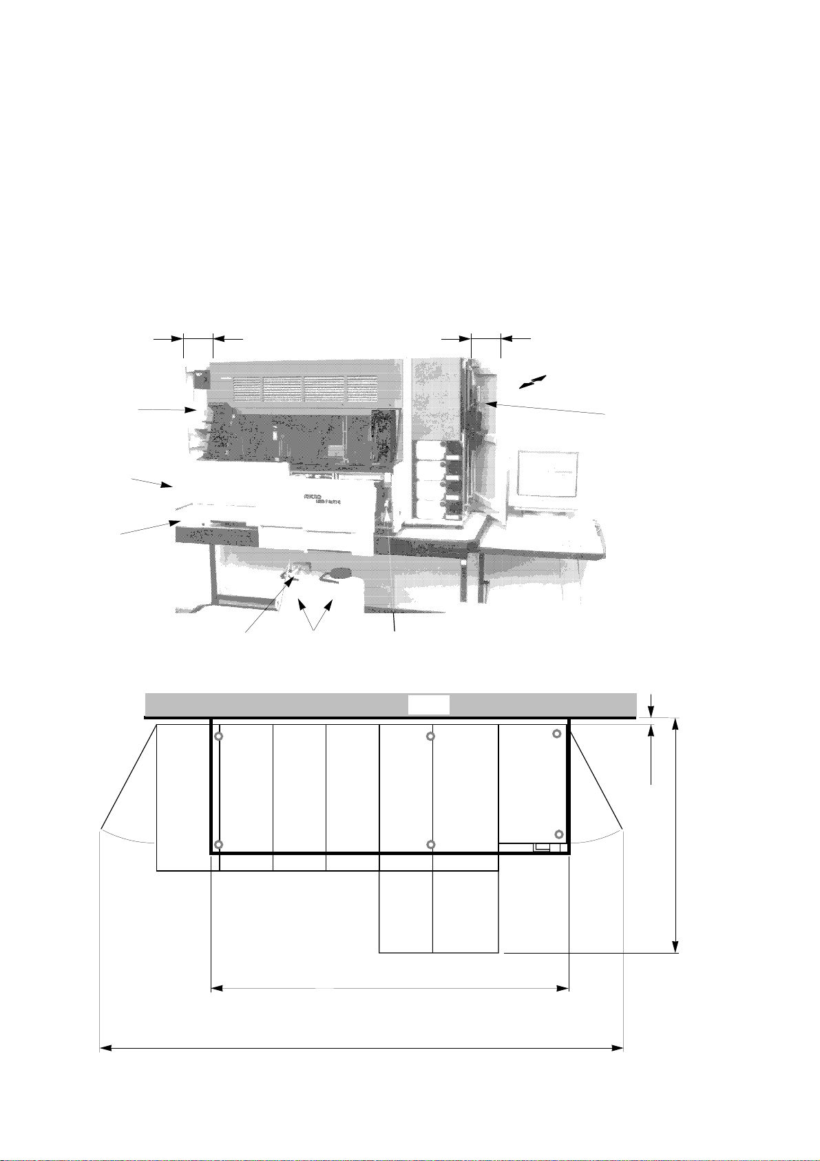
——— ML F.A.M.E. Service Manual V2.0 ———————————————————————————————————————————— SYSTEM ———
Workplace Environment
The instrument should be located within easy reach of a standard
electrical outlet (1 socket for the instrument, 1 for the computer, 1 for the
monitor and 1 for the (optional) printer).
We recommend using a Uninterruptable Power Supply (UPS). See User
Manual Section 11.1.1.
Ambient Temperature 15˚ - 35˚C
User
Manual
Power
Switch
Table must
withstand
200 kg/m
2
allow
at least
25 cm
Waste
cap
Waste
containers
allow
at least
25 cm
Allow 5 cm from wall
for proper ventilation
Tools
Use same
outlet for PC
& Microlab
F.A.M.E.
PC
connection
1-70
Wall
50 mm
1120 mm (drawer open)
Min. table size for 16/20 and 16/30: 1210 x 540
Min. table size for 24/20 and 24/30: 1420 x 540
Min. space needed (see table previous page)
Page 80

——— ML F.A.M.E. Service Manual V2.0————————————————————————————————————————————— SYSTEM ———
1.1.4.2 Unpacking Microlab F.A.M.E.
ATTENTION
Carefully store the Microlab F.A.M.E. packing material for future
shipping of the instrument.
Open the box and remove the cardboard top.
Remove accessory box, housing panel box, and protective inserts.
accessory box
Remove the instrument chassis.
Level the chassis by adjusting the chassis feet and align the chassis so
that it does not have to be moved once the modules are mounted
(assembled instrument is very heavy!!!).
Leave at least 5 cm space between the instrument and the wall for
proper ventilation.
Other considerations include operator comfort and easy access to
related supplies and equipment. For operator convenience, the front
edge of the instrument should be near to the front of the bench. Finally,
the position of the instrument must not hinder operation or accessibility
of other equipment in the work area.
housing panel box
1-71
Page 81

——— ML F.A.M.E. Service Manual V2.0 ———————————————————————————————————————————— SYSTEM ———
Adjust chassis to instrument configuration
Turn chassis upside down.
Loosen the 4 screws
fixing the chassis extension
Pull out the extension and
fix with the 4 screws
Chassis configuration16/20
1-72
Page 82

——— ML F.A.M.E. Service Manual V2.0————————————————————————————————————————————— SYSTEM ———
Chassis configuration 16/30
Chassis configuration 24/20
Chassis configuration 24/30
1-73
Page 83

——— ML F.A.M.E. Service Manual V2.0 ———————————————————————————————————————————— SYSTEM ———
1.1.4.3 Instrument assembly
ATTENTION
Install central modules first!
❐ The following installation procedure is for a 16/20 instrument
configuration.
❐ All required tools are in the accessory box.
NOTE
When placing the chassis on the table for module mounting, leave a
space of approx. 60 cm (24 inches) to the right of the chassis for the
container stack.
1.1.4.3.1 Installing INCUBATOR Module
Weight: 32 kg (71 lbs.)
Lift the module as shown in the following picture and set it onto the
chassis.
1-74
Page 84

——— ML F.A.M.E. Service Manual V2.0————————————————————————————————————————————— SYSTEM ———
Lower the rear of the module between the corresponding braces.
Slightly lift the front of the module and slide it carefully to the rear until
the front is level. Do not push the module all the way back until the
module is completely level!
Fix the module to the chassis by tightening the two captive screws.
1-75
Page 85

——— ML F.A.M.E. Service Manual V2.0 ———————————————————————————————————————————— SYSTEM ———
1.1.4.3.2 Installing WASHER/DISPENSER Module
Weight: 35 kg (77 lbs.)
ATTENTION
Never use the drawer handle when lifting the washer/dispenser module
or the end module! Use the module-frame handle provided underneath
the drawer panel.
correct
1-76
Page 86

——— ML F.A.M.E. Service Manual V2.0————————————————————————————————————————————— SYSTEM ———
incorrect
Using the height mover tool (in accessory box), raise the dispenser arm
so the drawer can be opened. Stop at least 2 cm (13/16”) before reaching
the top.
Now proceed as with the incubator module (see section 1.1.4.3.1).
1-77
Page 87

——— ML F.A.M.E. Service Manual V2.0 ———————————————————————————————————————————— SYSTEM ———
1.1.4.3.3 Installing ENTRY Module
Weight: 60 kg (132 lbs.)
ATTENTION
Two persons are needed to lift the entry module on to the chassis.
ATTENTION
Set the voltage selector switch to the local mains electricity supply
voltage.
Now proceed as with the incubator module (see section 1.1.4.3.1)
Remove the user manual from the accessory box and store it in the
entry module door.
1-78
Page 88

——— ML F.A.M.E. Service Manual V2.0————————————————————————————————————————————— SYSTEM ———
1.1.4.3.4 Installing END Module
Weight: 35 kg (77 lbs.)
ATTENTION
Never use the drawer handle when lifting the End Module! Use the
handle provided underneath the drawer panel. See “Installing
INCUBATOR Module” on page 74.
Using the height mover tool, raise the dispenser arm so the drawer can
be opened. Stop at least 2 cm (13/16”) before reaching the top.
Now proceed as with the incubator module (see section 1.1.4.3.1).
1-79
Page 89

——— ML F.A.M.E. Service Manual V2.0 ———————————————————————————————————————————— SYSTEM ———
1.1.4.3.5 Installing Main Shuttle Rail & Panels
ATTENTION
Do not attempt to open the reagent drawers without raising the
dispensers in the Washer/Dispenser and End Modules. Use the height
mover tool (stored in container stack) to raise the dispensers.
End ModuleWash/Disp. Module
Main shuttle rail
Open the drawers of the Washer/Dispenser Module and end module.
Slide the main shuttle rail towards the instrument into position.
Fix the rail with two screws p/n 400 309.
1-80
Page 90

——— ML F.A.M.E. Service Manual V2.0————————————————————————————————————————————— SYSTEM ———
MTP Transporter
The MTP (Micro-Titer Plate) transporter is attached to the main shuttle
rail with a screw. Carefully tighten the screw and check for proper fit.
Move the MTP transporter by hand from left to right and check that it
slides smoothly.
1-81
Page 91
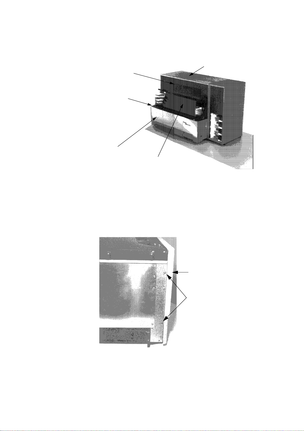
——— ML F.A.M.E. Service Manual V2.0 ———————————————————————————————————————————— SYSTEM ———
Installing Housing Panels
3 Hard Top
4 Upper Front
2 Cover Mains Power
1 Left Side Front
5 Transparent Cover
Left Side Front
Slide the
with the two screws.
left side front
panel from left to right into position -- fasten it
left side
front panel
screws
1-82
Page 92

——— ML F.A.M.E. Service Manual V2.0————————————————————————————————————————————— SYSTEM ———
Cover Mains Power
ATTENTION
Before fitting the Cover Mains Power, check that the voltage selector
switch is set to the local mains voltage. If necessary set to the correct
position.
Insert the tongue of the
side front panel
-- fasten the two mains panel screws.
cover mains power
into the groove of the
left
Hardtop
Make sure the front right corner of the
stack
fit properly.
Tighten the three screws on top.
hardtop
and the
strip container
1-83
Page 93

——— ML F.A.M.E. Service Manual V2.0 ———————————————————————————————————————————— SYSTEM ———
Upper Front
Slightly lift the front edge of the
upper front
under the
hardtop
hardtop
(1).
2
1
Screw ground cable onto Upper Front.
ground cable
, align the notches, and push the
Entry module
1-84
Slide the
upper front
from left to right into position (2).
Page 94

——— ML F.A.M.E. Service Manual V2.0————————————————————————————————————————————— SYSTEM ———
Transparent Cover
Lift the two transparent cover dampers to the upper position.
Press in the two locking pins and slide the
into position.
Remove the transparent film from the
transparent cover
exit stack.
transparent cover
as well as the
downwards
1-85
Page 95

——— ML F.A.M.E. Service Manual V2.0 ———————————————————————————————————————————— SYSTEM ———
1.1.4.3.6 Installing Container Stack
Weight: 24 kg (53 lbs.)
With the
container stack with the
container stack
strip container stack
tilted to the right, align the bottom of the
of the container stack into position.
, then carefully push the top
strip container stack
Adjust the container stack height by turning the container stack feet.
Check the gaps between the housing panels.
Remove the tools from the accessory box, open the container stack
door, and store them in the tool rack as shown below.
vernier calliper
mirror
tweezers angled
spillage tray
allen screwdrivers
2.5 & 3
rotor calibration pin
allen keys 2.5 & 3
plate fork
height mover tool
1-86
pocket lamp
Page 96

——— ML F.A.M.E. Service Manual V2.0————————————————————————————————————————————— SYSTEM ———
To connect the wash containers, pull out the coupling, turn, and push
into the wash container outlet.
1.1.4.3.7 Connecting Tubing and Cables
Open the reagent drawer (washer/dispenser), connect the cables and
press them into the grooves.
If the waste cap is not used, substitute plug p/n 146 373 must be
inserted in the waste cap socket for proper functioning of the instrument.
waste cap cable or
substitute plug
Connect the labeled end of the pump station cable to the external pump
station.
Connect the waste tube to the waste cap. Connect the wash/rinse tube
to the external pump station. Cut tubing to the appropriate lengths.
ATTENTION
The waste tube should be routed to the waste container in such a way
as to avoid dead volumes of liquid in the tube.
external pump station cable
grooves
✗✓
1-87
Page 97

——— ML F.A.M.E. Service Manual V2.0 ———————————————————————————————————————————— SYSTEM ———
Connect one end of the water separator venting tube to the Washer/
Dispenser Module and the other end to the sterilizing filter. Place the
sterilizing filter under the work bench out of the way.
venting tube from
water separator
waste tube
(to waste cap)
wash/rinse tube
(to ext. pump station)
ATTENTION
If two washers are being installed (24/20 or 24/30), pay special attention
to the external pump station tubing connections. The lower external
pump station connects to washer/dispenser 1. The upper external pump
station connects to washer/dispenser 2.
Ensure that tubings are neither twisted nor kinked.
8
7
To W/D 2
6
5
4
3
Washer/
Dispenser
Module
Washer/
Dispenser
Module
12
To W/D 1
2
1
1-88
Page 98

——— ML F.A.M.E. Service Manual V2.0————————————————————————————————————————————— SYSTEM ———
Install cables and tubing as shown below:
cable and tubing to
W/D module 2
cable and tubing to
W/D module 1
Open the End Module drawer and connect the computer cable (RS 232)
p/n 146 385.
press cable
into notch
Connect the other end of the computer cable to the corresponding serial
interface (RS 232) on your personal computer.
ATTENTION
Before continuing, check all connections! Incorrectly fitted cables may
result in damage to either the instrument or PC.
1-89
Page 99

——— ML F.A.M.E. Service Manual V2.0 ———————————————————————————————————————————— SYSTEM ———
1.1.4.3.8 Installing Reagent Container Carousel
ATTENTION
Installing the reagent carousel improperly will lead to syringe breakage
or reagent spillage!
Remove the reagent container carousel, reagent containers, and
syringes from the accessory box. For setting up the reagent carousel
refer to User Manual section 5.9.
Open the reagent drawers of the washer/dispenser module and the end
module. Lower and turn the reagent container carousel carefully until it
drops into position.
Carousel installed CORRECTLY.
1.
2.
Carousel installed INCORRECTLY.
1-90
Page 100

——— ML F.A.M.E. Service Manual V2.0————————————————————————————————————————————— SYSTEM ———
1.1.4.3.9 Computer Installation
ATTENTION
Before either
❐
connecting the computer to the instrument for the first time
❐
connecting a different computer to the instrument or
❐
connecting another instrument to the existing computer
always check that the photometer filter presettings in the software
correspond to the filters actually installed in the instrument.
The computer system consists of:
❐ monitor
❐ keyboard
❐ PC unit with
1
/2” disk drive and harddisk
3
!
❐ mouse
Installing the Computer System
Consult the manufacturers installation instructions for the installation of
the monitor, keyboard, PC unit and the mouse.
Stick the label shown below in a clearly visible place on the computer.
PC erst ausschalten, wenn OS/2 “shut down” ausgeführt worden ist.
Während eines RUN’s darf die Systemzeit des PC’s nicht verstellt werden.
Shut down OS/2 before switching off PC.
Do not change the OS/2 system time during a run.
Arrêter l’ordinateur seulement après l’exécution du OS/2 “shut down”.
Ne pas modifier l’heure du system OS/2 pendent un RUN.
Lable warning PC p/n 255 653
1-91
 Loading...