

Hamilton MICROLAB 500, MICROLAB 540B, MICROLAB 510B, MICROLAB 511C, MICROLAB 531C User Manual
...Page 1

Artisan Technology Group is your source for quality
new and certied-used/pre-owned equipment
• FAST SHIPPING AND
DELIVERY
• TENS OF THOUSANDS OF
IN-STOCK ITEMS
• EQUIPMENT DEMOS
• HUNDREDS OF
MANUFACTURERS
SUPPORTED
• LEASING/MONTHLY
RENTALS
• ITAR CERTIFIED
SECURE ASSET SOLUTIONS
SERVICE CENTER REPAIRS
Experienced engineers and technicians on staff
at our full-service, in-house repair center
Instra
Remotely inspect equipment before purchasing with
our interactive website at www.instraview.com
Contact us: (888) 88-SOURCE | sales@artisantg.com | www.artisantg.com
SM
REMOTE INSPECTION
View
WE BUY USED EQUIPMENT
Sell your excess, underutilized, and idle used equipment
We also offer credit for buy-backs and trade-ins
www.artisantg.com/WeBuyEquipment
LOOKING FOR MORE INFORMATION?
Visit us on the web at www.artisantg.com for more
information on price quotations, drivers, technical
specications, manuals, and documentation
Page 2

R
USERS
’
MANUAL
®
MICROLAB 500B/C
Artisan Technology Group - Quality Instrumentation ... Guaranteed | (888) 88-SOURCE | www.artisantg.com
Page 3

The MICROLAB ® 500 Series:
MICROLAB 510B, 530B, and 540B
and MICROLAB 511C, 531C, and 541C
User’s Manual
R
THE M
EASURE OF EXCELLENCE
Part Number 69176 (Rev. D)
Artisan Technology Group - Quality Instrumentation ... Guaranteed | (888) 88-SOURCE | www.artisantg.com
SM
.
Page 4

B Hamilton Company Instrument Warranty
Hamilton Company warrants this equipment (except valves*) to be free of defects in material
and workmanship for 12 months from the date of receipt. This warranty is extended to the buyer
of record on the original purchase order to Hamilton Company. Hamilton Company or an
authorized Hamilton representative agrees to repair or replace, at its option and free of charge
to the buyer at a normal place of business or at a Hamilton repair facility, any part or parts that
under proper and normal use prove to be defective during the warranty period.** Abuse,
unauthorized replacement of parts, modifications, or adjustments made by other than Company
or its assigned representatives voids this warranty.
This warranty gives you specific rights. No other warranties, expressed or implied, including
implications of warranties of merchantability and fitness for a particular product, are made.
Hamilton Company's liability on the sale of all products shall be limited to repair, replacement,
or refund of price of any defective product.**
Hamilton Company endeavors to provide prompt and satisfactory service.
*All Hamilton Company valves are warranted to be free of defects in material and
workmanship at the time of delivery.
**Hamilton Company reserves the right to refuse to accept the return of any instrument or valve
that has been used with radioactive or microbiological substances, or any other material that
may be deemed hazardous to employees of Hamilton Company.
© July 1999 by Hamilton Company
GASTIGHT is a registered trademark of Hamilton Company.
MICROLAB is a registered trademark licensed to Hamilton Company.
SANI-CLOTH is a registered trademark of Professional Disposables, Inc.
Artisan Technology Group - Quality Instrumentation ... Guaranteed | (888) 88-SOURCE | www.artisantg.com
Page 5

Instruction to the User
This equipment has been tested and found to comply with the limits for a class B
digital device, pursuant to part 15 of the FCC Rules. These limits are designed to
provide reasonable protection against harmful interference in an installation. This
equipment generates, uses, and can radiate radio frequency energy, and if not
installed and used in accordance with the instructions, may cause harmful
interference to radio communications. However, there is no guarantee that
interference will not occur in a particular installation. If this equipment does cause
harmful interference to radio or television reception, which can be determined by
turning the equipment off and on, the user is encouraged to try to correct the
interference by one or more of the following measures:
• Reorient or relocate the receiving antenna.
• Increase the separation between the equipment and receiver.
• Connect the equipment into an outlet on a circuit different from that to which
the receiver is connected.
• Consult the dealer or an experienced radio/TV technician for help.
This equipment has been verified to comply with the limits for a class B
computing device, pursuant to FCC Rules. In order to maintain compliance
with the FCC regulations, shielded cables must be used with this equipment .
Operation with non-approved equipment or unshielded cables is likely to
result in interference to radio and TV reception. The user is cautioned that
changes and modifications made to the equipment without the approval of
the manufacturer could void the user’s authority to operate this equipment.
Artisan Technology Group - Quality Instrumentation ... Guaranteed | (888) 88-SOURCE | www.artisantg.com
Page 6

Artisan Technology Group - Quality Instrumentation ... Guaranteed | (888) 88-SOURCE | www.artisantg.com
Page 7

Contents
Figures and Tables..................................................................xi
Preface ....................................................................PR–1
About the MICROLAB 500 Series of Instruments.....................PR–2
Upgrading Your MICROLAB 500 System..............................PR–3
About This Manual.................................................................PR–4
Conventions Used in This Manual ...........................................PR–5
A Word About Single Syringe Instruments ...............................PR–5
Chapter 1 Getting Started..................................................1–1
MICROLAB 500 Parts Lists.......................................................1 –2
A Brief Introduction to the MICROLAB 500B..............................1 – 8
Drive Unit..............................................................................1–8
Power Cord Connector Receptacle ................................... 1–13
Hand Probe or Footswitch Connector Receptacle..............1–13
Fuse Box.........................................................................1–13
Communications Settings.................................................1–13
Power On/Off Switch and Power Indicator Light.................1–14
Step/Prime Switch...........................................................1–14
Valve Assembly...............................................................1–15
Syringe Drive Arms........................................................... 1–15
Controller Unit........................................................................1–16
Pipettors/Probes................................................................... 1–18
Concorde Push-button Hand Pipettor/Probe.....................1–18
Dual Push-button Hand Pipettor/Probe ............................. 1–18
v
Artisan Technology Group - Quality Instrumentation ... Guaranteed | (888) 88-SOURCE | www.artisantg.com
Page 8

Disposable Tip Push-button Hand Pipettor/Probes ............ 1–19
Luer Lock Tip Push-button Pipette Hand Pipettor/Probe....1–19
Viscous Sample Push-button Hand Pipette
Pipettor/Probe.................................................................1–20
Footswitch..........................................................................1–20
Probe Button Functions ...................................................... 1–20
Chapter 2 Installing the MICROLAB 500 System ....................2–1
Overview of Installation Procedures...........................................2–3
Selecting a Location.................................................................2 – 3
Installing the Accessory Holder.................................................2 – 3
Selecting Communications Options.......................................... 2– 4
Installing Electrical Connections................................................2–6
Installing Valve Assemblies.......................................................2–8
Installing the Valve Assembly on the ML 510B/511C...............2–8
Installing Valve Assemblies on the
ML530B/531C and 540B/541C ............................................. 2– 9
Selecting, Installing, and Removing Syringes...........................2–10
Preparing Syringes for Installation........................................2–12
Installing Syringes...............................................................2–12
Removing Syringes.............................................................2–14
Selecting and Installing Tubing...............................................2–16
Selecting Tubing................................................................ 2–16
Installing Tubing..................................................................2–17
Chapter 3 Programming and Using the
MICROLAB 500B System.....................................3–1
Using the Controller Unit...........................................................3–3
Using the Arrow Keys............................................................3 –3
vi MICROLAB 510B/511C, 530B/531C, and 540B/541C User’s Manual
Artisan Technology Group - Quality Instrumentation ... Guaranteed | (888) 88-SOURCE | www.artisantg.com
Page 9

Using the Numeric Keypad....................................................3–4
Using the Run/Stop Key........................................................3 – 4
Using the Function Keys.......................................................3– 4
Editing Conventions............................................................. 3– 5
Powering on the MICROLAB 500..............................................3 – 6
The Main Menu........................................................................3 –7
Priming the MICROLAB 500.....................................................3–8
Preparing to Prime................................................................3–8
Using the Prime Function from the Main Menu......................3–11
Creating a New Method..........................................................3–13
Creating an Aliquot Dispense Method..................................3–17
Creating a Serial Dispense Method.......................................3–18
Creating a Dilution Method...................................................3–20
Creating a Pipette Method...................................................3–23
Creating a Titrate Method.....................................................3–25
Creating a Custom Method..................................................3–28
Running an Existing Method...................................................3 –30
Editing an Existing Method .....................................................3–32
Performing Manual Dilutions...................................................3–33
Performing Manual Dispenses................................................3–35
The Utilities Menu..................................................................3–37
Renaming an Existing Method.............................................3 –38
Deleting an Existing Method ................................................3–40
Copying a Method to a Custom Method................................3–41
Downloading a Method to the Drive unit................................3–42
Diagnostic and Configuration Menu......................................3–44
Changing the Default Language.......................................3–44
Contents vii
Artisan Technology Group - Quality Instrumentation ... Guaranteed | (888) 88-SOURCE | www.artisantg.com
Page 10

Setting the Baud Rate to the Drive Unit..............................3–45
Turning Caps Lock On and Off..........................................3–46
Performing the Display Test..............................................3–46
Performing the Keyboard Test .......................................... 3–46
Sample MICROLAB 510B Application Configurations...............3–47
Single Syringe Dispensing............................................ 3–47
Sample MICROLAB 530B Application Configurations...............3–48
Example 1: Dilutions......................................................3–48
Example 2: Dilutions......................................................3–49
Sample MICROLAB 540B Application Configurations...............3–50
Example 1: Dual Dispensing..........................................3–50
Example 2: Using the Dual Dispenser for
Single Dispensing......................................................... 3–50
Chapter 4 Caring for the MICROLAB 500..............................4–1
Deciding When to Clean the MICROLAB 500.............................4–2
Cleaning the Fluid Path of the MICROLAB 500..........................4 –2
Cleaning Syringes and Tubing..................................................4 – 3
Cleaning the Exterior of the MICROLAB 500..............................4–4
Chemical Compatibility..............................................................4–5
Storing the MICROLAB 500......................................................4 – 6
Replacing Batteries..................................................................4 – 6
Chapter 5 Troubleshooting the MICROLAB 500.................... 5 –1
Error Message Code Guide.......................................................5–2
Audible Messages.................................................................5–10
Troubleshooting Guide.......................................................... 5–11
Getting Technical Support ......................................................5–15
Returning Instruments for Repair.............................................5–16
viii MICROLAB 510B/511C, 530B/531C, and 540B/541C User’s Manual
Artisan Technology Group - Quality Instrumentation ... Guaranteed | (888) 88-SOURCE | www.artisantg.com
Page 11

Appendixes
Appendix A Technical Specifications for the MICROLAB 500........................A–1
Pin Outs for RS-232 and TTL Ports...........................................A –3
Appendix B Instrument Performance Test Reports.......................................B – 1
Appendix C Ordering Parts and Accessories for the MICROLAB 500.............C–1
Appendix D Chemical Compatibility of the MICROLAB 500............................ D –1
Appendix E Communication Protocols.........................................................E – 1
Hamilton Protocol 1/RNO+ Syntax Overview..........................E –1
Auto-addressing ................................................................E–2
Data Transfer Format ...........................................................E-4
Data String Components.....................................................E-5
DIN Protocol/BDZ+ Syntax..................................................... E–7
Hardwire-addressing..........................................................E – 8
Auto-addressing .................................................................E-8
Extablishing a Data Transfer Session....................................E-9
Terminating a Data Transfer Session................................... E-10
Data Transfer Session......................................................E–10
Data Block Format............................................................ E–10
Data String Components...................................................E-11
Broadcast Addressing ....................................................... E-16
Stored Methods................................................................E-16
Stored Method Definition..................................................E-16
Creating Stored Methods..................................................E-16
Stored Method Execution.................................................E-17
Appendix F Protocol Command Summary....................................................F –1
Channel Selection Commands.............................................F-2
Contents ix
Artisan Technology Group - Quality Instrumentation ... Guaranteed | (888) 88-SOURCE | www.artisantg.com
Page 12

Initialization Commands .......................................................F-3
Syringe Positioning Commands ........................................... F-4
Valve Positioning Commands..............................................F-5
Timer and Digital I/O Commands...........................................F-6
Execution Commands ......................................................... F-7
Instrument Control Commands.............................................F-8
Syringe Parameter Change..................................................F-9
Valve Parameter Change...................................................F-10
Stored Method Parameter Change.....................................F-11
Instrument Information Requests.......................................F-11
Instrument Status Requests.............................................. F-13
Syringe Parameter Request...............................................F-19
Valve Parameter Request..................................................F-20
Timer and Digital I/O Requests...........................................F-21
Firmware Version Request.................................................F-22
ASCII Chart..........................................................................F-22
ML500B Default Environmental Parameters...........................F-26
ML500B Command Buffer .................................................... F-26
ML500B Methods ................................................................ F-27
ML500B Specific Protocol Information...................................F-27
Glossary ....................................................................GL–1
Index .....................................................................IN–1
x MICROLAB 510B/511C, 530B/531C, and 540B/541C User’s Manual
Artisan Technology Group - Quality Instrumentation ... Guaranteed | (888) 88-SOURCE | www.artisantg.com
Page 13

Figures and Tables
Preface
Figure PR–1 The MICROLAB 500 Series of Instruments.........PR–2
Chapter 1
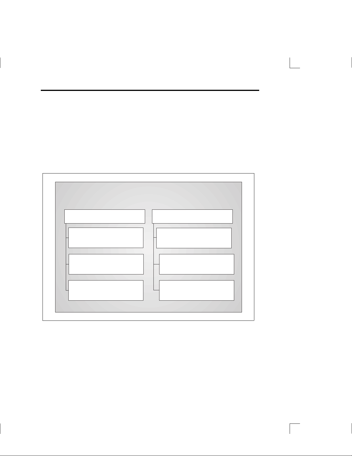
Figure 1–1 MICROLAB 500B System Components...............1– 3
Figure 1–2 MICROLAB 500B Shipping Kit Components........1 –5
Figure 1–3 Small Parts Kit.....................................................1–6
Figure 1–4 Tubing Kit........................................................... 1 –7
Figure 1–5 Front View of theML510B Single
Syringe Dispenser.............................................. 1 – 9
Figure 1–6 Front View of the ML530B Dual Syringe Diluter... 1–10
Figure 1–7 Front View of the ML540B Dual
Syringe Dispenser............................................ 1–11
Figure 1–8 Rear View of the ML510B, 530B, and 540B........1–12
Figure 1–9 The Controller Unit............................................1–17
Figure 1–10 The Concorde, the Disposable Tip, and the Dual Hand
Pipettor/Probes ................................................1–19
Chapter 2
Table 1–1 MICROLAB 500 System Descriptions...................1–2
Table 1–2 MICROLAB 500B Shipping Kit............................. 1 – 4
Table 1–3 Small Parts Kit #35888 (For All Models).................1– 6
Table 1–4 Tubing Kit #35887 (For All Models)...................... 1– 7
Figure 2–1 Overview of Installation Procedures......................2 –2
Figure 2–2 Installing Electrical Connections...........................2 –7
Figure 2–3 Installing a Valve Assembly on the ML510B.......... 2– 8
Figures and Tables xi
Artisan Technology Group - Quality Instrumentation ... Guaranteed | (888) 88-SOURCE | www.artisantg.com
Page 14

Figure 2–4 Installing a Valve Assembly on the
ML530B and 540B..............................................2 –9
Figure 2–5 The TLL-type Dispenser/Diluent Syringe............ 2–11
Figure 2–6 The TLLX-type Dispenser/Diluent Syringe..........2–11
Figure 2–7 The DX-type Sample Syringe.............................2–11
Figure 2–8 Installing a Syringe ............................................2–13
Figure 2–9 Removing a Syringe..........................................2–15
Figure 2–10 ML510B Valve and Tubing Connections............ 2–18
Figure 2–11 ML530B Valve with a D Configuration Syringe.....2–19
Figure 2–12 ML530B Valve with Two TLLX or TLL Syringes ... 2–19
Figure 2–13 ML540B Valve and Tubing Connectors .............. 2–20
Figure 2–14 Using the Tubing Reducer with the
Dual Hand Probe...............................................2–21
Table 2–1 Communications Switches and Ports....................2–4
Table 2–2 Reagent/Diluent Syringes
(TLL and TLLX-types)........................................2–10
Table 2–3 Sample Syringes (DX-type)................................2–11
Table 2–4 Tubing Selection Guide.....................................2–16
Chapter 3
Figure 3–1 Using the MICROLAB 500B.................................3–1
Figure 3–2 Overview of MICROLAB 500B Functions..............3–2
Figure 3–3 The Controller Unit..............................................3–3
Figure 3–4 Priming the MICROLAB 500..............................3–10
Figure 3–5 The Utilities Menu.............................................3–37
Figure 3–6 Single Syringe Dispensing ................................3–47
Figure 3–7 Dilutions........................................................... 3–48
Figure 3–8 Serial Dilutions..................................................3–49
Figure 3–9 Dual Dispensing................................................ 3–50
Figure 3–10 Using the Dual Dispenser for Single Dispensing.. 3–51
xii MICROLAB 510B/511C, 530B/531C, and 540B/541C User’s Manual
Artisan Technology Group - Quality Instrumentation ... Guaranteed | (888) 88-SOURCE | www.artisantg.com
Page 15

Chapter 5
Appendix A
Appendix B
Appendix C
Table 3–1 Function Key Actions .......................................... 3– 4
Table 5-1 Error Message Code Guide..................................5–2
Table 5–2 Audible System Messages ................................5–10
Table 5–3 Troubleshooting Guide .....................................5–11
Table A–1 Technical Specifications for the MICROLAB 500...A–1
Table A–2 Accuracy and Precision.......................................A–2
Figure B–1 Sample Performance Test Report........................B–2
Table C–1 Reagent/Diluent Syringe Replacement Parts ........C–1
Table C–2 Sample Syringe Replacement Parts .....................C –2
Table C–3 Valve Assemblies................................................C–2
Table C–4 Tubing ...............................................................C– 2
Table C–5 Pipettors/Probes ...............................................C –3
Table C–6 Parts and Accessories......................................... C –3
Appendix D
Appendix E
Appendix F
Table D–1 Chemical Compatibility.........................................D–1
Table E–1 Protocol 1/RNO+ Control Characters....................E– 2
Table E–2 DIN Protocol/BDZ+ Control Characters.................E– 8
Table F-1 Channel Selection Commands.............................F–2
Table F-2 Initialization Commands........................................ F-3
Table F-3 Syringe Positioning Commands............................ F-4
Figures and Tables xiii
Artisan Technology Group - Quality Instrumentation ... Guaranteed | (888) 88-SOURCE | www.artisantg.com
Page 16

Table F-4 Valve Positioning Commands ...............................F-5
Table F-5 Timer and Digital I/O Commands............................F-6
Table F-6 Execution Commands.......................................... F-7
Table F-7 Instrument Control Commands.............................. F-8
Table F-8 Syringe Parameter Change................................... F-9
Table F-9 Valve Parameter Change.................................... F-10
Table F-10 Stored Method Parameter Change......................F-11
Table F-11 Instrument Information Requests ........................F-11
Table F-12 Instrument Status Request.................................F-13
Table F-13 Syringe Parameter Request................................ F-19
Table F-14 Valve Parameter Request...................................F-20
Table F-15 Timer and Digital I/O Requests ............................F-21
Table F-16 Firmware Version Request..................................F-22
Table F-17 ASCII Chart........................................................F-23
xiv MICROLAB 510B/511C, 530B/531C, and 540B/541C User’s Manual
Artisan Technology Group - Quality Instrumentation ... Guaranteed | (888) 88-SOURCE | www.artisantg.com
Page 17

Preface Welcome to the World of
Hamilton Precision
Instruments
Congratulations on your purchase of a Hamilton MICROLAB 500
system. The Hamilton MICROLAB 500 is a versatile, semiautomatic, precision liquid processor. Various models of the
MICROLAB 500 function as either single- or dual-syringe
diluter/dispensers.
The MICROLAB 500 functions on the principal of liquid/liquid
displacement. At the heart of each MICROLAB 500 system is a
highly efficient, precision stepper motor drive that is combined
with world-famous Hamilton GASTIGHT syringes. The result is
a precise and accurate instrument that is very easy to set up
and use.
With proper care and maintenance, your new MICROLAB 500
system will serve you faithfully. To learn about the proper care
and maintenance of your investment, please take the time to read
this manual. Also, please read the warranty information that
appears on the copyright page in this manual and on the
separate warranty sheet that is included in your MICROLAB 500
shipping kit.
The Hamilton Company thanks you for purchasing this
Hamilton product. Welcome to the world of Hamilton precision
instruments!
PR–1
Artisan Technology Group - Quality Instrumentation ... Guaranteed | (888) 88-SOURCE | www.artisantg.com
Page 18
About the MICROLAB 500 Series of Instruments
All of the MICROLAB 500 systems feature four common pipette modes: fill,
dispense, auto-refill, and prime. The systems are capable of performing accurate
and precise transfer pipetting, and of performing automated dilutions up to 1:25,000.
The instruments can also dispense up to 50 mL per cycle. Figure PR–1 provides an
overview of the MICROLAB 500 Series of Instruments.
Figure PR–1 The MICROLAB 500 Series of Instruments
The Microlab 500 Series of Instruments
Single Syringe Instruments
Controller without memory:
• Microlab 501A dispenser
Controller with memory:
• Microlab 510B diluter/dispenser
Computer-controlled:
• Microlab 511C diluter/dispenser
Dual Syringe Instruments
Controller without memory:
• Microlab 503A diluter
• Microlab 504A dispenser
Controller with memory:
• Microlab 530B diluter/dispenser
• Microlab 540B dispenser
Computer-controlled:
• Microlab 531C diluter/dispenser
• Microlab 541C dispenser
PR–2 MICROLAB 510B/511C, 530B/531C, and 540B/541C User’s Manual
Artisan Technology Group - Quality Instrumentation ... Guaranteed | (888) 88-SOURCE | www.artisantg.com
Page 19

The MICROLAB 500 Series of instruments consists of three different lines of
diluter/dispensers.
• Controller without memory: Use the controller unit to manually enter methods.
This controller unit does not have memory, so methods cannot be stored.
• Controller with memory: This controller unit has memory, allowing you to
program and store your own custom methods. Or, use the controller unit to run
manual methods. Any instrument that uses this controller can also be computer
controlled.
• Computer controlled: No controller unit is included; use a computer to operate
the instrument.
The MICROLAB 510B/511C, 530B/531C, and 540B/541C are described in this
manual.
• The MICROLAB 510B/511C is a single syringe dispenser designed for single
precision dispensing applications.
• The MICROLAB 530B/531C is a dual syringe diluter designed for repetitive
dilution applications.
• The MICROLAB 540B/541C is a dual syringe dispenser designed for precision
dispensing applications that require more than one liquid to be dispensed at a
time.
Upgrading Your MICROLAB 500 System
Both the MICROLAB 510B/511C and 530B/531C systems can be upgraded to
MICROLAB 540B/541C systems. For upgrade information or for information about
purchasing any of the MICROLAB 500 models, contact your authorized Hamilton
sales representative or contact Hamilton Company.
In the United States:
Hamilton Company, P.O. Box 10030, Reno, Nevada 89520–0012
Telephone Numbers (in the USA and Canada):
Technical/Customer Service 1–800–648–5950 8 a.m. to 5 p.m. PST
Instrument Service 1–800–527–5269
Preface PR–3
Artisan Technology Group - Quality Instrumentation ... Guaranteed | (888) 88-SOURCE | www.artisantg.com
Page 20

Outside the USA and Canada:
+1–775–858–3000
Fax Number: +1–775–856–7259
In Switzerland:
Hamilton Bonaduz AG, Ch–7402, P.O. Box 26,
Bonaduz, Switzerland
Telephone Number: +41–81–660–60–60
Fax Number: +41–81–660–60–70
About This Manual
This manual provides technical information about the MICROLAB 510B/511C,
530B/531C, and 540B/541C, and is divided into chapters that cover the following
topics:
• Chapter 1, Getting Started, provides an overview of the MICROLAB 500
system, including a complete parts list and a brief description of the system
components.
• Chapter 2, Installing the MICROLAB 500, describes how to set up the system.
• Chapter 3, Using the MICROLAB 500, provides step-by-step instructions for
using the system. It also provides sample applications.
• Chapter 4, Caring for the MICROLAB 500, describes everyday maintenance
techniques.
• Chapter 5, Troubleshooting, contains tables that list system messages and their
meanings, and common problems and their solutions.
• The Appendixes provide detailed information, such as technical specifications,
ordering information, etc.
• The Glossary defines terms used in this manual.
• The Index provides a quick-reference to the topics described in this manual.
PR–4 MICROLAB 510B/511C, 530B/531C, and 540B/541C User’s Manual
Artisan Technology Group - Quality Instrumentation ... Guaranteed | (888) 88-SOURCE | www.artisantg.com
Page 21

Conventions Used in This Manual
Throughout this manual symbols are used to call your attention to various kinds of
information.
A Warning! Information that is essential for avoiding personal
injury is flagged with the International Warning
Symbol and appears like this in the text.
▲ Important Information that is essential for avoiding damage to
equipment appears like this in the text.
✱ Note: Interesting information or information that can help
improve system performance appears like this in the text. ✱
System messages and prompts that appear on the controller unit’s display screen
are shown in courier font. Items that are selected and user input appear in
boldface courier.
A
▲
A Word About Single Syringe Instruments
Throughout this manual you will see references to multiple syringes, volumes,
speeds, and to the right-side controls. All screen examples show the use of dual
syringe instruments. If you are using a MICROLAB 510B/511C single syringe
dispenser, please disregard these references. The right-side functions are not
available on single syringe instruments.
Any operational differences between the single and the dual syringe instruments
are called out in the text.
Preface PR–5
Artisan Technology Group - Quality Instrumentation ... Guaranteed | (888) 88-SOURCE | www.artisantg.com
Page 22

Artisan Technology Group - Quality Instrumentation ... Guaranteed | (888) 88-SOURCE | www.artisantg.com
Page 23

Chapter 1 Getting Started
This chapter provides a brief overview of the MICROLAB 500
system. Information in this chapter includes:
• MICROLAB 500 parts lists
• MICROLAB 500 components
– the drive unit
– the controller unit
– hand pipettors/probes
All MICROLAB 500 instruments come with everything you need
to start using the system, with the exception of syringes. You
must separately purchase syringes for use with the MICROLAB
500 systems. For complete lists of syringes, accessories, and
replacement parts for the MICROLAB 500, see Appendix C,
Ordering Parts and Accessories for the MICROLAB 500.
✱ Note: Contact your local delivery company if you
notice any visual damage to the MICROLAB 500
shipping package or to its contents. Also, you
may want to save the shipping container in case
you ever need to return the instrument for
service. ✱
1–1
Artisan Technology Group - Quality Instrumentation ... Guaranteed | (888) 88-SOURCE | www.artisantg.com
Page 24

MICROLAB 500 Parts Lists
This section includes complete parts lists for the MICROLAB 500 systems. After you
unpack your MICROLAB 500, check to see that you have received all parts before
attempting to set up the system. The parts lists are presented in four separate tables
with four corresponding figures.
Table 1–1 lists the programmable models in the MICROLAB 500 series, their
components, and each component’s part number. Figure 1–1 shows these components.
Table 1–1 MICROLAB 500 System Descriptions
Model* Part # Drive
MICROLAB
510B 115V
MICROLAB
510B 220V
MICROLAB
530B 115V
MICROLAB
530B 220V
MICROLAB
540B 115V
MICROLAB
540B 220V
ML510115 35890 35893 69176 (English)
ML510220 35890 35893 same as above 355010 35792
ML530115 35891 35893 same as above 6541000 35793
ML530220 35891 35893 same as above 355010 35793
ML540115 35892 35893 same as above 6541000 35794
ML540220 35892 35893 same as above 355010 35794
Unit
Part #
Controller
Unit &
Cord
Part #
Manual Part # Power
69182 (French)
69180 (German)
69186 (Portuguese)
69188 (Spanish)
Shipping
Cord
6541000 35792
Kit
Part #
* All MICROLAB 500C models come with the drive unit, the manual, a power cord,
and a valve. The MICROLAB 500 C does not come with a controller or a shipping
kit.
1–2 MICROLAB 510B/511C, 530B/531C, and 540B/541C User’s Manual
Artisan Technology Group - Quality Instrumentation ... Guaranteed | (888) 88-SOURCE | www.artisantg.com
Page 25

Figure 1–1 MICROLAB 500 System Components (items shown are
R
R
not to scale)
R
R
1
2
3
4
5
6
7
8
9
.
STEP
PRIME
POWER
Dual Drive Unit
Part # 35891 or 35892
(Microlab 530B/531C or 540B/541C)
0
Controller Unit and Cord
Part # 35893
(not with 500C models)
Stop
Run
R
R
PRIME
POWER
Single Drive Unit
Part # 35890
(Microlab 510B/511C)
Power Cord
Part # 6541000 or 355010
Shipping Kit
Part # 35792 (Microlab 510B)
Part # 35793 (Microlab 530B)
Part # 35794 (Microlab 540B)
STEP
R
Manual
Part # 69176
Chapter 1 Getting Started 1–3
Artisan Technology Group - Quality Instrumentation ... Guaranteed | (888) 88-SOURCE | www.artisantg.com
Page 26

Table 1–2 lists the components that make up the MICROLAB 500B Shipping Kit
(shown as a box in Figure 1–1). Figure 1–2 shows these components.
Table 1–2 MICROLAB 500B Shipping Kit
Shipping Kit*
Part #
MICROLAB
510B
35792
MICROLAB
530B
35793
MICROLAB
540B
35794
Valve Part # Hand Probe Part
#
HV Valve
35825
Concorde
Probe
35529
Diluter
Valve
35844
Dispenser
Valve
35842
Concorde
Probe
35529
Dual Hand
Probe
35767
Small Parts Kit
Part #
35888 35887
35888 35887
35888 35887
Tubing Kit
Part #
2 items
*The MICROLAB 500C is standard with only the valve. All other parts must be
ordered separately.
1–4 MICROLAB 510B/511C, 530B/531C, and 540B/541C User’s Manual
Artisan Technology Group - Quality Instrumentation ... Guaranteed | (888) 88-SOURCE | www.artisantg.com
Page 27
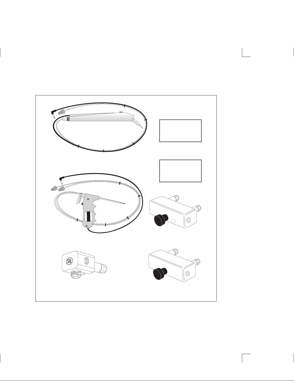
Figure 1–2 MICROLAB 500B Shipping Kit Components (items
R
shown are not to scale)
Small Parts Kit
Part # 35888
Concorde Probe
(Microlab 510B/511C or 530B/531C)
Part # 35529
Tubing Kit
Part # 35887
Dual Hand Probe
Part # 35767
(Microlab 540B/541C)
HV Valve
Part # 35825
(Microlab 510B/511C)
Dispenser Valve
Part # 35842
Diluter Valve
Part # 35844
Chapter 1 Getting Started 1–5
Artisan Technology Group - Quality Instrumentation ... Guaranteed | (888) 88-SOURCE | www.artisantg.com
Page 28
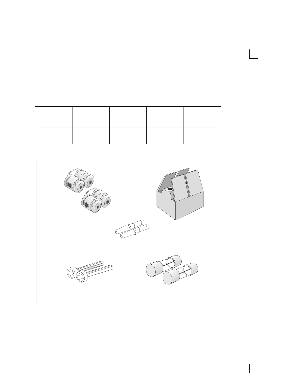
Table 1–3 lists the components that make up the MICROLAB 500B Small Parts Kit
(shown as a box in Figure 1–2). Figure 1–3 shows these components.
Table 1–3 Small Parts Kit #35888 (For All 500B Models)
Tubing Clips
Part #
230010
2 items
1 AMP Fuses
Part #
1524-01
2 items
Accessory
Holder
Part #
35783
1 item
Screws
Part #
16500
2 items
Figure 1–3 Small Parts Kit (items shown are not to scale)
(2) Tubing Clips
Part # 230010
Tubing Reducers
Part # 35770
Accessory
Holder
Part # 35783
Tubing
Reducers
Part #
35770
2 items
(2) Screws
Part # 16500
(2) Fuses
Part # 1524-01
1–6 MICROLAB 510B/511C, 530B/531C, and 540B/541C User’s Manual
Artisan Technology Group - Quality Instrumentation ... Guaranteed | (888) 88-SOURCE | www.artisantg.com
Page 29

Table 1–4 lists the components that make up the MICROLAB 500 Tubing Kit (shown
as a box in Figure 1–2). Figure 1–4 shows these components.
Table 1–4 Tubing Kit #35887 (For All 500B Models)
12 ga. x 650 mm
Fill Tubing (not
tapered)
Part #
18 ga. x 650 mm
Fill Tubing (not
tapered)
Part #
12 ga. x 900 mm
Dispense Tubing
(tapered)
Part #
18 ga. x 900 mm
Dispense Tubing
(tapered)
Part #
240000* 240010* 240360* 240130*
* M6 threaded hubs are used on all tubing.
Figure 1–4 Tubing Kit (items shown are not to scale)
12 ga. Fill Tubing
Part # 240000
12 ga. Dispense Tubing
Part # 240360
18 ga. Fill Tubing
Part # 240010
18 ga. Dispense Tubing
Part # 240130
For complete lists of syringes, accessories, and replacement parts for the
MICROLAB 500, see Appendix C, Ordering Parts and Accessories for the
MICROLAB 500.
Chapter 1 Getting Started 1–7
Artisan Technology Group - Quality Instrumentation ... Guaranteed | (888) 88-SOURCE | www.artisantg.com
Page 30

A Brief Introduction to the MICROLAB 500B
The MICROLAB 510B, 530B, and 540B systems each consist of three basic units.
These units include:
• a drive unit
• a controller unit
• a hand probe
This section briefly describes these units and the individual components that
comprise each unit. See Chapter 2, Installing the MICROLAB 500, for complete
installation instructions; see Chapter 3, Using the MICROLAB 500, for complete
usage instructions.
Drive Unit
The drive unit is the heart of each MICROLAB 500 system. The drive unit contains
a precision drive motor, the syringe drive arms, the valve assembly, the power
switches, and the connector receptacles. These features allow you to control other
sub-assemblies, and together they create a very versatile and functional
instrument.
Figure 1– 5 shows the front view of the MICROLAB 510B single syringe
diluter/dispenser. In this figure, the controller unit rests on top of the drive unit and
a syringe is attached to the syringe drive arm.
A Warning! This warning label appears on the front panel of the
ML500. It indicates that a pinch hazard exists when
the syringe drive is moving.
1–8 MICROLAB 510B/511C, 530B/531C, and 540B/541C User’s Manual
Artisan Technology Group - Quality Instrumentation ... Guaranteed | (888) 88-SOURCE | www.artisantg.com
A
Page 31

Figure 1–5 Front View of the MICROLAB 510B Single Syringe
Diluter/Dispenser
Input
12
4
7
.
56
89
0
R
R
3
Run
Stop
R
R
Hand Probe
Connector
Receptacle
Output
R
STEP
PRIME
Step/Prime
Switch
Power
Indicator
Light
Power
POWER
On/Off
Switch
Chapter 1 Getting Started 1–9
Artisan Technology Group - Quality Instrumentation ... Guaranteed | (888) 88-SOURCE | www.artisantg.com
Page 32
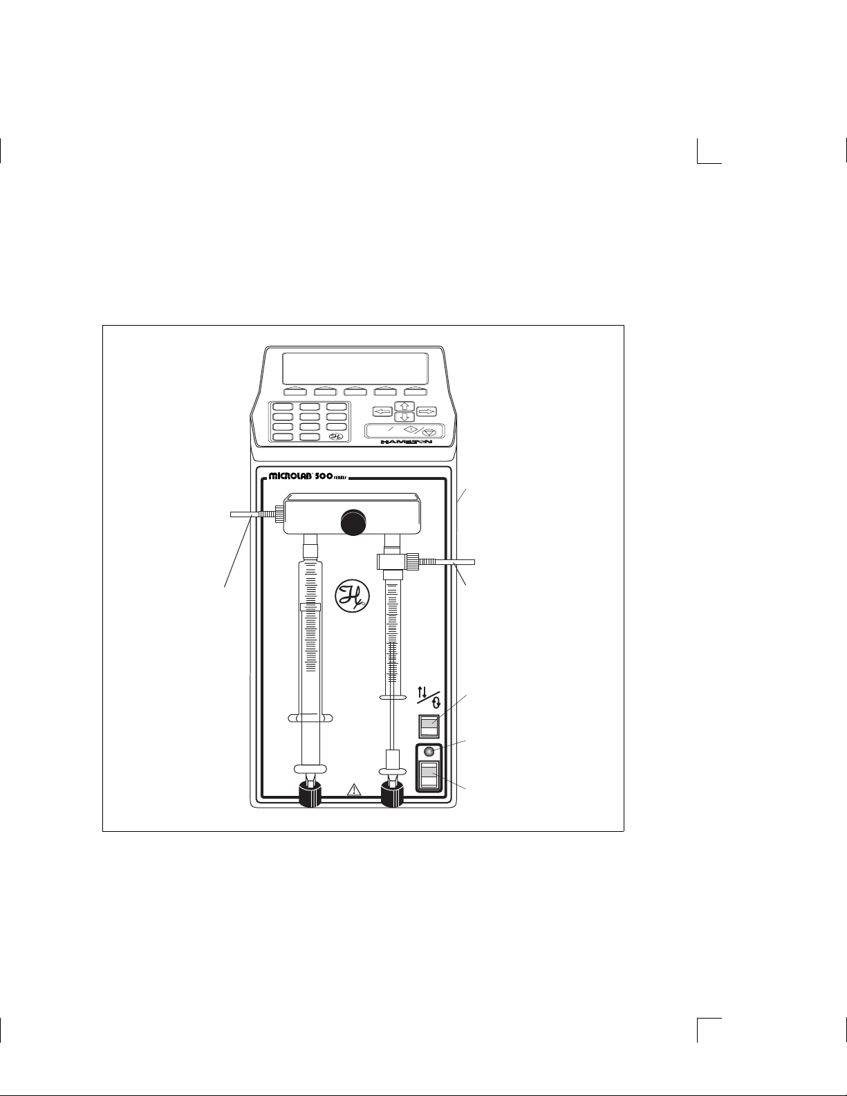
Figure 1–6 shows the front view of the MICROLAB 530B dual syringe diluter. In
this figure, the controller unit rests on top of the drive unit and syringes are
attached to the syringe drive arms.
Figure 1–6 Front View of the MICROLAB 530B Dual Syringe Diluter
12
4
7
.
56
89
0
R
3
Run
Stop
R
R
Hand Probe
Connector
Receptacle
OutputInput
R
STEP
Step/Prime
PRIME
Switch
Power
Indicator
Light
Power
POWER
On/Off
Switch
1–10 MICROLAB 510B/511C, 530B/531C, and 540B/541C User’s Manual
Artisan Technology Group - Quality Instrumentation ... Guaranteed | (888) 88-SOURCE | www.artisantg.com
Page 33
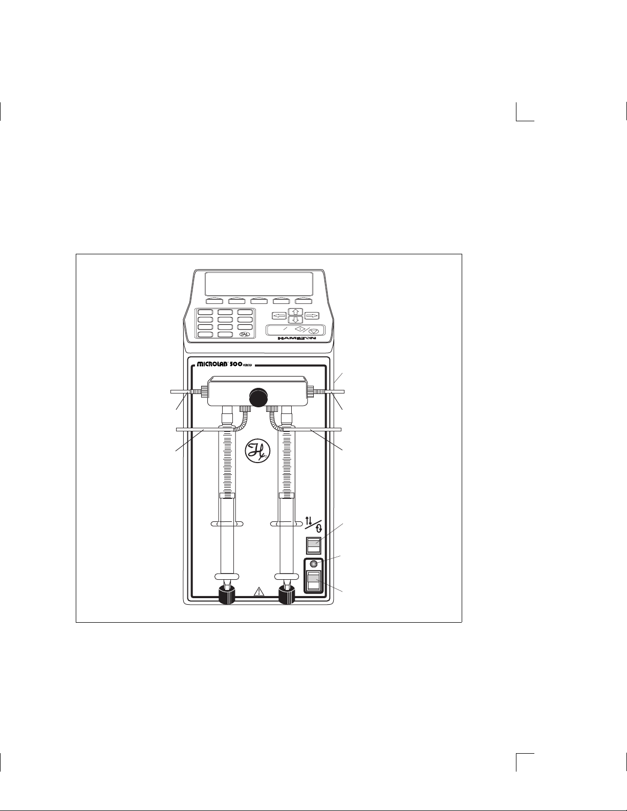
Figure 1–7 shows the front view of the MICROLAB 540B dual syringe dispenser. In
this figure, the controller unit rests on top of the drive unit and syringes are
attached to the syringe drive arms.
Figure 1–7 Front View of the MICROLAB 540B Dual Syringe
Dispenser
Input
Output
12
4
7
.
56
89
0
R
3
Run
Stop
R
R
Hand Probe
Connector
Receptacle
Input
R
STEP
PRIME
Output
Step/Prime
Switch
Power
Indicator
Light
Power
POWER
On/Off
Switch
Chapter 1 Getting Started 1–11
Artisan Technology Group - Quality Instrumentation ... Guaranteed | (888) 88-SOURCE | www.artisantg.com
Page 34
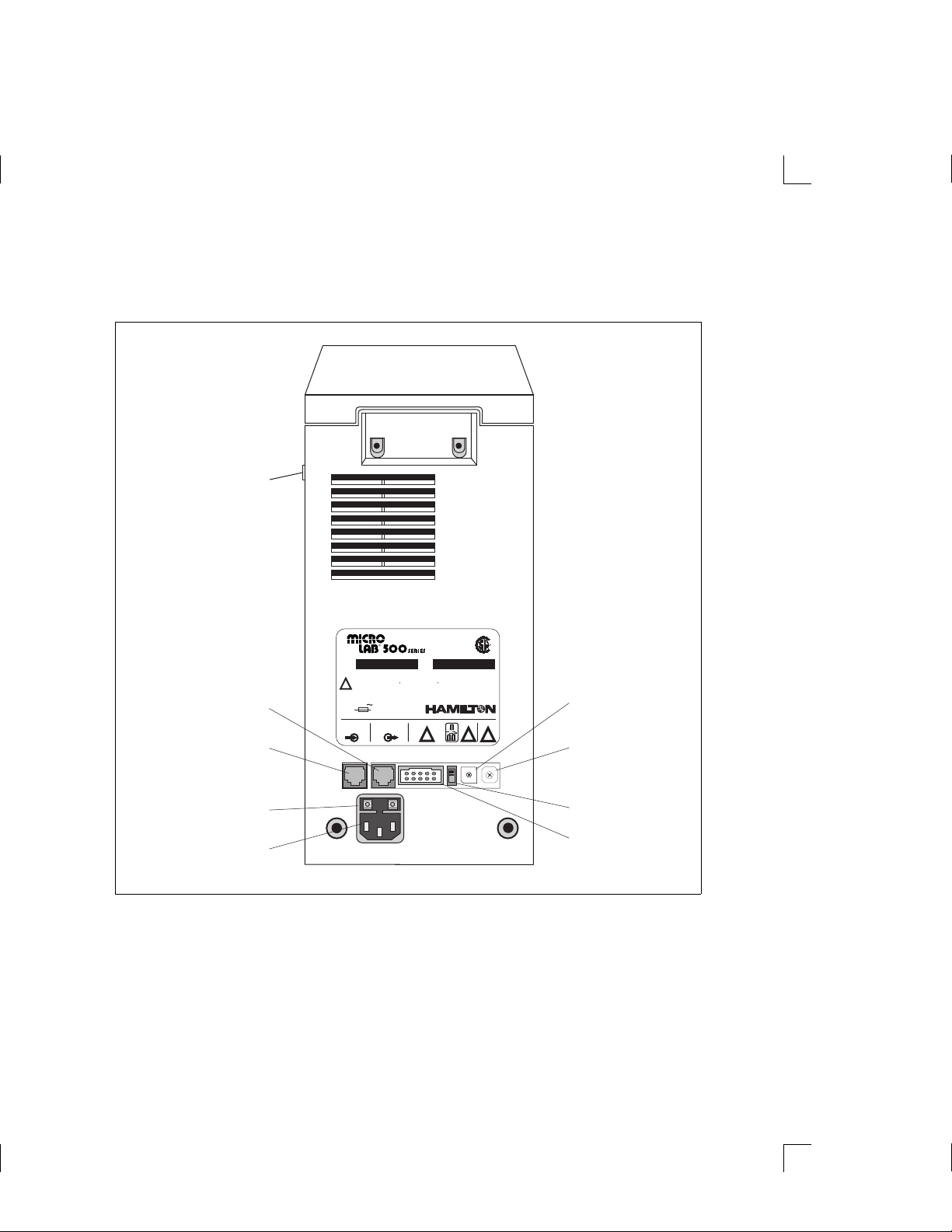
Figure 1–8 shows the rear view of all units.
Figure 1–8 Rear View of the MICROLAB 500.
Hand Probe
Connector
Receptacle
LR-52122
BAUD
!
5
4
3
2
6
0
1
R
RENO, NEVADA
UNIT #
!
8
7
6
7
5
8
4
9
3
2
1
R
Baud Rate
Switch
Protocol
9
A
B
C
D
E
F
0
Switch
Loopback
Switch
TTL Port
RS-232 OUT
Receptacle
Controller Unit
Connector
Receptacle
(RS-232 IN)
Fuse Box
Power Cord
Connector
R
RS-232
OUT
PART
NO.
MANUFACTURED BY
TTL
!
SERIAL
NO.
WARNING: DISCONNECT SUPPLY BEFORE SERVICING.
HIGH LEAKAGE CURRENT-ENSURE PROPER GROUNDING.
AVERTISSEMENT: COUPER LALIMENTATION AVANT L ENTRETIEN ET DEPANNAGE.
!
COURANT DEFUITE ELEVE-FOURNIER UNE MISE A LA TERRE EFFICACE.
WARNUNG: FUER SERVICEARBEITEN STROMZUFUHR UNTERBRECHEN.
HOHER LECKSTROM-GUTER ERDUNGSANSCHLUSS GEWAEHRLEISTEN.
100-240 V 50-60 HZ 150 VA
FUSE: T 1A/250 V
LABEL NO. 10650
RS-232
IN
Receptacle
1–12 MICROLAB 510B/511C, 530B/531C, and 540B/541C User’s Manual
Artisan Technology Group - Quality Instrumentation ... Guaranteed | (888) 88-SOURCE | www.artisantg.com
Page 35

Power Cord Connector Receptacle
The power cord connector receptacle is located on the back of the drive unit; the
power cord fits into this receptacle only one way. The receptacle accepts cords for
either 115V or 220V without any adaptation of the drive unit. See Figure 1–8 for
the location of the power cord connector receptacle.
Hand Probe or Footswitch Connector Receptacle
The hand probe connector receptacle is located on the upper right side of the drive
unit. You can insert either a hand probe jack or a footswitch jack into this
receptacle. See Figures 1–5 through 1–8 for the location of the hand probe connector
receptacle.
Fuse Box
The fuse box is located at the top of the power cord connector receptacle. To gain
access to the fuse box, you must first remove the power cord. See Figure 1–8 for the
location of the fuse box.
Communications Settings
All communications switches and ports are located on the back of the drive unit
beneath the serial number label. These items are listed here; refer to “Selecting
Communications Options” in Chapter 2 for complete information about setting and
using these receptacles and switches.
• The RS/232 IN receptacle handles incoming communications.
• The RS/232 OUT receptacle handles outgoing communications.
• The TTL port allows peripheral devices to attach to the drive unit.
• The Loopback switch allows the drive unit to daisy-chain to other units.
• The Baud Rate switch controls the speed at which the drive unit communicates
with other devices.
• The Protocol switch determines the hardware address and protocol of the drive
unit.
Chapter 1 Getting Started 1–13
Artisan Technology Group - Quality Instrumentation ... Guaranteed | (888) 88-SOURCE | www.artisantg.com
Page 36

Power On/Off Switch and Power Indicator Light
The Power On/Off switch and the Power Indicator light are located on the front of
the drive unit in the lower right-hand corner. See Figures 1–5 through 1–7 for the
locations of the switch and the indicator light.
The Power On/Off switch is a two-position rocker switch.
• To power-on the MICROLAB 500, press the upper half of the switch. The
system beeps twice when it is powered on.
• To power-off the MICROLAB 500, press the lower half of the switch.
The Power Indicator light is a small green LED located directly above the
Power On/Off switch. It is lit when the unit is powered on.
Step/Prime Switch
The Step/Prime switch is located on the front of the drive unit in
C / D
The Step/Prime switch is a three-position rocker switch.
the lower right-hand corner, directly above the power indicator
light. See Figures 1–5 through 1–7.
• When the Step/Prime switch is in the middle position, the switch is inactive.
1–14 MICROLAB 510B/511C, 530B/531C, and 540B/541C User’s Manual
Artisan Technology Group - Quality Instrumentation ... Guaranteed | (888) 88-SOURCE | www.artisantg.com
Page 37

• When you press the lower part of the Step/Prime switch , the
D
C
Use the Step mode to move the syringe drive arm down and away from the
home position before installing or removing syringes.
Valve Assembly
The valve assembly controls the flow of liquid through the fluid path. The
510B/511C, 530B/531C, and 540B/541C models each use a different valve assembly;
you must attach the assembly to the drive unit. See Figures 1–5 through 1–7 for the
location of the valve assembly. See “Installing the Valve Assembly” in Chapter 2
for installation instructions.
ML500 goes into prime mode. When in prime mode, the syringe
drive arms automatically move up and down, opening the
valve ports, and moving fluid through the system. The ML500
stays in prime mode until you press the upper or the middle
part of the Step/Prime switch. The syringe will return to
home position.
• When you press the upper part of the Step/Prime switch , the
ML500 goes into Step mode. When in Step mode, the drive
arms move only as long as you press the Step/Prime switch.
When you release the switch, movement stops.
Syringe Drive Arms
You attach syringes to the MICROLAB ’s syringe drive arms. The syringe drive
arms are engineered to drive Hamilton precision syringes with high-resolution
stepper motors; the motors and drive arms are connected by a precision lead screw.
See “Selecting, Installing, and Removing Syringes” in Chapter 2 for syringe
installation instructions.
Chapter 1 Getting Started 1–15
Artisan Technology Group - Quality Instrumentation ... Guaranteed | (888) 88-SOURCE | www.artisantg.com
Page 38

Controller Unit (for MICROLAB 500B Models)
The controller unit is a portable device that connects to the syringe drive unit via
the controller connector cord. Use the controller unit to program and store methods
and send information and instructions to the drive unit. For ease of use and for
everyday storage, the controller unit fits on top of the drive unit. Figure 1–9 shows
the controller unit.
The display screen and controls and are located on the unit:
• display screen—The display screen is located at the top of the unit. It shows
the status of the instrument and provides information about current methods.
• function keys—The function keys are located directly beneath the display
screen. Use these keys to perform the various operations shown on the
display screen.
• numeric keypad—The numeric keypad is located in the lower left corner of the
controller unit. Use the numeric keypad characters to enter numeric data into
the methods that you create or run.
• arrow keys—The arrow keys are located on the right side of the controller unit.
Use these keys to move from field to field on the display screen.
• Run/Stop key—The Run/Stop key is located in the bottom right corner of the
controller unit. This key generates a command signal that activates the next
step of an operation.
See Chapter 3, Programming and Using the MICROLAB 500 System, for complete
instructions about using the controller unit’s various keys.
✽ Note: 500C models may be operated with the controller unit; However,
the controller is not included in the standard 500C package.
1–16 MICROLAB 510B/511C, 530B/531C, and 540B/541C User’s Manual
Artisan Technology Group - Quality Instrumentation ... Guaranteed | (888) 88-SOURCE | www.artisantg.com
✽
Page 39
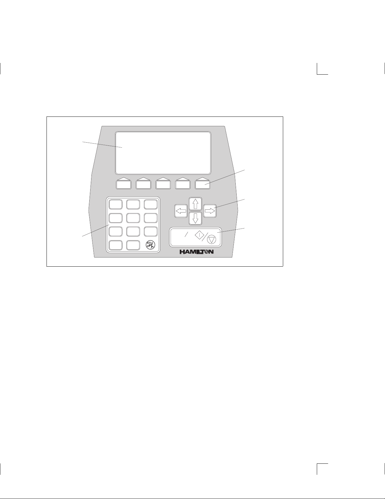
Figure 1–9 The Controller Unit
Display
Screen
12
56
4
89
Numeric
Keypad
7
0
.
Function
Keys
Arrows
3
Run
Stop
R
R
Keys
Run/Stop
Key
Chapter 1 Getting Started 1–17
Artisan Technology Group - Quality Instrumentation ... Guaranteed | (888) 88-SOURCE | www.artisantg.com
Page 40

Pipettors/Probes
Each MICROLAB 500B system comes with a remote push-button, hand-held
pipettor/probe. The standard accessory probes include:
• the Concorde Push-button Hand Pipettor/Probe (ships with MICROLAB 510B
and 530B; must be ordered separately for 500C models)
• the Dual Push-button Hand Pipettor/Probe (ships with MICROLAB 540B; must
order separately for the 541C model)
Additionally, three other optional probes may be ordered separately for use with
any MICROLAB 500 system. These probes include:
• the Disposable Tip Push-button Hand Pipettor/Probe
• the Luer Lock Tip Push-button Pipette Hand Pipettor/Probe
• the Viscous Sample Push-button Hand Pipettor/Probe
Concorde Push-button Hand Pipettor/Probe
The Concorde Push-button Hand Pipettor/Probe is a single-dispense pipette probe
that features a slim, comfortable design. Use this probe with MICROLAB 501 and
503 systems. The Concorde probe attaches directly to a sampling syringe or to the
valve assembly (output port). This probe accommodates both 12- or 18-gauge tubing
and features adjustable extension lengths beyond the probe tip. See Figure 1–10.
Dual Push-button Hand Pipettor/Probe
The Dual Push-button Hand Pipette Probe is a dual-dispense pipette that features
a pistol grip design with push-button actuator. Use this probe with MICROLAB 504
systems. This probe accommodates both 12- and 18-gauge tapered tubing lines with
independent extensions. You can extend the tubing out the end of the probe to the
length that is convenient for your application; either the right-side or the left-side
tubing can be extended to pick up sample. Figure 1–10 shows the Dual Push-button
Hand Pipette Probe.
1–18 MICROLAB 510B/511C, 530B/531C, and 540B/541C User’s Manual
Artisan Technology Group - Quality Instrumentation ... Guaranteed | (888) 88-SOURCE | www.artisantg.com
Page 41

Disposable Tip Push-button Hand Pipettor/Probes
The Disposable Tip Push-button Hand Pipette Probe is a single-dispense tube
pipette that features disposable tips and push-button tip ejection. The Disposable
Tip Push-button Hand Pipette Pipettor/Probe is an optional accessory. Use this
probe when sample-to-sample carryover is a concern. See Figure 1–10.
Figure 1–10 shows the Concorde, the Disposable Tip, and the Dual Hand
Pipettor/Probe.
Figure 1–10 The Concorde, the Disposable Tip, and the Dual Hand
Pipettor/Probes
Concorde
Pipettor
Probe
Disposable Tip
Pipettor
Probe
Dual Hand
Pipettor
Probe
Luer Lock Tip Push-button Pipette Hand Pipettor/Probe
The Luer Lock Tip Push-button Pipette Hand Pipettor/Probe is an optional
accessory that dispenses liquids through needles of different lengths and gauges.
This probe is useful for controlling very small dispense volumes with a high degree
of accuracy. It is also ideal for administering injections to small animals and for
piercing septa.
Chapter 1 Getting Started 1–19
Artisan Technology Group - Quality Instrumentation ... Guaranteed | (888) 88-SOURCE | www.artisantg.com
Page 42

Viscous Sample Push-button Hand Pipette Pipettor/Probe
The Viscous Sample Push-button Hand Pipettor/Probe is an optional accessory.
This single-dispense tube pipette is designed to accommodate highly viscous
samples, such as motor oil. This accessory features a disposable 5 mL tip that
eliminates sample carryover. Air displacement ensures accurate dilutions.
Footswitch
In addition to the hand-activated probes, a footswitch is also available. The
footswitch allows you to operate the MICROLAB 500 via a foot-activated control
pedal. This is useful when you need to keep both hands free, as when doing handsampling.
Refer to Appendix C for information about ordering the footswitch or any other
optional accessories.
Probe Button Functions
The probe button (on any model of hand probe) serves basically the same function as
the Run/Stop key on the controller unit. However, you cannot use the probe button to
pause an operation or to reinitialize the system after an error occurs.
1–20 MICROLAB 510B/511C, 530B/531C, and 540B/541C User’s Manual
Artisan Technology Group - Quality Instrumentation ... Guaranteed | (888) 88-SOURCE | www.artisantg.com
Page 43

Chapter 2 Installing the MICROLAB 500
System
This chapter contains information about installing the
MICROLAB 500 system, including the following topics:
• an overview of installation procedures
• selecting an installation location
• installing the accessory holder
• determining communications settings
• installing electrical connections
• installing the valve assembly
• selecting, installing , and removing syringes
• selecting and installing tubing
▲ Important Be sure to read the instructions in this chapter before
installing your MICROLAB system.
• Never install or use syringes incorrectly. Incorrect use
may result in damage to the syringes. See “Selecting,
Installing, and Removing Syringes” later in this chapter
for more information.
• Never over-tighten tubing. Over-tightening may result in
damage to the valves or tubing. See “Selecting and
Installing Tubing” later in this chapter for more
information.
• Call Hamilton Company’s Technical/Customer Service
Department at (800) 648–5950 (in the United States and
Canada) if you have questions about installing your
MICROLAB 500 system.
▲
2–1
Artisan Technology Group - Quality Instrumentation ... Guaranteed | (888) 88-SOURCE | www.artisantg.com
Page 44

Figure 2–1 Overview of Installation Procedures
Unpack the instrument;
check all parts against packing list
Select an installation location
Install the accessory holder
Determine the communications settings
Plug in electrical connections:
• power cord • hand probe
• controller unit cord
• alternate communications cords
Install the valve assembly
OR
Select
syringe
sizes
Install syringe(s)
Select
tubing
sizes
Install the fill tubing
Install the tubing clip
Install the dispense tubing
Run the dispense tubing through the hand probe
Fill out and return warranty card
Installation
is complete
2–2 MICROLAB 510B/511C, 530B/531C, and 540B/541C User’s Manual
Artisan Technology Group - Quality Instrumentation ... Guaranteed | (888) 88-SOURCE | www.artisantg.com
Page 45

Overview of Installation Procedures
Figure 2–1 provides an overview of the MICROLAB 500B installation procedures.
These procedures are described in detail in this chapter.
Selecting a Location
Install your MICROLAB 500 system in a clean, dry, level area away from
hazardous fumes. Leave space around the unit for ventilation; three inches is
sufficient.
Installing the Accessory Holder
All MICROLAB systems come with an accessory holder. You can mount the
accessory holder on either the right or the left side of the instrument. Generally,
the accessory holder is mounted on the right side and is used to hold a hand probe
when the probe is not in use. To install the accessory holder, follow these steps:
1. Locate the threaded holes on either the right or the left side of the instrument.
2. Use a hex wrench and screws (screws are provided) to attach the holder.
Chapter 2 Installing the MICROLAB 500 System 2–3
Artisan Technology Group - Quality Instrumentation ... Guaranteed | (888) 88-SOURCE | www.artisantg.com
Page 46

Selecting Communications Options
To select communications options, you must first decide how you will use the
instrument. That is, will it be a used as standalone device or will it be on a daisy
chain? Based on its use, select the appropriate communications settings. See Figure
2–2 for the location of the communication switches and ports. Table 2–1 describes
the purposes of these switches and ports.
To change a switch’s position, power the instrument off. Then use a screwdriver to
change the switch position. The small bump on the switch indicates the selected
position. After you change a switch’s position, power the instrument back on again.
Table 2–1 Communications Switches and Ports
Icon Item Purpose Possible Settings and Uses
TTL
A
RS-232 IN
receptacle
RS-232
OUT
receptacle
TTL port allows peripheral
controller or RS232 three possible uses:
handles outgoing
communications
devices to attach to
the drive unit
1. controller via coiled cord
2. connects to the communications
port on a PC
3. if on a daisy chain, connects to
the RS232 OUT port of the
previous unit on the chain
two possible uses:
1. if not on a daisy chain, is left
open
2. if on a daisy chain, connects to
the RS232 IN port of the next
chained device; is left open if it
is the last unit on the chain
attach digitally-controlled
devices such as pumps, monitors,
etc.; is left open if no peripherals
are attached
2–4 MICROLAB 510B/511C, 530B/531C, and 540B/541C User’s Manual
Artisan Technology Group - Quality Instrumentation ... Guaranteed | (888) 88-SOURCE | www.artisantg.com
Page 47

Table 2–1 Communications Switches and Ports
Icon Item Purpose Possible Settings and Uses
(continued)
BAUD
A
UNIT #
A
Loopback
switch
Baud
Rate
switch
Protocol
switch
allows the drive
unit to daisy-chain
to other units
controls the speed
at which the drive
unit communicates
with other devices
baud rate on the
controller unit must
match the baud rate
on the drive unit at
startup time; the
default is 9600
determines the
hardware address
and protocol of the
drive unit; the
default is Protocol 1
(position 0)
two possibilities:
1. UP: indicates the unit is a
standalone unit OR the last
item on a daisy chain
2. DOWN: indicates the unit is a
member of a daisy chain, in any
position except the last position
six possibilities:
0 = 1200
1 = 2400
2 = 4800
3 = 9600 (system default value)
4 = 19200
5 = 38400
6 = Unused
7 = Unused
8 = Unused
9 = Unused
two possibilities:
0 = Protocol 1/RNO+Syntax
(system default value)
• maximum items on a chain is 16
1–F = DIN Protocol
• if the drive unit is a member of a
daisy chain then each member
of the chain must have its own
unique address
• hardware address may/may
not be out of sequence
• maximum items on a chain is 15
Chapter 2 Installing the MICROLAB 500 System 2–5
Artisan Technology Group - Quality Instrumentation ... Guaranteed | (888) 88-SOURCE | www.artisantg.com
Page 48

Refer to Appendix E, RS-232 Communications with Manual ASCII Commands, and
Appendix F, Protocols, for more detailed information about MICROLAB 500 system
communications. Refer to Chapter 3, Programming and Using the MICROLAB 500
System, for more information about baud rate settings.
Installing Electrical Connections
A Warning! Always make sure that the instrument is powered off
before installing or removing any electrical
connections.
Refer to Figure 2–2 and follow these steps to install electrical connections:
1. Plug the power cord into the power connector receptacle on the back of the drive
unit. The power cord fits into the receptacle only one way.
The power connector receptacle accepts cords for either 115V or 220V.
2. Plug the hand probe (or foot pedal) jack into the probe connector receptacle. The
probe connector receptacle is located on the upper right side of the drive unit.
3. The controller connector receptacle is located on the back of the drive unit below
the serial number plate.
A
If you will be using the controller unit to communicate to the base unit, plug the
controller cord into the receptacle just as you plug a telephone cord into a
telephone outlet. Pinch the plastic locking device on the cord and insert it into
the connector receptacle. Then release the plastic locking device, firmly
attaching the cord.
4. If you will be using the drive unit to communicate to other devices, attach the
appropriate cords.
– To use the drive unit on a daisy chain, do not install the controller unit.
Instead, install the interconnect cord (Part # 35833) and connect it to the
RS-232 IN receptacle of the next device on the daisy chain. Leave
the RS-232 OUT receptacle open if the drive unit is the last unit on the
daisy chain.
2–6 MICROLAB 510B/511C, 530B/531C, and 540B/541C User’s Manual
Artisan Technology Group - Quality Instrumentation ... Guaranteed | (888) 88-SOURCE | www.artisantg.com
Page 49
For more information about possible communications options, refer to Table 2–1,
Communications Switches and Ports.
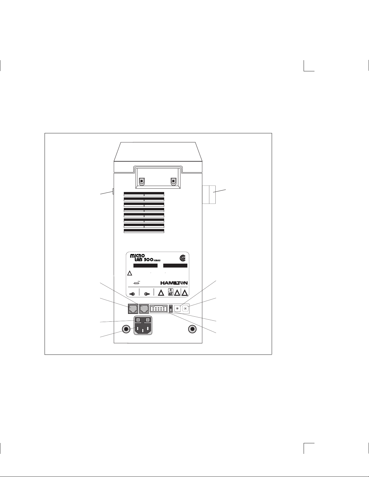
Figure 2–2 Installing Electrical Connections
Hand Probe
Connector
Receptacle
RS-232 OUT
Receptacle
Controller Unit
Connector
Receptacle
(RS-232 IN)
Fuse Box
Power Cord
Connector
Receptacle
R
RS-232
OUT
PART
NO.
MANUFACTURED BY
TTL
!
SERIAL
NO.
WARNING: DISCONNECT SUPPLY BEFORE SERVICING.
HIGH LEAKAGE CURRENT-ENSURE PROPER GROUNDING.
AVERTISSEMENT: COUPER LALIMENTATION AVANT L ENTRETIEN ET DEPANNAGE.
!
COURANT DEFUITE ELEVE-FOURNIER UNE MISE A LA TERRE EFFICACE.
WARNUNG: FUER SERVICEARBEITEN STROMZUFUHR UNTERBRECHEN.
HOHER LECKSTROM-GUTER ERDUNGSANSCHLUSS GEWAEHRLEISTEN.
100-240 V 50-60 HZ 150 VA
FUSE: T 1A/250 V
LABEL NO. 10650
RS-232
IN
LR-52122
RENO, NEVADA
BAUD
!
6
5
7
4
8
3
9
2
0
1
R
UNIT #
!
8
7
6
5
4
3
2
1
Accessory
Holder
R
Baud Rate
Switch
Protocol
9
A
B
C
D
E
F
0
Switch
Loopback
Switch
TTL Port
Chapter 2 Installing the MICROLAB 500 System 2–7
Artisan Technology Group - Quality Instrumentation ... Guaranteed | (888) 88-SOURCE | www.artisantg.com
Page 50
Installing Valve Assemblies
R
R
There are three types of valve assemblies for the MICROLAB 500 series.
Instructions for installing valve assemblies follow.
Installing the Valve Assembly on the MICROLAB 510B/511C
The MICROLAB 510B/511C uses a single active valve assembly. To install the
valve assembly, follow these steps:
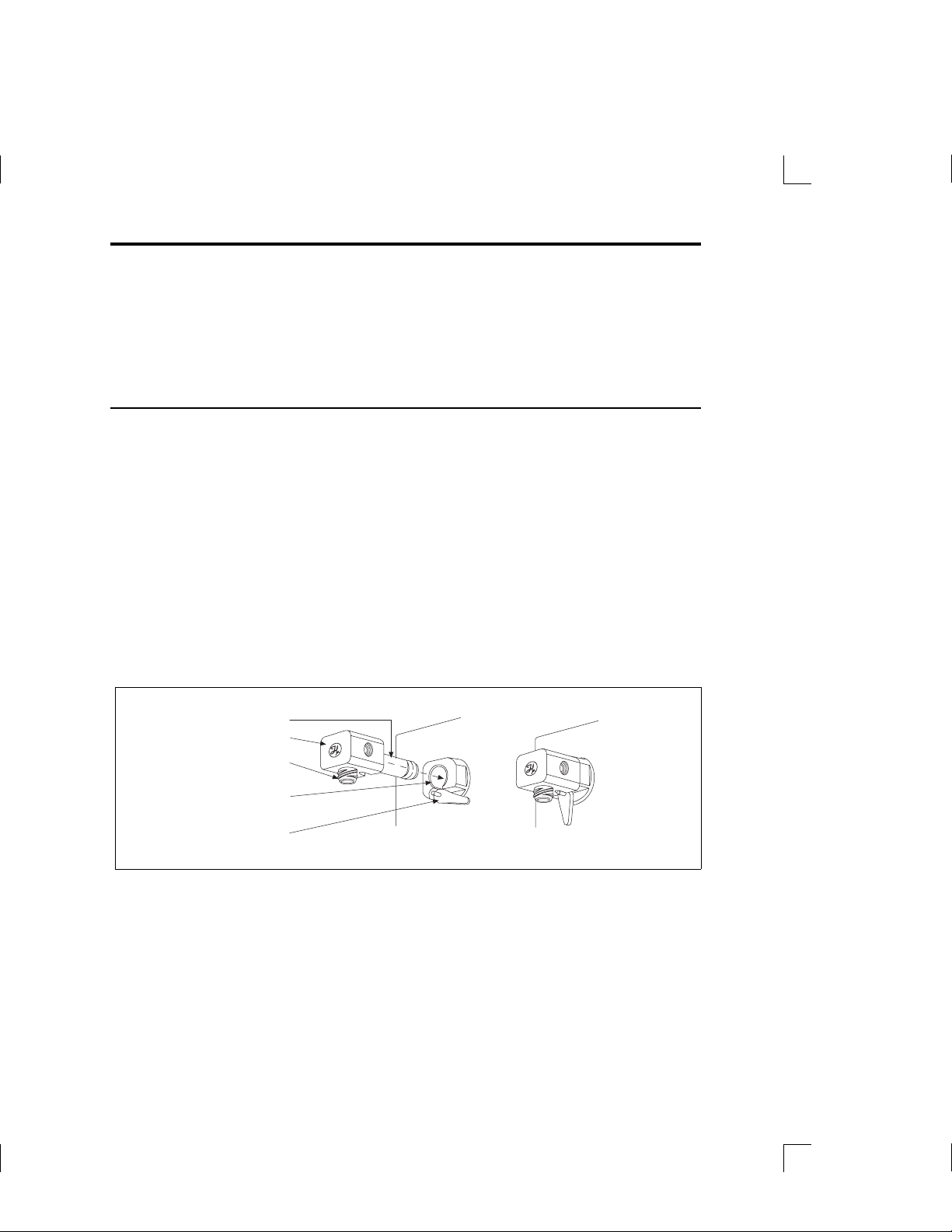
1. Pick up the valve assembly. Make sure the PTFE luer fitting that attaches
to the syringe is on the bottom of the assembly.
2. Holding the valve assembly, align the valve stem opening with the valve
motor drive port on the drive unit. Press the valve assembly into place.
3. Push down on the valve lever to lock the valve assembly to the drive unit.
Figure 2–3 Installing a Valve Assembly on the MICROLAB 510B/511C
Valve Stem
Valve
PTFE
Luer Fitting
Valve Motor
Drive Port
Valve Lever
Lock
2–8 MICROLAB 510B/511C, 530B/531C, and 540B/541C User’s Manual
Artisan Technology Group - Quality Instrumentation ... Guaranteed | (888) 88-SOURCE | www.artisantg.com
Page 51

Installing Valve Assemblies on the MICROLAB 530B/531C
and 540B/541C
Although the valve assemblies for the 530B/531C and 540B/541C units are
different from one another, their installation procedures are the same. To install a
valve assembly on either the MICROLAB 530B or 540B, follow these steps:
1. Pick up the valve assembly. Make sure the PTFE luer fittings that attach to
the syringes are on the bottom of the assembly.
2. Insert the valve assembly into the valve motor drive ports and press the valve
assembly into place.
3. Tighten the thumbscrew until it is finger-tight to secure the valve assembly to
the drive unit.
Figure 2–4 Installing a Valve Assembly on the MICROLAB 530B/531C and
540B/541C
Valve Motor
Drive Ports
Valve Stem
Valve
Thumbscrew
Chapter 2 Installing the MICROLAB 500 System 2–9
Artisan Technology Group - Quality Instrumentation ... Guaranteed | (888) 88-SOURCE | www.artisantg.com
Page 52

Selecting, Installing, and Removing Syringes
Before you install syringes on any MICROLAB instrument, you must first decide
what syringes to use. Use Tables 2–2 and 2– 3 to select the best syringe for your
application. See Figures 2–5 through 2–7 for examples of different syringe types.
• The MICROLAB 510B/511C uses one dispenser/diluent-type syringe in the left
position (TLL-type or TLLX-type syringes).
• The MICROLAB 540B/541C uses two dispenser/diluent-type syringes—one
each in the left and right positions (TLL or TLLX).
• The MICROLAB 530B/531C uses one reagent/diluent syringe in the left position
and one sample syringe in the right position (DX, TLL, or TLLX).
• As a general rule, to ensure high accuracy and precision, try to use 10% or more
of a syringe’s total volume. Consider using a different size syringe if your
application calls for driving a syringe less than 10% of its total volume, and
high accuracy and precision are required.
Table 2–2 Reagent/Diluent Syringes (TLL- and TLLX-types)
Syringe Sizes Model Number Part Number Optimal Ranges
(µL)
25 µL 1702 TLLX 80222 2.5–25
50 µL 1705 TLLX 80922 5–50
100 µL 1710 TLLX 81022 10–100
250 µL 1725 TLLX 81122 25–250
500 µL 1750 TLLX 81222 50–500
1 m L 1001 TLLX 81323 100–1000
2.5 mL 1002 TLL 81420 250–2500
5 m L 1005 TLL 81520 500–5000
10 m L 1010 TLL 81620 1000–10,000
25 m L 1025 TLL 82521 2500–25,000
2–10 MICROLAB 510B/511C, 530B/531C, and 540B/541C User’s Manual
Artisan Technology Group - Quality Instrumentation ... Guaranteed | (888) 88-SOURCE | www.artisantg.com
Page 53

Table 2–3 Sample Syringes (DX-type)
Syringe Sizes Model Number Part Number Optimal Ranges
(µL)
25 µL 1702 DX 80226 2.5–25
50 µL 1705 DX 80926 5–50
100 µL 1710 DX 81026 10–100
250 µL 1725 DX 81126 25–250
500 µL 1750 DX 81226 50–500
1 m L 1001 DX 81326 100–1000
See Appendix C for information regarding replacement parts for TLL, TLLX, and
DX syringes.
Figure 2–5 The TLL-type Dispenser/Diluent Syringe
Figure 2–6 The TLLX-type Dispenser/Diluent Syringe
Figure 2–7 The DX-type Sample Syringe
Chapter 2 Installing the MICROLAB 500 System 2–11
Artisan Technology Group - Quality Instrumentation ... Guaranteed | (888) 88-SOURCE | www.artisantg.com
Page 54

Preparing Syringes for Installation
When you unpack a new syringe, notice that the syringe plunger is packed
separately from the syringe barrel. You must condition the plunger tip before
inserting the plunger into the barrel.
▲ Important Before using a new syringe for the first time, you
must condition the syringe’s PTFE plunger tip and
glass barrel. To condition the tip and barrel, wet the
plunger tip with distilled water or a solvent. (Medicaltype silicone lubricants may be used to extend the
lives of PTFE plunger tips. However, silicone may
contaminate the process fluid.) Do NOT use viscous
oils to lubricate plunger tips.
After wetting the plunger tip, insert the plunger into
the glass barrel. Move the plunger in and out of the
glass barrel approximately 10 times. Apply steady
and even pressure; avoid twisting movements.
▲
Installing Syringes
Follow these steps to install syringes on any MICROLAB 500 system.
1. Condition all syringes before installation by following the procedure described
in “Preparing Syringes for Installation.”
2. Power on the MICROLAB system using the Power On/Off switch.
3. Press and hold the Step/Prime switch in the Step position, and move the
syringe drive arm down from the Home position. Release the switch when the
drive arm is about half-way between Home and the Down position.
2–12 MICROLAB 510B/511C, 530B/531C, and 540B/541C User’s Manual
Artisan Technology Group - Quality Instrumentation ... Guaranteed | (888) 88-SOURCE | www.artisantg.com
Page 55

4. Fasten the thumbscrew on the drive arm to the bottom of the syringe plunger. To
fasten the thumbscrew, hold the plunger and screw the thumbscrew into the
threaded fitting at the bottom of the syringe.
5. Pull the glass barrel up straight to the threaded female luer fitting that
extends down from the bottom of the valve. Insert the male luer fitting into the
valve fitting and turn the glass barrel clockwise until it is “finger-tight.”
See Figure 2–8, Installing a Syringe, for an illustration of these steps.
Figure 2–8 Installing a Syringe
Then, mount the Luer
First, mount the
Lock.
Thumbscrew.
Chapter 2 Installing the MICROLAB 500 System 2–13
Artisan Technology Group - Quality Instrumentation ... Guaranteed | (888) 88-SOURCE | www.artisantg.com
Page 56

▲ Important Always tighten syringes so they are “finger-tight.”
Syringes that are over- or under-tightened can cause
problems for your MICROLAB 500 system.
• Syringes that are over-tightened may cause leaks
or may damage the valve.
• Syringes that are under-tightened may cause
leaks.
• Syringes that are not screwed on straight may leak
and cause lateral strain on the syringe luer fitting
as it connects to the bottom of the valve.
▲
Removing Syringes
To remove syringes, reverse the installation procedure.
1. Power on the system using the Power On/Off switch.
2. Use the Step/Prime switch to move the syringe drive arm down from the Home
position. Release the switch when the drive arm is about half way between
Home and the Down position.
▲ Important Before you use the Prime function, direct the probe
toward a liquid waste container or reservoir since
initialization may expel any fluid remaining in the
syringes.
3. Release the glass barrel by turning it counterclockwise.
4. Unfasten the thumbscrew on the drive arm at the bottom of the syringe plunger.
To unfasten the thumbscrew, hold the plunger and unscrew the thumbscrew from
the threaded fitting at the bottom of the syringe.
Refer to Figure 2–9, Removing a Syringe, for an illustration of the removal
procedure.
2–14 MICROLAB 510B/511C, 530B/531C, and 540B/541C User’s Manual
Artisan Technology Group - Quality Instrumentation ... Guaranteed | (888) 88-SOURCE | www.artisantg.com
▲
Page 57

Figure 2–9 Removing a Syringe
First, remove the
Luer Lock
Then, remove the
Thumbscrew.
A
Warning! Avoid the risk of injury or infection! Use extreme
caution when removing cracked or splintered
syringes. Always wear thick gloves and protective
eye wear when replacing syringes.
Chapter 2 Installing the MICROLAB 500 System 2–15
A
Artisan Technology Group - Quality Instrumentation ... Guaranteed | (888) 88-SOURCE | www.artisantg.com
Page 58

Selecting and Installing Tubing
This section provides information about selecting and installing tubing on all
MICROLAB 500 systems.
Selecting Tubing
Each MICROLAB system includes two gauges of fill and dispense tubing: 12- and 18gauge. Fill tubing has a 90˚ cut on the end opposite the fitting; dispense tubing has a
tapered end opposite the fitting.
When selecting tubing, consider the volume and the viscosity of the liquid you plan
to pipette. Refer to Table 2–3, Tubing Selection Guide, for help in selecting tubing.
Table 2–4 Tubing Selection Guide
Syringe
Size
Tubing Gauge for
Standard Aqueous
Solutions
Tubing Gauge for
Viscous and
Foaming Liquids
25 µL18 18
50 µL18 18
100 µL18 18
250 µL18 18
500 µL18 18
1 mL 18 18
2.5 mL 18 12
5 mL 12 12
10 mL 12 12
25 mL 12 12
2–16 MICROLAB 510B/511C, 530B/531C, and 540B/541C User’s Manual
Artisan Technology Group - Quality Instrumentation ... Guaranteed | (888) 88-SOURCE | www.artisantg.com
Page 59

✱ Note: If you have a MICROLAB 530B/531C diluter and plan to use
syringes of two different sizes, choose tubing to accommodate the
syringe with the larger volume. ✱
See Appendix C for information about ordering extra tubing.
Installing Tubing
1. Before installing tubing lines, wet the tubing fittings.
2. Make sure the tubing lines do not contain crimps or blockages. Crimps or
blockages can cause leaks or can cause the system to overload. If tubing is
crimped, replace it with new tubing.
▲ Important Fasten tubing so it is finger-tight and snug enough to
prevent leaks. Avoid using tools to tighten tubing.
Excessive tightening may damage tubing, valve
fittings, or flanges.
3. Install the fill tubing. You can differentiate fill tubing and dispense tubing since
dispense tubing has a tapered end.
▲
– For all MICROLAB 500 models, install the fill tubing on the left, or input
side of the valve. Thread the tubing fitting into the left valve port, and
screw it in so it is finger-tight.
– For the MICROLAB 540B/541C only, install a second fill tubing line on the
right side of the valve. Thread the tubing fitting into the right valve port,
and screw it in so it is finger-tight, just as you did on the right side.
4. Once the fill tubing is installed, attach a tubing clip to it. Slip the tubing clip
over the end of the tubing, then attach the clip to the side of the reservoir.
Chapter 2 Installing the MICROLAB 500 System 2–17
Artisan Technology Group - Quality Instrumentation ... Guaranteed | (888) 88-SOURCE | www.artisantg.com
Page 60

5. Install the dispense tubing. You can recognize dispense tubing by its tapered end.
– If you are using a MICROLAB 510B/511C, install the dispense tubing on the
right side of the valve. Thread the tubing fitting into the right valve port
and screw it in so it is finger-tight. See Figure 2–10 for an illustration of the
valve and tubing connectors.
Figure 2–10 MICROLAB 510B/511C Valve and Tubing Connections
R
Input Side
(Port)
Output Side
(Port)
– If you are using a MICROLAB 530B/531C with a D syringe, install the
dispense tubing on the side port of the D syringe. See Figure 2–11. When
using a TLL syringe as a sampling syringe, install dispense tubing directly
onto the valve assembly. To do this, remove the valve plug and replace the
plug with dispense tubing. See Figure 2–12.
2–18 MICROLAB 510B/511C, 530B/531C, and 540B/541C User’s Manual
Artisan Technology Group - Quality Instrumentation ... Guaranteed | (888) 88-SOURCE | www.artisantg.com
Page 61

Figure 2–11 MICROLAB 530B/531C Valve with a D Configuration Syringe
Insert Valve
Plug First
Input Side
(Port)
Output Side
(Port)
Figure 2–12 MICROLAB 530B/531C Valve with Two TLLX or TLL Syringes
Remove Valve
Plug First
Input Side
(Port)
Output Side
(Port)
Chapter 2 Installing the MICROLAB 500 System 2–19
Artisan Technology Group - Quality Instrumentation ... Guaranteed | (888) 88-SOURCE | www.artisantg.com
Page 62

– If you are using a MICROLAB 540B/541C, install a tapered dispense tubing
line into each of the valve’s front ports. The front ports are located on the
bottom of the valve between the two syringes. Thread the tubing fittings
into the front ports, and screw the fittings in so they are finger-tight. See
Figure 2–13.
Figure 2–13 MICROLAB 540B/541C Valve and Tubing Connectors
Input Side
(Port)
Input Side
(Port)
Output Ports
✽ Note: It is possible to use the 540B/541C dual dispenser as a single
dispenser. When programming, designate the instrument as a single
dispenser.
6. Install the dispense tubing to the hand probe.
– If you are using the MICROLAB 510B or the MICROLAB 530B, the
Concorde Probe comes as standard equipment. This probe uses a single
dispense tube. To attach the dispense tubing into the probe, loosen the
knurled screw at the upper end of the probe. Slide the tapered end of the
dispense tube through the probe so that the tubing passes out the end of the
probe. When enough tubing for you to work with extends from the probe,
tighten the knurled screw to secure the tubing line.
2–20 MICROLAB 510B/511C, 530B/531C, and 540B/541C User’s Manual
✽
Artisan Technology Group - Quality Instrumentation ... Guaranteed | (888) 88-SOURCE | www.artisantg.com
Page 63

– If you are using the MICROLAB 540B, the Dual Hand Probe comes as
standard equipment. This probe is designed for both 18- and 12-gauge
tubing. Use the tubing reducer (Part # 35770) that is provided with the dual
hand probe if you wish to use 18-gauge tubing. See Figure 2–14.
Figure 2–14 Using the Tubing Reducer with the Dual Hand Probe
7. Fill out the warranty card and return it to Hamilton Company.
8. You are now ready to use your MICROLAB 500 system.
Chapter 2 Installing the MICROLAB 500 System 2–21
Artisan Technology Group - Quality Instrumentation ... Guaranteed | (888) 88-SOURCE | www.artisantg.com
Page 64

Artisan Technology Group - Quality Instrumentation ... Guaranteed | (888) 88-SOURCE | www.artisantg.com
Page 65

Chapter 3 Programming and Using the
MICROLAB 500B System
This chapter contains information about the following topics:
• an overview of the MICROLAB 500 functions
• using the controller unit keys
• accessing the Main menu
• priming and checking the system
• creating methods
• running methods
• using the Utility menu functions
For information on controlling 500C systems, refer to Appendixes
E and F.
Figure 3–1 Using the MICROLAB 500B
Power up the instrument
Prime the instrument
Select a function
from the Main menu
Follow the on-screen instructions
Finished
using the
instrument?
Yes
When finished, flush the fluid line
and turn the instrument off
No
Select
another
function
3–1
Artisan Technology Group - Quality Instrumentation ... Guaranteed | (888) 88-SOURCE | www.artisantg.com
Page 66
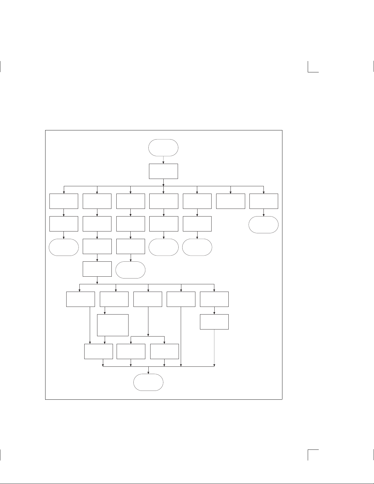
Figure 3–2 provides an overview of the functions available using the MICROLAB
500B. These functions are described in detail later in this chapter.
Figure 3–2 Overview of MICROLAB 500B Functions
Power up/
startup
screen
Main
menu
Run
existing
method
Select
method
Run
Pipette Dilute
Create
new
method
Name
Instrument
configuration:
single/dual
Select
method type
to create
Set:
• Gap
• Speed
• # of Syringes
Wash?
Edit
existing
method
Select
method
Edit
Save and
return to
Main menu
Aliquot
configuration:
Dispense
Manual
dilute
Instrument
single/dual
Run Run
Titrate
Serial
Manual
dispense
Instrument
configuration:
single/dual
Custom
Write
method
UtilitiesPrime
See
Utilities menu
flowchart
Save and
return to
Main menu
3–2 MICROLAB 510B/511C, 530B/531C, and 540B/541C User’s Manual
Artisan Technology Group - Quality Instrumentation ... Guaranteed | (888) 88-SOURCE | www.artisantg.com
Page 67
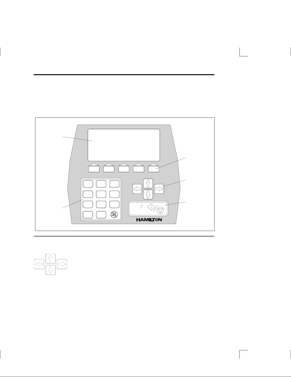
Using the Controller Unit
Use the controller unit to create and run methods, to enter and change data, and to
perform utility functions. Figure 3–3 shows the controller unit.
Figure 3–3 The Controller Unit
Display
Screen
Function
Keys
Arrows
Keys
Run/Stop
Key
Numeric
Keypad
12
56
4
89
7
0
.
3
Run
Stop
R
R
Using the Arrow Keys
The arrow keys are located on right side of the controller unit,
between the function keys and the Run/Stop key. Use the arrow
keys to move from one data entry field to another on the display
screen; each key moves you in the direction that it points. The
current field is highlighted in reverse video on the display
screen. In this manual, items are highlighted with boldface text.
Artisan Technology Group - Quality Instrumentation ... Guaranteed | (888) 88-SOURCE | www.artisantg.com
Chapter 3 Using the MICROLAB 500 System 3–3
Page 68
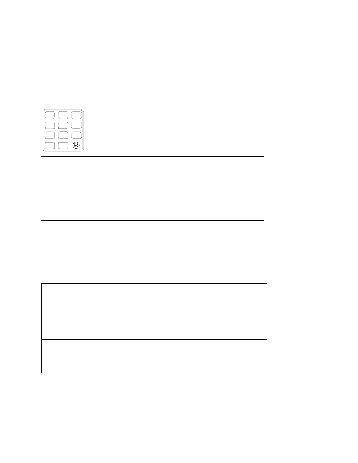
Using the Numeric Keypad
The numeric keypad is located in the lower left corner of the
12
4
7
.
3
56
89
R
0
controller unit. Use the numeric keypad to enter numeric data
when using the edit mode (see “Editing Conventions” for
information about the edit mode).
Using the Run/Stop Key
The Run/Stop key is located in the bottom right corner of the
E
controller unit. This key generates a command signal that
activates the next step or pauses the unit during a method. You
can also generate a start signal by pressing the button on a hand
probe or by using a footswitch.
Using the Function Keys
The function keys are located directly below the display screen. Use these keys to
perform specific actions, based on the requirements of the current screen. To perform
an action, press the function key located beneath the action. Not all actions are
available from all screens.
Table 3–1 Function Key Actions
SELECT selects the highlighted element on the screen so it can be edited or
acted upon in some manner
ESCAPE returns you to the previous screen without saving any changes; also
abandons the current edit mode process
ACCEPT accepts the displayed screen with any changes
CONFIRM verifies that you want to save your changes or that you want to
perform an action
DELETE deletes the highlighted element on the screen
ENTER accepts the underlined value entered while in edit mode
MODE allows you to choose the next operation to be performed in a manual
method
3–4 MICROLAB 510B/511C, 530B/531C, and 540B/541C User’s Manual
Artisan Technology Group - Quality Instrumentation ... Guaranteed | (888) 88-SOURCE | www.artisantg.com
Page 69

Editing Conventions
To use the edit mode, press the appropriate arrow key to move to the desired screen
location. Then press the SELECT function key; you must always press SELECT before
you can change the value of any highlighted item. For example, to enter a size for a
syringe, use an arrow key to move to and highlight the syringe size field.
Instrument configuration
One syringe instrument
Two syringe instrument
Left Syringe size (uL): 1000.0
Right Syringe size (uL): 1000.0
SELECT item to edit-ACCEPT if complete
SELECT ESCAPE ACCEPT
When you press SELECT, notice that the highlighting changes to underlining. Now
you can edit the underlined value; instructions for data entry appear near the
bottom of the screen. Use the arrow keys (or in some cases, the numeric keypad
numbers), to increase or decrease the underlined value. When you are satisfied with
your entry, press ENTER.
Instrument configuration
One syringe instrument
Two syringe instrument
Left Syringe size (uL): 2000.0
Right Syringe size (uL): 1000.0
Use arrow keys to change syringe size
ENTER ESCAPE
Artisan Technology Group - Quality Instrumentation ... Guaranteed | (888) 88-SOURCE | www.artisantg.com
Chapter 3 Using the MICROLAB 500 System 3–5
Page 70

Pressing ENTER returns you to the previous screen, keeping the data entry change
you just made. When you are finished editing, press ACCEPT to use the values
displayed in all fields on the screen.
Instrument configuration
One syringe instrument
Two syringe instrument
Left Syringe size (uL): 2000.0
Right Syringe size (uL): 1000.0
SELECT item to edit-ACCEPT if complete
SELECT ESCAPE ACCEPT
Powering on the MICROLAB 500
To power on the MICROLAB 500, press the Power On/Off switch located on the
front panel of the drive unit. When the instrument powers up, it performs an
electronic self-test and beeps twice. The first time that you start up the instrument,
you see the following screen:
HAMILTBN
MICROLAB 500 Series
version #
3–6 MICROLAB 510B/511C, 530B/531C, and 540B/541C User’s Manual
Artisan Technology Group - Quality Instrumentation ... Guaranteed | (888) 88-SOURCE | www.artisantg.com
Page 71

Next, the “Change default language” screen appears:
Change default language
English
Francais
Deutsch
Português
Español
Clear default language
SELECT menu item
SELECT
Select a default language. The language that you select will become the system
default, and all future screens will appear in that language. You will not be
prompted again for a default language at startup. See “Changing the Default
Language” later in this chapter for more information.
The Main Menu
After you select a default language, the Main menu appears:
MICROLAB 500 main menu
Run an existing method
Create a new method
Edit an existing method
Manual dilution
Manual dispense
Prime the fluid path
Utilities menu
SELECT menu item
SELECT
Use the arrow keys to highlight the desired function. Then press SELECT.
Information about each of the Main menu functions follows in this chapter.
Chapter 3 Using the MICROLAB 500 System 3–7
Artisan Technology Group - Quality Instrumentation ... Guaranteed | (888) 88-SOURCE | www.artisantg.com
Page 72

Priming the MICROLAB 500
This section describes how to set up and prime the MICROLAB 500.
Preparing to Prime
Prime the MICROLAB 500 system before using it for the first time, at the start of a
work day, and between fluid changes. Run fluid through the tubing lines to ensure
that there are no bubbles or air gaps in the tubing. Check the fluid path for leaks
and clean the fluid path, if necessary.
To prime the MICROLAB 500 and check the fluid path for leaks, follow these
steps:
1. Fill a reservoir with deionized water. Place the end of the inlet tubing in
the reservoir. Use the tubing clip to attach the tubing to the side of the
reservoir.
2. Place the hand probe over the same reservoir or over a waste container.
3. Push the Prime switch on the drive unit OR select the Prime function from the
main menu. See the next section, Using the Prime function from the Main menu,
for more information.
4. Run the instrument in Prime mode until water flows through the entire system.
5. If the system is airtight, the fluid path will contain a solid column of water.
– If you see air bubbles in the fluid path, the system is not airtight. Adjust
the tubing fittings or syringes. Check that all parts are snug and fingertight.
– If you do not see air bubbles in the fluid path, the system is airtight.
3–8 MICROLAB 510B/511C, 530B/531C, and 540B/541C User’s Manual
Artisan Technology Group - Quality Instrumentation ... Guaranteed | (888) 88-SOURCE | www.artisantg.com
Page 73

6. If you do not see air bubbles in the fluid path, but small bubbles appear on the
PTFE surface of the syringe, clean the internal fluid path with a mild
syringe cleaner. Rinse with deionized water to rid the system of cleaning fluid.
To clean the fluid path, follow the steps in Chapter 4, Caring for the
MICROLAB 500.
7. After cleaning, reprime with deionized water to rinse the fluid path. Continue
priming until you do not see any bubbles.
8. Remove the inlet tubing from the reservoir and prime air through the system.
Priming air through the system clears the fluid path of the deionized water
that you used as a rinse.
9. When the fluid path is free of deionized water, place the inlet tubing into a
reservoir of the liquid you wish to dispense or use as a diluent. Prime this fluid
through the system.
✱ Note: When priming reagent after a deionized water rinse,
dispense the first shot into a waste container, since it will contain
a certain amount of the water droplets that remained in the tubing
line. ✱
10. Your MICROLAB 500 system is clean and ready for use.
▲ Important Do not operate either side dry, as this may cause
excessive wear on the syringes and valves.
Chapter 3 Using the MICROLAB 500 System 3–9
▲
Artisan Technology Group - Quality Instrumentation ... Guaranteed | (888) 88-SOURCE | www.artisantg.com
Page 74

Figure 3–4 shows the required steps for priming the instrument.
Figure 3–4 Priming the MICROLAB 500
select the Prime function from the Main menu
Press the Prime Switch OR
and start priming the instrument
Yes
1st time use?
Clean the
fluid path
No
Check the fluid path for leaks
Any leaks in
the fluid path?
Yes
Adjust
tubing,
fittings, and
syringes
No
Any bubbles
on the plunger
tip?
Yes
Clean the
fluid path
No
Halt the priming cycle
Finished
using the
instrument?
No
Select
another
function
Yes
When finished, flush the fluid line
and turn the instrument off
3–10 MICROLAB 510B/511C, 530B/531C, and 540B/541C User’s Manual
Artisan Technology Group - Quality Instrumentation ... Guaranteed | (888) 88-SOURCE | www.artisantg.com
Page 75

Using the Prime Function from the Main Menu
1. From the Main menu, SELECT the “Prime the fluid path” function. The
following screen appears:
Drive unit initialization
Any fluid in the syringes on the
drive unit will now be purged. Please
ensure the probe is directed towards a
waste area.
CONFIRM to continue, ESCAPE to exit
ESCAPE CONFIRM
▲ Important When you select the Prime method, the instrument
alerts you that the fluid in the syringes is about to be
purged. Be sure to place the probe over a fluid waste
area or a reservoir before pressing CONFIRM to
continue the priming function.
2. Press CONFIRM to continue the priming process.
3. The following screen appears:
▲
Prime the fluid path
Full Cycles: 10
Syringe prime speed: 4
SELECT item to edit-RUN to start
SELECT ESCAPE
– Enter the desired number of priming cycles; 10 is the default.
– Enter the prime speed. Speed must be in whole seconds, from 1 to 250.
– Press the Run/Stop key to start the priming cycle.
Chapter 3 Using the MICROLAB 500 System 3–11
Artisan Technology Group - Quality Instrumentation ... Guaranteed | (888) 88-SOURCE | www.artisantg.com
Page 76

4. The instrument displays the status of the priming cycle.
Prime the fluid path
Priming. . .
3 of 10 strokes completed.
STOP to pause
– Press the Run/Stop key to pause the priming cycle. If you pause the priming
cycle, you see the following screen:
Prime the fluid path
Priming. . .
3 of 10 strokes completed.
RUN to continue, ESCAPE to exit
ESCAPE
– Press the Run/Stop key once again to resume the cycle or press ESCAPE to
exit the cycle.
5. When the cycle is complete, the instrument displays a message stating that the
prime is complete. Press any key to return to the main menu.
Prime the fluid path
Priming. . .
10 of 10 strokes completed.
Prime complete
Press any key to continue
3–12 MICROLAB 510B/511C, 530B/531C, and 540B/541C User’s Manual
Artisan Technology Group - Quality Instrumentation ... Guaranteed | (888) 88-SOURCE | www.artisantg.com
Page 77

Creating a New Method
Use this function to create and save a new method in the method storage area. You
can create and save up to 21 methods. To create a new method, follow these steps:
1. From the main menu, use the arrow keys to highlight the “Create a new
method” function, then press SELECT.
2. The instrument displays the method storage area with an unused method
location already highlighted. Unused method locations are denoted by the
term “<UNUSED>”. If desired, use the arrow keys to move to another location.
Press SELECT to use a highlighted location or press ESCAPE to return to the
main menu without creating a new method.
Create a new method
<UNUSED> <UNUSED> <UNUSED>
<UNUSED> <UNUSED> <UNUSED>
<UNUSED> <UNUSED> <UNUSED>
<UNUSED> <UNUSED> <UNUSED>
<UNUSED> <UNUSED> <UNUSED>
<UNUSED> <UNUSED> <UNUSED>
<UNUSED> <UNUSED> <UNUSED>
SELECT an UNUSED method
SELECT ESCAPE
3. If you press SELECT, you access the following screen:
Create a new method
1 2 3 4 5 6 7 8 9 Q W E R T Y U I O P
A S D F G H J K L
Z X C V B N M
SPACE
Name:__________
SELECT next letter-ACCEPT if complete
SELECT ESCAPE ACCEPT DELETE
Chapter 3 Using the MICROLAB 500 System 3–13
Artisan Technology Group - Quality Instrumentation ... Guaranteed | (888) 88-SOURCE | www.artisantg.com
Page 78

Use the arrow keys to spell out the new method’s name, using up to 10
characters.
– To accept a character, press SELECT.
– To erase a character, press DELETE.
– Press ESCAPE to return to the main menu without creating a new method.
– Press ACCEPT when you are finished naming the new method.
4. Next, the instrument prompts you for the configuration you are using. Use the
arrow keys to highlight either a one- or a two-syringe instrument configuration.
Instrument configuration
One syringe instrument
Two syringe instrument
SELECT menu item
SELECT ESCAPE
– Press SELECT to accept the highlighted instrument configuration.
– Press ESCAPE to return to the previous screen without selecting an
instrument configuration.
5. Once you select an instrument configuration, you are prompted to enter syringe
size(s). For example, in the following screen the user has selected a two-syringe
instrument. The system supplies default syringe sizes.
3–14 MICROLAB 510B/511C, 530B/531C, and 540B/541C User’s Manual
Artisan Technology Group - Quality Instrumentation ... Guaranteed | (888) 88-SOURCE | www.artisantg.com
Page 79

Instrument configuration
One syringe instrument
Two syringe instrument
Left Syringe size (uL): 1000.0
Right Syringe size (uL): 1000.0
SELECT item to edit-ACCEPT if complete
SELECT ESCAPE ACCEPT
6. You can use the default values that are displayed, or you can enter new sizes. To
enter a new size, use the arrow keys to highlight the appropriate syringe, then
press SELECT. Notice that the highlighting changes to an underline, as shown
in the following screen:
Instrument configuration
One syringe instrument
Two syringe instrument
Left Syringe size (uL): 2500.0
Right Syringe size (uL): 1000.0
Use arrow keys to change syringe size
ENTER ESCAPE
Now, use the arrow keys to increase or decrease the syringe size. When you
have selected the correct size, press ENTER.
✱ Note: You must use the arrow keys to change syringe sizes. ✱
Chapter 3 Using the MICROLAB 500 System 3–15
Artisan Technology Group - Quality Instrumentation ... Guaranteed | (888) 88-SOURCE | www.artisantg.com
Page 80
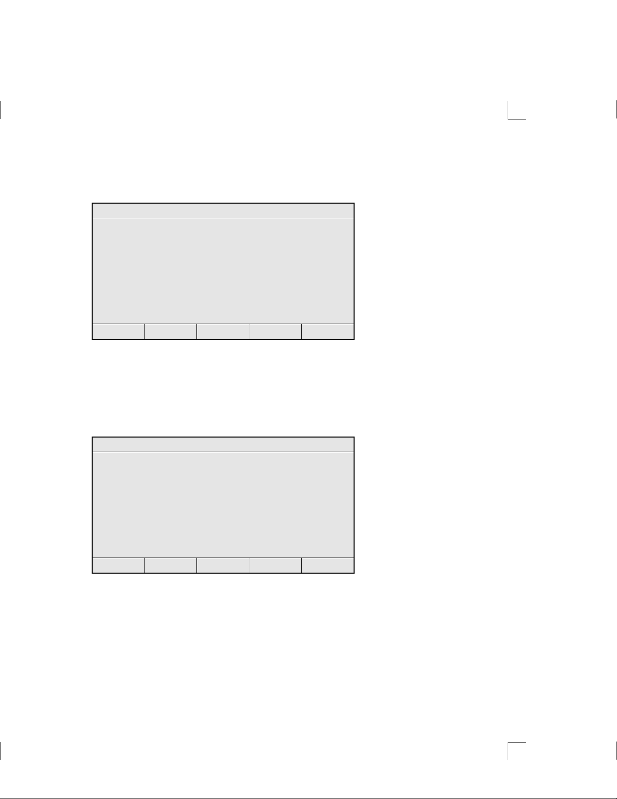
7. Press ACCEPT to accept all syringe size values shown on the screen. The
“Method type to create” menu appears:
Method type to create
Aliquot dispense method
Serial dispense method
Dilute method
Pipette method
Titrate method
Custom method
SELECT menu item
SELECT ESCAPE
8. SELECT a method type. Each individual method consists of a series of screens
and prompts that are described in detail. Refer to the following sections for
information about creating specific methods.
9. When you are finished creating a method, the “Save method in method
memory” screen appears. This screen shows the name of the new method.
Save method in method memory
Method: NEW1
will be stored in method memory.
CONFIRM to save, ESCAPE to cancel
ESCAPE CONFIRM
– Press CONFIRM to save the method, then press any key to continue.
– Press ESCAPE to return to the previous screen.
3–16 MICROLAB 510B/511C, 530B/531C, and 540B/541C User’s Manual
Artisan Technology Group - Quality Instrumentation ... Guaranteed | (888) 88-SOURCE | www.artisantg.com
Page 81

Creating an Aliquot Dispense Method
Use this function to create an aliquot dispense method. An aliquot dispense method
consecutively dispenses equal amounts of liquids.
1. Follow steps 1–8 under “Creating a New Method.” Select the “Aliquot dispense
method” function from the “Method type to create” menu. The “Aliquot
dispense parameters” screen appears:
Aliquot dispense parameters
Left Right
Aliquot volume (uL): 2500.0 250.0
Maximum aliquots: 1 1
Aliquots to dispense: 1
Syringe fill speed: 4 2
Syringe dispense speed: 4 2
Syringe fill mode: AUTO
SELECT item to edit-ACCEPT if complete
SELECT ESCAPE ACCEPT
2. Enter the volume(s) to be aliquoted. To enter a volume, use the arrow keys to
highlight the Aliquot volume field, then press SELECT. The highlighting
changes to underlining. Use the number keys to enter a new volume. When
satisfied with your entry, press ENTER. The underline disappears and the
highlighting reappears.
✱ Note: You cannot enter a value in the Maximum Aliquots field.
The system automatically calculates Maximum Aliquots:
Maximum Aliquots = Total volume / Aliquot volume ✱
3. Enter the number of aliquots to be dispensed. Note that this number cannot be
larger than the calculated number in the Maximum Aliquots field.
4. Enter the syringe fill speed.
5. Enter the syringe dispense speed.
Chapter 3 Using the MICROLAB 500 System 3–17
Artisan Technology Group - Quality Instrumentation ... Guaranteed | (888) 88-SOURCE | www.artisantg.com
Page 82

6. Enter the syringe fill mode; this mode can be either Auto or Manual. Use the
arrow keys to change the current mode.
– Auto mode means that the instrument will perform the fill function
automatically when you run the method.
– Manual mode means you must press the Run/Stop key or press the probe
button to activate the fill function when you run the method.
7. When you are satisfied with your entries, press ACCEPT. The instrument
displays the “Save method in method memory” screen. Press CONFIRM to save
the method, then press any key to continue.
Creating a Serial Dispense Method
Use this function to create a serial dispense method that serially dispenses various
amounts of liquids.
1. Follow steps 1–8 under “Creating a New Method.” Select the “Serial dispense
method” function from the “Method type to create” menu. The “Serial dispense
volumes” screen appears:
Serial dispense volumes (uL)
Left Used 2500.0 Right Used 250.0
Available 0.0 Available 0.0
1. 2500.0 250.0
2.
3.
4.
5.
SELECT item to edit-ACCEPT if complete
SELECT ESCAPE ACCEPT DELETE
2. Enter the volumes to be dispensed from the syringes. Notice that default values
to be dispensed are 100%, with the amount available 0%. As soon as you enter
an amount to be dispensed, the system recalculates the volume available.
3–18 MICROLAB 510B/511C, 530B/531C, and 540B/541C User’s Manual
Artisan Technology Group - Quality Instrumentation ... Guaranteed | (888) 88-SOURCE | www.artisantg.com
Page 83
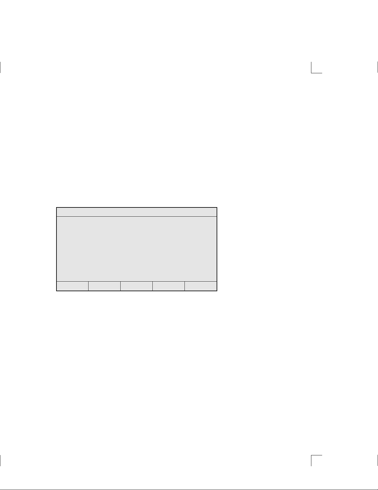
✱ Note: Notice that default value for the “Used” field is 100% of the
syringe size, and the default value for the “Available” field is 0%
of the syringe size. As enter amounts to be dispensed, the system
recalculates the volumes:
Used = Sum of all dispense amounts entered on all lines
Available = (Syringe size - Used) ✱
– Enter up to 20 command lines; the screen will scroll as you add lines. If you
enter more than 20 lines, you return to line one.
3. Press DELETE to delete an entry. Use the arrow keys to move about from line to
line. When you are finished entering amounts to be dispensed, press ACCEPT.
4. The system displays the “Serial dispense method parameters” screen:
Serial dispense method parameters
Dispenses: 1 Left Right
Fill volume (uL): 2500.0 250.0
Syringe fill speed: 4 2
Syringe dispense speed: 4 2
Syringe fill mode: AUTO
SELECT item to edit-ACCEPT if complete
SELECT ESCAPE ACCEPT
5. Enter syringe fill speeds.
6. Enter syringe dispense speeds.
7. Select a syringe fill mode. Valid modes are AUTO or MANUAL.
– Auto mode means that the instrument will perform the fill function
automatically when you run the method.
– Manual mode means you must press the Run/Stop key or press the probe
button to activate the fill function when you run the method.
8. When you are satisfied with your entries, press ACCEPT. The system displays
the “Save method in method memory” screen. Press CONFIRM to save the
method, then press any key to continue.
Chapter 3 Using the MICROLAB 500 System 3–19
Artisan Technology Group - Quality Instrumentation ... Guaranteed | (888) 88-SOURCE | www.artisantg.com
Page 84

Creating a Dilution Method
Use this function to create a dilution method to perform the following tasks:
• Fill the diluent syringe (if using a two-syringe instrument, the left syringe)
with a specified volume.
• With or without a time delay (of up to 60 seconds), aspirate an air gap volume
and then a sample volume into the left syringe (if using a single-syringe
instrument) or into the right syringe (if using a two-syringe instrument).
• Dispense the diluent and the sample volumes.
• Wash the probe tip up to one full cycle.
1. Follow steps 1–8 under “Creating a New Method.” Select “Dilute method” from
the “Method type to create” screen. The “Dilute method” screen appears:
Dilute method
Ratio 1: 10.0
Dilution 1/ 11.0
Left Diluent volume (uL): 2500.0
Right Air gap volume (uL): 0.0
Right Sample volume (uL): 250.0
Final volume (uL): 2750.0
SELECT item to edit-ACCEPT if complete
SELECT ESCAPE ACCEPT
2. Enter two values in this screen. Choose from among the following pairs of
numbers to enter:
• Ratio and Diluent volume
• Ratio and Sample volume
• Ratio and Final volume
• Diluent volume and Sample volume
• Diluent volume and Final volume
• Sample volume and Final volume
3–20 MICROLAB 510B/511C, 530B/531C, and 540B/541C User’s Manual
Artisan Technology Group - Quality Instrumentation ... Guaranteed | (888) 88-SOURCE | www.artisantg.com
Page 85

3. You may, but are not required to, enter an air gap volume.
– If using a one syringe instrument, Final volume plus Air gap volume cannot
exceed 105% of the syringe size selected.
– If using a two syringe instrument, Diluent volume cannot exceed 105% of the
left syringe size selected. Sample volume plus Air gap volume cannot exceed
105% of the right syringe size selected.
4. Press ACCEPT and the controller calculates the other values
✱ Note: Ratio = 1 : (Diluent volume / Sample volume)
Dilution = 1 / ([Diluent volume + Sample volume] / Sample Volume),
that is, Dilution = Ratio/(Ratio + 1)
Final volume = Diluent volume + Sample volume
The resolution of the installed syringes may limit the system’s
ability to accommodate your exact dilutions or ratios. The system
will try to calculate the closest possible combinations. If such
combinations cannot be achieved using the installed syringes or
the total volumes, the system will display an error message stating
the problem. ✱
6. The “Dilute method parameters” screen appears:
Dilute method parameters
Left Right
Syringe fill speed: 4
Syringe aspirate speed: 2
Syringe dispense speed: 4 2
Syringe fill mode: AUTO
Air gap mode: N/A
Air gap delay: N/A
SELECT item to edit-ACCEPT if complete
SELECT ESCAPE ACCEPT
7. Enter a fill speed for the left syringe.
8. Enter an aspirate speed for the right syringe.
9. Enter the dispense speeds for both syringes.
Chapter 3 Using the MICROLAB 500 System 3–21
Artisan Technology Group - Quality Instrumentation ... Guaranteed | (888) 88-SOURCE | www.artisantg.com
Page 86
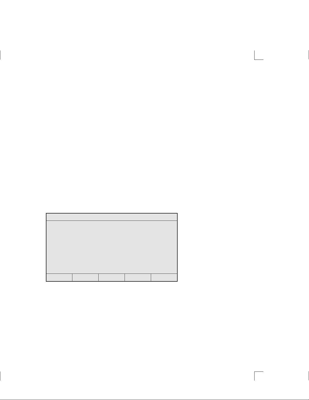
10. Select a syringe fill mode. Valid modes are AUTO or MANUAL.
– Auto mode means that the instrument will perform the fill function
automatically when you run the method.
– Manual mode means you must press the Run/Stop key or press the probe
button to activate the fill function when you run the method.
11. You may, but are not required to, enter an air gap volume.
– If you enter an air gap volume greater than 0, specify a mode type. Valid
mode types are either MANUAL or AUTO.
- If you select MANUAL mode, you must pick up the air gap manually by
using the Run/Stop key or the probe button.
- If you select AUTO mode, the instrument will pick up the air gap
automatically. You may select a time delay period, from 0 to 60 seconds.
The default is 0.3 seconds.
- If you do not select an air gap volume, “N/A” appears in the air gap
mode and delay fields on the screen.
12. The “Probe wash parameters” screen appears:
Probe wash parameters
Wash volume (uL) 0.0
Left Syringe fill speed: 4
Left Syringe dispense speed: 4
SELECT item to edit-ACCEPT if complete
SELECT ESCAPE ACCEPT
Enter fill and dispense speeds. The syringe automatically fills with the wash
volume. However, you must use the Run/Stop key or the probe switch to
complete the wash cycle.
3–22 MICROLAB 510B/511C, 530B/531C, and 540B/541C User’s Manual
Artisan Technology Group - Quality Instrumentation ... Guaranteed | (888) 88-SOURCE | www.artisantg.com
Page 87

– If you are using a ML510B or a ML530B, you can wash the probe directly
from the left syringe.
– If you are using a ML540B, you cannot wash the right syringe or probe.
13. When you are satisfied with your entries, press ACCEPT. The system displays
the “Save method in method memory” screen. Press CONFIRM to save the
method, then press any key to continue.
Creating a Pipette Method
Use this function to create a pipette method. A pipette method aspirates the same
volume as it dispenses. The total actual volume dispensed, however, may include
an air gap volume. A pipette method performs the following tasks:
• With or without a time delay (of up to 60 seconds), aspirate an air gap volume
and then aspirate an amount of sample fluid into the left syringe (if using a
single syringe instrument) or into the right syringe (if using a dual syringe
instrument).
• Dispense both the sample fluid and the air gap volumes from the syringe.
• Wash the syringe.
1. Follow steps 1–8 under “Creating a New Method.” Select the “Pipette method”
function from the “Method type to create” menu. The “Pipette parameters”
screen appears:
Pipette parameters
Right Air gap volume 0.0
Right Dispense volume 250.0
Right Syringe aspirate speed: 2
Right Syringe dispense speed: 2
Air gap mode: N/A
Air gap delay: N/A
SELECT item to edit-ACCEPT if complete
SELECT ESCAPE ACCEPT
Chapter 3 Using the MICROLAB 500 System 3–23
Artisan Technology Group - Quality Instrumentation ... Guaranteed | (888) 88-SOURCE | www.artisantg.com
Page 88

2. You may, but are not required to, enter a Right Air gap volume.
– If you enter an air gap volume greater than 0, specify a mode type. Valid
mode types are either MANUAL or AUTO.
- If you select MANUAL mode, you must pick up the air gap manually by
using the Run/Stop key or the probe button.
- If you select AUTO mode, the instrument will pick up the air gap
automatically. You may select a time delay period, from 0 to 60 seconds.
The default is 0.3 seconds.
- If you do not select an air gap volume, “N/A” appears in the air gap
mode and delay fields on the screen.
3. Enter the Right Dispense volume.
4. Enter a Right Syringe aspirate speed.
5. Enter Right Syringe dispense speed.
6. The “Probe wash parameters” screen appears:
Probe wash parameters
Wash volume (uL) 0.0
Left Syringe fill speed: 4
Left Syringe dispense speed: 4
SELECT item to edit-ACCEPT if complete
SELECT ESCAPE ACCEPT
7. Enter fill and dispense speeds. The syringe automatically fills with the wash
volume. However, you must use the Run/Stop key or the probe switch to
complete the wash cycle.
– If you are using a ML510B or a ML530B, you can wash the probe directly
from the left syringe.
– If you are using a ML540B, you cannot wash the right syringe or probe.
3–24 MICROLAB 510B/511C, 530B/531C, and 540B/541C User’s Manual
Artisan Technology Group - Quality Instrumentation ... Guaranteed | (888) 88-SOURCE | www.artisantg.com
Page 89

8. When you are satisfied with your entries, press ACCEPT. The system displays
the “Save method in method memory” screen. Press CONFIRM to save the
method, then press any key to continue.
Creating a Titrate Method
Use this function to create a titrate method. A titrate method performs the
following functions:
• Fill the left and/or right syringes.
• Dispense an initial volume(s) from the syringe(s).
• Dispense step volume(s) from the syringe(s).
✱ Note: A titrate method is an interactive method that requires
user input each time it is run. For example, you determine whether
or not to perform the next step of the method, based on your
observations of the previous dispensation. Since all titration
methods are interactive, you cannot copy a titration method to a
custom method or download a titration method to the drive unit. ✱
1. Follow steps 1–8 under “Creating a New Method.” Select the “Titrate method”
function from the “Method type to create” menu. The “Titrate” screen appears:
Titrate
Left Right
Fill volume (uL): 2500.0 250.0
Initial volume (uL): 0 .0 0.0
Step volume (uL): 2.5 0.25
SELECT item to edit-ACCEPT if complete
SELECT ESCAPE ACCEPT
Chapter 3 Using the MICROLAB 500 System 3–25
Artisan Technology Group - Quality Instrumentation ... Guaranteed | (888) 88-SOURCE | www.artisantg.com
Page 90

2. Enter a fill volume. The default volume is that of the installed syringe.
– The fill volume must at least equal the initial volume plus one step.
– The fill volume for at least one syringe must be greater than zero (0).
3. Enter an initial volume. The initial volume may be zero, less than the step
volume, or greater than the step volume. Generally, however, initial volume is
greater than the step volume.
4. Enter a step volume. This volume must be larger than zero (0) for at least one
syringe.
5. The “Titrate method parameters” screen appears:
Titrate method parameters
Left Right
Syringe fill speed: 4 2
Initial dispense speed: 4 2
Step dispense speed: 8 8
Step auto-repeat delay: 0.3
SELECT item to edit-ACCEPT if complete
SELECT ESCAPE ACCEPT
6. Enter syringe fill speed(s).
7. Enter initial dispense speed(s).
8. Enter step dispense speed(s).
9. Enter a step auto-repeat delay; this is the time delay between two
dispensations when you press the probe button or the Run/Stop key. Valid
values are from 0–60 seconds.
10. When you are satisfied with your entries, press ACCEPT. The “Save method in
method memory” screen. Press CONFIRM to save the method, then press any
key to continue.
3–26 MICROLAB 510B/511C, 530B/531C, and 540B/541C User’s Manual
Artisan Technology Group - Quality Instrumentation ... Guaranteed | (888) 88-SOURCE | www.artisantg.com
Page 91

Creating a Custom Method
Use this function to create a custom method of your own design.
• You may enter up to 50 command lines; any command line may be executed either
manually or automatically. If you execute commands automatically, you may
delay the execution of each line by 0–60 seconds, in increments of 0.1 seconds.
• Valid syringe operation modes are listed in the following table:
Fill
Fills or picks up liquid from the valve input port (typically,
this is from the reservoir via the diluent syringe).
Return
Aspirate
Dispense
✱ Note: On MICROLAB 530 instruments (D-type syringes, right side
only), Fill and Aspirate perform the same function. Also, Return and
Dispense perform the same function. ✱
Dispenses or returns liquid to the valve input port.
Aspirates or picks up liquid from the output port.
Dispenses liquid to the valve output port.
• You can create a custom method to run a valve without moving the attached
syringe if you set the appropriate volume to zero or if you do not enter a volume
for the syringe.
1. Follow steps 1–8 under “Creating a New Method.” Select the “Custom method”
function from the “Method type to create” menu. The “Custom method” screen
appears. Use the arrow keys to move from field to field. You may enter values
in any order.
Chapter 3 Using the MICROLAB 500 System 3–27
Artisan Technology Group - Quality Instrumentation ... Guaranteed | (888) 88-SOURCE | www.artisantg.com
Page 92

Custom method
Auto Dly Vol---LEFT-Spd Vol--RIGHT-Spd
1:
2:
3:
4:
5:
6:
SELECT item to edit-ACCEPT if complete
SELECT ESCAPE ACCEPT DELETE
2. Auto field: Valid modes are Y or N, indicating that AUTO delay is either on
or off. If the Auto field is blank, AUTO delay is off.
3. DLY (Delay) field. Enter the number of seconds of delay between method steps.
If the Delay field is left blank, there is no delay between method steps.
4. Vol---LEFT field:
– Use the arrow keys to set the mode of the left syringe. Valid modes are:
Fil (Fill), Asp (Aspirate), Dis (Dispense), and Ret (Return fluid to the
reservoir).
– Enter a volume for the left syringe. If the Volume field is left blank, syringe
volume is assumed to be 0.
5. Spd (Speed) field: Enter a speed for the left syringe from 1 to 250 seconds. Speed
must be entered in whole seconds. If the Speed field is left blank, the default
speed for the syringe is used.
6. Vol--Right field:
– Use the arrow keys to set the operation mode of the right syringe. Valid
modes are: Fil (Fill), Asp (Aspirate), Dis (Dispense), and Ret (Return fluid
to the reservoir).
– Enter a volume for the right syringe. If the Volume field is left blank,
syringe volume is assumed to be 0.
3–28 MICROLAB 510B/511C, 530B/531C, and 540B/541C User’s Manual
Artisan Technology Group - Quality Instrumentation ... Guaranteed | (888) 88-SOURCE | www.artisantg.com
Page 93

7. Spd (Speed) field: Enter a speed for the right syringe from 1–250 seconds. The
speed must be entered in whole seconds. If the Speed field is left blank, the
default speed for the syringe is used.
8. Continue adding entries, creating up to 50 lines of commands.
9. When you are satisfied with your entries, press ACCEPT. The controller
displays the “Save method in method memory” screen. Press CONFIRM to save
the method, then press any key to continue.
Running an Existing Method
Use this function to run an existing method. At least one method must exist in the
method storage area for you to use this function. If no method exists, displays a
“Method Memory Empty” error message.
1. From the Main menu, SELECT the “Run an existing method” function. The
following screen appears:
Run an existing method
NEW1 NEW2 NEW3
<UNUSED> <UNUSED> <UNUSED>
<UNUSED> <UNUSED> <UNUSED>
<UNUSED> <UNUSED> <UNUSED>
<UNUSED> <UNUSED> <UNUSED>
<UNUSED> <UNUSED> <UNUSED>
<UNUSED> <UNUSED> <UNUSED>
SELECT an existing method
SELECT ESCAPE
2. Use the arrow keys to highlight a method name, then press SELECT. (You
cannot SELECT an unused method location.)
Chapter 3 Using the MICROLAB 500 System 3–29
Artisan Technology Group - Quality Instrumentation ... Guaranteed | (888) 88-SOURCE | www.artisantg.com
Page 94

3. A screen verifying whether or not the correct syringes are installed appears:
Method type: Methodname
This method requires the following
syringe size(s) to be installed on the
drive unit.
Left Syringe size (uL): 2500.0
Right Syringe size (uL): 250.0
CONFIRM to continue, ESCAPE to exit
ESCAPE CONFIRM
4. The “Drive unit initialization” screen appears. You must respond to this screen
before running the method.
Drive unit initialization
Any fluid in the syringes on the
drive unit will now be purged. Please
ensure the probe is directed towards a
waste area.
CONFIRM to continue, ESCAPE to exit
ESCAPE CONFIRM
5. The contents of the selected method appears on-screen. Follow the on-screen
instructions to run the method.
3–30 MICROLAB 510B/511C, 530B/531C, and 540B/541C User’s Manual
Artisan Technology Group - Quality Instrumentation ... Guaranteed | (888) 88-SOURCE | www.artisantg.com
Page 95

Editing an Existing Method
Use this function to edit an existing method. At least one method must exist in the
method storage area for you to use this function.
1. From the Main menu, SELECT the “Edit an existing method” function. If at least
one method exists, the following screen appears:
Edit an existing method
NEW1 NEW2 NEW3
<UNUSED> <UNUSED> <UNUSED>
<UNUSED> <UNUSED> <UNUSED>
<UNUSED> <UNUSED> <UNUSED>
<UNUSED> <UNUSED> <UNUSED>
<UNUSED> <UNUSED> <UNUSED>
<UNUSED> <UNUSED> <UNUSED>
SELECT an existing method
SELECT ESCAPE
2. Use the arrow keys to highlight an existing method, then press SELECT. (You
cannot highlight an unused method.)
3. The contents of the selected method appears on-screen. Use the arrow keys to
highlight the field you wish edit, then press SELECT. The highlighting
changes to underlining. Use the arrow keys or the numeric keypad to change the
underlined value. When you are satisfied with your edit, press ENTER to
accept the new value.
4. SELECT another field to edit or press ACCEPT to save all changes made to the
method and return to the “Edit an existing method” screen. SELECT another
method to edit or press ESCAPE to return to the Main menu.
✽ Note: Syringe size or configuration cannot be edited from this
screen.
✽
Chapter 3 Using the MICROLAB 500 System 3–31
Artisan Technology Group - Quality Instrumentation ... Guaranteed | (888) 88-SOURCE | www.artisantg.com
Page 96
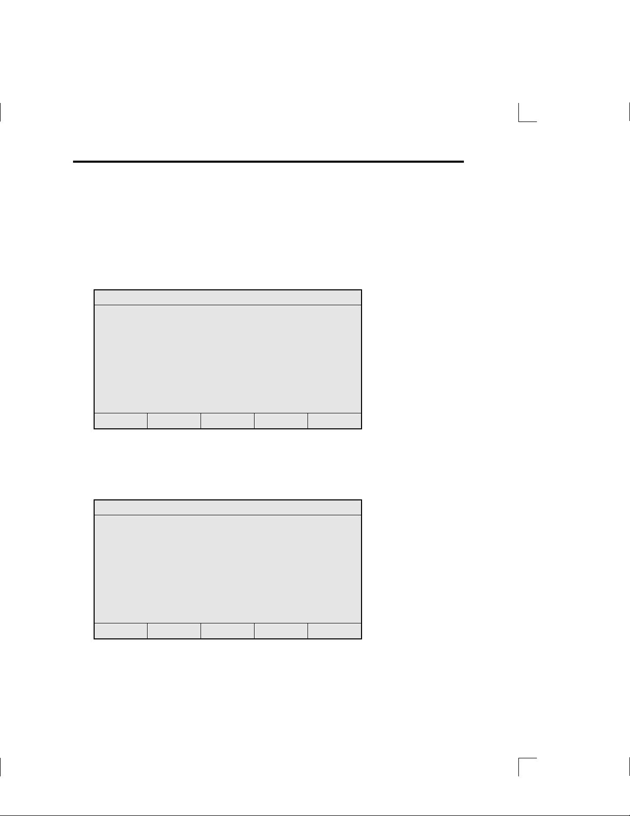
Performing Manual Dilutions
Use the Manual Dilution function to perform manual dilutions without creating and
saving a new dilution method, or without running an existing dilution method.
Manual dilutions cannot be stored in memory.
1. From the Main menu, select the “Manual dilution” function. The “Instrument
configuration” screen appears:
Instrument configuration
One syringe instrument
Two syringe instrument
SELECT menu item
SELECT ESCAPE
2. Use the arrow keys to highlight either a one- or a two-syringe instrument
configuration, then press SELECT.
3. The default value(s) for the selected configuration appear on-screen.
Instrument configuration
One syringe instrument
Two syringe instrument
Left Syringe size (uL): 2500.0
Right Syringe size (uL): 250.0
SELECT item to edit-ACCEPT if complete
SELECT ESCAPE ACCEPT
3–32 MICROLAB 510B/511C, 530B/531C, and 540B/541C User’s Manual
Artisan Technology Group - Quality Instrumentation ... Guaranteed | (888) 88-SOURCE | www.artisantg.com
Page 97

4. Press ACCEPT to retain the default sizes.
5. To change a syringe’s size, use the arrow keys to highlight the appropriate
size, then press SELECT. The highlighting changes to underlining. Use the
arrow keys to increase or decrease syringe size. Press ENTER to accept the new
size. When you are satisfied with the syringe sizes, press ACCEPT.
6. The “Manual dilution” screen appears. The following sample screen shows a
two-syringe instrument:
Manual dilution
Left Right
Syringe speed: 4 2
• Fill volume (uL): 2500.0
Aspirate volume (uL): 0.0 250.0
Dispense volume (uL): 0.0 0.0
SELECT item to edit-RUN to start
SELECT ESCAPE MODE
7. Enter syringe speed(s).
– Enter a fill volume for the left syringe.
– Enter an aspiration volume for the left and right syringes.
– You cannot enter a value for Dispense volume.
Dispense volume = Fill volume + Aspirate volumes.
8. Press CONFIRM.
9. Press the Run/Stop key to start the manual dilution method. The dot in the left
margin moves to indicate the active mode. Press MODE for manual dilution
editing options.
10. Press ESCAPE to exit the method and return to the main menu.
Chapter 3 Using the MICROLAB 500 System 3–33
Artisan Technology Group - Quality Instrumentation ... Guaranteed | (888) 88-SOURCE | www.artisantg.com
Page 98

Performing Manual Dispenses
Use the Manual Dispense function to perform manual dispensations without
creating and saving a new dispense method, or without running an existing dispense
method. Manual dispenses cannot be stored in memory.
1. From the Main menu, select the “Manual dispense” function. The “Instrument
configuration” screen appears:
Instrument configuration
One syringe instrument
Two syringe instrument
SELECT menu item
SELECT ESCAPE
2. Use the arrow keys to highlight either a one- or a two-syringe instrument
configuration, then press SELECT.
3. The default value(s) for the selected configuration appear:
Instrument configuration
One syringe instrument
Two syringe instrument
Left Syringe size (uL): 2500.0
Right Syringe size (uL): 250.0
SELECT item to edit-ACCEPT if complete
SELECT ESCAPE ACCEPT
3–34 MICROLAB 510B/511C, 530B/531C, and 540B/541C User’s Manual
Artisan Technology Group - Quality Instrumentation ... Guaranteed | (888) 88-SOURCE | www.artisantg.com
Page 99

4. Press ACCEPT to retain the default sizes.
5. To change a syringe’s size, use the arrow keys to highlight the size, then press
SELECT. The highlighting changes to underlining. Use the arrow keys to
increase or decrease syringe size. Press ENTER to accept the new size; the
previous screen appears. When you are satisfied with the syringe sizes,
press ACCEPT.
6. The “Manual dispense” screen appears:
Manual dispense
Left Right
Syringe speed: 4 2
• Fill volume (uL): 2500.0 250.00
Dispense volume (uL): 2500.0 250.00
SELECT item to edit-RUN to start
SELECT ESCAPE MODE
7. Enter syringe speed(s).
– Enter a fill volume for the left and right syringes.
– Enter a dispense volume for the left and right syringes.
8. Press CONFIRM.
9. Press the Run/Stop key to start the manual dispense method. The dot in the left
margin moves to indicate the active mode. Press MODE for manual dispense
editing options.
10. Press ESCAPE to exit the method and return to the Main menu.
Chapter 3 Using the MICROLAB 500 System 3–35
Artisan Technology Group - Quality Instrumentation ... Guaranteed | (888) 88-SOURCE | www.artisantg.com
Page 100
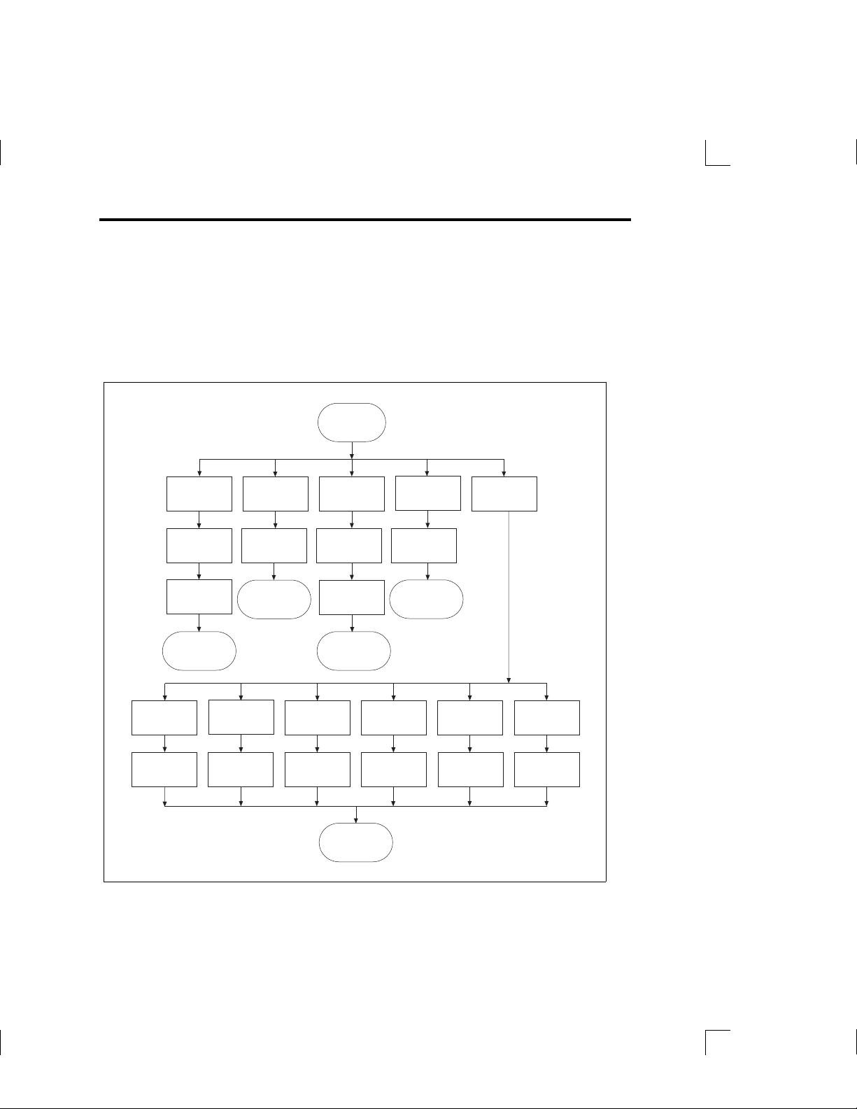
The Utilities Menu
The Utilities menu provides you with tools to manipulate methods and to diagnose
and configure the instrument. Figure 3–5 shows the functions available from the
Utilities menu.
Figure 3–5 The Utilities Menu
Utilities Menu
Confirm and
Utilities menu
Change
default
language
Select
language
Rename
existing
method
Select
method
Rename
method
return to
Confirm and
return to
Utilities menu
Set
baud
rate
Select
rate
Delete
existing
method
Select
method
Copy method
Utilities menu
Turn
caps lock
on/off
Toggle
caps lock
Utilities menu
to custom
method
Select
method
Name
new
method
Save and
return to
Save and
return to
Confirm and
Utilities menu
Perform
display
test
Run
test
Download
method to
base unit
Select
method
return to
configuration
Perform
keyboard
test
Run
test
Diagnostics
and
Set
diagnostic
mode
Select
mode
3–36 MICROLAB 510B/511C, 530B/531C, and 540B/541C User’s Manual
Artisan Technology Group - Quality Instrumentation ... Guaranteed | (888) 88-SOURCE | www.artisantg.com
 Loading...