

Page 1
ESPAÑOL DEUTSCH FRANÇAIS ITALIANO PYCCKO
Spanish German French Italian Russian Japanese Mandarin
Sanus Systems 2221 Hwy 36 West, Saint Paul, MN 55113 USA 11.15.05
Customer Service: (800) 359-5520 • (651) 484-7988 • fax (651) 636-0367
Customer Service Europe: 31 (0)20 5708938 • fax 31 (0)20 5708989
See complementary Sanus products at www.sanus.com
中文
ENGLISH
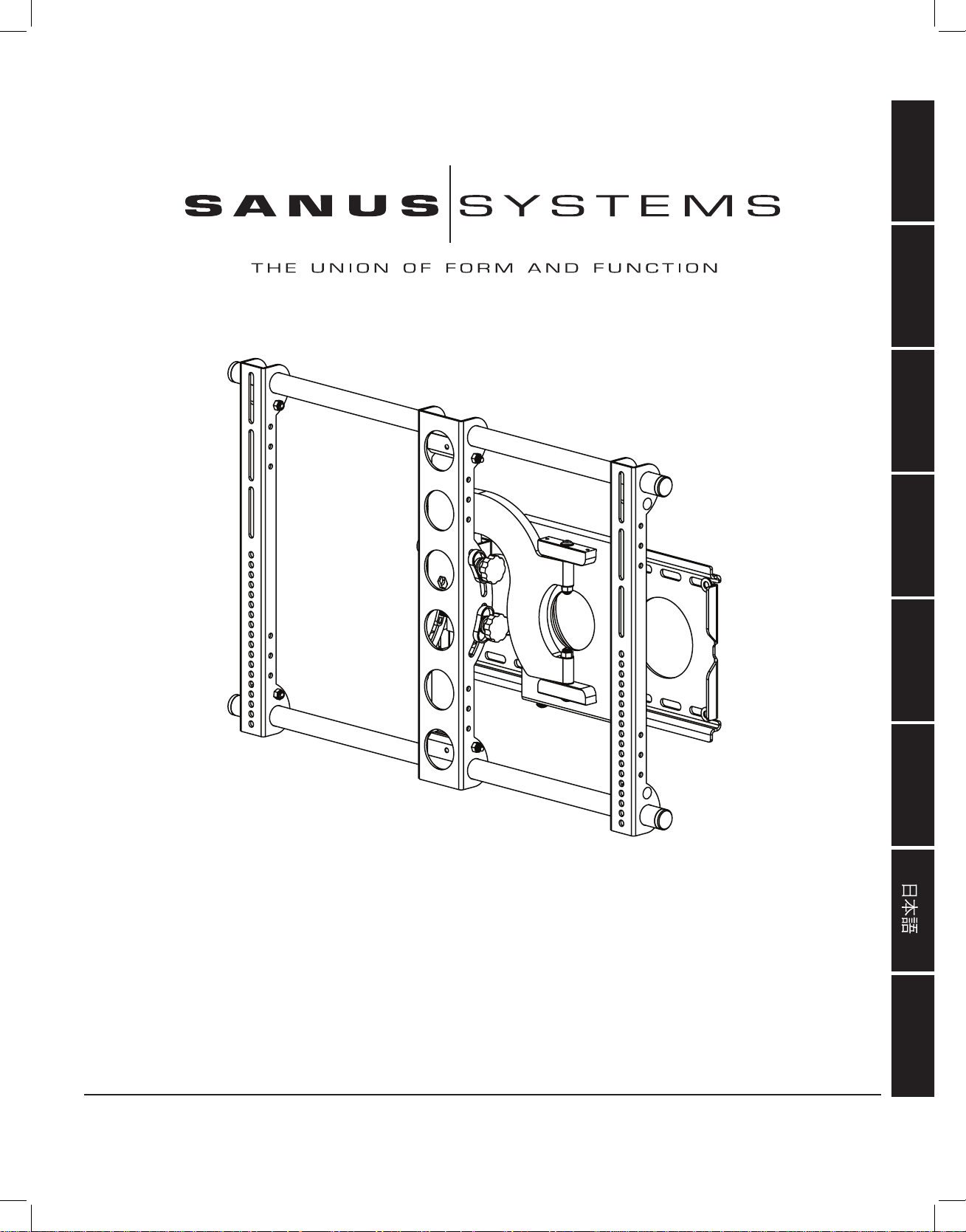
International Assembly Instructions for model VMSA
VMSAins_011206_ML.indd 1 1/16/06 5:21:45 PM
Page 2

VMSAins_011206_ML.indd 2 1/16/06 5:21:46 PM
Page 3
ENGLISH
Assembly Instructions for Model: VMSA
Thank you for choosing a Sanus Systems Vision Mount wall mount. The VMSA is designed to mount up to 50” Flat panel televisions
weighing up to 150 lb. to a vertical wall. It allows you to tilt the television from +5° to -15°. It will also extend 9.5” away from the wall,
swivel up to 30°, and roll ± 6°.
Safety Warning: If you do not understand these directions, or have any doubts about the safety of the installation, please call a qualified contractor or contact Sanus at 800.359.5520 or www.sanus.com. Our customer service representatives can quickly assist you with
installation questions and missing or damaged parts. Replacement parts for products purchased through authorized dealers will be
shipped directly to you. Check carefully to make sure that there are no missing or defective parts. Never use defective parts. Improper
installation may cause damage or serious injury. Do not use this product for any purpose that is not explicitly specified by Sanus Systems. Sanus Systems can not be liable for damage or injury caused by incorrect mounting, incorrect assembly, or incorrect use. Please
call Sanus Systems before returning products to the point of purchase.
Note: The supplied wall mounting hardware is not for metal stud, concrete, brick, or block walls. If you are uncertain about the nature of
your wall, consult an installation contractor. Sanus makes every effort to assure all necessary television mounting hardware is included.
If the hardware you need is not included please consult your local hardware store or call Sanus Systems.
Required Tools: 3/16” drill bit, wrench set, phillips screw driver
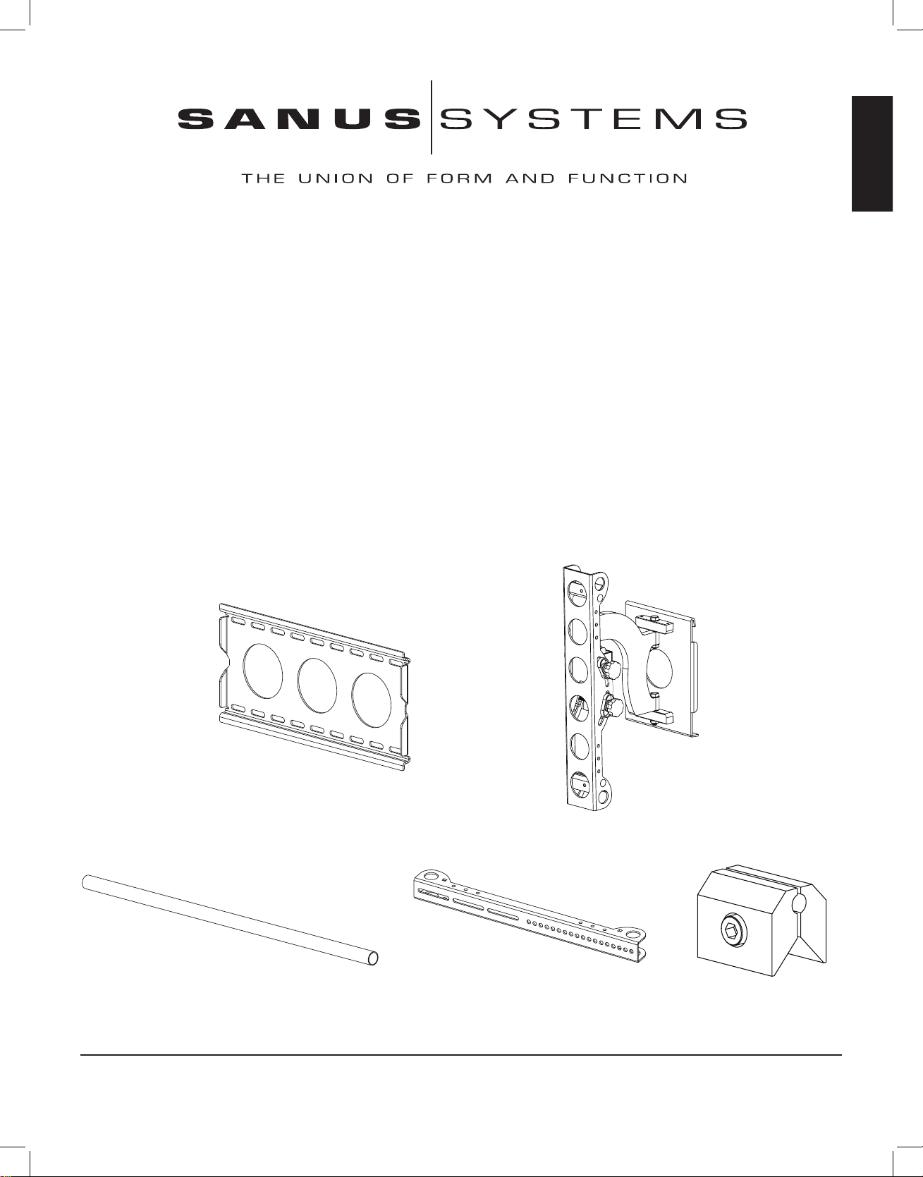
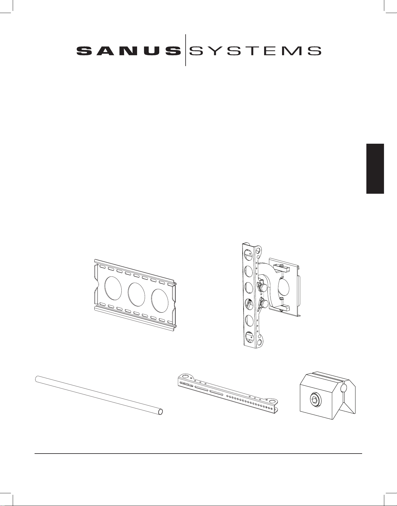
Supplied Parts: Some parts not shown at same scale
*
(1) Wall Plate - a (1) Arm Assembly - b
(2) 1” Diameter Tube - c (2) Monitor Bracket - d (4) Vise Assembly - e
*
Sanus Systems 2221 Hwy 36 West, St. Paul, MN 55113 11.15.05
Customer Service: 800.359.5520. See complementary Sanus products at www.sanus.com
VMSAins_011206_ML.indd 3 1/16/06 5:21:47 PM
Page 4
ENGLISH
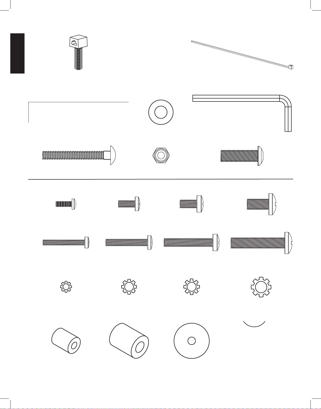
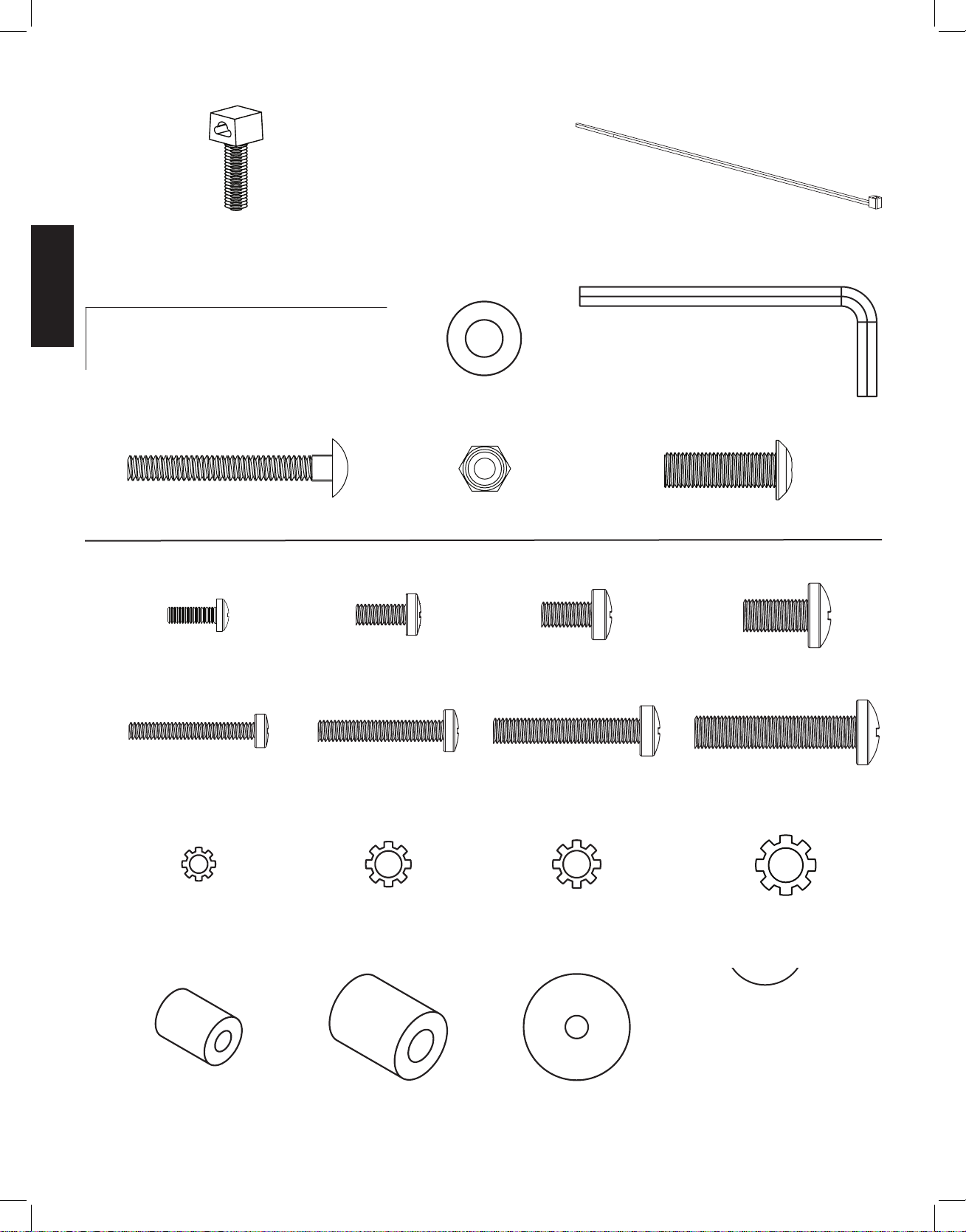
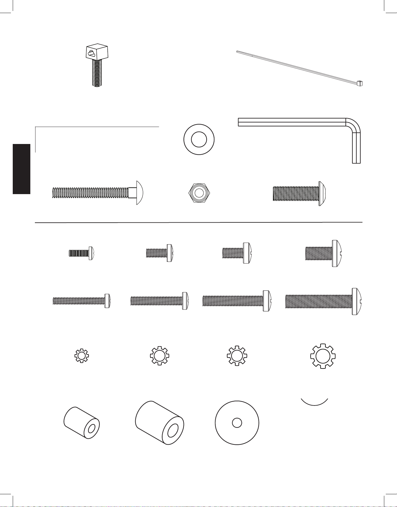
Hardware: Hardware shown is actual size
(2) Wire Tie Clip - f (5) Wire Tie -g
*
(4) Lag Bolt - h (4) Lag Bolt Washer - i (1) Allen Key - j
(4) 2” Carriage Bolt - k (4) 1/4-20 Nut - l (2) Safety Bolt - m
Supplied Television Mounting Hardware: Hardware shown is actual size
(4) M4 x 12mm Bolt - n (4) M5 x 12mm Bolt - o (4) M6 x 12mm Bolt - p (4) M8 x 16mm Bolt - q
(4) M4 x 30mm Bolt - r (4) M5 x 30mm Bolt - s (4) M6 x 35mm Bolt - t (4) M8 x 40mm Bolt - u
(4) M4 Lock Washer - v (4) M5 Lock Washer - w (4) M6 Lock Washer - x (4) M8 Lock Washer - y
(4) M4/M5 Spacer - z (4) M6/M8 Spacer - aa (8) M4/M5 Washer - bb (4) M6/M8 Washer - cc
VMSAins_011206_ML.indd 4 1/16/06 5:21:55 PM
Page 5
ENGLISH
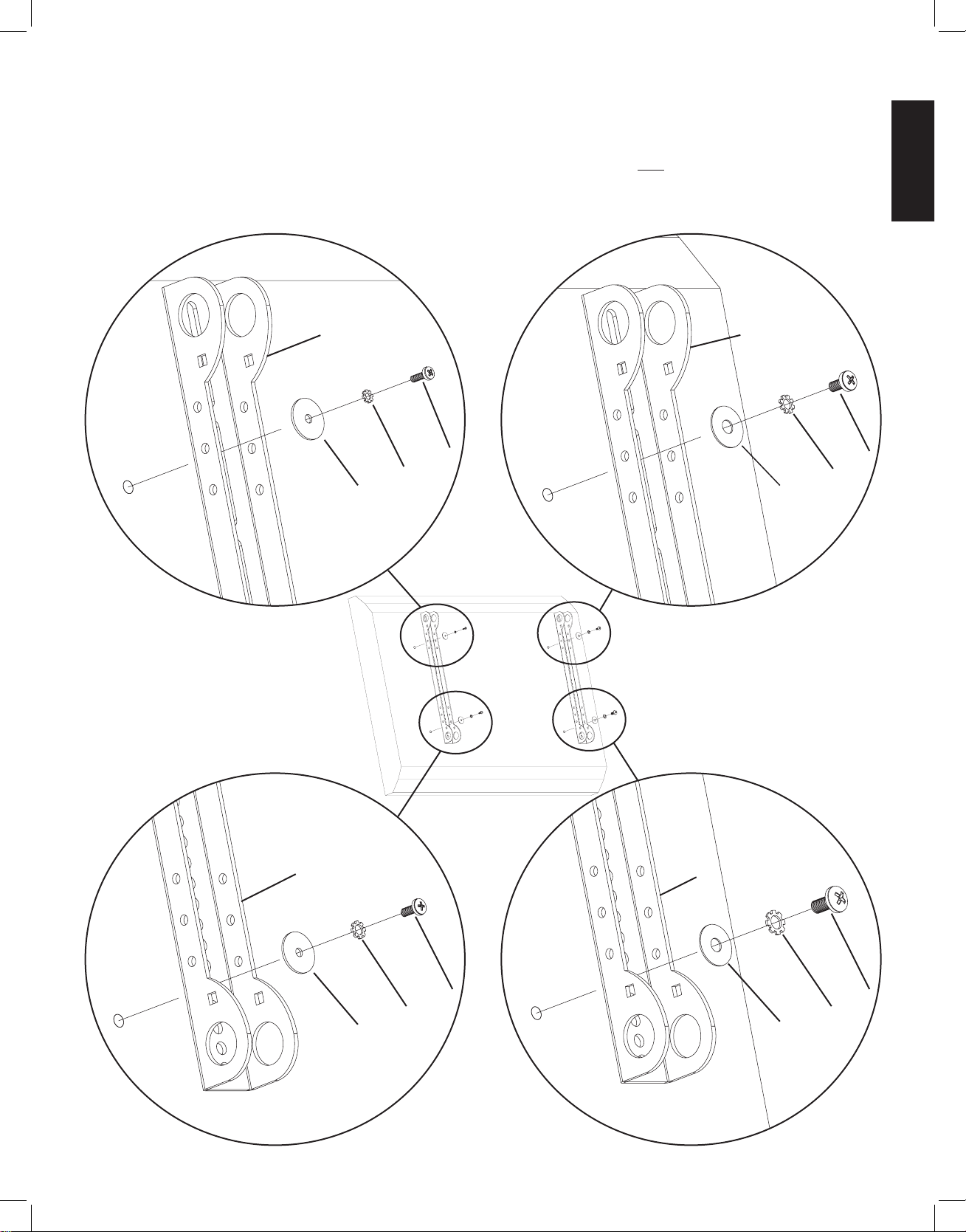
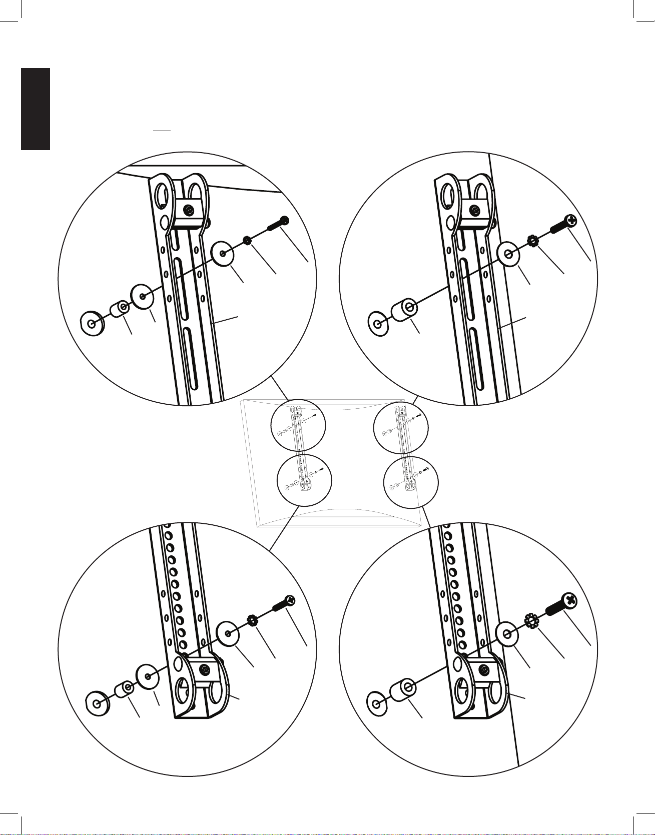
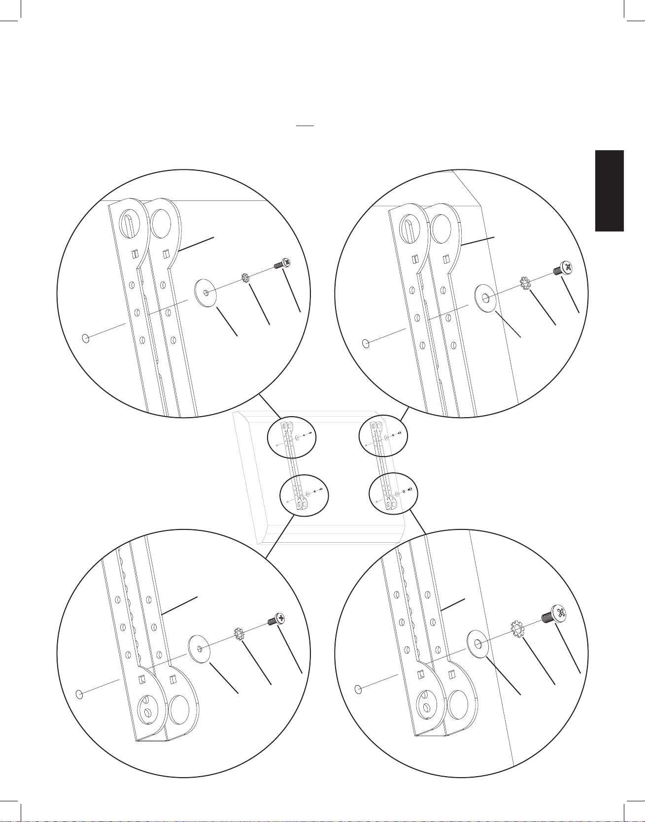
Step 1: Mounting Monitor Brackets to a television with a Flat Back
First, determine the diameter of the Bolt (n,o,p,q) your TV requires by hand threading them into the threaded insert on the back of the TV.
If you encounter any resistance stop immediately! Once you have determined the correct diameter, see the appropriate Diagram below. You
will thread the Bolt through the appropriate Lock Washer (v,w,x,y), a Washer (bb,cc), the Monitor Bracket (d) and finally into the TV. Make
sure the Monitor Brackets are vertically centered and level with each other. Repeat process until each Monitor Bracket is secured to the TV
with 2 bolts.
Note: For TVs with a curved back or any other obstruction See Step 2. After completing this step, proceed to Step 3.
M4 Diameter Bolt M6 Diameter Bolt
d d
n p
v x
bb cc
Diagram 1
M5 Diameter Bolt M8 Diameter Bolt
d d
o q
w y
bb cc
VMSAins_011206_ML.indd 5 1/16/06 5:21:55 PM
Page 6
ENGLISH
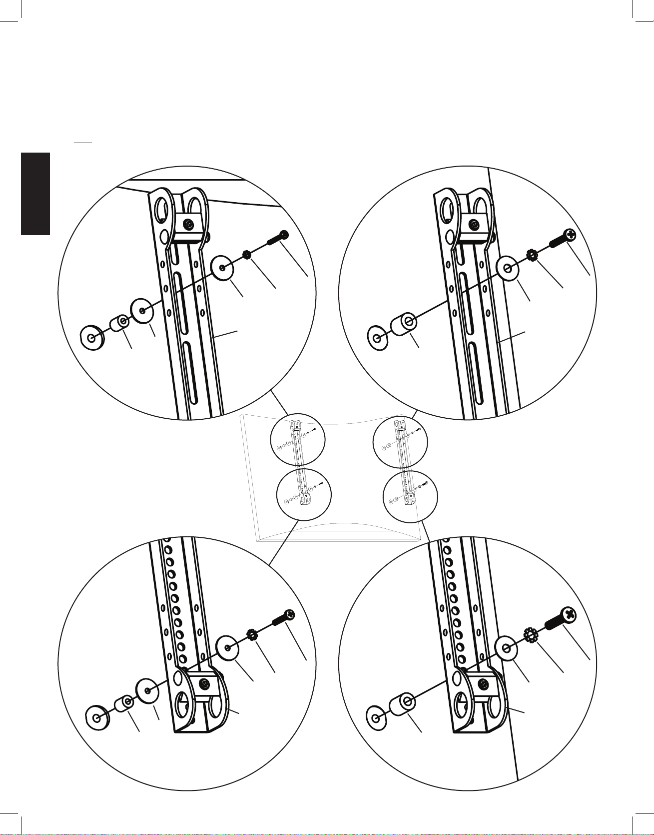
Step 2: Mounting the Monitor Brackets to a television with a curved back or any other obstruction.
First, determine the diameter of the Bolt (r,s,t,u) your TV requires by hand threading them into the threaded insert on the back of the TV. If
you encounter any resistance stop immediately! Once you have determined the correct diameter, see the appropriate Diagram below. You
will thread the Bolt through the appropriate Lock Washer (v,w,x,y), a Washer (bb,cc), the Monitor Bracket (d), a second Washer (bb - M4/M5
diameter only), a Spacer (z,aa), and finally into the TV. Make sure the Monitor Brackets are vertically centered and level with each other.
Repeat the process until each Monitor Bracket is secured to the TV with 2 bolts.
M4 Diameter Bolt M6 Diameter Bolt
r t
v x
bb cc
d d
bb
z aa
Diagram 2
M5 Diameter Bolt M8 Diameter Bolt
s u
w y
bb cc
d d
bb
z aa
VMSAins_011206_ML.indd 6 1/16/06 5:21:57 PM
Page 7
ENGLISH
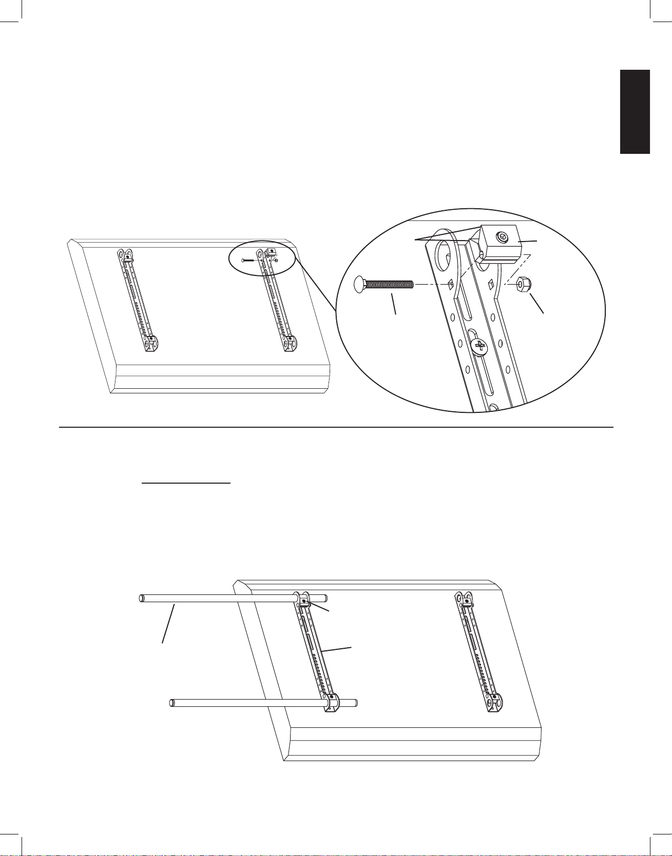
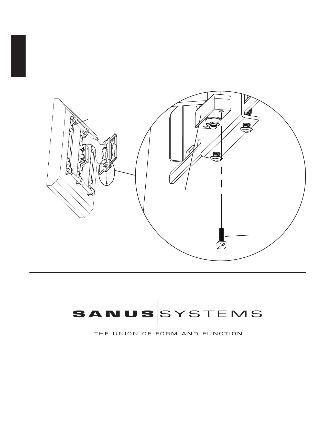
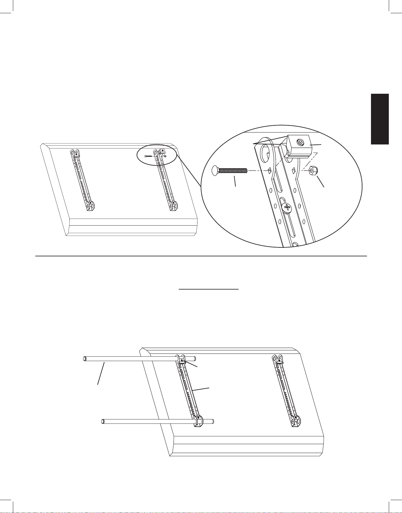
Step 3: Add the Vise Assemblies to the Monitor Brackets:
Note: Do not overtighten the 1/4-20 Nut (l). The Vise Assembly (e) should be able to rotate freely around the Carriage Bolt (k).
Place the Vise Assembly (e) between the two sides of the Monitor Bracket (d) so that the two jaws point toward the set of 1” diameter
holes and the allen bolt is facing away from the television. Place a 2” Carriage Bolt (k) through the square hole in the side of the Monitor
Bracket, through the hole in the Vise Assembly, and then through the square hole in the other side of the Monitor Bracket. Next, tighten
a 1/4-20 Nut (l) onto the end of the 2” Carriage bolt. Repeat this step for the bottom of the Monitor Bracket. Finally, repeat these two
steps for the second Monitor Bracket. See Diagram 3 for assistance.
Detailed View
Diagram 3
jaws e
k l
Step 4: Attach the Arm Assembly to the Television (Part I)
Warning: The 1” Diameter Tubes (c) must extend beyond the outside edges of both Monitor Brackets (d) and the
Allen Bolts in all 6 Vise Assemblies (e) must be tightened for the installation to be safe!
First, orient each Vise Assembly (e) so that a 1” Diameter Tube (c) will pass through the 1” round hole in the Monitor Bracket (d) and
then between the jaws of the Vise Assembly. Insert a 1” Diameter Tube through the top hole in the first Monitor Bracket. Repeat this step
for the Bottom hole in the same Monitor Bracket. See Diagram 4a for assistance.
Diagram 4a
e
c d
VMSAins_011206_ML.indd 7 1/16/06 5:21:58 PM
Page 8
ENGLISH
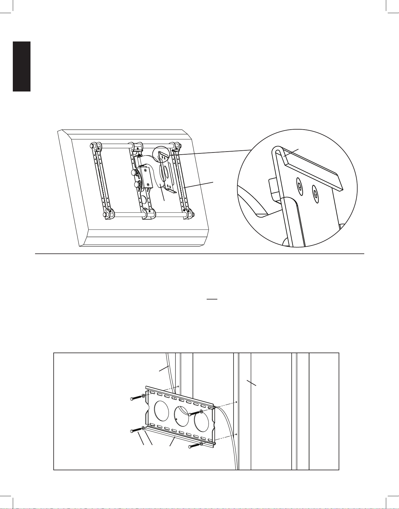
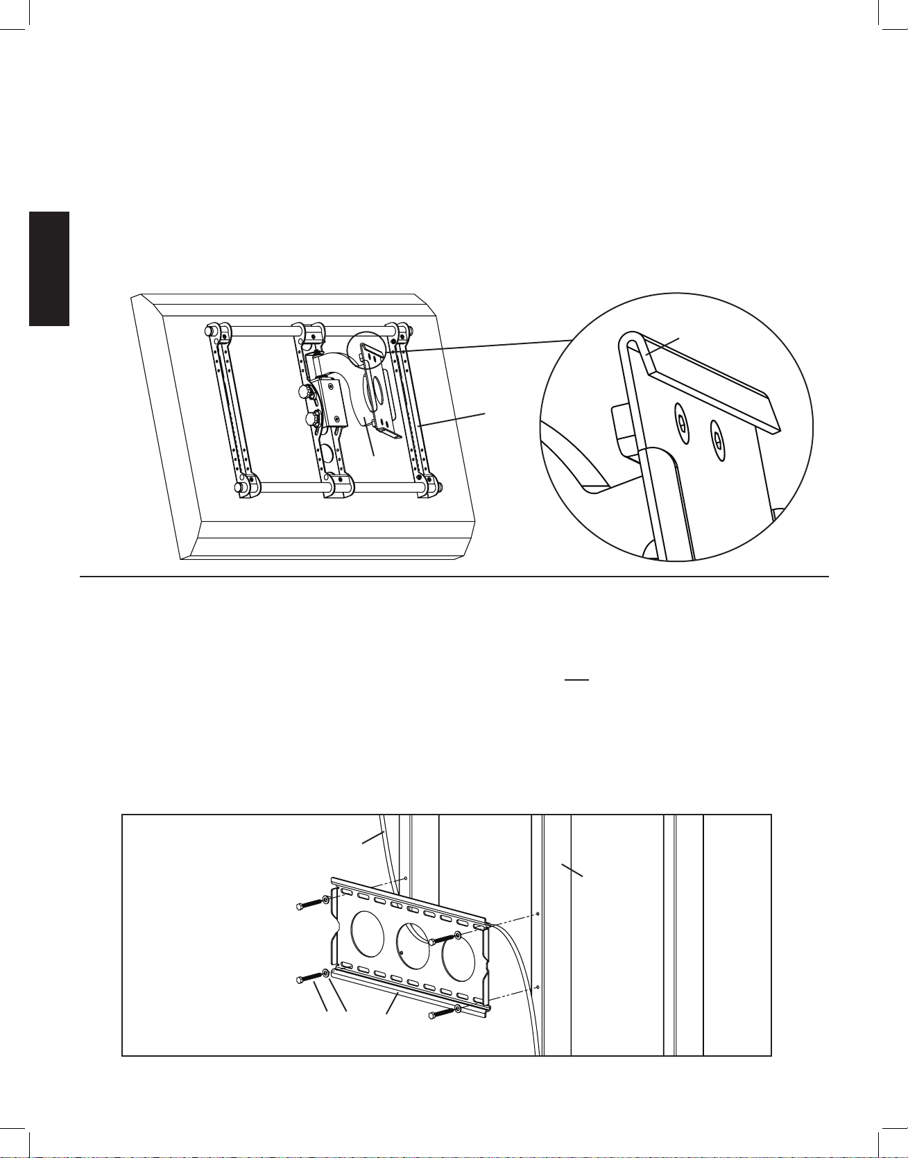
Step 4: Attach the Arm Assembly to the Television (Part II)
Position the Arm Assembly (b) so that the hook shaped tab shown in the Detailed View of Diagram 4b is on the top. Line up the two 1”
diameter holes in the Monitor Bracket (d) at the other end of the Arm Assembly with the with the 1” Diameter Tubes (c). Continue to
push the 1” Diameter Tubes through the vise assembly on the Arm Assembly and then through the other Monitor Bracket. Again, make
sure the Vise Assemblies on both the Arm Assembly and the second Monitor Bracket are oriented so that the 1” Diameter Tubes will
pass between the jaws. Once the 1” Diameter Tubes are in place, tighten the allen bolts on the 4 Vise Assemblies in the two Monitor
Brackets with the Allen Key (j) to lock the television to the mount. Next, slide the Arm Assembly into the desired position between the
two Monitor Brackets and tighten the two remaining Vise Assemblies inside the Arm Assembly.
Note: Sanus recommends Arm Assembly to be centered between Monitor Brackets
Diagram 4b Detailed View
tab
d
b
Step 5: Attach the Wall Plate: Wood Stud mounting options only.
Warning: DO NOT OVERTIGHTEN THE LAG BOLTS! Tighten Lag Bolts (h) only until the Lag Bolt Washer (i) is pulled
rmly against the Wall Plate (a).
Wood Stud Mounting: The Wall Plate (a) must be mounted to two wood studs at least 12” apart. Use a high quality stud
sensor to locate two adjacent studs. It is a good idea to verify where the studs are located with an awl or thin nail. Pre-drill a 2.5” deep
hole in each stud at the desired height using a 3/16” drill bit. Make sure these holes are in the center area of the studs and level with each
other. Use the Wall Plate as a template to mark the location of the second hole in each stud. Drill 2.5” deep holes using the 3/16” drill
bit in the marked location. Attach the Wall Plate to the wall using four Lag Bolts (h) and four Lag Bolt Washers (i). Make sure the Wall
Plate is oriented so the flat surface in the center of the plate is against the wall as shown in Diagram 5.
Diagram 5
drywall cut away to show stud location
stud
h i a
VMSAins_011206_ML.indd 8 1/16/06 5:22:00 PM
Page 9
ENGLISH
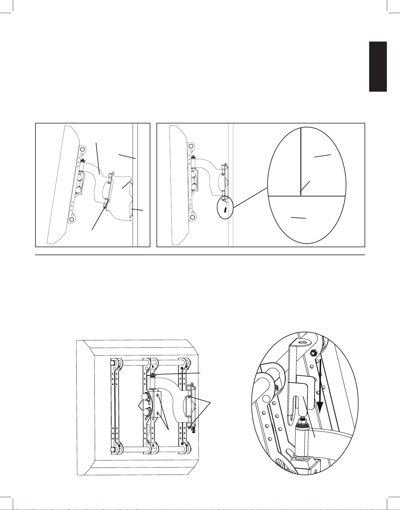
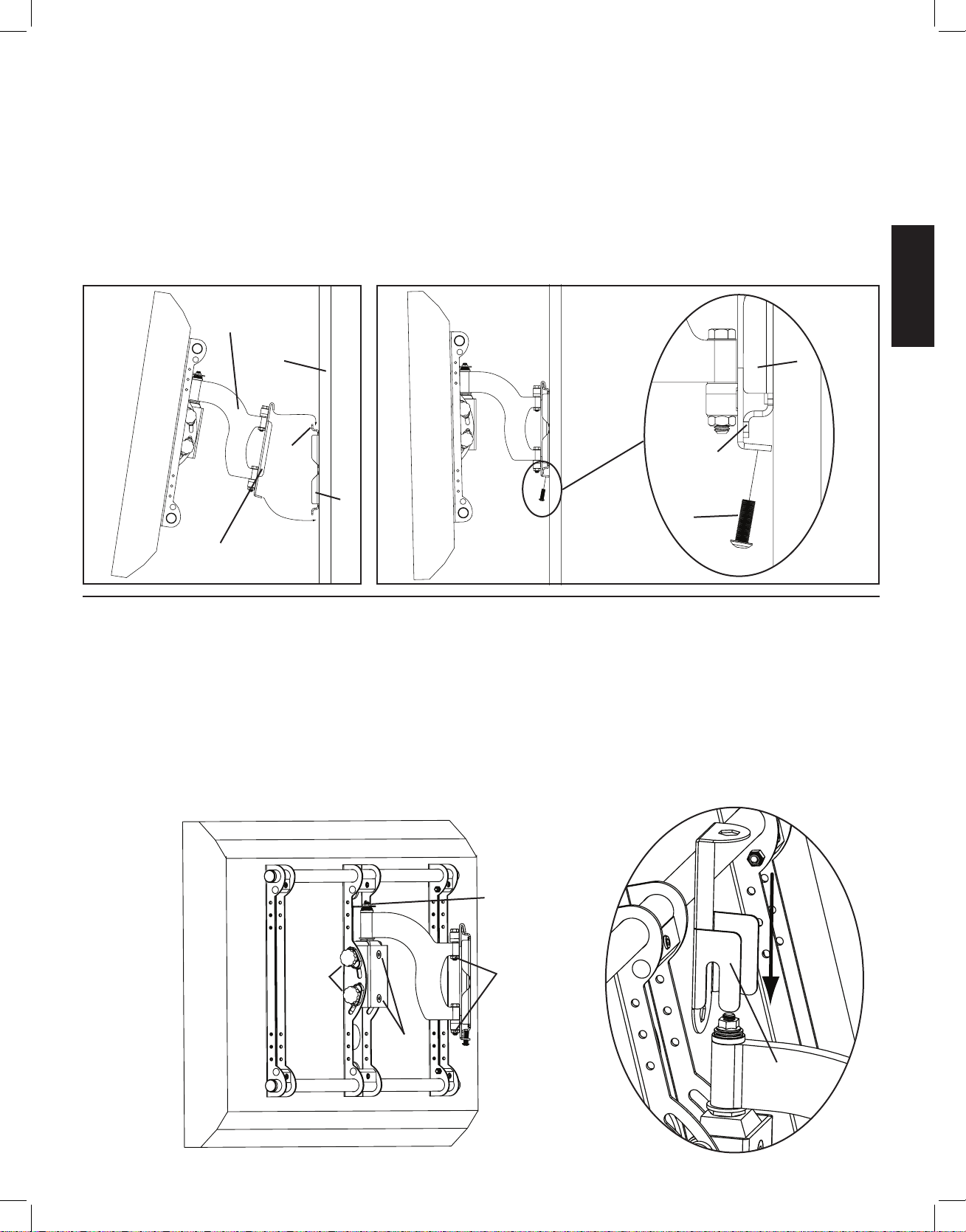
Step 6: Hang the assembly onto the Wall Plate
Warning: This step may require 2 people to lift the assembly onto the Wall Plate! Sanus is not responsible for injury
or damage.
Orient the Arm Assembly (b) so that the arm extends directly away from the television and the transfer plate is parallel with the television. Some televisions may require 2 people to lift. Lift up the assembly and hook the transfer plate onto the tab on the top of the
Wall Plate (a) as shown in Diagram 6a. Adjust the transfer plate side to side on the Wall Plate until it is in the desired location. Thread
each Safety Bolt (m) into one of the two holes in the bottom of the transfer plate and tighten them with the Allen Key (j) so that they are
behind the tab on the bottom of the Wall plate as shown in Diagram 6b.
Diagram 6a Diagram 6b
b
wall a
tab tab
a
m
transfer plate
Step 7: Leveling the Monitor and Adjusting the Tension
WARNING: Do NOT REMOVE the tension nuts labeled in Diagram 7!
Once the television is mounted onto the Wall Plate (a), and the Safety Bolts (m) are tight, it can be adjusted to level. Slightly loosen the
two allen bolts on the back of the Arm Assembly (b). Once those two bolts are loosened, the television can be adjusted ±6º until level.
When the television is level retighten the two allen bolts. The tilt can be adjusted by simply tilting the TV. To adjust the tension of tilt,
use the tension knobs. The tension nuts labeled in Diagram 7 can be slightly loosened or tightened to adjust the tension of the Arm Assembly. If you need to adjust the tension nut closest to the TV, you must remove the safety bracket, adjust the tension and re-install the
safety bracket as shown in the safety bracket installation view of Diagram 7.
Safety Bracket Installation
Diagram 7
tension nut
tension tension
knobs nut
allen
bolts safety bracket
VMSAins_011206_ML.indd 9 1/16/06 5:22:02 PM
Page 10
ENGLISH
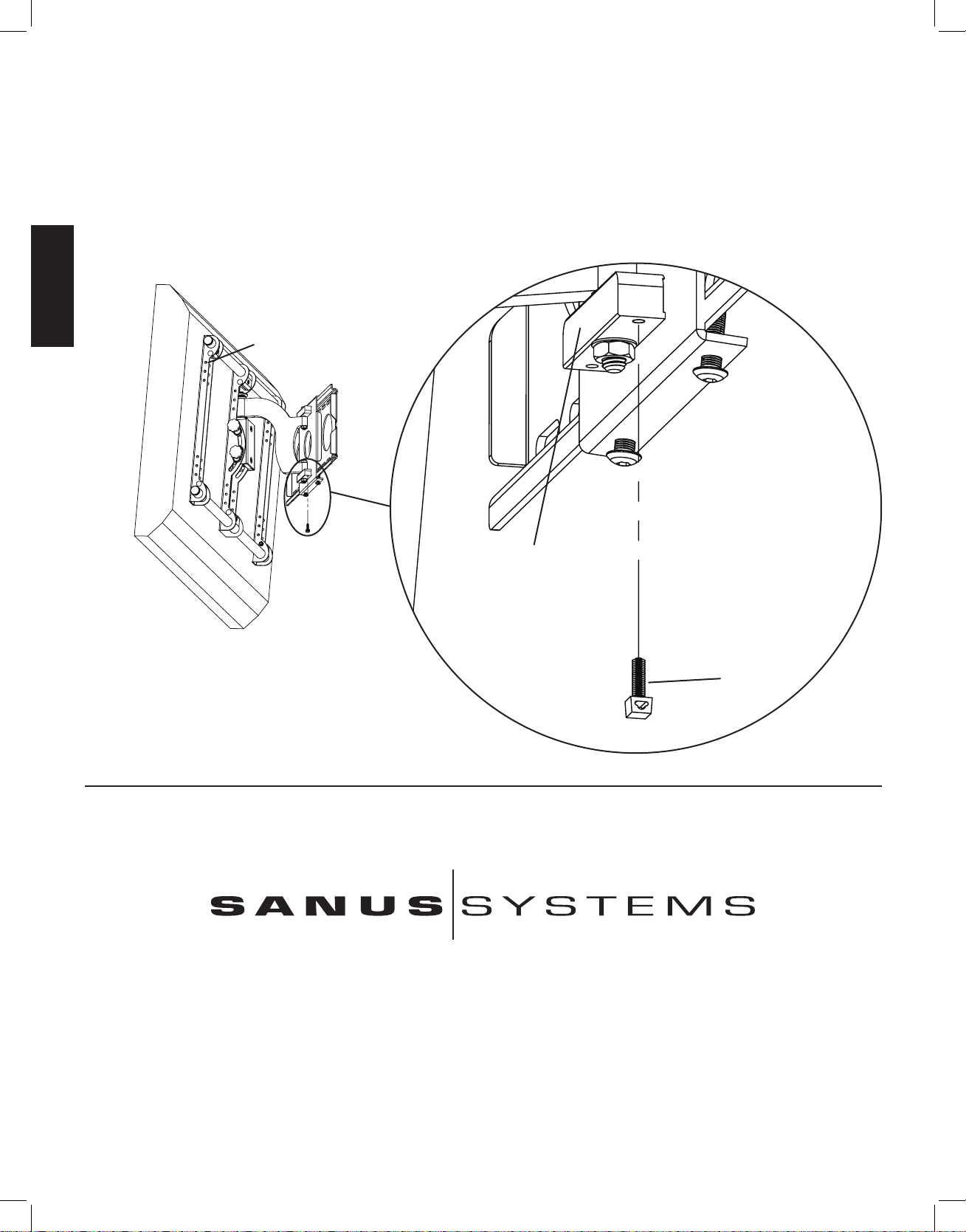
Step 8: Wire Management
Before beginning wire management pull the television into the position as far from the wall as possible. Leave some slack in the cables
so that during motion there is no added tension on the connectors. There are several places to attach wire management ties to keep cords
out of the way. Wire Tie Clips (f) can be attached to the bottom of the pillow block by press fitting them into the pillow block. Wire Ties
(g) can then be added to the Wire Tie Clips, and the holes in the sides of any of the Monitor Brackets (d).
Detailed View
Diagram 8
holes in monitor bracket
pillow block
f
Sanus Systems 2221 Hwy 36 West, St. Paul, MN 55113 11.15.05
Customer Service: 800.359.5520. See complementary Sanus products at www.sanus.com
VMSAins_011206_ML.indd 10 1/16/06 5:22:03 PM
Page 11

ESPAÑOL
L A U N IÓ N D E F O R M A Y F U N C I Ó N
Instrucciones de ensamblaje del modelo: VMSA
Gracias por elegir el soporte para instalación mural Vision Mount de Sanus Systems. El modelo VMSA ha sido diseñado para montar
en una pared vertical televisores con pantalla plana de hasta 50 pulgadas y con un peso de hasta 68 kg. Este modelo permite inclinar el
televisor de +5° a -15°. También puede extenderse 24,1 cm desde la pared, girar hasta 30° e inclinarse horizontalmente ± 6°.
Advertencia de seguridad: Si no entiende estas instrucciones o si tiene alguna duda con respecto a la seguridad de la instalación,
llame a un contratista calificado o llámenos al 800.359.5520 (en EE.UU.) o al 31 (0) 20 5708938 (en Europa). También nos puede visitar
en nuestro sitio www.sanus.com. Nuestros representantes del servicio de atención al cliente le ayudarán oportunamente con cualquier duda
que tenga sobre la instalación o con respecto a piezas faltantes o dañadas. Las piezas de repuesto para los productos comprados a través de
un distribuidor autorizado se enviarán directamente a usted. Revise los productos cuidadosamente para asegurarse de que no falte ninguna
pieza ni esté defectuosa. Nunca use piezas defectuosas. La instalación incorrecta puede provocar daños o lesiones graves. No utilice este
producto para otro fin que no sea el explícitamente especificado por Sanus Systems. Sanus Systems no será responsable por daños ni
lesiones debidos al montaje, ensamblaje o uso incorrectos. Llame a Sanus Systems antes de devolver los productos al punto de compra.
Nota: La tornillería para instalación mural suministrada no es para paredes con vigas de metal ni para paredes de cemento, ladrillo o
con bloques de cemento. Si tiene alguna duda sobre la estructura de la pared, consulte a un contratista sobre la instalación. Sanus hace
todo lo posible para asegurar que se incluya todo el equipo de instalación necesario. Si considera que necesita tornillería que no ha sido
suministrada, consulte en una ferretería local o llame a Sanus Systems.
Herramientas necesarias: Broca de 3/16 pulgadas, juego de llaves inglesas, destornillador Phillips.
Piezas suministradas: Algunas piezas no se muestran a la misma escala
*
(1) Placa para pared - a (1) Brazo - b
(2) Tubo de 2,5 cm de diámetro - c (2) Soporte del monitor - d (4) Placa de sujeción - e
*
Sanus Systems 2221 Hwy 36 West, St. Paul, MN 55113 USA 15-11-05
Servicio de atención al cliente: (800) 359-5520. Vea los productos complementarios de Sanus en el sitio www.sanus.com
VMSAins_011206_ML.indd 11 1/16/06 5:22:04 PM
Page 12
ESPAÑOL
Tornillería: La tornillería se muestra a tamaño real
(2) Mordazas para sujetar el cable - f (5) Amarre del cable -g
*
(4) Tirafondo - h (4) Arandela de tirafondo - i (1) Llave allen - j
(4) Perno de carrocería de 5,1 cm - k (4) Tuerca 1/4-20 - l (2) Perno de seguridad - m
Tornillería suministrada para instalación del televisor: La tornillería se muestra a tamaño real
(4) Perno M4 x 12 mm - n (4) Perno M5 x 12 mm - o (4) Perno M6 x 12 mm - p (4) Perno M8 x 16 mm - q
(4) Perno M4 x 30 mm - r (4) Perno M5 x 30 mm - s (4) Perno M6 x 35 mm - t (4) Perno M8 x 40 mm - u
(4) Arandela de seguridad M4 - v (4) Arandela de seguridad M5 - w (4) Arandela de seguridad M6 - x (4) Arandela de seguridad M8 - y
(4) Espaciador M4/M5 - z (4) Espaciador M6/M8 - aa (8) Arandela M4/M5 - bb (4) Arandela M6/M8 - cc
VMSAins_011206_ML.indd 12 1/16/06 5:22:05 PM
Page 13
ESPAÑOL
Paso 1: Instalación de los soportes del monitor para un televisor con la parte trasera plana
Determine primero el diámetro del perno (n,o,p,q) que necesita el televisor. Para ello deberá enroscar los pernos con la mano en el inserto
roscado que se encuentra en la parte trasera del televisor. ¡Si encuentra alguna resistencia, deténgase inmediatamente! Una vez que haya
determinado el diámetro correcto, vea el diagrama correspondiente más abajo. Enrosque el perno en el televisor a través de la arandela de
seguridad correcta (v,w,x,y), una arandela (bb,cc) y el soporte del monitor (d). Asegúrese de que los soportes del monitor queden centrados
verticalmente y nivelados entre sí. Repita el proceso hasta que cada soporte del monitor quede asegurado con 2 pernos al televisor.
Nota: Para televisores con la parte trasera curva o con cualquier otra obstrucción, vea el paso 2. Después de
completar este paso, proceda al paso 3.
Perno de diámetro M4 Perno de diámetro M6
d d
n p
v x
bb cc
Diagrama 1
Perno de diámetro M5 Perno de diámetro M8
d d
o q
w y
bb cc
VMSAins_011206_ML.indd 13 1/16/06 5:22:05 PM
Page 14
ESPAÑOL
Paso 2: Instalación de los soportes del monitor para un televisor con la parte trasera curva o con cualquier otra obstrucción
Determine primero el diámetro del perno (r,s,t,u) que necesita el televisor. Para ello deberá enroscar los pernos con la mano en el inserto
roscado que se encuentra en la parte trasera del mismo. ¡Si encuentra alguna resistencia, deténgase inmediatamente! Una vez que haya
determinado el diámetro correcto, vea el diagrama correspondiente más abajo. Enrosque el perno en el televisor a través de la arandela de
seguridad correcta (v,w,x,y), una arandela (bb,cc), el soporte del monitor (d), una segunda arandela (bb - de diámetro M4/M5 solamente) y
un espaciador (z,aa). Asegúrese de que los soportes del monitor queden centrados verticalmente y nivelados entre sí. Repita el proceso hasta
que cada soporte del monitor quede asegurado con 2 pernos al televisor.
Perno de diámetro M4 Perno de diámetro M6
r t
v x
bb cc
d d
bb
z aa
Diagrama 2
Perno de diámetro M5 Perno de diámetro M8
s u
w y
bb cc
d d
bb
z aa
VMSAins_011206_ML.indd 14 1/16/06 5:22:06 PM
Page 15
ESPAÑOL
Paso 3: Adición de las placas de sujeción a los soportes del monitor
Nota: No apriete demasiado la tuerca 1/4-20 (l). La placa de sujeción (e) debe poder girar libremente alrededor del
perno de carrocería (k).
Coloque la placa de sujeción (e) entre los dos laterales del soporte del monitor (d) de manera que las dos mordazas queden orientadas
hacia el conjunto de agujeros de 2,5 cm de diámetro y el perno allen quede orientado en sentido opuesto al televisor. Haga pasar un
perno de carrocería de 5,1 cm (k) a través del agujero cuadrado del lateral del soporte del monitor, a través del agujero de la placa de
sujeción y luego por el agujero cuadrado situado en el otro lateral del soporte del monitor. A continuación, apriete una tuerca 1/4-20 (l)
en el extremo del perno de carrocería de 5,1 cm. Repita este paso en la parte inferior del soporte del monitor. Finalmente, repita estos
dos pasos en el otro soporte del monitor. Vea el diagrama 3 como ayuda.
Vista detallada
Diagrama 3
mordazas
e
k l
Paso 4: Conexión del brazo al televisor (primera parte)
Advertencia: ¡Los tubos de 2,5 cm de diámetro (c) se deben extender más allá de los bordes exteriores de los dos
soportes de monitor (d) y los pernos allen en las 6 placas de sujeción (e) se deben apretar para que la instalación
quede bien asegurada!
Oriente primero cada placa de sujeción (e) de manera que un tubo de 2,5 cm de diámetro (c) pueda pasar por el agujero redondo de 2,5 cm
del soporte del monitor (d) y después entre las mordazas de la placa de sujeción. Inserte un tubo de 2,5 cm de diámetro en el agujero superior
del primer soporte del monitor. Repita este paso en el agujero inferior del mismo soporte del monitor. Vea el diagrama 4a como ayuda.
Diagrama 4a
e
c d
VMSAins_011206_ML.indd 15 1/16/06 5:22:06 PM
Page 16
ESPAÑOL
Paso 4: Conexión del brazo al televisor (segunda parte)
Coloque el brazo (b) de manera que la pestaña en forma de gancho que se muestra en la vista detallada del diagrama 4b quede en la parte superior.
Alinee los dos agujeros de 2,5 cm de diámetro que se encuentran en el soporte del monitor (d), en el otro extremo del brazo, con los tubos de 2,5 cm de
diámetro (c). Continúe empujando los tubos de 2,5 cm de diámetro a través de la placa de sujeción situada en el brazo y luego a través del otro soporte
del monitor. Nuevamente, asegúrese de que las placas de sujeción, tanto en el brazo como en el segundo soporte del monitor, queden orientadas de
manera que los tubos pasen entre las mordazas. Una vez que los tubos estén en su lugar, y para fijar el televisor al montaje, utilice una llave allen (j)
para ajustar los pernos allen situados en las 4 placas de sujeción de los dos soportes del monitor. Deslice a continuación el brazo hasta la posición
deseada entre los dos soportes del monitor y apriete las dos placas de sujeción restantes que se encuentran en la parte interior del brazo.
Nota: Sanus recomienda que el brazo quede centrado entre los soportes del monitor.
Diagrama 4b Vista detallada
pestaña
d
b
Paso 5: Conexión de la placa para pared: Opción de instalación en viga de madera solamente
Advertencia: ¡NO APRIETE DEMASIADO LOS TIRAFONDOS! Apriete los tirafondos (h) sólo hasta que la arandela
correspondiente (i) quede rmemente apoyada contra la placa para pared (a).
Instalación sobre viga de madera:La placa para pared (a) se debe montar sobre dos vigas de madera separadas al menos
30,5 cm.
Utilice un detector de vigas de alta calidad para localizar dos vigas adyacentes. Es una buena idea verificar la ubicación de las vigas
con un punzón o clavo delgado. Taladre con antelación en cada viga un agujero de 6,4 cm de profundidad a la altura deseada utilizando una broca
de 3/16 pulgadas. Asegúrese de que estos agujeros estén en la parte central de las vigas y nivelados entre sí. Utilice la placa para pared como una
plantilla para marcar la posición del segundo agujero en cada viga. Taladre agujeros de 6,4 cm con una broca de 3/16 pulgadas en la ubicación
marcada. Instale la placa para pared en la pared utilizando los cuatro tirafondos (h) y las cuatro arandelas de tirafondo (i). Asegúrese de que la
placa para pared esté orientada de manera que la superficie plana del centro de la placa quede contra la pared, como se ilustra en el diagrama 5.
Diagrama 5
Sector de pared de yeso cortada para
mostrar la ubicación de la viga
viga
h i a
VMSAins_011206_ML.indd 16 1/16/06 5:22:07 PM
Page 17
ESPAÑOL
Paso 6: Colgado del conjunto en la placa para pared
Advertencia: ¡En este paso podrían necesitarse 2 personas para levantar el conjunto hasta la placa para pared!
Sanus no será responsable por lesiones o daños.
Oriente el brazo (b) de manera que se extienda directamente desde el televisor y la placa de transferencia quede paralela a este último.
Se requieren dos personas para levantar algunos televisores. Levante el conjunto y enganche la placa de transferencia
en la pestaña que se encuentra en la parte superior de la placa para pared (a), tal como se ilustra en el diagrama 6a. Ajuste la placa de
transferencia de lado a lado en la placa para pared hasta que quede en la posición deseada. Enrosque cada perno de seguridad (m) en uno
de los dos agujeros de la parte inferior de la placa de transferencia y apriételos con la llave allen (j) de manera que queden detrás de la
pestaña que se encuentra en la parte inferior de la placa para pared, como se ilustra en el diagrama 6b.
Diagrama 6a Diagrama 6b
b
pared a
pestaña pestaña
a
m
placa de transferencia
Paso 7: Nivelación del monitor y ajuste de la tensión
ADVERTENCIA: ¡NO RETIRE las tuercas reguladoras de la tensión que se muestran en el diagrama 7!
Una vez que el televisor esté montado en la placa para pared (a) y los pernos de seguridad (m) estén apretados, se podrá ajustar el nivel.
Afloje ligeramente los dos pernos allen de la parte trasera del brazo (b). Una vez que ambos pernos estén aflojados, el televisor podrá
ajustarse ±6 º hasta que quede nivelado. Después de nivelar el televisor, vuelva a apretar los dos pernos allen. La inclinación puede
ajustarse simplemente inclinando el televisor. Para ajustar la tensión de la inclinación, utilice los mandos para regular la tensión. Las
tuercas reguladoras de la tensión que se muestran en el diagrama 7 pueden aflojarse o apretarse ligeramente para ajustar la tensión del
brazo. Si necesita ajustar la tuerca reguladora de la tensión más cercana al televisor, deberá retirar el soporte de seguridad, ajustar la
tensión y finalmente volver a instalar el soporte de seguridad tal como se muestra en la vista correspondiente del diagrama 7.
Instalación del soporte de seguridad
Diagrama 7
tuerca reguladora
de la tensión
mandos
reguladores
de la
tuercas reguladoras
tensión de la tensión
pernos
allen
soporte de
seguridad
VMSAins_011206_ML.indd 17 1/16/06 5:22:07 PM
Page 18
ESPAÑOL
Paso 8: Manejo de los cables
Antes de iniciar la instalación de los cables, mueva el televisor a la posición más alejada de la pared posible. Deje algo de holgura en
los cables, de manera que durante el movimiento no se produzca tensión adicional en los conectores. Hay varios lugares para conectar
los amarres de los cables para mantener los cables asegurados sin que obstruyan el paso. Las mordazas para sujetar el cable (f) pueden
colocarse en la parte inferior del bloque de soporte presionándolas para que encajen en éste. Podrán luego agregarse los amarres del
cable (g) a las mordazas para sujetar el cable y a los agujeros laterales de cualquiera de los soportes del monitor (d).
Vista detallada
Diagrama 8
agujeros en el soporte
del monitor
bloque de soporte
f
Sanus Systems 2221 Hwy 36 West. St. Paul, MN 55113 USA 15-11-05
Servicio de atención al cliente: (800) 359-5520. Vea los productos complementarios de Sanus en el sitio www.sanus.com
VMSAins_011206_ML.indd 18 1/16/06 5:22:08 PM
Page 19
DEUTSCH
D I E E IN H E I T V O N F O R M U N D F U N K T I O N
Sanus Systems 2221 Hwy 36 West. St. Paul, MN 55113 USA 15.11.05
Kundendienst: 800.359.5520. Siehe ergänzende Sanus-Produkte unter www.sanus.com.
Montageanweisungen für Modell VMSA
Wir freuen uns, dass Sie sich für eine Vision Mount-Wandhalterung von Sanus Systems entschieden haben. Das Modell VMSA ist für
die Montage von LCD-Flachbildfernsehern mit einer Bildschirmdiagonale von 50 Zoll und einem Gewicht von maximal 68 kg an einer
vertikalen Wand vorgesehen. Der Fernseher kann zwischen +5° und –15° geneigt werden. Er lässt sich auch bis auf 24,1 cm von der
Wand ausziehen, um 30° schwenken und um ± 6° drehen.
Sicherheitshinweis: Wenn Sie diese Anweisungen nicht verstehen oder Zweifel an der Sicherheit der Montage haben, rufen Sie einen
Fachmann an oder kontaktieren Sie Sanus Systems telefonisch unter +1-800-359-5520 (USA) oder +31-(0)20-570-8938 (Europa). Oder
besuchen Sie uns im Internet unter www.sanus.com. Unser Kundendienst kann Ihnen bei Fragen zur Montage und zu beschädigten oder
fehlenden Teilen schnell helfen. Ersatzteile für bei autorisierten Fachhändlern gekaufte Produkte werden direkt an Ihre Adresse versandt.
Es dürfen keine Teile fehlen oder defekt sein. Verwenden Sie niemals beschädigte Teile! Unsachgemäße Montage kann Schäden am
Gerät und schwere Verletzungen hervorrufen. Verwenden Sie das Produkt nicht für andere als von Sanus Systems explizit genannte
Zwecke. Sanus Systems haftet nicht für Schäden oder Verletzungen, die durch unsachgemäße Montage, fehlerhaften Zusammenbau oder
unsachgemäße Nutzung entstehen. Bitte rufen Sie Sanus Systems an, bevor Sie Produkte beim Händler reklamieren.
Hinweis: Das mitgelieferte Montagezubehör eignet sich nicht für Trockenbau (Gipskarton) mit Stahlträgern oder Wände aus Beton,
Ziegelsteinen oder Hohlziegeln (Porenblock). Bei Zweifeln bzgl. der Bauweise Ihrer Wand wenden Sie sich an einen Experten. Sanus
Systems bemüht sich stets sicherzustellen, dass das erforderliche Montagezubehör im Lieferumfang enthalten ist. Wenn das erforderliche
Zubehör nicht im Lieferumfang enthalten ist, wenden Sie sich bitte an Ihren Fachhändler vor Ort oder an Sanus Systems.
Erforderliche Werkzeuge: 3/16-Zoll-Bohrer, Schlüsselsatz, Kreuzschlitzschraubendreher
Mitgelieferte Teile: Einige Teile sind nicht maßstäblich dargestellt.
*
(1) Wandplatte – a (1) Schwenkarm – b
(2) Rohr 2,5 cm – c (2) Monitorhalterung – d (4) Spannvorrichtung – e
*
VMSAins_011206_ML.indd 19 1/16/06 5:22:08 PM
Page 20
DEUTSCH
Zubehör: Zubehör ist maßstäblich dargestellt.
(2) Kabelbinderführung - f (5) Kabelbinder – g
*
(4) Holzschraube – h (4) Unterlegscheibe für Holzschraube – i (1) Inbusschlüssel – j
(4) Schlossschraube 2 Zoll – k (4) Mutter 1/4-20 – l (2) Sicherungsschraube – m
Mitgeliefertes Montagezubehör zur Befestigung des Fernsehers: Zubehör ist maßstäblich dargestellt.
(4) Schraube M4 x 12 mm – n (4) Schraube M5 x 12 mm – o (4) Schraube M6 x 12 mm – p (4) Schraube M8 x 16 mm – q
(4) Schraube M4 x 30 mm – r (4) Schraube M5 x 30 mm – s (4) Schraube M6 x 35 mm – t (4) Schraube M8 x 40 mm – u
(4) Sicherungsscheibe M4 – v (4) Sicherungsscheibe M5 – w (4) Sicherungsscheibe M6 – x (4) Sicherungsscheibe M8 – y
(4) Distanzstück M4/M5 – z (4) Distanzstück M6/M8 – aa (8) Unterlegscheibe M4/M5 – bb (4) Unterlegscheibe M6/M8 – cc
VMSAins_011206_ML.indd 20 1/16/06 5:22:09 PM
Page 21

DEUTSCH
Schritt 1: Montage der Monitorhalterungen an einem Fernseher mit acher Rückseite
Zunächst die erforderliche Schraubengröße (n, o, p, q) für den Fernseher durch probeweises Eindrehen der Schrauben in die Gewindeeinsätze
an der Rückseite des Fernsehers bestimmen. Wenn ein Widerstand zu spüren ist, sofort aufhören! Sobald der korrekte Durchmesser
ermittelt ist, die entsprechende Abbildung unten beachten. Eine Schraube durch die entsprechende Sicherungsscheibe (v, w, x, y), eine
Unterlegscheibe (bb, cc), die Monitorhalterung (d) und in den Fernseher eindrehen. Die Monitorhalterungen müssen vertikal mittig und
aufeinander ausgerichtet sein. Die Schritte wiederholen, bis alle Monitorhalterungen mit zwei Schrauben am Fernseher gesichert sind.
Hinweis: Bei Fernsehern mit einer gekrümmten Rückseite oder anderen Hindernissen entsprechend Schritt 2
verfahren. Nach Abschluss dieses Schritts mit Schritt 3 fortfahren.
Schraube M4 Schraube M6
d d
n p
v x
bb cc
Abbildung 1
Schraube M5 Schraube M8
d d
o q
w y
bb cc
VMSAins_011206_ML.indd 21 1/16/06 5:22:09 PM
Page 22

DEUTSCH
Schritt 2: Montage der Monitorhalterungen an einem Fernseher mit gekrümmter Rückseite oder anderen Hindernissen
Zunächst die erforderliche Schraubengröße (r, s, t, u) für den Fernseher durch probeweises Eindrehen der Schrauben in die Gewindeeinsätze
an der Rückseite des Fernsehers bestimmen. Wenn ein Widerstand zu spüren ist, sofort aufhören! Sobald der korrekte Durchmesser ermittelt
ist, die entsprechende Abbildung unten beachten. Eine Schraube durch die entsprechende Sicherungsscheibe (v, w, x, y), eine Unterlegscheibe
(bb, cc), die Monitorhalterung (d), eine zweite Unterlegscheibe (bb – nur M4/M5), ein Distanzstück (z, aa) und in den Fernseher eindrehen.
Die Monitorhalterungen müssen vertikal mittig und aufeinander ausgerichtet sein. Die Schritte wiederholen, bis alle Monitorhalterungen mit
zwei Schrauben am Fernseher gesichert sind.
Schraube M4 Schraube M6
r t
v x
bb cc
d d
bb
z aa
Abbildung 2
Schraube M5 Schraube M8
s u
w y
bb cc
d d
bb
z aa
VMSAins_011206_ML.indd 22 1/16/06 5:22:10 PM
Page 23

DEUTSCH
Schritt 3: Anbringen der Spannvorrichtungen an den Monitorhalterungen:
Hinweis: Die Mutter 1/4-20 (l) nicht überdrehen. Die Spannvorrichtung (e) muss sich frei um die Schlossschraube (k)
drehen können.
Die Spannvorrichtung (e) zwischen die beiden Seiten der Monitorhalterung (d) setzen, so dass die beiden Spannbacken auf die Bohrungen
mit 2,5 cm Durchmesser zeigen und die Inbusschraube vom Fernseher weg zeigt. Die 2-Zoll-Schlossschraube (k) durch die Vierkantbohrung
an der Seite der Monitorhalterung, durch die Bohrung in der Spannvorrichtung und durch die Vierkantöffnung an der anderen Seite der
Monitorhalterung stecken. Anschließend die 1/4-20-Mutter (l) am Ende der 2-Zoll-Schlossschraube anbringen und festziehen. Diese Schritte
für die Unterseite der Monitorhalterung wiederholen. Diese beiden Schritte anschließend für die zweite Monitorhalterung wiederholen.
Siehe Abbildung 3.
Detailansicht
Abbildung 3
e
Spannbacken
k l
Schritt 4: Montage des Schwenkarms am Fernseher (Teil l)
Vorsicht: Die Rohre (c) mit 2,5 cm Durchmesser müssen über die Außenkanten der beiden Monitorhalterungen (d)
hinausragen. Die Inbusschrauben in allen 6 Spannvorrichtungen (e) festziehen, damit das Gerät sicher montiert ist!
Zuerst alle Spannvorrichtungen (e) so ausrichten, dass ein Rohr (c) mit 2,5 cm Durchmesser durch die 2,5-cm-Bohrung in der
Monitorhalterung (d) passt. Es muss sich dann zwischen den Spannbacken der Spannvorrichtung befinden. Ein Rohr mit einem
Durchmesser von 2,5 cm durch das obere Loch in der ersten Monitorhalterung einführen. Diesen Schritt für die untere Bohrung der
gleichen Monitorhalterung wiederholen. Siehe Abbildung 4a.
Abbildung 4a
e
c d
VMSAins_011206_ML.indd 23 1/16/06 5:22:10 PM
Page 24

DEUTSCH
Schritt 4: Montage des Arms am Fernseher (Teil ll)
Den Schwenkarm (b) so positionieren, dass sich die hakenförmige Zunge in der Detailansicht von Abbildung 4b oben befindet. Die
beiden Bohrungen mit 2,5 cm Durchmesser in der Monitorhalterung (d) auf das andere Ende des Schwenkarms mit den Rohren mit
2,5 cm Durchmesser (c) ausrichten. Die Rohre mit 2,5 cm Durchmesser weiter durch die Spannvorrichtungen des Schwenkarms und
dann durch die andere Monitorhalterung schieben. Die Spannvorrichtungen an dem Arm und der zweiten Monitorhalterung müssen so
ausgerichtet sein, dass die Rohre mit 2,5 cm Durchmesser zwischen die Spannbacken passen. Sobald die Rohre mit 2,5 cm Durchmesser
eingeschoben sind, alle Inbusschrauben an den 4 Spannvorrichtungen in den beiden Monitorhalterungen mit dem Inbusschlüssel (j)
festziehen, um den Fernseher an der Halterung zu sichern. Anschließend den Arm zwischen den beiden Monitorhalterungen in die
gewünschte Position schieben und die beiden anderen Spannvorrichtungen im Arm festziehen.
Hinweis: Sanus Systems empehlt eine Zentrierung des Schwenkarms zwischen den Monitorhalterungen.
Abbildung 4b Detailansicht
hakenförmige
Zunge
d
b
Schritt 5: Montage der Wandplatte: Nur für Montage an Trägerbalken.
Vorsicht: DIE HOLZSCHRAUBEN NICHT ÜBERDREHEN! Die Holzschrauben (h) nur soweit festziehen, dass die
Holzschraubenunterlegscheibe (i) fest gegen die Wandplatte (a) drückt.
Montage an einem Trägerbalken:Die Wandplatte (a) muss an zwei Trägerbalken mit einem Mindestabstand von 30,5 cm
angebracht werden. Mit einem hochwertigen Sensor zwei benachbarte Trägerbalken suchen. Die Lage der Träger kann am
besten mit einer Ahle oder einem dünnen Nagel überprüft werden. An der entsprechenden Position in jedem Trägerbalken mit einem
3/16-Zoll-Bohrer ein Loch mit einer Tiefe von 6,4 cm vorbohren. Diese Bohrungen müssen sich in der Mitte der Trägerbalken befinden
und aufeinander ausgerichtet sein. Die Wandplatte als Schablone zur Markierung der zweiten Bohrung in jedem Trägerbalken verwenden.
An der Markierung mit einem 3/16-Zoll-Bohrer Löcher mit einer Tiefe von 6,4 cm bohren. Die Wandplatte mit vier Holzschrauben
(h) und vier Holzschraubenunterlegscheiben (i) an der Wand montieren. Die Wandplatte muss so ausgerichtet sein, dass die flache
Oberfläche in der Mitte der Platte wie in Abbildung 5 zur Wand zeigt.
Abbildung 5
Schnittbild der Trockenwand zur
Darstellung der Trägerbalkenposition
Trägerbalken
h i a
VMSAins_011206_ML.indd 24 1/16/06 5:22:11 PM
Page 25

DEUTSCH
Schritt 6: Aufhängen des Fernsehers an der Wandplatte
Vorsicht: Möglicherweise sind zwei Personen erforderlich, um die komplette Baugruppe auf die Wandplatte zu heben!
Sanus Systems haftet nicht für Personen- oder Sachschäden.
Den Schwenkarm (b) so drehen, dass er direkt vom Fernseher weg zeigt und die Transferplatte parallel zum Fernseher steht. Manche
Fernseher benötigen zum Anheben zwei Personen! Die komplette Baugruppe anheben und die Transferplatte auf der Nase an der
Oberseite der Wandplatte (a) wie in Abbildung 6a einhaken. Die Transferplattenseite horizontal auf die Seite der Wandplatte ausrichten, bis die
gewünschte Position gefunden ist. In jede der zwei Bohrungen an der Unterseite der Transferplatte eine Sicherheitsschraube (m) eindrehen und
mit dem Inbusschlüssel (j) so festziehen, dass sie sich hinter der Nase an der Unterseite der Wandplatte befindet (siehe Abbildung 6b).
Abbildung 6a Abbildung 6b
b
Wand a
Nase Nase
a
m
Transferplatte
Schritt 7: Ausrichtung und Einstellung der Befestigung des Monitors
VORSICHT: Die Sicherungsmuttern in Abbildung 7 dürfen NICHT HERAUSGEDREHT werden!
Wenn der Fernseher an der Wandplatte (a) montiert ist und die Sicherungsschrauben (m) festgezogen sind, kann der Fernseher horizontal ausgerichtet
werden. Die beiden Inbusschrauben an der Rückseite der Schwenkvorrichtung (b) leicht lockern. Sobald die beiden Schrauben gelockert sind, lässt
sich der Fernseher um ±6º verstellen, bis er horizontal ausgerichtet ist. Wenn der Fernseher horizontal ausgerichtet ist, die beiden Inbusschrauben
wieder festziehen. Die Neigung lässt sich durch Neigen des Fernsehers einstellen. Die Leichtgängigkeit der Neigung wird mit den Rändelschrauben
reguliert. Die in Abbildung 7 gekennzeichneten Sicherungsmuttern können zur Einstellung der Leichtgängigkeit des Schwenkarms leicht gelockert
oder angezogen werden. Zur Verstellung der Sicherungsmutter direkt am Fernseher muss zur Einstellung der Leichtgängigkeit die Sicherheitsklammer
abgebaut und anschließend wieder angebaut werden (siehe Ansicht zur Montage der Sicherheitsklammer in Abbildung 7).
Montage der Sicherheitsklammer
Abbildung 7
Sicherungsmutter
Sicherungs-
Sicherungs-
mutter
rändel-
schrauben
Inbus-
schrauben Sicherheitsklammer
VMSAins_011206_ML.indd 25 1/16/06 5:22:11 PM
Page 26

DEUTSCH
Schritt 8: Kabelführung
Vor dem Verlegen der Kabel den Fernseher so weit wie möglich von der Wand ausziehen. Die Kabel locker verlegen, so dass bei
Bewegungen keine Zugbelastung der Steckverbinder eintritt. An verschiedenen Stellen lassen sich Kabelbinder anbringen, um die
Kabel so zu montieren, dass sie nicht stören. An der Unterseite des Lagerblocks lassen sich Kabelbinderführungen (f) anbringen. Sie
werden in den Lagerblock gedrückt. Anschließend können an den Kabelbinderführungen und in den Bohrungen an den Seiten der
Monitorhalterungen (d) Kabelbinder (g) angebracht werden.
Detailansicht
Abbildung 8
Bohrungen in der
Monitorhalterung
Lagerblock
f
Sanus Systems 2221 Hwy 36 West. St. Paul, MN 55113 USA 15.11.05
Kundendienst: 800.359.5520. Siehe ergänzende Sanus-Produkte unter www.sanus.com.
D I E EI N H E I T V O N FO R M U N D F U N K T I O N
VMSAins_011206_ML.indd 26 1/16/06 5:22:12 PM
Page 27

FRANÇAIS
L’ U N I O N D E L A F O R M E E T D E L A F O N C T I O N
Instructions d’assemblage pour le modèle : VMSA
Nous vous remercions d’avoir choisi un montant mural VisionMount de Sanus Systems. Le VMSA est conçu pour soutenir au mur des
téléviseurs à écran plat jusqu’à 50 po et d’un poids maximal de 68 kg. Il permet d’incliner le téléviseur entre +5° et -15°. Il est également
possible de l’éloigner de 24,1 cm du mur, de le faire pivoter jusqu’à 30° et de le tourner de ± 6°.
Avertissements relatifs à la sécurité : Si vous ne comprenez pas ces instructions ou si vous avez un doute quant à la sécurité de cette instal-
lation, veuillez faire appel à un technicien qualifié ou communiquez avec Sanus en composant le 1-800-359-5520 (aux É.-U.), ou le 31 (0) 20 5708938
(pour l’Europe). Vous pouvez aussi allez sur notre site Web au www.sanus.com.
Les représentants de notre service à la clientèle pourront répondre
rapidement à toute question concernant l’installation ou les pièces manquantes ou endommagées. Les pièces de rechange de produits achetés
auprès de distributeurs agréés vous seront livrées directement. Vérifiez soigneusement qu’il n’y a aucune pièce manquante ou défectueuse.
N’utilisez jamais de pièces défectueuses. Une installation incorrecte peut entraîner des dommages ou des blessures graves. Ce produit ne doit
être utilisé que pour des usages explicitement spécifiés par Sanus Systems. Sanus Systems ne pourra être tenu responsable de dommages ou de
blessures dus à un montage incorrect, à un assemblage incorrect ou à un usage incorrect. Veuillez contacter Sanus Systems avant de retourner
les produits au point de vente.
Remarque : Le matériel pour montage mural fourni n’est pas adapté aux cloisons à charpente métallique ni aux cloisons en béton, en
briques ou en blocs de cendre. Si vous n’êtes pas certain de la nature de votre cloison, veuillez consulter un entrepreneur. Sanus prend
soin d’inclure toute la visserie nécessaire au montage d’un téléviseur. Si toutefois la visserie dont vous avez besoin n’est pas incluse,
consultez une quincaillerie locale ou contactez directement Sanus Systems.
Outils nécessaires : Mèche de 3/16 pouce, jeu de clés, tournevis cruciforme
Pièces fournies : Certaines pièces ne sont pas illustrées grandeur réelle
*
(1) Plaque murale - a (1) Bras - b
(2) Tube de 1 po de diamètre - c (2) Support du moniteur - d (4) Étau - e
*
Sanus Systems 2221 Hwy 36 West, St. Paul, MN 55113 USA 11.15.05
Service à la clientèle : 800.359.5520. Pour les produits Sanus complémentaires, consultez le www.sanus.com
VMSAins_011206_ML.indd 27 1/16/06 5:22:12 PM
Page 28

FRANÇAIS
Matériel : Le matériel est illustré grandeur réelle.
(2) Attache de serre-câble - f (5) Serre-câble - g
*
(4) Tire-fond - h (4) Rondelle de tire-fond - i (1) Clé Allen - j
(4) Boulon mécanique de 2 po - k (4) Écrou 1/4-20 - l (2) Boulon de sécurité - m
Matériel fourni pour le montage du support de téléviseur : Le matériel est illustré grandeur réelle.
(4) Boulon M4 x 12 mm - n (4) Boulon M5 x 12 mm - o (4) Boulon M6 x 12 mm - p (4) Boulon M8 x 16 mm - q
(4) Boulon M4 x 30mm - r (4) Boulon M5 x 30mm - s (4) Boulon M6 x 35 mm - t (4) Boulon M8 x 40 mm - u
(4) Rondelle-frein M4 - v (4) Rondelle-frein M5 - w (4) Rondelle-frein M6 - x (4) Rondelle-frein M8 - y
(4) Entretoise M4/M5 - z (4) Entretoise M6/M8 - aa (8) Rondelle M4/M5 - bb (4) Rondelle M6/M8 - cc
VMSAins_011206_ML.indd 28 1/16/06 5:22:13 PM
Page 29

FRANÇAIS
Étape 1 : Montage des supports du moniteur sur un téléviseur à panneau arrière plat
Déterminez d’abord le diamètre du boulon (n, o, p, q) adapté à votre téléviseur en les vissant à la main dans l’insert fileté du panneau arrière du
téléviseur. Si vous ressentez une résistance quelconque, arrêtez immédiatement ! Une fois le bon diamètre déterminé, reportez-vous au schéma approprié ci-dessous. Vous devez faire passer le boulon dans la bonne rondelle-frein (v, w, x, y), puis dans une rondelle (bb, cc) et dans le support du
moniteur (d), et faire finalement passer le tout dans le téléviseur. Assurez-vous que les supports du moniteur sont centrés verticalement et qu’ils sont
au même niveau l’un de l’autre. Répétez la procédure pour que chacun des supports du moniteur soit bien fixé au téléviseur par 2 boulons.
Remarque : Pour les téléviseurs à panneau arrière courbé ou ayant une obstruction à l’arrière, reportez-vous à
l’étape 2. Après avoir terminé cette étape, allez à l’étape 3.
Boulon de diamètre M4 Boulon de diamètre M6
d d
n p
v x
bb cc
Schéma 1
Boulon de diamètre M5 Boulon de diamètre M8
d d
o q
w y
bb cc
VMSAins_011206_ML.indd 29 1/16/06 5:22:13 PM
Page 30

FRANÇAIS
Étape 2 : Montage des supports du moniteur sur un téléviseur à panneau arrière courbé ou à tout autre panneau
ayant des obstructions.
Déterminez d’abord le diamètre du boulon (r, s, t, u) adapté à votre téléviseur en les vissant à la main dans l’insert fileté du panneau arrière
du téléviseur. Si vous ressentez une résistance quelconque, arrêtez immédiatement ! Une fois le bon diamètre déterminé, reportez-vous au
schéma approprié ci-dessous. Vous devez faire passer le boulon dans la bonne rondelle-frein (v, w, x, y), puis dans une rondelle (bb, cc), dans
le support du moniteur (d), dans une deuxième rondelle (bb - de diamètre M4/M5 seulement), dans une entretoise (z, aa) et faire finalement
passer le tout dans le téléviseur. Assurez-vous que les supports du moniteur sont centrés verticalement et qu’ils sont au même niveau l’un de
l’autre. Répétez la procédure pour que chacun des supports du moniteur soit bien fixé au téléviseur par 2 boulons.
Boulon de diamètre M4 Boulon de diamètre M6
r t
v x
bb cc
d d
bb
z aa
Schéma 2
Boulon de diamètre M5 Boulon de diamètre M8
s u
w y
bb cc
d d
bb
z aa
VMSAins_011206_ML.indd 30 1/16/06 5:22:14 PM
Page 31

FRANÇAIS
Étape 3 : Ajout de l’étau sur les supports du moniteur :
Remarque : Ne serrez pas excessivement l’écrou 1/4-20 (l). L’étau (e) doit pouvoir tourner librement autour du boulon mécanique (k).
Placez l’étau (e) entre les deux côtés du support du moniteur (d) de sorte que les deux mâchoires pointent vers les trous de 2,5 cm et que la
vis Allen pointe dans le sens opposé au téléviseur. Enfilez un boulon mécanique (k) de 2 pouces dans le trou carré sur le côté du support de
moniteur, passez-le ensuite par le trou dans l’étau, puis ressortez le boulon par le trou carré de l’autre côté du support du moniteur. Enfin, serrez
un écrou 1/4-20 (l) à l’extrémité du boulon mécanique de 2 pouces. Répétez cette opération sur la partie inférieure du support du moniteur.
Répétez ensuite ces deux opérations sur le deuxième support du moniteur. Reportez-vous au schéma 3 si vous avez besoin d’aide.
Vue détaillée
Schéma 3
mâchoires e
k l
Étape 4 : Fixation du bras sur le téléviseur (première partie)
Avertissement : Pour la sécurité de l’installation, les tubes de 1 po de diamètre (c) doivent dépasser les bords externes des deux supports du moniteur (d) et les vis Allen doivent être serrées dans les 6 étaux (e) !
Orientez d’abord l’étau (e) de manière à laisser passer le tube de 1 pouce de diamètre (c) par le trou rond de 2,5 cm dans le support du moniteur (d) puis entre les deux mâchoires de l’étau. Insérez un tube de 1 pouce de diamètre dans le trou supérieur du premier support de moniteur.
Répétez cette opération pour le trou inférieur du même support du moniteur. Reportez-vous au schéma 4a si vous avez besoin d’aide.
Schéma 4a
e
c d
VMSAins_011206_ML.indd 31 1/16/06 5:22:14 PM
Page 32

FRANÇAIS
Étape 4 : Fixation du bras sur le téléviseur (deuxième partie)
Placez le bras (b) de sorte que la patte en forme de crochet illustrée sur la vue détaillée du schéma 4b se trouve en haut. Alignez les
deux trous de 2,5 cm de diamètre dans le support du moniteur (d) à l’autre extrémité du bras avec les tubes de 1 pouce de diamètre (c).
Continuez de pousser les tubes de 1 pouce de diamètre à travers le support sur le bras, puis à travers l’autre support du moniteur. Assurezvous à nouveau que les étaux sur les deux bras et le deuxième support de moniteur sont orientés de sorte que les tubes de 1 pouce de
diamètre puissent passer entre les mâchoires. Une fois les tubes de 1 pouce de diamètre en place, resserrez toutes les vis Allen sur les
4 étaux dans les deux supports du moniteur avec la clé Allen (k) pour fixer le téléviseur sur le montant. Faites ensuite glisser le bras dans
la position souhaitée entre les deux supports du moniteur et serrez les deux étaux restants à l’intérieur du bras.
Remarque : Sanus recommande de centrer le bras entre les supports du moniteur.
Schéma 4b Vue détaillée
patte
d
b
Étape 5 : Fixation de la plaque murale : Installation sur ossature en bois seulement.
Avertissement : NE SERREZ PAS EXCESSIVEMENT LES TIRE-FONDS ! Serrez les tire-fonds (h) jusqu’à ce que la
rondelle de tire-fond (i) soit tirée fermement contre la plaque murale (a).
Montage sur ossature de bois : La plaque murale (a) doit être montée sur deux montants de cloison en bois distants
d’au moins 30,5 cm. Servez-vous d’un détecteur de montants de haute qualité pour repérer deux montants adjacents. Il est conseillé
de vérifier l’emplacement des montants à l’aide d’un poinçon ou d’un clou mince. Prépercez trou de 6,4 cm de profondeur à la hauteur
souhaitée sur chaque montant à l’aide d’une mèche de 3/16 pouce. Assurez-vous que ces trous sont bien centrés sur les montants et sont
au même niveau l’un de l’autre. Servez-vous de la plaque murale comme modèle pour marquer l’emplacement du second trou sur chaque
montant. Percez des trous de 6,4 cm de profondeur à l’aide d’une mèche de 3/16 pouce sur la marque de l’emplacement. Fixez la plaque
murale sur le mur à l’aide des quatre tire-fonds (h) et des quatre rondelles de tire-fond (i). Assurez-vous que la plaque murale est orientée
de sorte que la surface plane au centre de la plaque soit contre le mur tel qu’indiqué sur le schéma 5.
Schéma 5
vue en transparence de la cloison
sèche pour indiquer l’emplacement des montants.
montant
h i a
VMSAins_011206_ML.indd 32 1/16/06 5:22:15 PM
Page 33

FRANÇAIS
Étape 6 : Suspension de l’assemblage sur la plaque murale
Avertissement : Cette étape nécessite l’intervention de deux personnes pour soulever l’assemblage et le déposer
sur la plaque murale ! Sanus n’assume aucune responsabilité quant aux blessures ou aux dommages.
Orientez le bras (b) de sorte qu’il puisse se déployer en s’éloignant directement du téléviseur et que la plaque de transfert soit parallèle
au téléviseur. Dans certains cas l’intervention de 2 personnes est nécessaire pour soulever le téléviseur ! Soulevez
l’assemblage et accrochez la plaque de transfert sur la patte en haut de la plaque murale (a) tel qu’indiqué sur le schéma 6a. Ajustez la
plaque de transfert d’un côté à l’autre sur la plaque murale jusqu’à ce qu’il se trouve à l’emplacement souhaité. Vissez tous les boulons
de sécurité (m) dans l’un des deux trous situés sur la partie inférieure du support de transfert et serrez-les avec la clé Allen (j) pour qu’ils
soient placés derrière la patte sur la partie inférieure de la plaque murale, tel qu’illustré sur le schéma 6b.
Schéma 6b
b
mur a
patte patte
a
m
plaque de transfert
Étape 7 : Mise à niveau du moniteur et réglage de la tension
AVERTISSEMENT : NE RETIREZ PAS les écrous de tension étiquetés dans le schéma 7 !
Une fois le téléviseur installé sur la plaque murale (a) et les boulons de sécurité (m) bien serrés, vous pouvez régler le niveau. Desserrez
légèrement les deux vis Allen situés à l’arrière du bras (b). Après avoir desserré un peu ces deux vis, vous pouvez régler l’élévation du
téléviseur de ±6º jusqu’à ce que l’appareil soit au niveau. Une fois le téléviseur mis à niveau, resserrez les deux vis Allen. Vous pouvez
régler l’inclinaison en inclinant tout simplement le téléviseur. Pour régler la tension de l’inclinaison, utilisez les boutons de réglage de
tension. Vous pouvez serrer ou desserrer légèrement les écrous de tension illustrées sur le schéma 7 pour régler la tension du bras. Si vous
voulez régler l’écrou de tension le plus rapproché du téléviseur, vous devez enlever le support de sécurité, rajuster la tension et réinstaller
le support de sécurité, tel qu’indiqué dans la vue de l’installation du support de sécurité sur le schéma 7.
Installation du support de sécurité
Schéma 7
écrou de tension
écrou de tension
boutons
de tension
vis
Allen support
de sécurité
VMSAins_011206_ML.indd 33 1/16/06 5:22:16 PM
Page 34

FRANÇAIS
Étape 8 : Manipulation du câblage
Avant de procéder à la manipulation des câbles, placez le téléviseur aussi loin que possible du mur. Évitez de tendre les câbles pour ne
pas ajouter de tension aux connecteurs pendant les déplacements. Il existe plusieurs endroits pour la fixation des attaches de câble permettant de maintenir les câbles en place. Les attaches de serre-câble (f) peuvent être fixées à la partie inférieure du palier en les poussant
jusqu’à ce qu’ils s’insèrent dans le palier. Les serre-câble (g) peuvent être ajoutés aux attaches de serre-câble et dans les trous sur les
côtés de tout support de moniteur (d).
Vue détaillée
Schéma 8
trous dans le support
du moniteur
palier
f
Sanus Systems 2221 Hwy 36 West. St. Paul, MN 55113 USA 11.15.05
Service à la clientèle : 800.359.5520. Pour les produits Sanus complémentaires, consultez le www.sanus.com
VMSAins_011206_ML.indd 34 1/16/06 5:22:16 PM
Page 35

ITALIANO
L ' U N I ON E D I F O R M A E F U N Z I O N E
Istruzioni di montaggio per il modello: VMSA
Grazie per aver scelto un sistema di montaggio per parete Sanus Systems Vision Mount. Il VMSA è progettato per montare televisori
a pannello piatto fino a 50" pollici che pesano fino a 68 kg su una parete verticale. Consente di inclinare il televisore da +5° a -15°.
Consente anche di estendere il televisore di 24,1 cm dalla parete, di orientarlo fino a 30° e di ruotarlo di ± 6°.
Avvertenza sulla sicurezza: Se non si comprendono queste istruzioni o si hanno dubbi sulla sicurezza dell’installazione, rivolgersi a un
installatore specializzato o contattare la Sanus al numero verde USA 800.359.5520 o, in Europa, al numero +31 (0) 20 5708938. È anche possibile
visitare il sito www.sanus. La nostra assistenza clienti può rispondere rapidamente alle domande relative all’installazione o alle parti
mancanti o difettose. Le parti di ricambio per i prodotti acquistati attraverso i rivenditori autorizzati vengono spedite direttamente al
cliente. Controllare attentamente che non vi siano parti mancanti o difettose. Non utilizzare parti difettose. L’installazione errata può
causare danni o lesioni gravi. Non utilizzare questo prodotto per scopi diversi da quelli specificamente indicati dalla Sanus Systems. La
Sanus Systems non è responsabile di danni o lesioni causati da montaggio o utilizzo non corretti. Chiamare la Sanus Systems prima di
riportare i prodotti al punto vendita.
Nota: la minuteria metallica fornita per il montaggio a parete non è adatta a travi metalliche, mattoni o vecchie pareti. Se non si è sicuri della
natura della parete, consultare un rappresentante locale. La Sanus fa ogni sforzo possibile per assicurare che sia inclusa tutta la minuteria
metallica necessaria per il televisore. Se la minuteria metallica non è inclusa, consultare il ferramenta locale o chiamare la Sanus Systems.
Strumenti necessari: trapano con punta da 3/16 di pollice, un set di chiavi e un cacciavite Philips
Parti fornite: alcune parti non sono riportate nella stessa scala
*
(1) piastra per parete - a (1) gruppo del braccio - b
(2) tubo diametro 1" - c (2) staffa per monitor - d (4) gruppo morsa - e
*
Sanus Systems 2221 Hwy 36 West, St. Paul, MN 55113 USA 11.15.05
Assistenza clienti: 800.359.5520. Vedere i prodotti complementari Sanus al sito www.sanus.com
VMSAins_011206_ML.indd 35 1/16/06 5:22:16 PM
Page 36

ITALIANO
Minuteria metallica: la minuteria metallica è mostrata nelle dimensioni reali
(2) clip tirafili - f (5) Tirafili -g
*
(4) tirafondo - h (4) rondella per tirafondo - i (1) chiave a brugola - j
(4) bullone per trasporto da 2 pollici - k (4) dado 1/4-20 - l (2) bullone di sicurezza - m
Minuteria metallica fornita per il montaggio del televisore:La minuteria metallica è mostrata nelle dimensioni reali
(4) bullone M4 x 12 mm - n (4) bullone M5 x 12 mm - o (4) bullone M6 x 12 mm - p (4) bullone M8 x 16 mm - q
(4) bullone M4 da 30 mm - r (4) bullone M5 da 30 mm - s (4) bullone M6 da 35 mm - t (4) bullone M8 da 40 mm - u
(4) controrondella M4 - v (4) controrondella M5 - w (4) controrondella M6 - x (4) controrondella M8 - y
(4) distanziale M4/M5 - z (4) distanziale M6/M8 - aa (8) rondella M4/M5 - bb (4) rondella M6/M8 - cc
VMSAins_011206_ML.indd 36 1/16/06 5:22:17 PM
Page 37

ITALIANO
Fase 1: montare le staffe del monitor al televisore con retro piatto
Innanzitutto, stabilire il diametro dei bulloni (n,o,p,q) che devono essere avvitati a mano alla TV nell’inserto filettato sul retro della TV. Se si incontrano
delle resistenze, bloccarsi immediatamente! Una volta determinato il diametro corretto, vedere la Figura appropriata che segue. Il bullone viene avvitato
attraverso la controrondella appropriata (v,w,x,y), una rondella (bb,cc), la staffa del monitor (d) e infine nella TV. Assicurarsi che le staffe per monitor
siano centrate verticalmente e a livello l’una con l’altra. Ripetere il processo fino a quando ogni staffa per monitor viene fissata alla TV con 2 bulloni.
Nota: per televisori con retro curvo o per un’ostruzione accanto all’inserto lettato, vedere la Fase 2. Dopo aver
completato questa fase, passare alla Fase 3.
Bullone di diametro M4 Bullone di diametro M6
`` d d
n p
v x
bb cc
Figura 1
Bullone di diametro M5 Bullone di diametro M8
d d
o q
w y
bb cc
VMSAins_011206_ML.indd 37 1/16/06 5:22:18 PM
Page 38

ITALIANO
Fase 2: montare le staffe del monitor al televisore con retro curvo o qualsiasi altra ostruzione.
Innanzitutto, stabilire il diametro dei bulloni (r,s,t,u) che devono essere avvitati a mano alla TV nell’inserto filettato sul retro della TV. Se si
incontrano delle resistenze, bloccarsi immediatamente! Una volta determinato il diametro corretto, vedere la Figura appropriata che segue. Il
bullone viene avvitato attraverso la controrondella appropriata (v,w,x,y), una rondella (bb,cc), la staffa del monitor (d), una seconda rondella
(bb - solo diametri M4/M5), un distanziale (z,aa) e infine nella TV. Assicurarsi che le staffe per monitor siano centrate verticalmente e a
livello l’una con l’altra. Ripetere il processo fino a quando ogni staffa per monitor viene fissata alla TV con 2 bulloni.
Bullone di diametro M4 Bullone di diametro M6
r t
v x
bb cc
d d
bb
z aa
Figura 2
Bullone di diametro M5 Bullone di diametro M8
s u
w y
bb cc
d d
bb
z aa
VMSAins_011206_ML.indd 38 1/16/06 5:22:18 PM
Page 39

ITALIANO
Fase 3: aggiungere il gruppo morsa alle staffe del monitor:
Nota: non serrare eccessivamente il dado da 1/4-20 (l). Il gruppo della morsa (e) deve poter ruotare liberamente
attorno al bullone di trasporto (k).
Inserire il gruppo della morsa (e) tra i due lati della staffa per monitor (d) in modo che le due ganasce puntino verso il set di fori di diametro
di 2,5 cm e il bullone esagonale sia rivolto lontano dal televisore. Inserire un bullone per il trasporto da 2 pollici (k) attraverso il foro
quadrato sul lato della staffa per il monitor, attraverso il gruppo della morsa e quindi attraverso il foro quadrato sull’altro lato della staffa
per monitor. Quindi, serrare un dado da 1/4-20 (l) sulla parte finale del bullone di trasporto da 2 pollici. Ripetere questa fase per la parte
inferiore della staffa del monitor. Infine, ripetere questi due passi per la seconda staffa del monitor. Vedere la Figura 3 per assistenza.
Vista dettagliata
Figura 3
ganasce e
k l
Fase 4: collegare il gruppo del braccio al televisore (Parte I)
Avvertenza: i tubi di diametro 2,5 cm (1") (c) devono estendersi oltre i bordi esterni di entrambe le staffe del monitor
(d) e i bulloni esagonali in tutti i 6 gruppi della morsa (e) devono essere serrati perché l’installazione sia sicura!
Innanzitutto, orientare ogni gruppo della morsa (e) in modo che un tubo del diametro di 1 pollice (c) passi attraverso un foro rotondo da
2,5 cm nella staffa del monitor (d) e tra le ganasce del gruppo della morsa. Inserire un tubo del diametro di 1 pollice attraverso il foro superiore
nella prima staffa del monitor. Ripetere questa fase per il foro inferiore nella stessa staffa del monitor. Vedere la Figura 4a per assistenza.
Figura 4a
e
c d
VMSAins_011206_ML.indd 39 1/16/06 5:22:19 PM
Page 40

ITALIANO
Fase 4: collegare il gruppo del braccio al televisore (Parte II)
Posizionare il gruppo del braccio (b) in modo che la linguetta a forma di gancio mostrata nella Vista dettagliata della Figura 4b si trovi nella parte
superiore. Allineare i due fori del diametro di 2,5 cm nella staffa del monitor (d) all’altra estremità del gruppo del braccio con i tubi del diametro di 1
pollice (c). Continuare a spingere i tubi del diametro da 1 pollice attraverso i gruppi delle morse sul gruppo del braccio e quindi attraverso l’altra staffa
per monitor. Di nuovo, assicurarsi che i gruppi della morsa sul gruppo del braccio e sulla seconda staffa del monitor siano orientati in modo che i tubi
del diametro di 1 pollice passino tra le ganasce. Una volta che i tubi del diametro di 1 pollice sono in posizione, serrare i bulloni esagonali sui 4 gruppi
per morsa nelle due staffe per monitor con la chiave esagonale (j) per bloccare il televisore al montaggio. Quindi, fare scorrere il gruppo del braccio
nella posizione desiderata tra le due staffe per monitor e serrare i due bulloni rimanenti nel gruppo della morsa all’interno del gruppo del braccio.
Nota: Sanus raccomanda di centrare il gruppo del braccio tra le staffe del monitor
Figura 4b Vista dettagliata
linguetta
d
b
Fase 5: montare la piastra a parete: opzioni per il solo montaggio su travi di legno:
Avvertenza: NON SERRARE ECCESSIVAMENTE I TIRAFONDI! Serrare i tirafondi (h) solo no a quando la rondella
del tirafondi (i) non viene ben tirata contro la piastra per parete (a).
Montaggio su assi di legno:la piastra a parete (a) deve essere montata su due travi di legno distanti almeno 30,5 cm.
Usare un rilevatore di travi in legno di alta qualità per individuare due travi in legno adiacenti. È una buona idea verificare la posizione
dei perni metallici con un punteruolo o con un chiodo sottile. Forare in precedenza un foro ad una profondità di 6,4 cm cm alla quota
desiderata di ogni trave di legno usando una punta per trapano da 3/16 di pollice. Assicurarsi che questi fori vengano praticati nell’area
centrale delle travi e allo stesso livello fra loro. Utilizzare la piastra a parete come maschera per contrassegnare la posizione in ogni trave.
Forare fori a una profondità di 6,4 cm cm usando una punta per trapano da 3/16 di pollice nella posizione contrassegnata. Collegare la
piastra per parete alla parete usando i quattro tirafondi (h) e le due rondelle per tirafondo (i). Assicurarsi che la piastra per parete sia
orientata in modo che la superficie piatta al centro della piastra sia contro la parete come mostrato nella Figura 5.
Figura 5
spaccato del cartongesso per mostrare
la posizione dei perni metallici
perno
h i a
VMSAins_011206_ML.indd 40 1/16/06 5:22:19 PM
Page 41

ITALIANO
Fase 6: appendere il gruppo sulla piastra per parete
Avvertenza: questa fase può richiedere la presenza di 2 persone per sollevare il gruppo sulla piastra per parete!
La Sanus non è responsabile di eventuali lesioni o danni.
Orientare il gruppo del braccio (b) in modo che il braccio si estenda direttamente lontano dal televisore e che la staffa di trasferimento sia parallela con il
televisore. Per sollevare alcuni televisori possono essere necessarie 2 persone. Sollevare il gruppo e agganciare la staffa di trasferimento
sulla linguetta sulla parte superiore della piastra per parete (a) come mostrato nella Figura 6a. Regolare il lato della piastra di trasferimento sulla piastra
per parete fino a quando non si trova nella posizione desiderata. Avvitare ogni bullone di sicurezza (m) in uno dei tre fori nella parte inferiore della
piastra di trasferimento e serrarli con la chiave a brugola (j) in modo che si trovino dietro la linguetta inferiore sulla piastra per parete nella Figura 6b.
Figura 6a Figura 6b
b
parete a
linguetta
linguetta
a
m
piastra di
trasferimento
Fase 7: livellare e regolare la tensione sul monitor
AVVERTENZA: NON RIMUOVERE i dadi per la messa in tensione etichettati nella Figura 7!
Una volta che il televisore viene montato sulla piastra per parete (a) e i bulloni di sicurezza (m) sono serrati, è possibile mettere a
livello. Allentare leggermente i due bulloni a testa esagonale sul retro del gruppo del braccio (b). Una volta allentati i due bulloni,
è possibile regolare il televisore di ±6º fino a quando non è a livello. Quando il televisore è a livello, serrare di nuovo i due bulloni
esagonali. L’inclinazione può essere regolata semplicemente inclinando il televisore. Per regolare la tensione dell’inclinazione, utilizzare
le manopole di tensione. I dadi di tensione etichettati nella Figura 7 possono essere leggermente allentati o serrati per regolare la tensione
del gruppo del braccio. Se è necessario regolare il dado di tensione più vicino alla TV, è necessario rimuovere la staffa di sicurezza,
regolare la tensione e reinstallare la staffa di sicurezza come mostrato nella vista di installazione della staffa di sicurezza della Figura 7.
Installazione della staffa di sicurezza
Figura 7
dado
di tensione
dado di
manopole
tensione
di tensione
esagonale
bulloni staffa di
sicurezza
VMSAins_011206_ML.indd 41 1/16/06 5:22:20 PM
Page 42

ITALIANO
Fase 8: gestione li
Prima di iniziare la sistemazione dei fili, tirare il televisore in posizione il più lontano possibile dalla parete. Lasciare un poco di lasco nei
cavi in modo che durante il movimento non venga aggiunta tensione sui connettori. Vi sono vari posti per montare i tiranti per la gestione
dei fili per tenere i cavi fuori portata. Le clip tirafili (f) possono essere collegate alla parte inferiore del blocco del cuscinetto premendole
nello stesso. I tirafili (g) possono quindi essere aggiunti alle clip dei tirafili (d) e ai fori sui lati di ogni staffa per monitor (d).
Vista dettagliata
Figura 8
fori nella staffa del monitor
blocco cuscinetto
f
Sanus Systems 2221 Hwy 36 West, St. Paul, MN USA 55113 11.15.05
Assistenza clienti: 800.359.5520. Vedere i prodotti complementari Sanus al sito www.sanus.com
VMSAins_011206_ML.indd 42 1/16/06 5:22:20 PM
Page 43

PYCCKO
Инструкция по сборке крепления модели VMSA
Благодарим Вас за приобретение настенного крепления Sanus Systems Vision Mount. Крепление VMSA предназначено
для установки плоскопанельных телевизоров с диагональю до 50 дюймов, весом до 68 кг на вертикальные стены.
Крепление позволяет менять наклон телевизора на угол от +5° до -15°. Телевизор также можно вынести на расстояние
до 24,1 см от стены, повернуть в горизонтальной плоскости на угол до 30° и в плоскости экрана на угол до ± 6°.
Внимание: Если Вам непонятны приведенные ниже инструкции, или если возникают любые сомнения по поводу
безопасности использования установленного устройства, обратитесь к квалифицированному специалисту или в компанию
Sanus по телефону 800-359-5520 (США) или 31 (0) 20 5708938 (Европа). Вы также можете посетить наш веб-сайт www.
sanus.com. Сотрудники нашей службы работы с покупателями незамедлительно помогут Вам разрешить вопросы по
поводу установки устройства и недостающих либо поврежденных его частей. Запасные части к изделиям компании Sanus,
приобретенным через уполномоченных агентов по продаже, будут доставлены непосредственно по указанному Вами
адресу. Тщательно проверьте наличие всех деталей и отсутствие заводского брака. Не используйте бракованные детали.
Неправильная установка устройства может привести к травмированию людей и порче имущества. Это изделие может
применяться исключительно в целях, указанных производителем. Компания Sanus Systems не несет ответственности за вред
здоровью или материальный ущерб, причиненный вследствие неправильной сборки, монтажа и эксплуатации устройства.
Решив вернуть изделие в магазин, где Вы его приобрели, обратитесь, пожалуйста, сначала в компанию Sanus Systems.
Примечание: настоящее крепежное оборудование не предназначено для монтажа на стенах со стальным каркасом, кирпичных,
бетонных или блочных стенах. Если Вы не уверены в конструкции стены, обратитесь в строительную организацию.
Компания Sanus прилагает все усилия к тому, чтобы поставлять все необходимое крепежное оборудования для телевизоров.
Если нужной Вам детали в комплекте нет, обратитесь в магазин бытовой техники или в компанию Sanus Systems.
Необходимые инструменты: дрель со сверлом 3/16 дюйма, набор ключей, крестообразная отвертка
Комплект поставки: Некоторые детали изображены в разном масштабе*
Настенная крепежная пластина (a) – 1 шт. Кронштейн (b) – 1 шт.
Трубка диаметром 2,5 см (c) – 2 шт. Крепежная скоба для монитора (d) – 2 шт. Зажимное приспособление (e*) – 4 шт.
Компания Sanus Systems 2221 Hwy 36 West, St. Paul, MN 55113 USA 15.11.05
Служба работы с покупателями: 800.359.5520. См. дополнительн ые изделия производства Sanus на веб-сайте www.sanus.
com
VMSAins_011206_ML.indd 43 1/16/06 5:22:21 PM
Page 44

PYCCKO
Крепежные детали: Изображены в реальном размере
Зажим для крепления кабеля (f) – 2 шт. Обвязка для кабелей (g*) – 5 шт.
Шуруп под ключ (h) – 4 шт. Шайба под шуруп под ключ (i) – 4 шт. Ключ шестигранный (j) – 1 шт.
Болт с квадратным подголовком на 2 дюйма (k) – 4 шт. Гайка 1/4-20 (l) - 4 шт. Предохранительный болт (m) – 2 шт.
Комплект поставки крепежного оборудования: Детали изображены в реальном размере
Винт M4 x 12 мм (n) – 4 шт. Винт M5 x 12 мм (o) – 4 шт. Винт M6 x 12 мм (p) – 4 шт. Винт M8 x 16 мм (q) – 4 шт.
Винт M4 x 30 мм (r) – 4 шт. Винт M5 x 30 мм (s) – 4 шт. Винт M6 x 35 мм (t) – 4 шт. Винт M8 x 40 мм (u) – 4 шт.
Шайба стонорная M4 Шайба стонорная M5 Шайба стонорная M6 Шайба стонорная M8
(v) – 4шт. (w) – 4шт. (x) – 4шт. (y) – 4 шт.
Шайба установочная M4/М5 Шайба установочная M6/М8 Шайба M4/М5 Шайба M6/М8
(z) – 4 шт. (aa) – 4 шт. (bb) – 8 шт. (cc) – 4 шт.
VMSAins_011206_ML.indd 44 1/16/06 5:22:21 PM
Page 45

PYCCKO
Шаг 1. Прикрепление крепежных скоб к телевизору с плоской задней панелью
Сначала нужно определить диаметр винта (n,o,p,q), который подходит для Вашего телевизора. Для этого попробуйте вручную ввинтить
каждый винт в заднюю панель телевизора. Почувствовав сопротивление, немедленно прекратите ввинчивать винт! Определив нужный
диаметр, рассмотрите рисунок ниже. Винт следует завинтить через соответствующую стонорную шайбу (v,w,x,y), шайбу (bb,cc) и крепежную
скобу для монитора (d) в заднюю панель телевизора. Крепежные скобы должны быть прикреплены на одном уровне и центрированы по
вертикали. Следует закрепить каждую крепежную скобу для монитора на задней панели телевизора посредством двух винтов.
Примечание: если задняя панель телевизора искривлена или есть другие помехи, см Шаг 2. Выполнив этот Шаг,
переходите к Шагу 3.
Винт диаметра M4 Винт диаметра M6
d d
n p
v x
bb cc
Рисунок 1
Винт диаметра M5 Винт диаметра M8
d d
o q
w y
bb cc
VMSAins_011206_ML.indd 45 1/16/06 5:22:22 PM
Page 46

PYCCKO
Шаг 2. Прикрепление крепежных скоб к телевизору с искривленной задней панелью или с выступами.
Сначала нужно определить диаметр винта (r,s,t,u), который подходит для Вашего телевизора. Для этого попробуйте вручную
ввинтить каждый винт в заднюю панель телевизора. Почувствовав сопротивление, немедленно прекратите ввинчивать винт!
Определив нужный диаметр, рассмотрите рисунок ниже. Винт следует завинтить через соответствующую стонорную шайбу
(v,w,x,y), шайбу (bb,cc), крепежную скобу для монитора (d), еще одну шайбу (bb - только диаметра М4/М5) и установочную
шайбу (z,aa) в заднюю панель телевизора. Крепежные скобы должны быть прикреплены на одном уровне и центрированы по
вертикали. Следует закрепить каждую крепежную скобу для монитора на задней панели телевизора посредством двух винтов.
Винт диаметра M4 Винт диаметра M6
r t
v x
bb cc
d d
bb
z aa
Рисунок 2
Винт диаметра M5 Винт диаметра M8
s u
w y
bb cc
d d
bb
z aa
VMSAins_011206_ML.indd 46 1/16/06 5:22:23 PM
Page 47

PYCCKO
Шаг 3. Установка зажимных устройств на крепежные скобы для монитора
Примечание: не затягивайте гайку 1/4-20 (l) слишком сильно. Зажимное устройство (e) должно свободно вращаться
вокруг болта с квадратным подголовком (k).
Установите зажимное устройство (e) в паз в крепежной скобе для монитора (d) таким образом, чтобы две губки были
обращены в сторону отверстий диаметром 2,5 см, а шестигранный винт находился со стороны, противоположной
телевизору. Проведите болт с квадратным подголовком на 2 дюйма (k) через квадратное отверстие сбоку крепежной
скобы, отверстие в зажимном устройстве и квадратное отверстие с противоположной стороны крепежной скобы.
Затем, затяните гайку 1/4-20 (l) на болте с квадратным подголовком на 2 дюйма. Аналогично установите зажимное
устройство в нижней части крепежной скобы для монитора. Затем, повторив эти 2 шага, установите зажимные
устройства на вторую крепежную скобу для монитора. См. рисунок 3.
Увеличенное изображение
Рисунок 3
захватывающие
лапки e
k l
Шаг 4. Присоединение кронштейна к телевизору (Часть 1)
Внимание! Для безопасного использования, крепления трубки диаметром 2,5 см (c) должны выступать за края обеих
крепежных скоб для монитора (d), а шестигранные винты всех 6 зажимных устройств (e) должны быть затянуты!
Сначала поверните каждое зажимное устройство (e) таким образом, чтобы трубка диаметром 2,5 см (c) прошла через
круглое отверстие в крепежной скобе для монитора (d) и между губками зажимного устройства. Проведите трубку
диаметром 2,5 см через верхнее отверстие первой крепежной скобы для монитора. Аналогично проведите трубку через
нижнее отверстие крепежной скобы для монитора. Методика прикрепления устройства показана на рисунке 4a.
Рисунок 4a
e
c d
VMSAins_011206_ML.indd 47 1/16/06 5:22:23 PM
Page 48

PYCCKO
Шаг 4. Присоединение кронштейна к телевизору (Часть 2)
Поверните кронштейн (b) крючкообразным выступом, обозначенным на рисунке 4b, кверху. Два отверстия диаметром
2,5 см в крепежной скобе для монитора (d) на противоположном конце кронштейна разместите на одной линии с трубками
диаметром 2,5 см (c). Проведите трубки диаметром 2,5 см через зажимное устройство на кронштейне и через вторую
крепежную скобу для монитора. Зажимные устройства кронштейна и второй крепежной скобы для монитора тоже должны
быть повернуты так, чтобы трубки диаметром 2,5 см прошли между захватывающими лапками. Установив надлежащим
образом трубки диаметром 2,5 см, затяните шестигранные винты 4-х зажимных устройств двух крепежных скоб для монитора
посредством шестигранного ключа (j), чтобы зафиксировать телевизор в креплении. Затем, передвиньте кронштейн в
нужное положение между крепежными скобами монитора и затяните два оставшихся зажимных устройства кронштейна.
Примечание: компания Sanus рекомендует разместить кронштейн посередине между крепежными скобами для монитора.
Рисунок 4b Увеличенное изображение
выступ
d
b
Шаг 5. Установка настенной крепежной пластины Крепление может фиксироваться только на деревянной стойке.
Внимание! НЕ СЛЕДУЕТ СЛИШКОМ ЗАТЯГИВАТЬ ШУРУПЫ ПОД КЛЮЧ! Затягивайте шурупы под ключ (h)
до тех пор, пока шайба для шурупа под ключ (i) на настенной крепежной пластине (a) не будет зафиксирована.
Монтаж на деревянной стойке каркасной стеныНастенная крепежная пластина (a) должна быть прикреплена к двум
деревянным стойкам на расстоянии не менее 30,5 см. Для определения местонахождения двух соседних деревянных стоек
следует использовать высокочувствительный датчик. Целесообразно проверить, правильно ли определено местонахождение
стойки, с помощью шила или тонкого гвоздя. С помощью сверла 3/16 дюйма просверлите в каждой стойке черновое
отверстие глубиной 6,4 см на необходимой высоте. Убедитесь, что отверстия сделаны по центру стоек и на одной высоте.
Используйте настенную крепежную пластину в качестве шаблона для определения места для второго отверстия в каждой
стойке. Просверлите с помощью сверла 3/16 дюйма в отмеченных точках отверстия глубиной 6,4 см. Прикрепите настенную
крепежную пластину к стене, используя два шурупа под ключ (h) и две шайбы для шурупов под ключ (i). Убедитесь, что
настенная крепежная пластина обращена плоской поверхностью в центре крепления к стене, как показано на рисунке 5.
Рисунок 5
разрез стены показывает
расположение стоек
стойка
h i a
VMSAins_011206_ML.indd 48 1/16/06 5:22:23 PM
Page 49

PYCCKO
Шаг 6. Прикрепление телевизора к настенной крепежной пластине
Внимание! Чтобы установить кронштейн на настенную крепежную пластину, может понадобиться два человека!
Компания Sanus не несет ответственности за травмы и порчу имущества.
Поверните кронштейн (b) перпендикулярно к плоскости телевизора, так, чтобы опорная пластина была параллельной к плоскости
телевизора. Чтобы поднять телевизоры некоторых моделей, может потребоваться два человека. Поднимите собранный блок
и установите опорную пластину на выступ в верхней части настенной крепежной пластины (a), как показано на рисунке 6a.
Сместите опорную пластину по настенной крепежной пластине вправо или влево, чтобы установить ее в нужное положение.
Ввинтите каждый предохранительный болт (m) в одно из двух отверстий в нижней части опорной скобы и затяните с помощью
шестигранного ключа (j) так, чтобы болты скрылись за выступом в настенной крепежной пластине, как показано на рисунке 6b.
Рисунок 6а Рисунок 6b
b
стена a
выступ выступ
a
m
опорная пластина
Шаг 7. Выравнивание и регулировка натяжения крепления
ВНИМАНИЕ! НЕ СНИМАЙТЕ натяжные гайки, отмеченные на рисунке 7!
Установив телевизор на настенную крепежную пластину (a) и затянув предохранительные болты (m), можно выровнять его. Немного
ослабьте два шестигранных винта в задней части кронштейна (b). Ослабив эти винты, можно отрегулировать телевизор в пределах
угла ±6º, и таким образом выровнять его. Выровняв телевизор, снова затяните шестигранным ключом два шестигранных винта. Чтобы
отрегулировать угол наклона телевизора просто наклоняйте его. Чтобы зафиксировать наклон, используйте регулировочные ручки.
Натяжные гайки, отмеченные на рисунке 7 могут быть немного ослаблены или затянуты для регулировки натяжения кронштейна.
При необходимости отрегулировать натяжные гайки, расположенные вблизи телевизора, необходимо снять предохранительную
скобу, отрегулировать натяжение, а затем повторно установить предохранительную скобу, как показано на рисунке 7.
Установка предохранительной скобы
Рисунок 7
натяжная
гайка
ручки натяжная
натяжения гайка
шестигранные
винты
предохранительная
скоба
VMSAins_011206_ML.indd 49 1/16/06 5:22:24 PM
Page 50

PYCCKO
Шаг 8. Закрепление кабеля
Перед укреплением кабеля вынесите телевизор на максимальное расстояние от стены. Оставьте некоторую слабину
кабеля, чтобы при перемещении телевизора на разъемы не действовало дополнительное натяжение. Чтобы убрать
провода с дороги, обвязки для кабелей можно прикрепить в нескольких местах. Зажимы для крепления кабеля (f)
можно прикрепить к верхней части опорной пластины простым нажатием. Обвязки для кабелей (g) можно прикрепить
к зажимам для крепления кабеля и к отверстиям по бокам крепежных скоб для монитора (d).
Увеличенное изображение
Рисунок 8
отверстия в крепежных скобах
опорная пластина
f
Компания Sanus Systems 2221 Hwy 36 West, St. Paul, MN 55113 USA 15.11.05
Служба работы с покупателями: 800.359.5520. См. дополнительные изделия производства Sanus на веб-сайте www.sanus.com
VMSAins_011206_ML.indd 50 1/16/06 5:22:24 PM
Page 51

VMSA モデルの組み立て説明書
Sanus Systems Vision Mount 壁掛け製品をお買い上げいただきありがとうございます。VMSA は、最大 50 インチ、最大
重量 68 kg までのフラットパネルテレビを垂直な壁面に取り付けるように設計されています。当製品のご利用により、テレビを
+5 度から -15 度まで傾けることができます。また、壁から 24.1 cm のところまで伸ばしたり、最大 30 度旋回させたり、± 6
度回転させることができます。
安全性に関する警告:ここに記載されている説明ではよくわからない場合、もしくは設置上の安全性について疑問がある場合は、有資格の契
約業者にお電話いただくか、Sanus (米国: 800-359-5520 もしくは、ヨーロッパ: 31-(0)-20-5708938) までご連絡ください。弊社ウェブサイト
www.sanus.com もご覧いただけます。弊社のカスタマーサービスの担当者が、設置に関するご質問または部品の不足や損傷につい
て迅速に対応させていただきます。指定販売店でお求めいただいた製品については、交換部品をお客様に直接お届けいたしま
す。不足や破損している部品がないかよく確認してください。破損した部品は絶対に使用しないでください。設置方法が不適切
な場合、破損や深刻なケガを引き起こすおそれがあります。Sanus Systems が明記している目的以外でこの製品を使用しない
でください。Sanus Systems は、取り付け、組立、使用が正しく行われていないことに起因する破損、ケガについては責任を負
いかねます。製品をご購入された販売店に返品する前に Sanus Systems までご連絡ください。
注意:同梱の壁掛け用金具は、金属製の間柱、コンクリート、レンガ、ブロックの壁には使用できません。壁の材質がわからない
場合は、お近くの設置業者にお問い合わせください。Sanus では、テレビの取り付けに必要な金具をすべてお届けするよう最大
の努力をしております。必要な金具が梱包されていない場合は、お近くの工具店にお問い合わせいただくか、Sanus Systems
までご連絡ください。
必要な工具:3/16 インチのドリルビット、レンチセット、プラスドライバー
梱包部品:部品により縮尺が異なります
*
(1) 壁面プレート - a (1) アーム組立部品 - b
(2) 1 インチ径のパイプ - c (2) モニター取付金具 - d (4) バイス組立部品 - e
*
Sanus Systems 2221 Hwy 36 West, St. Paul, MN 55113 USA 11.15.05
カスタマーサービス:800.359.5520. その他の Sanus 製品については www.sanus.com をご覧ください
VMSAins_011206_ML.indd 51 1/16/06 5:22:25 PM
Page 52

金具:金具は実サイズで表示されています
(2) 配線結束クリップ - f (5) 配線結束ワイヤー - g
*
(4) ラグボルト- h (4) ラグボルトワッシャー - i (1) アレンキー - j
(4) 2 インチのキャリッジボルト - k (4) 1/4-20 ナット - l (2) 安全ボルト - m
梱包されているテレビ取付金具:金具は実サイズで表示されています
(4) M4 x 12mm ボルト - n (4) M5 x 12mm ボルト - o (4) M6 x 12mm ボルト - p (4) M8 x 16mm ボルト- q
(4) M4 x 30mm ボルト - r (4) M5 x 30mm ボルト - s (4) M6 x 35mm ボルト - t (4) M8 x 40mm ボルト - u
(4) M4 ロックワッシャー - v (4) M5 ロックワッシャー - w (4) M6 ロックワッシャー - x (4) M8 ロックワッシャー - y
(4) M4/M5 スぺーサー - z (4) M6/M8 スぺーサー - aa (8) M4/M5 ワッシャー - bb (4) M6/M8 ワッシャー - cc
VMSAins_011206_ML.indd 52 1/16/06 5:22:26 PM
Page 53

手順 1:背面が平らなテレビにモニター取り付け金具を取り付ける
まず、テレビの背面にあるねじ込みインサートに各種ボルト (n、o、p、q) を手で差し込んでみて、ご使用のテレビに適したボルトの
直径を選定します。電気抵抗を感じたら、すぐに中断してください!適切な直径が決まったら、以下の該当する図をご覧ください。ボ
ルトを適切なロックワッシャー (v、w、x、y)、ワッシャー (bb、cc)、モニター取付金具 (d) に通した後、テレビに差し込みます。モニ
ター取付金具が中央の高さに位置し、金具同士が平行になっていることを確認します。この手順を繰り返して、それぞれのモニター
取付金具を 2 本のボルトでテレビに固定します。
注意:背面に丸みのあるテレビやその他の凹凸があるテレビは、手順 2 をご覧ください。この手順が終了したら、手順 3 に進みます。
M4 径ボルト M6 径ボルト
d d
n p
v x
bb cc
図 1
M5 径ボルト M8 径ボルト
d d
o q
w y
bb cc
VMSAins_011206_ML.indd 53 1/16/06 5:22:27 PM
Page 54

手順 2:背面に丸みのあるテレビやその他の凹凸があるテレビにモニター取付金具を取り付ける。
まず、テレビの背面にあるねじ込みインサートに各種ボルト (r、s、t、u) を手で差し込んでみて、ご使用のテレビに適したボルトの直
径を選定します。電気抵抗を感じたら、すぐに中断してください!適切な直径が決まったら、以下の該当する図をご覧ください。ボル
トを適切なロックワッシャー (v、w、x、y)、ワッシャー (bb、cc)、モニター取付金具 (d)、2 番目のワッシャー (bb - M4/M5 径の
場合のみ)、スペーサー (z、aa) に通した後、テレビに差し込みます。モニター取付金具が中央の高さに位置し、金具同士が平行にな
っていることを確認します。この手順を繰り返して、それぞれのモニター取付金具を 2 本のボルトでテレビに固定します。
M4 径ボルト M6 径ボルト
r t
v x
bb cc
d d
bb
z aa
図 2
M5 径ボルト M8 径ボルト
s u
w y
bb cc
d d
bb
z aa
VMSAins_011206_ML.indd 54 1/16/06 5:22:27 PM
Page 55

手順 3:バイス組立部品をモニター取付金具に取り付ける:
注意:1/4-20 ナット (l) を締めすぎないようにしてください。バイス組立部品 (e) は、キャリッジボルト (k) を軸に自由に
回るようにしておきます。
バイス組立部品 (e) をモニター取付金具 (d)の 2 つの面の間に置いて、2 つのかみあい口が 1 インチ直径の穴の方に向き、ア
レンボルトがテレビとは反対の方向に向くようにします。2 インチのキャリッジボルト (k) をモニター取付金具の側面の角穴に通
し、バイス組立部品の穴に通してから、モニター取付金具の反対側の角穴に通します。次に、1/4-20 ナット (l) を 2 インチキャ
リッジボルトの先端に締め付けます。モニター取付金具の下部についても、この手順を繰り返します。最後に、2 つめのモニター
取付金具についても、この 2 つの手順を繰り返します。詳しくは、図 3 をご覧ください。
詳細図
図 3
かみあい e
k l
手順 4:アーム組立部品をテレビに取り付ける (パート Ⅰ)
警告:安全に設置するため、必ず 1 インチ径のパイプ (c) を左右のモニター取付金具 (d) 両方の外側まで通し、6 つのバイス
組立部品 (e) すべてのアレンボルトを締め付けるようにしてください!
まず、1 インチ径のパイプ (c) がモニター取付金具 (d) の 1 インチの丸穴を通って、バイス組立部品のかみあいの間を通るよう
に、各バイス組立部品 (e) を配置します。1 インチ径のパイプを最初のモニター取付金具の上の穴に通します。同じモニター取付
金具の下部についてもこの手順を繰り返します。詳しくは、図 4a をご覧ください。
図 4a
e
c d
VMSAins_011206_ML.indd 55 1/16/06 5:22:28 PM
Page 56

手順 4:アーム組立部品をテレビに取り付ける (パート II)
図 4b の詳細図に表示されているフック型のタブが上になるようにアーム組立部品 (b) を配置します。アーム組立部品の逆側に
あるモニター取付金具 (d) の 1 インチ径の 2 つの穴を、 1 インチ径のパイプ (c) に合わせます。1 インチ径のパイプをアーム
組立部品のバイス組立部品に通し、もう一方のモニター取付金具を貫通するまで押し続けます。この場合も同様に、1 インチ径
のパイプがかみあいの間を通るように、アーム組立部品と 2 つめのモニター取付金具の両方に取り付けられたバイス組立部品
の向きを確認します。1 インチ径のパイプが所定の位置に収まったら、2 つのモニター取付金具の 4 つのバイス組立部品につい
ているアレンボルトをアレンキー (j) で締め付けて、テレビを取付具に固定します。次に、アームの組立部品を 2 つのモニター
取付金具の間の適当な位置にずらし、アーム組立部品に組み込まれている残り 2 つのバイス組立部品も固定します。
注意:Sanus は、アーム組立部品を モニター取り付け用金具の中央に設置することを推奨します。
図 4b 詳細図
タブ
d
b
手順 5:壁面プレートの取り付け:木製間柱に設置する場合のみ。
警告:ラグボルトを締めすぎないようにしてください!ラグボルト (h) は、ラグボルトワッシャー (i) が壁面プレート (a) に密
着する程度に締めつけます。
木製間柱に取り付け:壁面プレート (a) は、必ず 30.5 cm (12 in) 以上離れた 2 本 の木製間柱に取り付けるようにしてく
ださい。高性能の間柱探知機を使って、間柱の位置を調べます。千枚通しか細い釘で間柱の位置を再確認しておくとよいでしょ
う。3/16 インチのドリルビットを使って、それぞれの間柱の適当な高さに、予め奥行き 6.4 cm の穴をあけておきます。これらの
穴が間柱の中央にあり、穴同士が水平であることを確認します。壁面プレートをテンプレートにして、各間柱にあける 2 つめの穴
の位置に印を付けます。3/16 インチのドリルビットを使って、印をした位置に奥行き 6.4 cm (2.5 in) の穴をあけます。4 本の
ラグボルト (h) と 4 個のラグボルトワッシャー (i) を使って、壁面プレートを壁に取り付けます。図 5 のように、プレート中央の
平らな面が壁に接するよう壁面プレートの向きを確認します。
図 5
ドライウォール断面図 (間柱の位置を表示)
間柱
h i a
VMSAins_011206_ML.indd 56 1/16/06 5:22:28 PM
Page 57

手順 6:組立部品を壁面プレートに取り付ける
警告:この手順では、2 人が組立部品を壁面プレートに持ち上げる必要があります!Sanus では、ケガや破損についての責任
は負いかねます。
テレビからアームがまっすぐ伸び、移動プレートがテレビと平行になるように、アーム組立部品 (b) の方向を決めます。テレビに
よっては 2 人で持ち上げる必要があります。組立部品を持ち上げ、図 6a のように、移動プレートを壁面プレート (a) の上端の
タブに引っ掛けます。移動プレートを壁面プレート上で左右に動かし、適当な位置に調整します。図 6b の詳細図 のように、安
全ボルトが壁面プレートの下部にあるタブの後ろ側に設置されるように、安全ボルト (m) をそれぞれ移動プレートの下部にあ
る 2 つの穴の 1 つに差し込み、アレンキー (j) で固定します。
図 6a 図 6b
b
壁面 a
タブ タブ
a
m
移動プレート
手順 7:モニターを水平にし、締め付け具合を調整する
警告:図 7 に表示されている調整ナットは決してはずさないでください!
テレビを壁面プレート (a) に取り付け、安全ボルト (m) を固定したら、水平になるように調節できます。アーム組立部品 (b) の
背部についている 2 本のアレンボルトをわずかに緩めます。この 2 本のボルトを緩めたら、テレビを ±6 度の範囲で動かし、水
平になるように調整します。テレビが水平になったら、2 本のアレンボルトを締め直します。傾斜は、テレビを傾けるだけで簡単
に調整できます。傾斜の締め具合を調整するには、締付ノブを使用します。図 7 に表示されている調整ナットをわずかに緩めた
り締めたりすると、アーム組立部品の締め具合を調整できます。テレビに一番近い調整ナットを調整する必要がある場合は、安
全金具を取り外して、締め付け具合を調整し、図 7 の安全金具取り付け図に示されているように安全金具をもう一度取り付ける
必要があります。 安全金具の取り付け
図 7
調整ナット
調整ナット
調整ノブ
アレン
ボルト 安全取付金具
VMSAins_011206_ML.indd 57 1/16/06 5:22:29 PM
Page 58

手順 8:配線の処理
配線処理をする前に、テレビを壁面からできるだけ遠くに離しておきます。ケーブルを動かしている最中にケーブルコネクタを引
っ張らないように、ケーブルにある程度のたるみをもたせます。コードが邪魔にならないよう、配線処理の結束ワイヤーを数か
所に取り付けます。配線結束クリップ (f) は、ピローブロックに押し込んで、ピローブロックの底に取り付けます。その後、配線結
束ワイヤー (g) を配線結束クリップといずれかの配線取付金具 (d) の側面にある穴に取り付けます。
詳細図
図 8
モニター取り付け金具の穴
ピローブロック
f
Sanus Systems 2221 Hwy 36 West, St. Paul, MN 55113 USA 11.15.05
カスタマーサービス:800.359.5520. その他の Sanus 製品については www.sanus.com をご覧ください
VMSAins_011206_ML.indd 58 1/16/06 5:22:29 PM
Page 59

中文
VMSA 型号装配说明
感谢您选用 Sanus Systems Vision Mount 墙架。VMSA 设计用于将 50 英寸平板电视机安装到垂直的墙面上,承重可达 68 kg。
您可以毫不费力地将电视机倾斜 +5°到 -15°。还能使电视机伸出墙面 24.1 cm 左右,旋转 30°,滚转 ± 6°。
安全警告:如果您不理解这些说明或对安装的安全性有任何疑问,请致电有资格的承包商或与 Sanus 联系,联系电话:800.359.5520(美国)或
31 (0) 20 5708938(欧洲)。您也可以访问我们的网站 www.sanus.com。我们的客户服务代表将迅速协助您解决安装问题及零件缺少或
损坏的问题。通过授权经销商所购产品的替换零件将直接送货上门。请仔细检查以确保零件无缺少或缺陷。切勿使用有缺陷
的零件。安装不正确可能会导致损坏或严重受伤。切勿将本品用于 Sanus Systems 未明示的任何其它目的。Sanus Systems
对由于安装不正确、装配不正确或使用不当引起的损坏或受伤不承担任何责任。退货至购买点前请先致电 Sanus Systems。
请注意:所提供的墙架五金件不能用于金属墙筋、混凝土、砖块或砖墙。如果您不确定墙的种类,请咨询装置承办商。Sanus
竭诚为您提供各种必需的电视机安装五金件。如果没有您需要的五金件,请咨询当地五金商店或致电 Sanus Systems。
必需的工具:3/16 英寸钻头、成套扳手和 飞利浦螺丝刀
提供的零件:部分零件未按相同比例显示
*
(1) 墙板 - a (1) 臂组件 - b
(2) 2.5 cm 直径管 - c (2) 显示器架 - d (4) 虎钳组件 - e
*
Sanus Systems 2221 Hwy 36 West, St. Paul, MN 55113 USA 11.15.05
客户服务:800.359.5520. 有关 Sanus 公司的其它产品,请登录公司网站 www.sanus.com
VMSAins_011206_ML.indd 59 1/16/06 5:22:30 PM
Page 60

中文
五金件:以实际尺寸显示五金件
(2) 扎线夹 - f (5) 扎带 -g
*
(4) 方头螺栓 - h (4) 方头螺栓垫圈 - i (1) 内六角扳手 - j
(4) 2” 车身螺栓 - k (4) 1/4-20 螺母 - l (2) 安全螺钉 - m
提供的电视机安装五金件:按实际尺寸显示的五金件
(4) M4 x 12mm 螺钉 - n (4) M5 x 12mm 螺钉 - o (4) M6 x 12mm 螺钉 - p (4) M8 x 16mm 螺钉 - q
(4) M4 x 30mm 螺钉 - r (4) M5 x 30mm 螺钉 - s (4) M6 x 35mm 螺钉 - t (4) M8 x 40mm 螺钉 - u
(4) M4 锁紧垫圈 - v (4) M5 锁紧垫圈 - w (4) M6 锁紧垫圈 - x (4) M8 锁紧垫圈 - y
(4) M4/M5 间隔块 - z (4) M6/M8 间隔块 - aa (8) M4/M5 垫圈 - bb (4) M6/M8 垫圈 - cc
VMSAins_011206_ML.indd 60 1/16/06 5:22:30 PM
Page 61
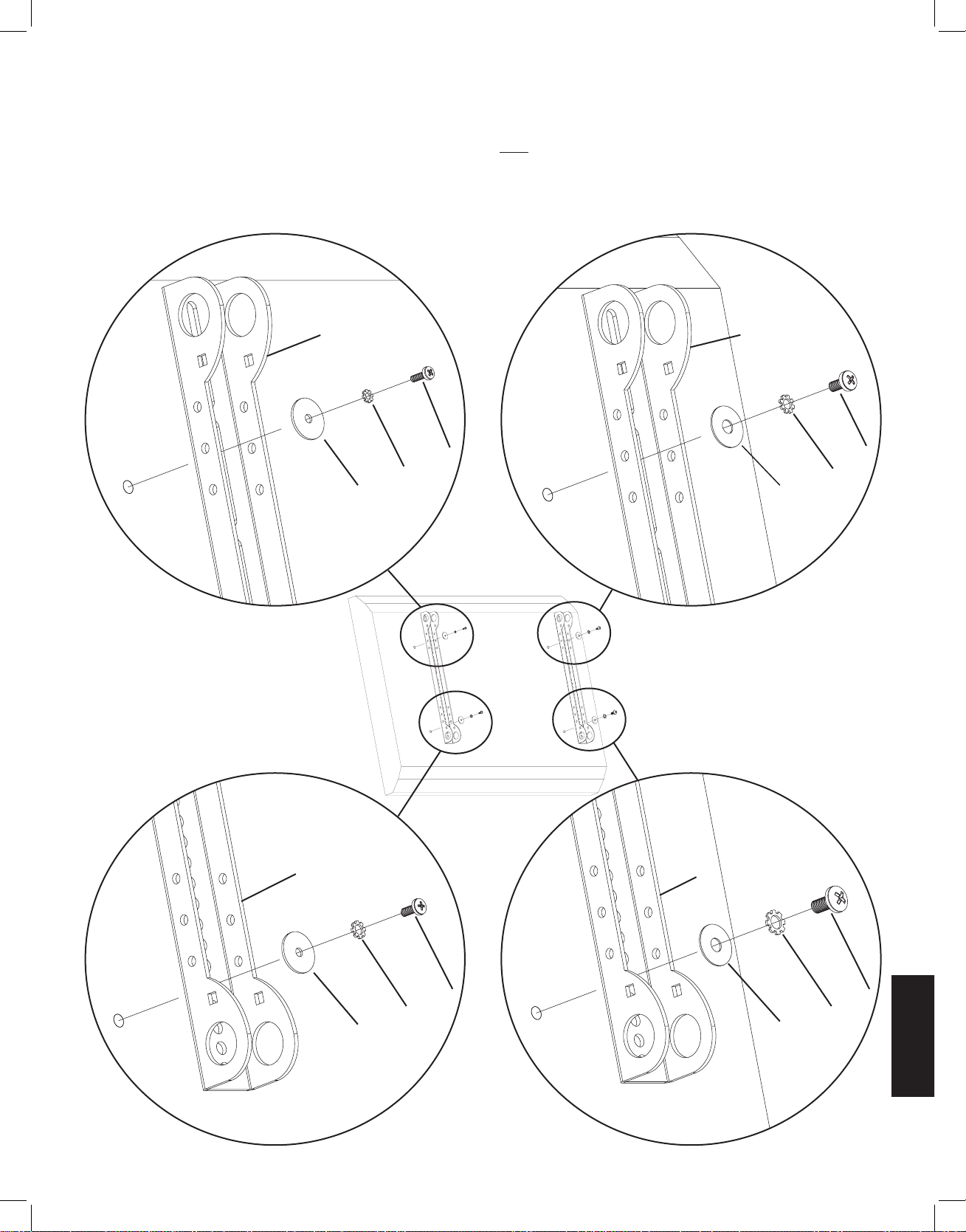
中文
步骤 1:将显示器架安装到背面平直的电视机上
首先,用手将螺钉 (n,o,p,q) 旋入电视机背面的螺孔以确定电视机所需螺钉的直径。如果遇到任何阻力,请立即停止!确定正确
的直径后,请查看如下相应图示。将螺钉依次旋入相应的锁紧垫圈 (v,w,x,y)、垫圈 (bb,cc) 和显示器架 (d),并最终旋入电视机
中。请确保两个显示器架垂直居中且相互齐平。重复这个步骤直到每个显示器架都使用两个螺钉固定在电视机上。
注意:对于曲背面或者背面不平的电视机,请参见步骤 2。完成该步骤后,继续步骤 3。
M4 直径螺钉 M6 直径螺钉
d d
n p
v x
bb cc
图 1
M5 直径螺钉 M8 直径螺钉
d d
o q
w y
bb cc
VMSAins_011206_ML.indd 61 1/16/06 5:22:31 PM
Page 62
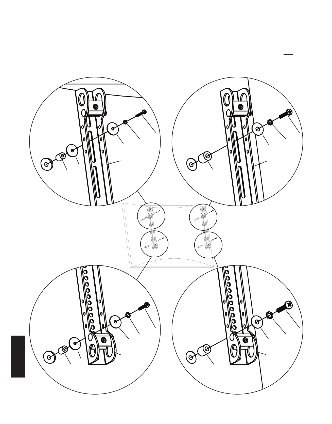
中文
步骤 2:将显示器架安装到曲背面或者任何其它背面不平的电视机上。
首先,用手将螺钉 (r,s,t,u) 旋入电视机背面的螺孔以确定电视机所需螺钉的直径。如果遇到任何阻力,请立即停止!确定正确的
直径后,请查看如下相应图示。将螺钉分别旋入相应的锁紧垫圈 (v,w,x,y)、垫圈 (bb,cc)、显示器架 (d)、第二块垫圈(bb - 仅限
M4/M5 直径)和间隔块 (z,aa),并最终旋入电视机中。请确保两个显示器架垂直居中且相互齐平。重复这个步骤直到每个显示
器架都使用两个螺钉固定在电视机上。
M4 直径螺钉 M6 直径螺钉
r t
v x
bb cc
d d
bb
z aa
图 2
M5 直径螺钉 M8 直径螺钉
s u
w y
bb cc
d d
bb
z aa
VMSAins_011206_ML.indd 62 1/16/06 5:22:31 PM
Page 63

中文
步骤 3:将虎钳组件安装到显示器架上:
注意:切勿将 1/4-20 螺母 (l) 旋得过紧。虎钳组件 (e) 应能绕着车身螺栓 (k) 自由旋转。
将虎钳组件 (e) 放置在显示器架 (d) 两侧边的中间,使虎钳的两个钳口分别对准 2.5 cm 直径孔并且使艾伦螺钉朝着背离电视
机的方向。然后将 2 英寸车身螺栓 (k) 依次穿过显示器架侧边上的方孔、虎钳组件上的孔和显示器架另一侧边上的方孔。最
后,将 1/4-20 螺母 (l) 从 2 英寸车身螺栓的末端旋入。重复此步骤在显示器架的底部进行安装。最后,对第二个显示器架重
复这两个操作步骤。参阅图 3 以获得帮助。
详细视图
图 3
钳口 e
k l
步骤 4:将臂组件安装到电视机上(第 I 部分)
警告:2.5 cm 直径管 (c) 必须伸出两个显示器架 (d) 的外侧边,且 6 个虎钳组件 (e) 上所有的艾伦螺钉都必须旋紧才能
确保安装的安全!
首先,调整每个虎钳组件 (e) 的方向,以便 2.5 cm 直径管 (c) 穿过显示器架 (d) 上的 2.5 cm 圆孔,然后再从虎钳组件的两
个钳口之间穿过。插入一根 2.5 cm 直径管,使其穿过第一个显示器架顶部的孔。重复此步骤在同一个显示器架的底部进行
操作。请参考图 4a 以获得帮助。
图 4a
e
c d
VMSAins_011206_ML.indd 63 1/16/06 5:22:32 PM
Page 64
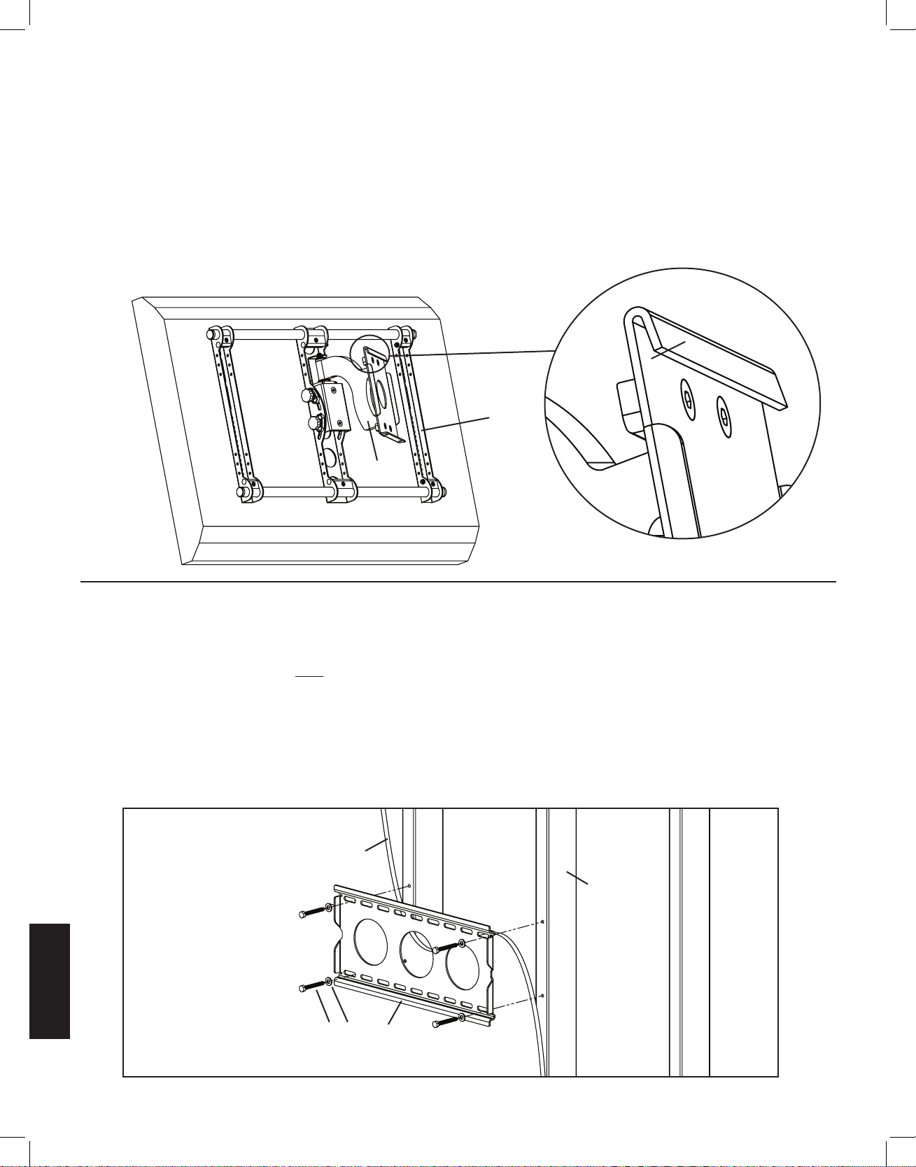
中文
步骤 4:将臂组件安装到电视机上(第 II 部分)
调整臂组件 (b) 使臂组件上的钩状突起朝上(如图 4b 的详细视图所示)。调整位于臂组件另一端的显示器架 (d) 上的两个
2.5 cm 直径孔,使其与 2.5 cm 直径管 (c) 处于同一条直线上。继续将 2.5 cm 直径管穿过臂组件上的虎钳组件,然后再穿过
另一个显示器架。继续确保臂组件和第二个显示器架上的虎钳组件的方向正确,使 2.5 cm 直径管在虎钳组件的钳口之间穿
过。2.5 cm 直径管放置到位后,即用内六角扳手 (j) 旋紧位于两个显示器架上四个虎钳组件的艾伦螺钉,将电视机牢牢地固
定在支架上。接下来,将臂组件滑动到两个显示器架之间所需的位置上,然后旋紧位于臂组件内侧的其余两个虎钳组件。
注意:Sanus 建议使臂组件位于两个显示器架的中间位置。
图 4b 详细视图
突起
d
b
b
步骤 5:安装墙板:仅限于木立筋安装选件。
警告:切勿将方头螺栓旋得过紧!旋紧方头螺栓 (h) 时,使方头螺栓垫圈 (i) 紧贴墙板 (a) 即可。
木立筋安装:墙板 (a) 必须安装在两根间距至少为 30.5 cm 的木立筋上。使用高品质墙筋传感器找到两根相邻墙筋的位置。
建议用锥子或细钉确定墙筋的位置。预先用 3/16 英寸钻头在每根墙筋的所需高度上钻出深度为 6.4 cm 的孔。请确保这些
孔位于墙筋的中心区域且相互齐平。以墙板为样板在每根墙筋上分别标出第二个孔的位置。用 3/16 英寸钻头在标记位置钻
出深度为 6.4 cm 的孔。然后用四个方头螺栓 (h) 和四片方头螺栓垫圈 (i) 将墙板安装到墙上。请确保墙板方向正确,即墙板
中央的平面如图 5 所示紧贴墙面。
图 5
去除石膏板露出墙筋位置
墙筋
h i a
VMSAins_011206_ML.indd 64 1/16/06 5:22:32 PM
Page 65

中文
步骤 6:将装配体挂到墙板上
警告:此步骤可能需要两个人才能抬起装配体并将其安装到墙板上!Sanus 对由此造成的受伤或损坏不承担任何责任。
调整臂组件 (b),使支臂伸展并远离电视机,并且使传递板与电视机平行。有些电视机需要两个人才能抬起!抬起装配体使
传递板钩住墙板 (a) 顶部的突起(如图 6a 所示)。在墙板上左右调整传递板至所需位置。将每个安全螺钉 (m) 分别旋入传
递板底部的两个孔中,并用内六角扳手 (j) 旋紧,从而使每个安全螺钉都位于墙板底部的突起之后,如图 6b 所示。
图 6a 图 6b
b
墙面 a
突起 突起
a
m
传递板
步骤 7:将显示器放置水平并调整张力
警告:请勿取下图 7 中标记的受拉螺母!
电视机安装到墙板 (a) 上并旋紧安全螺钉 (m) 后,便可将电视机调整至水平位置。稍微松动臂组件 (b) 背面的两个艾伦螺
钉。这两个螺钉松动后,以 ±6°调整电视机位置直至水平。电视机水平后,重新旋紧两个艾伦螺钉。只需倾斜电视机就可
调整其倾斜度。要调整倾斜拉力,请使用拉力旋钮。稍微旋松或旋紧图 7 中标记的受拉螺母可调整臂组件的紧度。如果需
要调整离电视机最近的受拉螺母,则必须取下安全支架,调整紧度,然后再重新装上安全支架(如图 7 的安全支架安装视
图所示)。
安全支架安装
图 7
受拉螺母
拉力旋钮 受拉螺母
艾伦螺钉
安全支架
VMSAins_011206_ML.indd 65 1/16/06 5:22:33 PM
Page 66

中文
步骤 8:理线
在开始理线之前,将电视机拉到离墙尽可能远的位置。使电缆略有松散,这样在移动过程中接头上就不会产生额外的张力。
理线扎带可装在多处,以免电线挡道。将扎线夹 (f) 向下按而将其安装到带座外球面轴承底部。扎线条 (g) 可安装到扎线夹
和任一个显示器架 (d) 的侧孔中。
详细视图
图 8
显示器架上的孔
带座外球面轴承
f
Sanus Systems 2221 Hwy 36 West, St. Paul, MN 55113 USA 11.15.05
客户服务:800.359.5520. 有关 Sanus 公司的其它产品,请登录公司网站 www.sanus.com
VMSAins_011206_ML.indd 66 1/16/06 5:22:33 PM
 Loading...