

Page 1
International Assembly Instructions for model VMPR1
ENGLISH
ESPAÑOL DEUTSCH FRANÇAIS ITALIANO PYCCKO
Spanish German French Italian Russian Japanese Mandarin
Sanus Systems 2221 Hwy 36 West, Saint Paul, MN 55113 USA 06.07.06
Customer Service: (800) 359-5520 • (651) 484-7988 • fax (651) 636-0367
Customer Service Europe: 31 (0)20 5708938 • fax 31 (0)20 5708989
See complementary Sanus products at www.sanus.com
中文
Page 2

Page 3
Assembly Instructions for Model: VMPR1
Thank you for choosing a Sanus Systems Model: VMPR1 ceiling mount. The VMPR1 ceiling mount provides a unique, simplied method
of ceiling mounting inverted LCD/DLP projectors. Its low prole design offers roll, pitch, and yaw adjustment. The VMPR1 steel-to-steel
construction with adjustable height to maintain proper ventilation, hold registration for quick lamp changes and easy lter cleaning without
loosing registration. The VMPR1 ceiling mount includes an NPT Extension Pipe that may be used where more room is required, such as
areas with vaulted or cathedral ceilings.
WARNING: The maximum weight to be installed on the VMPR1 ceiling mount is 50 pounds [22.68 Kg]. Improper installation may
result in serious personal injury. Make sure the structural members can support a redundant weight factor ve times the total
weight of the equipment. If the structure can not support this weight, reinforce the structure prior to installing the VMPR1.
If you do not understand these directions, or have any doubts about the safety of the installation, please call a qualied contractor or
contact Sanus at 800.359.5520 or www.sanus.com. Check carefully to make sure that there are no missing or defective parts. Our
customer service representatives can quickly assist you with installation questions and missing or damaged parts. Replacement parts
for products purchased through authorized dealers will be shipped directly to you. Never use defective parts. Do not use this product
for any purpose that is not explicitly specied by Sanus Systems. Please call Sanus Systems before returning products to the point of
purchase.
CSAV, Inc. and its afliated corporations and subsidiaries (collectively, “CSAV”), intend to make this manual accurate and complete.
However, CSAV makes no claim that the information contained herein covers all details, conditions, or variations. Nor does it provide for
every possible contingency in connection with the installation or use of this product. The information contained in this document is subject to change without notice or obligation of any kind. CSAV makes no representation of warranty, expressed or implied, regarding the
information contained herein. CSAV assumes no responsibility for accuracy, completeness or sufciency of the information contained in
this document.
ENGLISH
Required Tools: Open End Wrenches, Phillips screwdrivers, Allen Wrenches (provided), other tools may be required depending on the
method of installation.
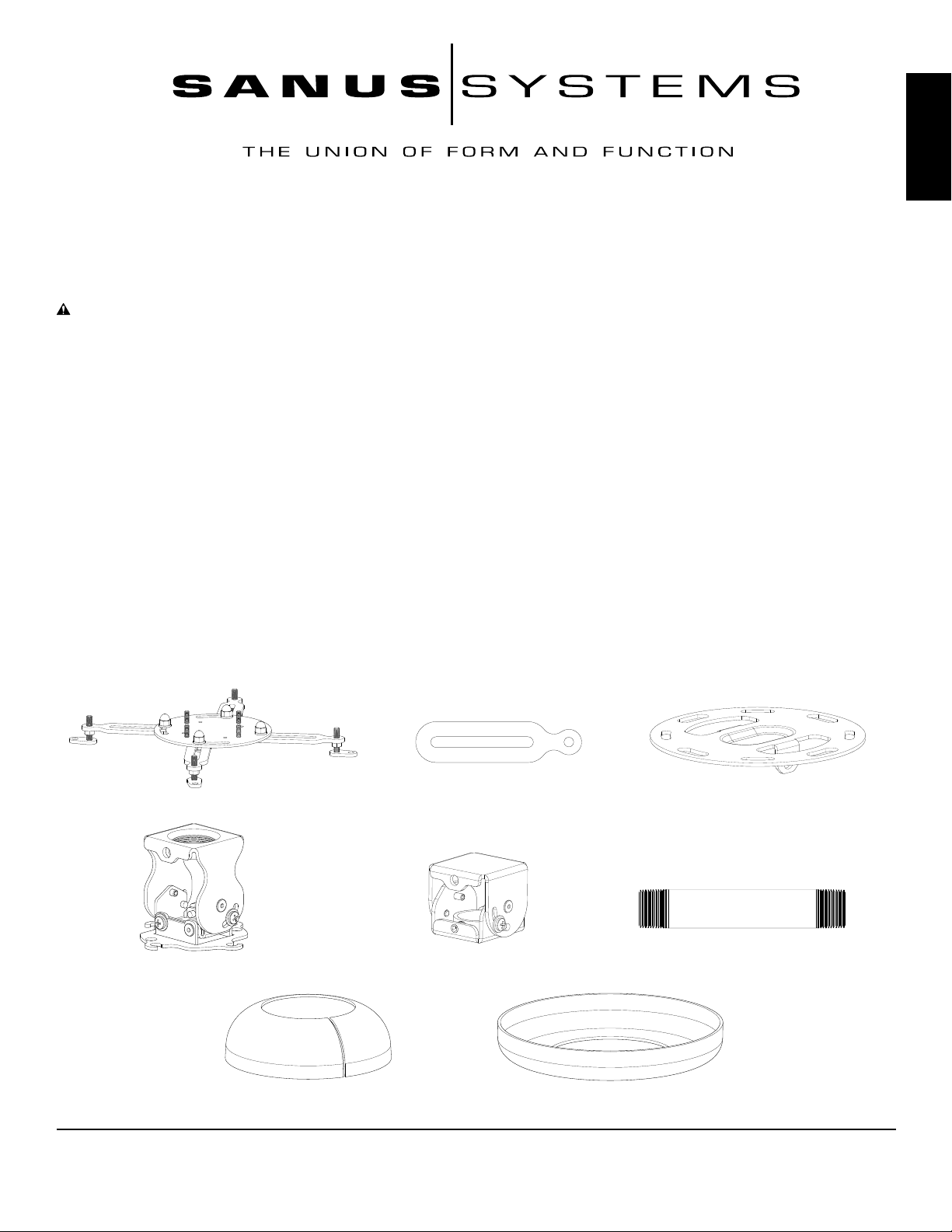
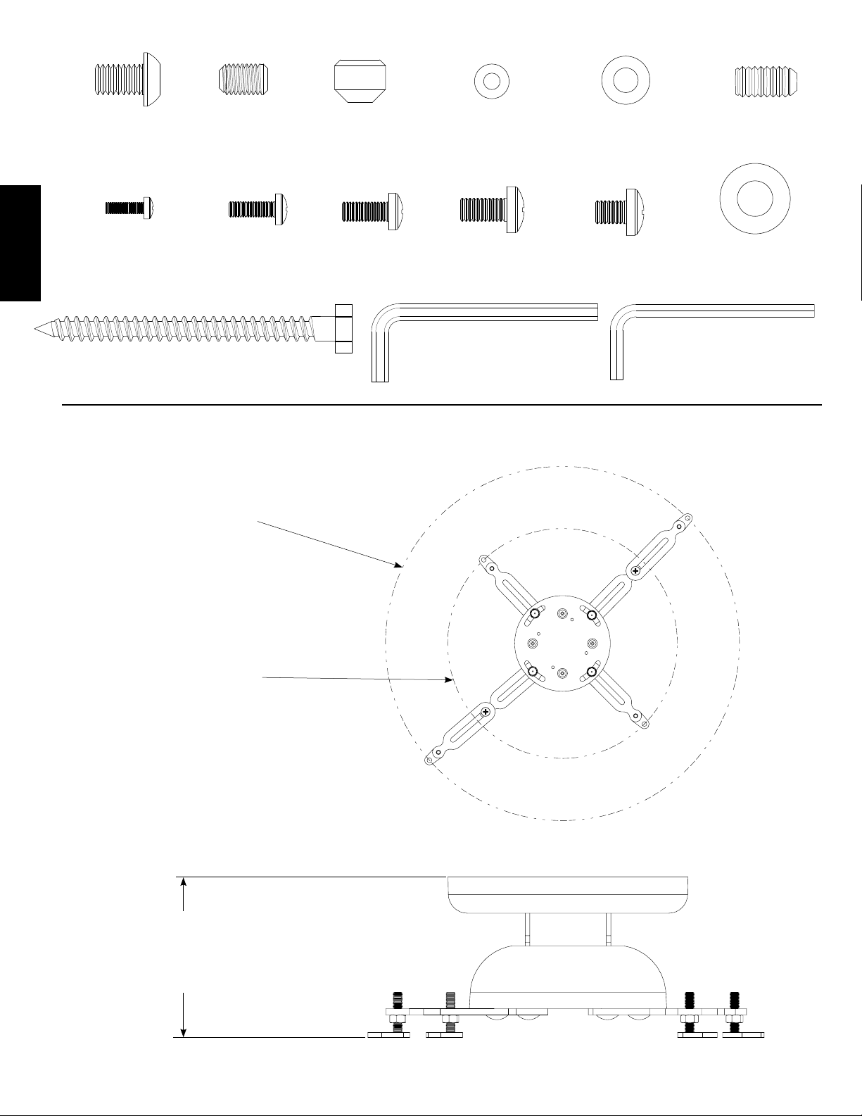
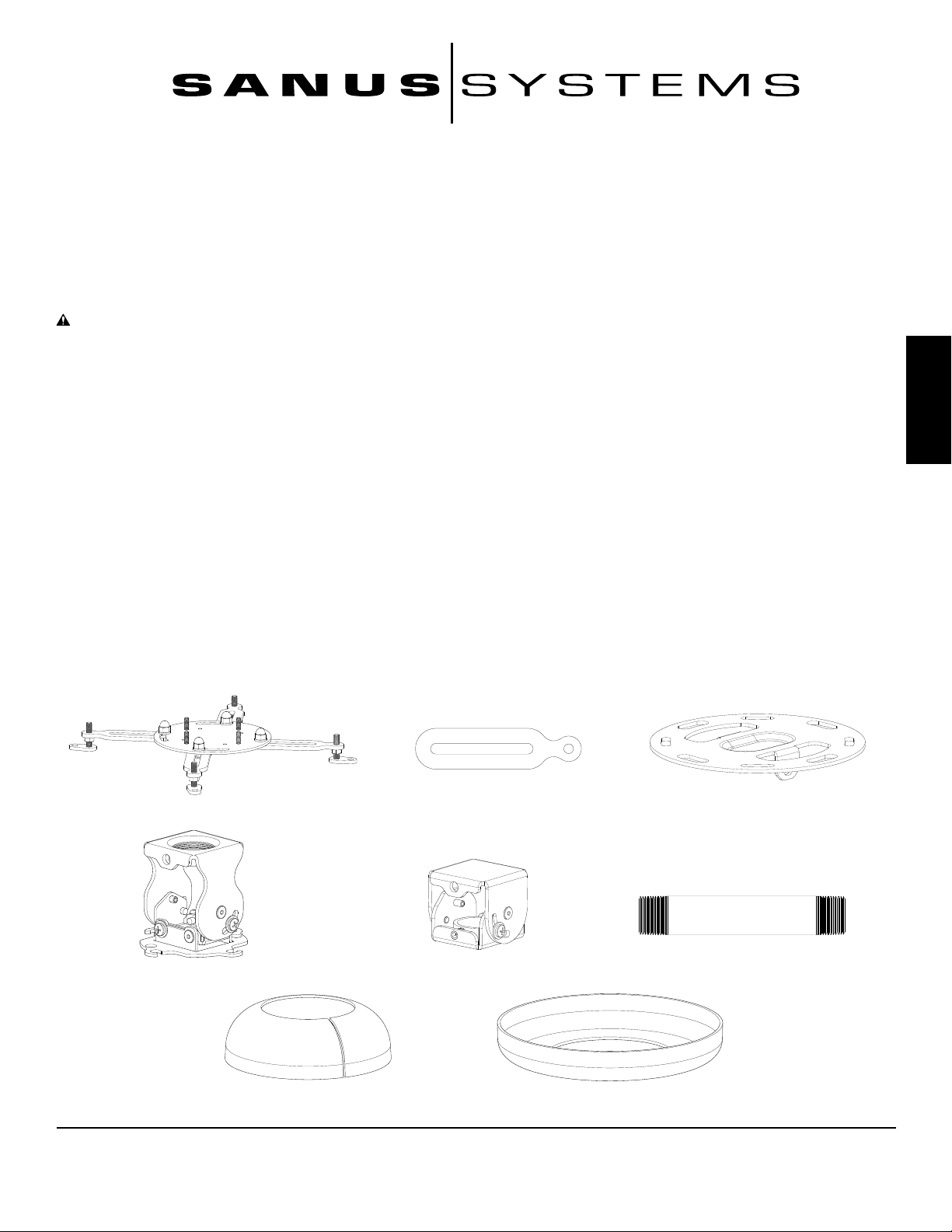
Supplied Parts and Hardware: (All threaded fasteners are shown full size.)
Universal Projector Interface - A
Qty. 1
Adjustment Bracket - D
Qty. 1
Extension Arm - B
Qty. 2
NPT Adapter - E
Qty. 1
Ceiling Plate - C
Qty. 1
NPT Extension Pipe - F
Qty. 1
Bottom Cover - G
Qty. 1
Top Cover - H
Qty. 1
Sanus Systems 2221 Hwy 36 West, Saint Paul, MN 55113 USA (6901-100023)
Customer Service: 800.359.5520. See complementary Sanus products at www.sanus.com
Page 4
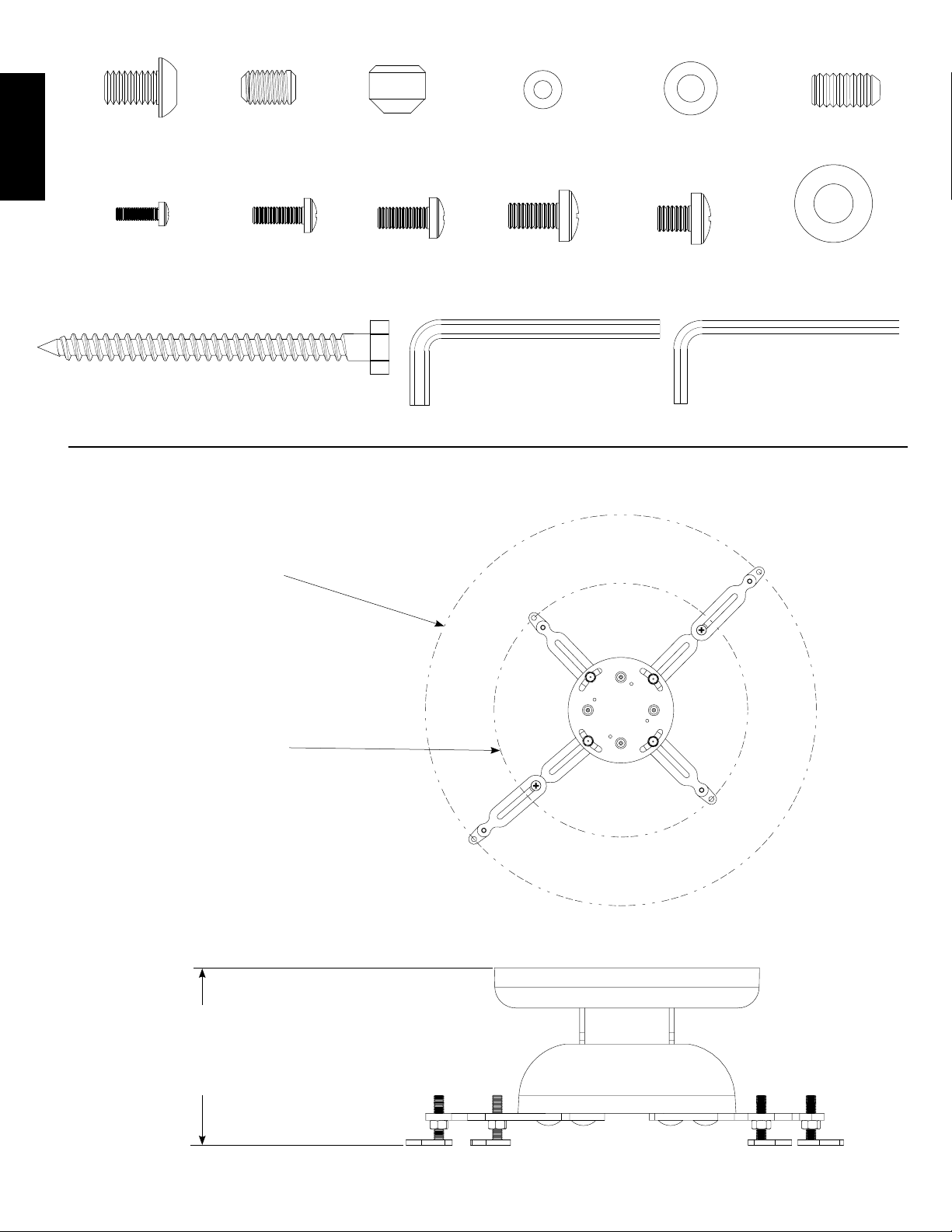
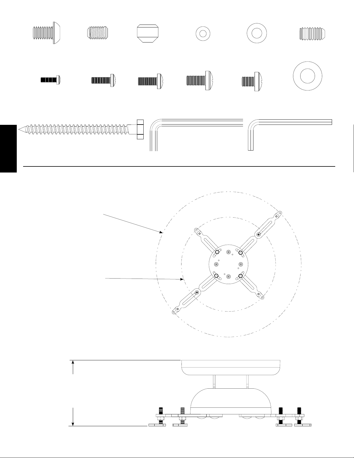
Cap Screw - I
Qty. 1
ENGLISH
Set Screw - J
Qty. 1
Tapered Nut - K
Qty. 4
M3/M4 Washer - L
Qty. 4
M5/M6 Washer - M
Qty. 4
Set Screw - N
Qty. 1
M3 x 10 mm - O
Qty. 4
VMPR1 Dimensional Drawings
[470.15 mm]
Covering area with
Extension Arms (B)
M4 x 12 mm - P
Qty. 4
Lag Bolt - U
Qty. 2
18.51 in
installed
M5 x 12 mm - Q
Qty. 4
M6 x 12 mm - R
Qty. 4
Allen Key - V
Qty. 1
M6 x 8 mm - S
Qty. 2
Lag Bolt Washer - T
Qty. 2
Allen Key - W
Qty. 1
[305.07 mm]
12.01 in
Covering area without
Extension Arms (B)
installed
[117.348 mm]
4.62 in
TO
[100.076 mm]
3.94 in
Page 5
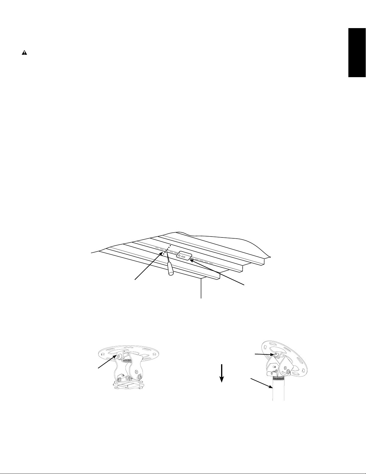
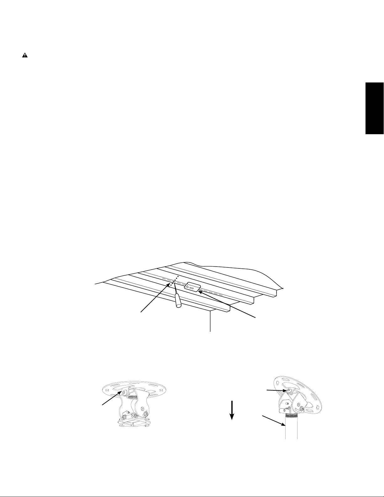
Step 1: Ceiling Preparation
NOTE: Study the following information and adapt it as necessary to t your specic installation.
WARNING: The maximum weight to be installed on the VMPR1 ceiling mount is 50 pounds [22.68 Kg]. Improper
installation may result in serious personal injury. Make sure the structural members can support a redundant
weight factor ve times the total weight of the equipment. If the structure can not support this weight, reinforce the
structure prior to installing the VMPR1.
Determine the position of the mount and its distance from the screen. This will require knowing the lens to screen distance.
This information is normally listed in the projector specications for set-up.
The hardware provided with the VMPR1 is designed to be secured to a wood framing member. For installations other than
this, consult a qualied contractor. Use a high quality Stud Sensor to locate a stud in the area that you plan to mount the
VMPR1 as shown in Diagram 1A. Verify the stud location with an awl or thin nail.
NOTE: Do not attach the Ceiling Plate (C) at this time.
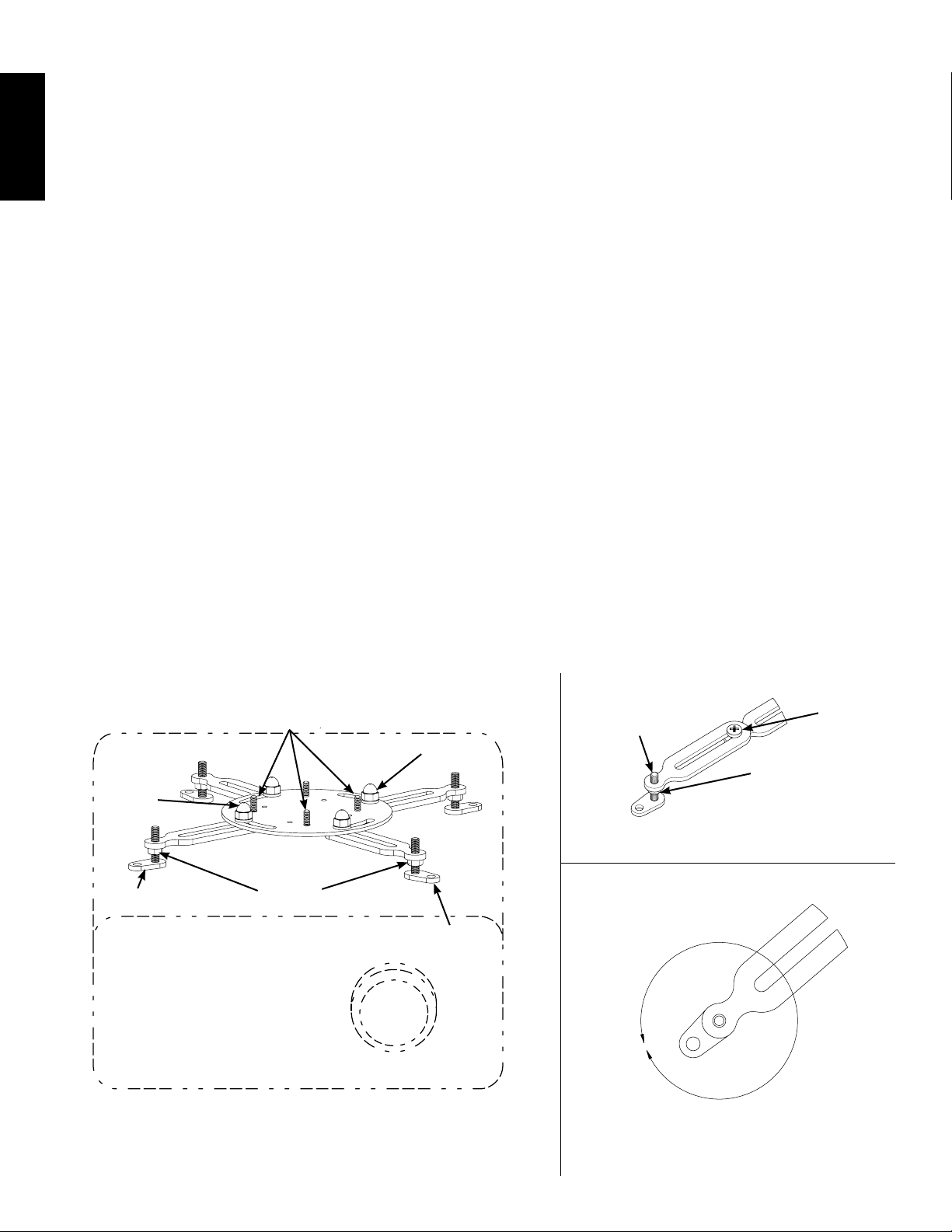
Flat Ceilings: Align the Ceiling Plate (C) with the two tabs aligned to the screen as shown in Diagram 1B.
Pre-drill a 3 in [76.2 mm] deep hole in the center of the framing member using a 3/16 in drill; then, using the Ceiling Plate
(C) as a template, pre-drill a second hole to the same depth.
Cathedral or Vaulted Ceilings: Align the Ceiling Plate (C) so that the NPT Adapter (E) is angled to allow the NPT Extension
Pipe (F) to point straight down as shown in Diagram 1C.
ENGLISH
Pre-drill a 3 in [76.2 mm] deep hole in the center of the framing member using a 3/16 in drill; then, using the Ceiling Plate
(C) as a template, pre-drill a second hole to the same depth.
Diagram 1A
Use awl or thin nail
to verify center of
framing member.
(Shown assembled
for reference only.)
Tab toward screen
to allow adequate
Pitch Adjustment.
Diagram 1B
Tab aligned to allow
NPT Extension Pipe (F)
to point down.
Use Stud Sensor
to locate framing
member.
Diagram 1C
(Shown assembled
for reference only.)
F
Page 6
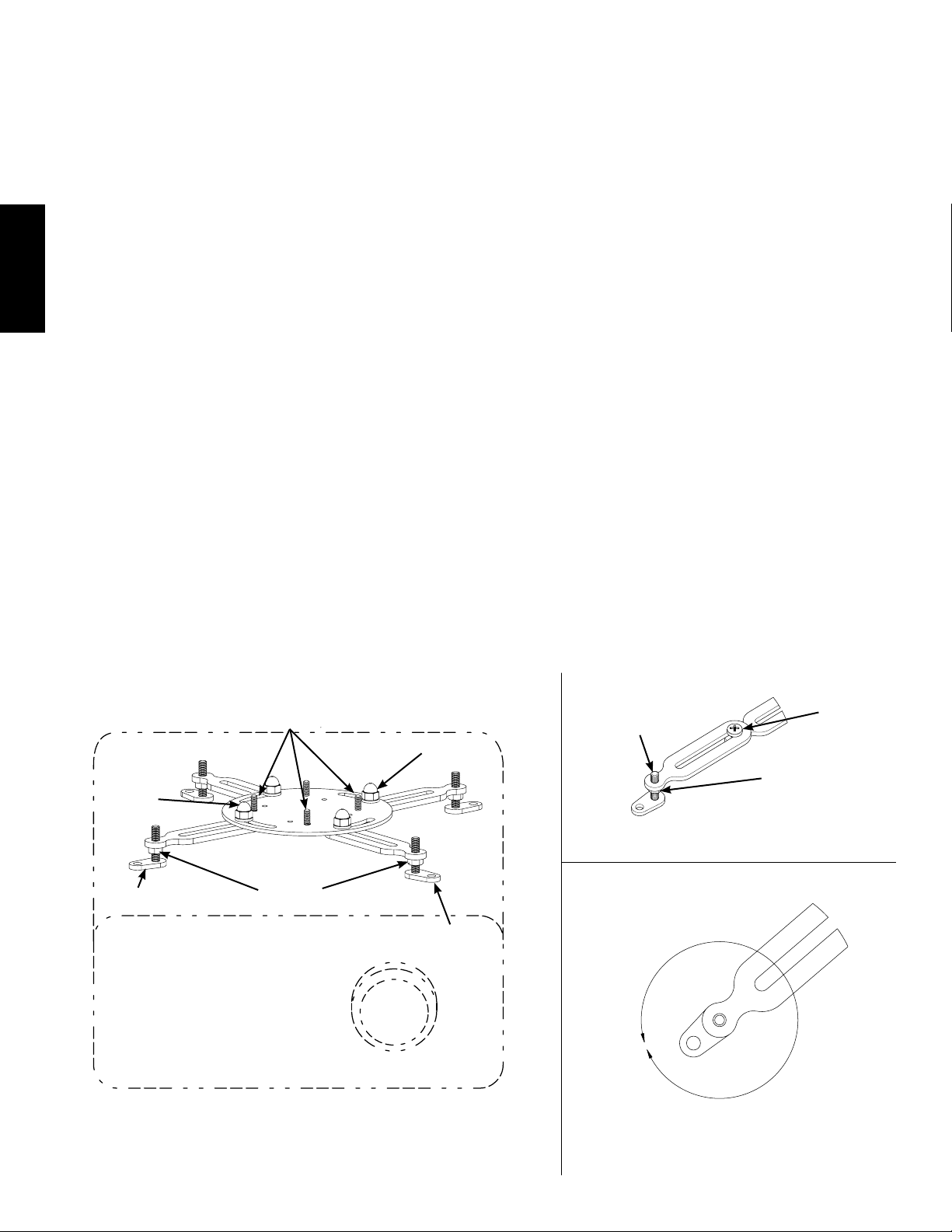
Step 2: Attach Universal Projector Interface to Projector
Loosen, but do not remove the Acorn Nuts shown in Diagram 2A.
Place the Universal Projector Interface (A) on the projector, aligning the holes in the Adjustable Feet with the threaded holes
in the projector and with the Threaded Studs in line as shown in Diagram 2A. If there are only three mounting points, remove
one Leg from the Universal projector Interface by removing the Acorn Nut.
ENGLISH
If necessary, add Extension Arms (B) to the Universal Projector Interface (A) by removing the Adjustable feet and Installing
them on the Extension Arms as shown in Diagram 2B.
Secure the Extension Arms (B) to the Universal Projector Interface, using the M6 x 8 mm (S) screws as shown in
Diagram 2B.
Adjust the Adjustable Feet as shown in Diagram 2C, making sure to allow for proper air ventilation and keeping the Universal
Projector Interface level with the projector. Some Adjustable Feet may need to be at different heights.
NOTE: If the mounting holes are closer than a ve inch diameter, lower the feet all the way to allow the Threaded
Stud to swing under the Ceiling Plate (C).
Determine the proper screw size and depth, M3 x 10 mm (O), M4 x 12 mm (P), M5 x 12 mm (Q), or M6 x 12 mm (R), and
corresponding Washers (L, M) for projector mounting.
Using correct Screws (O,P,Q,R) and Washers (L,M), secure the back two legs of the Universal Projector Interface (A) to the
projector; then, secure the front legs.
Move the Universal Projector Interface (A) to the center of gravity of the projector. You can locate the center of gravity by
attempting to lift the projector straight up. If it feels like it wants to twist, move the Universal Projector Interface toward the
heavy side. When the projector feels balanced, you have located the center of gravity.
Tighten the Acorn Nuts securing the Legs; then snug up the Hex Nuts on the Adjustable Feet.
Diagram 2A Diagram 2B
Acorn
Nut
Adjustable
Foot
Threaded
Studs
Hex Nut
on all
Adjustable Feet
Acorn
Nut
Adjustable
Foot
Remove
Adjustable Foot
and install here
Hex Nut
on all
Adjustable Feet
Diagram 2C
Install
M6 x 8 mm
Screw (S)
Rotate Adjustable Foot left or
right to increase or decrease
length. Each rotation equals
0.625" [15.875 mm].
Page 7
Step 3A: Attach Ceiling Plate to Adjustment Bracket - Flat Ceilings
NOTE: If the projector is being mounted in an area where it must be lower from the ceiling, such as areas with vaulted
or cathedral ceilings, proceed directly to Step 3B - Attach Ceiling Plate to Adjustment Bracket using Extension Pipe
and NPT Adapter - Vaulted or Cathedral Ceilings.
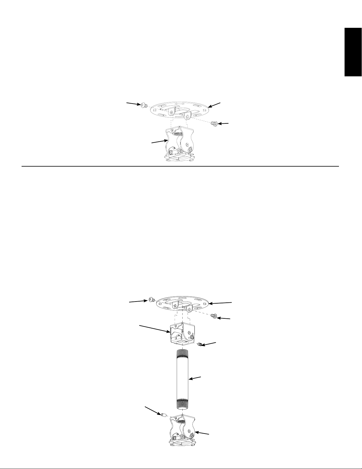
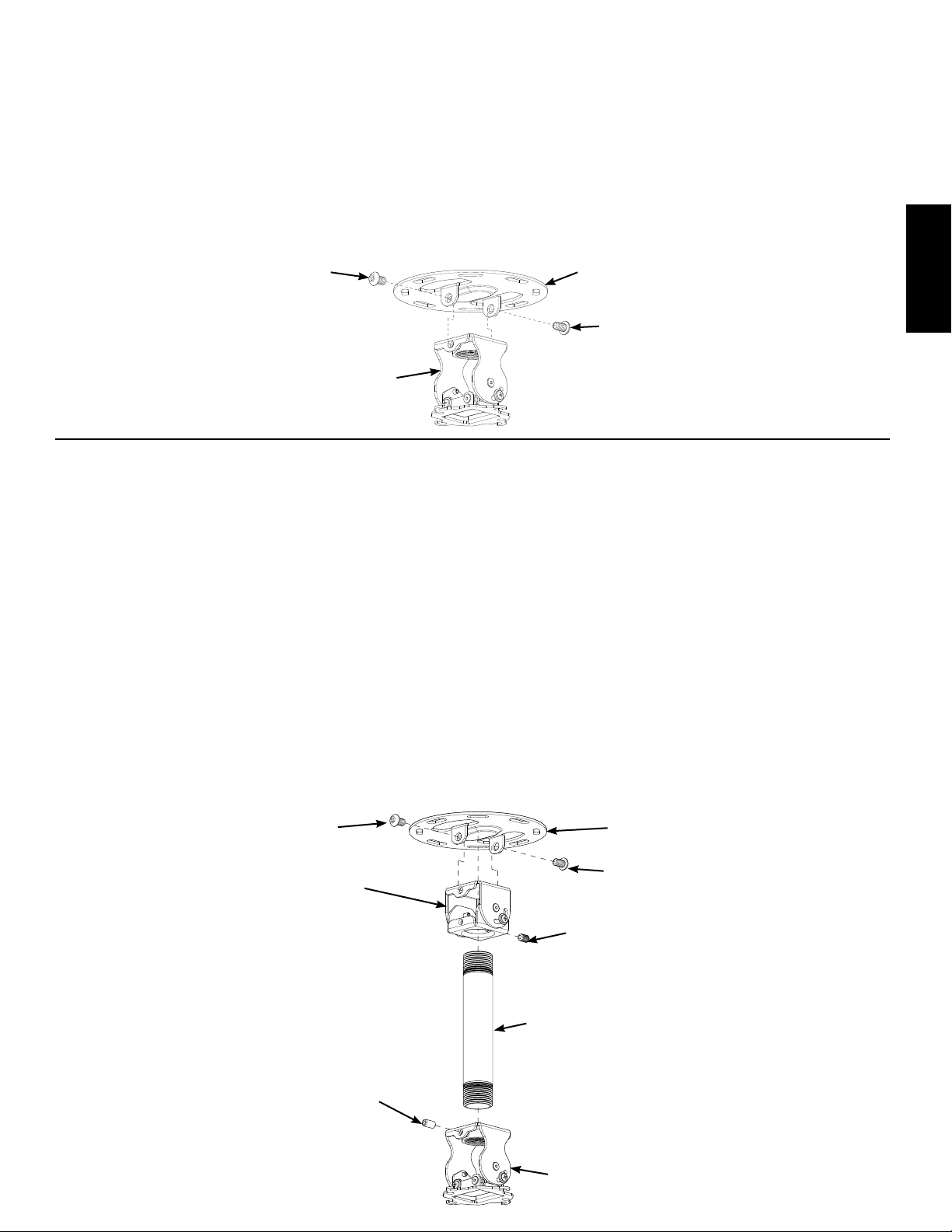
Place the Ceiling Plate (C) over the Adjustment Bracket (D), lining up the holes in both the Ceiling Plate and the Adjustment
Bracket as shown in Diagram 3A; then, using the two Cap Screws (I) secure the Adjustment Bracket to the Ceiling Plate.
Using the Allen Key (V) and the two Cap Screws (I), secure the Ceiling Plate (C) to the Adjustment Bracket (D).
Diagram 3A
I
D
Step 3B: Attach Ceiling Plate to Adjustment Bracket using Extension Pipe and NPT Adapter - Vaulted or Cathedral Ceilings
Place the Ceiling Plate (C) over the NPT Adapter (E), lining up the holes in both the Ceiling Plate and the NPT Adapter as
shown in Diagram 3B.
C
I
ENGLISH
Using the Allen Key (V) and the two Cap Screws (I), secure the Ceiling Plate (C) to the NPT Adapter (E).
NOTE: Set Screw (J) is shorter than Set Screw (N).
NOTE: When using the NPT Extension Pipe (F), the Set Screw (N) must point either toward or away from the screen.
If a longer NPT Extension Pipe is required, custom lengths may be purchased from your local hardware store.
Thread the NPT Extension (F) into the NPT Adapter (E) and secure it with the Set Screw (J) as shown in Diagram 3B.
Thread the Adjustment Bracket (D) onto the NPT Extension (F); then, using Set Screw (N), secure the Adjustment Bracket
(D) to the NPT extension (F) as shown in Diagram 3B.
Diagram 3B
I
E
F
C
I
J
N
D
Page 8
Step 4A: Attach VMPR1 Top Assembly to Ceiling and install Top Cover - Flat Ceilings
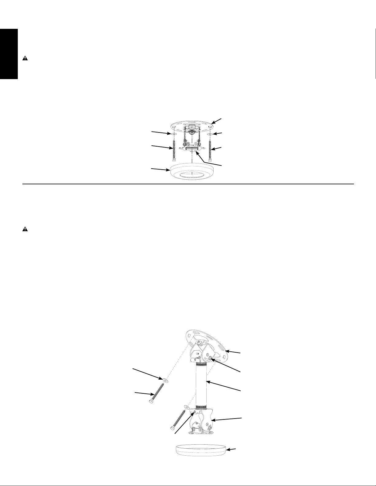
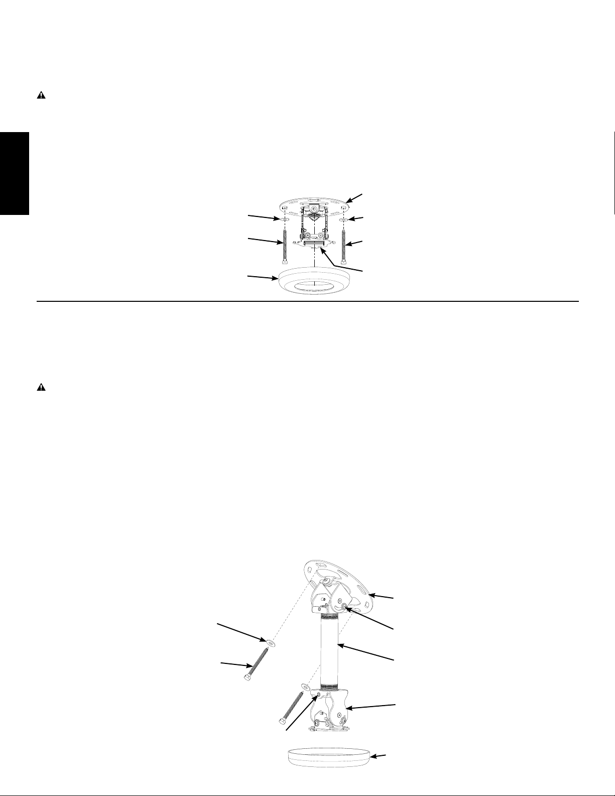
Using the Lag Bolts (U) and Lag Bolt Washers (T) secure the VMPR1 Top Assembly to the framing member at the location
selected in Step 1: Ceiling Preparation.
CAUTION: Do not over tighten the lag Bolts (U). Tighten lag Bolts until they are pulled rmly against the ceiling
Plate (C). If there is a layer of drywall or other material, this drywall or other material may not exceed 5/8 inch (15.8
ENGLISH
mm) in thickness. Failure to heed this caution may result in property damage and/or personal injury.
Tighten the Lag Bolts (U) until the Ceiling Plate (C) is ush with the ceiling drywall.
Choose the desired color Top Cover (H) and simply slide it over the Adjustment Bracket (D) until it ts snugly onto the Ceiling
Plate (C).
Diagram 4A
C
T
U
H
Step 4B: Attach VMPR1 Top Assembly to Ceiling and install Top Cover - Vaulted or Cathedral Ceilings
Using the Lag Bolts (U) and Lag Bolt Washers (T) secure the VMPR1 Top Assembly to the framing member at the location
selected in Step 1: Ceiling Preparation.
CAUTION: Do not over tighten the lag Bolts (U). Tighten lag Bolts until they are pulled rmly against the ceiling
Plate (C). If there is a layer of drywall or other material, this drywall or other material may not exceed 5/8 inch (15.8
mm) in thickness. Failure to heed this caution may result in property damage and/or personal injury.
Tighten the Lag Bolts (U) until the Ceiling Plate (C) is ush with the ceiling drywall.
Loosen the Pitch Adjustment Screws on the NPT Adapter (E) and set the NPT Extension Pipe (F) so that it is facing down;
then, retighten the Pitch Adjustment Screws.
Rotate the Adjustment Bracket (D) until the Set Screw (N) is facing the screen; then, tighten the Set Screw securing the
Adjustment Bracket to the NPT Extension Pipe (F).
T
U
D
Choose the desired color Top Cover (H) and simply slide it over the Adjustment Bracket (D) until it ts snugly onto the Ceiling
Plate (C).
Diagram 4B
C
T
U
N
E
F
D
H
Page 9
Step 5: Add Projector
Once the desired position is located and all the Adjustment Screws are tightened, the projector may be removed for service
and re-installed without losing registration by reversing the following procedure.
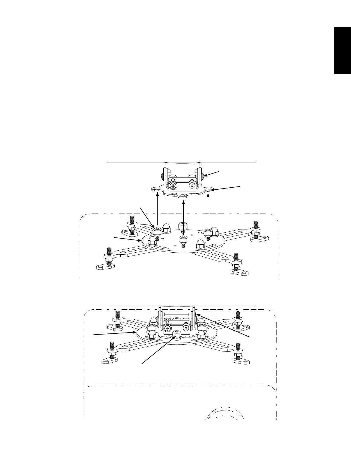
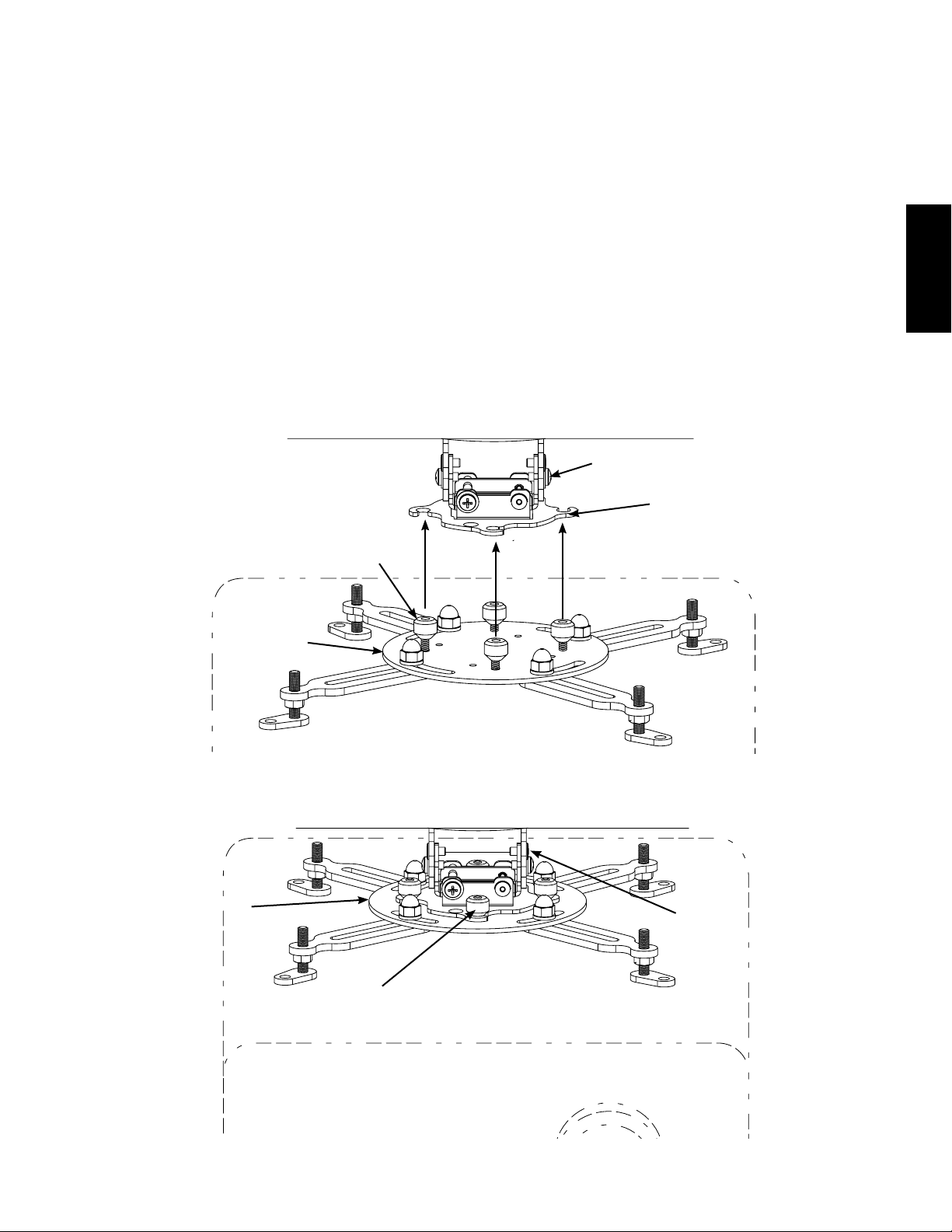
Loosely install the Tapered Nuts (K) with the tapered end down on the Studs of the Universal Projector Interface (A) as
shown in Diagram 5A.
NOTE: The two halves of the VMPR1 attach by lifting the and rotating the Universal Projector Interface (A) so
that the Threaded Studs with Tapered Nuts (K) rotate into the Vee Slots of the Adjustment Bracket (D) as shown
in Diagram 5A. Once the desired position is located and the Tapered Nuts are tightened, the projector may be
removed for service and re-installed without losing registration by simply rotating the projector.
Align the four Vee Slots of the Adjustment Bracket (D) with the Threaded Studs and Tapered Nuts (K) of the Universal
Projector Interface (A); then, rotate the Universal Projector Interface until it is securely locked into the Vee Slots of the
Adjustment Bracket (D).
Tighten the Tapered Nuts (K), securing the projector and Universal Projector Interface (A) to the Adjustment Bracket (D) as
shown in diagram 5B.
Diagram 5A
D
Vee Slot
ENGLISH
K
A
Diagram 5B
A
K
D
Page 10
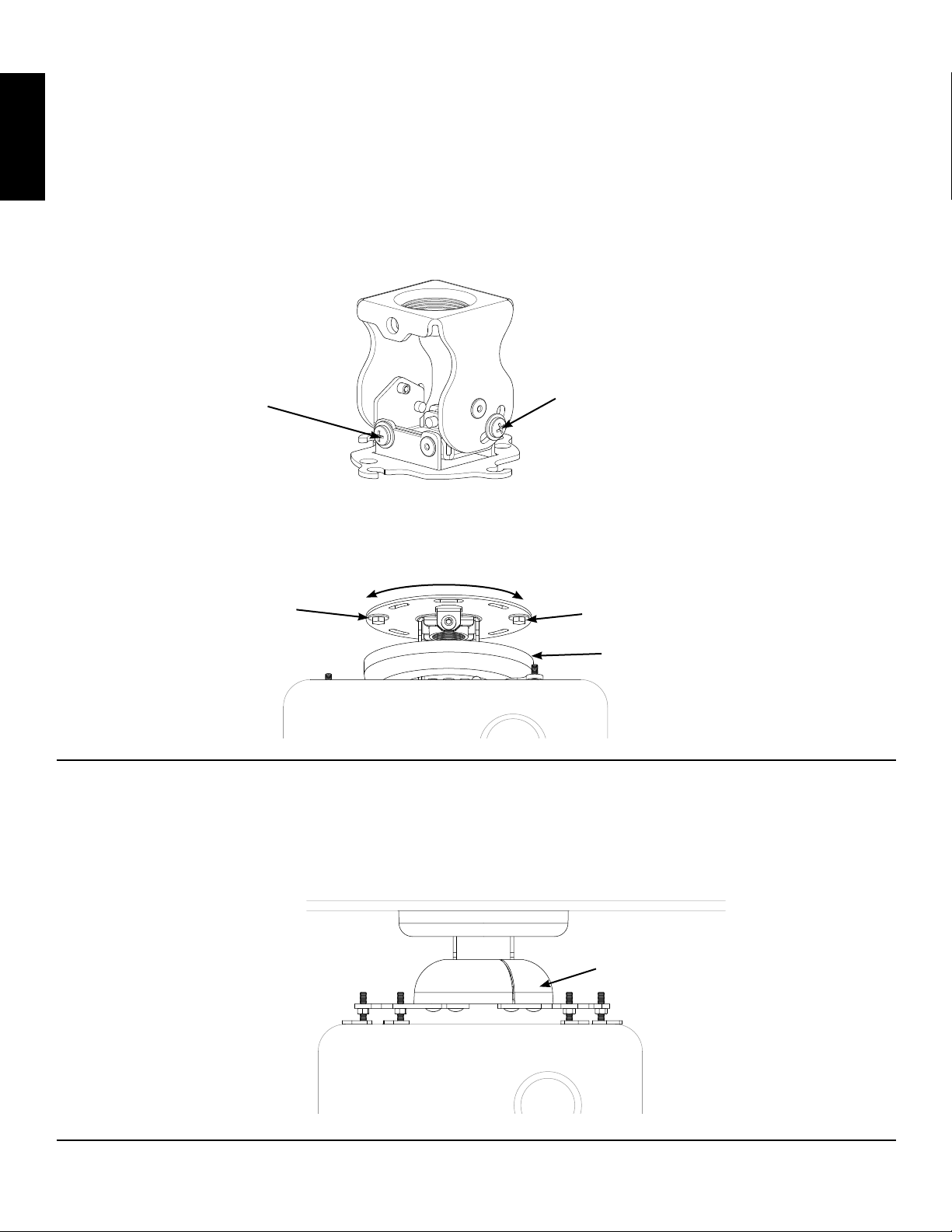
Step 6 - Projector Alignment
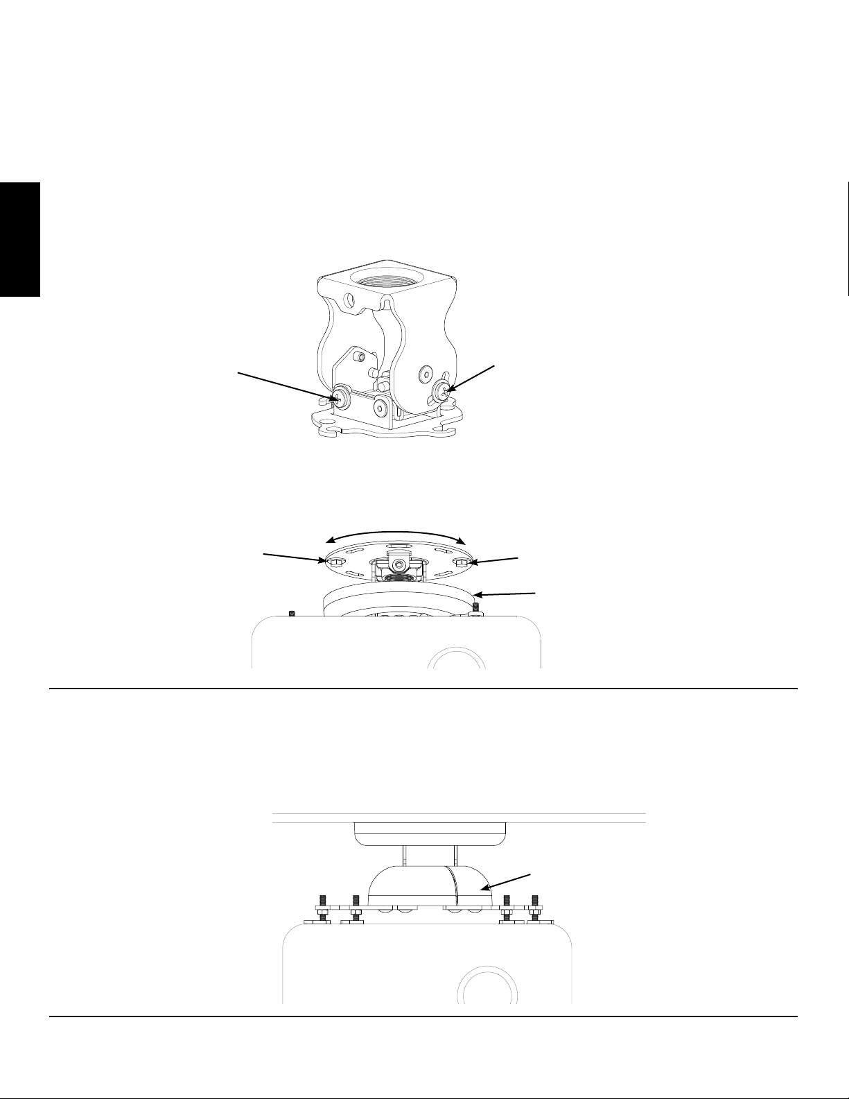
The VMPR1 can be adjusted for vertical elevation (Pitch), horizontal tilt (Roll), and rotation (Yaw).
Pitch Adjustment
Loosen the Pitch Adjustment Screws on both sides of the Adjustment Bracket (D) and adjust the projector to the desired
Pitch; then, retighten the Pitch Adjustment Screws as shown in Diagram 6A.
ENGLISH
Roll Adjustment
Loosen the Roll Adjustment Screws on both sides of the Adjustment Bracket (D) and adjust the projector to the desired angle
and tilt; then, retighten the Roll Adjustment Screws as shown in Diagram 6A.
Diagram 6A
Roll Adjustment Screw
Yaw Adjustment
Lower the Top Cover (H) to expose the Lag Bolts (U). Loosen the Lag Bolts and adjust the projector to the desired angle or
yaw; then retighten the Lag Bolts and snap the Top Cover (H) back into place as shown in Diagram 6B.
Diagram 6B
Lag Bolt (U)
Step 7 - Attach Bottom cover
Flex the Bottom Cover (G) at the seam, just enough to t it around the Adjustment Bracket (D). Align the seam in the least
visible location, you may also stick a small piece of tape to the inside of the Bottom cover to secure the seam.
Pitch Adjustment Screw
Lag Bolt (U)
Top Cover (H)
Diagram 7
Sanus Systems 2221 Hwy 36 West, Saint Paul, MN 55113 USA (6901-100023)
Customer Service: 800.359.5520. See complementary Sanus products at www.sanus.com
G
Page 11

Instrucciones de ensamblaje del modelo: VMPR1
Gracias por elegir un modelo de Sanus Systems: El soporte de cielorraso VMPR1. El soporte de cielorraso VMPR1 brinda un método único y
simplicado de montar proyectores invertidos LCD/DLP en el cielorraso. Su diseño de bajo perl ofrece un ajuste del desplazamiento, del grado y
del ángulo de inclinación. La construcción de acero-a-acero del VMPR1 con una altura ajustable para mantener la ventilación correcta, mantiene
el registro para cambios rápidos de bombilla y una limpieza fácil del ltro sin perder el registro. El soporte de cielorraso VMPR1 incluye un tubo de
extensión NPT que puede utilizarse en lugares donde se requiere más espacio; por ejemplo, en áreas con cielos rasos abovedados o tipo catedral.
ADVERTENCIA: El peso máximo que se puede instalar sobre el soporte de cielorraso VMPR1 es de 22,7 kg. La instalación
incorrecta puede resultar en lesiones personales graves. Asegurarse de que los componentes estructurales puedan soportar
un factor de peso redundante de cinco veces el peso total del equipo. Si la estructura no puede soportar este peso, reforzar la
estructura antes de instalar el modelo VMPR1.
Si no entiende estas instrucciones o si tiene alguna duda con respecto a la seguridad de la instalación, llame a un contratista cualicado
o comuníquese con Sanus llamando al 800.359.5520 (en EE.UU.) o al 31 (0) 20 5708938 (en Europa). Puede también visitar nuestro
sitio web en www.sanus.com. Revise cuidadosamente los productos para asegurarse de que ninguna pieza falte ni presente defectos.
Nuestros representantes del servicio de atención al cliente le ofrecerán asistencia inmediata con cualquier duda sobre la instalación o
con respecto a piezas faltantes o dañadas. Las piezas de repuesto para los productos comprados a través de un distribuidor autorizado
se enviarán directamente a usted. Nunca use piezas defectuosas. No utilice este producto para nes no explícitamente especicados
por Sanus Systems. Llame a Sanus Systems antes de devolver los productos al punto de compra.
CSAV, Inc. y sus empresas y subsidiarias (colectivamente, “CSAV”), tienen la intención de que este manual sea preciso y completo. Sin embargo,
CSAV no asegura que la información contenida en éste cubra todos los detalles, condiciones o variaciones. Tampoco asegura que el mismo provea
todas las contingencias posibles en relación a la instalación o uso de este producto. La información contenida en este documento está sujeta a
cambios sin aviso u obligación de ningún tipo. CSAV no se hace parte de garantías, expresas o implícitas, con respecto a la información aquí
contenida. CSAV no asume responsabilidad alguna por la precisión, integridad o suciencia de la información contenida en este documento.
Herramientas necesarias: Llaves de tuerca de boca abierta, destornilladores Phillips, llaves allen (suministradas); es posible que se
requieran otras herramientas dependiendo del método de instalación.
ESPAÑOL
Piezas y tornillería suministradas: (Todos los sujetadores roscados se muestran en tamaño real.)
Interconexión de proyector universal - A
Cantidad: 1
Soporte de ajuste - D
Cantidad: 1
Cubierta inferior - G
Cantidad: 1
Brazo de extensión - B
Cantidad: 2
Adaptador NPT - E
Cantidad: 1
Cubierta superior - H
Tubo de extensión NPT - F
Cantidad: 1
Placa de cielorraso - C
Cantidad: 1
Cantidad: 1
Sanus Systems 2221 Hwy 36 West, Saint Paul, MN 55113 USA (6901-100023)
Servicio de atención al cliente: 800.359.5520. Vea los productos complementarios de Sanus en el sitio www.sanus.com
Page 12
Tornillo
prisionero - I
Cantidad: 1
Tornillo
prisionero - J
Cantidad: 1
Tuerca
abocinada - K
Cantidad: 4
Arandela
M3/M4 - L
Cantidad: 4
Arandela
M5/M6 - M
Cantidad: 4
Tornillo
prisionero - N
Cantidad: 1
M3 x 10 mm - O
Cantidad: 4
M4 x 12 mm - P
Cantidad: 4
ESPAÑOL
Tirafondo - U
Cantidad: 2
Diagramas dimensionales del VMPR1
[47 cm]
18,51 pulgadas
Área de cobertura con
brazos de extensión (B)
instalados
[30,5 cm]
12,01 pulgadas
Área de cobertura sin
brazos de extensión (B)
instalados
M5 x 12 mm - Q
Cantidad: 4
M6 x 12 mm - R
Cantidad: 4
Llave allen - V
Cantidad: 1
M6 x 8 mm - S
Cantidad: 2
Arandela para
tirafondo - T
Cantidad: 2
Llave allen - W
Cantidad: 1
[11,7 cm]
4,62 pulgadas
A
[10,01 cm]
3,94 pulgadas
Page 13
Paso 1: Preparación del cielorraso
NOTA: Estudiar la siguiente información y adaptarla según sea necesario para que se ajuste a la instalación especíca.
ADVERTENCIA: El peso máximo que se puede instalar sobre el soporte de cielorraso VMPR1 es de 22,7 kg.
La instalación incorrecta puede resultar en lesiones personales graves. Asegurarse de que los componentes
estructurales puedan soportar un factor de peso redundante de cinco veces el peso total del equipo. Si la estructura
no puede soportar este peso, reforzar la estructura antes de instalar el modelo VMPR1.
Determinar la posición del montaje y su distancia desde la pantalla. Esto requerirá saber la distancia entre la lente y la
pantalla. Esta información se lista normalmente en las especicaciones de instalación del proyector.
La tornillería provista con el VMPR1 está diseñada para instalaciones en una estructura de madera. Para otro tipo de
instalaciones, pregunte a un contratista calicado. Utilice un detector de vigas de alta calidad para ubicar un pie derecho
en el área que planea montar el VMPR1, como se ilustra en el diagrama 1A. Verique la ubicación del pie derecho con un
punzón o clavo delgado.
NOTA: No conecte la placa de cielorraso (C) en este momento.
Cielos rasos planos: Alinee la placa de cielorraso (C) con las dos pestañas alineadas con la pantalla, como se ilustra en
el diagrama 1B.
Perfore un agujero de 7,6 cm de profundidad en el centro del componente de la estructura utilizando una broca de 3/16
pulgadas; luego, utilice la placa de cielorraso (C) como una plantilla y perfore un segundo agujero a la misma profundidad.
ESPAÑOL
Cielos rasos abovedados o tipo catedral: Alinee la placa de cielorraso (C) de forma tal que el adaptador NPT (E) quede
angulado para permitir que el tubo de extensión NPT (F) quede orientado recto hacia abajo, como se ilustra en el diagrama 1C.
Perfore un agujero de 7,6 cm de profundidad en el centro del componente de la estructura utilizando una broca de 3/16
pulgadas; luego, utilice la placa de cielorraso (C) como una plantilla y perfore un segundo agujero a la misma profundidad.
Diagrama 1A
Utilice un punzón
o clavo delgado
para vericar el centro
del componente de la
estructura.
(Se muestra armado para
referencia solamente.)
Pestaña hacia la
pantalla para permitir
un ajuste adecuado
del grado de inclinación.
Diagrama 1B
para referencia solamente.)
Pestaña alineada para
permitir que el tubo de
extensión NPT (F) quede
orientado hacia abajo.
Utilice un detector
de vigas para ubicar
el componente de la
estructura.
Diagrama 1C
(Se muestra armado
F
Page 14
Paso 2: Conexión de interconexión universal al proyector
Aoje, pero no quite las tuercas ciegas que se muestran en el diagrama 2A.
Ponga la interconexión universal (A) en el proyector, alineando los agujeros de las patas ajustables con los agujeros
roscados del proyector y con los vástagos roscados en línea, como se ilustra en el diagrama 2A. Si hay sólo tres puntos de
montaje, quite una pata de la interconexión universal retirando la tuerca ciega.
Si es necesario, agregue los brazos de extensión (B) a la interconexión universal (A); para ello, quite las patas ajustables
e instálelas en los brazos de extensión, como se ilustra en el diagrama 2B.
Asegure los brazos de extensión (B) en la interconexión, utilizando pernos de M6 x 8 mm (S), como se ilustra en
el diagrama 2B.
ESPAÑOL
Ajuste las patas como se ilustra en el diagrama 2C, asegurándose de dejar una ventilación adecuada y la interconexión
nivelada con el proyector. Algunas patas de ajuste necesitarán estar a alturas diferentes.
NOTA: Si los agujeros de montaje son más estrechos que un diámetro de 12,7 cm, baje las patas completamente
para permitir que el vástago roscado gire bajo la placa de cielorraso (C).
Determine el tamaño y la profundidad correcta de los tornillos, M3 x 10 mm (O), M4 x 12 mm (P), M5 x 12 mm (Q) o
M6 x 12 mm (R), y las arandelas correspondientes (L, M) para el montaje del proyector.
Utilice los tornillos (O,P,Q,R) correctos y las arandelas (L,M) correctas, y asegure las dos patas traseras de la interconexión
universal (A) en el proyector; luego, asegure las patas delanteras.
Mueva la interconexión (A) al centro de gravedad del proyector. Se puede ubicar el centro de gravedad levantando el
proyector. Si se siente como si quisiera girar, mueva la interconexión universal hacia el lado más pesado. Cuando el
proyector se siente equilibrado, se ha hallado el centro de gravedad.
Apriete las tuercas ciegas que aseguran las patas; luego ajuste las tuercas hexagonales en las patas ajustables.
Diagrama 2A Diagrama 2B
Tuerca
ciega
Pata ajustable
Vástagos
roscados
Tuerca hexagonal
en todas las
patas ajustables
Tuerca
ciega
Pata
ajustable
Quite
la pata ajustable
e instale aquí
Tuerca hexagonal
en todas las
patas ajustables
Diagrama 2C
Instale un
tornillo (S)
M6 x 8 mm
Gire la pata ajustable a izquierda o
derecha para aumentar o disminuir
la longitud. Cada giro equivale a
0,625" [1,6 cm].
Page 15
Paso 3A: Conexión de la placa de cielorraso al soporte de ajuste - Cielos rasos planos
NOTA: Si el proyector se monta en un área donde debe estar más bajo que el cielorraso; por ejemplo, en áreas
con cielos rasos abovedados o tipo catedral, pase directamente al paso 3B - Conexión de la placa de cielorraso al
soporte de ajuste utilizando un tubo de extensión y un adaptador NPT - Cielos rasos abovedados y tipo catedral.
Ponga la placa de cielorraso (C) sobre el soporte de ajuste (D), alineando los agujeros de la placa de cielorraso y del soporte de ajuste,
como se ilustra en el diagrama 3A; luego, utilice los dos tornillos prisioneros (I) y asegure el soporte de ajuste a la placa de cielorraso.
Con la llave allen (V) y los dos tornillos prisioneros (I), asegure la placa de cielorraso (C) al soporte de ajuste (D).
Diagrama 3A
I
D
Paso 3B: Conexión de la placa de cielorraso al soporte de ajuste utilizando un tubo de extensión y un adaptador
NPT - Cielos rasos abovedados o tipo catedral
C
I
ESPAÑOL
Ponga la placa de cielorraso (C) sobre el adaptador NPT (E), alineando los agujeros de la placa de cielorraso y del
adaptador NPT, como se ilustra en el diagrama 3B.
Con la llave allen (V) y los dos tornillos prisioneros (I), asegure la placa de cielorraso (C) al adaptador NPT (E).
NOTA: El tornillo prisionero (J) es más corto que el tornillo prisionero (N).
NOTA: Cuando se utiliza un tubo de extensión NPT (F), el tornillo prisionero (N) debe quedar hacia la pantalla o en
contra de la misma. Si se requiere un tubo de extensión más largo, puede conseguirlo en su ferretería local.
Enrosque el tubo de extensión NPT (F) en el adaptador NPT (E) y asegúrelo con el tornillo prisionero (J) como se ilustra
en el diagrama 3B.
Enrosque el soporte de ajuste (D) en el tubo de extensión NPT (F); luego, use un tornillo prisionero (N) y asegure el soporte
de ajuste (D) al tubo de extensión NPT (F) como se ilustra en el diagrama 3B.
Diagrama 3B
I
E
C
I
J
F
N
D
Page 16
Paso 4A: Conexión del conjunto superior del VMPR1 al cielorraso e instalación de la cubierta superior - Cielos rasos planos
Utilizando los tirafondos (U) y las arandelas para tirafondos (T), asegure el conjunto superior del VMPR1 al componente de
la estructura seleccionado en el paso 1: Preparación del cielorraso.
PRECAUCIÓN: No apriete demasiado los tirafondos (U). Apriételos sólo hasta que queden rmes contra la placa
de cielorraso (C). Si hay un panel de yeso u otro material, este panel no debe exceder de 1,6 cm de grosor. No hacer
caso a esta precaución puede resultar en daño y/o lesiones personales.
Apriete los tirafondos (U) hasta que la placa de cielorraso (C) quede a ras con el panel de yeso del cielorraso.
Elija la cubierta superior (H) del color deseado y simplemente deslícela sobre el soporte de ajuste (D) hasta que encaje
ceñidamente en la placa de cielorraso (C).
Diagrama 4A
C
ESPAÑOL
T
T
U
H
Paso 4B: Conexión del conjunto superior del VMPR1 al cielorraso e instalación de la cubierta superior - Cielos
rasos abovedados o tipo catedral
Utilizando los tirafondos (U) y las arandelas para tirafondos (T), asegure el conjunto superior del VMPR1 al componente de
la estructura seleccionado en el paso 1: Preparación del cielorraso.
PRECAUCIÓN: No apriete demasiado los tirafondos (U). Apriételos sólo hasta que queden rmes contra la placa
de cielorraso (C). Si hay un panel de yeso u otro material, este panel no debe exceder de 1,6 cm de grosor. No hacer
caso a esta precaución puede resultar en daño y/o lesiones personales.
Apriete los tirafondos (U) hasta que la placa de cielorraso (C) quede a ras con el panel de yeso del cielorraso.
Aoje los tornillos de ajuste del grado de inclinación del adaptador NPT (E) y je el tubo de extensión NPT (F) de manera
que quede hacia abajo; luego, apriete los tornillos de ajuste del grado de inclinación.
Gire el soporte de ajuste (D) hasta que el tornillo prisionero (N) quede hacia la pantalla; luego, apriete el tornillo prisionero
que asegura el soporte de ajuste al tubo de extensión NPT (F).
Elija la cubierta superior (H) del color deseado y simplemente deslícela sobre el soporte de ajuste (D) hasta que encaje
ceñidamente en la placa de cielorraso (C).
Diagrama 4B
U
D
C
T
U
N
E
F
D
H
Page 17
Paso 5: Instalación del proyector
Una vez que se halla la posición deseada y que todos los tornillos de ajuste están apretados, se puede retirar e instalar el
proyector sin perder el registro. Para ello, simplemente invierta el procedimiento siguiente.
Instale sin apretar todavía las tuercas abocinadas (K) con el lado abocinado hacia abajo en los vástagos de la interconexión
del proyector universal (A), como se ilustra en el diagrama 5A.
NOTA: Las dos mitades del soporte VMPR1 se conectan levantando y girando la interconexión (A) de manera que
los vástagos roscados con las tuercas abocinadas (K) giren en las ranuras en V del soporte de ajuste (D), como se
ilustra en el diagrama 5A. Una vez que se halla la posición deseada y que se aprietan las tuercas abocinadas, se
puede retirar e instalar el proyector sin perder el registro. Para ello, simplemente gire el proyector.
Alinee las cuatro ranuras en V del soporte de ajuste (D) con los vástagos roscados y las tuercas abocinadas (K) de la
interconexión (A); luego, gire la interconexión hasta que quede trabada rmemente en las ranuras del soporte de ajuste (D).
Apriete las tuercas abocinadas (K) que aseguran el proyector y la interconexión (A) al soporte de ajuste (D), como se ilustra
en el diagrama 5B.
Diagrama 5A
D
Ranura en V
ESPAÑOL
K
A
Diagrama 5B
A
K
D
Page 18
Paso 6 - Alineación del proyector
El VMPR1 se puede ajustar para elevación vertical (grado de inclinación), inclinación horizontal (desplazamiento) y
rotación (ángulo).
Ajuste de grado de inclinación
Aoje los tornillos de ajuste del grado de inclinación a ambos lados del soporte de ajuste (D) y ajuste el proyector al grado
de inclinación deseado; luego, apriete los tornillos de ajuste como se ilustra en el diagrama 6A.
Ajuste del desplazamiento
Aoje los tornillos de ajuste del desplazamiento a ambos lados del soporte de ajuste (D) y ajuste el proyector al ángulo e
inclinación deseados; luego, apriete los tornillos de ajuste como se ilustra en el diagrama 6A.
Diagrama 6A
ESPAÑOL
Tornillo de ajuste de
desplazamiento.
Ajuste de ángulo de inclinación
Baje la cubierta superior (H) para dejar al descubierto los tirafondos (U). Aoje los tirafondos y ajuste el proyector al ángulo
deseado; luego apriete los tirafondos y encaje la cubierta superior (H) en su lugar, como se ilustra en el diagrama 6B.
Diagrama 6B
Tirafondo (U)
Paso 7 - Conexión de la cubierta inferior
Abra la cubierta inferior (G) por el corte, sólo lo suciente para encajarla alrededor del soporte de ajuste (D). Alinee el
corte en el lugar menos visible; también puede pegar un pedazo de cinta adhesiva en el interior de la cubierta para ase-
gurar el corte.
Diagrama 7
Tornillo de ajuste de
grado de inclinación.
Tirafondo (U)
Cubierta superior (H)
G
Sanus Systems 2221 Hwy 36 West, Saint Paul, MN 55113 USA (6901-100023)
Servicio de atención al cliente: 800.359.5520. Vea los productos complementarios de Sanus en el sitio www.sanus.com
Page 19
Montageanleitung für Modell: VMPR1
Wir freuen uns, dass Sie sich für ein Modell von Sanus Systems entschieden haben: die VMPR-Deckenhalterung. Die Deckenhalterung
VMPR1 ist eine spezische und einfache Möglichkeit, LCD/DLP-Projektoren kopfüber an der Decke zu montieren. Das ache Prol erlaubt
eine Einstellung in drei Positionen – horizontale, vertikale und Drehstellung. Das Modell VMPR1 ist eine Vollstahlkonstruktion mit einstellbarer
Höhe, so dass eine ordnungsgemäße Luftzirkulation um den Projektor gewährleistet ist. Sie merkt sich die Einstellung, so dass selbst beim
Lampenwechsel und bei der einfachen Filterreinigung das Gerät nicht verstellt wird. Die VMPR1-Deckenhalterung hat ein NPT-Verlängerungsrohr,
das verwendet werden kann, wenn mehr Platz benötigt wird, wie z. B. in Bereichen mit gewölbter oder Kathedralen-Decke.
VORSICHT: An dieser Halterung kann maximal ein Gewicht von 22,7 kg (50 lb) montiert werden. Eine falsche Montage kann
zu schweren Verletzungen führen. Die Tragfähigkeit der Decke muss ausreichen, um mindestens und dauerhaft das fünffache
Gewicht des Geräts zu tragen. Wenn die Decke dieses Gewicht nicht tragen kann, die Tragkonstruktion vor der Montage der
VMPR1-Halterung entsprechend verstärken.
Wenn Sie diese Anweisungen nicht verstehen oder Zweifel an der Sicherheit der Montage haben, rufen Sie einen Fachmann an oder wenden
Sie sich telefonisch an Sanus Systems unter +1-800-359-5520 (USA) oder +31-(0)20-570-8938 (Europa). Sie können auch unsere Website
besuchen: www.sanus.com. Prüfen Sie sorgfältig, ob Teile fehlen oder defekt sind. Unsere Kundendienstmitarbeiter können Ihnen bei Fragen
zur Montage und bei fehlenden oder beschädigten Teilen schnell weiterhelfen. Ersatzteile für bei autorisierten Fachhändlern gekaufte SanusProdukte werden direkt an Ihre Adresse versendet. Verwenden Sie niemals beschädigte Teile! Verwenden Sie das Produkt nicht für andere
als von Sanus Systems explizit genannte Zwecke. Bitte rufen Sie Sanus Systems an, bevor Sie Produkte beim Händler reklamieren.
CSAV, Inc. und seine Partner- und Tochtergesellschaften (insgesamt als “CSAV” bezeichnet) sind bestrebt, diese Montageanleitung
akkurat und vollständig zu gestalten. Allerdings behauptet CSAV nicht, dass die hierin enthaltenen Informationen sämtliche Einzelheiten,
Zustände oder Variationen abdecken. Des weiteren behandelt sie nicht alle möglichen unvorhergesehenen Fälle im Zusammenhang
mit der Montage bzw. Nutzung dieses Produkts. Die in diesem Dokument enthaltenen Informationen können jederzeit ohne vorherige
Ankündigung und ohne jegliche daraus folgende Verpichtungen geändert werden. CSAV übernimmt für die hier enthaltenen Informationen
weder ausdrückliche noch stillschweigende Garantien. CSAV übernimmt ebenfalls keine Verantwortung für die Richtigkeit, Vollständigkeit
oder Zulänglichkeit der in diesem Dokument enthaltenen Informationen.
DEUTSCH
Erforderliche Werkzeuge: Je nach Art der Montage können Maulschlüssel, Kreuzschlitzschraubendreher, Inbusschlüssel (mitgeliefert)
oder weitere Werkzeuge erforderlich sein.
Mitgelieferte Teile und Zubehör: (Alle mit Gewinde versehenen Befestigungsteile sind in Originalgröße dargestellt.)
Universalprojektormontageäche – A
Menge 1
Einstellhalterung – D
Menge 1
Untere Abdeckung – G
Menge 1
Verlängerungsarm – B
Menge 2
NPT-Adapter – E
Menge 1
Obere Abdeckung – H
NPT-Verlängerungsrohr – F
Menge 1
Deckenplatte – C
Menge 1
Menge 1
Sanus Systems 2221 Hwy 36 West, Saint Paul, MN 55113 USA (6901-100023)
Kundendienst: 800.359.5520. Ergänzende Sanus-Produkte nden Sie unter www.sanus.com.
Page 20
Kopfschraube – I
Menge 1
Einstellschraube – J
Menge 1
Konische Mutter – K
Menge 4
M3/M4
Unterlegscheibe – L
Menge 4
M5/M6
Unterlegscheibe – M
Menge 4
Einstellschraube – N
Menge 1
M3 x 10 mm – O
Menge 4
Holzschraube – U
Menge 2
DEUTSCH
VMPR1 Maßzeichnungen
[470,15 mm]
18.51 in
Abgedeckter Bereich
mit installierten Verlän-
gerungsarmen (B)
M4 x 12 mm – P
Menge 4
M5 x 12 mm – Q
Menge 4
M6 x 12 mm – R
Menge 4
Inbusschlüssel – V
Menge 1
M6 x 8 mm – S
Menge 2
Holzschraubenun-
terlegscheibe – T
Menge 2
Inbusschlüssel – W
Menge 1
[305,1 mm]
12,01 in
Abgedeckter Bereich
ohne Verlän-
gerungsarme (B)
[117,3 mm]
4,62 in
bis
[100,1 mm]
3,94 in
Page 21

Schritt 1: Vorbereitung der Decke
HINWEIS: Die folgenden Anweisungen sorgfältig durcharbeiten und entsprechend den spezischen Montagebedingungen bei Bedarf anpassen.
VORSICHT: An dieser Halterung kann maximal ein Gewicht von 22,7 kg (50 lb) montiert werden. Eine falsche
Montage kann zu schweren Verletzungen führen. Die Tragfähigkeit der Decke muss ausreichen, um mindestens
und dauerhaft das fünffache Gewicht des Geräts zu tragen. Wenn die Decke dieses Gewicht nicht tragen kann, die
Tragkonstruktion vor der Montage der VMPR1-Halterung entsprechend verstärken.
Die Lage der Halterung und den Abstand bis zur Leinwand sorgfältig ermitteln. Dazu muss der Abstand zwischen Projektorlinse und
Leinwand bekannt sein. Diese Information bendet sich gewöhnlich in den technischen Daten des Projektors für dessen Einrichtung.
Die mit dem VMPR1 gelieferten Befestigungsteile sind zur Montage in einem Holzbalkenträger vorgesehen. Soll das Produkt
an einem anderen Ort installiert werden, professionelle Hilfe zu Rate ziehen. Verwenden Sie einen hochwertigen Sensor, um
einen Träger zu nden, an dem Sie die den VMPR1 installieren möchten (siehe Abbildung 1A). Prüfen Sie das Vorhandensein
des Trägers mit einer Ahle oder einem dünnen Nagel.
HINWEIS: Die Deckenplatte (C) noch nicht anbringen.
Flache Decken: Die Deckenplatte (C) mit den beiden Laschen auf die Leinwand ausrichten (siehe Abbildung 1B).
Mit einem 3/16 Bohrer eine 3 in [76,2 mm] tiefe Bohrung in der Mitte des Rahmenträgers anbringen und dann die Deckenplatte (C)
als Schablone verwenden, um eine zweite Bohrung der gleichen Größe anzubringen.
Kathedralen- oder gewölbte Decken: Die Deckenplatte (C) so ausrichten, dass der NPT-Adapter (E) im Winkel angeordnet
ist, damit das NPT-Verlängerungsrohr (F) gerade nach unten weist (siehe Abbildung 1C).
Mit einem 3/16 Bohrer eine 3 in [76,2 mm] tiefe Bohrung in der Mitte des Rahmenträgers anbringen und dann die Deckenplatte (C)
als Schablone verwenden, um eine zweite Bohrung der gleichen Größe anzubringen.
Abbildung 1A
Eine Ahle oder einen dünnen
Nagel verwenden, um die Mitte
des Rahmenträgers zu nden.
Einen Sensor verwenden, um
den Rahmenträger zu nden.
DEUTSCH
(Nur zur Veranschaulichung bereits
zusammengebaut dargestellt.)
Lasche in Richtung
Leinwand ausrichten,
um eine ausreichende
Einstellung der y-Achse
zu erlauben.
Abbildung 1B
Abbildung 1C
(Nur zur Veranschaulichung bereits
zusammengebaut dargestellt.)
Lasche ausgerichtet,
damit das NPT-
Verlängerungsrohr
(F) nach unten weist.
F
Page 22

Schritt 2: Die Universalprojektormontageäche am Projektor anbringen
Die Hutmuttern lockern, jedoch nicht entfernen (siehe Abbildung 2A).
Die Universalprojektormontageäche (A) am Projektor anbringen und dabei die Bohrungen in den einstellbaren Füßen mit
den Gewindebohrungen im Projektor und den Gewindebolzen ausrichten (siehe Abbildung 2A). Wenn nur drei Montagepunkte
vorhanden sind, die Hutmutter entfernen und einen Fuß von der Universalprojektormontageäche entfernen.
Sofern erforderlich, die Verlängerungsarme (B) an der Universalprojektormontageäche (A) anbringen. Hierzu die
einstellbaren Füße entfernen und an den Verlängerungsarmen anbringen (siehe Abbildung 2B).
Die Verlängerungsarme (B) mit den M6 x 8 mm Schrauben (S) an der Universalprojektormontageäche anbringen
(siehe Abbildung 2B).
Die einstellbaren Füße wie in Abbildung 2C einstellen und dabei für eine ausreichende Luftzirkulation sorgen. Dabei muss
die Universalprojektormontageäche parallel zum Projektor montiert sein. In manchen Fällen müssen die einstellbaren
Füße auf unterschiedliche Höhen eingestellt werden.
HINWEIS: Haben die Montagebohrungen nicht mindestens einen Abstand von 12,7 cm (5 “), die Füße ganz absenken,
so dass der Gewindebolzen unter die Deckenplatte (C) geschwenkt werden kann.
DEUTSCH
Die korrekte Schraubengröße und -länge – M3 x 10 mm (O), M4 x 12 mm (P), M5 x 12 mm (Q) oder M6 x 12 mm (R) sowie
die entsprechenden Unterlegscheiben (L, M) zur Montage des Projektors festlegen.
Mit den korrekten Schrauben (O,P,Q,R) und Unterlegscheiben (L,M) die beiden hinteren Füße der Universalprojektormon-
tageäche (A) am Projektor anbringen. Anschließend die vorderen Füße befestigen.
Die Universalprojektormontageäche (A) zum Schwerkpunkt des Projektors verschieben. Der Schwerpunkt lässt sich ermitteln,
wenn der Projektor gerade angehoben wird. Wenn der Projektor dabei zur Seite kippt, die Halterung zur schwereren Seite hin
verschieben. Ist der Projektor unter der Halterung ausbalanciert, bendet sich die Montageäche im Geräteschwerpunkt.
Die Hutmuttern festziehen, mit denen die Füße gesichert sind und anschließend die Sechskantmuttern an den einstellbaren
Füßen anziehen. Abbildung 2A Abbildung 2B
Den einstellbaren
Fuß entfernen
und hier anbringen
Abbildung 2C
Die M6 x 8 mm
Schrauben (S)
anbringen
Sechskantmutter
an allen
einstellbaren Füßen
Hut
mutter
Einstellbarer Fuß
Gewinde-
bolzen
Sechskantmutter
an allen
einstellbaren Füßen
Hut
mutter
Einstellbarer
Fuß
Einstellbaren Fuß nach links oder
rechts drehen, um die Länge zu
erweitern oder zu kürzen. Jede
Drehung entspricht
0.625" [15,8 mm].
Page 23

Schritt 3A: Deckenplatte an der Einstellhalterung montieren – ache Decken
HINWEIS: Wenn der Projektor in einem Bereich installiert wird, in dem er weiter von der Decke entfernt sein muss, wie z.
B. bei Kathedralen- oder gewölbten Decken, direkt mit Schritt 3B fortfahren – Deckenplatte mit dem Verlängerungsrohr
und dem NPT-Adapter an der Einstellungshalterung anbringen – gewölbte oder Kathedralen-Decken.
Die Deckenplatte über (C) der Einstellungshalterung (D) platzieren und dabei die Bohrungen in der Deckenplatte und der
Einstellungshalterung wie in Abbildung 3A gezeigt miteinander ausrichten; anschließend die Einstellungshalterung mit den
beiden Kopfschrauben (I) an der Deckenplatte anbringen. Die Deckenplatte (C) mit dem Inbusschlüssel (V) und den beiden
Kopfschrauben (I) an der Einstellungshalterung (D) anbringen.
Abbildung 3A.
I
D
Schritt 3B: Deckenplatte mit dem Verlängerungsrohr und dem NPT-Adapter an der Einstellungshalterung anbringen
– gewölbte oder Kathedralen-Decken
Die Deckenplatte (C) über dem NPT-Adapter (E), platzieren und die Bohrungen in der Deckenplatte und dem NPT-Adapter,
wie in Abbildung 3B gezeigt, miteinander ausrichten.
C
I
DEUTSCH
Die Deckenplatte (C) mit dem Inbusschlüssel (V) und den beiden Kopfschrauben (I) am NPT-Adapter (E) anbringen.
HINWEIS: Die Einstellschraube (J) ist kürzer als die Einstellschraube (N).
HINWEIS: Wenn Sie das NPT-Verlängerungsrohr (F) verwenden, muss die Einstellschraube (N) entweder zum oder
von der Leinwand weg weisen. Wenn ein längeres NPT-Verlängerungsrohr erforderlich ist, können spezisch
gefertigte Längen im Baumarkt vor Ort beschafft werden.
Die NPT-Verlängerung (F) in den NPT-Adapter (E) einschrauben und mit der Einstellschraube (J) sichern (siehe Abbildung 3B).
Die Einstellungshalterung (D) auf die NPT-Verlängerung (F) schrauben; anschließend die Einstellungshalterung (D) mit der
Einstellschraube (N) an der NPT-Verlängerung (F) befestigen (siehe Abbildung 3B).
Abbildung 3B
I
E
C
I
J
F
N
D
Page 24

Schritt 4A: Obere VMPR1-Halterung an der Decke anbringen und obere Abdeckung befestigen – ache Decken
Die obere VMPR1-Halterung mit den Holzschrauben (U) und Holzschrauben-Unterlegscheiben (T) an der in Schritt 1
ausgewählten Stelle am Rahmenträger anbringen: Vorbereitung der Decke.
VORSICHT:
anliegen. Wenn eine Trockenwand oder anderes Material vorhanden ist, darf dieses Material nicht stärker als 5/8 inch
(15,8 mm) sein. Wird diese Vorsichtsmaßnahme nicht beachtet, kann dies zu Schäden und/oder Verletzungen führen.
Die Holzschrauben (U) festziehen, bis die Deckenplatte (C) bündig mit der Trockenwand (Decke) abschließt.
Eine obere Abdeckung der geeigneten Farbe wählen (H) und einfach über die Einstellungshalterung (D) schieben, bis sie
fest auf der Deckenplatte (C) sitzt.
Die Holzschrauben (U) nicht zu fest anziehen. Die Holzschrauben anziehen, bis sie fest an der Deckenplatte (C)
Abbildung 4A
T
U
H
C
T
U
D
DEUTSCH
Schritt 4B: Obere VMPR1-Halterung an der Decke anbringen und obere Abdeckung befestigen – gewölbte oder
Kathedralen-Decken
Die obere VMPR1-Halterung mit den Holzschrauben (U) und Holzschrauben-Unterlegscheiben (T) an der in Schritt 1
ausgewählten Stelle am Rahmenträger anbringen: Vorbereitung der Decke.
VORSICHT: Die Holzschrauben (U) nicht zu fest anziehen. Die Holzschrauben anziehen, bis sie fest an der Deckenplatte
(C) anliegen. Wenn eine Trockenwand oder anderes Material vorhanden ist, darf dieses Material nicht stärker als 5/8 inch
(15,8 mm) sein. Wird diese Vorsichtsmaßnahme nicht beachtet, kann dies zu Schäden und/oder Verletzungen führen.
Die Holzschrauben (U) festziehen, bis die Deckenplatte (C) bündig mit der Trockenwand (Decke) abschließt.
Die Einstellschrauben für den Winkel der y-Achse am NPT-Adapter (E) lockern und das NPT-Verlängerungsrohr (F) so
einstellen, dass es nach unten weist. Anschließend die Einstellschrauben für den Winkel der y-Achse wieder anziehen.
Die Einstellhalterung (D) drehen, bis die Einstellschraube (N) in Richtung Leinwand weist. Anschließend die Einstellschraube,
mit der die Einstellhalterung am NPT-Verlängerungsrohr (F) befestigt ist.
Eine obere Abdeckung der geeigneten Farbe wählen (H) und einfach über die Einstellungshalterung (D) schieben, bis sie
fest auf der Deckenplatte (C) sitzt.
Abbildung 4B
C
T
U
E
F
D
N
H
Page 25

Schritt 5: Hinzufügen des Projektors
Wenn die gewünschte Stellung gefunden wurde und alle Einstellschrauben festgezogen sind, kann der Projektor zu Wartungszwecken
entfernt und wieder angebracht werden, indem das folgende Verfahren in umgekehrter Reihenfolge ausgeführt wird.
Die konischen Muttern (K) locker mit dem verjüngten Ende nach unten auf den Bolzen der Universalprojektormontageäche (A)
anbringen (siehe Abbildung 5A).
HINWEIS: Die beiden Hälften der VMPR1-Halterung werden durch Anheben und Verdrehen der Universalprojektormontageäche befestigt, so dass sich die Gewindebolzen mit den konischen Muttern (K) in die V-förmigen
Schlitze der Einstellhalterung (D) drehen (siehe Abbildung 5A). Wenn die gewünschte Stellung gefunden wurde und
alle konischen Muttern festgezogen sind, kann der Projektor zu Wartungszwecken entfernt und durch einfaches
Eindrehen wieder angebracht werden.
Die vier V-förmigen Schlitze der Einstellhalterung (D) mit den Gewindebolzen
und konischen Muttern (K) der Universalprojektormontageäche (A) ausrichten.
Anschließend die Universalprojektormontageäche drehen, bis diese sicher in den
V-förmigen Schlitzen der Einstellhalterung (D) sitzt.
Die konischen Muttern (K), mit denen die Universalprojektormontageäche (A) an der Einstellhalterung (D) befestigt ist,
festziehen (siehe Abbildung 5B).
D
V-förmiger
Schlitz
K
DEUTSCH
A
Abbildung 5B
A
K
D
Page 26

Schritt 6 – Projektorausrichtung
Die VMPR1-Halterung kann auf drei Positionen eingestellt werden vertikal (y-Achse), horizontal (x-Achse) und Drehachse
(z-Achse).
Einstellung der y-Achse
Die Einstellschrauben für den Winkel der y-Achse an beiden Seiten der Einstellhalterung (D) lockern und den Projektor auf den Winkel
der y-Achse einstellen. Anschließend die Einstellschrauben für den Winkel der y-Achse wieder festziehen (siehe Abbildung 6A).
Einstellung der x-Achse
Die Einstellschrauben für den Winkel der x-Achse an beiden Seiten der Einstellhalterung (D) lockern und den Projektor auf den Winkel
der x-Achse abkippen. Anschließend die Einstellschrauben für den Winkel der x-Achse wieder festziehen (siehe Abbildung 6A).
Abbildung 6A
Einstellschraube
der x-Achse
Einstellschraube
der y-Achse
DEUTSCH
Einstellung der z-Achse
Die obere Abdeckung (H) absenken, um die Holzschrauben (U) freizulegen. Die Holzschrauben lockern und den Projektor
auf den gewünschten Winkel oder die Drehachse einstellen. Anschließend die Holzschrauben wieder anziehen und die
obere Abdeckung (H) wieder anbringen (siehe Abbildung 6B).
Abbildung 6B
Holzschraube (U)
Schritt 7 – Untere Abdeckung anbringen
Die untere Abdeckung (G) an der Stoßkante leicht biegen, so dass sie um die Einstellungshalterung (D) passt. Die
Stoßkante so ausrichten, dass sie möglichst nicht sichtbar ist. Es kann auch ein kleines Stück Klebeband an der Innenseite angebracht werden, um die Stoßkante zu sichern.
Abbildung 7
Holzschraube (U)
Obere Abdeckung (H)
G
Sanus Systems 2221 Hwy 36 West, Saint Paul, MN 55113 USA (6901-100023)
Kundendienst: 800.359.5520. Ergänzende Sanus-Produkte nden Sie unter www.sanus.com.
Page 27

Instructions de montage pour le modèle : VMPR1
Nous vous remercions d’avoir choisi un modèle de Sanus Systems : la monture de plafond VMPR1. La monture de plafond VMPR1 est
une méthode exclusive et simpliée pour le montage des projecteurs LCD/DLP inversés au plafond. Sa conception au prol bas permet
le réglage de l’inclinaison horizontale, de la cote verticale et de la rotation. Le modèle VMPR1 est fabriqué tout en acier avec hauteur
réglable permettant de maintenir une ventilation adéquate, de conserver la stabilité lors des changements rapides de lampe et de nettoyer
facilement le ltre sans pour autant sacrier la stabilité. La monture de plafond VMPR1 comprend une rallonge NPT qui peut être utilisée
si une longueur supplémentaire est nécessaire, comme dans les pièces avec plafond en voûte ou cathédrale.
AVERTISSEMENT : Le poids maximum pouvant être installé sur la monture de plafond VMPR1 est de 22,7 kg. Une installation incorrecte peut
entraîner des blessures graves. Assurez-vous que les éléments de structure sont capables de supporter un facteur de poids redondant de cinq
fois le poids total de l’équipement. Si la structure n’est pas en mesure de supporter ce poids, renforcez-la avant d’installer le modèle VMPR1.
Si vous ne comprenez pas ces instructions ou si vous avez un doute quant à la sécurité de cette installation, veuillez faire appel
à un technicien qualié ou communiquez avec Sanus en composant le 1-800-359-5520 (aux États-Unis) ou le 31 (0) 20 5708938
(pour l’Europe). Vous pouvez également visiter notre site web au www.sanus.com. Vériez soigneusement qu’aucune pièce n’est
manquante ou défectueuse. Les représentants de notre service à la clientèle peuvent répondre rapidement à toute question concernant
l’installation ou des pièces manquantes ou endommagées. Les pièces de rechange de produits achetés auprès de distributeurs agréés
vous seront livrées directement. N’utilisez jamais de pièces défectueuses. Ce produit ne doit être utilisé que pour des usages explicitement
spéciés par Sanus Systems. Veuillez contacter Sanus Systems avant de renvoyer des produits au point de vente.
CSAV, Inc., ses afliées et ses liales (collectivement désignées sous le nom de « CSAV ») ont fait en sorte que ce manuel soit aussi
précis et complet que possible. Cependant, CSAV ne garantit pas que les informations qu’il contient couvrent tous les détails, conditions
ou variations. De même ne peut-elle prévoir toutes les situations susceptibles d’être rencontrées lors de l’installation ou de l’utilisation
de ce produit. Les informations contenues dans ce document peuvent être modiées sans préavis ni obligation quelle qu’elle soit. CSAV
ne fait aucune déclaration de garantie, expresse ou tacite, concernant les informations contenues dans les présentes. CSAV n’assume
aucune responsabilité en ce qui concerne l’exactitude, l’intégralité ou la sufsance des informations contenues dans ce document.
FRANÇAIS
Outils nécessaires : clés à fourches, tournevis cruciforme, clés Allen (fournies), autres outils pouvant s’avérer nécessaires selon la méthode d’installation.
Pièces et matériel fournis : (toutes les xations letées sont illustrées grandeur nature.)
Interface universelle du projecteur - A
Qté 1
Support de réglage - D
Qté 1
Bras d’extension - B
Qté 2
Adaptateur NPT - E
Qté 1
Plaque du plafond - C
Qté 1
Rallonge NPT - F
Qté 1
Couvercle inférieur - G
Qté 1
Couvercle supérieur - H
Qté 1
Sanus Systems 2221 Hwy 36 West, Saint Paul, MN 55113, USA (6901-100023)
Service à la clientèle : 800.359.5520. Pour les produits Sanus complémentaires, visitez le site www.sanus.com
Page 28

Vis à chapeau - I
Qté 1
Vis de
pression - J
Qté 1
Écrou
taraudé - K
Qté 4
Rondelle
M3/M4 - L
Qté 4
Rondelle
M5/M6 - M
Qté 4
Vis de pression - N
Qté 1
M3 x 10 mm - O
Qté 4
Plans dimensionnels du modèle VMPR1
FRANÇAIS
Surface couverte avec
bras d’extension (B)
installés
M4 x 12 mm - P
Qté 4
Tire-fond - U
Qté 2
47 cm
M5 x 12 mm - Q
Qté 4
M6 x 12 mm - R
Qté 4
Clé Allen - V
Qté 1
M6 x 8 mm - S
Qté 2
Rondelle de tire-fond - T
Qté 2
Clé Allen - W
Qté 1
30,5 cm
Surface couverte sans
bras d’extension (B)
installés
11,7 cm
à
10 cm
Page 29

Étape 1 : Préparation du plafond
REMARQUE : Lisez soigneusement les informations suivantes et adaptez-les aux besoins spéciques de votre installation.
AVERTISSEMENT : Le poids maximum pouvant être installé sur la monture de plafond VMPR1 est de 22,7 kg.
Une installation incorrecte peut entraîner des blessures graves. Assurez-vous que les éléments de structure sont
capables de supporter un facteur de poids redondant de cinq fois le poids total de l’équipement. Si la structure
n’est pas en mesure de supporter ce poids, renforcez-la avant d’installer le modèle VMPR1.
Déterminez la position de la monture et sa distance depuis l’écran. Vous devez connaître la distance nécessaire entre la
lentille et l’écran. Cette information gure habituellement dans les spécications relatives au montage du projecteur.
La visserie fournie avec le modèle VMPR1 est conçue pour la xation à un élément de charpente en bois. Pour une
installation différente, consultez un technicien qualié. Utilisez un détecteur de montants de haute qualité pour localiser un
montant à l’endroit où vous prévoyez de monter le modèle VMPR1, comme indiqué sur le schéma 1A. Vériez l’emplacement
du montant à l’aide d’un poinçon ou d’un clou mince.
REMARQUE : Ne xez pas la plaque du plafond (C) maintenant.
Plafonds plats : alignez la plaque du plafond (C) avec les deux pattes alignées vers l’écran, comme indiqué sur le schéma 1B.
Percez un avant-trou de 7,6 cm de profondeur au centre de l’élément de charpente à l’aide d’une mèche de 3/16 pouce;
puis, en vous servant de la plaque du plafond (C) comme gabarit, percez un deuxième avant-trou de la même profondeur.
Plafonds en voûte ou cathédrale : alignez la plaque du plafond (C) de manière que l’adaptateur NPT (E) soit incliné à un
angle qui permette à la rallonge NPT (F) de pointer verticalement, comme indiqué sur le schéma 1C.
FRANÇAIS
Percez un avant-trou de 7,6 cm de profondeur au centre de l’élément de charpente à l’aide d’une mèche de 3/16 pouce;
puis, en vous servant de la plaque du plafond (C) comme gabarit, percez un deuxième avant-trou de la même profondeur.
Schéma 1A
Utilisez un poinçon
ou un clou mince
pour vérier le centre de
l’élément de charpente.
Schéma 1B
(Montré assemblé
uniquement à titre de référence.)
Patte en direction de
l’écran pour permettre
le réglage adéquat de la
cote verticale.
uniquement à titre de référence.)
Patte alignée pour
permettre à la rallonge NPT
(F) de pointer vers le bas.
Utilisez un détecteur de
montants pour localiser
un élément de charpente.
Schéma 1C
(Montré assemblé
F
Page 30

Étape 2 : Fixation de l’interface universelle du projecteur au projecteur
Desserrez, mais sans les retirer, les écrous borgnes illustrés sur le schéma 2A.
Placez l’interface universelle du projecteur (A) sur le projecteur, en alignant les trous des pieds réglables sur les trous letés
du projecteur, les montants letés étant alignés, comme indiqué sur le schéma 2A. S’il n’y a que trois points de montage,
retirez une patte de l’interface universelle du projecteur en détachant l’écrou borgne correspondant.
Si nécessaire, ajoutez des bras d’extension (B) à l’interface universelle du projecteur (A) en retirant les pieds réglables et
en les installant sur les bras d’extension, comme indiqué sur le schéma 2B.
Fixez les bras d’extension (B) sur l’interface universelle du projecteur à l’aide des vis M6 x 8 mm (S), comme indiqué sur le schéma 2B.
Ajustez les pieds réglables, comme indiqué sur le schéma 2C, en veillant à ce qu’il y ait une ventilation adéquate et que
l’interface universelle soit de niveau avec le projecteur. Il peut être nécessaire d’ajuster certains pieds réglables à des
hauteurs différentes.
REMARQUE : Si les trous de montage sont plus près qu’un diamètre de 12,7 cm, abaissez les pieds jusqu’au bout
de manière à ce que le montant leté puisse passer sous la plaque du plafond (C).
Déterminez la taille et la longueur des vis qui conviennent, M3 x 10 mm (O), M4 x 12 mm (P), M5 x 12 mm (Q) ou
M6 x 12 mm (R), ainsi que les rondelles correspondantes (L, M) pour le montage du projecteur.
À l’aide des vis (O, P, Q, R) et des rondelles (L, M) correctes, xez les deux pattes arrière de l’interface universelle (A) au
projecteur; xez ensuite les pattes avant.
Déplacez l’interface universelle (A) vers le centre de gravité du projecteur. Vous pouvez repérer le centre de gravité en
soulevant le projecteur verticalement. Si vous sentez qu’il veut tourner, déplacez l’interface universelle vers le côté le plus
FRANÇAIS
lourd. Lorsque le projecteur semble équilibré, vous avez localisé le centre de gravité.
Resserrez les écrous borgnes xant les pattes; puis vissez les écrous hexagonaux de manière à bien les ajuster sur les
pieds réglables.
Schéma 2A Schéma 2B
Écrou
borgne
Pied réglable
Montants
letés
Écrou hexagonal
sur tous les
pieds réglables
Écrou
borgne
Pied
réglable
Retirez
le pied réglable
et installez-le ici
Écrou hexagonal
sur tous les
pieds réglables
Schéma 2C
Installez
une vis
M6 x 8 mm (S)
Faites tourner le pied réglable vers la
gauche ou la droite pour augmenter
ou diminuer la longueur. Chaque
rotation équivaut à 1,6 cm.
Page 31

Étape 3A : Fixation de la plaque du plafond au support de réglage - plafonds plats
REMARQUE : Si le projecteur est monté à un endroit où il doit être à une hauteur plus basse que le plafond, comme
dans les pièces avec plafond en voûte ou cathédrale, passez directement à l’Étape 3B - Fixation de la plaque du
plafond au support de réglage à l’aide d’une rallonge et d’un adaptateur NPT - plafonds en voûte ou cathédrale.
Placez la plaque du plafond (C) par dessus le support de réglage (D), en alignant les trous de la plaque et ceux du support, comme
indiqué sur le schéma 3A; puis, à l’aide des deux vis à chapeau (I), xez le support de réglage sur la plaque du plafond.
À l’aide de la clé Allen (V) et des deux vis à chapeau (I), xez la plaque du plafond (C) au support de réglage (D).
Schéma 3A
I
D
Étape 3B : Fixation de la plaque du plafond au support de réglage à l’aide d’une rallonge et d’un adaptateur NPT
- plafonds en voûte ou cathédrale
Placez la plaque du plafond (C) par dessus l’adaptateur NPT (E), en alignant les trous de la plaque et ceux de l’adaptateur,
comme indiqué sur le schéma 3B.
C
I
FRANÇAIS
À l’aide de la clé Allen (V) et des deux vis à chapeau (I), xez la plaque du plafond (C) à l’adaptateur NPT (E).
REMARQUE : La vis de pression (J) est plus courte que la vis de pression (N).
REMARQUE : Si vous utilisez la rallonge NPT (F), la vis de pression (N) doit pointer soit vers soit en direction
opposée de l’écran. Si une rallonge NPT plus grande s’avère nécessaire, vous pouvez vous procurer des longueurs
sur mesure auprès de votre quincaillier local.
Vissez l’extension NPT (F) dans l’adaptateur NPT (E) et xez-la à l’aide de la vis de pression (J), comme indiqué sur le schéma 3B.
Enlez le support de réglage (D) dans l’extension NPT (F); puis, à l’aide d’une vis de pression (N), xez le support de
réglage (D) à l’extension NPT (F), comme indiqué sur le schéma 3B.
Schéma 3B
I
E
F
C
I
J
N
D
Page 32

Étape 4A : Fixation de l’assemblage supérieur du modèle VMPR1 au plafond et pose du couvercle supérieur -
plafonds plats
À l’aide des tire-fond (U) et des rondelles de tire-fond (T), xez l’assemblage supérieur du modèle VMPR1 à l’élément de
charpente, à l’emplacement sélectionné dans l’Étape 1 : Préparation du plafond.
ATTENTION : Ne serrez pas excessivement les tire-fond (U). Serrez-les jusqu’à ce qu’ils soient tirés fermement contre la
plaque du plafond (C). S’il y a une couche de placoplâtre ou d’un autre matériau, celle-ci ne doit pas avoir plus de 1,6 cm
d’épaisseur. Le non respect de cette mise en garde peut entraîner des dommages matériels ou des blessures graves.
Serrez les tire-fond (U) jusqu’à ce que la plaque du plafond (C) afeure le placoplâtre du plafond.
Choisissez la couleur désirée du couvercle supérieur (H) et enlez-le tout simplement par dessus le support de réglage (D)
de manière à ce qu’il soit bien ajusté sur la plaque du plafond (C).
Schéma 4A
C
T
U
H
Étape 4B : Fixation de l’assemblage supérieur du modèle VMPR1 au plafond et pose du couvercle supérieur plafonds en voûte ou cathédrale
À l’aide des tire-fond (U) et des rondelles de tire-fond (T), xez l’assemblage supérieur du modèle VMPR1 à l’élément de
charpente, à l’emplacement sélectionné dans l’Étape 1 : Préparation du plafond.
FRANÇAIS
ATTENTION : Ne serrez pas excessivement les tire-fond (U). Serrez-les jusqu’à ce qu’ils soient tirés fermement contre la
plaque du plafond (C). S’il y a une couche de placoplâtre ou d’un autre matériau, celle-ci ne doit pas avoir plus de 1,6 cm
d’épaisseur. Le non respect de cette mise en garde peut entraîner des dommages matériels ou des blessures graves.
Serrez les tire-fond (U) jusqu’à ce que la plaque du plafond (C) afeure le placoplâtre du plafond.
Desserrez les vis de réglage de la cote verticale sur l’adaptateur NPT (E) et montez la rallonge NPT (F) de manière à ce
qu’elle soit orientée vers le bas; resserrez ensuite les vis de réglage de la cote verticale.
Tournez le support de réglage (D) jusqu’à ce que la vis de pression (N) se trouve face à l’écran; serrez ensuite la vis de
pression qui xe le support de réglage à la rallonge NPT (F).
T
U
D
Choisissez la couleur désirée du couvercle supérieur (H) et enlez-le tout simplement par dessus le support de réglage (D)
de manière à ce qu’il soit bien ajusté sur la plaque du plafond (C).
Schéma 4B
C
T
U
N
E
F
D
H
Page 33

Étape 5 : Ajout du projecteur
Après avoir localisé la position désirée et que toutes les vis de réglage sont serrées, il est possible de retirer le projecteur en
vue de l’entretien et de le réinstaller sans pour autant nuire à la stabilité, en inversant simplement la procédure suivante.
Installez sans serrer les écrous taraudés (K), le côté taraudé étant orienté vers le bas sur les montants de l’interface
universelle du projecteur (A), comme indiqué sur le schéma 5A.
REMARQUE : Pour rattacher les deux moitiés du VMPR1, soulevez et faites pivoter l’interface universelle du
projecteur (A) de manière que les montants letés munis des écrous taraudés (K) tournent dans les quatre fentes
en V du support de réglage (D), comme indiqué sur le schéma 5A. Après avoir localisé la position désirée et que
les écrous taraudés sont serrés, il est possible de retirer le projecteur en vue de l’entretien et de le réinstaller sans
pour autant nuire à la stabilité, en le tournant simplement.
Alignez les quatre fentes en V du support de réglage (D) sur les montants letés munis des écrous taraudés (K) de
l’interface universelle du projecteur (A); puis, tournez l’interface universelle du projecteur jusqu’à ce qu’elle soit solidement
bloquée dans les fentes en V du support de réglage (D).
Serrez les écrous taraudés (K) qui xent le projecteur et l’interface universelle (A) au support de réglage (D), comme
indiqué sur le schéma 5B.
Schéma 5A
D
Fente en V
K
A
Schéma 5B
A
D
FRANÇAIS
K
Page 34

Étape 6 - Alignement du projecteur
Vous pouvez régler la cote verticale, l’inclinaison horizontale et la rotation du modèle VMPR1.
Réglage de la cote verticale
Desserrez les vis de réglage de la cote verticale des deux côtés du support de réglage (D) et ajustez le projecteur à la
hauteur désirée; resserrez ensuite les vis de réglage de la cote verticale, comme indiqué sur le schéma 6A.
Réglage de l’inclinaison horizontale
Desserrez les vis de réglage de l’inclinaison horizontale des deux côtés du support de réglage (D) et ajustez le projecteur
selon l’angle et l’inclinaison désirés; resserrez ensuite les vis de réglage de l’inclinaison horizontale, comme indiqué sur le
schéma 6A.
Schéma 6A
Vis de réglage de
l’inclinaison horizontale
Réglage de la rotation
Abaissez le couvercle supérieur (H) pour exposer les tire-fond (U). Desserrez les tire-fond et ajustez le projecteur selon
l’angle ou la rotation désirés; puis resserrez les tire-fond et enclenchez le couvercle supérieur (H) pour le remettre en place,
comme indiqué sur le schéma 6B.
Schéma 6B
Vis de réglage de
la cote verticale
FRANÇAIS
Tire-fond (U)
Étape 7 - Pose du couvercle inférieur
Fléchissez le couvercle inférieur (G) au niveau de la couture, juste assez pour l’adapter autour du support de réglage (D).
Alignez la couture à l’emplacement le moins visible; vous pouvez aussi mettre un petit morceau de ruban adhésif à
l’intérieur du couvercle inférieur pour xer la couture.
Schéma 7
Tire-fond (U)
Couvercle supérieur (H)
G
Sanus Systems 2221 Hwy 36 West, Saint Paul, MN 55113, USA (6901-100023)
Service à la clientèle : 800.359.5520. Pour les produits Sanus complémentaires, visitez le site www.sanus.com
Page 35

Istruzioni di montaggio per il modello VMPR1
Grazie per aver scelto un prodotto Sanus Systems: la staffa a softto modello VMPR1. Il modello VMPR1 offre un metodo straordinario
e facile per il montaggio di proiettori LCD/DLP a softto invertiti. Il design a basso prolo consente regolazioni verticali, orizzontali e
rotazioni. La staffa a softto modello VMPR1 ha una struttura acciaio/acciaio ad altezza regolabile che permette di mantenere l’appropriata
ventilazione, conservare la registrazione per rapidi cambiamenti della lampada e pulire facilmente i ltri senza perdere la registrazione. La
staffa a softto modello VMPR1 è inoltre dotata di un tubo di estensione con attacco NPT, utile in ambienti in cui è necessario disporre di
più spazio, come locali con softti a volta o a cattedrale.
AVVERTENZA: il peso massimo che è possibile installare sulla staffa a softto modello VMPR1 è di 22,7 Kg. L’installazione
errata può causare lesioni gravi. Controllare che le travi interne siano in grado di sostenere un fattore di carico pari a cinque
volte il peso totale dell’apparecchio. In caso contrario, rinforzare le travi prima di installare la staffa modello VMPR1.
Se queste istruzioni risultano poco chiare o si hanno dubbi sulla sicurezza dell’installazione, rivolgersi a un installatore specializzato
o contattare Sanus al numero verde USA 800.359.5520 o, in Europa, al numero +31 (0) 20 5708938. È anche possibile visitare il sito
www.sanus.com. Controllare attentamente che non vi siano parti mancanti o difettose. Il servizio Sanus di assistenza clienti risponde
rapidamente a domande sull’installazione e sulle parti mancanti o danneggiate. Le parti di ricambio per prodotti acquistati attraverso
i rivenditori autorizzati vengono spedite direttamente al cliente. Non utilizzare parti difettose. Non utilizzare questo prodotto per scopi
diversi da quelli specicamente indicati da Sanus Systems. Chiamare Sanus Systems prima di riportare i prodotti al punto vendita.
CSAV, Inc. e le società afliate e controllate (collettivamente “CSAV”) si sono proposte di rendere il presente manuale preciso e completo, ma CSAV non pretende che le informazioni in esso contenute affrontino tutti i particolari, tutte le condizioni o tutte le modiche. Il
manuale inoltre non affronta ogni possibile eventualità associata all’installazione o all’utilizzo del prodotto. Le informazioni contenute nel
presente documento sono soggette a modica senza preavviso od obbligo di qualsiasi natura. CSAV non sostiene in alcun modo che le
informazioni contenute nel presente documento costituiscono una garanzia, esplicita o implicita, e declina ogni responsabilità circa la loro
precisione, completezza o sufcienza.
Strumenti necessari: chiavi inglesi, cacciaviti Phillips, chiavi a brugola (fornite) ed eventualmente altri strumenti in base al metodo di installazione.
ITALIANO
Parti e minuteria metallica fornite (le viti mostrate sono tutte in dimensione reale):
Interfaccia universale per proiettori - A
Qtà 1
Braccetto di regolazione - D
Qtà 1
Coperchio inferiore - G
Braccio di estensione - B
Qtà 2
Adattatore NPT - E
Qtà 1
Coperchio superiore - H
Qtà 1
Piastra per softto - C
Qtà 1
Tubo di estensione con attacco NPT - F
Qtà 1
Qtà 1
Sanus Systems 2221 Hwy 36 West, Saint Paul, MN 55113 USA (6901-100023)
Assistenza clienti (numero verde USA): 800.359.5520. Vedere i prodotti complementari Sanus sul sito www.sanus.com
Page 36

Bullone
a testa tonda - I
Qtà 1
Controvite - J
Qtà 1
Dado conico - K
Qtà 4
Rondella
M3/M4 - L
Qtà 4
Rondella M5/M6 - M
Qtà 4
Controvite - N
Qtà 1
M3 da 10 mm - O
Qtà 4
Disegni dimensionali della staffa modello VMPR1
Area di copertura con
bracci di estensione (B)
installati
M4 da 12 mm - P
Qtà 4
Tirafondo – U
Qtà 2
47 cm
M5 da 12 mm - Q
Qtà 4
M6 da 12 mm - R
Qtà 4
Chiave a brugola - V
Qtà 1
M6 da 8 mm - S
Qtà 2
Rondella per
tirafondo - T
Qtà 2
Chiave a brugola - W
Qtà 1
ITALIANO
30,5 cm
Area di copertura senza
bracci di estensione (B)
installati
DA 11,7 cm
A
10 cm
Page 37

Fase 1 - Preparazione del softto
NOTA: studiare queste informazioni e adattarle al tipo di installazione richiesta.
AVVERTENZA: il peso massimo che è possibile installare sulla staffa a softto modello VMPR1 è di 22,7 Kg.
L’installazione errata può causare lesioni gravi. Controllare che le travi interne siano in grado di sostenere un
fattore di carico pari a cinque volte il peso totale dell’apparecchio. In caso contrario, rinforzare le travi prima di
installare la staffa modello VMPR1.
Stabilire con precisione la posizione della staffa e la sua distanza dallo schermo. Per questo calcolo è necessario conoscere la
distanza tra obiettivo e schermo, un dato normalmente elencato nelle caratteristiche tecniche del proiettore per l’impostazione.
La minuteria metallica fornita con la staffa modello VMPR1 deve essere ssata a una trave interna di legno. Per installazioni
di altro tipo, rivolgersi a un installatore specializzato. Utilizzare un sensore di alta qualità per individuare una trave interna di
legno nel punto in cui si pensa di montare la staffa modello VMPR1, come illustrato nella gura 1A. Vericare la posizione
della trave con un punteruolo o con un chiodo sottile.
NOTA: non ssare subito la piastra per softto (C).
Softti piani: allineare la piastra per softto (C) alle due alette allineate allo schermo, come illustrato nella gura 1B.
Eseguire un foro di invito di 7,6 cm di profondità al centro della trave con una punta per trapano da 3/16 di pollice. Poi, servendosi
della piastra per softto (C) come sagoma, eseguire un secondo foro di invito della stessa profondità e diametro.
Softti a volta o a cattedrale: allineare la piastra per softto (C) in modo che l’adattatore NPT (E) sia angolato, per
consentire che il tubo di estensione con attacco NPT (F) punti diritto verso il basso, come illustrato nella gura 1C.
Eseguire un foro di invito di 7,6 cm di profondità al centro della trave con una punta per trapano da 3/16 di pollice. Poi, servendosi
della piastra per softto (C) come sagoma, eseguire un secondo foro di invito della stessa profondità e diametro.
Figura 1A
Servirsi di un punteruolo
o di un chiodo sottile
per vericare il centro
della trave interna.
(Illustrazione dei componenti
montati a scopo meramente
Aletta rivolta
verso lo schermo
per consentire
un’adeguata
regolazione verticale.
Figura 1B
dimostrativo)
Aletta allineata per
consentire al tubo di
estensione con attacco NPT (F)
di puntare verso il basso.
Per trovare la trave
interna, utilizzare
l’apposito sensore.
Figura 1C
(Illustrazione dei componenti
montati a scopo meramente
dimostrativo)
F
ITALIANO
Page 38

Fase 2 - Fissaggio dell’interfaccia universale al proiettore
Allentare, senza rimuoverli, i dadi a ghianda illustrati nella gura 2A.
Posizionare l’interfaccia universale (A) sul proiettore, facendo combaciare i fori del piedino regolabile con i fori lettati del
proiettore e con i perni lettati in linea, come illustrato nella gura 2A. Se i punti di montaggio sono soltanto 3, togliere una
gamba dall’interfaccia universale rimuovendo il relativo dado a ghianda.
Se necessario, aggiungere bracci di estensione (B) all’interfaccia universale (A) togliendo i piedini regolabili per poi installarli
nuovamente sui bracci di estensione, come illustrato nella gura 2B.
Fissare i bracci di estensione (B) all’interfaccia universale con le viti M6 da 8 mm (S), come illustrato nella gura 2B.
Regolare i piedini come illustrato nella gura 2C, in modo da consentire la ventilazione appropriata e tenendo l’interfaccia
universale allo stesso livello del proiettore. È possibile che i piedini vadano regolati ad altezze diverse.
NOTA: se la distanza tra i fori di montaggio è inferiore a 12,7 cm, abbassare completamente i piedini in modo che
il perno lettato possa oscillare sotto la piastra per softto (C).
Stabilire le corrette dimensioni delle viti, M3 da 10 mm (O), M4 da 12 mm (P), M5 da 12 mm (Q) o M6 da 12 mm (R) e delle
corrispondenti rondelle (L, M) per il montaggio del proiettore.
Servendosi delle viti (O, P, Q, R) e delle rondelle (L, M) delle corrette dimensioni, ssare al proiettore prima le due gambe
posteriori dell’interfaccia universale (A) e poi quelle anteriori.
Spostare l’interfaccia universale (A) verso il baricentro del proiettore, che può essere individuato sollevando il proiettore
senza angolarlo. Se il proiettore non sembra stabile, spostare l’interfaccia universale verso la parte più pesante. Quando il
proiettore sembra bilanciato, vuol dire che poggia sul baricentro.
Serrare prima i dadi a ghianda che ssano le gambe e poi i dadi esagonali sui piedini regolabili.
Figura 2A Figura 2B
Togliere
ITALIANO
a ghianda
Piedino regolabile
Dado
Perni
lettati
Dado esagonale
su tutti i
piedini regolabili
Dado a
ghianda
Piedino
regolabile
il piedino regolabile
e installarlo in
questo punto
Dado esagonale
su tutti i piedini
Figura 2C
Installare
la vite
M6 da 8 mm (S)
regolabili
Ruotare il piedino regolabile verso
sinistra o verso destra per
aumentare o ridurre la lunghezza.
Ogni rotazione equivale a 1,58 cm.
Page 39

Fase 3A - Fissaggio della piastra per softto al braccetto di regolazione - Softti piani
NOTA: se il proiettore viene montato in un punto dove è necessario che sia ancora più basso rispetto al softto, come
in locali con softto a volta o a cattedrale, passare direttamente alla “Fase 3B - Fissaggio della piastra per softto al
braccetto di regolazione utilizzando il tubo di estensione e l’adattatore NPT - Softti a volta o a cattedrale”.
Posizionare la piastra per softto (C) sopra il braccetto di regolazione (D), facendo combaciare i fori della piastra con quelli
del braccetto, come illustrato nella gura 3A.
Servendosi della chiave a brugola (V) e dei due bulloni a testa tonda (I), ssare la piastra per softto (C) al braccetto di regolazione (D).
Figura 3A
I
D
Fase 3B - Fissaggio della piastra per softto al braccetto di regolazione utilizzando il tubo di estensione e l’adattatore
NPT - Softti a volta o a cattedrale
Posizionare la piastra per softto (C) sopra l’adattatore NPT (E), facendo combaciare i fori della piastra con quelli
dell’adattatore, come illustrato nella gura 3B.
C
I
Servendosi della chiave a brugola (V) e dei due bulloni a testa tonda (I), ssare la piastra per softto (C) all’adattatore NPT (E).
NOTA: la controvite (J) è più corta della controvite (N).
NOTA: se si utilizza il tubo di estensione NPT (F), la controvite (N) deve necessariamente puntare verso lo schermo
o in direzione opposta. Se fosse necessario installare un tubo di estensione con attacco NPT più lungo, recarsi in
qualsiasi negozio di ferramenta per acquistarne uno su misura.
Avvitare il tubo di estensione con attacco NPT (F) nell’adattatore NPT (E) e ssarlo con la controvite (J), come illustrato nella gura 3B.
Avvitare il braccetto di regolazione (D) al tubo di estensione con attacco NPT (F) e poi, mediante la controvite (N), ssare il
braccetto (D) al tubo di estensione (F), come illustrato nella gura 3B.
Figura 3B
I
E
F
C
I
J
ITALIANO
N
D
Page 40

Fase 4A - Fissaggio del gruppo superiore della staffa modello VMPR1 al softto e installazione del coperchio
superiore - Softti piani
Servendosi dei tirafondi (U) e delle relative rondelle (T), ssare il gruppo superiore della staffa modello VMPR1 alla trave
interna nel punto selezionato nella “Fase 1 - Preparazione del softto”.
ATTENZIONE: non serrare eccessivamente i tirafondi (U). Serrarli solo no a quando non siano ben tirati contro
la piastra per softto (C). Se c’è uno strato di cartongesso o di altro materiale, lo spessore non deve essere
superiore a 1,6 cm. La mancata osservanza di questa istruzione può causare danni e/o lesioni.
Serrare i tirafondi (U) no a quando la piastra per softto (C) non sia a lo con il cartongesso del softto.
Scegliere il coperchio superiore (H) del colore desiderato e farlo scorrere sopra il braccetto di regolazione (D) no a quando
non aderisca bene alla piastra per softto (C).
Figura 4A
C
T
U
H
Fase 4B - Fissaggio del gruppo superiore della staffa modello VMPR1 al softto e installazione del coperchio
superiore - Softti a volta o a cattedrale
Servendosi dei tirafondi (U) e delle relative rondelle (T), ssare il gruppo superiore della staffa modello VMPR1 alla trave
interna nel punto selezionato nella “Fase 1 - Preparazione del softto”.
ATTENZIONE: non serrare eccessivamente i tirafondi (U). Serrarli solo no a quando non siano ben tirati contro
la piastra per softto (C). Se c’è uno strato di cartongesso o di altro materiale, lo spessore non deve essere
superiore a 1,6 cm. La mancata osservanza di questa istruzione può causare danni e/o lesioni.
Serrare i tirafondi (U) no a quando la piastra per softto (C) non sia a lo con il cartongesso del softto.
T
U
D
ITALIANO
Allentare le viti di regolazione verticale sull’adattatore NPT (E) e disporre il tubo di estensione con attacco NPT (F) in modo
che sia rivolto verso il basso; poi serrare nuovamente le viti di regolazione verticale.
Ruotare il braccetto di regolazione (D) no a quando la controvite (N) non sia rivolta verso lo schermo e poi serrare la
controvite per ssare il braccetto al tubo di estensione con attacco NPT (F).
Scegliere il coperchio superiore (H) del colore desiderato e farlo scorrere sopra il braccetto di regolazione (D) no a quando
non aderisca bene alla piastra per softto (C).
T
U
Figura 4B
C
E
F
D
N
H
Page 41

Fase 5 - Aggiunta del proiettore
Dopo aver ottenuto la posizione desiderata e aver serrato tutte le viti di regolazione, è possibile rimuovere il proiettore per
un’eventuale riparazione e reinstallarlo senza perdere la registrazione, invertendo le fasi della seguente procedura.
Serrare solo parzialmente i dadi conici (K) con la parte rastremata rivolta verso il basso sui perni dell’interfaccia universale
per proiettori (A), come illustrato nella gura 5A.
NOTA: per ssare le due metà della staffa modello VMPR1, sollevare e ruotare l’interfaccia universale per proiettori in
modo che i perni lettati con i dadi conici (K) ruotino dentro le scanalature a V del braccetto di regolazione (D), come
illustrato nella gura 5A. Dopo aver ottenuto la posizione desiderata e aver serrato i dadi conici, è possibile rimuovere
il proiettore per un’eventuale riparazione e reinstallarlo senza perdere la registrazione, limitandosi a ruotarlo.
Allineare le quattro scanalature a V del braccetto di regolazione (D) con i perni lettati e i dadi conici (K) dell’interfaccia
universale per proiettori (A); poi ruotare l’interfaccia universale no a quando non sia bloccata dentro le scanalature a V del
braccetto (D).
Serrare i dadi conici (K), ssando il proiettore e l’interfaccia universale (A) al braccetto di regolazione (D), come illustrato
nella gura 5B.
Figura 5A
D
Scanalatura a V
K
ITALIANO
A
Figura 5B
A
K
D
Page 42

Fase 6 - Allineamento del proiettore
La staffa modello VMPR1 consente di regolare l’elevazione verticale, l’inclinazione orizzontale e la rotazione del proiettore.
Regolazione verticale
Allentare le viti di regolazione verticale su entrambi i lati del braccetto di regolazione (D), sistemare il proiettore all’altezza
desiderata e poi serrare nuovamente le viti, come illustrato nella gura 6A.
Regolazione orizzontale
Allentare le viti di regolazione orizzontale su entrambi i lati del braccetto di regolazione (D), sistemare il proiettore con
l’angolazione e l’inclinazione desiderate e poi serrare nuovamente le viti, come illustrato nella gura 6A.
Figura 6A
Vite di regolazione
orizzontale
Regolazione della rotazione
Abbassare il coperchio superiore (H) per accedere ai tirafondi (U). Allentare i tirafondi, sistemare il proiettore con l’angolazione o
la rotazione desiderata e poi serrare nuovamente i tirafondi, rimettendo a posto il coperchio (H), come illustrato nella gura 6B.
Figura 6B
Tirafondo (U)
Vite di regolazione verticale
Tirafondo (U)
Coperchio superiore (H)
ITALIANO
Fase 7 - Fissaggio del coperchio inferiore
Piegare il coperchio inferiore (G) all’altezza della giuntura, quanto basta per sistemarlo intorno al braccetto di regolazione (D).
Collocare la giuntura nella posizione meno visibile. Per bloccare la giuntura, si può anche applicare un pezzetto di nastro
adesivo all’interno del coperchio inferiore.
Figura 7
G
Sanus Systems 2221 Hwy 36 West, Saint Paul, MN 55113 USA (6901-100023)
Assistenza clienti (numero verde USA): 800.359.5520. Vedere i prodotti complementari Sanus sul sito www.sanus.com
Page 43

Инструкция по сборке крепления модели VMPR1
Благодарим Вас за приобретение потолочного крепления VMPR1 производства компании Sanus Systems. Потолочное крепление VMPR1 – уникальное простое
устройство для потолочного монтажа проекторов с инвертированной системой объектива. Благодаря низкопрофильной конструкции крепление позволяет
регулировать направление проекции в трех плоскостях. Крепление VMPR1 выполнено из стали, крепится к стальной арматуре, обладает регулируемой высотой
для надлежащей вентиляции проектора, обеспечивает сохранение настройки проектора на экран во время чистки фильтра и замены лампы. Потолочное
крепление VMPR1 комплектуется трубчатым удлинителем с резьбой НТР для использования в помещениях со сводчатыми или куполообразными потолками.
ВНИМАНИЕ! Максимальная допустимая нагрузка на крепление составляет 22,7 кг (50 фунтов). Следствием неправильной установки крепления
может стать серьезная травма! Убедитесь в том, что запас прочности несущей конструкции позволяет выдержать вес, в пять раз превышающий
общий вес оборудования. Если несущая конструкция не в состоянии выдержать такой вес, усильте ее перед установкой крепления VMPR1.
Если Вам непонятны приведенные ниже инструкции, или если возникают любые сомнения по поводу безопасности использования установленного
устройства, обратитесь к квалифицированному специалисту или в компанию Sanus по телефону 800-359-5520 (США) или 31 (0) 20 5708938 (Европа).
Вы также можете посетить наш веб-сайт www.sanus.com. Тщательно проверьте наличие всех деталей и отсутствие заводского брака. Сотрудники нашей
службы работы с покупателями незамедлительно помогут Вам решить все вопросы, связанные с установкой устройства, а также с недостающими либо
поврежденными деталями. Запасные части к изделиям компании Sanus, приобретенным через уполномоченных агентов по продаже, будут доставлены
непосредственно по указанному Вами адресу. Не используйте бракованные детали. Это изделие может применяться исключительно в целях, указанных
производителем. Решив вернуть изделие в магазин, где Вы его приобрели, обратитесь, пожалуйста, сначала в компанию Sanus Systems.
CSAV, Inc., а также ее филиалы и дочерние компании (собирательно “CSAV”), считают настоящие инструкции точными и полными. Тем не менее, CSAV
не утверждает, что настоящие инструкции охватывают все особенности, условия или варианты. Инструкции также не предусматривают все возможные
непредвиденные обстоятельства, связанные с монтажом или использованием данного изделия. Сведения, содержащиеся в настоящем документе,
могут изменяться без уведомления и без обязательств любого рода. CSAV не заявляет никаких гарантий, явных или подразумеваемых, относительно
информации, содержащейся в настоящем документе. CSAV не принимает на себя никакой ответственности за точность, полноту или достаточность
сведений, содержащихся в настоящем документе.
Необходимые инструменты: Рожковые гаечные ключи, крестообразные отвертки, шестигранные ключи (имеются в комплекте). В зависимости от
способа монтажа могут понадобиться и другие инструменты.
Детали устройства и крепежные детали: (Все резьбовые крепежные детали показаны в натуральную величину)
Универсальное крепление для проектора - A
Колич. 1
Регулировочный кронштейн - D
Колич. 1
Нижняя крышка - G
Колич. 1
Удлинитель - B
Колич. 2
Переходник с НТР - E
Колич. 1
Верхняя крышка - H
Колич. 1
Потолочная пластина - C
Трубчатый удлинитель с НТР - F
PYCCKO
Колич. 1
Колич. 1
Sanus Systems 2221 Hwy 36 West, Saint Paul, MN 55113 USA (6901-100023)
Служба работы с покупателями: 800.359.5520. См. дополнительные изделия производства Sanus на веб-сайте www.sanus.com
Page 44

Колпачковый
винт - I
Колич. 1
Установочный
винт - J
Колич. 1
Коническая
гайка - K
Колич. 4
Шайба M3/M4 - L
Колич. 4
Шайба M5/M6 - M
Колич. 4
Установочный
винт - N
Колич. 1
M3 x 10 мм - O
Колич. 4
Шуруп под ключ - U
Габаритные чертежи VMPR1
[47,01 см]
18,51 дюйма
Перекрываемая площадь
с установленными
удлинителями (B)
[30,5 см]
12,01 дюйма
Перекрываемая площадь
без удлинителей (B)
M4 x 12 мм - P
Колич. 4
Колич. 2
M5 x 12 мм - Q
Колич. 4
M6 x 12 мм - R
Колич. 4
Ключ шестигранный - V
Колич. 1
M6 x 8 мм - S
Колич. 2
Ключ шестигранный - W
Шайба для шурупа
под ключ - T
Колич. 2
Колич. 1
PYCCKO
ОТ [11,73 см]
4,62 дюйма
ДО
[10,01 см]
3,94 дюйма
Page 45

Шаг 1. Подготовка потолка
ПРИМЕЧАНИЕ. Внимательно изучите приведенные ниже сведения и примените их в соответствии в конкретными
условиями монтажа.
ВНИМАНИЕ! Максимальная допустимая нагрузка на крепление составляет 22,7 кг (50 фунтов). Следствием неправильной
установки крепления может стать серьезная травма! Убедитесь в том, что запас прочности несущей конструкции позволяет
выдержать вес, в пять раз превышающий общий вес оборудования. Если несущая конструкция не в состоянии выдержать
такой вес, усильте ее перед установкой крепления VMPR1.
Тщательно определите место для крепления и расстояние от него до экрана. Для этого необходимо знать расстояние от объектива до
экрана. Этот параметр обычно приводится в технических условиях по установке и настройке проектора.
Установочные детали VMPR1 предназначены для крепления к деревянной несущей конструкции. По вопросам установки на
другие поверхности проконсультируйтесь с квалифицированным специалистом. Для определения местонахождения балок в месте
предполагаемой установки VMPR1 воспользуйтесь высокочувствительным датчиком (см. рисунок 1A). Проверьте точность определения
местоположения балок при помощи шила или тонкого гвоздя.
ПРИМЕЧАНИЕ. На этом этапе не закрепляйте потолочную пластину (C).
Плоские потолки. Разместите потолочную пластину (C) таким образом, чтобы два выступа были расположены относительно экрана так,
как показано на рисунке 1B.
Сверлом на 3/16 дюйма просверлите в центре элемента несущей конструкции черновое отверстие глубиной 3 дюйма [7,62 см]. Затем,
используя потолочную пластину (C) в качестве шаблона, просверлите второе черновое отверстие такой же глубины.
Кафедральные или сводчатые потолки. Разместите потолочную пластину (C) таким образом, чтобы переходник с НТР (E) позволял
направить трубчатый удлинитель с НТР (F) строго вниз, как показано на рисунке 1C.
Сверлом на 3/16 дюйма просверлите в центре элемента несущей конструкции черновое отверстие глубиной 3 дюйма [7,62 см]. Затем,
используя потолочную пластину (C) в качестве шаблона, просверлите второе черновое отверстие такой же глубины.
Рисунок 1A
Шилом или тонким
гвоздем проверьте
местоположение центра
несущего элемента.
(Показано в сборе
только для справки.)
Выступ направлен к
экрану, что позволяет
регулировать наклон.
Рисунок 1B
Выступ позволяет
направить трубчатый
удлинитель с НТР (F)
строго вниз.
Используйте датчик
для определения
местоположения несущего
элемента.
Рисунок 1C
(Показано в сборе
только для справки.)
F
PYCCKO
Page 46

Шаг 2. Монтаж универсального крепления на проектор
Ослабьте, но не отвинчивайте полностью, колпачковые гайки (см. рисунок 2A).
Установите универсальное крепление (A) на проектор. Совместите в линию отверстия в регулируемых опорах с резьбовыми отверстиями
проектора и резьбовыми шпильками, как показано на рисунке 2A. При наличии только трех крепежных точек снимите одну из опор
универсального крепления, отвинтив для этого соответствующую колпачковую гайку.
При необходимости установите на универсальное крепление (A) удлинители (B). Для этого необходимо снять регулируемые опоры с
крепления и установить их на удлинители, как показано на рисунке 2B.
Закрепите удлинители (B) на универсальном креплении винтами M6 x 8 мм (S), как показано на рисунке 2B.
Отрегулируйте положение регулировочных опор (см. рис. 2C) так, чтобы обеспечивалась надлежащая вентиляция проектора. при этом
универсальное крепление должно располагаться вровень с проектором. Регулировочные опоры могут находиться на разной высоте.
ПРИМЕЧАНИЕ. Если отверстия для крепежа располагаются на окружности диаметром менее 12,7 см (5 дюймов), опустите
опору до конца, чтобы резьбовая шпилька свободно проходила под потолочной пластиной (C).
Для монтажа проектора выберите соответствующие винты M3 x 10 мм (O), M4 x 12 мм (P), M5 x 12 мм (Q) или M6 x 12 мм (R), и шайбы (L, M).
Отобранными винтами (O, P, Q, R) с шайбами (L, M), привинтите две задние опоры универсального крепления (A) к проектору. Затем
привинтите передние опоры.
Установите универсальное крепление (A) по центру тяжести проектора. Чтобы определить центр тяжести, поднимите проектор строго
вверх. Если проектор выворачивается, переместите универсальное крепление в сторону большей тяжести. Если проектор уравновешен
под креплением, центр тяжести найден.
Затяните колпачковые гайки крепления опор. Затяните шестигранные гайки регулировочных опор.
Рисунок 2A Рисунок 2B
Резьбовые
шпильки
Колпачковая
гайка
Колпачковая
гайка
регулировочную опору
и закрепите здесь
PYCCKO
Регулировочная
опора
Шестигранная гайка
на каждой из
регулировочных опор
Регулировочная
опора
Снимите
Завинтите
винт
M6 x 8 мм (S)
Шестигранная гайка
на каждой из
регулировочных опор
Рисунок 2C
Для увеличения или уменьшения
длины поверните опору влево или
вправо. Каждый оборот изменяет
длину на 1,6 см [0,625 дюйма].
Page 47

Шаг 3A. Крепление потолочной пластины к регулировочному кронштейну. Плоские потолки
ПРИМЕЧАНИЕ. В случае установки проектора в тех местах, где он должен находиться намного ниже потолка, например, в помещениях
со сводчатыми или куполообразными потолками, перейдите непосредственно к шагу 3B “Крепление потолочной пластины к
регулировочному кронштейну при помощи трубчатого удлинителя и переходника с НТР. Сводчатые или куполообразные потолки”.
Установите потолочную пластину (C) на регулировочный кронштейн (D). Совместите отверстия в потолочной пластине с отверстиями регулировочного
кронштейна (см. рисунок 3A). Затем, двумя колпачковыми винтами (I) привинтите регулировочный кронштейн к потолочной пластине.
Шестигранным ключом (V) надежно затяните колпачковые винты (I) крепления потолочной пластины (C) к регулировочному кронштейну (D).
I
Рисунок 3A
D
Шаг 3B. Крепление потолочной пластины к регулировочному кронштейну при помощи трубчатого удлинителя и переходника
с НТР. Сводчатые или куполообразные потолки
Установите потолочную пластину (C) на адаптер с НТР (E). Совместите отверстия в потолочной пластине с отверстиями в переходнике,
как показано на рис. 3B.
C
I
При помощи шестигранного ключа (V) и колпачковых винтов (I) надежно привинтите потолочную пластину (C) к переходнику (E).
ПРИМЕЧАНИЕ. Установочный винт (J) короче установочного винта (N).
ПРИМЕЧАНИЕ. При использовании трубчатого удлинителя (F) установочный винт (N) должен быть направлен навстречу
экрану или от него. Более длинный трубчатый удлинитель с НТР можно купить в местном магазине технических товаров.
Завинтите удлинитель (F) в переходник (E) и зафиксируйте установочным винтом (J), как показано на рис. 3B.
Навинтите регулировочный кронштейн (D) на удлинитель (F). Установочным винтом (N) закрепите регулировочный кронштейн (D) на
переходнике (F), как показано на рис. 3B.
Рисунок 3B
I
E
F
C
I
J
PYCCKO
N
D
Page 48

Шаг 4A. Крепление верхнего узла VMPR1 к потолку и установка верхней крышки. Плоские потолки
При помощи шурупов под ключ (U) и соответствующих шайб (T) прикрепите верхний узел VMPR1 к несущему элементу в месте, выбранном
на шаге 1. Подготовка потолка.
ПРЕДУПРЕЖДЕНИЕ. Не следует слишком сильно затягивать шурупы под ключ (U)! Затяните шурупы до плотной посадки
на потолочную пластину (C). При наличии слоя штукатурки или другого материала его толщина не должна превышать
1,6 см (5/8 дюйма). Несоблюдение этого условия может привести к повреждению имущества или к травме.
Затяните шурупы (U) настолько, чтобы потолочная пластина (C) была вровень со штукатуркой.
Выберите верхнюю крышку (H) нужного цвета, и просто наденьте ее поверх регулировочного кронштейна (D) до плотной посадки на
потолочную пластину (C).
Рисунок 4A
C
T
U
H
Шаг 4B. Крепление верхнего узла VMPR1 к потолку и установка верхней крышки . Сводчатые или куполообразные потолки
При помощи шурупов под ключ (U) и соответствующих шайб (T) прикрепите верхний узел VMPR1 к несущему элементу в месте, выбранном
на шаге 1. Подготовка потолка.
ПРЕДУПРЕЖДЕНИЕ. Не следует слишком сильно затягивать шурупы под ключ (U)! Затяните шурупы до плотной посадки
на потолочную пластину (C). При наличии слоя штукатурки или другого материала его толщина не должна превышать
1,6 см (5/8 дюйма). Несоблюдение этого условия может привести к повреждению имущества или к травме.
Затяните шурупы (U) так, чтобы потолочная пластина (C) была заподлицо со штукатуркой.
Ослабьте винты регулировки наклона на переходнике (E) и установите трубчатый удлинитель (F) так, чтобы он был направлен вниз.
Затяните винты регулировки наклона.
Поверните регулировочный кронштейн (D) так, чтобы установочный винт (N) был направлен в сторону экрана. Закрепите регулировочный
кронштейн на удлинителе (F), затянув для этого установочный винт.
T
U
D
Выберите верхнюю крышку (H) нужного цвета, и просто наденьте ее поверх регулировочного кронштейна (D) до плотной посадки на
потолочную пластину (C).
Рисунок 4B
PYCCKO
C
T
U
N
E
F
D
H
Page 49

Шаг 5. Установка проектора
После выбора требуемого положения и затяжки всех регулировочных винтов проектор можно снимать для обслуживания и устанавливать
снова без потери настроек, выполнив в обратном порядке следующую процедуру.
Наживите конические гайки (K) узким концом вниз на шпильки универсального крепления для проекторов (A), как показано на рис. 5A.
ПРИМЕЧАНИЕ. Для соединения двух частей крепления VMPR1 поднимите и поверните универсальное крепление (A) так,
чтобы резьбовые шпильки с коническими гайками (K) вошли в V-образные пазы регулировочного кронштейна (D), как
показано на рис. 5A. После выбора требуемого положения и затяжки всех конических гаек проектор можно снимать для
обслуживания и устанавливать снова, без потери настроек, путем его простого поворота.
Совместите четыре V-образных паза регулировочного кронштейна (D) с резьбовыми шпильками и коническими гайками (K) универсального
крепления (A). Поверните универсальное крепление так, чтобы оно прочно зафиксировалось в V-образных пазах регулировочного
кронштейна (D).
Затянув конические гайки (K) закрепите проектор и универсальное крепление (A) на регулировочном кронштейне (D), как показано на рис. 5B.
Рисунок 5A
D
V-образный паз
K
A
PYCCKO
Рисунок 5B
A
K
D
Page 50

Шаг 6. Пространственная регулировка проектора
Крепление VMPR1 позволяет отрегулировать вертикальное возвышение (наклон), горизонтальный наклон (поворот) и вращение
(поворот вокруг вертикальной оси).
Регулировка наклона
Ослабьте винты регулировки наклона с обеих сторон регулировочного кронштейна (D) и установите проектор под нужным углом. Затяните
винты регулировки наклона, как показано на рис. 6A.
Поворот вокруг оси проекции
Ослабьте винты для регулировки поворота вокруг оси проекции с обеих сторон регулировочного кронштейна (D) и установите нужный
угол поворота и наклона проектора. Затяните винты регулировки поворота вокруг оси проекции, как показано на рис. 6A.
Рисунок 6A
Винт для регулировки
поворота вокруг оси проекции
Поворот в горизонтальной плоскости
Опустите верхнюю крышку (H), чтобы получить доступ к шурупам под ключ (U). Ослабьте шурупы и поверните проектор в горизонтальной
плоскости на нужный угол. Затяните шурупы и установите на место верхнюю крышку (H), как показано на рис. 6B.
Рисунок 6B
Шуруп под ключ (U)
Шаг 7. Установка нижней крышки
Согните нижнюю крышку (G) по шву настолько, чтобы обернуть ее вокруг регулировочного кронштейна (D). Поверните крышку так,
PYCCKO
чтобы шов находился в наименее заметном месте. Изнутри шов можно скрепить кусочком липкой ленты.
Винт регулировки наклона
Шуруп под ключ (U)
Верхняя крышка (H)
Рисунок 7
G
Sanus Systems 2221 Hwy 36 West, Saint Paul, MN 55113 USA (6901-100023)
Служба работы с покупателями: 800.359.5520. См. дополнительные изделия производства Sanus на веб-сайте www.sanus.com
Page 51

VMPR1 モデルの組み立て説明書
Sanus Systems VMPR1 モデルの天井取り付け装置をお買い上げいただきありがとうございます。VMPR1 天井取り付け装置は、反転機能
付き LCD/DLP プロジェクターを独自かつ簡単な方法で天井に設置します。目立たないデザインでありながら、左右の傾き、上下の傾き、左右の
首振りの調節機能を備えています。VMPR1 は、スチールにスチールを取り付ける工法により、必要な換気のスペースを確保するよう高さを調節
できるほか、位置合わせを変えなくても照明器具が手早く交換でき、位置合わせを緩めずにフィルターを簡単に掃除できます。VMPR1 天井取
り付け装置には、アーチ型やカテドラル型の天井など、取り付けに広い場所が必要となる場合に使用する NPT 拡張パイプが同梱されています。
警告:VMPR1 天井取り付け装置の耐荷重は 22.7kg です。設置方法が不適切な場合、深刻なケガを引き起こすおそれがあります。構造部
材が、機器の総重量の 5 倍の重量を十分に支えることができることを確認してください。構造上これだけの重量を支えることができない場合
は、VMPR1 を設置する前に構造を補強してください。
ここに記載されている説明ではよくわからない場合、または設置上の安全性について疑問がある場合は、有資格の契約業者にお電話いただく
か、Sanus (米国: 800-359-5520、ヨーロッパ: 31-(0)-20-5708938) までご連絡ください。また、弊社のウェブサイト www.sanus.com
もご参照ください。不足あるいは破損している部品がないか注意深く確認してください。弊社のカスタマーサービス担当者が、設置に関するご質
問または部品の不足や損傷について迅速に対応させていただきます。指定販売店でお求めいただいた製品については、交換部品をお客様に直
接お届けいたします。破損した部品は絶対に使用しないでください。Sanus Systems が明記している目的以外でこの製品を使用しないでくださ
い。製品をご購入された販売店に返品する前に Sanus Systems までご連絡ください。
CSAV, Inc. ならびにその関連会社と子会社 (総称して「CSAV」という) は、本マニュアルが正確かつ完全であるよう努めております。しかし
CSAV が、本マニュアルの記載内容をもって、細部、条件、ばらつきのすべてを説明するわけではありません。また、本製品の設置または使用に関
連して起こりうる偶発事象のすべてを提示するものでもありません。本書の記載内容は、通知なしにまた何らかの義務を負うことなく、変更される
ことがあります。CSAV は本マニュアルに記載の内容について、明示または黙示の保証をするものではありません。CSAV は、本書に記載の内容
の正確性、完全性、または充分性について一切の責任を負わないものとします。
必要な工具:設置方法によっては、スパナやプラスドライバー、アレンレンチ(同梱)、その他の工具が必要な場合があります。
同梱部品および金具:(図中のすべての留めネジは実寸大です。)
ユニバーサルプロジェクター接合部 - A
個数 1
調整取り付け金具 - D
個数 1
ボトムカバー - G
個数 1
拡張アーム - B
個数 2
NPT アダプタ - E
個数 1
トップカバー - H
個数 1
天井プレート - C
NPT 拡張パイプ - F
個数 1
Sanus Systems 2221 Hwy 36 West, Saint Paul, MN 55113 USA (6901-100023)
カスタマーサービス:800.359.5520. その他の Sanus 製品については www.sanus.com をご覧ください
個数 1
Page 52

キャップネジ - I
個数 1
止めネジ - J
個数 1
テーパーナット - K
個数 4
M3/M4
ワッシャー - L
個数 4
M5/M6
ワッシャー - M
個数 4
止めネジ - N
個数 1
M3 x 10 mm - O
個数 4
ラグボルト - U
VMPR1 の寸法図
47cm
拡張アーム (B) を設置
した場合の範囲
M4 x 12 mm - P
個数 4
個数 2
M5 x 12 mm - Q
個数 4
M6 x 12 mm - R
個数 4
アレンキー - V
個数 1
M6 x 8 mm - S
個数 2
ラグボルトワッシャー - T
個数 2
アレンキー - W
個数 1
30.5cm
拡張アーム (B) を設置
しない場合の範囲
11.7cm
から
10cm
Page 53

手順 1:天井の準備をする
注意:以下の説明を検討の上、ご自身の設置状況に応じて適宜変更してください。
警告:VMPR1 天井取り付け装置の耐荷重は 22.7kg です。設置方法が不適切な場合、深刻なケガを引き起こすおそれがあ
ります。構造部材が、機器の総重量の 5 倍の重量を十分に支えることができることを確認してください。構造上これだけの重量
を支えることができない場合は、VMPR1 を設置する前に構造を補強してください。
取り付け位置およびスクリーンからの距離を決めます。この決定には、レンズからスクリーンまでの距離が必要です。通常この距離
は、プロジェクターの設定仕様書に記載されています。
VMPR1 に同梱の金具は、木製の骨組部材に固定するように設計されています。これ以外の方法で設置する場合は、有資格の契
約業者にお問い合わせください。図 1A のように、高性能の間柱探知機を使用して VMPR1 を取り付ける間柱の位置を調べま
す。千枚通しか細い釘で間柱の位置を再確認します。
注意:この時点で、天井プレート (C) を取り付けないでください。
天井が平らな場合。図 1B のように、2 つのタブがスクリーンと並列になるように天井プレート (C) の位置を決めます。
3/16 インチのドリルビットを使用して、あらかじめ骨組部材の中央に奥行き 7.6cmの穴をあけます。続いて、天井プレート (C) を
テンプレートにして、同じ奥行きの 2 つめの穴をあけます。
天井がカテドラル型またはアーチ型の場合。図 1C のように、NPT 拡張パイプ (F) が真下を向くように NPT アダプタ (E) の角度
を調節して、天井プレート (C) の位置を決めます。
3/16 インチのドリルビットを使用して、あらかじめ骨組部材の中央に奥行き 7.6cmの穴をあけます。続いて、天井プレート (C) を
テンプレートにして、同じ奥行きの 2 つめの穴をあけます。
図 1A
千枚通しか細い釘を使って
骨組部材の中央であること
を再確認します。
図 1B
(参照のために組み立てた状態で
表示しています。)
タブをスクリー
ンの方に向け適切な
上下の傾きを調節します。
(参照のために組み立てた状態で
タブの位置を
NPT 拡張パイプ (F) が
下向きになるようにします。
間柱探知機を使って、
骨組部材の位置を
調べます。
図 1C
表示しています。)
F
Page 54

手順 2:ユニバーサルプロジェクター接合部をプロジェクターに取り付ける
図 2A に表示されているエイコーンナットを外れない程度に緩めます。
図 2A のように、ユニバーサルプロジェクター接合部 (A) の調整フットの穴が、プロジェクターのネジ穴およびネジ付き止め具と
合うようにして、ユニバーサルプロジェクター接合部をプロジェクターに載せます。取り付け箇所が 3 点のみの場合は、エイコーン
ナットを外して、ユニバーサルプロジェクター接合部から 1 脚を取り外します。
必要に応じて、ユニバーサルプロジェクター接合部 (A) に拡張アーム (B) を取り付けます。この場合は、図 2B のように、調整フッ
トを取り外して拡張アームに付け替えます。
図 2B のように、M6 x 8 mm (S) ネジを使って、拡張アーム (B) をユニバーサルプロジェクター接合部に固定します。
図 2C のように、適度な換気スペースを設けた上で、ユニバーサルプロジェクター接合部がプロジェクターと水平になるように調整
フットを調節します。調整フットの高さがそれぞれ異なることもあります。
注意:取り付け穴同士が直径 12.7cm 以内にある場合は、フットを一番低く設定して、ネジ付き止め具が天井プレート (C) の
下にぶら下がるようにします。
プロジェクターの取り付けに適当なサイズおよび長さのネジ (M3 x 10 mm (O)、M4 x 12 mm (P)、M5 x 12 mm (Q)、
M6 x 12 mm (R) ) と対応するワッシャー (L、M)を選定します。
適正なネジ (O、P、Q、R) とワッシャー (L、M)を使って、ユニバーサルプロジェクター接合部 (A) の後方の 2 脚をプロジェクター
に固定した後、前方の 2 脚 を固定します。
ユニバーサルプロジェクター接合部 (A) をプロジェクターの重心に移動します。プロジェクターを垂直に持ち上げてみると、重心
がどこかがわかります。ねじれそうだと感じた場合は、ユニバーサルプロジェクター接合部を重い方へ移動させます。プロジェクタ
ーがバランスよく安定した位置が重心点です。
脚を固定するエイコーンナットを締めた後、調整フットの六角ナットを締め付けます。
図 2A 図 2B
エイコーン
ナット
調整
フット
ネジ付き
止め具
六角ナットは
すべての
調整フットに取り付けます
調整フットを
取り外して
ここに設置します
エイコーン
ナット
すべての調整フットに
図 2C
調整
フット
M6 x 8 mm
ネジ (S) を
取り付けます
六角ナットは
取り付けます
調整フットを左または
右に回して高さを調節します。1回転に
つき高さが 1.6cm 変わります。
Page 55

手順 3A:天井プレートを調整取り付け金具に取り付ける - 天井が平らな場合
注意:アーチ型やカテドラル型の天井のように、斜めになっている部分にプロジェクターを取り付ける場合は、「手順 3B - 拡張
パイプと NPT アダプタを使って天井プレートを調整取り付け金具に取り付ける - 天井がアーチ型やカテドラル型の場合」に進
んでください。
図 3A のように、天井プレート (C) を調整取り付け金具 (D) の上に載せて、天井プレートの穴と調整取り付け金具の穴の位置を
合わせ、2 本のキャップネジ (I) で、調整取り付け金具を天井プレートに固定します。
アレンキー (V) と 2 本のキャップネジ (I) を使って、天井プレート (C) を調整取り付け金具 (D) に固定します。
図 3A.
I
D
手順 3B:拡張パイプと NPT アダプタを使って天井プレートを調整取り付け金具に取り付ける - 天井がアーチ型やカテドラル
型の場合
C
I
図 3B のように、天井プレート (C) を NPT アダプタ (E) の上に載せて、天井プレートの穴と NPT アダプタの穴を合わせます。
アレンキー (V) と 2 本のキャップネジ (I) を使って、天井プレート (C) を NPT アダプタ (E) に固定します。
注意:止めネジ (J) は止めネジ (N) よりも短いネジです。
注意:NPT 拡張パイプ (F) を使用する場合は、止めネジ (N) が画面の方または画面とは反対の方に向くようにする必要があり
ます。これより長い NPT 拡張パイプ (F) が必要な場合は、お近くの工具店で任意の長さのパイプを購入してください。
図 3B のように、NPT 拡張 (F) を NPT アダプタ (E) に差し込んで、止めネジ (J) で固定します。
図 3B のように、調整取り付け金具 (D) を NPT 拡張 (F) にかぶせた後、止めネジ (N) を使って、調整取り付け金具 (D) を NPT
拡張 (F) に固定します。
図 3B
I
E
C
I
J
N
F
D
Page 56

手順 4A:VMPR1 の上部の組立部品を天井に取り付け、トップカバーを設置する- 天井が平らな場合
ラグボルト(U) とラグボルトワッシャー (T) を使って、「手順1: 天井の準備をする」で選択した位置の骨組部材に VMPR1 の上
部の組立部品を固定します。.
設置上の注意:ラグボルト (U) を締めすぎないようにしてください。ラグボルトは、天井プレート (C) に密着する程度に締めつ
けます。ドライウォールその他の材質の層がある場合は、このドライウォールなどの材質の厚さが 1.6cm 以下でなければなり
ません。この確認を怠ると、器物の破損やケガを引き起こすおそれがあります。
天井プレート (C) が天井のドライウォールとぴったりと重なるまで、ラグボルト (U) を締め付けます。
ご希望の色のトップカバー (H) を選び、調整取り付け金具 (D) の上にはめ込み、トップカバーが天井プレート (C) にぴったり合う
まで押し込みます。
図 4A
C
T
U
H
手順 4B:VMPR1 の上部の組立部品を天井に取り付け、トップカバーを設置する- 天井がアーチ型やカテドラル型の場合
ラグボルト(U) とラグボルトワッシャー (T) を使って、「手順1: 天井の準備をする」で選択した位置の骨組部材に VMPR1 の上
部の組立部品を固定します。.
設置上の注意:ラグボルト (U) を締めすぎないようにしてください。ラグボルトは、天井プレート (C) に密着する程度に締めつ
けます。ドライウォールその他の材質の層がある場合は、このドライウォールなどの材質の厚さが 1.6cm 以下でなければなり
ません。この確認を怠ると、器物の破損やケガを引き起こすおそれがあります。
天井プレート (C) が天井のドライウォールとぴったりと重なるまで、ラグボルト (U) を締め付けます。
NPT アダプタ (E) のピッチ調整ネジを緩めて、NPT 拡張パイプ (F) を下向きに設定した後、ピッチ調整ネジを再度締め付けます。
止めネジ (N) がスクリーンの方を向くまで調整取り付け金具 (D) を回してから、調整取り付け金具を NPT 拡張パイプ (F) に固
定する止めネジを締めます。
ご希望の色のトップカバー (H) を選び、調整取り付け金具 (D) の上にはめ込み、トップカバーが天井プレート (C) にぴったり合う
まで押し込みます。
図 4B
T
U
D
T
U
C
E
F
D
N
H
Page 57

手順 5:プロジェクターを取り付ける
いったん目的の位置を決定し、すべての調整ネジを固定すると、修理点検の際に、下記の手順の逆を行うことで、位置合わせを緩
めることなくプロジェクターの取り外しや再設置ができます。
図 5A のように、テーパーナット (K) の先の細い方を下にして、ユニバーサルプロジェクター接合部 (A) の留め具に緩めに差し込
みます。
注意:図 5A のように、ユニバーサルプロジェクター接続部 (A) を持ち上げて、テーパーナット (K) 付きのネジ付き止め具が調
整取り付け金具 (D) の V 型スロットにはめ込まれるように回転させながら、VMPR1 の上部と底部を合体させます。いったん
目的の位置を決定し、すべてのテーパーナットを固定すると、修理点検の際に位置合わせを緩めなくても、プロジェクターを回転
させるだけで、プロジェクターの取り外しや再設置ができます。
調整取り付け金具 (D) の 4 つの V 型スロットを、ユニバーサルプロジェクター接合部 (A) のネジ付き止め具とテーパーナット (K)
の位置に合わせてから、調整取り付け金具 (D) の V 型スロットにしっかりと装着されるまでユニバーサルプロジェクター接合部
を回します。
図 5B のように、テーパーナット (K) を締め付け、プロジェクターとユニバーサルプロジェクター接合部 (A) を調整取り付け金具 (D
に固定します。
図 5A
D
V 型スロット
K
A
)
A
図 5B
D
K
Page 58

手順 6 - プロジェクターの位置合わせ
VMPR1 では、 垂直方向の高低 (上下の傾き)、水平方向の傾斜 (左右の傾き)、回転 (左右の首振り) が調節できます。
上下の傾きの調節機能
図 6A のように、調整取り付け金具 (D) の両側にあるピッチ調整ネジを緩めて、プロジェクターの上下の角度を目的の位置に動か
した後、ピッチ調整ネジを締め直します。
左右の傾きの調節機能
図 6A のように、調整取り付け金具 (D) の両側にあるロール調整ネジを緩めて、プロジェクターの角度および傾斜を目的の位置
に動かした後、ロール調整ネジを締め直します。
図 6A
ロール調整ネジ
左右の首振りの調節機能
トップカバー (H) を下げて、ラグボルト (U) が見えるようにします。図 6A のように、ラグボルトを緩めて、プロジェクターの角度ま
たは首振りを目的の位置に動かした後、トップカバー (H) を元通りにはめ込みます。
図 6B
ラグボルト (U)
手順 7 - ボトムカバーをつける
ボトムカバー (G) の継ぎ目を開いて、調整取り付け金具 (D) の周りにはめ込みます。目立たない位置で継ぎ目をそろえ、ボトムカ
バーの内側からテープの小片で継ぎ目を固定します。
ピッチ調整ネジ
ラグボルト (U)
トップカバー (H)
図 7
Sanus Systems 2221 Hwy 36 West, Saint Paul, MN 55113 USA (6901-100023)
カスタマーサービス:800.359.5520. その他の Sanus 製品については www.sanus.com をご覧ください
G
Page 59

VMPR1 型号装配说明
感谢您选用 Sanus Systems 的 VMPR1 型号天花板架产品。VMPR1 天花板架提供简单独特的在天花板上安装反向 LCD/DLP 投影机的方
法。其薄形设计提供旋转、倾斜和偏转调整。VMPR1 为钢对钢结构,其高度可以调整,从而保持良好通风,快速灯泡更换后保持对准,
很容易清洁过滤器而不会丢失配准。VMPR1 天花板架包含一个 NPT 延伸管,用于需要更多空间的区域,例如拱形或大教堂天花板等。
警告:VMPR1 天花板架上的最大承重为 22.7 kg。安装不正确可能会导致严重的人身伤害。确保结构组成能支撑设备五倍以上的重
量。如果结构无法支撑此重量,安装 VMPR1 前,请加固结构。
如果您不理解这些说明或对安装的安全性有任何疑问,请致电有资格的承包商或与 Sanus 联系,联系电话:800.359.5520(美国)或
31 (0) 20 5708938(欧洲)。您还可访问我们的网站 www.sanus.com。请仔细检查以确保没有缺少零件或存在缺陷零件。我们的客户服务
代表会迅速为您的安装问题提供协助,以及解决零件缺少或缺陷的问题。通过授权经销商所购产品的替换零件将直接送货上门。切勿使用
有缺陷的零件。切勿将本品用于 Sanus Systems 未明示的任何其它目的。退货至购买点前请先致电 Sanus Systems。
CSAV, Inc. 和其附属公司和机构(统称为“CSAV”)尽量使该手册准确和完整。然而,CSAV 并不担保此处包含的信息涵盖所有细节、
条件或变化。它也无法涵盖安装或使用本产品相关的所有偶然情况。本文档所包含信息可能更改,恕不另行通知,且CSAV 不承担任何责
任。CSAV 对此处包含的信息不作任何明示或暗示的保证。CSAV 对本文档所包含信息的准确性、完整性或充分性不承担任何责任。
必需的工具:呆扳手、飞利浦螺丝刀、内六角扳手(附带),其它工具依据安装方法而定。
提供的零件和五金件:(所有螺纹紧固件均按实际尺寸显示。)
通用投影机界面 - A
数量 1
调整架 - D
数量 1
底盖 - G
数量 1
延伸臂 - B
数量 2
NPT 转接器 - E
数量 1
天花板盘 - C
数量 1
NPT 延伸管 - F
数量 1
中文
顶盖 - H
数量 1
Sanus Systems 2221 Hwy 36 West, Saint Paul, MN 55113 USA (6901-100023)
客户服务:800.359.5520. 有关 Sanus 公司的其它产品,请登录公司网站 www.sanus.com
Page 60

帽螺丝 - I
数量 1
定位螺丝 - J
数量 1
锥形螺母 - K
数量 4
M3/M4 垫圈 - L
数量 4
M5/M6 垫圈 - M
数量 4
定位螺丝 - N
数量 1
M3 x 10 mm - O
数量 4
方头螺栓 - U
VMPR1 尺寸图
[470.15 mm]
覆盖区域(安装延伸臂
(B) 时)
M4 x 12 mm - P
数量 4
数量 2
18.51"
M5 x 12 mm - Q
数量 4
M6 x 12 mm - R
数量 4
内六角扳手 - V
数量 1
M6 x 8 mm - S
数量 2
方头螺栓垫圈 - T
数量 2
内六角扳手 - W
数量 1
中文
[305.07 mm]
12.01"
覆盖区域(未安装延伸臂
(B) 时)
[117.35 mm]
4.62"
-
[100.08 mm]
3.94"
Page 61

步骤 1:天花板准备
注意:请阅读以下资料,然后选用与您的特定安装相符的内容。
警告:VMPR1 天花板架上的最大承重为 22.7 kg。安装不正确可能会导致严重的人身伤害。确保结构组成能支撑设备五
倍以上的重量。如果结构无法支撑此重量,安装 VMPR1 前,请加固结构。
确定架子的位置以及与屏幕的距离。这需要知道镜头到屏幕的距离。该信息通常在投影机的结构说明中列出。
VMPR1 附带的五金件专门用于固定到木框架。对于其它安装类型,请咨询有资格的承包商。使用高品质墙筋传感器找到
VMPR1 计划安装区域中的墙筋,如图 1A 所示。用锥子或细钉确定墙筋的位置。
注意:此时,不要安装天花板盘 (C)。
平直天花板:调整天花板盘 (C) 以使两个突片对齐到屏幕,如图 1B 所示。
预先用 3/16” 的钻头在框架的中心钻出深度为 7.62 cm 的孔;然后使用天花板盘 (C) 作为模板预先钻出同样深度的第二个孔。
拱形或大教堂天花板:调整天花板盘 (C) 使 NPT 转接器 (E) 转动一定角度,以允许 NPT 延伸管 (F) 笔直指向下方,如图 1C
所示。
预先用 3/16” 的钻头在框架的中心钻出深度为 7.62 cm 的孔;然后使用天花板盘 (C) 作为模板预先钻出同样深度的第二个孔。
图 1A
使用锥子或细钉
确定框架的中心。
该突片朝向屏幕
以允许足够的
倾斜调整。
图 1B
(所示装配体
仅供参考。)
使用墙筋传感器找到框架。
图 1C
(所示装配体
仅供参考。)
调整该突片以允许
NPT 延伸管 (F)
指向下方
F
中文
Page 62

步骤 2:将通用投影机界面安装到投影机
松开(但不要卸下)如图 2A 中所示的球面螺母。
将通用投影机界面 (A) 放在投影机上,使可调整脚上的孔与投影机的螺孔以及螺杆对齐成直线,如图 2A 所示。如果只有三
个安装点,可取下球面螺母,以从通用投影机界面卸下一条腿。
如有必要,可取下可调整脚并将其安装到延伸臂上,以将延伸臂 (B) 安装到通用投影机界面(A) 上,如图 2B 所示。
使用 M6 x 8 mm (S),将延伸臂 (B) 固定到通用投影机界面上,如图 2B 所示。
如图 2C 所示,调整可调整脚,确保空气流通良好,且通用投影机界面与投影机水平平齐。某些可调整脚可能需要处于不同高度。
注意:如果安装孔所形成的圆直径小于 12.7 cm,将可调整脚降到底,以便使螺杆在天花板盘 (C)下摆动。
为投影机安装选择大小长短合适的螺钉,包括 M3 x 10 mm (O)、M4 x 12 mm (P)、M5 x 12 mm (Q) 或 M6 x 12 mm (R),
并选择正确的垫圈(L、M)。
使用合适的螺丝(O、P、Q 和 R)和垫圈(L 和 M),将通用投影机界面 (A) 后面两条腿固定到投影机上,然后再固定前腿。
将通用投影机界面(A)移动到投影机的重心。试着笔直向上举起投影机可以找到其重心。如果感觉它要扭动,将通用投影
机界面向重的一边移。如果投影机保持平衡,重心就找到了。
旋紧固定腿的球面螺母;然后旋紧可调整脚上的六角螺母。
图 2A 图 2B
取下
可调整脚
并安装在此处
所有可调整脚
图 2C
球面
螺母
可调整脚
螺
杆
所有可调整脚
上的
六角螺母
球面
螺母
可调整脚
安装
M6 x 8 mm
螺丝 (S)
上的
六角螺母
中文
向左或向右旋转可调整
脚以增加或减少长度。每旋转一圈等于
1.6 cm。
Page 63

步骤 3A:将天花板盘安装到调整架上 - 平直天花板
注意:如果投影机需要安装到必须低于天花板的区域,例如拱形或大教堂天花板,请直接继续步骤 3B - 使用延伸管和 NPT
转接器将天花板盘安装到调整架上 - 拱形或大教堂天花板。
将天花板盘 (C) 放在调整架 (D) 上,将天花板盘和调整架上的孔对齐成直线,如图 3A 所示;然后,使用 2 个帽螺丝 (I) 将
调整架固定到天花板盘上。
使用内六角扳手 (V) 和 2 个帽螺丝 (I),将天花板盘 (C) 固定到调整架 (D) 上。
图 3A
I
D
步骤 3B:使用延伸管和 NPT 转接器将天花板盘安装到调整架上 - 拱形或大教堂天花板
将天花板盘 (C) 放在 NPT 转接器 (E) 上,将天花板盘和 NPT 转接器对齐成直线,如图 3B 所示。
C
I
使用内六角扳手 (V) 和 2 个帽螺丝 (I),将天花板盘 (C) 固定到 NPT 转接器 (E) 上。
注意:定位螺丝 (J) 比定位螺丝 (N) 短。
注意:在使用 NPT 延伸管 (F) 时,定位螺丝 (N) 必须指向屏幕方向或远离屏幕方向。如果需要更长的 NPT 延伸管,可从
当地五金店购买定制长度的零件。
将 NPT 延伸管 (F) 旋入 NPT 转接器 (E) 并使用定位螺丝 (J) 将其固定,如图 3B 所示。
将调整架 (D) 旋到 NPT 延伸管 (F) 上,然后使用定位螺丝 (N),将调整架 (D) 固定到 NPT 延伸管 (F) 上,如图 3B 所示。
图 3B
I
E
C
I
J
F
N
D
中文
Page 64

步骤 4A:将 VMPR1 顶部组件安装到天花板并安装顶盖 - 平直天花板
使用方头螺栓 (U) 和 方头螺栓垫圈 (T) 将 VMPR1 顶部组件安装到框架上的选定位置(步骤 1:天花板准备)。
小心:切勿将方头螺栓旋得过紧 (U)。旋紧方头螺栓时,使方头螺栓紧贴天花板盘 (C) 即可。如果存在一层石膏板或其
它材料,则该石膏板或其它材料厚度不能超过 1.58 cm。如果未能遵守该警告,可能会导致财产损坏和/或人身伤害。
旋紧方头螺栓 (U),直到天花板盘 (C) 与天花板石膏板齐平。
选择所需颜色的顶盖 (H),然后将其滑到调整架 (D) 上,直到它紧贴天花板盘 (C)。
图 4A
C
T
U
H
步骤 4B:将 VMPR1 顶部组件安装到天花板并安装顶盖 - 拱形或大教堂天花板
使用方头螺栓 (U) 和 方头螺栓垫圈 (T) 将 VMPR1 顶部组件安装到框架上的选定位置(步骤 1:天花板准备)。
小心:切勿将方头螺栓旋得过紧 (U)。旋紧方头螺栓时,使方头螺栓紧贴天花板盘 (C) 即可。如果存在一层石膏板或其
它材料,则该石膏板或其它材料厚度不能超过 1.58 cm。如果未能遵守该警告,可能会导致财产损坏和/或人身伤害。
旋紧方头螺栓 (U),直到天花板盘 (C) 与天花板石膏板齐平。
松开 NPT 转接器 (E) 上的倾斜调整螺钉,放置 NPT 延伸管 (F) 使其面朝下,然后重新旋紧倾斜调整螺钉。
转动调整架 (D),直到定位螺丝 (N) 面朝屏幕;然后旋紧定位螺丝,将调整架固定到 NPT 延伸管 (F) 上。
选择所需颜色的顶盖 (H),然后将其滑到调整架 (D) 上,直到它紧贴天花板盘 (C)。
图 4B
T
U
D
中文
C
T
U
N
E
F
D
H
Page 65

步骤 5:安装投影机
一旦确定好所需位置,且旋紧所有调整螺钉,即可以按相反步骤拆下投影机并重新安装,而不会丢失配准。
将锥形螺母 (K) 的锥形面向下,松动地安装到通用投影机界面 (A) 的螺杆上,如图 5A 所示。
注意:将通用投影机界面 (A) 举起并旋转,使带有锥形螺母 (K) 的螺杆旋转到调整架 (D) 的 V 形槽中,VMPR1 的两个
部分就安装到一起了,如图 5A 所示。一旦确定好所需位置,且旋紧所有锥形螺母,即可通过转动投影机以将其拆下并重新
安装,而不会丢失配准。
将调整架 (D) 的 4 个 V 形槽与通用投影机界面 (A) 的螺杆和锥形螺母 (K) 对齐;然后转动通用投影机界面,直到它被安全地
锁入调整架 (D) 的 V 形槽内。
旋紧锥形螺母 (K),将投影机和通用投影机界面 (A) 固定到调整架 (D) 上,如图 5B 所示。
图 5A
D
V 形槽
K
A
图 5B
A
K
D
中文
Page 66

步骤 6 - 投影机校准
VMPR1 可以调整为垂直仰角(倾斜)、水平倾斜(旋转)和旋转(偏转)。
倾斜调整
松开调整架 (D) 两侧的倾斜调整螺钉,将投影机调整到所需倾斜度;然后重新旋紧倾斜调整螺钉,如图 6A 所示。
旋转调整
松开调整架 (D) 两侧的旋转调整螺钉,将投影机调整到所需角度和倾斜水平;然后重新旋紧旋转调整螺钉,如图 6A 所示。
图 6A
旋转调整螺钉
偏转调整
降低顶盖 (H) 露出方头螺栓 (U)。松开方头螺栓,将投影机调整到所需角度或偏转水平,然后重新旋紧方头螺栓并将顶盖 (H)
盖回到位,如图 6B 所示。
图 6B
方头螺栓 (U)
步骤 7 - 安装底盖
在接缝处弯曲底盖 (G) 使其恰好装在调整架 (D) 上。在最不可见处对准接缝,并在底盖内部粘贴一小片胶带封住接缝。
倾斜调整螺钉
方头螺栓 (U)
顶盖 (H)
图 7
中文
Sanus Systems 2221 Hwy 36 West, Saint Paul, MN 55113 USA (6901-100023)
客户服务:800.359.5520. 有关 Sanus 公司的其它产品,请登录公司网站 www.sanus.com
G
 Loading...