

Page 1

International Assembly Instructions for model VMPL2
ENGLISH
ESPAÑOL DEUTSCH FRANÇAIS ITALIANO PYCCKO
Spanish German French Italian Russian Japanese Mandarin
Sanus Systems 2221 Hwy 36 West, Saint Paul, MN 55113 7.05.05
Customer Service: (800) 359-5520 • (651) 484-7988 • fax (651) 636-0367
Customer Service Europe: 31 (0)20 5708938 • fax 31 (0)20 5708989
See complementary Sanus products at www.sanus.com
中文
Page 2

Page 3

Assembly Instructions for VMPL2 Flat Panel Wall Mount
Thank you for choosing a Sanus Systems Vision Mount Wall Mount. This product is designed to mount flat panel televisions weighing
up to 175 lb. to a vertical wall. It allows you to mount your television flat against the wall or at a fixed 5 degree tilt.
Safety Warning: If you do not understand these directions, or have any doubts about the safety of the installation, please call a qualified
contractor or contact Sanus at 800.359.5520 (US) or 31 (0)20 5708938 (Europe). You can also visit our web site at www.sanus.com. We
can quickly assist you with installation questions and missing or damaged parts. Replacement parts for Sanus products purchased through
authorized dealers will be shipped directly to you. Check carefully to make sure there are no missing or defective parts. Never use defective
parts. Improper installation may cause damage or serious injury. Do not use this product for any purpose that is not explicitly specified by
Sanus Systems. Sanus Systems can not be liable for damage or injury caused by incorrect mounting, incorrect assembly, or incorrect use.
Note: The supplied wall mounting hardware is not for steel stud walls or old cinder block walls. If you are uncertain about the nature of
your wall, consult an installation contractor. Sanus makes every effort to assure all necessary television mounting hardware is included.
If the hardware you need is not included please consult your local hardware store or call Sanus Systems.
Required Tools: 3/16 drill bit, 1/2” Masonry Bit for brick concrete or concrete block installations, wrench or socket set, Phillips screw
driver.
Supplied Parts:
ENGLISH
(1) Wall Plate - a (1) Safety Bar - b (2) Monitor Bracket - c (4) Gusset - d
(4) M4 x 12 Bolt - e (4) M4 x 30 Bolt - f (4) M5 x 12 Bolt - g (4) M5 x 30 Bolt - h
(4) M6 x 12 Bolt - i (4) M6 x 35 Bolt - j (4) M8 x 16 Bolt - k (4) M8 x 40 Bolt - l
(4) M4 Lock Washer - m (4) M5 Lock Washer - n (4) M6 Lock Washer - o (4) M8 Lock Washer - p
(4) M4/M5 Spacer - q (4) M6/M8 Spacer - r (6) Lag Bolt Washer - s (8) M4/M5 Washer - t
(6) Lag Bolt - u (6) Concrete Anchor - v
(4) Carriage Bolt - w (4) Gusset Nut - x
Page 4

Step 1: Mounting the Wall Plate: Wood Stud, Brick, Solid Concrete, and Concrete Block mounting options are provided.
Wood Stud mounting:
The Wall Plate (a) must be mounted to two wood studs at least 12" apart. Use a high quality stud sensor to locate two adjacent
studs. It is a good idea to verify where the studs are located with an awl or thin nail shown in Diagram 1a. Pre-drill a 2.5" deep hole at
the desired height in each stud using a 3/16" drill bit. Make sure these holes are in the center area of the studs and level with each other.
Use the Wall Plate as a template to mark the location of the second hole in each stud. Drill 2.5" deep holes using the 3/16" drill bit in the
ENGLISH
marked location. Attach the Wall Plate to the wall using the four 1/4 x 2.5” Lag Bolts (u) and four Lag Bolt Washers (s). Make sure the
Wall Plate is oriented so the flat surface in the center of the plate is against the wall and that a set of Lag Bolts is on each side of the two
large holes in the center as shown in Diagram 1b.
Brick, Solid Concrete and Concrete Block mounting:
Use the Wall Plate (a) as a template to mark 6 hole locations on the wall. The outer holes must fall to left and right of the two large holes
in the middle of the plate. Three in the top row of slots and three more in the bottom row. Make sure these holes are level and there is at
least 6" between any two holes. Pre-Drill these holes with a 1/2" masonry bit to at least 2.5" in depth. Insert a Concrete Anchor (v) into
each of these holes. Make sure the anchor is seated completely flush with the concrete surface even if there is a layer of drywall or other
material in front. Attach the Wall Plate to the wall using 6 Lag Bolts (u) and 6 Lag Bolt Washers (s).
Diagram 1a Diagram 1b
a
u s
Step 2: Select the Appropriate Hardware for your television
Always make sure the television is unplugged before threading any bolt into the back panel!
Thread bolts carefully into your television by hand before tightening. If you feel resistance, remove the bolt immediately! If you
are unable to find appropriate hardware for your television, consult a local hardware store or call Sanus Systems.
Locate the threaded inserts on the back of your flat panel television and determine which of the provided Bolts is the correct diameter.
To test each diameter, thread the Bolts carefully into your television by hand until you find the diameter that correctly fits.
Next, determine the correct length of the required Bolt. Televisions with a flat back will require one of the shorter Bolts without a spacer.
Some televisions have a curved back or have recessed threaded inserts. This may require a longer Bolt along with a Spacer placed between the television and the Monitor Bracket.
Once you have the correct bolt picked out, you can follow the diagrams below to see what additional hardware you will need to mount
the Monitor Brackets (c) to your television. For a television with a flat back, see Step 3 for installation instructions. For a television with
a curved back see Step 4. For a television that has a back with recessed threaded inserts see Step 5.
Hardware Diagrams:
M4 x 12
e f g h i j k l
M4 x 30
M5 x 12
M5 x 30
M6 x 12
M6 x 35
M8 x 16
M8 x 40
m m n n o o p p
t t t t r r
q q
t t
Page 5
Step 3: Attaching the Monitor Brackets to a TV with a flat back
WARNING: DO NOT LAY THE TELEVISION FACE DOWN ON THE GLASS, lean it up against a wall or other solid surface!
Laying the television down on the glass may cause permanent damage.
The Monitor Brackets (c) should be placed as vertically close to center of the television as possible before installation. For a flat back TV
that requires the M4 or M5 diameter Bolt, thread a M4 x 12 (e) or a M5 x 12 (g) Bolt through the appropriate Lock Washer (m,n), an M4/
M5 Washer (t), the Monitor Bracket and finally into the TV. See Detailed View A of Diagram 3 for assistance. If your TV requires the M6
or M8 diameter Bolt thread a M6 x 12 (i) or a M8 x 16 (k) Bolt through the appropriate Lock Washer (o,p), through the Monitor Bracket
and into the TV. See Detailed View B of Diagram 3 for assistance. Proceed to tighten the Bolts firmly with a phillips screw driver.
Detailed View A Detailed View B
e,g i,k
m,n Diagram 3 o,p
t
c c
ENGLISH
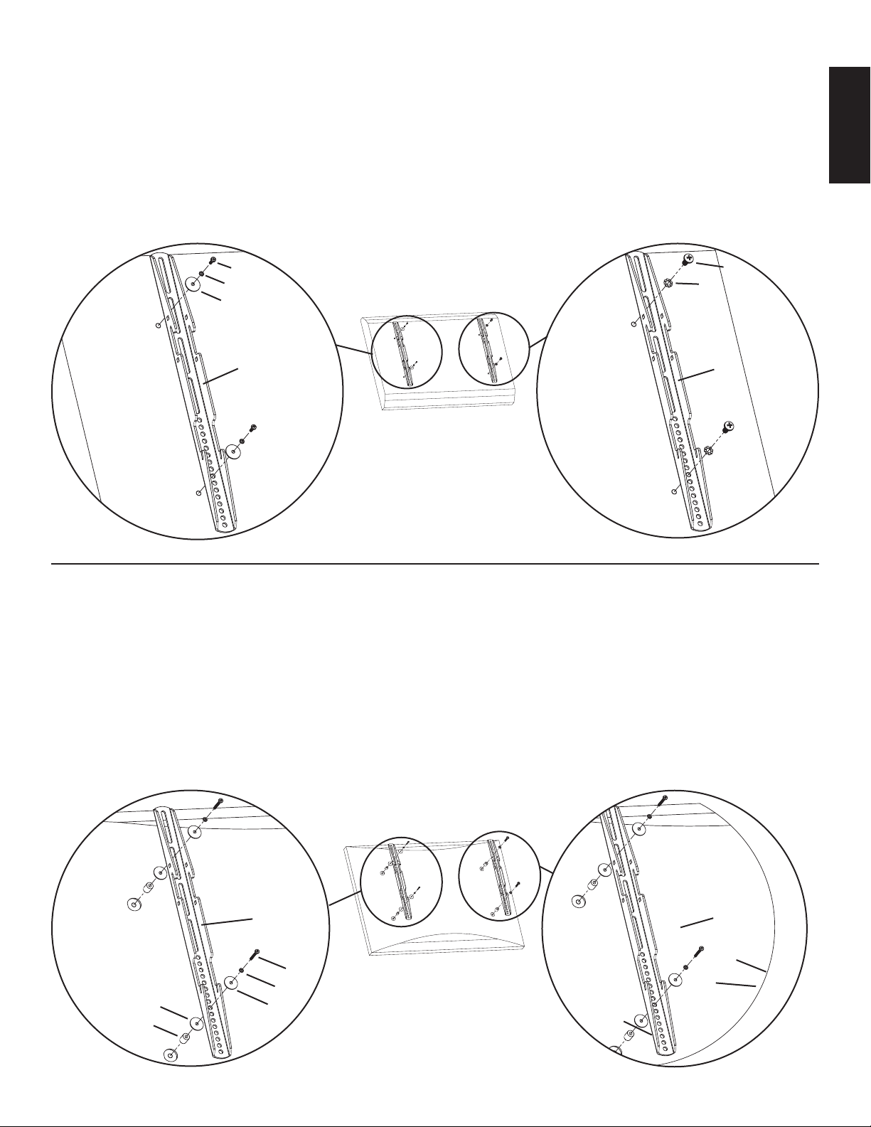
Step 4: Attaching the Monitor Brackets to a television with a curved back
WARNING: DO NOT LAY THE TELEVISION FACE DOWN ON THE GLASS, lean it up against a wall or other solid surface!
Laying the television down on the glass may cause permanent damage.
The Monitor Brackets (c) should be placed as vertically close to center of the television as possible before installation. If your TV has
a curved back and requires either a M4 or M5 diameter bolt, thread a M4 x 30 (f) or a M5 x 30 (h) Bolt through the appropriate Lock
Washer (m,n), an M4/M5 Washer (t), the Monitor Bracket, an M4/M5 Washer, a M4/M5 Spacer (q) and into the TV as seen in Detailed
View A of Diagram 4. If you determined that your TV requires a Bolt with a M6 or M8 Diameter, thread a M6 x 35 (j) or a M8 x 40 (l)
Bolt through the appropriate Lock Washer (o,p), the Monitor Bracket, a M6/M8 Spacer (r) and into the TV as seen in Detailed View B
of Diagram 4. Proceed to tighten the Bolts firmly with a phillips screw driver.
Detailed View A Detailed View B
Diagram 4
c c
f, h j,l
m,n o,p
t t
q r
Page 6

Step 5: Attaching the Monitor Brackets to a television with recessed threaded inserts.
WARNING: DO NOT LAY THE TELEVISION FACE DOWN ON THE GLASS, lean it up against a wall or other solid surface!
Laying the television down on the glass may cause permanent damage.
The Monitor Brackets (c) should be placed as vertically close to center of the television as possible before installation. If your TV has
threaded inserts that are recessed and requires either a M4 or M5 diameter bolt, thread a M4 x 30 (f) or a M5 x 30 (h) Bolt through the
appropriate Lock Washer (m,n), an M4/M5 Washer (t), the Monitor Bracket, an M4/M5 Washer, a M4/M5 Spacer (q) and into the TV as
ENGLISH
seen in Detailed View A of Diagram 5. If you determined that your TV requires a Bolt with a M6 or M8 Diameter, thread a M6 x 35 (j)
or a M8 x 40 (l) Bolt through the appropriate Lock Washer (o,p), the Monitor Bracket, a M6/M8 Spacer (r) and into the TV as seen in
Detailed View B of Diagram 5. Proceed to tighten the Bolts firmly with a phillips screw driver.
Detailed View A Detailed View B
Diagram 5
f,h j,l
t m,n r o,p
q t
Diagram 6 Detailed View
Step 6: Choose mounting position:
c
w d d x
You can mount your television in either of two positions:
flat or at a 5 degree downward tilt. To mount the television
flat to the wall use only the Monitor Brackets (c). To mount
the television in the 5 degree tilt position you must first add
two Gussets (d) to each Monitor Bracket with two Carriage
Bolts (w) and two Gusset Nuts (x) as shown in Diagram 6.
Step 7: Hang the TV onto the Wall Plate:
First hook the Monitor Brackets (c) over the top of the Wall Plate (a), then let the bottom of the Monitor Brackets rotate in under the
bottom of the Wall Plate. This process is shown with the flat mount option in Diagram 7a, and with the 5 degree tilt option in Diagram
7b. Once the TV is in place, insert the Safety Bar (b) into the slots in the bottom of the Monitor Brackets so that it sits behind the bottom
tab on the Wall Plate as shown in Diagram 7c. The bend should face toward the wall. Once the bar passes out the other side of the Wall
Plate a padlock can be added to the hole in the Safety Bar for additional security.
Diagram 7a Diagram 7b Diagram 7c
c
d
c
a a
a
slot for safety bar b
wall wall c
Page 7

L A U N I Ó N D E F O R M A Y F U N C I Ó N
Instrucciones de armado del soporte de pared VMPL2 para pantalla plana
Gracias por elegir el soporte de pared Vision Mount de Sanus Systems. Este producto ha sido diseñado para montar televisores con
pantalla plana con un peso de hasta 79,4 kg en una pared vertical. Este modelo le permite montar un televisor de pantalla plana contra la
pared a una inclinación fija de 5 grados.
Advertencia de seguridad: Si no entiende estas instrucciones o si tiene alguna duda con respecto a la seguridad de la instalación, llame a
un contratista calificado o llámenos al 800.359.5520 (en EE.UU.) o al 31 (0) 20 5708938 (en Europa). También nos puede visitar en nuestro
sitio www.sanus.com. Podemos ayudarle rápidamente a responder sus preguntas sobre la instalación o con respecto a las piezas faltantes o
defectuosas. Las piezas de repuesto para los productos Sanus comprados a través de un distribuidor autorizado se enviarán directamente a usted.
Revise cuidadosamente para asegurarse de que no hayan piezas faltantes ni defectuosas. Nunca usar piezas que presenten algún defecto. La
instalación incorrecta puede provocar daño o lesiones graves. No usar este producto para fines que no estén especificados explícitamente por
Sanus Systems. Sanus Systems no se hace responsable de los daños ni de las lesiones causadas por el montaje, armado o uso incorrectos.
Nota: La tornillería de montaje suministrada no es para paredes con pies derechos de acero ni para paredes con bloques de cemento. Si se tiene
alguna duda sobre la naturaleza de la pared, consultar con un contratista. Sanus ha hecho todo lo posible para asegurar que se incluya toda la
tornillería de montaje necesaria. Si la tornillería que se necesita no se incluye, consultar en una ferretería local o llamar a Sanus Systems.
Herramientas necesarias: Broca de 3/16 pulgadas, broca para concreto de 1/2 pulgada para instalaciones sobre ladrillo, concreto o
bloques de hormigón, juego de llaves mecánicas o casquillos, destornillador Phillips.
Piezas suministradas:
(1) Placa adaptadora - a (1) Barra de seguridad - b (2) Soporte de monitor - c (4) Suplemento
de refuerzo - d
ESPAÑOL
(4) Perno M4 x 12 - e (4) Perno M4 x 30 - f (4) Perno M5 x 12 - g (4) Perno M5 x 30 - h
(4) Perno M6 x 12 mm - i (4) Perno M6 x 35 - j (4) Perno M8 x 16 - k (4) Perno M8 x 40 - l
(4) Arandela de seguridad (4) Arandela de seguridad (4) Arandela de seguridad (4) Arandela de seguridad
M4 - m M5 - n M6 - o M8 - p
(4) Espaciador M4/M5 - q (4) Espaciador M6/M8 - r (6) Arandela de tirafondo - s (8) Arandela M4/M5 - t
(6) Tirafondo - u (6) Anclaje para concreto - v
(4) Perno de máquina - w (4) Tuerca de suplemento de refuerzo - x
Page 8

Paso 1: Montaje de la placa de pared: Se proporcionan opciones para montaje sobre pie derecho de madera, ladrillo, concreto sólido
y bloque de hormigón.
Montaje sobre pie derecho de madera:
La placa de pared (a) se debe montar sobre dos pies derechos separados al menos por 30,5 cm. Utilizar un detector de vigas de alta
calidad para localizar dos pies derechos adyacentes. Es una buena idea verificar la ubicación de los pies derechos con un punzón o clavo
delgado, como se ilustra en el diagrama 1a. Perforar con antelación un agujero profundo de 6,3 cm en la altura deseada de cada pie derecho
utilizando una broca de 3/16 pulgada. Asegurarse que estos agujeros queden en el centro de los pies derechos y nivelados entre ellos. Utilizar
la placa de pared como una plantilla para marcar la posición del segundo agujero en cada pie derecho. Perforar agujeros de 6,3 cm con una
broca de 3/16 pulgada en la ubicación marcada. Conectar la placa en la pared utilizando los cuatro tirafondos de 1/4 x 2,5 pulgadas (u) y las
cuatro arandelas de tirafondo (s). Asegurarse que la placa de pared quede orientada de manera que la superficie plana en el centro de la placa
quede contra la pared y que los tirafondos queden a cada lado de los dos agujeros grandes en el centro, como se ilustra en el diagrama 1b.
Montaje en ladrillo, concreto y bloque de hormigón:
Utilizar la placa de pared (a) como una plantilla para marcar las 6 posiciones de los agujeros en la pared. Los agujeros exteriores deben caer a
la izquierda o derecha de los dos agujeros grandes en el centro de la placa. Tres en la hilera superior de ranuras y tres más en la hilera inferior.
ESPAÑOL
Asegurarse de que estos agujeros estén nivelados y que haya una separación de al menos 15 cm entre ellos. Perforar cuidadosamente estos
agujeros con una broca para concreto de 1/2 pulgada a una profundidad mínima de 6,3 cm. Insertar un anclaje para concreto (v) en cada uno
de estos agujeros. Asegurarse de que el anclaje quede asentado completamente a ras con la superficie de concreto, incluso si hubiera una
capa de yeso o de otro material encima. Conectar la placa en la pared utilizando 6 tirafondos (u) y 6 arandelas de tirafondo (s).
Diagrama 1a Diagrama 1b
a
u s
Paso 2: Seleccionar la tornillería correcta para el televisor
¡Siempre asegurarse que el televisor esté desenchufado antes de pasar cualquier perno por el panel trasero!
Cuidadosamente enroscar los pernos a mano antes de apretarlos en el televisor. ¡Si siente alguna resistencia, retirar el perno
inmediatamente! Si no puede encontrar la tornillería correcta para su televisor, consultar en una ferretería local o llamar a
Sanus Systems.
Ubicar los insertos roscados en la parte trasera del televisor con pantalla plana, y determinar cuál de los pernos suministrados es el de diámetro
correcto. Para probar el diámetro, enroscar los pernos a mano en el televisor hasta encontrar el diámetro que encaje correctamente.
Luego, determinar el largo correcto del perno requerido. Los televisores con la parte trasera plana requerirán los pernos cortos sin un
espaciador. Algunos televisores tienen la parte trasera curvada o bien tienen insertos roscados. Esto puede requerir un perno más largo
junto con un espaciador que se debe colocar entre el televisor y el soporte de monitor.
Una vez que se tenga seleccionado el perno correcto, se pueden seguir los diagramas de más abajo para ver la tornillería adicional que
se necesitará para montar los soportes de monitor (c) en el televisor. Para un televisor con la parte trasera plana, ver el paso 3 para las
instrucciones de instalación. Para un televisor con la parte trasera curvada, ver el paso 4. Para un televisor que tenga la parte trasera con
insertos roscados, ver el paso 5.
Diagramas de tornillería:
M4 x 12
e f g h i j k l
M4 x 30
M5 x 12
M5 x 30
M6 x 12
M6 x 35
M8 x 16
M8 x 40
m m n n o o p p
t t t t r r
q q
t t
Page 9

Paso 3: Conexión de los soportes de monitor a un televisor con la parte trasera plana
ADVERTENCIA: ¡NO PONER EL TELEVISOR BOCA ABAJO SOBRE EL VIDRIO, hacerlo descansar contra la pared u otra
superficie sólida! Poner el televisor boca abajo podría dañarlo de forma permanente.
Los soportes de monitor (c) se deben poner lo más verticalmente posible al centro del televisor antes de la instalación. Para un televisor
con la parte trasera plana que requiera el perno de diámetro M4 ó M5, pasar un perno M4 x 12 (e) o M5 x 12 (g) por la arandela (m,n)
correspondiente, una arandela M4/M5 (t), el soporte de monitor y finalmente insertarlo en el televisor. Ver la vista detallada A del
diagrama 3 para más ayuda. Si el televisor requiere el perno de diámetro M6 ó M8 , pasar un perno M6 x 12 (i) ó M8 x 16 (k) por la
arandela de seguridad (o,p) correspondiente, por el soporte de monitor e insertarlo en el televisor. Ver la vista detallada B del diagrama 3
para más ayuda. Proceder a apretar firmemente los pernos con un destornillador phillips.
Vista detallada A Vista detallada B
e,g i,k
m,n Diagrama 3 o,p
t
c c
ESPAÑOL
Paso 4: Conexión de los soportes de monitor a un televisor con la parte trasera curvada
ADVERTENCIA: ¡NO PONER EL TELEVISOR BOCA ABAJO SOBRE EL VIDRIO, hacerlo descansar contra la pared u otra
superficie sólida! Poner el televisor boca abajo podría dañarlo de forma permanente.
Los soportes de monitor (c) se deben poner lo más verticalmente posible al centro del televisor antes de la instalación. Si el televisor tiene
la parte trasera curva y requiere un perno M4 ó M5, pasar un perno M4 x 30 (f) o M5 x 30 (h) por la arandela de seguridad correspondiente
(m,n), una arandela M4/M5 (t), el soporte de monitor, una arandela M4/M5, un espaciador M4/M5 (q) y finalmente el televisor, como se
ilustra en la vista detallada A del diagrama 4. Si se determina que el televisor requiere un perno con diámetro M6 ó M8, pasar un perno
M6 x 35 (j) o M8 x 40 (l) por la arandela de seguridad correspondiente (o,p), el soporte de monitor, un espaciador M6/M8 (r) y finalmente
el televisor, como se ilustra en la vista detallada B del diagrama 4. Proceder a apretar los pernos firmemente con un destornillador Phillips.
Vista detallada A Vista detallada B
Diagrama 4
c c
f, h j,l
m,n o,p
t t
q r
Page 10

Paso 5: Conexión de los soportes de monitor a un televisor con insertos roscados.
ADVERTENCIA: ¡NO PONER EL TELEVISOR BOCA ABAJO SOBRE EL VIDRIO, hacerlo descansar contra la pared u otra
superficie sólida! Poner el televisor boca abajo podría dañarlo de forma permanente.
Los soportes de monitor (c) se deben poner lo más verticalmente posible al centro del televisor antes de la instalación. Si el televisor tiene
insertos roscados y requiere un perno M4 ó M5, pasar un perno M4 x 30 (f) o M5 x 30 (h) por la arandela de seguridad correspondiente
(m,n), una arandela M4/M5 (t), el soporte de monitor, una arandela M4/M5, un espaciador M4/M5 (q) y finalmente el televisor, como se
ilustra en la vista detallada A del diagrama 5. Si se determina que el televisor requiere un perno con diámetro M6 ó M8, pasar un perno
M6 x 35 (j) o M8 x 40 (l) por la arandela de seguridad correspondiente (o,p), el soporte de monitor, un espaciador M6/M8 (r) y finalmente
el televisor, como se ilustra en la vista detallada B del diagrama 5. Proceder a apretar los pernos firmemente con un destornillador Phillips.
Vista detallada A Vista detallada B
ESPAÑOL
Diagrama 5
f,h j,l
t m,n r o,p
q t
Diagrama 6 Vista detallada
Paso 6: Elegir la posición de montaje:
c
El televisor se puede montar en cualquiera de estas dos posiciones:
w d d x
de forma plana contra la pared o con una inclinación de 5 grados.
Para montar el televisor de forma plana contra la pared utilizar
sólo los soportes de monitor (c). Para montar el televisor con una
inclinación de 5 grados, se debe agregar primero dos suplementos
de refuerzo (d) a cada soporte de monitor con dos pernos de
máquina (w) y dos tuercas (x), como se ilustra en el diagrama 6.
Paso 7: Colgar el televisor en la placa de pared:
Primero enganchar los soportes de monitor (c) en la parte superior de la placa de pared (a), luego dejar que la base de los soportes de
monitor giren debajo de la placa de pared. Este proceso se muestra con la opción de montaje plano en el diagrama 7a y con la opción de
montaje con inclinación de 5 grados en el diagrama 7b. Una vez que el televisor está instalado en su lugar, insertar la barra de seguridad
(b) en las ranuras de la parte inferior de los soportes de monitor, de manera que se asiente detrás de la pestaña inferior de la placa de
pared, como se ilustra en el diagrama 7c. El doblez debe quedar orientado hacia la pared. Una vez que la barra sobrepasa el otro lado de
la placa de pared, se puede agregar un candado en el agujero de la barra para mayor seguridad.
Diagrama 7a Diagrama 7b Diagrama 7c
c
d
c
a a
a
ranura para barra b
de seguridad
pared pared c
Page 11

D I E E I N H E I T V O N F O R M U N D F U N K T I O N
Montageanweisungen für die VisionMount™-VMPL2- Wandhalterung für Flachbildschirme
Wir freuen uns, dass Sie sich für eine Vision Mount-Wandhalterung von Sanus Systems entschieden haben. Das Produkt ist für die
Montage von Flachbildfernsehern mit einem Gewicht von maximal 79,4 kg an einer vertikalen Wand vorgesehen. Auf diese Weise kann
der Fernseher flach an der Wand oder mit einer festen Neigung von 5 ° montiert werden.
Sicherheitshinweis: Wenn Sie diese Anweisungen nicht verstehen oder Zweifel an der Sicherheit der Montage haben, rufen Sie einen Fachmann
an oder kontaktieren Sie Sanus Systems telefonisch unter +1-800-359-5520 (USA) oder +31-(0)20-570-8938 (Europa). Sie können sich auch
auf unserer Website www.sanus.com informieren. Wir helfen Ihnen bei Montagefragen sowie fehlenden oder beschädigten Teilen gern weiter.
Ersatzteile für bei autorisierten Fachhändlern gekaufte Sanus-Produkte werden direkt an Ihre Adresse versendet. Es dürfen keine Bauteile
fehlen oder defekt sein. Verwenden Sie niemals beschädigte Teile! Unsachgemäße Montage kann Schäden am Gerät und schwere Verletzungen
hervorrufen! Das Produkt nicht für andere als von Sanus Systems explizit genannte Zwecke verwenden. Sanus Systems haftet nicht für Schäden
oder Verletzungen, die durch unsachgemäße Montage, fehlerhaften Zusammenbau oder unsachgemäße Nutzung entstehen.
Hinweis:: Das mitgelieferte Montagezubehör eignet sich nicht für Trockenwände mit Stahlträgern oder Wände aus Hohlblocksteinen
Bei Zweifeln an der Bauweise Ihrer Wand wenden Sie sich an einen Experten. Sanus Systems bemüht sich stets sicherzustellen, dass
das erforderliche Montagezubehör im Lieferumfang enthalten ist. Wenn das erforderliche Zubehör nicht im Lieferumfang enthalten ist,
wenden Sie sich bitte an Ihren Fachhändler vor Ort oder an Sanus Systems.
Erforderliche Werkzeuge: Bohrer 3/16 Zoll, Steinbohrer 1/2 Zoll für Ziegel, Beton oder Betonsteine, Maulschlüssel- oder
Steckschlüsselsatz, Kreuzschlitzschraubendreher.
Mitgelieferte
Teile:
(1) Wandplatte – a (1) Sicherheitsleiste – b (2) Monitorklammer – c (4) Eckbleche – d
DEUTSCH
(4) Schraube M4 x 12 – e (4) Schraube M4 x 30 – f (4) Schraube M5 x 12 – g (4) Schraube M5 x 30 – h
(4) Schraube M6 x 12 – i (4) Schraube M6 x 35 – j (4) Schraube M8 x 16 – k (4) Schraube M8 x 40 – l
(4) Sicherungsscheibe M4 – m (4) Sicherungsscheibe M5 – n (4) Sicherungsscheibe M6 – o (4) Sicherungsscheibe M8 – p
(4) Distanzstück M4/M5 – q (4) Distanzstück M6/M8 – r (6) Holzschraubenunterlegscheibe – s (8) Unterlegscheibe M4/M5 – t
(6) Holzschraubenunterlegscheibe – u (6) Betondübel – v
(4) Schlittenschraube – w (4) Eckblechmutter - x
Page 12

Schritt 1: Montage der Wandplatte: Es wird Zubehör zur Montage an Holzbalkenträgern, Ziegelwänden, Massivbeton und Betonsteinen
mitgeliefert.
Montage an einem Holzbalkenträger:
Die Wandplatte (a) muss an zwei Holzbalkenträgern mit mindestens 30,5 cm Abstand montiert werden. Mit einem hochwertigen
Sensor zwei benachbarte Balkenträger suchen. Die Lage der Träger kann am besten mit einer Ahle oder einem dünnen Nagel wie in
Abbildung 1a überprüft werden. An der entsprechenden Position in jedem Balkenträger mit einem Bohrer (3/16 Zoll) ein Loch mit einer
Tiefe von 6,4 cm vorbohren. Diese Bohrungen müssen sich in der Mitte der Balkenträger befinden und in gleicher Höhe liegen. Die
Wandplatte als Schablone zur Markierung der zweiten Bohrung in jedem Balkenträger verwenden. An der Markierung mit einem Bohrer
(3/16 Zoll) Löcher mit einer Tiefe von 6,4 cm bohren. Die Wandplatte mit vier Holzschrauben (1/4 x 6,4 cm) (u) und vier Holzschrauben
unterlegscheiben (s) an der Wand montieren. Die Wandplatte muss so ausgerichtet sein, dass die flache Fläche in der Mitte der Platte zur
Wand zeigt und sich an jeder Seite der großen Bohrlöcher in der Plattenmitte ein Paar Holzschrauben befindet (siehe Abbildung 1b).
Montage bei Ziegelwänden, Massivbeton und Betonsteinen:
Die Wandplatte (a) als Vorlage verwenden, um die sechs Bohrungen an der Wand zu markieren. Die Außenbohrungen müssen rechts und
links von den beiden großen Bohrungen in der Mitte der Platte liegen. Drei Bohrungen in die obere Reihe der Schlitze bohren und drei
weitere in die untere Reihe. Die Bohrungen müssen aufeinander ausgerichtet und in einem Abstand von mindestens 15,2 cm angeordnet
sein. Die Bohrungen mit einem Steinbohrer 1/2 Zoll mindestens 6,4 cm tief vorbohren. In jede Bohrung einen Betondübel (v) einführen.
Der Betondübel muss richtig sitzen und bündig mit der Betonoberfläche abschließen, selbst wenn davor eine Trockenwand oder anderes
Material angeordnet ist. Die Wandplatte mit sechs Holzschrauben (u) und sechs Holzschraubenunterlegscheiben (s) an der Wand anbauen.
Abbildung 1a Abbildung 1b
DEUTSCH
a
u s
Schritt 2: Das richtige Zubehör für den Fernseher auswählen
Beim Eindrehen von Schrauben an der Rückseite immer darauf achten, dass der Netzstecker des Fernsehers gezogen ist!
Vor dem Festziehen die Schrauben am Fernseher vorsichtig mit der Hand eindrehen. Wenn ein Widerstand zu spüren ist,
die Schraube sofort entfernen! Fehlen die entsprechenden Befestigungselemente für den Fernseher, können Sie entsprechende
Zubehörteile im Fachhandel kaufen oder sich direkt an Sanus Systems wenden.
Die Aussparungen der Gewindeeinsätze an der Rückseite des Flachbildfernsehers suchen und prüfen, welche der mitgelieferten
Schrauben den richtigen Durchmesser besitzen. Zur Prüfung des Durchmessers die Schrauben vorsichtig mit der Hand in den Fernseher
eindrehen, bis der Durchmesser genau passt.
Danach die korrekte Länge der betreffenden Schraube ermitteln. Fernseher mit flacher Rückseite benötigen eine kürzere Schraube und
kein Distanzstück. Manche Fernseher haben eine gekrümmte Rückseite oder Aussparungen für Gewindeeinsätze. Diese Geräte erfordern
eine längere Schraube sowie ein Distanzstück zwischen dem Fernseher und der Monitorklammer.
Nach Auswahl der richtigen Schraube entsprechend den Abbildungen arbeiten. Die Abbildungen zeigen, welches weitere Zubehör zur
Montage der Monitorklammern (c) für den Fernseher benötigt werden. Für einen Fernseher mit flacher Rückseite gilt Schritt 3 der
Montageanweisungen. Bei einem Fernseher mit gekrümmter Rückseite Schritt 4 beachten. Bei einem Fernseher mit Aussparungen für
die Gewindeeinsätze Schritt 5 beachten.
Abbildungen der Montageelemente:
M4 x 12
e f g h i j k l
M4 x 30
M5 x 12
M5 x 30
M6 x 12
M6 x 35
M8 x 16
M8 x 40
m m n n o o p p
t t t t r r
q q
t t
Page 13

Schritt 3: Monitorklammern an einem Fernseher mit flacher Rückseite befestigen.
VORSICHT: DEN FERNSEHER NICHT AUF DER GLASSTIRNFLÄCHE ABLEGEN, sondern gegen die Wand oder eine
andere feste Oberfläche lehnen! Wird der Fernseher auf dem Glas abgelegt, kann er dauerhaft beschädigt werden.
Die Monitorklammern (c) sollten möglichst genau vertikal zur Mitte des Fernsehers platziert werden, bevor die Montage beginnt. Bei
einem Fernseher mit flacher Rückseite, der eine Schraube M4 oder M5 benötigt, eine Schraube M4 x 12 (e) oder M5 x 12 (g) durch
die entsprechende Sicherungsscheibe (m, n), eine Unterlegscheibe M4/M5 (t), die Monitorklammer und schließlich in den Fernseher
eindrehen. Siehe Detailansicht A in Abbildung 3. Werden für den Fernseher Schrauben M6 oder M8 benötigt, eine Schraube M6 x 12 (i)
oder M8 x 16 (k) durch die entsprechende Sicherungsscheibe (o, p) und die Monitorklammer in den Fernseher eindrehen. Siehe dazu
Detailansicht B in Abbildung 3. Die Schrauben mit einem Kreuzschlitzschraubendreher gründlich festziehen.
Detailansicht A Detailansicht B
e, g i, k
m, n Abbildung 3 o, p
t
c c
DEUTSCH
Schritt 4: Montage der Monitorklammern an einem Fernseher mit gekrümmter Rückseite
VORSICHT: DEN FERNSEHER NICHT AUF DER GLASSTIRNFLÄCHE ABLEGEN, sondern gegen die Wand oder eine
andere feste Oberfläche lehnen! Wird der Fernseher auf dem Glas abgelegt, kann er dauerhaft beschädigt werden.
Die Monitorklammern (c) sollten möglichst genau vertikal zur Mitte des Fernsehers platziert werden, bevor die Montage beginnt.
Besitzt der Fernseher eine gekrümmte Rückseite und benötigt er entweder eine Schraube M4 oder M5, eine Schraube M4 x 30 (f) oder
M5 x 30 (h) durch die entsprechende Sicherungsscheibe (m, n), eine Unterlegscheibe M4/M5 (t), die Monitorklammer, eine Unterlegscheibe
M4/M5 und ein Distanzstück M4/M5 (q) stecken und in den Fernseher wie in Detailansicht A von Abbildung 4 eindrehen. Ist für den
Fernseher eine Schraube M6 oder M8 erforderlich, eine Schraube M6 x 35 (j) oder M8 x 40 (l) durch die entsprechende Sicherungsscheibe
(o,p), die Monitorklammer und das Distanzstück M6/M8 (r) in den Fernseher wie in Detailansicht B von Abbildung 4 eindrehen. Die
Schrauben mit einem Kreuzschlitzschraubendreherfest anziehen.
Detailansicht A Detailansicht B
Abbildung 4
c c
f, h j,l
m, n o, p
t t
q r
Page 14

Schritt 5: Anbau der Monitorklammern an einem Fernseher mit Aussparungen für Gewindeeinsätze
VORSICHT: DEN FERNSEHER NICHT AUF DER GLASSTIRNFLÄCHE ABLEGEN, sondern gegen die Wand oder eine
andere feste Oberfläche lehnen! Wird der Fernseher auf dem Glas abgelegt, kann er dauerhaft beschädigt werden.
Die Monitorklammern (c) sollten möglichst genau vertikal zur Mitte des Fernsehers platziert werden, bevor die Montage beginnt.
Besitzt der Fernseher Aussparungen für Gewindeeinsätze und benötigt er entweder eine Schraube M4 oder M5, eine Schraube
M4 x 30 (f) oder M5 x 30 (h) durch die entsprechende Sicherungsscheibe (m, n), die Unterlegscheibe M4/M5 (t), die Monitorklammer,
eine Unterlegscheibe M4/M5 und ein Distanzstück M4/M5 (q) stecken und in den Fernseher wie in Detailansicht A von Abbildung 5
eindrehen. Ist für den Fernseher eine Schraube M6 oder M8 erforderlich, eine Schraube M6 x 35 (j) oder M8 x 40 (l) durch die
entsprechende Sicherungsscheibe (o, p ), die Monitorklammer und das Distanzstück M6/M8 (r) in den Fernseher wie in Detailansicht B
von Abbildung 5 eindrehen. Die Schrauben mit einem Kreuzschlitzschraubendreher fest anziehen.
Detailansicht A Detailansicht B
Abbildung 5
f,h j,l
DEUTSCH
t m, n r o, p
q t
Abbildung 6 Detailansicht
Schritt 6: Die Montageposition auswählen:
c
Der Fernseher kann in zwei Positionen montiert werden:
w d d x
entweder flach an der Wand oder mit einer Neigung von 5 ° nach
unten. Zur Montage des Fernsehers flach an der Wand nur die
Monitorhalterungen (c) verwenden. Zur Montage des Fernsehers
mit einer Neigung von 5 ° zunächst die beiden Eckbleche (d) an
der jeweiligen Monitorklammer mit Schlittenschrauben (w) und
2 Muttern (x) wie in Abbildung 6 montieren.
Schritt 7: Anhängen des Fernsehers an die Wandplatte:
Zunächst die Monitorklammern (c) an der Oberseite der Wandplatte (a) auflegen, dann die Unterseite der Monitorklammern unter der
Wandplatte eindrehen. Die Schritte für einen Fernseher, der flach an der Wand montiert wird, werden in Abbildung 7a dargestellt, für
einen Fernseher, der mit 5 ° Neigung montiert wird, in Abbildung 7b. Die Sicherheitsleiste (b) so in die Schlitze an der Unterseite der
Monitorklammern einführen, dass sie wie in Abbildung 7c hinter der unteren Nase der Wandplatte sitzt. Die gebogene Seite muss zur
Wand zeigen. Wenn die Sicherheitsleiste an der anderen Seite der Wandplatte hervorsteht, kann ein Vorhängeschloss in dem Loch in der
Sicherheitsleiste montiert werden, um den Fernseher zusätzlich zu sichern.
Abbildung 7a Abbildung 7b Abbildung 7c:
c
d
c
a a
a
Schlitz für b
Sicherheitsschiene
Wand Wand c
Page 15

L’ U N I O N D E L A F O R M E E T D E L A F O N C T I O N
Instructions de montage du montant mural VMPL2 pour téléviseur à écran plat
Nous vous remercions d’avoir choisi un montant mural Vision Mount de Sanus Systems. Ce produit est conçu pour soutenir au mur des
téléviseurs à écran plat d’un poids maximal de 79,4 kg. Il vous permet d’installer le téléviseur à plat contre un mur ou incliné à 5 degrés.
Précautions de sécurité : Si vous ne comprenez pas ces instructions ou si vous avez un doute quant à la sécurité de cette installation, veuillez
faire appel à un technicien qualifié ou communiquez avec Sanus en composant le 1-800-359-5520 (aux É.-U.), ou le 31 (0) 20 5708938
(pour l’Europe). Vous pouvez aussi aller sur notre site Web au www.sanus.com. Les représentants de notre service à la clientèle peuvent
répondre rapidement à toute question concernant l’installation ou les pièces manquantes. Les pièces de rechange de produits Sanus
achetés auprès de distributeurs agréés vous seront livrées directement. Vérifiez soigneusement qu’il n’y a aucune pièce manquante
ou défectueuse. N’utilisez jamais de pièces défectueuses. Une installation incorrecte peut entraîner des dommages ou des blessures
graves. Ce produit ne doit être utilisé que pour des usages explicitement spécifiés par Sanus Systems. Sanus Systems ne pourra être tenu
responsable de dommages ou de blessures dus à un montage incorrect, à un assemblage incorrect ou à un usage incorrect.
Remarque : Le matériel de montage mural fourni n’est pas adapté aux cloisons à charpente d’acier ni aux anciennes cloisons en blocs
de cendre. Si vous n’êtes pas certain de la nature de votre cloison, veuillez consulter un entrepreneur. Sanus prend soin d’inclure toute la
visserie nécessaire au montage d’un téléviseur. Si toutefois la visserie dont vous avez besoin n’est pas incluse, consultez une quincaillerie
locale ou contactez directement Sanus Systems.
Outils requis : Mèche de 3/16 pouce, mèche à maçonnerie de 1/2 pouce permettant de percer les surfaces en béton de brique ou blocs
en béton, jeu de clés à douille ou jeu de douilles, tournevis cruciforme.
Pièces fournies :
(1) plaque murale - a (1) barre de sécurité - b (2) support du moniteur - c (4) gousset - d
FRANÇAIS
(4) boulon M4 x 12 - e (4) boulon M4 x 30 - f (4) boulon M5 x 12 - g (4) boulon M5 x 30 - h
(4) boulon M6 x 12 - i (4) boulon M6 x 35 - j (4) boulon M8 x 16 - k (4) boulon M8 x 40 - l
(4) rondelle-frein M4 - m (4) rondelle-frein M5 - n (4) rondelle-frein M6 - o (4) rondelle-frein M8 - p
(4) entretoise M4/M5 - q (4) entretoise M6/M8 - r (6) rondelle pour tire-fond - s (8) rondelle M4/M5 - t
(6) tire-fond - u (6) boulon d’ancrage pour béton - v
(4) boulon de carrosserie - w (4) écrou de gousset - x
Page 16

Étape 1 : Montage de la plaque murale Les options de montage sont les suivantes : ossature de bois, brique, béton monolithe et bloc de béton.
Montage sur ossature de bois :
La plaque murale (a) doit être fixée à deux montants de cloison distants d’au moins 30,5 cm. Servez-vous d’un détecteur de montants de
haute qualité pour repérer deux montants adjacents. Il est préférable de vérifier l’emplacement des montants à l’aide d’un poinçon ou d’un clou
mince tel qu’indiqué au schéma 1a. Percez au préalable un trou de 6,4 cm de profondeur à la hauteur souhaitée sur chaque montant à l’aide d’une
mèche de 3/16 pouce. Assurez-vous que ces trous sont bien centrés sur les montants et au même niveau l’un de l’autre. Servez-vous de la plaque
murale comme modèle pour marquer l’emplacement du second trou sur chaque montant. Percez des trous de 6,4 cm de profondeur à l’aide d’une
mèche de 3/16 pouce sur la marque de l’emplacement. Fixez la plaque murale sur le mur à l’aide des quatre tire-fonds 1/4 x 2,5 pouce (u) et des
quatre rondelles pour tire-fond (s). Assurez-vous que la plaque murale est orientée de façon à ce que la surface plane au centre de la plaque soit
contre le mur et que les tire-fonds se trouvent de chaque côté des deux grands trous au centre tel qu’indiqué sur le schéma 1b.
Montage sur brique, béton monolithe et bloc de béton :
Servez-vous de la plaque murale (a) comme modèle pour marquer 6 emplacements de trous sur le mur. Les trous extérieurs doivent tomber sur
la droite et sur la gauche des deux grands trous au milieu de la plaque. Trois sur la rangée supérieure des fentes et les trois autres sur la rangée
inférieure. Assurez-vous que ces trous sont au même niveau et que la distance entre chaque trou est d’au moins 15,2 cm. Prépercez ces trous à
l’aide d’une mèche de maçonnerie de 1/2 pouce à une profondeur minimale de 6,4 cm. Insérez un boulon d’ancrage pour béton (v) dans chacun
de ces trous. Assurez-vous que la cheville est complètement enfoncée dans la surface du béton même si elle est recouverte d’une couche de
cloison sèche ou de tout autre matériau. Fixez la plaque murale sur le mur à l’aide des 6 tire-fonds (u) et des 6 rondelles pour tire-fond (s).
Schéma 1a Schéma 1b
a
u s
FRANÇAIS
Étape 2 : Sélection de la visserie appropriée à votre téléviseur
Assurez-vous que le téléviseur est débranché avant de visser des boulons sur le panneau arrière !
Vissez avec précaution les boulons à la main et dans votre téléviseur avant de les serrer définitivement. Si vous ressentez une
résistance quelconque, enlevez le boulont immédiatement! Si vous ne trouvez pas la visserie appropriée à votre téléviseur,
consultez une quincaillerie locale ou contactez directement Sanus Systems.
Repérez les inserts filetés sur le panneau arrière du téléviseur à écran plat et déterminez parmi les boulons ceux qui ont le diamètre approprié. Pour
tester tous les diamètres, serrez avec précaution les boulons à la main dans votre téléviseur jusqu’à ce que vous trouviez le diamètre convenable.
Déterminez ensuite la longueur de boulon appropriée. Les téléviseurs à panneau arrière plat requièrent l’utilisation de boulons plus
courts sans entretoise. Le panneau arrière de certains téléviseurs est courbé ou doté d’inserts filetés renfoncés. Utilisez un boulon plus
long en plaçant une entretoise entre le téléviseur et le support du moniteur.
Après avoir choisi le boulon approprié, vous pouvez suivre les schémas ci-dessous afin de déterminer la visserie additionnelle nécessaire au
montage des supports du moniteur (c) sur votre téléviseur. Pour un téléviseur à panneau arrière plat, voir les instructions d’installation à l’étape 3.
Pour un téléviseur à panneau arrière courbé, voir l’étape 4. Pour un téléviseur à panneau arrière doté d’inserts filetés renfoncés, voir l’étape 5.
Schémas du matériel :
M4 x 12
e f g h i j k l
M4 x 30
M5 x 12
M5 x 30
M6 x 12
M6 x 35
M8 x 16
M8 x 40
m m n n o o p p
t t t t r r
q q
t t
Page 17

Étape 3 : Fixation des supports du moniteur sur un téléviseur à panneau arrière plat
AVERTISSEMENT : NE PAS POSER LE TÉLÉVISEUR SUR L’ÉCRAN DE VERRE. L’appuyer contre un mur ou sur une
surface solide ! Un téléviseur posé sur l’écran de verre risque de subir des dommages permanents.
Placez les supports du moniteur (c) verticalement aussi près que possible du centre du téléviseur avant l’installation. Pour un téléviseur
à panneau arrière plat qui nécessite l’utilisation d’un boulon de diamètre M4 ou M5, faites passer un boulon M4 x 12 (e) ou M5 x 12 (g)
dans la rondelle de blocage appropriée (m, n), puis dans une rondelle M4/M5 (t), et dans le support du moniteur et faites ensuite passer
le tout dans le téléviseur. Reportez-vous à la vue détaillée A du schéma 3 si vous avez besoin d’aide. Si votre téléviseur nécessite un
boulon de diamètre M6 ou M8, faites passer un boulon M6 x 12 (i) ou M8 x 16 (k) dans la rondelle de blocage (o, p) appropriée, puis
dans le support du moniteur et finalement dans le téléviseur. Reportez-vous à la vue détaillée B du schéma 3 si vous avez besoin d’aide.
Resserrez bien ensuite les boulons à l’aide d’un tournevis cruciforme.
Vue détaillée A Vue détaillée B
e, g i, k
m, n Schéma 3 o, p
t
c c
FRANÇAIS
Étape 4 : Fixation des supports du moniteur sur un téléviseur à panneau arrière courbé
AVERTISSEMENT : NE PAS POSER LE TÉLÉVISEUR SUR L’ÉCRAN DE VERRE. L’appuyer contre un mur ou sur une
surface solide ! Un téléviseur posé sur l’écran de verre risque de subir des dommages permanents.
Placez les supports du moniteur (c) verticalement aussi près que possible du centre du téléviseur avant l’installation. Si le téléviseur à
panneau arrière courbé requiert l’utilisation d’un boulon M4 ou M5, faites passer un boulon M4 x 30 (f) ou M5 x 30 (h) par la rondelle de
blocage appropriée (m, n), une rondelle M4/M5 (t), le support du moniteur, une rondelle M4/M5, une entretoise M4/M5 (q) et vissez-le dans
le téléviseur tel qu’illustré sur la vue détaillée du schéma 4. Si votre téléviseur requiert l’utilisation d’un boulon M6 ou M8, faites passer un
boulon M6 x 35 (j) ou M8 x 40 (l) par la rondelle de blocage appropriée (o, p), le support du moniteur, une entretoise M6/M8 (r) et vissez-le
dans le téléviseur tel qu’illustré sur la vue détaillée B du schéma 4. Serrez bien ensuite les boulons à l’aide d’un tournevis cruciforme.
Vuedétaillée A Vue détaillée B
Schéma 4
c c
f, h j, l
m, n o, p
t t
q r
Page 18

Étape 5 : Fixation des supports du moniteur sur un téléviseur à inserts filetés renfoncés.
AVERTISSEMENT : NE PAS POSER LE TÉLÉVISEUR SUR L’ÉCRAN DE VERRE. L’appuyer contre un mur ou sur une
surface solide ! Un téléviseur posé sur l’écran de verre risque de subir des dommages permanents.
Placez les supports du moniteur (c) verticalement aussi près que possible du centre du téléviseur avant l’installation. Si votre téléviseur a des
inserts filetés renfoncés qui requièrent l’utilisation d’un boulon M4 ou M5, faites passer un boulon M4 x 30 (f) ou M5 x 30 (h) par la rondelle
de blocage appropriée (m, n), la rondelle M4/M5 (t), le support du moniteur, une rondelle M4/M5, l’entretoise M4/M5 (q) et vissez-le dans
le téléviseur tel qu’illustré sur la vue détaillée du schéma 5. Si votre téléviseur requiert l’utilisation d’un boulon M6 ou M8, faites passer un
boulon M6 x 35 (j) ou un M8 x 40 (l) par la rondelle de blocage appropriée (o, p), le support du moniteur, l’entretoise M6/M8 (r) et vissez-le
dans le téléviseur tel qu’illustré sur la vue détaillée B du schéma 5. Serrez bien ensuite les boulons à l’aide d’un tournevis cruciforme.
Vue détaillée A Vue détaillée B
Schéma 5
f, h j, l
t m, n r o, p
q t
Schéma 6 Vue détaillée
Étape 6 : Sélection de la position de montage :
c
Vous pouvez installer votre téléviseur dans l’une des
w d d x
deux positions : à plat ou incliné vers le bas à 5 degrés.
FRANÇAIS
Pour installer le téléviseur à plat contre le mur, utilisez
uniquement les supports du moniteur (c). Pour installer le
téléviseur incliné à 5 degrés, vous devez d’abord ajouter
deux goussets (d) sur chaque support du moniteur avec les
deux boulons mécaniques (w) et les deux écrous de gousset
(x) tel qu’indiqué sur le schéma 6.6.
Étape 7 : Suspension du téléviseur sur la plaque murale :
Accrochez d’abord les supports du moniteur (c) au-dessus de la plaque murale (a), puis laissez le bas des supports du moniteur pivoter
sous le bas de la plaque murale. L’installation est illustrée avec l’option de montage à plat sur le schéma 7a et avec l’option d’inclinaison
à 5 degrés sur le schéma 7b. Une fois le téléviseur en place, insérez la barre de sécurité (b) dans les fentes au bas des supports du moniteur
pour qu’elle s’appuie à l’arrière de la patte inférieure sur la plaque murale tel qu’indiqué sur le schéma 7c. La courbe doit être dirigée
vers le mur. Une fois que la barre ressort de l’autre côté de la plaque murale, vous pouvez ajouter un cadenas dans le trou de la barre de
sécurité pour sécuriser l’installation.
Schéma 7a Schéma 7b Schéma 7c
c
d
c
a a
a
fente pour la barre b
de sécurité
mur mur c
Page 19

L ' U N I O N E D I F O R M A E F U N Z I O N E
Istruzioni per il montaggio della staffa per parete VMPL2 per pannelli piatti
Grazie per aver scelto un sistema di montaggio per parete Sanus Systems Vision Mount. Questo prodotto è progettato per montare
televisori a pannello piatto che pesano fino a 80 kg su una parete verticale. Ciò consente di montare il televisore piatto sul muro o a
un’inclinazione fissa di 5 gradi.
Avvertenza sulla sicurezza: se non si comprendono queste istruzioni o si hanno dubbi sulla sicurezza dell’installazione, rivolgersi a un
installatore specializzato o contattare la Sanus al numero verde USA 800.359.5520 o, in Europa, al numero +31 (0) 20 5708938. È anche
possibile visitare il nostro sito Web all’indirizzo www.sanus.com. Il nostro servizio di assistenza clienti potrà rispondere rapidamente
alle domande relative all’installazione o alle parti mancanti o danneggiate. Le parti di ricambio per i prodotti Sanus acquistati attraverso
i rivenditori autorizzati verranno spedite direttamente al cliente. Controllare attentamente che non vi siano parti mancanti o difettose.
Non utilizzare parti difettose. L’installazione errata può causare danni o lesioni gravi. Non utilizzare questo prodotto per scopi diversi
da quelli specificamente indicati dalla Sanus Systems. La Sanus Systems non è responsabile di danni o lesioni causati da montaggio o
utilizzo non corretti.
Nota: la minuteria metallica fornita per il montaggio a parete non è per pareti metalliche o vecchie pareti di blocchi di calcestruzzo.
Se non si è sicuri della natura della parete, consultare un rappresentante locale. La Sanus fa ogni sforzo possibile per assicurare che sia
inclusa tutta la minuteria metallica necessaria per il televisore. Se la minuteria metallica non è inclusa, consultare il ferramenta locale o
chiamare la Sanus Systems.
Strumenti necessari: punta per trapano da 3/16 pollici, punta per muratura da 1/2 pollice per mattoni in cemento o installazioni con
blocchi in cemento, chiavi o chiavi a testa esagonale, cacciavite Phillips.
Parti fornite:
(4) tassello di
(1) piastra per parete - a (1) barra di sicurezza - b (2) staffa per monitor - c ancoraggio - d
ITALIANO
(4) bullone M4 x 12 – e (4) bullone M4 x 30 - f (4) bullone M5 x 12 - g (4) bullone M5 x 30 - h
(4) bullone M6 x 12 - i (4) bullone M6 x 35 - j (4) bullone M8 x 16 - k (4) bullone M8 x 40 - l
(4) controrondella M4 - m (4) controrondella M5 - n (4) controrondella M6 - o (4) controrondella M8 - p
(4) distanziale M4/M5 - q (4) distanziale M6/M8 - r (6) rondella per tirafondo - s (8) rondella M4/M5 - t
(6) tirafondo - u (6) ancora per cemento - v
(4) bullone di trasporto - w (4) dado per tassello di ancoraggio - x
Page 20

Fase 1: montare la piastra a parete: Sono disponibili le opzioni di montaggio per travi in legno, mattoni, calcestruzzo e blocchi di
cemento.
Montaggio su travi di legno:
La piastra a parete (a) deve essere montata su due perni di legno distanti almeno 30 cm. Usare un rilevatore di travi in legno di alta qualità
per individuare due travi in legno adiacenti. È una buona idea verificare la posizione delle travi in legno con un punteruolo o con un chiodo
sottile come indicato in Figura 1a. Forare preventivamente un foro ad una profondità di 6,4 cm alla quota desiderata di ogni trave di legno usando
una punta per trapano da 3/16 pollice. Assicurarsi che questi fori vengano praticati nell’area centrale delle travi e allo stesso livello fra loro.
Utilizzare la piastra a parete come maschera per contrassegnare la posizione in ogni trave. Effettuare i fori a una profondità di 6,4 cm usando
una punta per trapano da 3/16 pollice nella posizione contrassegnata. Collegare la piastra per parete alla parete usando i quattro tirafondi da 1/4
per 2,5 pollici (u) e le due rondelle per tirafondo (s). Assicurarsi che la piastra per parete sia orientata in modo che la superficie piatta al
della piastra sia contro la parete e che una serie di tirafondi si trovi su ogni lato dei due grandi fori al centro come mostrato nella Figura 1b.
Montaggio per mattone, cemento solido e blocco di cemento:
Utilizzare la piastra a parete (a) come maschera per contrassegnare 6 posizioni per fori sulla parete. I fori esterni devono trovarsi a sinistra
e a destra dei due grandi fori al centro della piastra. Tre nella fila superiore degli alloggiamenti e altri tre nella fila inferiore. Assicurarsi
che questi fori siano a livello e vi siano almeno 15 cm tra ogni due fori. Effettuare con cura un foro preliminare ad una profondità di
almeno 6,4 cm usando una punta per 1/2 pollice. Inserire un’ancora per cemento (v) in ognuno di questi fori. Assicurarsi che l’ancora
sia sistemata completamente a livello con la superficie di cemento anche se vi è uno strato di stucco o altro materiale davanti. Collegare
la piastra per parete alla parete usando i 6 tirafondi (u) e le 6 rondelle per tirafondi (s).
Figura 1a Figura 1b
centro
a
u s
Fase 2: selezionare la minuteria metallica appropriata per il televisore
Assicurarsi sempre che il televisore sia scollegato dall’alimentazione prima di inserire i bulloni sul pannello posteriore.
Avvitare i bulloni con cura e a mano nel televisore di serrarli. Se si avverte resistenza, rimuovere immediatamente il bullone. Se non
ITALIANO
si trovano le parti di ferramenta appropriate per il televisore, rivolgersi a un ferramenta locale o chiamare la Sanus Systems.
Individuare gli inserti filettati sul retro del televisore piatto e stabilire quale dei bulloni forniti è del diametro corretto. Per testare ogni
diametro, inserire i bulloni attentamente nel televisore a mano fino a trovare il diametro che si adatta in modo corretto.
Quindi, determinare la lunghezza corretta del bullone richiesto. I televisori con retro piatto richiedono uno dei bulloni più corti e nessun
distanziale. Alcuni televisori sul retro presentano una curva o degli inserti filettati incassati. Ciò può richiedere un bullone più lungo
insieme a un distanziale tra il televisore e la staffa per monitor.
Una volta selezionato il bullone corretto, è possibile seguire le figure che seguono per vedere quale altra minuteria metallica è necessario
per montare le staffe del monitor (c) sul televisore. Per un televisore con retro piatto, vedere la Fase 3 per le istruzioni di installazione. Per
un televisore con retro curvo, vedere la Fase 4. Per un televisore che presenta sul retro degli inserti filettati incassati vedere la Fase 5.
Schemi per la minuteria:
M4 x 12
e f g h i j k l
M4 x 30
M5 x 12
M5 x 30
M6 x 12
M6 x 35
M8 x 16
M8 x 40
m m n n o o p p
t t t t r r
q q
t t
Page 21

Fase 3: collegare le staffe del monitor sui televisori con un retro piatto
AVVERTENZA: NON APPOGGIARE IL TELEVISORE RIVOLTO VERSO IL BASSO SUL VETRO: appoggiarlo invece a
una parete o su un’altra superficie dura! Se il televisore viene appoggiato sul vetro possono verificarsi dei danni permanenti.
Le staffe per monitor (c) devono essere posizionate quanto più vicine al centro verticale del televisore prima dell’installazione. Per
televisori con retro piatto che necessitano di un bullone di diametro M4 o M5, avvitare un bullone M4 x 12 (e) o M5 x 12 (g) attraverso
la controrondella appropriata (m, n), una rondella M4/M5 (t), la staffa del me infine nel televisore. Vedere la vista dettagliata A della
Figura 3 per assistenza. Se il Televisore necessita di un bullone M6 o M8 avvitare un bullone M6 x 12 (i) o a M8 x 16 (k) attraverso
la controrondella appropriata (o, p), attraverso la staffa per monitor e nel televisore. Vedere la vista dettagliata B della Figura 3 per
assistenza. Procedere serrando i bulloni in modo sicuro con un cacciavite Phillips.
Vista dettagliata A Vista dettagliata B
e,g i,k
m,n Figura 3 o,p
t
c c
Fase 4: collegare le staffe del monitor sul televisore con un retro curvo
AVVERTENZA: NON APPOGGIARE IL TELEVISORE RIVOLTO VERSO IL BASSO SUL VETRO: appoggiarlo invece a
una parete o su un’altra superficie dura! Se il televisore viene appoggiato sul vetro possono verificarsi dei danni permanenti.
Le staffe per monitor (c) devono essere posizionate quanto più vicine al centro verticale del televisore prima dell’installazione. Se il
televisore ha il retro curvo e necessita di un bullone del diametro M4 o M5, avvitare un bullone M4 x 30 (f) o M5 x 30 (h) attraverso
la controrondella appropriata (m,n), una rondella M4/M5 (t), la staffa del monitor, una rondella M4/M5, un distanziale M4/M5 (q) e
nel televisore come indicato nella vista dettagliata A della Figura 4. Se il televisore necessita un bullone M6 o M8, avvitare un bullone
M6 x 35 (j) o M8 x 40 (l) attraverso la controrondella appropriata (o,p), attraverso la staffa per Monitor, un distanziale M6/M8 (r) e nel
televisore come indicato nella vista dettagliata B della Figura 4. Serrare bene i bullonicon un cacciavite Phillips.
Vista dettagliata A Vista dettagliata B
Figura 4
c c
f, h j,l
m,n o,p
t t
q r
ITALIANO
Page 22

Fase 5: collegare le staffe del monitor al televisore con inserti filettati con recesso.
AVVERTENZA: NON APPOGGIARE IL TELEVISORE RIVOLTO VERSO IL BASSO SUL VETRO: appoggiarlo invece a
una parete o su un’altra superficie dura! Se il televisore viene appoggiato sul vetro possono verificarsi dei danni permanenti.
Le staffe per monitor (c) devono essere posizionate quanto più vicine al centro verticale del televisore prima dell’installazione. Se il
televisore ha inserti filettati con recesso e necessita di un bullone del diametro M4 o M5, avvitare un bullone M4 x 30 (f) o M5 x 30 (h)
attraverso la controrondella appropriata (m,n), una rondella M4/M5 (t), la staffa del monitor, una rondella M4/M5, un distanziale M4/M5
(q) e nel televisore come indicato nella vista dettagliata A della Figura 5. Se il televisore necessita di un bullone M6 o M8, avvitare un
bullone M6 x 35 (j) o M8 x 40 (l) attraverso la rondella opportuna (o,p), la staffa per monitor, un distanziale M6/M8 (r) e nel televisore
come illustrato nella vista dettagliata B della figura 5. Serrare a fondo i bulloni con un cacciavite Phillips.
Vista dettagliata A Vista dettagliata B
Figura 5
f,h j,l
t m,n r o,p
q t
Figura 6 Vista dettagliata
Fase 6: scegliere laposizione per il montaggio:
c
Il televisore può essere montato in due posizioni: piatto o
w d d x
inclinato di 5 gradi verso il basso. Per montare il televisore
piatto sulla parete usare solo le staffe per monitor (c). Per
montare il televisore in una posizione inclinata di 5 gradi, è
necessario aggiungere due tasselli di ancoraggio (d) su ogni
staffa per monitor con due bulloni di trasporto (w) e due dadi
per tasselli di ancoraggio (x) come mostrato nella Figura 6.
ITALIANO
Fase 7: appendere il televisore sulla piastra per parete:
Innanzitutto agganciare le staffe per monitor (c) sulla parte superiore della piastra per parete (a), quindi consentire alla parte inferiore
delle staffe per monitor di ruotare verso l’interno sotto la parte inferiore della staffa per parete. Questo processo viene mostrato con
un’opzione del montaggio piatto nella Figura 7a e con un’opzione per l’inclinazione di 5 gradi nella Figura 7b. Una volta che il televisore
è in posizione, inserire la barra di sicurezza (b) negli alloggiamenti nella parte inferiore delle staffe per monitor in modo che si trovi dietro
la linguetta inferiore sulla piastra per parete nella Figura 7c. La banda deve essere rivolta verso la parete. Una volta che la barra passi
dall’altro lato della piastra per parete, è possibile aggiungere un lucchetto al foro nella barra di sicurezza per sicurezza aggiuntiva.
Figura 7a Figura 7b Figgura 7c
c
d
c
a a
a
alloggiamento per b
barra di sicurezza
parete parete c
Page 23

Инструкция по сборке настенного крепления для плоскопанельных телевизоров VMPL2
Благодарим Вас за приобретение настенного крепления Sanus Systems Vision Mount. Крепление VMPL2 предназначено для
установки плоскопанельных телевизоров весом до 79,4 кг на вертикальные стены. Крепление позволяет устанавливать Ваш
телевизор на стену прямо, либо фиксировать под наклоном в 5 градусов.
Внимание: Если Вам непонятны приведенные ниже инструкции, или если возникают любые сомнения по поводу безопасности
использования установленного устройства, обратитесь к квалифицированному специалисту или в компанию Sanus по телефону
800-359-5520 (США) или 31 (0) 205708938 (Европа). Вы также можете посетить наш веб-сайт www.sanus.com. Мы незамедлительно
поможем Вам разрешить вопросы по поводу установки устройства и недостающих либо поврежденных его частей. Запасные части
к изделиям компании Sanus, приобретенным через уполномоченных агентов по продаже, будут доставлены непосредственно по
указанному Вами адресу. Тщательно проверьте наличие всех деталей и отсутствие заводского брака. Не используйте бракованные
детали. Неправильная установка устройства может привести к травмированию людей и порче имущества. Это изделие может
применяться исключительно в целях, указанных производителем. Компания Sanus Systems не несет ответственности за вред
здоровью или материальный ущерб, причиненный вследствие неправильной сборки, монтажа и эксплуатации устройства.
Примечание: Настоящее крепежное оборудование не предназначено для монтажа на стенах со стальным каркасом или старых
шлакобетонных стенах. Если Вы не уверены в конструкции стены, обратитесь в строительную организацию. Компания Sanus
прилагает все усилия к тому, чтобы поставлять все необходимое крепежное оборудования для телевизоров. Если нужной Вам
детали в комплекте нет, обратитесь в магазин бытовой техники или в компанию Sanus Systems.
Необходимые инструменты: Дрель, сверло на 3/16 дюйма, тонкостенная алмазная коронка на 1/2 дюйма для установки на кирпичной
стене, монолитной бетонной или панельной бетонной стене, набор ключей или торцовых насадок, крестообразная отвертка.
Комплект поставки:
Настенная крепежная Предохранительный Крепежная скоба для Наугольник
пластина (a) – 1 шт. стержень (b) – 1 шт. монитора (c) – 2 шт. (d) – 4 шт.
Винт M4 x 12 (e) – 4 шт. Винт M4 x 30 (f) – 4 шт. Винт M5 x 12 (g) – 4 шт. Винт M5 x 30 (h) – 4 шт.
Винт M6 x 12 (i) – 4 шт. Винт M6 x 35 (j) – 4 шт. Винт M8 x 16 (k) – 4 шт. Винт M8 x 40 (l) – 4 шт.
Шайба стонорная M4 Шайба стонорная M5 Шайба стонорная M6 Шайба стонорная M8 (p) – 4 шт.
(m) – 4 шт. (n) – 4 шт. (o) – 4 шт.
Распорка M4/М5 (q) – 4 шт. Распорка M6/М8 (r) – 4 шт. Шайба под шуруп под ключ (s) – 6 шт. Шайба M4/М5 (t) – 8 шт.
Шуруп под ключ (u) – 6 шт. Дюбель для бетона (v) – 6 шт.
Болт с квадратным подголовком (w) – 4 шт. Гайка для наугольника (x) - 4шт.
PYCCKO
Page 24

Шаг 1: Установка настенной крепежной пластины: Крепление может фиксироваться на деревянной стойке, кирпичной,
бетонной монолитной или бетонной панельной стене.
Монтаж на деревянной стойке каркасной стены:
Настенная крепежная пластина (a) должна быть установлена надвух деревянных стойках на расстоянии не менее 30,5 см друг
от друга Для определения местонахождения двух соседних деревянных стоек следует использовать высокочувствительный датчик.
Целесообразно проверить, правильно ли определено местонахождение стоек, с помощью шила или тонкого гвоздя, как показано на
рисунке 1а. С помощью сверла 3/16 дюйма просверлите в каждой стойке черновое отверстие глубиной 6,4 см на необходимой высоте.
Убедитесь, что отверстия сделаны по центру стоек и на одной высоте. Используйте настенную крепежную пластину в качестве шаблона
для определения места для второго отверстия в каждой стойке. Просверлите с помощью сверла 3/16 дюйма в отмеченных точках
отверстия глубиной 6,4 см. Прикрепите настенную крепежную пластину к стене, используя четыре шурупа под ключ 1/4 x 2,5 дюйма
(u) и четыре шайбы для шурупов под ключ (s). Настенная крепежная пластина должна прилегать плоским участком в центре к стене. С
каждой стороны двух больших отверстий по центру в пластину должны быть ввинчены шурупы под ключ, как показано на рисунке 1b.
Монтаж на кирпичной, цельной или панельной бетонной стене:
Используйте настенную крепежную пластину (a) в качестве шаблона, чтобы определить место для 6 отверстий на стене.
Наружные отверстия должны располагаться справа и слева от двух больших отверстий посередине пластины. Следует
просверлить по три отверстия напротив нижнего и верхнего рядов прорезей в пластине. Отверстия должны находиться на одном
уровне и на расстоянии не менее 15,2 см друг от друга. Просверлите черновые отверстия глубиной не менее 6,4 см, используя
тонкостенную алмазную коронку на 1/2 дюйма. Вставьте дюбель для бетона (v) в каждое из отверстий. Убедитесь, что дюбель
надежно закреплен, даже если сверху бетон покрыт слоем сухой штукатурки или других материалов. Прикрепите настенную
крепежную пластину, используя 6 шурупов под ключ (u) и 6 шайб для шурупов под ключ (s).
Рисунок 1a Рисунок 1b
a
u s
Шаг 2: Выберите крепежные детали, которые подойдут к Вашему телевизору
Не забудьте выключить телевизор из розетки перед ввинчиванием винтов в заднюю панель!
Осторожно вручную ввинтите винт в отверстие в задней панели телевизора, не затягивая его. Почувствовав сопротивление,
немедленно прекратите ввинчивать винт! Если не удалось найти соответствующие крепежные изделия для телевизора,
обратитесь в местный магазин технических товаров или свяжитесь с компанией Sanus Systems
Найдите резьбовые вставки на задней панели телевизора с плоским экраном и определите, который из прилагаемых болтов
соответствует диаметру отверстий. Чтобы проверить диаметр, осторожно вручную ввинтите каждый винт по очереди, пока не
найдете винт правильного диаметра.
Затем определите требуемую длину винта. Для установки телевизоров с плоской задней панелью требуются более короткие винты,
и распорка не нужна. Некоторые телевизоры имеют искривленную заднюю панель или углубленные резьбовые вставки. В таком
случае, для монтажа потребуется длинный болт с распоркой, расположенной между телевизором и крепежной скобой для монитора.
PYCCKO
Найдя нужный винт, выберите дополнительное оборудование для установки крепежных скоб для монитора (c) на телевизор, следуя
схемам, приведенным ниже. Для монтажа телевизора с плоской задней панелью, см. Шаг 3 руководства по установке. Для монтажа
телевизора с искривленной задней панелью, см. Шаг 4. Для монтажа телевизора с углубленными резьбовыми вставками, см. Шаг 5.
Схемы использования крепежных деталей:
Винт M4 x 12
e f g h i j k l
Винт M4 x 30
Винт M5 x 12
Винт M5 x 30
Винт M6 x 12
Винт M6 x 35
Винт M8 x 16
Винт M8 x 40
m m n n o o p p
t t t t r r
q q
t t
Page 25

Шаг 3: Прикрепление крепежных скоб к телевизору с плоской задней панелью
ВНИМАНИЕ! НЕ КЛАДИТЕ ТЕЛЕВИЗОР ЛИЦЕВОЙ СТОРОНОЙ ВНИЗ, НА СТЕКЛО, поставьте его к стене
или к другой твердой поверхности! Если Вы положите телевизор на стекло, это может привести к невосстановимым
повреждениям.
Перед установкой крепежные скобы для монитора (c) должны быть расположенывертикальнои, насколько возможно,
ближе к центру телевизора. Если задняя панель телевизора плоская и к ней подходят винты M4 или M5, используйте для
прикрепления скобы для монитора винты M4 x 12 (e) или M5 x 12 (g) с соответствующими стонорными шайбами (m,n) и шайбы
M4/M5 (t). Установка крепежных скоб для монитора показана на рисунке 3 (увеличенное изображение А). Если для Вашего
телевизора подходят винты M6 или M8, используйте для прикрепления скоб для монитора винты M6 x 12 (i) или M8 x 16 (k) с
соответствующими стонорными шайбами (o,p). Установка крепежных скоб для монитора показана на рисунке 3 (увеличенное
изображение B). Надежно затяните винты с помощью крестообразной отвертки.
Увеличенное изображение А Увеличенное изображение В
e,g i,k
m,n Рисунок 3 o,p
t
c c
Шаг 4: Прикрепление крепежных скоб к телевизору с искривленной задней панелью
ВНИМАНИЕ! НЕ КЛАДИТЕ ТЕЛЕВИЗОР ЛИЦЕВОЙ СТОРОНОЙ ВНИЗ, НА СТЕКЛО, поставьте его к стене или к другой
твердой поверхности! Если Вы положите телевизор на стекло, это может привести к невосстановимым повреждениям.
Перед установкой крепежные скобы для монитора (c) должны быть расположенывертикальнои, насколько возможно, ближе
к центру телевизора. Если задняя панель телевизора искривлена, и к ней подходят винты M4 или M5, прикрепите крепежные
скобы для монитора с помощью винтов M4 x 30 (f) или M5 x 30 (h) через соответствующие стонорные шайбы (m,n), шайбы
M4/M5 (t), и распорки M4/M5 (q), как показано на увеличенном изображении А к рисунку 4. Если же для крепления телевизора
необходимы винты диаметром M6 или M8, используйте винты M6 x 35 (j) или M8 x 40 (l) с соответствующей стонорной шайбой
(o,p), распорками M6/M8 (r) для закрепления крепежных скоб, как показано на увеличенном изображении B к рисунку 4.
Надежно затяните винты с помощью крестообразной отвертки.
Увеличенное изображение А Увеличенное изображение В
Рисунок 4
c c
f, h j,l
m,n o,p
t t
q r
PYCCKO
Page 26

Шаг 5: Установка крепежных скоб для монитора на телевизор с углубленными резьбовыми вставками.
ВНИМАНИЕ! НЕ КЛАДИТЕ ТЕЛЕВИЗОР ЛИЦЕВОЙ СТОРОНОЙ ВНИЗ, НА СТЕКЛО, поставьте его к стене
или к другой твердой поверхности! Если Вы положите телевизор на стекло, это может привести к невосстановимым
повреждениям.
Перед установкой крепежные скобы для монитора (c) должны быть расположенывертикальнои, насколько возможно, ближе к
центру телевизора. Если в заднюю панель телевизора утоплены вставки с резьбой, и к ней подходят винты M4 или M5, прикрепите
крепежные скобы для монитора с помощью винтов M4 x 30 (f) или M5 x 30 (h) через соответствующие стонорные шайбы (m,n),
шайбы M4/M5 (t), и распорки M4/M5 (q), как показано на увеличенном изображении А к рисунку 5. Если же для крепления
телевизора необходимы винты диаметром M6 или M8, используйте винты M6 x 35 (j) или M8 x 40 (l) с соответствующей
стонорной шайбой (o,p), распорками M6/M8 (r) для закрепления крепежных скоб, как показано на увеличенном изображении B
к рисунку 5. Надежно затяните винты с помощью крестообразной отвертки.
Увеличенное изображение А Увеличенное изображение В
Рисунок 5
f,h
t m,n
q t
Рисунок 6 Увеличенное изображение
Шаг 6: Выберитеместоположение для крепления:
Вы можете установить Ваш телевизор в любое из двух
c
положений: прямо или вниз под наклоном в 5 градусов.
w d d x
Для установки телевизора на стене прямо, используйте
только крепежные скобы для монитора (c). Для установки
телевизора под наклоном в 5 градусов, сначала Вам
потребуется закрепить два наугольника (d) для каждой
крепежной скобы для монитора болтами с квадратным
подголовком (w) и гайкой для наугольника (x), как
показано на рисунке 6.
Шаг 7: Прикрепление телевизора к настенной крепежной пластине:
Сначала установите крепежные скобы монитора (c) на настенную крепежную пластину (а). Крепежные скобы повернутся и
войдут нижней частью под настенную пластину На рисунке 7a эти действия показаны при установке телевизора прямо, а на
рисунке 7b - при установке под наклоном в 5 градусов. Когда телевизор установлен, вставьте предохранительный стержень (b) в
прорези в нижней части крепежных скоб для монитора таким образом, чтобы стержень находился за нижним выступом настенной
крепежной пластины, как показано на рисунке 7c. Изгиб должен быть обращен к стене. После того, как предохранительный
стержень проведен через настенную крепежную пластину, на отверстие в качестве дополнительной меры предосторожности
можно установить висячий замок.
PYCCKO
Рисунок 7a Рисунок 7b Рисунок 7c
r o,p
j,l
c
d
c
a a
a
прорезь для b
предохранительного
стержня
стена стена c
Page 27

VMPL2 フラットパネル壁掛け装置の組み立て説明書
Sanus Systems Vision Mount 壁掛け製品をお買い上げいただきありがとうございます。本製品は、79.4 kg までのフラットパ
ネルテレビを垂直な壁面に取り付けるよう設計されています。当製品のご利用により、テレビを壁面に平らに、もしくは 5 度の傾斜
で取り付けることができます。
安全性に関する警告: ここに記載されている説明ではよくわからない場合、もしくは設置上の安全性について疑問がある場合は、有
資格の契約業者にお電話いただくか、Sanus (米国: 800-359-5520 もしくは、ヨーロッパ: 31-(0)-20-5708938) までご連絡
ください。弊社ウェブサイト www.sanus.com もご覧いただけます。弊社の担当者が、設置に関するご質問または部品の不足や損
傷について迅速に対応させていただきます。指定販売店でお求めいただいた製品については、交換部品をお客様に直接お届けいた
します。不足や破損している部品がないかよく確認してください。破損した部品は絶対に使用しないでください。設置方法が不適切な
場合、破損や深刻なケガを引き起こすおそれがあります。Sanus Systems が明記している目的以外でこの製品を使用しないでくだ
さい。Sanus Systems は、取り付け、組立、使用が正しく行われていないことに起因する破損、ケガについては責任を負いかねます。
注意: 同梱の壁掛け用金具は、スチール製の間柱や旧式の軽量コンクリートブロックの壁には使用できません。壁の材質がわから
ない場合は、お近くの設置業者にお問い合わせください。Sanus では、テレビの取り付けに必要な金具をすべてお届けするよう最
大の努力をしております。必要な金具が梱包されていない場合は、お近くの工具店にお問い合わせいただくか、Sanus Systems ま
でご連絡ください。
必要な工具: 3/16 インチのドリルビット、レンガ、コンクリート、コンクリートブロックに設置する場合は 1/2 インチのコンクリー
ト用ビット、レンチまたはソケットのセット、プラスドライバー
梱包部品:
(1) 壁面プレート - a (1) 安全バー - b (2) モニター取り付け金具 - c (4) ガセット - d
(4) M4 x 12 ボルト - e (4) M4 x 30 ボルト - f (4) M5 x 12 ボルト - g (4) M5 x 30 ボルト - h
(4) M6 x 12 ボルト - i (4) M6 x 35 ボルト - j (4) M8 x 16 ボルト - k (4) M8 x 40 ボルト - l
(4) M4 ロックワッシャー - m (4) M5 ロックワッシャー - n (4) M6 ロックワッシャー - o (4) M8 ロックワッシャー - p
(4) M4/M5 スぺーサー - q (4) M6/M8 スぺーサー - r (6) ラグボルトワッシャー - s (8) M4/M5 ワッシャー - t
(6) ラグボルト - u (6) コンクリートアンカー - v
(4) キャリッジボルト - w (4) ガセットナット - x
Page 28

手順 1:壁面プレートを取り付ける: 木製の間柱、レンガ、コンクリート、コンクリートブロックに取り付けるオプションがあります。
木製の間柱に取り付ける:
壁面プレート (a) は、30.5 cm 以上離れた 2 本の 木製の間柱に取り付けるようにしてください。高性能の間柱探知機を使っ
て、間柱の位置を調べます。図 1a のように、千枚通しか細い釘で間柱の位置を再確認しておくとよいでしょう。3/16 インチのドリ
ルビットを使って、それぞれの間柱の適当な高さに、奥行き 6.4 cm の穴を予め開けておきます。これらの穴が間柱の中央にあり、
穴同士が水平であることを確認します。壁面プレートをテンプレートにして、各間柱に開ける 2 つめの穴の位置に印を付けます。
3/16 インチのドリルビットを使って、印をした位置に奥行き 6.4 cm の穴を開けます。4 本 の 1/4 x 2.5 インチのラグボルト (u)
と 4 個のラグボルトワッシャー (s) を使って、壁面プレートを壁に取り付けます。図 1b のように、プレート中央の平らな面が壁に
面し、ラグボルトセットが中央にある 2 つの大きな穴の四方に配置されるように壁面プレートの向きを確認します。
レンガ、コンクリート、コンクリートブロックに取り付ける:
壁面プレート (a) をテンプレートにして、壁に開ける 6 つの穴の位置に印を付けます。外側の穴が、必ず壁面プレートの中央にある
2 つの大きな穴の左右にくるようにします。スロットの上列に 3 つ、下列にさらに 3 つの穴を開けます。これらの穴が水平で、2 つの
穴の間隔が必ず 15.2 cm 以上あいていることを確認します。1/2 インチのコンクリート用ビットを使って、奥行きが最低 6.4 cm
の穴を予め開けておきます。各穴にコンクリートアンカー (v) を挿入します。コンクリートの前面にドライウォールやその他の材質
の壁がある場合でも、アンカーがコンクリート面に完全に設置されていることを確認します。6 本のラグボルト (u) と 6 個のラグボ
ルトワッシャー (s) を使って、壁面プレートを壁に取り付けます。
図 1a 図 1b
a
u s
手順 2:ご使用のテレビに適した金具を選択する
ボルトをバックパネルに取り付ける前に、テレビのコンセントが抜いてあることを必ず確認してください!
注意しながら手でボルトをテレビに差し込んで締めます。電気抵抗を感じたら、すぐにボルトを離してください!ご使用のテレビ
に適した金具がお手元にない場合は、お近くの工具店にお問い合わせいただくか、Sanus Systems までご連絡ください。
フラットパネルテレビの背面にあるねじ込みインサートの位置を確認し、同梱のボルトの中から直径が適合するものを選びます。
各直径のボルトを試してみる場合は、注意しながらボルトを手でテレビに差し込み、直径が適合するものを見つけます。
次に、必要なボルトの適切な長さを確定します。テレビの背面が平らな場合は、短めのボルトを選び、スペーサーは使用しません。
テレビによっては、背面が丸くなっているタイプと奥まったところにねじ込みインサートがあるタイプがあります。このような場合に
は、長めのボルトを選び、またテレビとモニター取り付け金具との間にスペーサーを使用します。
適切なボルトを選んだら、以下の図説を参照して、モニター取り付け金具 (c) をテレビに取り付けるために必要な金具を確認しま
す。テレビの背面が平らな場合は、手順 3 の設置の説明をご覧ください。テレビの背面に丸みのある場合は、手順 4 をご覧くださ
い。また、テレビの背面の奥まったところにねじ込みインサートがある場合は、手順 5 をご覧ください。
金具についての図説:
M4 x 12
e f g h i j k l
M4 x 30
M5 x 12
M5 x 30
M6 x 12
M6 x 35
M8 x 16
M8 x 40
m m n n o o p p
t t t t r r
q q
t t
Page 29

手順 3:裏面が平らなテレビにモニター取り付け金具を取り付ける
警告:テレビをガラスのスクリーン面を下にして置かないでください !壁やその他の頑丈なものに立てかけてください !テレビを
ガラスのスクリーン面を下にして置くと、永久的な破損の原因となることがあります。
モニター取り付け金具 (c) は、設置に先立ってテレビの高さのできるだけ中央に近い位置に取り付けます。背面が平らなテレビに
は、M4 か M5 径のボルトが必要です。M4 x 12 (e) または M5 x 12 (g) ボルトを、適切なロックワッシャー (m、n)、 M4/M5 ワ
ッシャー (t)、モニター取り付け金具に通してから、テレビに差し込みます。詳しくは、図 3 の詳細図 A をご覧ください。ご使用のテ
レビに M6 か M8 径のボルトが必要な場合は、 M6 x 12 (i) または M8 x 16 (k) ボルトを、適切なロックワッシャー (o、p) に
通してから、モニター取り付け金具に通し、テレビに差し込みます。詳しくは、図 3 の詳細図 B をご覧ください。差し込んだら、プラ
スドライバーを使ってボルトをしっかりと固定します。
詳細図 A 詳細図 B
e、g i、k
m、n 図 3 o、p
t
c c
手順 4:裏面に丸みのあるテレビにモニター取り付け金具を取り付ける
警告:テレビをガラスのスクリーン面を下にして置かないでください !壁やその他の頑丈なものに立てかけてください !テレビを
ガラスのスクリーン面を下にして置くと、永久的な破損の原因となることがあります。
モニター取り付け金具 (c) は、設置に先立ってテレビの高さのできるだけ中央に近い位置に取り付けます。テレビの裏面に丸みが
あり、M4 か M5 径のボルトが必要な場合は、 図 4 の詳細図 A のように、M4 x 30 (f) または M5 x 30 (h) ボルトを、 適切な
ロックワッシャー (m、n)、M4/M5 ワッシャー (t)、 モニター取り付け金具、M4/M5 ワッシャー、M4/M5 スペーサー (q) に通し
て、テレビに差し込みます。 ご使用のテレビに M6 か M8 径のボルトが必要な場合は、図 4 の詳細図 B のように、M6 x 35 (j) ま
たは M8 x 40 (l) ボルトを、適切なロックワッシャー (o、p)、モニター取り付け金具、M6/M8 スペーサー (r) に通して、テレビに
差し込みます。差し込んだら、プラスドライバーを使ってボルトをしっかりと固定します。
詳細図 A 詳細図 B
図 4
c c
f、h j、l
m、n o、p
t t
q r
Page 30

手順 5:奥まったところにねじ込みインサートがあるテレビにモニター取り付け金具を取り付ける
警告:テレビをガラスのスクリーン面を下にして置かないでください。壁やその他の頑丈なものに立てかけてください !テレビを
ガラスのスクリーン面を下にして置くと、永久的な破損の原因となることがあります。
モニター取り付け金具 (c) は、設置に先立ってテレビの高さのできるだけ中央に近い位置に取り付けます。テレビの奥まったところ
にねじ込みインサートがあり、M4 か M5 径のボルトが必要な場合は、 図 5 の詳細図 A のように、M4 x 30 (f) または M5 x 30 (h)
ボルトを、 適切なロックワッシャー (m、n)、M4/M5 ワッシャー (t)、 モニター取り付け金具、M4/M5 ワッシャー、M4/M5 スペ
ーサー (q) に通して、テレビに差し込みます。 ご使用のテレビに M6 か M8 径のボルトが必要な場合は、図 5 の詳細図 B のよう
に、M6 x 35 (j) または M8 x 40 (l) ボルトを、適切なロックワッシャー (o、p)、モニター取り付け金具、M6/M8 スペーサー (r)
に通して、テレビに差し込みます。差し込んだら、プラスドライバーを使ってボルトをしっかりと固定します。
詳細図 A 詳細図 B
図 5
f、h j、l
t m、n r o、p
q t
図 6 詳細図
手順 6:取り付け位置を選ぶ:
c
テレビの取り付け方法は 2 通りあります:壁面に平らにする
w d d x
か、下向きに 5 度の傾斜をつけて取り付けます。テレビを壁面
に平らに取り付ける場合は、モニター取り付け金具 (c) のみ
を使用してください。5 度の傾斜をつけて取り付ける場合は、
まず図 6 のように、それぞれのモニター取り付け金具にキャ
リッジボルト (w) 2 本とガセットナット (x) 2 個を用いてガセ
ット (d) を 2 つ取り付けます。
手順 7: テレビを壁面プレートに掛ける:
まずモニター取り付け金具 (c) を壁面プレート (a) の上端に引っ掛け、モニター取り付け金具の下部を回転させ壁面プレートの
下側にはめ込みます。図 7a は壁面に平らに取り付ける場合、図 7b は 5 度の傾斜をつけて取り付ける場合です。テレビの設置が
できると、図 7c のように、安全バー (b) をモニター取り付け金具の下部にあるスロットに差し込んで、壁面プレートの下部にある
タブの後ろに設置します。曲がった部分が壁側に向くようにします。バーが壁面プレートの反対側まで通ったら、安全性を高めるた
めに安全バーの穴に南京錠をつけることもできます。
図 7a 図 7b 図 7c
c
d
c
a a
a
安全バーを b
差し込むスロット
壁面 壁面 c
Page 31

VMPL2 平板墙架装配说明
感谢您选用 Sanus Systems Vision Mount 墙架。此款产品设计用于将平板电视机安装至垂直的墙面上,承重可达 79.4 公
斤。使用此产品后,您就可以将电视机紧贴墙面平直安装或以固定 5°角倾斜安装。
安全警告:如果您不理解这些说明或对安装的安全性有任何疑问,请致电有资格的承包商或与 Sanus 联系,联系电话:
800.359.5520(美国)或 31 (0) 20 5708938(欧洲)。您还可访问我们的网站 www.sanus.com。我们会迅速为您的安装问题
提供协助,以及解决零件缺少或缺陷的问题。对通过授权经销商所购 Sanus 产品的替换零件将直接送货上门。请仔细检查以
确保零件无缺少或缺陷。切勿使用有缺陷的零件。安装不正确可能会导致损坏或严重受伤。切勿将本品用于 Sanus Systems
未明示的任何其它目的。Sanus Systems 对由于安装不正确、装配不正确或使用不当引起的损坏或受伤不承担任何责任。
注意: 所提供的墙架五金件不能用于钢制墙筋墙或旧煤渣砖墙。如果您不确定墙的种类,请咨询装置承办商。Sanus 竭诚为
您提供各种必需的电视机安装五金件。如果没有您需要的五金件,请咨询当地五金商店或致电 Sanus Systems。
必需的工具: 3/16 钻头、用于混凝土砖或混凝土砌块安装的 1/2 英寸圬工钻头、成套扳手或套筒以及飞利浦螺丝刀。
提供的零件:
(1) 墙板 - a (1) 安全杆 - b (2) 显示器架 - c (4) 角板 - d
(4) M4 x 12 螺钉 - e (4) M4 x 30 螺钉 - f (4) M5 x 12 螺钉 - g (4) M5 x 30 螺钉 - h
(4) M6 x 12 螺钉 - i (4) M6 x 35 螺钉 - j (4) M8 x 16 螺钉 - k (4) M8 x 40 螺钉 - l
(4) M4 锁紧垫圈 - m (4) M5 锁紧垫圈- n (4) M6 锁紧垫圈 - o (4) M8 锁紧垫圈 - p
(4) M4/M5 间隔块 - q (4) M6/M8 间隔块 - r (6) 方头螺栓垫圈 - s (8) M4/M5 垫圈 - t
(6) 方头螺栓 - u (6) 膨胀螺丝 - v
中文
(4) 车身螺栓 - w (4) 角板螺母 - x
Page 32

步骤 1:安装墙板: 提供木立筋、砖块、实体混凝土和混凝土砌块四种安装选择。
木立筋安装:
墙板 (a) 必须安装到两根间距超过 30.5 厘米的木立筋上。使用高品质墙筋传感器找到两根相邻墙筋的位置。建议用锥子或细
钉确定墙筋的位置(如图 1a 所示)。预先用 3/16 英寸钻头在每根墙筋的所需高度上钻出深度为 6.4 厘米的孔。应确保这些
孔位于墙筋的中心区域且相互齐平。以墙板为样板在每根墙筋上分别标出第二个孔的位置。用 3/16 英寸钻头在标记位置钻
出深度为 6.4 厘米的孔。然后用四枚 1/4 x 2.5 英寸方头螺栓 (u) 和四片方头螺栓垫圈 (s) 将墙板安装到墙上。请确保墙板的
安装方向正确,墙板中间的平面紧贴墙面,方头螺栓则位于墙板中心两个大孔的两边(如图 1b 所示)。
砖、实体混凝土和混凝土砌块安装:
将墙板 (a) 作为样板在墙上标出六个孔的位置。外侧的孔尽必须位于板中间的两个大孔的左右侧。三个孔位于上行槽中,三
个孔位于下行槽中。应确保各孔齐平且孔间距在 15.2 厘米以上。使用 1/2 英寸圬工钻头预先钻出这些孔(深度至少为 6.4
厘米)。将膨胀螺丝 (v) 分别插入这些孔中。请确保膨胀螺丝装入后与混凝土表面完全齐平,即使上面有一层石膏板或其它
材料也是这样。然后用六个方头螺栓 (u) 和六片方头螺栓垫圈 (s) 将墙板安装到墙上。
图 1a 图 1b
a
u s
步骤 2:选择适合您的电视机的五金件
请始终确保电视机已与电源断开,然后再将螺钉旋入电视机的背面板。
先用手将螺钉小心地旋入,然后再将其旋紧。如果感觉到阻力,立即取出螺钉!如果无法找到适合您的电视机的五金件,请
到当地的五金店购买或者致电 Sanus Systems。
先找到平板电视机背后的螺孔,然后选择适合该螺孔直径的螺钉。要测试每个螺钉的直径,可用手将螺钉小心地旋入电视机
直到找到合适的直径为止。
接下来确定所需螺钉的长度。平背面电视机需要较短的螺钉,而无需间隔块。某些电视机的背面凸起或具有凹进螺孔。因此
这些电视机需要较长的螺钉,且电视机和显示器架之间要使用间隔块。
选择合适的螺钉后,您可参照以下各图,确定将显示器架 (c) 安装到电视机上所需的其它五金件。平背面电视机请参阅步骤
3 中的安装说明。如果电视机背面成曲线,请参阅步骤 4。如果电视机背面有凹进去的螺纹嵌圈,请参阅步骤 5。
五金件图:
M4 x 12
e f g h i j k l
M4 x 30
M5 x 12
M5 x 30
M6 x 12
M6 x 35
M8 x 16
M8 x 40
m m n n o o p p
t t t t r r
中文
q q
t t
Page 33

步骤 3:将显示器架安装到背面平直的电视机上
警告:切勿将电视机面向下放置在玻璃上,应向上斜靠墙壁或其它实体表面!将电视机面向下放置在玻璃上可能导致永久性
损坏。
在安装之前,显示器架必须垂直放置,并尽可能离电视机的中心近一些。对于背面平直的电视机,如果需要用 M4 或 M5 直
径的螺钉,就将 M4 x 12 (e) 或 M5 x 12 (g) 螺钉穿过合适的锁紧垫圈 (m,n)、M4/M5 垫圈 (t)、显示器架,最后旋入电视机
中。参考图 3 的详细视图 A 可获得帮助。如果电视机需要用 M6 或 M8 直径的螺钉,将 M6 x 12 (i) 或 M8 x 16 (k) 螺钉穿过
合适的锁紧垫圈 (o,p) 和显示器架旋入到电视机中。参考图 3 的详细视图 B 可获得帮助。最后使用飞利浦螺丝刀旋紧螺钉。
详细视图 A 详细视图 B
e,g i,k
m,n 图 3 o,p
t
c c
步骤 4:将显示器架安装到曲背面电视机上
警告:切勿将电视机面向下放置在玻璃上,应向上斜靠墙壁或其它实体表面!将电视机面向下放置在玻璃上可能导致永久性
损坏。
在安装之前,显示器架必须垂直放置,并尽可能离电视机的中心近一些。如果您的电视机背面是弯的,并且需要用 M4 或
M5 直径的螺钉,将 M4 x 30 (f) 或 M5 x 30 (h) 螺钉穿过合适的锁紧垫圈 (m,n)、M4/M5 垫圈 (t)、显示器架、M4/M5 垫
圈、M4/M5 间隔块 (q) 后旋入电视机中(如图 4 的详细视图 A 所示)。如果您确定您的电视机需要用 M6 或 M8 直径的螺
钉,则将 M6 x 35 (j) 或 M8 x 40 (l) 螺钉穿过合适的锁紧垫圈 (o,p)、显示器架、M6/M8 间隔块 (r) 后旋入电视机中(如图 4
的详细视图 B 所示)。最后使用飞利浦螺丝刀旋紧螺钉。
详细视图 A 详细视图 B
图 4
c c
f, h j,l
m,n o,p
t t
q r
中文
Page 34

步骤 5:将显示器架安装到带有凹入螺孔的电视机上。
警告:切勿将电视机面向下放置在玻璃上,应向上斜靠墙壁或其它实体表面!将电视机面向下放置在玻璃上可能导致永久性
损坏。
在安装之前,显示器架 (c) 必须垂直放置,并尽可能离电视机的中心近一些。如果您的电视机的螺孔是凹进去的,并且需要
用 M4 或 M5 直径的螺钉,将 M4 x 30 (f) 或 M5 x 30 (h) 螺钉穿过合适的锁紧垫圈 (m,n)、M4/M5 垫圈 (t)、显示器架、
M4/M5 垫圈、M4/M5 间隔块 (q) 后旋入电视机中(如图 5 的详细视图 A 所示)。如果您确定您的电视机需要用 M6 或
M8 直径的螺钉,则将 M6 x 35 (j) 或 M8 x 40 (l) 螺钉穿过合适的锁紧垫圈 (o,p)、显示器架、M6/M8 间隔块 (r) 后旋入电视
机中(如图 5 的详细视图 B 所示)。最后使用飞利浦螺丝刀旋紧螺钉。
详细视图 A 详细视图 B
图 5
f,h j,l
t m,n r o,p
q t
步骤 6:选择安装位置:
图 6 详细视图
c
w d d x
安装电视机可采用两种位置方式:平直或以向下 5° 角
倾斜安装。要将电视机紧贴墙壁平直安装,只需使用
显示器架 (c) 即可。要以 5°角倾斜位置安装电视机,
您必须首先使用两个车身螺栓 (w) 和两个角板螺母 (x)
在每个显示器架上安装两个角板,如图 6 所示。
步骤 7: 将电视机挂在墙板上:
首先将显示器架 (c) 挂在墙板 (a) 的顶端,然后转动显示器支架使其下端位于墙板底端之下。表示此过程的图 7a 为平直安
装,图 7a 为 5°角倾斜安装。电视机放置到位之后,将安全杆 (b) 插入显示器架下端的槽中,使其位于墙板底端的突片之
后,如图 7c 所示。弯头应朝向墙面。安全杆穿过墙板的另一边后可在上面装一把挂锁以增加安全保障。
图 7a 图 7b 图 7c
c
d
c
a a
a
安全杆插槽 b
中文
墙 墙 c
 Loading...