

Page 1
International Assembly Instructions for model VM200
ENGLISH
ESPAÑOL DEUTSCH FRANÇAIS ITALIANO PYCCKO
Spanish German French Italian Russian Japanese Mandarin
Sanus Systems 2221 Hwy 36 West, Saint Paul, MN 55113 7.05.05
Customer Service: (800) 359-5520 • (651) 484-7988 • fax (651) 636-0367
Customer Service Europe: 31 (0)20 5708938 • fax 31 (0)20 5708989
See complementary Sanus products at www.sanus.com
中文
Page 2

Page 3
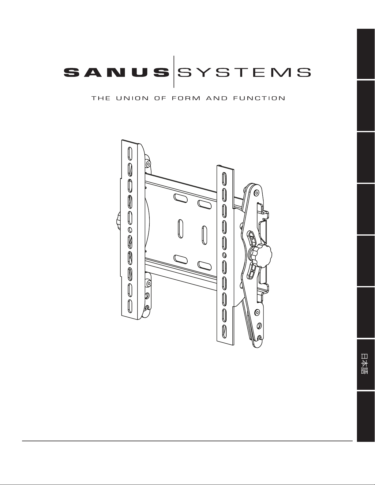
Assembly Instructions for Model: VM200
Thank you for choosing a Sanus Systems VisionMount™ wall mount. The VM200 is designed to mount up to 40” LCD TVs weighing less than 80 lbs
to a vertical wall. It will allow you to effortlessly tilt the TV ±20°.
Safety Warning: If you do not understand these directions, or have any doubts about the safety of the installation, please call a qualied contractor
or contact Sanus at 800.359.5520 or www.sanus.com. Check carefully to make sure that there are no missing or defective parts. Our customer service
representatives can quickly assist you with installation questions and missing or damaged parts. Replacement parts for products purchased through
authorized dealers will be shipped directly to you. Never use defective parts. Improper installation may cause damage or serious injury. Do not use this
product for any purpose that is not explicitly specied by Sanus Systems. Sanus Systems can not be liable for damage or injury caused by incorrect
mounting, incorrect assembly, or incorrect use. Please call Sanus Systems before returning products to the point of purchase.
Note: The supplied wall mounting hardware is not for metal stud or old cinder block walls. If you are uncertain about the nature of your wall, consult
an installation contractor. Sanus makes every effort to assure all necessary television mounting hardware is included. If the hardware you need is not
included please consult your local hardware store or call Sanus Systems.
Required Tools: Drill, 3/16” drill bit, (1/2” masonry bit for brick, concrete, or concrete block installations), socket set and a Phillips screw driver
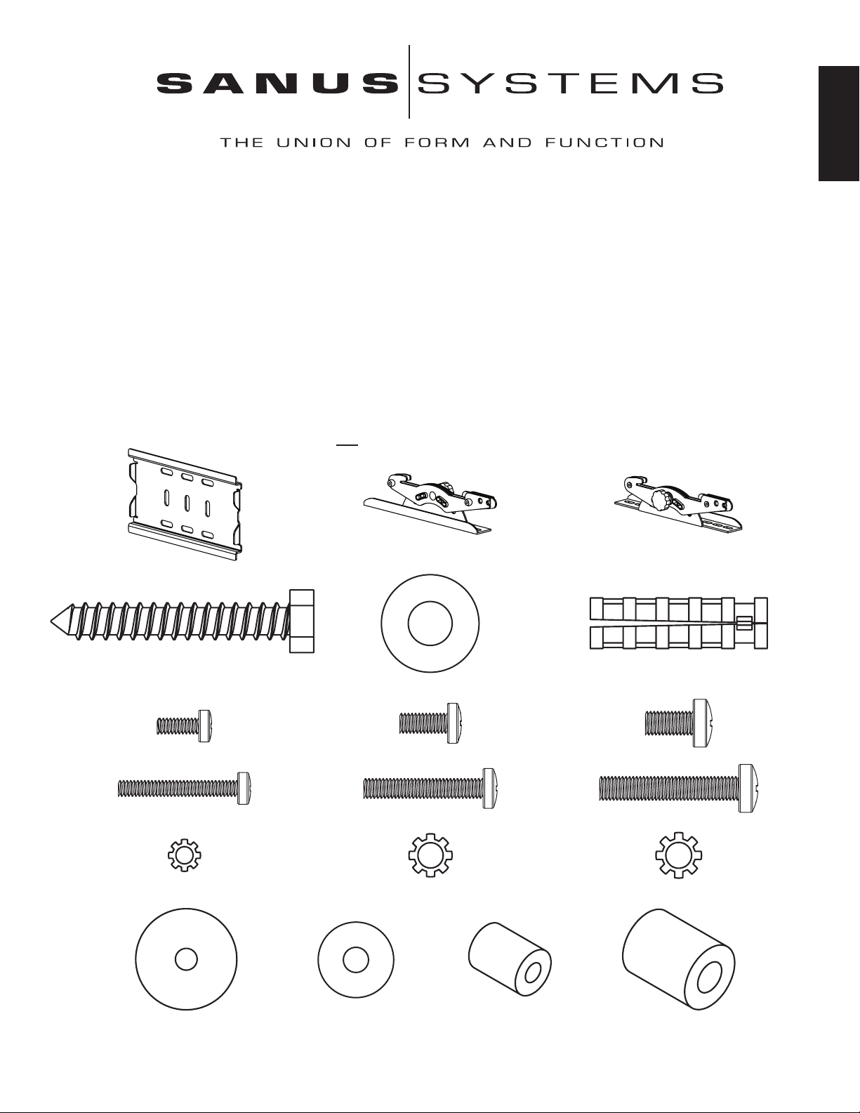
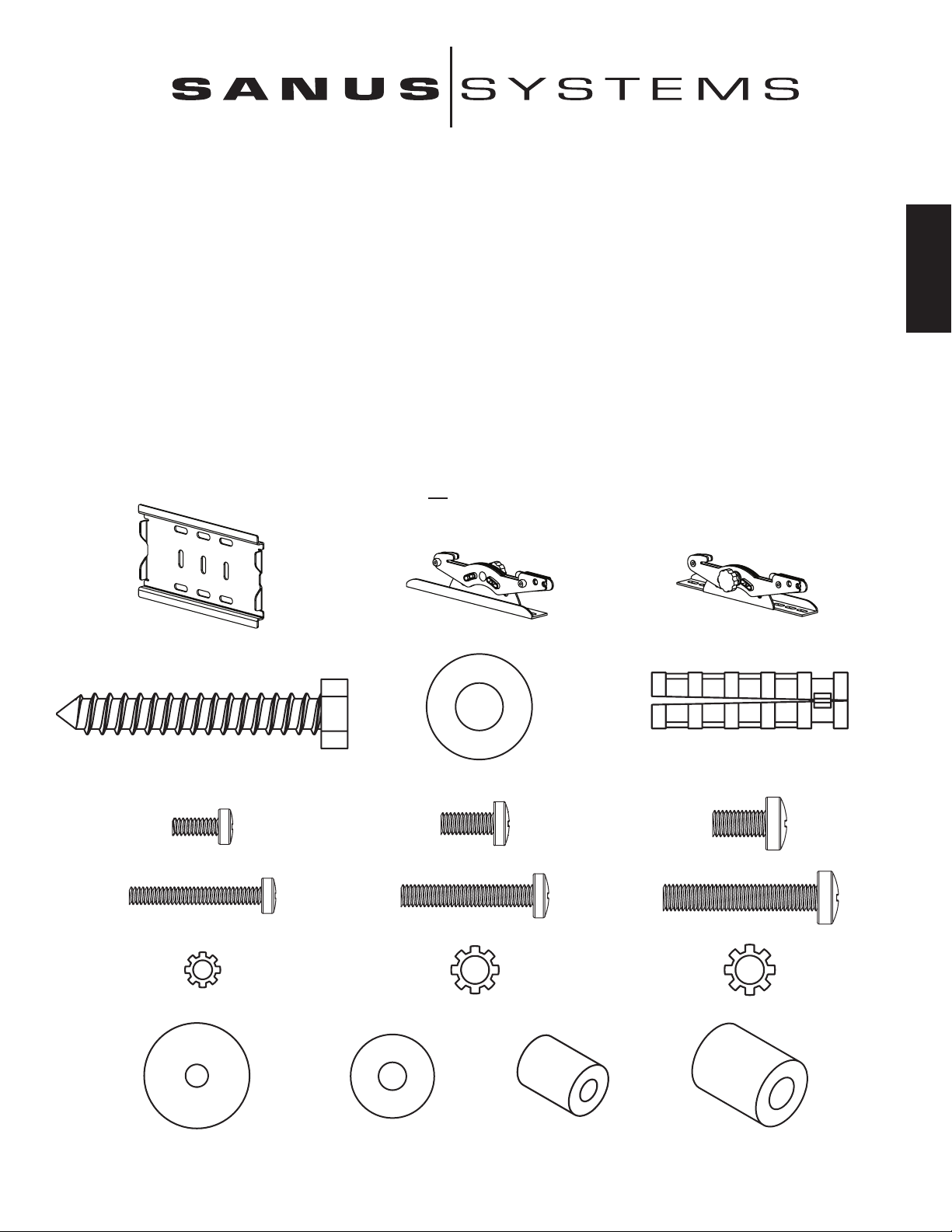
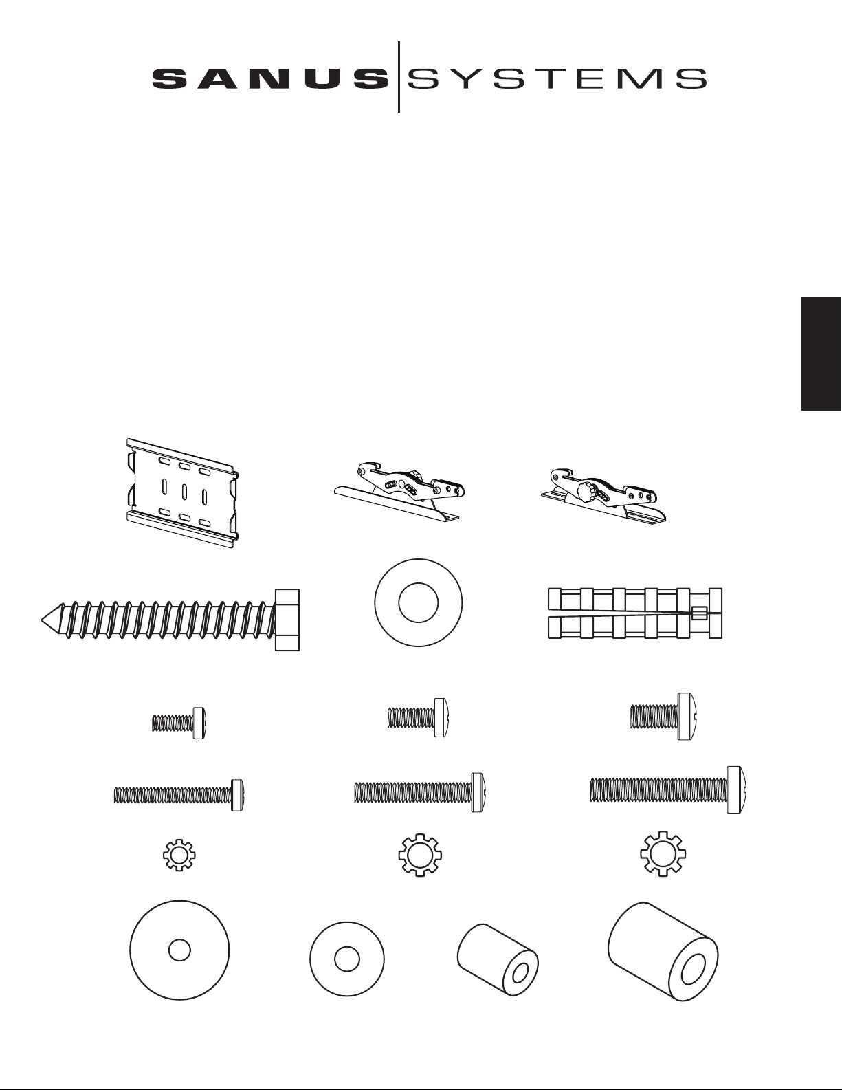
Supplied Parts and Hardware: Some parts not shown as actual size*
ENGLISH
(1) Left Monitor Bracket - b* (1) Right Monitor Bracket - c*
(1) Wall Plate - a*
(3) Lag Bolt - d (3) Concrete Anchor - f
(3) Lag Bolt Washer - e
TV Mounting Hardware:
(4) M4 x 10 mm Bolt - g (4) M5 x 12 mm Bolt - h (4) M6 x 12 mm Bolt - i
(4) M4 x 30 mm Bolt - j (4) M5 x 30 mm Bolt - k (4) M6 x 35 mm Bolt - l
(4) M4 Lock Washer - m (4) M5 Lock Washer - n (4) M6 Lock Washer - o
(4) M4/M5 Washer - p (4) M6 Washer - q (4) M4/M5 Spacer - r (4) M6 Spacer - s
Page 4
Step 1: Mount Monitor Brackets to a television with a at back
First, determine the diameter of the Bolt (g,h,i) your TV requires by hand threading them into the threaded insert on the back of the TV. If
you encounter any resistance stop immediately! Once you have determined the correct diameter, see the appropriate Diagram below. You
will thread the Bolt through the appropriate Lock Washer (m,n,o), the corresponding Washer (p,q), the Monitor Bracket (b,c), and nally
into the TV. Make sure the Monitor Brackets are vertically centered and level with each other. See the appropriate Diagram below.
ENGLISH
Note: For televisions with a curved back, or an obstruction near the threaded insert see Step 2.
M4 Diameter Bolt M6 Diameter Bolt
c b
g i
m o
p q
M5 Diameter Bolt Diagram 1
c
h
n
p
Page 5
Step 2: Mount Monitor Brackets to a television with a curved back or an obstruction near the threaded insert
First, determine the diameter of the Bolt (j,k,l) your TV requires by hand threading them into the threaded insert on the back of the TV.
If you encounter any resistance stop immediately! Once you have determined the correct diameter, see the appropriate Diagram below.
You will thread the Bolt through the appropriate Lock Washer (m,n,o), the corresponding Washer (p,q), the Monitor Bracket (b,c), a
Spacer (r,s), and nally into the TV. Make sure the Monitor Brackets are vertically centered and level with each other. See the appropriate
Diagram below.
M4 Diameter Bolt M6 Diameter Bolt
c b
j l
r m s o
p q
ENGLISH
M5 Diameter Bolt Diagram 2
c
r k
n
p
Page 6

Step 3: Mounting the Wall Plate - wood stud, brick, solid concrete and concrete block mounting options are provided
Wood Stud Installation:
The Wall Plate (a) must be installed into a single wood stud. Use the Wall Plate as a template mark a location on the wall, one in the top
row of slots and the other in the corresponding slot in the bottom row. Pre drill a 2.5” deep hole into the wood stud by using a 3/16” drill
bit. Make sure wall the Wall Plate is oriented to the at surface is against the wall. Attach the Wall Plate to the wall using two Lag Bolts
(d) and two Lag Bolt Washers (e). See Diagram 3a for assistance.
ENGLISH
Brick, solid concrete and concrete block installation:
Use the Wall Plate (a) as a template to mark 3 locations on the wall. Two in the top row of slots and one more centered in the bottom row.
Carefully pre-drill a 2.5” deep hole with a 1/2” masonry drill bit. Never drill into the mortar between blocks! Insert a Concrete
Anchor (f) into each pre-drilled hole so it is ush with the concrete/brick surface even if there is a layer of drywall or other material in
front. Attach the Wall Plate to the wall using three Lag Bolts (d) and three Lag Bolt Washers (e). See Diagram 3b for assistance.
Warning: Do not overtighten the Lag Bolts! Tighten Lag Bolts only until the Lag Bolt Washer is pulled rmly against
the Wall Plate.
Diagram 3a Diagram 3b
f
d e a d e a
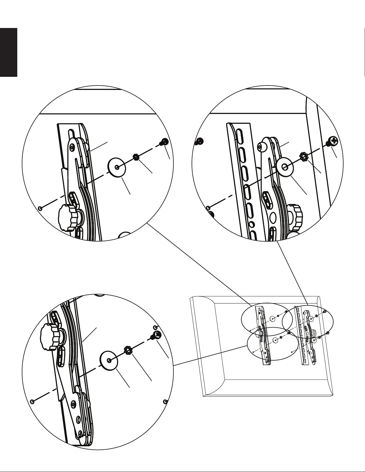
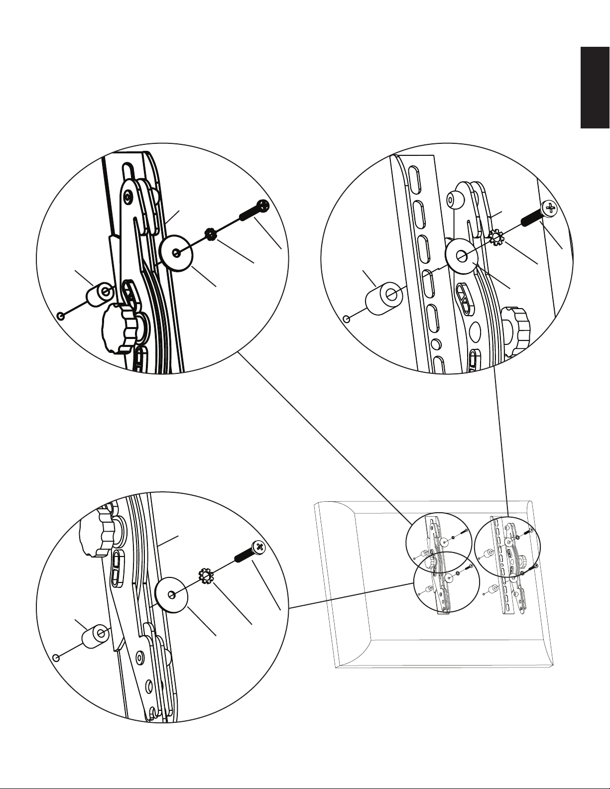
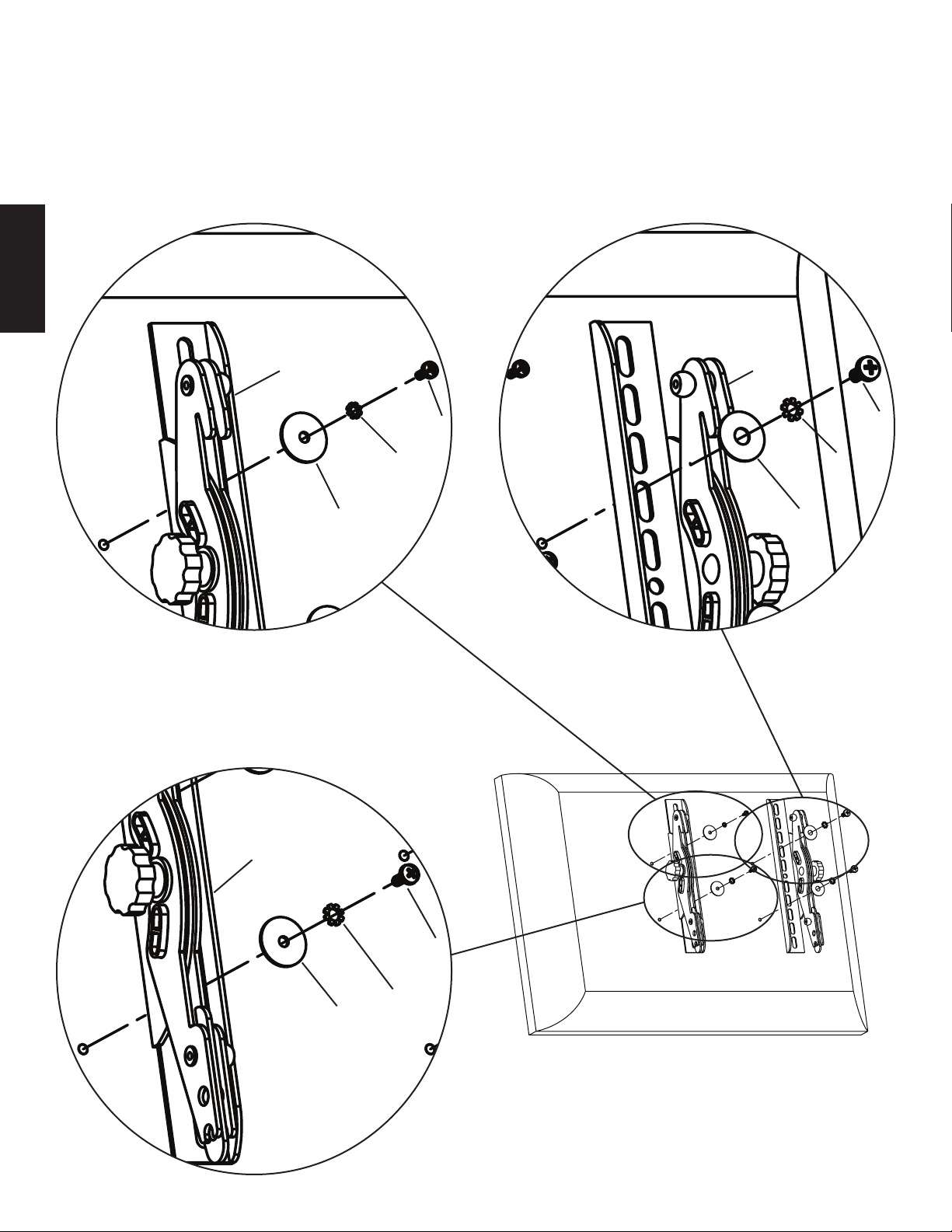
Step 4: Attach Monitor to Wall Plate
Rotate the latch handle into its most open position and hang the hooks of the Left and Right Monitor Brackets (b,c) over the tab on the
top of the Wall Plate (a) as shown in Diagram 4a. Once the Monitor Brackets are attached to the Wall Plate, rotate the latch handles on
each Monitor Bracket until they click into place. The tip of the latch handle should now be tucked up behind the tab on the bottom of the
Wall Plate as shown in the Detailed View of Diagram 4b. You may place a pad lock through the hole in the bottom of the latch handle if
you wish to add security to the installation.
Diagram 4a Diagram 4b Detailed View
b,c
bottom
tab
tip of
latch
handle
hole for
latch padlock
handle
Page 7
Instrucciones de armado del modelo: VM200
L A U N I Ó N D E F O R M A Y F U N C I Ó N
Gracias por elegir el soporte de pared VisionMount™ de Sanus Systems. El soporte VM200 ha sido diseñado para montar televisores con pantalla de
cristal líquido de 40 pulgadas con un peso de menos de 36,3 kg a una pared vertical. Permite inclinar el televisor ±20° sin mayor esfuerzo.
Advertencia de seguridad: Si no entiende estas instrucciones o si tiene alguna duda con respecto a la seguridad de la instalación, llame a un
contratista calicado o llámenos al 800.359.5520 (en EE.UU.) o al 31 (0) 20 5708938 (en Europa). También nos puede visitar en nuestro sitio
www.sanus.com. Revise cuidadosamente para asegurarse de que no hayan piezas faltantes o defectuosas. Nuestros representantes del servicio al
cliente pueden ayudarle a responder sus preguntas sobre la instalación o con respecto a las piezas faltantes o defectuosas. Las piezas de repuesto para
los productos comprados a través de un distribuidor autorizado se enviarán directamente a usted. Nunca use piezas que presenten algún defecto. La
instalación incorrecta puede provocar daño o lesiones graves. No use este producto para nes que no estén especicados explícitamente por Sanus
Systems. Sanus Systems no se hace responsable de los daños ni de las lesiones causadas por el montaje, armado o uso incorrectos. Sírvase llamar a
Sanus Systems antes de devolver los productos al punto de compra.
Nota: La tornillería de montaje suministrada no es para paredes con pies derechos de metal ni para paredes con bloques de cemento. Si se tiene alguna
duda sobre la naturaleza de la pared, consultar con un contratista. Sanus ha hecho todo lo posible para asegurar que se incluya toda la tornillería de
montaje necesaria. Si la tornillería que se necesita no se incluye, consultar en una ferretería local o llamar a Sanus Systems.
Herramientas necesarias: Taladro, broca de 3/16 pulgada, (broca para concreto de 1/2 pulgada para instalaciones sobre ladrillo, concreto o bloques
de hormigón), juego casquillos y un destornillador Phillips
Piezas y tornillería suministradas: Algunas piezas no se muestran del tamaño real*
(1) Soporte izquierdo de monitor - a* (1) Soporte derecho de monitor - b* (1) Placa adaptadora - c*
ESPAÑOL
(3) Tirafondos - d (3) Anclaje para concreto - f
(3) Arandela de tirafondo - e
Tornillería de montaje de TV:
(4) Perno M4 x 10 mm - g (4) Perno M5 x 12 mm - h (4) Perno M6 x 12 mm - i
(4) Perno M4 x 30 mm - j (4) Perno M5 x 30 mm - k (4) Perno M6 x 35 mm - I
(4) Arandela de seguridad M4 - m (4) Arandela de seguridad M5 - n (4) Arandela de seguridad M6 - o
(4) Arandela M4/M5 - p (4) Arandela M6 - q (4) Espaciador M4/M5 - r (4) Espaciador M6 - s
Page 8
Paso 1: Montar los soportes de monitor a un televisor con la parte trasera plana
Primero, determinar el diámetro del perno (g, h, i) que necesita el televisor. Para ello enroscar los pernos en el inserto roscado que se encuentra en la
parte trasera del televisor. ¡Si se encuentra alguna resistencia, parar inmediatamente! Una vez que se haya determinado el diámetro correcto, ver el
diagrama pertinente más abajo. Pasar el perno por la arandela de seguridad correcta (m, n, o), la arandela correspondiente (p, q), el soporte de monitor
(b, c) y nalmente insertarlo en el televisor. Asegurarse de que los soportes de monitor queden centrados verticalmente y nivelados entre ellos. Ver el
diagrama pertinente más abajo.
Nota: Para los televisores con la parte trasera curvada o con una obstrucción cerca del inserto roscado, ver el paso 2.
Perno de diámetro M4 Perno de diámetro M6
ESPAÑOL
c b
i
g
m o
p q
Perno de diámetro M5 Diagrama 1
c
h
n
p
Page 9

Paso 2: Montaje de soportes de monitor a un televisor con la parte trasera curvada o con una obstrucción cerca del inserto
roscado
Primero, determinar el diámetro del perno (j, k, l) que necesita el televisor. Para ello enroscar los pernos en el inserto roscado que se encuentra en la
parte trasera del televisor. ¡Si se encuentra alguna resistencia, parar inmediatamente! Una vez que se haya determinado el diámetro correcto, ver el
diagrama pertinente más abajo. Pasar el perno por la arandela de seguridad correcta (m, n, o), la arandela correspondiente (p, q), el soporte de monitor
(b, c), un espaciador (r, s) y nalmente insertarlo en el televisor. Asegurarse de que los soportes de monitor queden centrados verticalmente y nivelados
entre ellos. Ver el diagrama pertinente más abajo.
Perno de diámetro M4 Perno de diámetro M6
c b
j l
r m s o
p q
ESPAÑOL
Perno de diámetro M5 Diagrama 2
c
r k
n
p
Page 10

Paso 3: Montaje de la placa de pared - Se proporcionan opciones para montaje sobre pie derecho de madera, ladrillo, concreto sólido
y bloque de hormigón
Instalación sobre pie derecho de madera:
La placa de pared (a) se debe instalar a un solo pie derecho de madera. Utilizar la placa de pared como plantilla para marcar un punto en la pared, uno
en la hilera superior de ranuras y otro en la ranura correspondiente en la hilera inferior. Perforar con antelación un agujero profundo de 6,4 cm en el pie
derecho utilizando una broca de 3/16 pulgada. Asegurarse de que la placa de pared quede orientada hacia la supercie plana, contra la pared. Conectar
la placa en la pared utilizando dos tirafondos (d) y dos arandelas de tirafondo (e). Ver el diagrama 3a para más ayuda.
Instalación en ladrillo, concreto y bloque de hormigón:
Utilizar la placa de pared (a) como una plantilla para marcar 3 posiciones en la pared. Dos en la hilera superior de ranuras y una más centrada en la hilera
inferior. Perforar cuidadosamente un agujero profundo de 6,4 cm con una broca para concreto de 1/2 pulgada. ¡Nunca perforar en el cemento
entre los bloques! Insertar un anclaje para concreto (f) en cada agujero perforado, de manera que quede a ras con la supercie de concreto/ladrillo,
incluso si hubiera una capa de yeso u otro material antes. Conectar la placa en la pared utilizando tres tirafondos (d) y tres arandelas de tirafondo (e).
Ver el diagrama 3b para más ayuda.
ESPAÑOL
Advertencia: ¡No apretar demasiado los tirafondos! Apretar los tirafondos sólo hasta que la arandela quede bien rme contra
la placa de pared.
Diagrama 3a Diagrama 3b
f
d e a d e a
Paso 4: Conectar el monitor a la placa de pared
Girar la manija de bloqueo a su posición más abierta y colgar los ganchos de los soportes de monitor izquierdo y derecho (b, c) sobre la pestaña en la
parte superior de la placa de pared (a), como se ilustra en el diagrama 4a. Una vez que los soportes de monitor se conectan a la placa de pared, girar las
manijas de bloqueo en cada soporte hasta que encajen bien en su lugar. La punta de la manija de bloqueo ahora se debe meter detrás de la pestaña en la
parte inferior de la placa de pared, como se ilustra en la vista detallada del diagrama 4b. Se puede pasar un candado por el agujero en la parte inferior
de la manija de bloqueo si se desea agregar seguridad a la instalación.
Diagrama 4a Diagrama 4b Vista detallada
b,c
pestaña
inferior
punta de
manija de
bloqueo
candado agujero para
de bloqueo candado
Page 11
Montageanweisungen für das Modell: VM200
Wir freuen uns, dass Sie sich für eine VisionMount™-Wandhalterung von Sanus Systems entschieden haben. Das Gerät VM200 ist zur Montage von LCD-Flachbildfernsehern
mit einer Bildschirmdiagonale von 40 Zoll und einem Gewicht von höchstens 36,3 kg an einer vertikalen Wand vorgesehen. Der Fernseher lässt sich mühelos um ± 20° neigen.
Sicherheitshinweis: Wenn Sie diese Anweisungen nicht verstehen oder Zweifel an der Sicherheit der Montage haben, rufen Sie einen Fachmann an oder kontaktieren
Sie Sanus Systems telefonisch unter +1-800-359-5520 (USA) oder +31-(0)20-570-8938 (Europa). Oder besuchen Sie uns im Internet unter www.sanus.com. Überprüfen
Sie die Zubehörteile sorgfältig, um sicherzugehen, dass keine Teile fehlen oder beschädigt sind. Unsere Kundendienstmitarbeiter können Ihnen bei Fragen zur Montage
und bei fehlenden oder beschädigten Teilen schnell weiterhelfen. Ersatzteile für bei autorisierten Fachhändlern gekaufte Produkte werden direkt an Ihre Adresse versandt.
Verwenden Sie niemals beschädigte Teile! Unsachgemäße Montage kann Schäden am Gerät und schwere Verletzungen hervorrufen! Verwenden Sie das Produkt nicht
für andere als von Sanus Systems explizit genannte Zwecke. Sanus Systems haftet nicht für Schäden oder Verletzungen, die durch unsachgemäße Montage, fehlerhaften
Zusammenbau oder unsachgemäße Nutzung entstehen. Bitte rufen Sie Sanus Systems an, bevor Sie Produkte beim Händler reklamieren.
Hinweis: Das mitgelieferte Montagezubehör eignet sich nicht für Trockenwände mit Ständerprolen oder Wände aus Holzblocksteinen. Bei Zweifeln an der Bauweise
Ihrer Wand wenden Sie sich an einen Experten. Sanus Systems bemüht sich stets, sicherzustellen, dass das erforderliche Montagezubehör im Lieferumfang enthalten ist.
Wenn das erforderliche Zubehör nicht im Lieferumfang enthalten ist, wenden Sie sich bitte an Ihren Fachhändler vor Ort oder an Sanus Systems.
Erforderliche Werkzeuge: Bohrmaschine, Bohrer 3/16 Zoll, Steinbohrer 1/2 Zoll für Ziegel, Beton oder Betonsteine, Steckschlüsselsatz, Kreuzschlitzschraubendreher.
Mitgelieferte Teile und Zubehör: Mit * markierte Teile sind verkleinert dargestellt.
(1) Linke Monitorklammer – b* (1) Rechte Monitorklammer – c*
(1) Wandplatte – a*
DEUTSCH
(3) Holzschraube – d (3) Holzschraubenunterlegscheibe – e (3) Betondübel – f
Montagezubehör für den Fernseher:
(4) Schraube M4 x 10 mm – g (4) Schraube M5 x 12 mm – h (4) Schraube M6 x 12 mm – i
(4) Schraube M4 x 30 mm – j (4) Schraube M5 x 30 mm – k (4) Schraube M6 x 35 mm – l
(4) Sicherungsscheibe M4 – m (4) Sicherungsscheibe M5 – n (4) Sicherungsscheibe M6 – o
(4) Unterlegscheibe M4/M5 – p (4) Unterlegscheibe M6 – q (4) Distanzstück M4/M5 – r (4) Distanzstück M6 – s
Page 12

Schritt 1: Montage der Monitorklammern an einem Fernseher mit acher Rückseite
Zunächst die erforderliche Schraubengröße (g, h, i) für den Fernseher durch probeweises Eindrehen der Schrauben in die Gewindeeinsätze an der Rückseite des
Fernseher eindrehen. Wenn ein Widerstand zu spüren ist, sofort aufhören! Sobald der korrekte Durchmesser ermittelt ist, die entsprechende untenstehende Abbildung
beachten. Eine Schraube durch die entsprechende Sicherungsscheibe (m, n, o), die dazugehörige Unterlegscheibe (p, q), die Monitorklammer (b, c) und schließlich in den
Fernseher eindrehen. Die Monitorklammern müssen vertikal mittig und aufeinander ausgerichtet sein. Die entsprechende unten stehende Abbildung beachten.
Hinweis: Hinweise zu Fernsehern mit einer gekrümmten Rückseite oder einem Hindernis am Gewindeeinsatz nden Sie in Schritt 2.
Schraube M4 Schraube M6
c b
g i
DEUTSCH
m o
p q
Schraube M5 Abbildung 1
c
h
n
p
Page 13

Schritt 2: Montage der Monitorklammern für einen Fernseher mit einer gekrümmten Rückseite oder einem Hindernis am Gewindeeinsatz
Zunächst die erforderliche Schraubengröße (j, k, l) für den Fernseher durch probeweises Eindrehen der Schrauben in die Gewindeeinsätze an der Rückseite des Fernsehers
bestimmen. Wenn ein Widerstand zu spüren ist, sofort aufhören! Sobald der korrekte Durchmesser ermittelt ist, die entsprechende untenstehende Abbildung beachten. Eine
Schraube durch die entsprechende Sicherungsscheibe (m, n, o), die dazugehörige Unterlegscheibe (p, q), die Monitorklammer (b, c), das Distanzstück (r, s) und schließlich
in den Fernseher eindrehen. Die Monitorklammern müssen vertikal mittig und aufeinander ausgerichtet sein. Die entsprechende untenstehende Abbildung beachten.
Schraube M4 Schraube M6
c b
j l
r m s o
p q
DEUTSCH
Schraube M5 Abbildung 2
c
r k
n
p
Page 14

Schritt 3: Montage der Wandplatte – Es wird Zubehör zur Montage an Holzbalkenträgern, Ziegelwänden, Massivbeton und Betonsteinen mitgeliefert.
Montage an einem Holzbalkenträger:
Die Wandplatte (a) muss an einem Holzbalkenträger montiert werden. Die Wandplatte als Schablone für die Positionierung auf der Wand benutzen. Eine Schraube
muss in der oberen Schlitzreihe und in die andere in dem entsprechenden Schlitz der unteren Reihe sitzen. Mit einem Bohrer 3/16 Zoll ein Loch mit einer Tiefe von
6,4 cm in den Holzbalkenträger vorbohren. Die Wandplatte muss mit der achen Seite zur Wand zeigen. Die Wandplatte mit zwei Holzschrauben (d) und zwei Holzschra
ubenunterlegscheiben (e) an der Wand montieren. Siehe Abbildung 3a.
Montage bei Ziegelwänden, Massivbeton und Betonsteinen:
Die Wandplatte (a) als Schablone verwenden, um die drei Bohrungen an der Wand zu markieren. Zwei Bohrungen in die obere Reihe der Schlitze bohren und eine weitere
mittig in die untere Reihe. Vorsichtig ein 6,4 cm tiefes Loch mit einem Steinbohrer 1/2 Zoll vorbohren. Niemals in die Mörtelfuge zwischen den Betonsteinen
bohren! Einen Betondübel (f) in das vorgebohrte Loch einschieben, so dass er bündig mit der Beton- bzw. Ziegelkante abschließt, selbst wenn sich davor noch eine
Trockenwand oder anderes Material bendet. Die Wandplatte mit drei Holzschrauben (d) und drei Holzschraubenunterlegscheiben (e) an der Wand montieren. Siehe
Abbildung 3b.
Vorsicht: Die Holzschrauben nicht überdrehen! Die Holzschrauben nur so weit festziehen, dass die Holzschraubenunterlegscheibe fest gegen
die Wandplatte drückt.
Abbildung 3a Abbildung 3b
DEUTSCH
f
d e a d e a
Schritt 4: Montage des Monitors an der Wandplatte
Den Arretiergriff durch Drehung ganz öffnen und die Haken der linken und rechten Monitorklammer (b, c) über die Nase an der Oberseite der Wandplatte (a) wie in
Abbildung 4a hängen. Sobald die Monitorklammern mit der Wandplatte verbunden sind, die Arretiergriffe der Monitorklammern drehen, bis sie hörbar einrasten. Die
Spitze des Arretiergriffs muss nun hinter der Nase an der Unterkante der Wandplatte wie in der Detailansicht von Abbildung 4b liegen. Durch die Bohrung am unteren
Rand des Arretiergriffs kann der Monitor bei Bedarf zusätzlich mit einem Vorhängeschloss gesichert werden.
Abbildung 4a Abbildung 4b Detailansicht
b, c
untere
Nase
Spitze des
Arretier griffs
Bohrung für das
Vorhängeschloss
Arretiergriff
Page 15

Instructions d’assemblage pour le modèle : VM200
Nous vous remercions d’avoir choisi un montant mural VisionMount™ de Sanus Systems. Le VM200 est conçu pour xer au mur des téléviseurs à
afchage LCD mesurant jusqu’à 40 pouces et d’un poids maximal de 36,3 kg. Il vous permettra d’incliner sans effort votre téléviseur de ±20 °.
Précautions de sécurité : Si vous ne comprenez pas ces instructions ou si vous avez un doute quant à la sécurité de cette installation, veuillez faire
appel à un technicien qualié ou communiquez avec Sanus en composant le 1-800-359-5520 (aux É.-U.), ou le 31 (0) 20 5708938 (pour l’Europe). Vous
pouvez aussi allez sur notre site Web au www.sanus.com. Vériez soigneusement qu’il n’y a aucune pièce manquante ou défectueuse. Les représentants
de notre service à la clientèle peuvent répondre rapidement à toute question concernant l’installation ou les pièces manquantes ou endommagées. Les
pièces de rechange de produits achetés auprès de distributeurs agréés vous seront livrées directement. N’utilisez jamais de pièces défectueuses. Une
installation incorrecte peut entraîner des dommages ou des blessures graves. Ce produit ne doit être utilisé que pour des usages explicitement spéciés
par Sanus Systems. Sanus Systems ne pourra être tenu responsable de dommages ou de blessures dus à un montage incorrect, à un assemblage incorrect
ou à un usage incorrect. Veuillez contacter Sanus Systems avant de retourner les produits au lieu de vente.
Remarque : Le matériel pour montage mural fourni n’est pas adapté aux cloisons à charpente métallique ni aux anciennes cloisons en blocs de cendre.
Si vous n’êtes pas certain de la nature de votre cloison, veuillez consulter un entrepreneur. Sanus prend soin d’inclure toute la visserie nécessaire au
montage d’un téléviseur. Si toutefois la visserie dont vous avez besoin n’est pas incluse, consultez une quincaillerie locale ou contactez directement
Sanus Systems.
Outils nécessaires : Perceuse, mèche de 3/16 pouce (mèche à maçonnerie de 1/2 pouce permettant de percer les surfaces en béton, de brique ou de
blocs en béton), jeu de douilles, tournevis cruciforme
Pièces et matériel fournis : Certaines pièces ne sont pas illustrées grandeur réelle*
FRANÇAIS
(1) Plaque murale - a* (1) Support gauche du moniteur - b* (1) Support droit du moniteur - c*
(3) Tire-fond - d (3) Boulon d’ancrage pour béton - f
(3) Rondelle pour tire-fond - e
Visserie de montage du téléviseur :
(4) Boulon M4 x 10 mm - g (4) Boulon M5 x 12 mm - h (4) Boulon M6 x 12 mm - i
(4) Boulon M4 x 30 mm - j (4) Boulon M5 x 30 mm - k (4) Boulon M6 x 35 mm - l
(4) Rondelle-frein M4 - m (4) Rondelle-frein M5 - n (4) Rondelle-frein M6 - o
(4) Rondelle M4/M5 - p (4) Rondelle M6 - q (4) Entretoise M4/M5 - r (4) Entretoise M6 - s
Page 16

Etape 1 : Montage des supports du moniteur sur un téléviseur à panneau arrière plat
Déterminez d’abord le diamètre du boulon (g, h, i) que votre téléviseur nécessite en les vissant à la main dans l’insert leté du panneau arrière
du téléviseur. Si vous ressentez une résistance quelconque, arrêtez immédiatement ! Une fois le bon diamètre déterminé, reportez-vous au schéma
approprié ci-dessous. Vous devez faire passer le boulon dans la bonne rondelle-frein (m, n, o), puis dans la rondelle correspondante (p, q) et dans le
support du moniteur (b, c), et faire nalement passer le tout dans le téléviseur. Assurez-vous que les supports du moniteur sont centrés verticalement et
qu’ils sont tous deux au même niveau. Reportez-vous au schéma approprié ci-dessous.
Remarque : Pour les téléviseurs à panneau arrière courbé ou ceux dont l’insert leté est difcilement accessible, reportez-vous
à l’étape 2.
Boulon de diamètre M4 Boulon de diamètre M6
c b
i
g
m o
p q
FRANÇAIS
Boulon de diamètre M5 Schéma 1
c
h
n
p
Page 17

Etape 2 : Montage des supports du moniteur sur un téléviseur à panneau arrière courbé ou sur un téléviseur dont l’insert leté
est difcilement accessible
Déterminez d’abord le diamètre du boulon (j, k, l) que votre téléviseur nécessite en les vissant à la main dans l’insert leté du panneau arrière
du téléviseur. Si vous ressentez une résistance quelconque, arrêtez immédiatement ! Une fois le bon diamètre déterminé, reportez-vous au schéma
approprié ci-dessous. Vous devez faire passer le boulon dans la bonne rondelle-frein (m, n, o), puis dans la rondelle correspondante (p, q), dans le
support du moniteur (b, c) et dans une entretoise (r, s) et faire nalement passer le tout dans le téléviseur. Assurez-vous que les supports du moniteur
sont centrés verticalement et qu’ils sont tous deux au même niveau. Reportez-vous au schéma approprié ci-dessous.
Boulon de diamètre M4 Boulon de diamètre M6
c b
j l
r m s o
p q
FRANÇAIS
Boulon de diamètre M5 Schéma 2
c
r
k
n
p
Page 18

Etape 3 : Montage de la plaque murale - Les options de montage sont les suivantes : ossature de bois, brique, béton monolithe et bloc de béton.
Installation sur ossature de bois :
La plaque murale (a) doit être installée sur un montant simple en bois. Servez-vous de la plaque murale comme modèle an de marquer un emplacement
sur le mur, un sur la rangée supérieure des fentes et l’autre sur la fente correspondante de la rangée inférieure. Prépercez un trou de 6,4 cm de profondeur
dans le montant en bois à l’aide d’une mèche de 3/16 pouce. Assurez-vous que la plaque murale est orientée de façon à ce que la surface plane soit
contre le mur. Fixez la plaque murale sur le mur à l’aide des deux tire-fonds (d) et des deux rondelles de tire-fond (e). Reportez-vous au schéma 3a si
vous avez besoin d’aide.
Installation sur brique, béton monolithe et bloc de béton :
Servez-vous de la plaque murale (a) comme modèle pour marquer 3 emplacements sur le mur. Deux sur la rangée supérieure des fentes et un autre
au centre de la rangée inférieure. Prépercez un trou de 6,4 cm de profondeur avec une mèche à maçonnerie de 1/2 pouce. Ne percez jamais dans
le mortier situé entre les blocs ! Insérez un boulon d’ancrage pour béton (f) dans chacun des trous prépercés de manière à ce qu’il afeure
complètement la surface du béton même si elle est recouverte d’une couche de cloison sèche ou de tout autre matériau sur le devant. Fixez la plaque
murale au mur à l’aide des trois tire-fonds (d) et des trois rondelles de tire-fond (e). Reportez-vous au schéma 3b si vous avez besoin d’aide.
Avertissement : Ne serrez pas excessivement les tire-fonds ! Ne serrez les tire-fonds que jusqu’à ce que la rondelle soit tirée
fermement contre la plaque murale.
Schéma 3a Schéma 3b
f
FRANÇAIS
d e a d e a
Etape 4 : Fixation du moniteur à la plaque murale
Faites pivoter la poignée de verrouillage à une position d’ouverture maximale et suspendez les crochets des supports gauche et droit (b, c) du moniteur
sur la patte sur le dessus de la plaque murale (a) tel qu’indiqué sur le schéma 4a. Une fois les supports du moniteur xés à la plaque murale, faites
pivoter les poignées de verrouillage sur chacun des supports du moniteur jusqu’à ce qu’ils s’enclenchent. L’embout de la poignée de verrouillage doit
se trouver à présent derrière la patte en bas de la plaque murale tel qu’indiqué à la vue détaillée du schéma 4b. Vous pouvez placer un cadenas dans le
trou sur la partie inférieure de la poignée de verrouillage pour utiliser l’installation en toute sécurité.
Schéma 4a Schéma 4b Vue détaillée
b, c
patte
inférieure
embout
de la
poignée
verrouillage
trou destiné
poignée de au cadenas
verrouillage
Page 19

Istruzioni di montaggio per il modello: VM200
Grazie per aver scelto un sistema di montaggio per parete Sanus Systems VisionMount™. Il VM200 è progettato per montare televisiori LCD no a
40 pollici che pesano no a 36,3 kg su una parete verticale. Consente di inclinare la TV di ±20°.
Avvertenza sulla sicurezza: se non si comprendono queste istruzioni o si hanno dubbi sulla sicurezza dell’installazione, rivolgersi a un installatore
specializzato o contattare la Sanus al numero verde USA 800.359.5520 o, in Europa, al numero +31 (0) 20 5708938. È anche possibile visitare il
sito www.sanus.com. Controllare con attenzione che non vi siano parti mancanti o difettose. Il nostro servizio di assistenza clienti potrà rispondere
rapidamente alle domande relative all’installazione o alle parti mancanti o danneggiate. Le parti di ricambio per i prodotti acquistati attraverso i
rivenditori autorizzati vengono spedite direttamente al cliente. Non utilizzare parti difettose. L’installazione errata può causare danni o lesioni gravi.
Non utilizzare questo prodotto per scopi diversi da quelli specicamente indicati dalla Sanus Systems. La Sanus Systems non è responsabile di danni o
lesioni causati da montaggio o utilizzo non corretti. Chiamare la Sanus Systems prima di riportare i prodotti al punto vendita.
Nota: la minuteria metallica fornita per il montaggio a parete non è adatta a travi metalliche o a vecchie pareti di blocchi di calcestruzzo. Se non si è
sicuri della natura della parete, consultare un rappresentante locale. La Sanus fa ogni sforzo possibile per assicurare che sia inclusa tutta la minuteria
metallica necessaria per il televisore.
Strumenti necessari: trapano, punta per trapano da 3/16 pollice, (punta per muratura da 1/2 pollice per mattoni, cemento o costruzioni con blocchi
di cemento), serie di chiavi, cacciavite Phillips
Parti e minuteria metallica fornite: in gura, alcune parti non sono delle dimensioni reali*
(1) staffa sinistra per monitor - b* (1) staffa destra per monitor - c*
(1) piastra per parete - a*
(3) tirafondi – d (3) ancora per cemento - f
(3) rondella per tirafondo - e
Minuteria per montaggio TV:
(4) M4 da 10 mm - g (4) bullone M5 da 12 mm - h (4) bullone M6 da 12 mm - i
(4) M4 da 30 mm - j (4) bullone M5 da 30 mm - k (4) bullone M6 x 35 mm - l
(4) controrondella M4 - m (4) controrondella M5 - n (4) controrondella M6 - o
ITALIANO
(4) rondella M4/M5 - p (4) rondella M6 - q (4) distanziale M4/M5 - r (4) distanziale M6 - s
Page 20

Fase 1: montare le staffe del monitor al televisore con retro piatto
Innanzitutto, stabilire il diametro dei bulloni (g, h, i) che devono essere avvitati a mano alla TV nell’inserto lettato sul retro della TV.
Se si incontrano delle resistenze, bloccarsi immediatamente! Una volta determinato il diametro corretto, vedere la Figura appropriata che
segue. Il bullone viene avvitato attraverso la controrondella appropriata (m, n, o), la rondella corrispondente (p, q), la staffa del monitor
(b, c) e nale nella TV. Assicurarsi che le staffe per monitor siano centrate verticalmente e a livello l’una con l’altra. Vedere la Figura
appropriata che segue.
Nota: per televisori con retro curvo o per un’ostruzione accanto all’inserto lettato, vedere la Fase 2.
Bullone di diametro M4 Bullone di diametro M6
c b
g i
m o
p q
ITALIANO
Bullone di diametro M5 Figura 1
c
h
n
p
Page 21

Fase 2: montare le staffe del monitor al televisore con retro curvo o un’ostruzione accanto all’inserto lettato
Innanzitutto, stabilire il diametro dei bulloni (j, k, l) che devono essere avvitati a mano alla TV nell’inserto lettato sul retro della TV. Se
si incontrano delle resistenze, bloccarsi immediatamente! Una volta determinato il diametro corretto, vedere la Figura appropriata che
segue. Il bullone viene avvitato attraverso la controrondella appropriata (m, n, o), la rondella corrispondente (p, q), la staffa del monitor
(b, c), un distanziale (r, s) e inne nella TV. Assicurarsi che le staffe per monitor siano centrate verticalmente e a livello l’una con l’altra.
Vedere la Figura appropriata che segue.
Bullone di diametro M4 Bullone di diametro M6
c b
j l
r m s o
p q
Bullone di diametro M5 Figura 2
c
r k
n
p
ITALIANO
Page 22

Fase 3: montare la piastra a parete - sono disponibili le opzioni di montaggio su assi di legno, mattoni, cemento e blocchi
di cemento
Installazione su assi di legno:
La piastra per parete (a) deve essere installata in una singola asse di legno. Utilizzare la piastra per parete come maschera per contrassegnare
una posizione sulla parete, una nella la superiore di alloggiamenti e l’altra nell’alloggiamento corrispondente della la inferiore. Forare
in precedenza un foro ad una profondità di 6,4 cm sull’asse di legno usando una punta per trapano da 3/16 pollice. Assicurarsi che la
piastra per parete sia orientata sulla supercie piatta e si trovi contro la parete. Collegare la piastra per parete alla parete usando i due
tirafondi (d) e le due rondelle per tirafondo (e). Vedere la Figura 3a per assistenza.
Installazione per mattone, cemento solido e blocco di cemento:
Utilizzare la piastra per parete (a) come maschera per contrassegnare 3 posizioni sulla parete. Due nella la superiore degli alloggiamenti
e un altro più centrato nella la inferiore. Forare in precedenza con attenzione un foro ad una profondità di 6,4 cm usando una punta per
muratura da 1/2 pollice. Non trapanare mai nel cemento tra i blocchi! Inserire un’ancora per cemento (f) in ogni foro preforato in
modo che sia sistemata a livello con la supercie di cemento/mattone anche se vi è uno strato di stucco o altro materiale davanti. Collegare
la piastra per parete alla parete usando i tre tirafondi (d) e le tre rondelle per tirafondo (e). Vedere la Figura 3b per assistenza.
Avvertenza: non serrare eccessivamente i tirafondi! Serrare i tirafondi solo no a quando la rondella del tirafondi
non viene ben tirata contro la piastra per parete.
Figura 3a Figura 3b
f
d e a d e a
Fase 4: installare il monitor alla piastra per parete
Ruotare la maniglia con gancio nella posizione di maggiore apertura e agganciare i ganci sulle staffe sinistra e destra del monitor
(b, c) sopra la linguetta sulla parte superiore della piastra per parete (a) come mostrato nella Figura 4a. Una volta che le staffe per monitor
ITALIANO
sono attaccate alla piastra per parete, ruotare le maniglie per gancio su ogni staffa per monitor no a quando non fa clic in posizione. La
punta della maniglia con gancio deve essere ripiegata dietro la linguetta sulla parte inferiore della piastra per parete come mostrato nella
vista dettagliata della Figura 4b. Attraverso il foro è possibile inserire un lucchetto nella parte inferiore della maniglia con gancio se si
desidera aggiungere sicurezza all’installazione.
Figura 4a Figura 4b
b,c
parte
inferiore
linguetta
punta
della
maniglia
gancio
Vista dettagliata
foro per
gancio lucchetto
maniglia
Page 23

Инструкция по сборке крепления модели VM200
Благодарим Вас за приобретение настенного крепления Sanus Systems VisionMount™. Крепление VM200 предназначено для
установки жидкокристаллических телевизоров с диагональю до 40 дюймов, весом до 36,3 кг на вертикальные стены. Крепление позволяет
без усилий наклонить телевизор на угол до ±20°.
Внимание! Если Вам непонятны приведенные ниже инструкции, или если возникают любые сомнения по поводу безопасности использования
установленного устройства, обратитесь к квалифицированному специалисту или в компанию Sanus по телефону 800-359-5520 (США)
или 31 (0) 20 5708938 (Европа). Вы также можете посетить наш веб-сайт www.sanus.com. Тщательно проверьте наличие всех деталей и
отсутствие заводского брака. Сотрудники нашей службы работы с покупателями незамедлительно помогут Вам решить все вопросы,
связанные с установкой устройства, а также с недостающими либо поврежденными деталями. Запасные части к изделиям компании
Sanus, приобретенным через уполномоченных агентов по продаже, будут доставлены непосредственно по указанному Вами адресу. Не
используйте бракованные детали. Неправильная установка устройства может привести к травмированию людей и порче имущества. Это
изделие может применяться исключительно в целях, прямо указанных производителем. Компания Sanus Systems не несет ответственности
за вред здоровью или материальный ущерб, причиненный вследствие неправильной сборки, монтажа и эксплуатации устройства. Решив
вернуть изделие в магазин, где Вы его приобрели, обратитесь, пожалуйста, сначала в компанию Sanus Systems.
Примечание: Настоящее крепежное оборудование не предназначено для монтажа на стенах со стальным каркасом или на старых
шлакобетонных стенах. Если Вы не можете с уверенностью судить о конструкции стены, обратитесь в строительную организацию.
Компания Sanus прилагает все усилия к тому, чтобы поставлять все необходимое крепежное оборудование для телевизоров. Если нужной
Вам детали в комплекте нет, обратитесь в магазин бытовой техники или в компанию Sanus Systems.
Необходимые инструменты: Дрель, сверло на 3/16 дюйма, (тонкостенная алмазная коронка на 1/2 дюйма для установки на кирпичной,
монолитной бетонной или панельной бетонной стене), набор торцовых насадок, крестообразная отвертка.
Детали устройства и крепежные детали: Некоторые детали изображены в масштабе*
Левая крепежная скоба для монитора (b*) – 1 шт. Правая крепежная скоба для монитора (c*) – 1 шт.
Настенная крепежная пластина (a*) – 1 шт.
Шуруп под ключ (d) – 3 шт. Дюбель для бетона (f) – 3 шт.
Шайба для шурупа под ключ (e) – 3 шт.
Крепежное оборудование для телевизора:
Винт M4 x 10мм (g) – 4 шт. Винт M5 x 12мм (h) – 4 шт. Винт M6 x 12мм (i) – 4 шт.
Винт M4 x 30мм (j) – 4 шт. Винт M5 x 30мм (k) – 4 шт. Винт M6 x 35мм (l) – 4 шт.
PYCCKO
Шайба стонорная M4 (m) – 4 шт. Шайба стонорная M5 (n) – 4 шт. Шайба стонорная M6 (o) – 4 шт.
Шайба M4/М5 (p) – 4 шт. Шайба M6 (q) – 4 шт. Шайба установочная M4/М5 (r) – 4 шт. Шайба установочная М6 (s) – 4 шт.
Page 24

Шаг 1. Прикрепление крепежных скоб к телевизору с плоской задней панелью.
Сначала нужно определить диаметр винта (g, h, i) , который подходит для Вашего телевизора. Для этого попробуйте вручную
ввинтить каждый винт в заднюю панель телевизора. Почувствовав сопротивление, немедленно прекратите ввинчивать винт!
Определив нужный диаметр, рассмотрите соответствующий рисунок ниже. Винт следует завинтить через соответствующую
стонорную шайбу (m, n, o), шайбу (p, q) и крепежную скобу для монитора (b, c) в заднюю панель телевизора. Крепежные
скобы должны быть прикреплены на одном уровне и центрированы по вертикали. См. соответствующий рисунок ниже.
Примечание: если задняя панель телевизора искривлена или возле вставки с резьбой имеется мешающий выступ, см. шаг 2.
Винт диаметра M4 Винт диаметра M6
c b
g i
m o
p q
Винт диаметра M5 Рисунок 1
PYCCKO
c
h
n
p
Page 25

Шаг 2. Прикрепление крепежных скоб к телевизору с искривленной задней панелью или с выступом возле резьбовой вставки.
Сначала нужно определить диаметр винта (j, k, l), который подходит для Вашего телевизора. Для этого попробуйте
вручную ввинтить каждый винт в заднюю панель телевизора. Почувствовав сопротивление, немедленно прекратите
ввинчивать винт! Определив нужный диаметр, рассмотрите рисунок ниже. Винт следует завинтить через
соответствующую стонорную шайбу (m, n, o), шайбу (p, q), крепежную скобу для монитора (b, c) и установочную шайбу
(r, s) в заднюю панель телевизора. Крепежные скобы должны быть прикреплены на одном уровне и центрированы по
вертикали. См. соответствующий рисунок ниже.
Винт диаметра M4 Винт диаметра M6
c b
j l
r m s o
p q
Винт диаметра M5 Рисунок 2
c
r k
n
p
PYCCKO
Page 26

Шаг 3. Настенная крепежная пластина может фиксироваться к деревянной стойке каркасной стены, кирпичной, бетонной монолитной
или бетонной панельной стене.
Монтаж на деревянной стойке каркасной стены
Настенная крепежная пластина (a) должна быть зафиксирована к одной деревянной стойке каркасной стены. Используя в качестве
шаблона настенную крепежную пластину, отметьте на стене две точки, по одной в противоположных прорезях в нижнем и верхнем
ряду. Используя сверло на 3/16 дюйма, просверлите в деревянной стойке черновое отверстие глубиной 6,4 см. Настенная крепежная
пластина должна быть обращена плоской стороной к стене. Прикрепите настенную крепежную пластину, используя два шурупа под
ключ (d) и две шайбы для шурупов (e). Методика прикрепления устройства показана на рисунке 3a.
Монтаж на кирпичной, цельной или панельной бетонной стене
Используйте настенную крепежную пластину (a) в качестве шаблона, чтобы отметить место для 3 отверстий на стене. Следует
просверлить по три отверстия напротив нижнего и верхнего рядов прорезей в пластине. Осторожно просверлите черновые отверстия
глубиной 6,4 см, используя тонкостенную алмазную коронку на 1/2 дюйма. Нельзя сверлить отверстие в растворе между блоками!
Вставьте в каждое отверстие по дюбелю для бетона (f) так, чтобы он не выступал избетона или кирпича, даже если стена покрыта
штукатуркой или другим материалом. Прикрепите настенную крепежную пластину, используя три шурупа под ключ (d) и три шайбы
для шурупов (e). Методика прикрепления устройства показана на рисунке 3b.
Внимание! Не следует слишком затягивать шурупы под ключ! Затягивайте шурупы под ключ до тех пор, пока шайба на настенной
крепежной пластине не будет зафиксирована.
Рисунок 3а Рисунок 3b
f
d e a d e a
Шаг 4. Фиксация монитора на настенной крепежной пластине
Поверните рукоятку защелки, чтобы открыть ее, и установите крючки правой и левой скоб крепления монитора (b, c) на выступ в
верхней части настенной крепежной пластины (a), как показано на рисунке 4a. Установив скобы на настенную крепежную пластину,
поверните рукоятки защелок на каждой крепежной скобе монитора, чтобы они сели на место. Конец каждой рукоятки защелки
должен быть спрятан за выступ в нижней части настенной крепежной пластины, как показано на увеличенном изображении к рисунку
4b. Чтобы повысить безопасность монтажа, можно установить в отверстие в нижней части рукоятки защелки висячий замок.
Рисунок 4а Рисунок 4b Увеличенное изображение
PYCCKO
b,c
нижний
выступ
конец
рукоятки
отверстие для
висячего замка для рукоятки
защелки
Page 27

VM200 モデルの組み立て説明書
Sanus Systems VisionMount™ 壁掛け製品をお買い上げいただきありがとうございます。VM200 は、最大 40 インチ、36.3 kg までの液晶テレ
ビを垂直な壁面に取り付けるよう設計されています。当製品のご利用により、テレビを± 20 度の傾斜角度に軽々と傾けることができます。
安全性に関する警告: ここに記載されている説明ではよくわからない場合、もしくは設置上の安全性について疑問がある場合は、有資格の契約
業者にお電話いただくか、Sanus (米国: 800-359-5520 もしくは、ヨーロッパ: 31-(0)-20-5708938) までご連絡ください。弊社ウェブサイト
www.sanus.com もご覧いただけます。不足あるいは破損している部品がないか注意深く確認してください。弊社のカスタマーサービスの担当
者が、設置に関するご質問または部品の不足や損傷について迅速に対応させていただきます。指定販売店でお求めいただいた製品については、
交換部品をお客様に直接お届けいたします。破損した部品は絶対に使用しないでください。設置方法が不適切な場合、破損や深刻なケガを引
き起こすおそれがあります。Sanus Systems が明記している目的以外でこの製品を使用しないでください。Sanus Systems は、取り付け、組
立、使用が正しく行われていないことに起因する破損、ケガについては責任を負いかねます。製品をご購入された販売店に返品する前に Sanus
Systems までご連絡ください。
注意:同梱の壁掛け用金具は、金属製の間柱や旧式の軽量コンクリートブロックの壁には使用できません。壁の材質がわからない場合は、お近く
の設置業者にお問い合わせください。Sanus では、テレビを取り付けるのに必要な金具をすべてお届けするよう最大の努力をしております。必要
な金具が梱包されていない場合は、お近くの工具店にお問い合わせいただくか、Sanus Systems までご連絡ください。
必要な工具:ドリル、3/16 インチのドリルビット、(レンガ、コンクリート、コンクリートブロックに設置する場合は、1/2 インチのコンクリート用ビ
ット)、ソケットセット、プラスドライバー
同梱部品および金具:実サイズで表示されていない部品があります*
(1) モニター取り付け金具 (左) - b* (1) モニター取り付け金具 (右) - c*
(1) 壁面プレート - a*
(3) ラグボルト- d (3) コンクリートアンカー - f
(3) ラグボルトワッシャー - e
テレビ取り付け用金具:
(4) M4 x 10 mm ボルト - g (4) M5 x 12 mm ボルト - h (4) M6 x 12 mm ボルト - i
(4) M4 x 30 mm ボルト - j (4) M5 x 30 mm ボルト - k (4) M6 x 35 mm ボルト - l
(4) M4 ロックワッシャー - m (4) M5 ロックワッシャー - n (4) M6 ロックワッシャー - o
(4) M4/M5 ワッシャー - p (4) M6 ワッシャー - q (4) M4/M5 スぺーサー - r (4) M6 スぺーサー - s
Page 28

手順 1:背面が平らなテレビにモニター取り付け金具を取り付ける
まず、テレビの背面にあるねじ込みインサートに各種ボルト (g、h、i) を手で差し込んでみて、ご使用のテレビに適したボルトの直径を選定します。
電気抵抗を感じたら、すぐに中断してください!適切な直径が決まったら、以下の該当する図説をご覧ください。ボルトを適切なロックワッシャー
(m、n、o)、対応するワッシャー (p、q)、モニター取り付け金具 (b、c) に通した後、テレビに差し込みます。モニター取り付け金具が中央の高さに
位置し、金具同士が平行になっていることを確認します。以下の該当する図説をご覧ください。
注意:背面が丸くなっていたり、ネジ込みインサートの近くに凹凸のあるテレビについては、手順 2 をご覧ください。
M4 径ボルト M6 径ボルト
c b
g i
m o
p q
M5 径ボルト 図 1
c
h
n
p
Page 29

手順 2:背面が丸くなっていたり、ネジ込みインサートの近くに凹凸のあるテレビにモニター取り付け金具を取り付ける
まず、テレビの背面にあるねじ込みインサートに各種ボルト (j、k、l) を手で差し込んでみて、ご使用のテレビに適したボルトの直径
を選定します。電気抵抗を感じたら、すぐに中断してください!適切な直径が決まったら、以下の該当する図説をご覧ください。ボル
トを適切なロックワッシャー (m、n、o)、対応するワッシャー (p、q)、モニター取り付け金具 (b、c)、スペーサー (r、s) に通した
後、テレビに差し込みます。モニター取り付け金具が中央の高さに位置し、金具同士が平行になっていることを確認します。以下の
該当する図説をご覧ください。
M4 径ボルト M6 径ボルト
c b
j l
r m s o
p q
M5 径ボルト 図 2
c
r k
n
p
Page 30

手順 3:壁面プレートを取り付ける - 木製の間柱、レンガ、コンクリート、コンクリートブロックに取り付けるオプションがあります。
木製の間柱に設置する:
壁面プレート (a) は、必ず 1 本の木製の間柱に設置してください。壁面プレートをテンプレートにして、スロットの上列に 1 か所と下列の同位置
に 1 か所、それぞれ壁に開ける穴の位置に印を付けます。3/16 インチのドリルビットを使って、木製の間柱に予め奥行き 6.4 cm の穴を開けて
おきます。平らな面が壁に接するよう壁面プレートの向きを確認します。2 本のラグボルト (d) と 2 個のラグボルトワッシャー (e) を使って、壁面
プレートを壁に取り付けます。詳しくは、図 3a をご覧ください。
レンガ、コンクリート、コンクリートブロックに設置する:
壁面プレート (a) をテンプレートにして、壁に 3 か所の印を付けます。この場合、スロットの上列に 2 か所と下列の中央の 1 か所になります。注
意しながら、1/2 インチのコンクリート用ビットで、奥行き 6.4 cm の穴を予め開けておきます。ブロックとブロックの間のモルタルには絶対に穴
を開けないでください!予め開けておいた各穴にコンクリートアンカー (f) を挿入ます。この際、コンクリートの上にドライウォールやその他の材
質の層がある場合でも、アンカーがコンクリート/レンガ面に設置されるようにします。3 本のラグボルト (d) と 3 個のラグボルトワッシャー (e)
を使って、壁面プレートを壁に取り付けます。詳しくは、図 3b をご覧ください。
警告:ラグボルトを締めすぎないようにしてください!ラグボルトは、ラグボルトワッシャーが壁面プレートに密着する程度に締めつけます。
図 3a 図 3b
f
d e a d e a
手順 4:モニターを壁面プレートに取り付ける
図 4a のように、ラッチハンドルを回して最大限まで開き、左右のモニター取り付け金具 (b、c) のフックを壁面プレート (a) の上端のタブに引っ
掛けます。モニター取り付け金具を壁面プレートに取り付けたら、左右のモニター取り付け金具のラッチハンドルをカチッとはまるところまで回し
ます。ラッチハンドルがきちんとはまっている場合は、図 4b の詳細図のように、その先端が壁面プレートの下部にあるタブの後ろに収まります。
モニター設置の安全性を高めるために、ラッチハンドルの下部にある穴に南京錠を通すこともできます。
図 4a 図 4b 詳細図
b、c
下部にある
タブ
ラッチ
ハンドルの
先端
ラッチ 南京錠の
ハンドル 穴
Page 31

VM200 型号装配说明
感谢您选用 Sanus Systems VisionMount™ 墙架。VM200 设计用于将 40 英寸的液晶电视机安装至垂直的墙面上,承重小于 36.3 公斤。您
可以毫不费力地将电视机倾斜 ±20°。
安全警告:如果您不理解这些说明或对安装的安全性有任何疑问,请致电有资格的承包商或与 Sanus 联系,联系电话:800.359.5520(美国)或
31 (0) 20 5708938(欧洲)。您也可以访问我们的网站 www.sanus.com。请仔细检查以确保零件无缺少或缺陷。我们的客户服务代表会迅速
为您的安装问题提供协助,以及解决零件缺少或缺陷的问题。通过授权经销商所购产品的替换零件将直接送货上门。切勿使用有缺陷的
零件。安装不正确可能会导致损坏或严重受伤。切勿将本品用于 Sanus Systems 未明示的任何其它目的。Sanus Systems 对由于安装不正
确、装配不正确或使用不当引起的损坏或受伤不承担任何责任。退货至购买点前请先致电 Sanus Systems。
注意: 所提供的墙架五金件不能用于金属墙筋墙或旧煤渣砖墙。如果您不确定墙的种类,请咨询装置承办商。Sanus 竭诚为您提供各种必
需的电视机安装五金件。如果没有您需要的五金件,请到当地的五金店购买或致电 Sanus Systems。
必需的工具:钻孔机、3/16 英寸 钻头(用于砖头、混凝土或混凝土砌块装置的 1/2 英寸 圬工钻头)、套筒组和 飞利浦 螺丝刀
所提供的零件和五金件:某些零件不是按实际尺寸显示*
(1) 左侧显示器架 - b* (1) 右侧显示器架 - c*
(1) 墙板 - a*
(3) 方头螺栓 - d (3) 混凝土膨胀螺丝 - f
(3) 方头螺栓垫圈 - e
安装电视机所需的五金件:
(4) M4 x 10 mm 螺钉- g (4) M5 x 12 mm 螺钉 - h (4) M6 x 12 mm 螺钉 - i
(4) M4 x 30 mm 螺钉 - j (4) M5 x 30 mm 螺钉 - k (4) M6 x 35 mm 螺钉 - l
(4) M4 锁紧垫圈 - m (4) M5 锁紧垫圈- n (4) M6 锁紧垫圈 - o
(4) M4/M5 垫圈 - p (4) M6 垫圈 - q (4) M4/M5 间隔块 - r (4) M6 间隔块 - s
中文
Page 32

步骤 1:将显示器架安装到平背面电视机上
首先,用手将螺钉 (g, h, i) 旋入电视机背面的螺孔以确定电视机所需螺钉的直径。如果遇到任何阻力,请立即停止!确定正
确的直径后,请查看如下相应图示。螺钉将依次穿过相应的锁紧垫圈 (m, n, o)、对应垫圈 (p, q) 和显示器架 (b, c),最终旋入
电视机中。请确保两个显示器架垂直居中且相互齐平。请参阅如下相应图示。
注意:如果电视机背面为曲面或在螺孔旁存在障碍物,请参见步骤 2。
M4 直径螺钉 M6 直径螺钉
c b
g i
m o
p q
M5 直径螺钉 图 1
c
h
n
p
中文
Page 33

步骤 2:为曲背面或螺孔旁有障碍物的电视机安装显示器架
首先,用手将螺钉 (j, k, l) 旋入电视机背面的螺孔以确定电视机所需螺钉的直径。如果遇到任何阻力,请立即停止!确定正
确的直径后,请查看如下相应图示。螺钉将依次穿过相应的锁紧垫圈 (m, n, o)、对应垫圈 (p, q)、显示器架 (b, c) 和间隔块
(r, s),最终旋入电视机中。请确保两个显示器架垂直居中且相互齐平。请参阅如下相应图示。
M4 直径螺钉 M6 直径螺钉
c b
j l
r m s o
p q
M5 直径螺钉 图 2
c
r k
n
p
中文
Page 34

步骤 3:安装墙板 - 提供木立筋、砖块、实体混凝土和混凝土砌块四种安装选择。
木立筋安装:
墙板 (a) 必须安装到单个木立筋上。将墙板作为样板先在墙上标出两个孔的位置,一个为上行槽中的孔,另一个为下行槽中
与之对应的孔。用 3/16 英寸钻头在木立筋上预先钻出一个 6.4 厘米深的孔。请确保墙板的安装方向正确,以便使墙板的平
面紧贴墙面。然后用两个方头螺栓 (d) 和两片方头螺栓垫圈 (e) 将墙板安装到墙上。参考图 3a 以获得帮助。
砖块、实体混凝土和混凝土砌块安装:
将墙板 (a) 作为样板先在墙上标出三个位置。两个孔位于上行槽中,第三个孔位于下行槽的居中位置。使用 1/2 英寸 圬工钻
头预先仔细钻出一个 6.4 厘米深的孔。切勿钻入砌块间的灰泥中!在每个预先钻出的孔中分别插入混凝土膨胀螺丝 (f),请确
保膨胀螺丝装入后与混凝土/砖头表面完全齐平,即使上面有一层石膏板或其它材料也是如此。然后用三个方头螺栓 (d) 和
三片方头螺栓垫圈 (e) 将墙板安装到墙上。参考图 3b 可获得帮助。
警告:切勿将方头螺栓旋得过紧!旋紧方头螺栓时,使方头螺栓垫圈紧贴墙板即可。
图 3a 图 3b
f
d e a d e a
步骤 4:将显示器安装到墙板上
将闭止把旋转至最展开的位置, 然后再将左右侧显示器架 (b, c) 上的钩子挂在墙板 (a) 顶部的突起上(如图 4a 所示)。显示
器架挂到墙板上后,旋转每个显示器架上的闭止把直到听到卡嗒一声,闭止把旋入到位为止。闭止把的顶端此时应该缩拢在
墙板底部的突起之后(如图 4b 的详细视图所示)。如果希望该装置更安全,则可以在闭止把底部的孔中放置挂锁。
图 4a 图 4b 详细视图
b,c
底部
突起
闭止
把
顶端
中文
挂锁
闭止 孔
把
 Loading...