

Page 1
Instruction Manual
Thank you for purchasing the HAKKO FX-889 Soldering Station.
Please read this manual before operating the HAKKO FX-889.
Keep this manual readily accessible for reference.
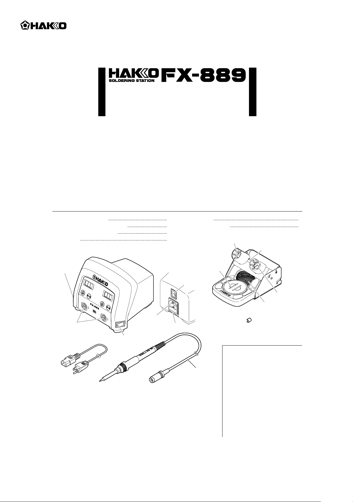
1. PACKING LIST AND PART NAMES
Color band
HAKKO FX-889 Station
HAKKO FX-8801 Soldering iron
HAKKO FH-801 Iron holder
Power cord
1
Instruction manual
1
1
1
Please check to make sure that all items listed
below are included in the package.
2
1
Iron receptacle
Rubber plate
Power switch
(for A.IRON)
Power switch
(Main)
Power cord
Receptacle
HAKKO
FX-889
Power switch
(for B.IRON)
Power cord
When using the HAKKO FX-8803 / FX-8804, please use
●
receptacle
Fuse
Cord assembly
HAKKO FX-8801
the applicable iron holder.
Each Hakko handpiece with the exception of the HAKKO FX-8801 /
●
FX-8805 has their own instruction manual. Please refer to this
manual for specifications and replacement parts.
Cleaning
sponge
HAKKO
FH-801 Iron holder
Color band
(×2)
※
Use this product with the
following models.
• HAKKO FX-8801
{Soldering iron (M)}
• HAKKO FX-8802
(Soldering iron N
• HAKKO FX-8803
(Soldering gun)
• HAKKO FX-8804
(SMD Hot tweezer)
• HAKKO FX-8805
{Soldering iron (L)}
Iron receptacle
Cleaning
wire
Type)
2
Page 2
2. SPECIFICATIONS
Power consumption 135W
● Station
Output
Temperature range
Temperature stability
Dimensions (W × H × D)
Weight (w/o cord)
* The temperature was measured using the FG-100 thermometer. * This product is protected against electrostatic discharge.
* Specifications and design are subject to change without notice.
AC26V
50 - 480℃ (120 - 899℉)
±1℃ (±1.8℉) at idle temperature
{When set to 200-480℃ (400-899℉)}
157(W) × 121(H) × 149(D) mm
(6.2 × 4.8 × 5.9 in.)
2.1 kg (4.6 lb.)
● HAKKO FX-8801 Soldering iron
Power consumption
Tip to ground resistance
Tip to ground potential
Heating element
Cord
Total length (w/o cord)
Weight (w/o cord)
AC26V 65W
< 2 Ω
< 2 mV
Ceramic heater
1.2 m (3.9 ft.)
217 mm (8.5 in.) with B tip
46 g (0.10 lb.) with B tip
■ Electrostatic Protection
This product includes such features as electrically conductive plastic parts and grounding of the unit
as measures to protect the device to be soldered from the effects of static electricity. Be sure to observe
the following instructions:
1. The plastic parts are not insulators, they are conductors. When making repairs or replacing parts,
take sufficient care not to expose live electrical parts or damage insulation materials.
2. Be sure to ground the unit during use.
3. WARNINGS, CAUTIONS AND NOTES
Warnings, cautions and notes are placed at critical points in this manual to direct the operator’s
attention to significant items. They are defined as follows:
WARNING: Failure to comply with a WARNING may result in serious injury or death.
CAUTION: Failure to comply with a CAUTION may result in injury to the operator, or damage to the
items involved.
WARNING
When power is ON, tip temperatures will be between 50 and 480℃. (120 to 899℉)
To avoid injury or damage to personnel and items in the work area, observe the
following:
● Do not touch the tip or the metal parts near the tip.
● Do not allow the tip to come close to, or touch, flammable materials.
● Inform others in the area that the unit is hot and should not be touched.
● Turn the power off when not in use, or left unattended.
● Turn the power off when changing parts or storing the HAKKO FX-889.
● This unit is for counter or workbench use only.
● This appliance can be used by children aged from 8 years and above and
persons with reduced physical, sensory or mental capabilities or lack of
experience and knowledge if they have been given supervision or instruction
concerning use of the appliance in safe way and understand the hazards
involved.
● Children shall not play with the appliance.
● Cleaning and user maintenance shall not be made by children without
supervision.
To prevent accidents or damage to the HAKKO FX-889, be sure to observe the following:
● Do not use the HAKKO FX-889 for applications other than soldering.
● Do not strike the iron against hard objects to remove excess solder. This will damage the iron.
● Do not modify the HAKKO FX-889.
● Use only genuine HAKKO replacement parts.
● Do not allow the HAKKO FX-889 to become wet, or use it with wet hands.
● Remove power and iron cords by holding the plug, not the wires.
● Be sure the work area is well ventilated. Soldering produces smoke.
● While using the HAKKO FX-889, don’t do anything which may cause bodily harm or physical damage.
1
Page 3
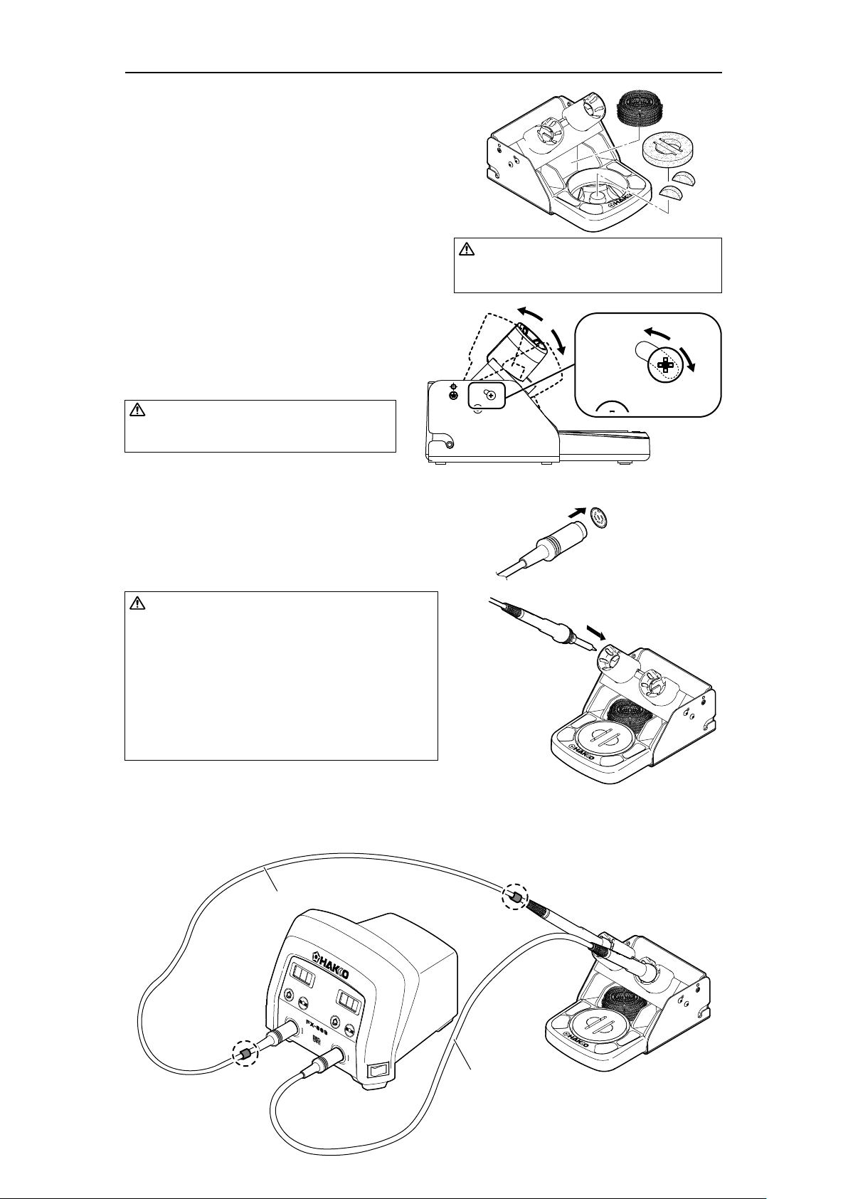
4. INITIAL SETUP
A. Setup the iron holder
(1) Cleaning Sponge
1. Fit the small sponge pieces into the hollows of the
iron holder base.
2. Add an appropriate amount of water into the iron
holder base. The small sponge will absorb water
and help keep the large sponge damp at all times.
3. Dampen the large sponge and place it on the iron
holder base.
(2) Cleaning Wire
Place it in the iron holder as shown on the right.
See “B. Using the cleaning wire” in section
“7. MAINTENANCE”.
The angle of the iron receptacles is adjustable by
changing the fastening position of the screws.
CAUTION
Increasing the angle of the iron receptacle will
cause an increase in the iron grip temperature.
B. Connect the iron to the station
1. Connect the cord assembly to the receptacle.
2. Place the iron into the iron holder.
3. Plug the power cord into an appropriate power
supply.
CAUTION
Be sure the sponge is moistened with water
before use to avoid damaging the tip.
Push on the plug until
it stops, making sure it is
securely connected.
To disconnect, hold the plug
and pull it out of the receptacle.
Receptacle
(2)
(1)
CAUTION
• Be sure to turn off the power before connecting or
disconnecting the cord assembly for the iron to and
from the receptacle to avoid damaging the circuit
board.
• Do not use any iron other than those listed in Section
1 of this manual. Doing so may result in inadequate
performance and / or possible damage to the unit.
• The unit is protected against electrostatic discharge
and must be grounded for full efficiency.
※
When using two soldering irons simultaneously
Attachment of the color bands to one of the soldering irons will help identify which soldering
iron is connected to receptacle “A.IRON” and “B.IRON”.
With color bands
Without color band
2
Page 4
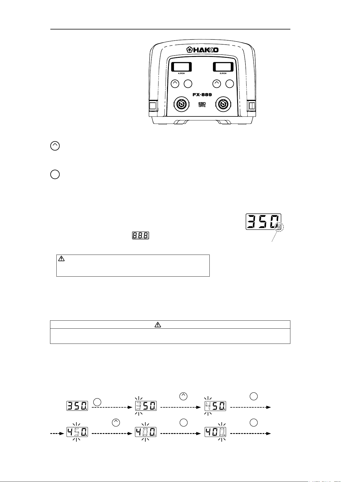
5. OPERATION
● Operation and indication
Switch and control button
ENTER
UP
ENTER
UP
The front panel of HAKKO FX-889 has two control buttons each for “A.IRON” and “B.IRON.”
– Use this button to select and change settings.
UP
• In the temperature preset mode, pressing this button will change the selected preset temperature
while the unit is in operation.
• Pressing and holding the button will start the adjustment mode.
ENTER
– Use this button to make and confirm selections.
• Pressing this button will display the current set temperature.
• Pressing and holding the button will start the temperature setting mode.
A. Operation
1. Turn on the power switch (main) located on the back.
2. Turn on either one of power switches located on each side depending
on which receptacle of “A.IRON” or “B.IRON” is used.
After turning on the power switch, will be displayed
for two seconds, and current temperature will be displayed.
When the display stabilizes, the LED heater lamp will begin to flash.
LED heater lamp
CAUTION
Place the iron in the iron holder when not in use. Turn the power off
when the HAKKO FX-889 is not in use for an extended period.
B. After use
Always clean the tip and coat it with fresh solder after use.
(Refer to “Tip Maintenance.”)
● Making Changes to Settings
CAUTION
If no buttons are pressed for at least one minute during the process of changing settings of the unit,
the system will exit and return to operating mode and display the current temperature.
A. Changing the set temperature
The temperature setting range is from 50 to 480℃. (from 120 to 899℉)
By default, the temperature is set to 350℃. (662℉)
Example : Changing from 350℃ to 400℃
Press and hold the
ENTER
button for at
least one second.
Press the button
five times.
UP
Press the button
once.
Press the button
once.
UP
ENTER
Press the button
once.
Press the button
once.
ENTER
ENTER
The desired temperature is saved to the system memory.
3
Heater control will begin after the new set temperature is displayed.
Page 5
B. The preset mode
The HAKKO FX-889 has a preset mode that will allow the unit to store up to 5 preset temperatures you
can change between instead of using the above normal mode.
Initial preset temperatures
P1: 250℃ (482℉), P2: 300℃ (572℉), P3: 350℃ (662℉), P4: 400℃ (752℉), P5: 450℃ (842℉)
The initial number of active presets is set to 5 at the factory.
The default selected preset is set to P3 at the factory.
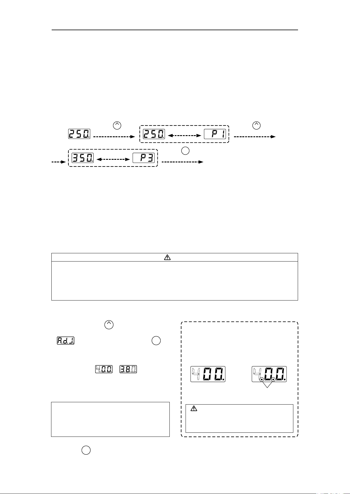
Example : Changing preset temperature from preset No.1 (250℃) to No.3 (350℃).
Press the button
once.
UP
Be displayed
alternately.
*Preset selection screen
Be displayed
alternately.
Press the button
once.
ENTER
Press the button
twice.
UP
Heater control will begin with new preset temperature.
The procedure for making changes to the preset temperatures is the same with “A. Changing the set
temperature” in 5. OPERATION. Enter the parameter setting to change the mode. (Please refer to [6.
PARAMETER SETTING])
C. Performing the temperature adjustment
When replacing the iron, heater or tip, a temperature adjustment may be required.
Use adjustment mode to perform the temperature adjustment.
CAUTION
• Enter the observed value in the adjustment mode after the tip temperature stabilizes.
• The maximum single adjustment that can be made is ±150℃ (270℉) relative to the set temperature.
If a larger adjustment is needed, make the first adjustment at the maximum value of 150℃ (270℉),
then repeat the adjustment process.
• When a new soldering iron is used or insertion position is changed from A.IRON to B.IRON (and vice
versa), temperature adjustment is always required.
Example : If the measured temperature is 380℃, and the set temperature is 400℃.
1. Press and hold the button for at least
two seconds.
● is displayed. When you press the
button, the display will move to the adjust mode.
UP
* How to distinguish between Temperature
Setting Mode and Adjustment Mode.
ENTER
The display differs in the temperature setting
and the adjustment mode.
In the Temperature
Setting Mode
2. Changing from to .
● The procedure for changing the value in
adjustment mode is the same as setting the
temperature in normal mode.
Please refer to Section 5 - OPERATION.
NOTE:
During adjustment mode, the hundreds digit will
accept values from 0 through 6 if the temperature
is set to display in ℃, or the values 0 through 9
if the temperature is set to display in ℉.
3. Press the button to exit the setting after
ENTER
CAUTION
Please be sure to confirm the status of the
identification lamps so that you do not enter
a value in the wrong mode.
Identification lamps are on
in the adjustment mode.
changing the values.
● The tip temperature will be adjusted accordingly.
In the Adjustment
Mode
4
Page 6
D. Restriction on setting changes (Password function)
It is possible to restrict certain setting changes to the unit.
There are three choices for the password setting. (The factory default is "0 : Open")
Move to the parameter setting mode
Move to the temperature setting mode
Move to the preset selection mode
Move to the adjust mode
0 : Open
○
○
○
○
1 : Partial
×
△
△
△
2 : Restricted
×
×
×
×
○ : You can make changes without entering a password.
△ : You can choose whether or not a password is needed to make changes.
× : A password is required to make changes.
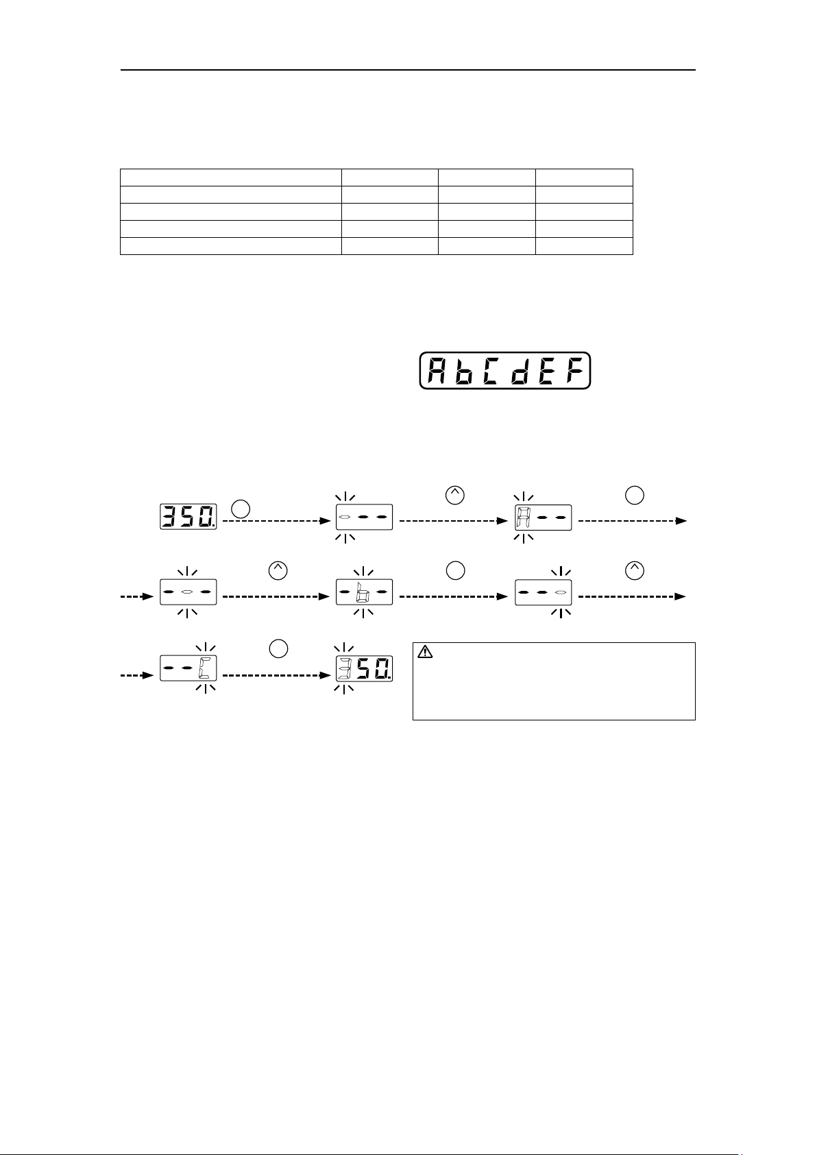
Select and input three letters for password
from six letters on the right.
The letters
for password
Example: The procedure for changing the set temperature when the unit is restricted by a password.
(Password is “AbC”)
Press and hold the
ENTER
button for at
least one second.
Press the button
twice.
UP
Press the button
once.
Press the button
once.
UP
ENTER
Press the button
once.
Press the button
three times.
ENTER
UP
Press the button
once.
ENTER
CAUTION
• If the password you entered is incorrect, the display will
show three dashes for you to re-enter the password.
• If you enter the password incorrectly twice in a row, the
display will return to the previous screen.
The unit will move to the change setting screen for each mode after entering the password.
Please change the setting for each mode according to the procedure.
Enter the parameter setting to change the mode. (Please refer to [6. PARAMETER SETTING])
5
Page 7

6. PARAMETER SETTING
The HAKKO FX-889 has the following parameters.
1
※
2
Parameter No.
※
2
Value
°C / °F
54 – 270°F (30 – 150°C)
0: The normal mode / 1: The preset mode
(2 pcs.) – (5 pcs.)
0: Open / 1: Partial / 2: Restricted
: ○
: ○
: ○
※
4
/ : ×
※
4
/ : ×
※
4
/ : ×
※
4
※
4
※
4
Select three letters
Parameter name
℃/F selection
Low temperature error setting
Setting mode selection
The number of preset
※
Password setting
Temperature setting mode
Preset selection mode
※
Adjust mode
Password
※
1 It is displayed only when “1: Preset mode” is selected in the setting mode.
※
2 It is displayed only when “1: Custom” is selected in the password setting.
※
3 It is displayed only when either “1: Custom” or “2: valid” is selected in the password setting.
※
4 ○: Password not required ×: Password required
2
※
3
● Changing Parameter Setting
The HAKKO FX-889 has four parameters. Parameter settings can be set for A. IRON and B. IRON
respectively.
Initial value
℃
150°C
0
0
-
● : ℃ or ℉ temperature display seletion
The displayed temperature can be switched between Celsius and Fahrenheit.
● : Low temperature error setting
If the sensor temperature goes below the low-limit temperature although heating element is on, an error
will be displayed.
● : Setting mode selection
Temperature setting can be switched between the normal mode and the preset mode.
If selecting the preset mode, you will be asked for the number of preset you required.
Press the button to set the number.
UP
● : Password setting
Select “Open”, “Partial” or “Restricted” for password setting.If selecting the Restricted, perform the
setting for password. If selecting the partial, choose whether or not the password function is needed
when moving to the temperature setting mode, the preset mode and the adjust mode and set the
password.
● Parameter entering mode
1. Turn off the power switch.
2. Turn on the power switch while pressing the button.
UP
3. When the display shows , the station is in parameter entering mode.
6
Page 8

A. ℃ or ℉ temperature display selection
1. Either or will be displayed if you press the button when is displayed.
ENTER
2. and will be switched alternately If you press the button.
3. The display will return to if you press the button after selecting.
ENTER
UP
B. Low temperature error setting
1. Press the button to change the display to .
2. The low-limit temperature will be displayed if you press the button. Enter the value in the same
UP
ENTER
manner as described in the normal mode [5. OPERATION ●The normal mode]
3. The display will return to if you press the button after setting.
ENTER
C. Setting mode selection
1. Press the button to change the display to .
2. If you press the button, the display will move to the setting mode selection screen. If you press
the button, (The normal mode) and (The preset mode) will be switched alternately.
3. The display will return to if you press the button after selecting.
UP
ENTER
UP
ENTER
※
※
If you select the preset mode, the display will move to the preset selection screen.
4. The number of active preset will be displayed If you press the button at 3.
ENTER
(Example : If the number is three, is displayed.)
5. Press the button to change the value and select the number of active preset you required.
UP
The unit will accept values from 2 through 5.
6. The display will return to if you press the button after selecting.
ENTER
7
Page 9

D. Password setting
1. Press the button to change the display to .
2. If you press the button, the display will move to the setting mode selection screen.
If you press the button, (Open), (Partial) and (Restricted) will be switched
UP
ENTER
UP
alternately.
3. If you press the button after selecting, the display will return to . ※1, 2
※
1 The display will move to the following selection screen if you select (Partial).
4. If you press the button at 3, you will be asked whether or not the password function is needed
ENTER
ENTER
when moving to the temperature setting mode.
5. Either (without password) or (with password) will be displayed if you press the
UP
button.
6. If you press the button after selecting, you will be asked whether or not the password function is
ENTER
needed when moving to the preset selection mode.
7. Either (without password) or (with password) will be displayed if you press the
UP
button.
8. If you press the button after selecting, you will be asked whether or not the password function is
ENTER
needed when moving to the adjust mode.
9. Either (without password) or (with password) will be displayed if you press the
UP
button.
10. If you press the button after selecting, the display will move to password setting screen.
※
2 If you select (Restricted), the display will move to the following password setting
ENTER
screen.
If you select (Partial), the display will move to the following the password setting
screen after selecting ※1.
11. The hundreds digits in the display will begin to flash. It indicates that you can enter the value.
Press the button to enter the letter you required.
12. The tens digits in the display will begin to flash if you press the button after entering.
UP
ENTER
Use the same procedure to enter the letters for tens and units digit.
13. The display will return to if you press the button after entering the units digit.
After changing parameters, press and hold the button down for at least two seconds until is
displayed. At this time, you can switch between and by pressing the button. Select
ENTER
ENTER
UP
if you are finished making changes or if you need to go back and make more changes. Press the
ENTER
button to confirm you selection.
Changes will not be completed until is displayed and you press the button.
ENTER
Please note that no changes will be made if you turn off the power while making changes.
8
Page 10

7. MAINTENANCE
Performing proper and periodic maintenance extends product life. Efficient soldering depends upon the
temperature, quality and quantity of the solder and flux.
Apply the following service procedure as dictated by the conditions of usage.
WARNING
Since the soldering iron can reach a very high temperature, please work carefully.
Except the case especially indicated, always turn the power switch OFF and disconnect the
power plug before performing any maintenance procedure.
Tip Maintenance
1. Set the temperature to 250℃ (482℉).
2. When the temperature stabilizes, clean the tip with the cleaning sponge and check the condition of the tip.
3. If the solder plated part of the tip is covered with black oxide, apply fresh solder containing flux, and clean
the tip again. Repeat until all the oxide is removed, then coat the tip with fresh solder.
4. If the tip is deformed or heavily eroded, replace it with a new one.
CAUTION
Do not file the tip in an attempt to remove the black oxide.
● Cleaning the tip using the iron holder
A. Using the cleaning sponge
Use the cleaning sponge that comes with the product to
clean the tip. It offers wide-ranging uses, from simple
C
B
A
● Cleaning of solder fragments
HAKKO FH-801 iron holder has a removable holder base. When solder debris
accumulates, remove the holder base, and properly dispose of the contents.
removal of excess solder to complete elimination of matter
occurring as a result of oxidization.
B. Using the cleaning wire
Material that is not removed easily with the cleaning
sponge can likely be removed using the cleaning wire.
C. Using the rubber plate
Wipe the iron lightly across the rubber ring to remove
excess solder from the tip.
Holder base
Remove
9
Page 11

8. CHECKING PROCEDURE
Disconnect the plug of the cord assembly and
measure the resistance value between the ping
of the connecting plug as follows.
If the values of “a” and “b” are outside the value
in the table, replace the heating element
(sensor) and/or cord assembly.
If the value of “c” is over the value in the table,
remove the oxidization film by lightly rubbing with
sand-paper or steel wool the points shown in the
drawing on the right.
A. Broken Heating Element/Sensor
● Disassembling
a. Between pins 4 & 5
(Heating Element)
b. Between pins 1 & 2 (sensor)
c. Between pin 3 & Tip
2.5 – 3.5 Ω
(at time of room temperature)
43 – 58 Ω
2 Ω or less
Buff lightly.
1. Turn the nut ① counterclockwise and remove the
tip enclosure ② and the tip ③.
2. Turn the nipple ④ counterclockwise and remove it
from the iron.
3. Pull both the heaing element ⑥ and the cord
assembly ⑦ out of the handle ⑧. (Toward the tip of
the iron).
4. Pull the grounding spring ⑤ out of the sleeve of the
terminal ⑨.
Heating element
resistance (red)
Sensor resistance
(blue)
* Measure when the heating element is at room
temperature.
1. Heating element resistance (red) 2.5 – 3.5 Ω
2. Sensor resistance (blue) 43 – 58 Ω
If the resistance value is not normal, replace the
heating element. (Refer to the instructions included
with the replacement part.)
After replacement
1. Measure the resistance between pins 4 and 1, 4 and 2, 5 and 1, and 5 and 2. If it is not ∞, the heating
element and sensor are touching. This will damage the circuit board.
2. Measure the resitance “a,” “b,” and “c” to confirm that the leads are not twisted and that the grounding
spring is properly connected.
B. Broken Cord Assembly
There are two methods of testing the cord
assembly.
1. Turn the unit ON and set the temperature control
knob to 480℃. Then bend the iron cord at various
locations along its length, including in the strain
relief area. The cord assembly needs to be
replaced if S-E is displayed or although the LED
heater lamp flashes, the tip temperature doesn’t
rise.
CAUTION
The power lamp starts to flash when the
temperature reaches 480°C (880°F) regardless
of the condition of the cord.
2. Check the resistance between the plug pin and the
terminal lead.
Pin 1: Red Pin 2: Blue Pin 3: Green Pin 4: White
Pin 5: Black
Resistance: 0 Ω.
If it is higher than 0 Ω or is ∞, the cord should be
replaced.
10
Page 12

9. ERROR MESSAGES
● Sensor Error
● Low-temperature alarm
tolerance error
EXAMPLE:
350°C (400°C – 50°C)
Set temperature
650°F (750°F – 100°F)
Set temperature Low-temperature
Low-temperature
alarm tolerance
OR
alarm tolerance
When there is the possibility that a failure has occurred in the sensor or
heater (including the sensor circuit), is displayed and the power is
shut down.
CAUTION
The sensor error also occurs if the tip is not inserted properly.
If the sensor temperature falls below the difference between the current
temperature setting and the low-temperature alarm tolerance, is
displayed and the warning buzzer sounds. When the tip temperature
rises to a value within the set tolerance, the buzzer will stop sounding.
EXAMPLE:
Assume that the temperature setting is 400°C/750°F and the
tolerance 50°C/100°F. If the temperature continues to decrease and
finally falls below the value indicated below while the heating element
is on, the displayed value starts blinking to indicate that the tip
temperature has dropped.
11
Page 13

10. TROUBLE SHOOTING GUIDE
WARNING
Before checking the inside of the HAKKO FX-889 or replacing parts, be sure to disconnect the power plug.
● Nothing happens when the power
switch is turned on.
● The heater lamp lights up but the tip
does not heat up.
● The Heater-error is displayed.
● The tip heats up intermittently.
CHECK : Is the power cord and/or connecting plug disconnected?
ACTION : Connect it.
CHECK : Is the fuse blown?
ACTION : Determine why the fue blew and eliminate the cause, then
replace the fuse.
a. Is the inside of the iron short-circuited?
b. Is the grounding spring touching the heating element?
c. Is the heating element lead twisted and short-circuited?
Try replacing the fuse even if the cause cannot be identified.
If it still blows, return the product for repair.
CHECK : Is the cord assembly broken? Is the heating element/
sensor broken?
ACTION : If the cord assembly is broken, replace the HAKKO FX-8801.
If the heating element / sensor is broken, replace the heating
element.
a. Between pins 4 & 5 (Heating Element) 2.5 - 3.5 Ω (at time of room temperature)
b.
Between pins 1 & 2 (sensor) 43 - 58 Ω
c.
Between pin 3 & Tip 2 Ω or less
CHECK : Is the heater broken?
ACTION : If the heater is broken, replace the heating element.
CHECK :
ACTION : Increase the setting value.
CHECK : Is the cord assembly broken?
ACTION : If the cord assembly is broken, replace the HAKKO FX-8801.
Is the setting value for the low-temperature alarm tolerance too low?
● Solder does not wet to the tip.
● The tip temperature is too low.
● The tip can not be pulled off.
● The tip doesn’t hold the desired
temperature.
CHECK : Is the tip temperature too high?
ACTION : Set an appropriate temperature.
CHECK : Is the tip coated with black oxide?
ACTION : Remove the black oxide. (Refer to “Tip Maintenance.”)
CHECK : Is the tip coated with black oxide?
ACTION : Remove the black oxide. (Refer to “Tip Maintenance.”)
CHECK : Is the iron temperature adjusted correctly?
ACTION : Perform the temperature adjustment.
CHECK : Is the tip seized? Is the tip swollen because of deterioration?
ACTION : Replace the tip and the heating element.
CHECK : Is the iron temperature adjusted correctly?
ACTION : Perform the temperature adjustment.
12
Page 14

11. PARTS LIST (Station)
②
SEMS screw
M4×8 (4) P3
⑨
⑥
Tapping screw
P tight
DN4×10 (4)
External tooth lock washer
DN4 (1)
⑩
SEMS screw
M4×8 (2) P2
⑦
External tooth
lock washer
DN4 (1)
⑧
Tapping screw
P tight
DN3×6 (8)
External tooth
lock washer
DN4 (1)
④
③
13
①
⑥
⑤
⑤
● HAKKO FX-889 station
Item No.
1
2
3
4
5
6
7
8
9
Part No.
B5110
B5 111
B3736
B5112
B5113
B5114
B3463
B5123
B5279
B5280
B2468
B5124
B5125
Part Name
Front panel
Cover
P.W.B.
Transformer
Transformer
Transformer
Receptacle
Switch
Inlet/100 - 120V
Inlet/200 - 240V
Fuse
Fuse
Color band
⑥
Specifications
for temperature control
100 - 110V
120V
220 - 240V
with varistor
with varistor
100 - 120V
220 - 240V
set of 2
③
Item No.
10
Part No.
B2419
B2421
B2422
B2424
B2425
B2436
B2426
B3508
B3550
Tapping screw
P tight
DN4×10 (4)
Part Name
Power cord, 3-wire cord
& American plug
Power cord, 3-wire cord
but no plug
Power cord, 3-wire cord
& BS plug
Power cord, 3-wire cord
& European plug CE
Power cord, 3-wire cord
& BS plug CE
Power cord, 3-wire cord
& Chinese plug
Power cord, 3-wire cord
& Australian plug
Power cord, 3-wire cord
& American plug (B)
Power cord, 3-wire cord
& SI plug
Specifications
USA
220-240V
India
220VKTL,230VCE
230VCE,U.K
China
Page 15

12. PARTS LIST (Soldering iron)
●
Item No.
1 ~ 11
●
Item No.
HAKKO FX-8801 Soldering iron
Part No.
FX8801-01
Part Name
HAKKO FX-8801
Soldering iron parts
Part No.
B1785
1
B3469
2
3
B2022
4
B2032
5
A1560
6
B2028
7
B3470
8
B3471
9
B3467
10
B3468
11
Part Name
Nut
Tip enclosure
Tip
Nipple
Grounding spring
Heating element
Terminal board
Handle
Handle cover
Cord bushing
Cord assembly
See “13. TIP STYLES”
26V-65W
with cord stopper
with handle cover
Specifications
Specifications
②
①
Optional Parts
●
Item No.
Part No.
1
B5122
Part Name
Tip enclosure assembly
Specifications
* If you use the capacious tip T19, change to above tip
enclosure
assembly
. Please see the tip styles and tip shape
for T19 from the following URL.
⇨ https://www.hakko.com
● HAKKO FH-801
Part No.
FH801-81
● Iron holder parts
Part No.
Item No.
1
A1519
2
A1561
Part Name
HAKKO FH-801
Part Name
Cleaning sponge
Cleaning wire
Specifications
with cleaning sponge,
cleaning wire
Specifications
14
Page 16

13. TIP STYLES
T18-B Shape-B T18-SB Shape-SB T18-BR02 Shape-0.2BR T18-BL Shape-BL T18-C05 Shape-0.5C
R0.5
(0.020)
14.5
(0.57)
T18-C08 Shape-0.8C T18-C1 Shape-1C
Φ0.8
(0.031)
0.8
45°
(0.031)
T18-C3 Shape-3C
T18-CF3*
3.2
(0.13)
15.5
(0.61)
Φ3
(0.12)
45°
14.5
(0.57)
4.2
(0.17)
R0.2
(0.008)
(0.52)
T18-CF1*
Φ1
(0.04)
60°
1
(0.04)
13.5
(0.53)
T18-C4 Shape-4C
T18-CF4*
Φ4
(0.16)
45°
14.5
(0.57)
13.2
4
(0.16)
30°
R0.2
10.5
(0.008)
(0.41)
T18-CF15* Shape-1.5C T18-C2 Shape-2C
Φ1.5
(0.06)
60°
1.6
(0.06)
13.5
(0.53)
T18-C5 Shape-5C T18-K Shape-K T18-D08 Shape-0.8D
Φ5
(0.20)
5
45°
(0.20)
14.5
(0.57)
R0.2
(0.008)
T18-CF2*
2.1
(0.08)
(0.08)
Φ0.5
(0.020)
0.5
45°
22.5
(0.89)
(0.020)
13.5
(0.53)
T18-CSF25* Shape-2.5CS
Φ2
(0.08)
45°
14.5
(0.57)
Φ5
(0.20)
45°
2
14
(0.55)
2.5
(0.10)
0.6
(0.024)
Φ0.8
Φ2.5
(0.031)
(0.10)
45°
(0.39)
14.5
(0.57)
10
T18-D12 Shape-1.2D T18-D16 Shape-1.6D T18-D24 Shape-2.4D T18-D32 Shape-3.2D T18-DL12 Shape-1.2DL
Φ1.2
(0.05)
0.7 14.5
(0.028)
(0.57)
Φ1.6
(0.06)
0.5 14.5
(0.020) (0.57)
Φ2.4
(0.09)
0.5 14.5
(0.020)
(0.57)
Φ3.2
(0.13)
14.5
0.5
(0.57)(0.020)
0.7
(0.028)
Φ1.2
(0.05)
22.5
(0.89)
T18-DL2 Shape-2DL T18-DL32 Shape-3.2DL T18-S3 Shape-S3 T18-S4 Shape-S4 T18-S6 Shape-S6
(0.04)
Φ2
(0.08)
1
22.5
(0.89)
(0.04)
Φ3.2
(0.13)
1
22.5
(0.89)
(0.04)
Φ5.2
(0.20)
1
18
(0.71)
R0.125
(0.005)
14.5
(0.57)
Φ1.3
(0.05)
60°
1.7
(0.07)
16.5
(0.65)
T18-S9 Shape-S9 T18-I Shape-I
R0.2
(0.008)
14.5
(0.57)
* Tinned on the soldering surface only.
● Use only genuine HAKKO soldering iron tips. Replacement tips
for the HAKKO FX-8801 are designated the T18 series.
0.4
(0.016)
Φ1.2
(0.05)
15.5
(0.61)
15
Page 17

14. WIRING DIAGRAM
Ground(Chassis) Ground(Chassis)
Receptacle
1
2
P.W.B.
Black
5
Black
4
3
Green/Yellow
Switch
Black
Red
H1H226V 0V
SE1
SE2
Red
White
White
White
White
Receptacle
1
2
P.W.B.
Black
5
Black
4
3
Green/Yellow
Switch
Black
Ground(Chassis)
0V26VH2H1
Black
Red
Red
Black
Transformer
SE2
SE1
Red
Green/Yellow
White
Varistor
Black
Power receptacle
Main power-supply
switch
16
Page 18

※各言語(日本語、英語、中国語、フランス語、ドイツ語、韓国語)の取扱説明書は以下の URL、
HAKKODocumentPortal からダウンロードしてご覧いただけます。
(商品によっては設定の無い言語がありますが、ご了承ください。)
* 各國語言(日語、英語、中文、法語、德語、韓語)的使用説明書可以通過以下网站的 HAKKO
DocumentPortal下載參閲。
(有一部分的產品沒有設定外語對應、請見諒)
* Instruction manual in the language of Japanese, English, Chinese, French, German, and Korean
can be downloaded from the HAKKO Document Portal.
(Please note that some languages may not be available depending on the product.)
https://doc.hakko.com
HEAD OFFICE
4-5, Shiokusa 2-chome, Naniwa-ku, Osaka 556-0024 JAPAN
TEL: +81-6-6561-3225 FAX: +81-6-6561-8466
https:// www.hakko.com E-mail: sales@hakko.com
OVERSEAS AFFILIATES
U.S.A.: AMERICAN HAKKO PRODUCTS, INC.
TEL: (661) 294-0090 FAX: (661) 294-0096
Toll Free (800) 88-HAKKO
4 2 5 5 6
https:// www.HakkoUSA.com E-mail: Support@HakkoUSA.com
HONG KONG: HAKKO DEVELOPMENT CO., LTD.
TEL: 2811-5588 FAX: 2590-0217
https:// www.hakko.com.cn E-mail: info@hakko.com.hk
SINGAPORE: HAKKO PRODUCTS PTE., LTD.
TEL: 6748-2277 FAX: 6744-0033
https:// www.hakko.com.sg E-mail: sales@hakko.com.sg
Please access the web address below for other distributors.
https://www.hakko.com
© 2016-2020 HAKKO Corporation. All Rights Reserved.
MA02818XZ200326
2020.3
 Loading...