

Page 1
Instruction Manual
Thank you for purchasing the HAKKO FX-888D soldering station.
Please read this manual before operating the HAKKO FX-888D.
Keep this manual readily accessible for reference.
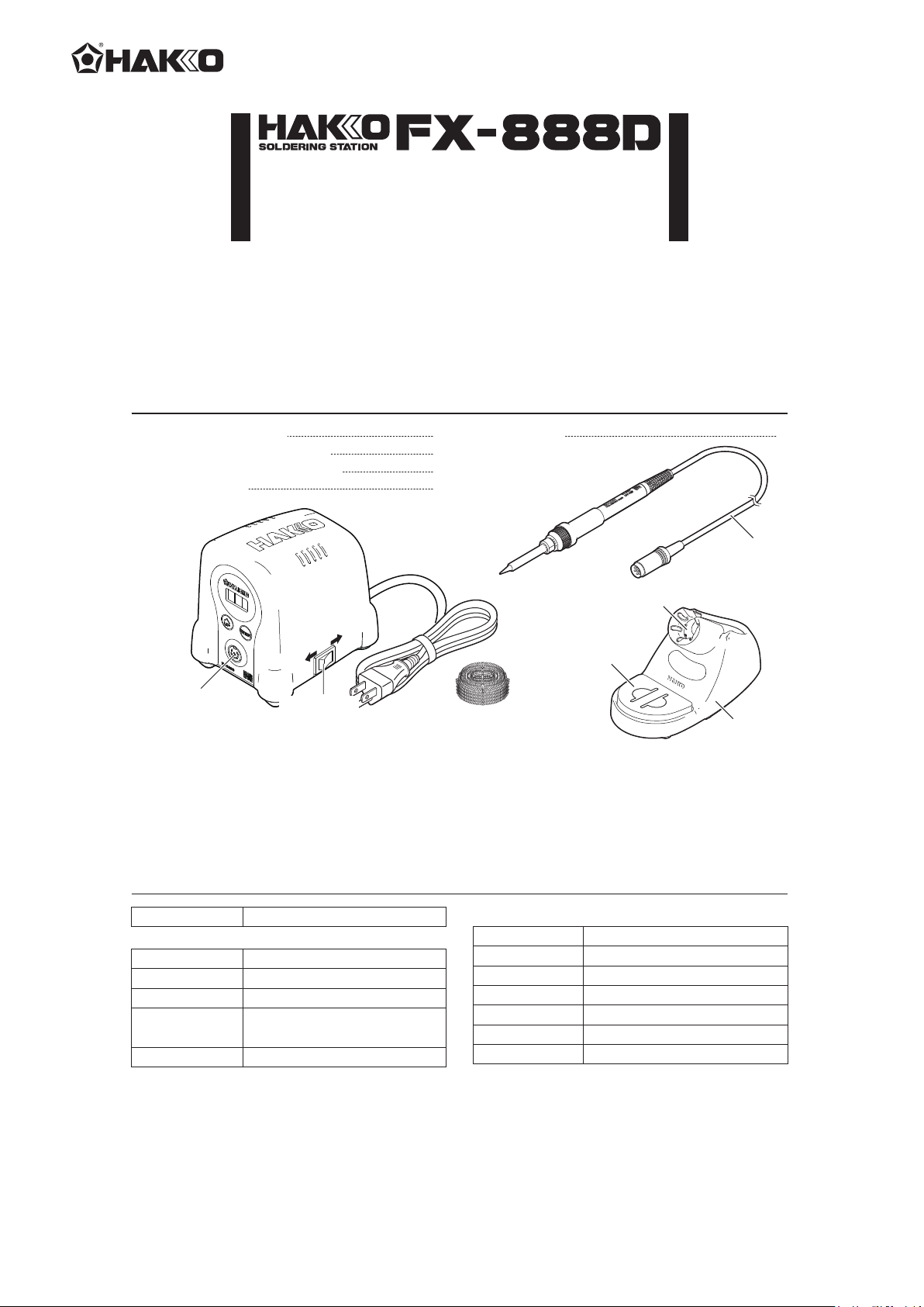
1. PACKING LIST AND PART NAMES
Cleaning wireHAKKO FX-888D Station
1
HAKKO FX-8801 Soldering iron
Iron holder (with cleaning sponge)
Instruction Manual
OFFON
Receptacle
Power switch
HAKKO FX-888D Station
1
1
1
Cleaning wire
Please check to make sure that all items listed
below are included in the package.
HAKKO FX-8801
Iron receptacle
Cleaning sponge
Iron holder
Cord assembly
Iron holder
base
*HAKKO FX-8802 / FX-8803 / FX-8804 (not included) can be connected to HAKKO FX-888D station.
*When using the HAKKO FX-8802/FX-8803/FX-8804, please use it with the applicable iron holder.
1
2. SPECIFICATIONS
Power consumption 70W
● Station
Output voltage
Temperature range
Temperature stability
Dimensions (W × H × D)
Weight (w/o cord)
* The temperature was measured using the FG-100 thermometer. * This product is protected against electrostatic discharge.
* Specifications and design are subject to charge without notice.
AC 26V
400 - 899℉ (200 - 480℃)
±1.8℉ (±1℃) at idle temperature
3.9(W) × 4.7(H) × 4.7(D) in.
(100 × 120 × 120 mm)
2.6 lb. (1.2kg)
■ Electrostatic Protection
This product includes such features as electrically conductive plastic parts and grounding of the unit
as measures to protect the device to be soldered from the effects of static electricity. Be sure to observe
the following instructions:
1. The plastic parts are not insulators, they are conductors. When making repairs or replacing
parts, take sufficient care not to expose live electrical parts or damage insulation materials.
2. Be sure to ground the unit during use.
● HAKKO FX-8801 Soldering iron
Power consumption
Tip to ground resistance
Tip to ground potential
Heating element
Cord length
Total length (w/o cord)
Weight (w/o cord)
65W (26V)
< 2 Ω
< 2 mV
Ceramic heater
3.9 ft. (1.2m)
8.5 in. (217mm) with 1.6D tip
0.10 lb. (46g / 1.62 oz.) with 1.6D tip
Page 2
3. WARNINGS, CAUTIONS AND NOTES
Warnings, cautions and notes are placed at critical points in this manual to direct the operator’s
attention to significant items. They are defined as follows:
Failure to comply with a WARNING may result in serious injury or death.WARNING:
CAUTION :
Failure to comply with a CAUTION may result in injury to the operator, or damage to the
items involved. Two examples are given below.
WARNING
When power is ON, tip temperatures will be between 400 to 899℉. (200 and 480℃) To avoid injury or
damage to personnel and items in the work area, observe the following:
● Do not touch the tip or the metal parts near the tip.
● Do not allow the tip to come close to, or touch, flammable materials.
● Inform others in the area that the unit is hot and should not be touched.
● Turn the power off when not in use, or left unattended.
● Turn the power off when changing parts or storing the HAKKO FX-888D.
● This appliance is not intended for use by persons (including children) with reduced physical, sensory or
mental capabilities, or lack of experience and knowledge, unless they have been given supervision or
instruction concerning use of the appliance by a person responsible for their safety.
● Children should be supervised to ensure that they do not play with the appliance.
● If the power cord is damaged, it must be replaced by the manufacturer, its service agent or similarly
qualified person in order to avoid personal injury or damage to the unit.
● The unit is for a counter or workbench use only.
● To prevent accidents or damage to the HAKKO FX-888D, be sure to observe the following:
● Do not use the HAKKO FX-888D for applications other than soldering.
● Do not strike the iron against hard objects to remove excess solder. This will damage the iron.
● Do not modify the HAKKO FX-888D.
● Use only genuine Hakko replacement parts.
● Do not allow the HAKKO FX-888D to become wet, or use it with wet hands.
● Remove power and iron cords by holding the plug. not the wires.
● Be sure the work area is well ventilated. Soldering produces smoke.
● While using the HAKKO FX-888D, don’t do anything which may cause bodily harm or physical damage.
4.INITIAL SETUP
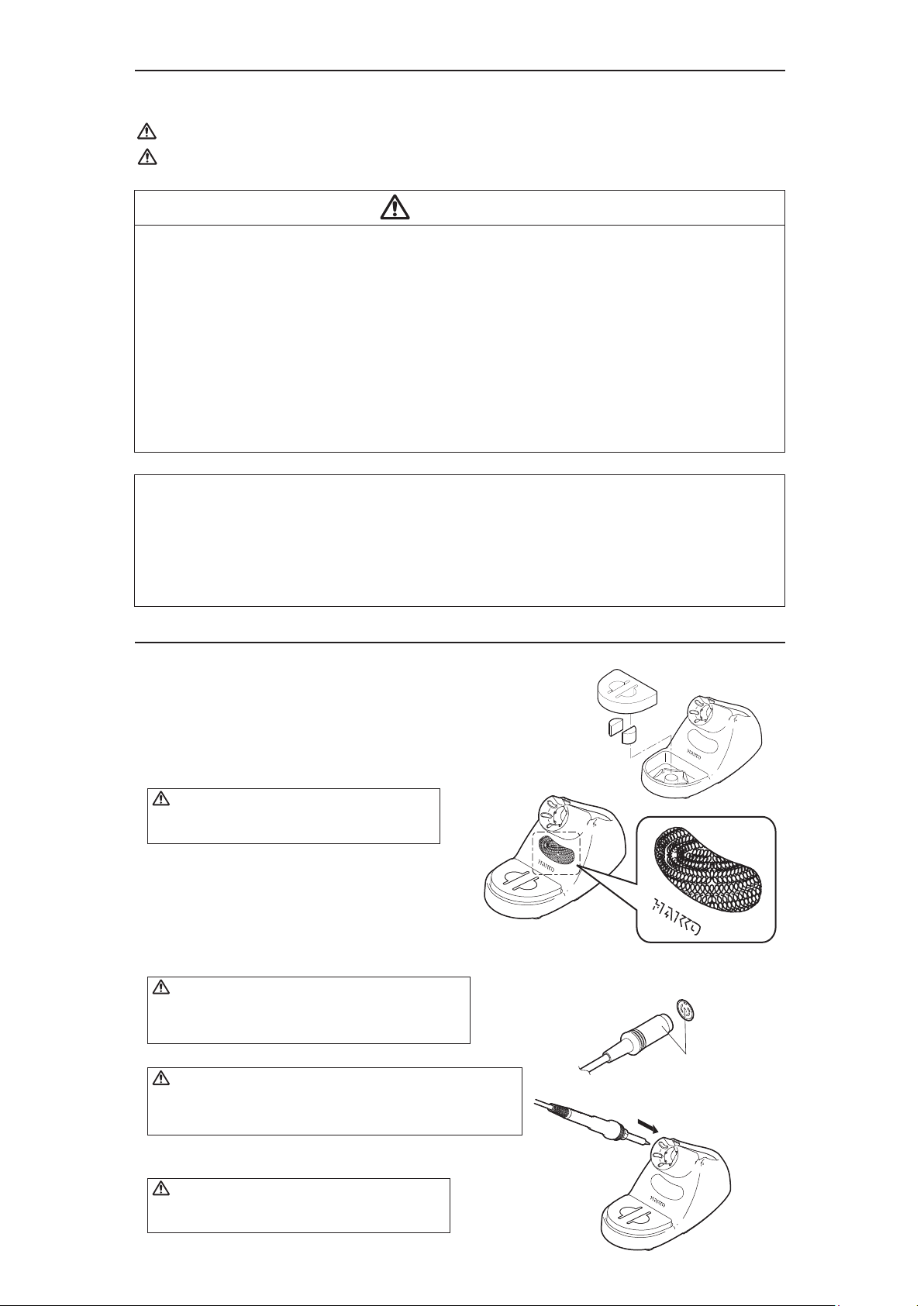
A. Setup the iron holder
1. Fit the small sponge pieces into the hollows of the iron holder base.
2. Add an appropriate amount of water into the iron
holder base. The small sponge will absorb water
and help keep the large sponge damp at all times.
3. Dampen the large sponge and place it on the
iron holder base.
CAUTION
Be sure the sponge is moistened with water
before use to avoid damaging the tip.
*When using a Cleaning Wire
Place it in the iron holder as shown on the right. See
"2.Using a Cleaning Wire" in section "7. MAINTENANCE"
B. Connect the iron to the station
CAUTION
Be sure to turn off the power before connecting or
disconnecting the cord assembly for the iron to and
from the receptacle to avoid damaging the circuit board.
1. Connect the cord assembly to the receptacle.
CAUTION
Do not use any iron other than those listed in Section 1 of this
manual. Doing so may result in inadequate performance and / or
possible damage to the unit.
2. Place the iron into the iron holder.
3. Plug the power cord into an appropriate power supply.
Small sponge
pieces
Push on the plug until
it stops, making sure it is
securely connected.
Large sponge
Receptacle
To disconnect, hold the plug
and pull it out of the receptacle.
CAUTION
The unit is protected against electrostatic discharge
and must be grounded for full efficiency.
Page 3
5.OPERATION
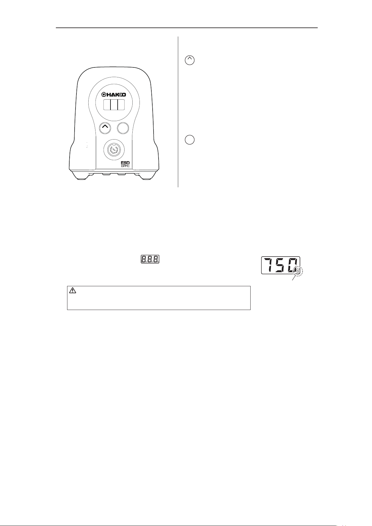
● Operation and indication
Switch and control button
ENTER
UP
FX-888D
The front panel for the FX-888D has the following two
control buttons.
−Use this button to select and change settings.
UP
In the temperature preset mode,
pressing this button will change the selected
preset temperature while the unit is in operation.
Pressing and holding the button will start
the adjustment mode.
ENTER
−Use this button to make and confirm selections.
Pressing this button will display the current set
temperature.
Pressing and holding the button will start
the temperature setting mode.
A. Turn on the power switch
After turning on the power switch, will be displayed
for two seconds, and current temperature will be displayed.
When the display stabilizes, the LED heater lamp will begin to flash.
CAUTION
Place the iron in the iron holder when not in use.
Turn the power off when the FX-888D is not in use for an extended period.
B. After use
Always clean the tip and coat it with fresh solder after use.
Heater lamp
Page 4
■ Making Changes to Settings
CAUTION
If no buttons are pressed for at least one minute during the process of changing settings of the unit,
the system will exit and return to operating mode and display the current temperature.
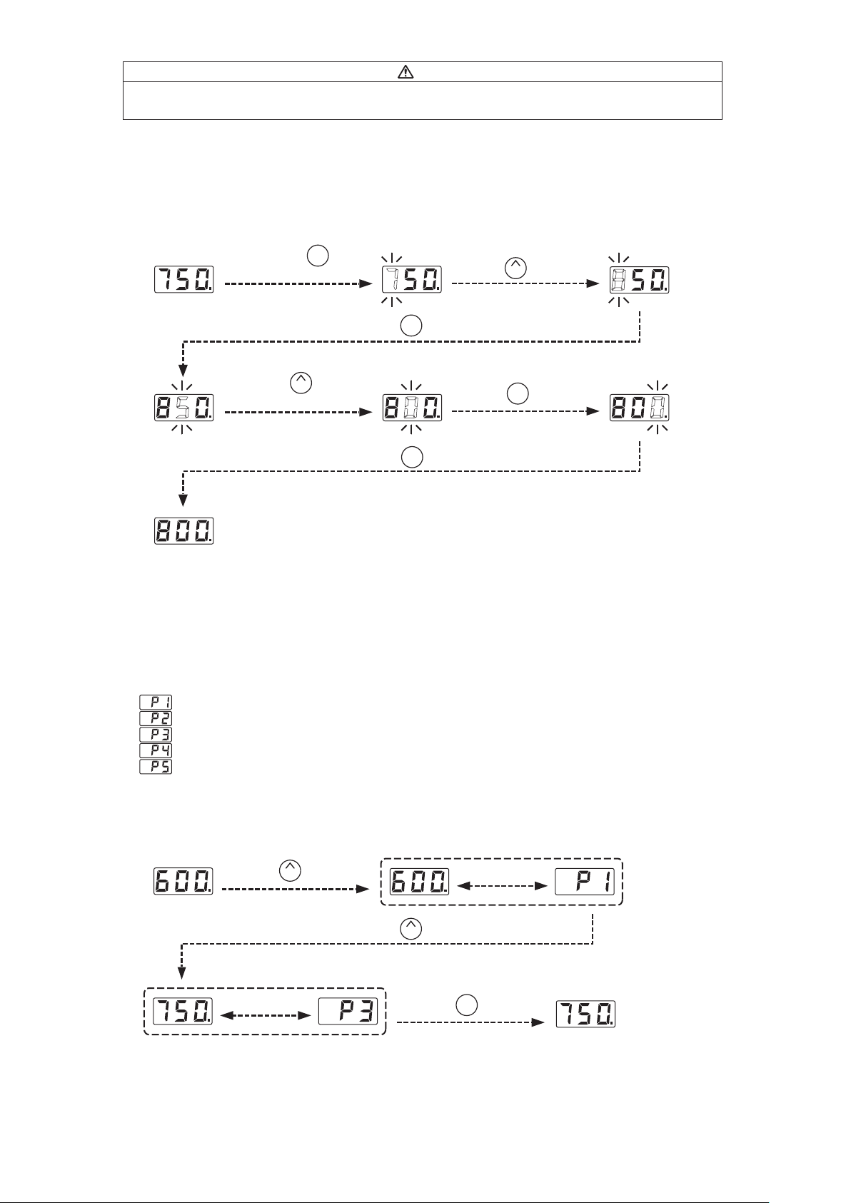
● Changing the set temperature
There are two ways to change the setting temperature : normal mode or preset mode.
The temperature setting range is from 400 to 899℉. (from 200 to 480℃)
By default, the temperature is set to 750℉. (399℃)
● The normal mode
Example : Changing from 750℉ to 800℉
Hold down the button
for at least one second.
ENTER
Press the button once.
UP
ENTER
ENTER
Press the button once.
ENTER
Press the button
UP
five times.
Press the button once.
Press the button once.
The desired temperature is saved to the system memory.
Heater control will begin after the new set temperature is displayed.
● The preset mode
The FX-888D has a preset mode that will allow the unit to store up to 5 preset temperatures you can change
between instead of using the above normal mode.
Initial preset temperatures
: 600℉ (316℃)
: 700℉ (371℃)
: 750℉ (399℃)
: 800℉ (427℃)
: 850℉ (454℃)
The initial number of active presets is set to 5 at the factory.
The default selected preset is set to P3 at the factory.
Example : Changing preset temperature from preset No.1(600℃) to No.3(750℃).
Press the button once.
Be displayed
UP
Press the button twice.
UP
Press the button once.
Be displayed
alternately.
ENTER
*Preset
selection
screen
alternately.
Heater control will begin with new preset temperature.
The procedure for making changes to the preset temperatures is the same as changing the set temperature
in normal mode.
Page 5
5. OPERATION
● Performing the temperature adjustment
When replacing the iron, heater or tip, a temperature adjustment may be required.
Use Adjustment Mode to perform the temperature adjustment.
CAUTION
• Enter the observed value in the adjustment mode after the tip temperature stabilizes.
• The maximum single adjustment that can be made is ±270℉ (150℃) relative to the set temperature.
If a larger adjustment is needed, make the first adjustment at the maximum value of 270℉ (150℃),
then repeat the adjustment process.
Example : If the measured temperature is 760℉,
and the set temperature is 800℉.
1. Press and hold the button down
for at least two seconds.
● The hundreds digits in the display will begin
to flash when shifting to the adjustment mode.
It indicates that you can enter the value.
2. Changing from to
● The procedure for changing the value in
adjustment mode is the same as setting
the temperature in normal mode.
Please refer to Section 5 - OPERATION.
NOTE :
During adjustment mode, the hundreds digit will
accept values from 0 through 6 if the temperature
is set to display in ℃, or the values 0 through 9
if the temperature is set to display in ℉.
UP
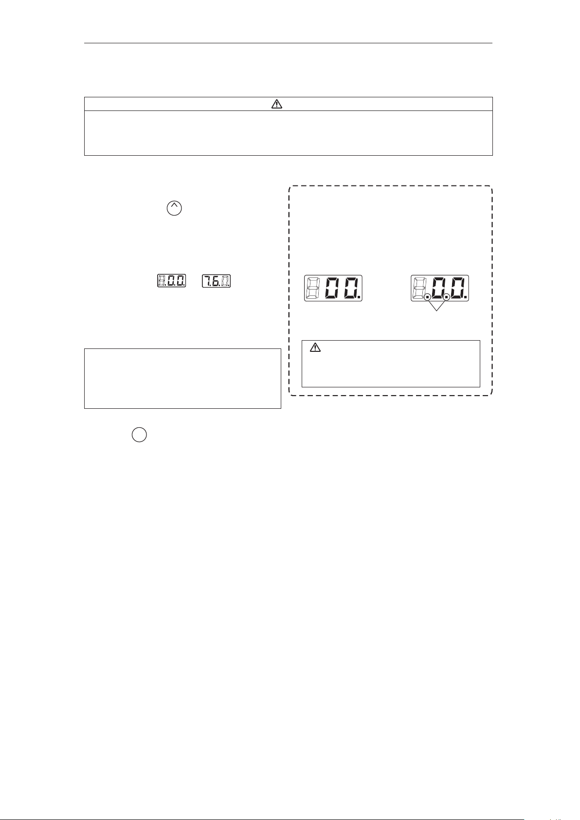
* How to distinguish between
Temperature Setting Mode and Adjustment Mode.
The display differs in the temperature setting
and the adjustment mode.
In the Temperature
Setting Mode
CAUTION
Please be sure to confirm the status of the
identification lamps so that you do not enter
a value in the wrong mode.
In the Adjustment Mode
Identification lamps are on
in the adjustment mode.
3. Press the button to exit the setting
after changing the values.
● The tip temperature will be adjusted accordingly.
ENTER
Page 6

5. OPERATION
● Restriction on setting changes (Password function)
It is possible to restrict certain setting changes to the unit.
There are three choices for the password setting. (The factory default is "0 : Open")
1 : Partial
×
△
△
△
Move to the parameter setting mode
Move to the temperature setting mode
Move to the preset selection mode
Move to the adjust mode
0 : Open
○
○
○
○
○ : You can make changes without entering a password.
△ : You can choose whether or not a password is needed to make changes.
×: A password is required to make changes.
2 : Restricted
×
×
×
×
Select and input three letters for password
from six letters on the right.
The letters
for password
Example:The procedure for changing the set temperature when the unit is restricted by a password.
(Password is "AbC")
Hold down the button
ENTER
Press the button once.
UP
for at least two seconds.
Press the button once.
Press the button twice.
UP
Press the button three times.
ENTER
UP
Press the button once.
ENTER
CAUTION
Press the button once.
ENTER
・If the password you entered is incorrect,
the display will show three dashes for you
to re-enter the password.
・If you enter the password incorrectly twice in a row,
the display will return to the previous screen.
The unit will move to the change setting screen for each mode after entering the password.
Please change the setting for each mode according to the procedure.
(In the above example, please refer to the procedure for setting the temperature
in normal mode [Section 5 - OPERATION].)
Page 7

6. PARAMETER SETTING
The FX-888D has the following parameters.
Parameter name
℃/F selection
Low temperature error setting
Setting mode selection
The number of preset *
Password setting
Temperature setting mode **
Preset selection mode **
Adjust mode **
Password ***
*It is displayed only when "1:Preset mode" is selected in the setting mode.
**It is displayed only when "1:Custom" is selected in the password setting.
***It is displayed only when either "1:Custom" or "2:valid" is selected in the password setting.
ParameterNo.
Value
54〜270℉ (30〜150℃)
The normal mode
pcs
Open Partial
Select three letters
The preset mode
pcs
Restricted
Initial value
℉
270℉
0
0
-
The HAKKO FX-888D has the following four parameters. Turn the power on while pressing the button.
Perform the setting to select the desired parameter No..
Press the button to change the values, and press the button to execute.
● :
℃ or ℉ temperature display seletion
UP
ENTER
UP
The displaed temperature can be switched between Celsius and Fahrenheit.
● :
Low temperature error setting
If the sensor temperature goes below the low-limit temperature although heating element is on,
an error will be displayed.
● :
Setting mode selection
Temperature setting can be switched between the normal mode and the preset mode.
If selecting the preset mode, you will be asked for the number of preset you required.
Press the button to set the number.
● :
Password setting
UP
Select "Open", "Partial" or "Restricted" for password setting.If selecting Restricted, perform the setting
for password. If selecting Partial, choose whether or not the password function is needed when moving
to the temperature setting mode, the preset mode and the adjust mode and set the password.
■Parameter entering mode
1. Turn off the power switch.
2. Turn on the power switch while pressing the button.
UP
3. When the display shows , the station is in parameter entering mode.
Page 8

6. PARAMETER SETTING
■Parameter entering mode
●℃ or ℉ temperature display selection
1. Either or will be displayed if you press the button when is displayed.
ENTER
2. and will be switched alternately if you press the button.
3. The display will return to if you press the button after selecting.
ENTER
UP
● Low temperature error setting
1. Press the button to change the display to .
2. The low-limit temperature will be displayed if you press the button. Enter the value in the same
UP
ENTER
manner as setting the temperature in the normal mode [5. OPERATION ●The normal mode]
3. The display will return to if you press the button after setting.
ENTER
● Setting mode selection
1. Press the button to change the display to .
2. If you press the button, the display will move to the setting mode selection screen. If you press
the button, (The normal mode) and (The preset mode) will be switched alternately.
3. The display will return to if you press the button after selecting.*
UP
ENTER
UP
ENTER
* If you select the preset mode, the display will move to the preset selection screen.
4.The number of active preset will be displayed If you press the button at 3.
ENTER
(Example : If the number is three, is displayed.)
5. Press the button to change the value and select the number of active preset you required.
UP
The unit will accept values from 2 through 5.
6. The display will return to if you press the button after selecting.
ENTER
Page 9

6. PARAMETER SETTING
● Password setting
1. Press the button to change the display to .
2. If you press the button, the display will move to the password setting mode selection screen.
If you press the button, (Open), (Partial) and (Restricted) will be switched
UP
ENTER
UP
alternately.
3. If you press the button after selecting, the display will return to . ※1、2
ENTER
※1 The display will move to the following selection screen if you select (Partial).
4. If you press the button at 3, you will be asked whether or not the password function is needed when
ENTER
moving to the temperature setting mode.
5. Either (without password) or (with password) will be displayed if you press the button.
6. If you press the button after selecting, you will be asked whether or not the password function is
ENTER
UP
needed when moving to the preset selection mode.
7. Either (without password) or (with password) will be displayed if you press the button.
8. If you press the button after selecting, you will be asked whether or not the password function is
ENTER
UP
needed when moving to the adjust mode.
9. Either (without password) or (with password) will be displayed if you press the button.
10. If you press the button after selecting, the display will move to password setting screen.
ENTER
UP
If you select (Restricted), the display will move to the following password setting screen.
※2
If you select (Partial), the display will move to the following the password setting screen after selecting ※1.
11. The hundreds digits in the display will begin to flash. It indicates that you can enter the value.
Press the button to enter the letter you required.
12. The tens digits in the display will begin to flash if you press the button after entering.
UP
ENTER
Use the same procedure to enter the letters for tens and units digit.
13. The display will return to if you press the button after entering the units digit.
After changing parameters, press and hold the button down for at least two seconds until is displayed.
ENTER
At this time, you can switch between and by pressing the button. Select if you are
finished making changes or if you need to go back and make more changes. Press the button to
ENTER
UP
ENTER
confirm you selection.
Changes will not be completed until is displayed and you press the button.
ENTER
Please note that no changes will be made if you turn off the power while making changes.
Page 10

7. MAINTENANCE
Performing proper and periodic maintenance extends product life. Efficient soldering depends upon
the temperature, quality and quantity of the solder and flux.
Apply the following service procedure as dictated by the conditions of usage.
Since the soldering iron can reach a very high temperature, please work carefully. Except the case
especially indicated, always turn the power switch OFF and disconnect the power plug before performing
any maintenance procedure.
●Tip Maintenance
1. Set the temperature to 482℉ (250℃).
2. When the temperature stabilizes, clean the tip with the cleaning sponge and check the condition of the tip.
3. If the solder plated part of the tip is covered with black oxide, apply fresh solder containing flux, and clean
the tip again. Repeat until all the oxide is removed, then coat the tip with fresh solder.
4. If the tip is deformed or heavily eroded, replace it with a new one.
■ Cleaning the tip using the iron holder
1. Using the cleaning sponge
2. Using the cleaning wire
Use the cleaning sponge that comes with the product
to clean the tip. It offers wide-ranging uses, from simple
removal of excess solder to complete elimination of
matter occurring as a result of oxidization.
Material that is not removed easily with the cleaning
sponge can likely be removed using the cleaning wire.
Page 11

8. CHECKING PROCEDURE
Disconnect the plug of the cord assembly and measure
the resistance value between the pins of the
connecting plug as follows.
The power lamp starts to flash when the
temperature reaches 880℉ (480℃) regardless
of the condition of the cord.
1.Turn the unit ON and set the temperatureto 480℃.
Then bend the iron cord at various locations along its length,
including in the strain relief area. The cord assembly needs
to be replaced if S-E is displayed or although the LED heater
lamp flashes, the tip temperature doesn’t rise.
Page 12

9. TROUBLE SHOOTING GUIDE
Before checking the inside of the FX-888D or replacing parts, be sure to disconnect the power plug.
If the cord assembly is broken, replace the HAKKO FX-8801. If the
heating element / sensor is broken, replace the heating element.
● The Heater- error is
displayed.
Is the heater broken?
If the heater is broken, replace the heating element.
If the cord assembly is broken, replace the HAKKO FX-8801.
Is the iron temperature adjusted correctly?
Perform the temperature adjustment.
Is the iron temperature adjusted correctly?
Perform the temperature adjustment.
Page 13

10. TIP STYLES
T18-B SHAPE-B T18-SB SHAPE-SB T18-BL SHAPE-BLT18-BR02 SHAPE-0.2BR
4
30°
R0.2
10.5
T18-C08 SHAPE-0.8C
φ0.8
15.5
T18-C3 SHAPE-3C
T18-CF3*
T18-C1 SHAPE-1C
T18-CF1*
T18-C4 SHAPE-4C
T18-CF4*
T18-C5 SHAPE-5C
φ5
14.5
T18-D12 SHAPE-1.2D T18-D16 SHAPE-1.6D T18-D24 SHAPE-2.4D
T18-DL2 SHAPE-2DL
φ2
1
22.5
T18-S7 SHAPE-S7
T18-DL32 SHAPE-3.2DL
φ3.2
1
22.5
T18-S9 SHAPE-S9
T18-S3 SHAPE-S3
φ5.2
1
18
T18-IS SHAPE-IS
T18-C05 SHAPE-0.5C
R0.2
22.5
T18-C2 SHAPE-2C
T18-CF2*
T18-CSF25* SHAPE-2.5CST18-CF15* SHAPE-1.5C
T18-K SHAPE-K T18-D08 SHAPE-0.8D
T18-D32 SHAPE-3.2D T18-DL12 SHAPE-1.2DL
φ1.2
0.7
22.5
T18-S4 SHAPE-S4
R0.125
14.5
T18-S6 SHAPE-S6
φ1.3
60°
16.5
T18-I SHAPE-I
φ1.2
60°
14.5
φ1.2
0.4
15.5
R0.2
11
* Tinned on the soldering surface only.
● Use only genuine Hakko soldering iron tips. Replacement tips for the HAKKO FX-888D
are designated the T18 series.
Page 14

11. PARTS LIST
M4 × 38(4)
● HAKKO FX-888D Station
Item No.
1
2
3
4
Part No.
B3733
B3734
B3735
B3736
B3741
B3742
B3743
B3744
B3745
B3746
B3747
B3748
B3749
Part Name
Chassis
Front panel / Yellow
Front panel / Gray
P.W.B
Power cord, 3 wired cord
& American plug
Power cord, 3 wired cord
but no plug
Power cord, 3 wired cord
& BS plug
Power cord, 3 wired cord
& European plug
Power cord, 3 wired cord
& BS plug
Power cord, 3 wired cord
& Australian plug
Power cord, 3 wired cord
& Chinese plug
Power cord, 3 wired cord
& SI plug
Power cord, 3 wired cord
& American plug (B)
3 × 12(4)
Specifications
For BY
For SV
For temperature control
With tube, USA
With tube
With tube
With tube, CE
With tube, CE
With tube
With tube
With tube
With tube
Item No.
5
6
7
8
9
10
11
12
Part No.
B3737
B3738
B3739
B3750
B3450
B3452
B3721
B3722
B3680
B3723
B3724
B3463
B2852
B2227
B2405
Part Name
Transformer
Transformer
Transformer
Cord stopper
Upper case / BY
Upper case / SV
P.W.B / 100V
P.W.B / 110 -120V
P.W.B / 220V
P.W.B / 230V
P.W.B / 240V
Receptacle
Switch
Grounding plate
Rubber feet
Specifications
100-110V
120V
220-240V
With fuse and rubber feet
With fuse and rubber feet
With fuse and rubber feet
With fuse and rubber feet
With fuse and rubber feet
Page 15

11. PARTS LIST
Part No.
FX8801-02
A1559
B3472
B3473
B3474
B3475
B3476
A1561
Instruction manual in the language of Japanese, English, Chinse, French, German and Korean
can be downloaded from the HAKKO Document Portal.
(Please note that some languages may not be available depending on the product.)
Copyright © 2012 HAKKO Corporation. All Rights Reserved.
MA02470XZ120517
2012.5
 Loading...