

Page 1

SolderingStation
Instruction Manual
●
ThankyouforpurchasingtheHAKKOFX-801SolderingStation.
PleasereadthismanualbeforeoperatingtheHAKKOFX-801.
Keepthismanualreadilyaccesibleforreference.
●
TABLEOFCONTENTS
1. PACKING LIST
2. SPECIFICATIONS
3. WARNINGS, CAUTIONS AND NOTES
4. PART NAMES
5. INITIAL SETUP
6. OPERATION
7. PARAMETER SETTING
8. MAINTENANCE
9. CHECKING PROCEDURE
10. ERROR MESSAGES
11. TROUBLE SHOOTING GUIDE
12. PARTS LIST
13. WIRING DIAGRAM
........................................................ 1
................................................... 1
......................................................... 3
........................................................ 4
............................................................ 5
........................................ 10
..................................................... 16
.................................... 17
............................................. 18
............................. 19
.......................................................... 21
................................................ 23
.................. 2
Page 2
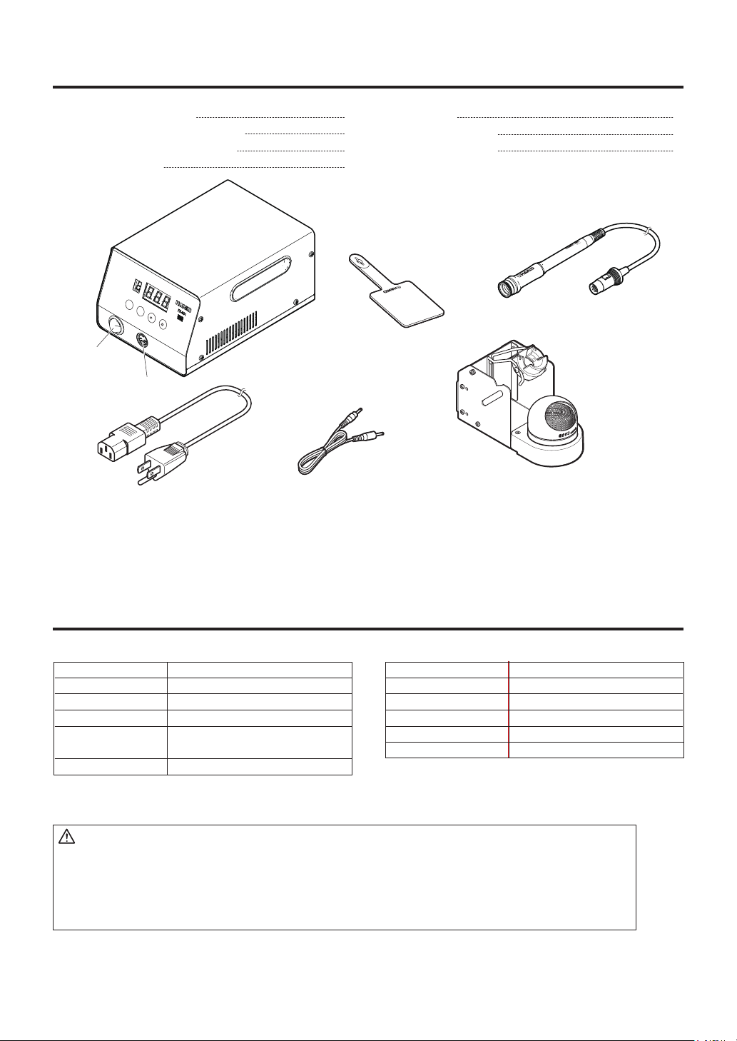
1. PACKING LIST
Please check to make sure that all items listed
below are included in the package.
HAKKO FX-801 Station
HAKKO FX-8002 Soldering iron
Iron holder (with cleaning wire)
Connecting cable
UP
DOWN
Power
switch
Receptacle
Power cord
HAKKO FX-801
Power cord
1
Heat resistant pad
1
Instruction manual
1
1
Heat resistant pad
Connecting cable
1
1
1
FX-8002
HAKKO FX-8002
Iron holder
* Tip (T33 series) is optionally
available.
2. SPECIFICATIONS
● HAKKO FX-801
Power consumption
Temperature range
Temperature stability
Output Voltage
Dimensions
Weight
* The temperature was measured using the FG-100 thermometer.
* This product is protected against electrostatic discharge.
* Specifications and design are subject to change without notice.
300W
50 - 500℃ (120 - 940℉)
± 5℃ (± 9℉) at idle temperature
AC 29V
145(W)×107(H)×211(D) mm
(5.7 × 4.2 × 8.3 in.)
3.9 kg (8.6 lb.)
CAUTION
This product includes such features as electrically conductive plastic parts and grounding of the handpiece and station as
measures to protect the device to be soldered from the effects of static electricity. Be sure to observe the following instructions:
1. The handle and other plastic parts are not insulators, they are conductors. When replacing parts or repairing,
take sufficient care not to expose live electrical parts or damage insulation materials.
2. Be sure to ground the unit during use.
1
● HAKKO FX-8002
Power Consumption
Tip to Ground Resistance
Tip to Ground Potential
Cord
Total Length (w/o cord)
Weight (w/o cord)
260W (29V)
< 2 Ω
< 2 mV
1.2 m (4 ft)
228 mm (9.0 in.) with 4BC tip
50 g (0.11 lb.) with 4BC tip
Page 3
3. WARNINGS, CAUTIONS AND NOTES
Warnings, cautions and notes are placed at critical points in this manual to direct the
operator’s attention to significant items. They are defined as follows:
Failure to comply with a WARNING may result in serious injury or death.WARNING:
CAUTION :
Failure to comply with a CAUTION may result in injury to the operator, or damage to the
items involved.
WARNING
When power is ON, the tip will be hot.
To avoid injury or damage to personnel and items in the work area, observe the following:
● Do not touch the tip or the metal parts near the tip.
● Do not allow the tip to come close to, or touch, flammable materials.
● Inform others in the area that the unit is hot and should not be touched.
● Turn the power off when not in use, or left unattended.
● Turn the power off when changing parts or storing the HAKKO FX-801.
● This appliance can be used by children aged from 8 years and above and
persons with reduced physical, sensory or mental capabilities or lack of
experience and knowledge if they have been given supervision or instruction
concerning use of the appliance in safe way and understand the hazards
involved.
● Children shall not play with the appliance.
●
Cleaning and user maintenance shall not be made by children without supervision.
● The unit is for a counter or workbench use only.
To prevent accidents or damage to the HAKKO FX-801, be sure to observe the following:
CAUTION
● Do not use the HAKKO FX-801 for applications other than soldering.
● Do not strike the iron against hard objects to remove excess solder.
This will damage the iron.
● Do not modify the HAKKO FX-801.
● Use only genuine Hakko replacement parts.
● Do not allow the HAKKO FX-801 to become wet, or use it with wet hands.
● Remove power and iron cords by holding onto the plug.
● Be sure the work area is well ventilated. Soldering produces smoke.
● Be sure the cooling fan at the rear of the station is unrestricted.
● While using the HAKKO FX-801, don’t do anything which may cause bodily harm or
physical damage.
2
Page 4
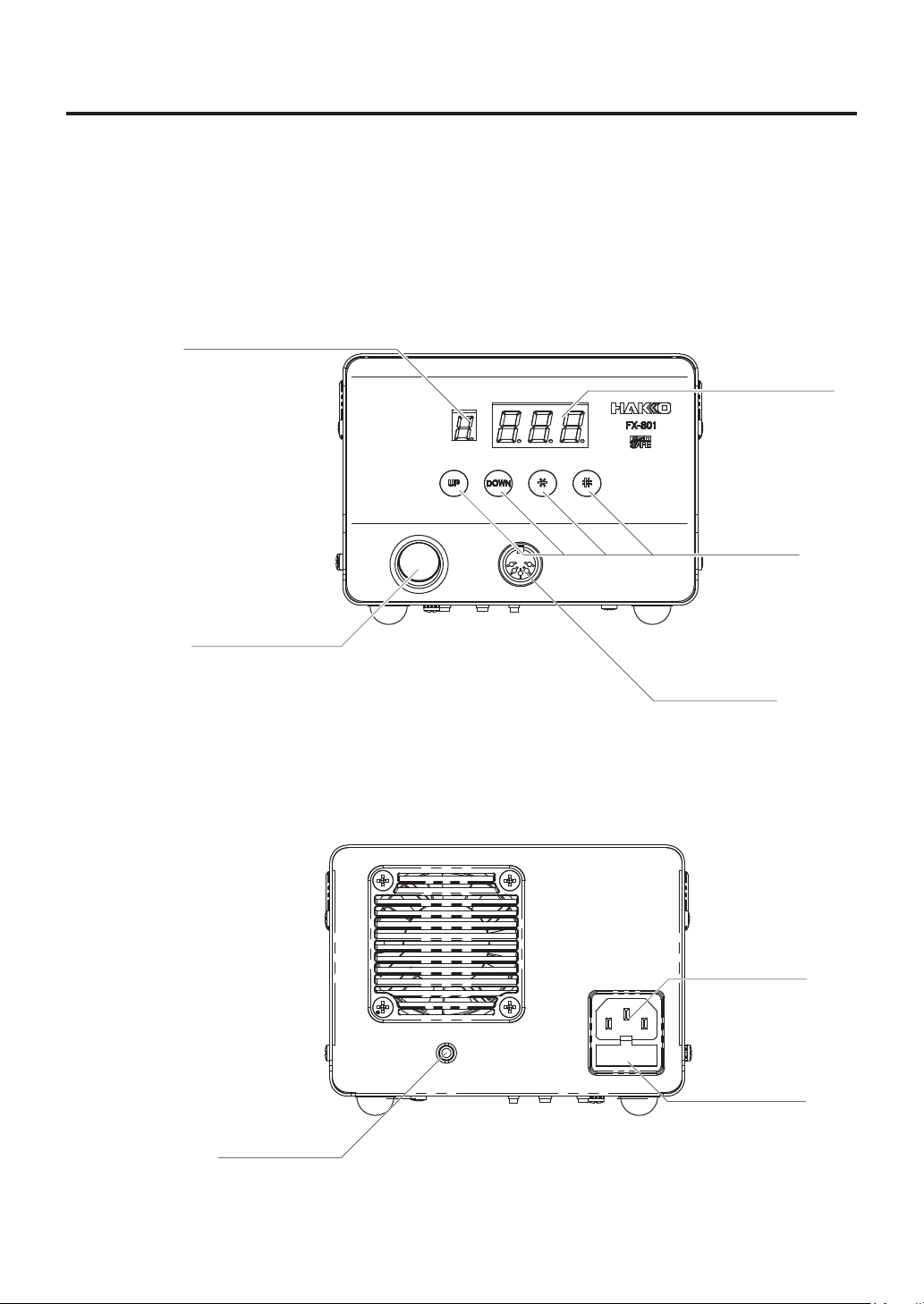
4. PART NAMES
● HAKKO FX-801
Preset number display
Setting display
Control buttons
Power switch
Jack
(for connecting
cable)
Receptacle
Power cord
receptacle
Fuse
3
Page 5
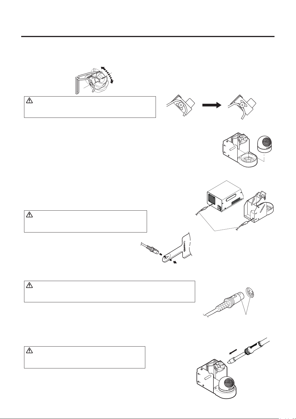
5. INITIAL SETUP
A. Iron holder
● Loosen the adjusting screws to change the angle
of the iron receptacle as you like, then tighten the
screws.
CAUTION
Do not set up the iron receptacle too high, the
temperature of the soldering iron will become very hot.
1. Assemble as shown:
● Insert the tip cleaner securely into the Iron holder base.
2. Operation:
First, remove any excess solder from the tip by thrusting the tip into the cleaning
wire. (Do not wipe the tip against the wire. This may cause molten solder to
spatter.) When the wire becomes dirty or loaded with solder, turn the wire until a
clean surface is presented. When changing the cleaning wire, lift the case top
vertically to prevent solder debris from falling out.
● Use of the sleep function.
When using the sleep function, insert one end of the connecting cable
into the jack at the back of the iron holder and the other end into the
jack at the back of the soldering station to connect them.
CAUTION
Be sure to turn off the power before connecting or
disconnecting the connecting cable.
The iron receptacle has two grooves. If the edge
of the iron tip is likely to come into contact with the
iron holder or the iron holder becomes hot, use the
alternate groove to attach the iron receptacle.
Normal conditions
If the iron holder
becomes hot
Connecting cable
B. Handpiece cord assembly
Pass the iron cord through the hole in the heat
resistant pad.
C. Soldering station
CAUTION
Be sure the power switch is OFF before connecting or disconnecting the
soldering iron cord. Failure to do so may result in damage to the circuit board.
1. Insert the power cord into the receptacle at the back of the station.
Insert the soldering iron cord into the receptacle at the front of the
station.
2. Set the iron in the iron holder.
3. Plug the power cord into a grounded wall socket.
CAUTION
The HAKKO FX-801 is protected against electrostatic
discharge and must be grounded for full efficiency.
Insert the plug into
the receptacle until
it clicks.
To disconnect, pull the plug
from the receptacle while
pressing down the tab on
the plug.
4
Page 6
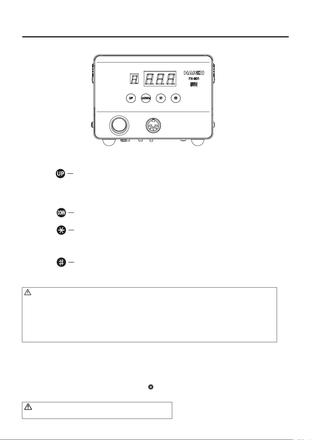
6. OPERATION
The HAKKO FX-801 has the following four control buttons.
Press for less than one second to enter preset number selection screen.
Press and hold for at least one second to enter preset temperature
changing screen.
Use to increase the value in the appropriate display window.
Use to decrease the value in the appropriate display window.
Press for less than one second to display the current set temperature.
Press and hold for at least one second to enter temperature setting mode.
Use to end the current operation.
Press for less than one second to display the current offset value.
Press and hold for at least one second to enter offset mode.
CAUTION
An audible buzzer is provided to alert the operator when:
● The station has reached the set temperature, a buzzer will sound once.
● The low temperature threshold has been crossed, a buzzer will sound continuously.
This buzzer will shutoff when the sensed temperature returns to the acceptable range.
● There is the possibility that a failure has occured in the sensor or heater, a buzzer will
sound continuously.
Operation
1. Turn on the power switch.
2. Once the set temperature is reached, a buzzer sounds once.
By default, the temperature is set to 350℃ (750℉ for US model).
Check the temperature setting by pressing the button.
The set temperature will be displayed for two seconds.
WARNING
Place soldering iron in iron holder when not in use.
5
Page 7
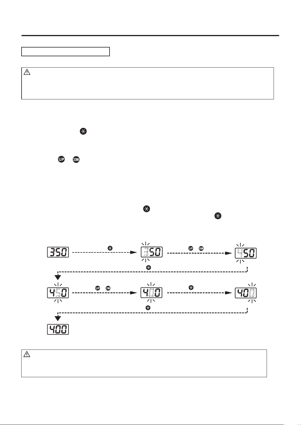
Changing temperature setting
CAUTION
The temperature setting range is from 50℃ to 500℃. (120℉ to 940℉)
●If you enter a value outside the temperature setting range, the display returns to the hundreds
digit, and you have to enter a correct value.
Example:Changing set temperature from 350 to 400℃
1.Press and hold the button for at least one second.
The hundreds digit will begin to flash.
2. Entering the value.
Press the or to set the value of the digit that is flashing.
Only values from 0 to 5 can be selected when entering the hundreds digit.
(In ℉ mode, values from 1 to 9 can be selected.)
Values from 0 to 9 can be selected when entering the tens or ones digit.
(The same values can be selected in ℉ mode.)
When desired figure is displayed, press the button to accept the value.
The next digit will begin to flash. After entering the ones digit, press the button to save
the value to the system memory and begin heater control with new setting temperature.
Press and hold the button
for at least one second.
Press the button once.
Press the or button.
Press the button once.
Press the or button.
Press the button once.
CAUTION
If power is switched off or lost during the execution of this procedure, no data will be entered.
The entire procedure must be repeated from step 1.
6
Page 8

Selecting the preset number
You can quickly select one of six user programmable preset temperatures.
Initial preset temperatures are: 0:300℃, 1:350℃, 2:375℃, 3:400℃, 4:450℃ and 5:500℃.
Example:Changing preset No. 0 (300℃) to No. 3 (400℃)
1. Press the button once.
Preset number display will begin to flash.
2. Press the button three times to change the preset number display to .
3. Press the to set the value.
Press the button
once.
Press the button
three times.
Press the button
once.
Changing the preset temperature
You can change any of the six available preset temperatures. (Preset No. 0 to No. 5)
Example:Changing Preset No. 3 temperature from 400℃ to 410℃.
1. Press and hold the button for at least one second.
Both preset number display and setting display will begin to flash.
2. Press the button three times to change the preset number display to .
3. Press the button to set the value.
4. Use the method for setting the temperature to enter and set the preset temperature.
Press and hold the button
for at least one second.
Press the button once.
Press the button
three times.
Press the button once.
Press the button once.
Press the button once.
Press the button once.
7
Page 9

Entering the tip offset value
Example:If the measured temperature is 410℃ and set temperature is 400℃, the difference
is -10℃ (need to decrease by 10℃). So enter a value so 10 is deducted from present
offset value.
1. Press and hold the button for at least one second.
The hundreds digit will begin to flash, the unit will enter the offset mode.
2. Enter the offset value (-10) which is the difference between tip temperature and set temperature.
The allowable ranges for offset values are from -50 to +50℃ (In ℉ mode, from -90 to +90℉)
If you enter a value outside the offset value range, the display returns to the hundreds digit,
and you have to enter a correct value.
3. Entering the value.
Press the or button to set the desired figure.
The hundreds digit can display 0 (for positive value) or minus sign (for negative value)
(Same values can be selected in ℉ mode.)
Values from 0 to 5 can be selected when entering the tens digit.
(In ℉ mode, values from 0 to 9 can be selected.)
Values from 0 to 9 can be selected when entering the ones digit.
(Same values can be selected in ℉ mode.)
After entering the ones digit, press the button to save the value to the system memory
and begin heater control with the new offset value.
Press and hold the button
for at least one second.
Press the button
once.
Press the button
once.
Press the button
once.
Press the button
once.
CAUTION
Do not enter an offset that allows the tip to exceed 500 ℃.
8
Page 10

Restriction on setting changes (Password function)
It is possible to restrict certain setting changes to the unit.
There are three choices for the password setting. (The factory default is "0 : Open")
0 : Open
Parameter setting mode
Temperature setting mode
Preset selection mode
Offset mode
○
○
○
○
○ : You can make changes without entering a password.
△ : You can choose whether or not a password is needed to make changes.
×: A password is required to make changes.
Select and input three letters for the password
from six letters on the right.
Example : The procedure for changing the set temperature when the unit is restricted by a password.
(Password is "AbC")
1 : Partial
×
△
△
△
2 : Restricted
×
×
×
×
Press and hold the button
for at least one second.
Press the button once.
Press the button twice.
Press the button three times.
Press the button once.
Press the button once.
CAUTION
・If the password you entered is incorrect, the
Press the button once.
display will show three dashes for you to re-enter
the password.
・If you enter the password incorrectly twice in a
row, the display will return to the previous screen.
The unit will enter the change setting screen for each mode after entering the password.
Please change the setting for each mode according to the procedure.
(In the above example, please refer to the procedure for setting the temperature.)
Enter the parameter setting to change the mode. (Please refer to [7. PARAMETER SETTING])
9
Page 11

7. PARAMETER SETTING
Parameter name
Temperature display
Auto sleep time setting
Low temperature error setting
Buzzer setting
(S-E sound , C-E sound)
Buzzer setting
(set temperature achieving alert)
Auto sleep on/off setting
Auto shutoff on/off setting
Power-mode setting
Auto sleep temperature setting
Password lock setting
Changing the set temperature
Changing the preset number
Changing the offset value
Password
Auto shutoff time setting
* ○ : Password not required × : Password required
** For U.S.A.
Parameter number
Settings
℉( )/℃( )
0 - 29 min.
30 - 300℃ (54 - 540℉)
OFF( )/ON( )
OFF( )/ON( )
OFF( )/ON( )
OFF( )/ON( )
High power( )/Normal power( )
200 - 300℃ (390 - 580℉)
Open
( ) /
: ○* / : ×*
: ○* / : ×*
: ○* / : ×*
30 - 60 min.
Partial
( ) /
Select three letters
Restricted
Initial value
℃ (℉**)
6 min.
300℃ (540℉**)
ON ( )
ON ( )
ON ( )
OFF ( )
High power( )
200℃ (400℉**)
Open( )
( )
30 min.
Turn on the power switch while pressing the button, the station will enter the parameter
setting mode. (When the display shows flashing, the station is in the parameter setting mode.)
Use the or button to select parameter number and press the button to move to next step.
Use the or button to select and press the button to set the desired parameter value.
After the necessary parameters are set, press and hold the button for at least one second.
The display changes to (Yes) and press the button to exit the parameter entry mode.
If you press the or button to select (No), you will return to previous screen.
CAUTION
If the power is switched off or lost during the execution of this procedure, no data will be entered.
10
Page 12

● :℃ or ℉ temperature display selection
1. In display setting mode, either
or
is displayed
: The display shows temperatures in Celsius
: The display shows temperatures in Fahrenheit
2.
3. The display will return to
and
will be switched alternately if you press the ( ) button.
if you press the button after selection.
● :Auto sleep time setting
Set the time until the auto sleep function activates after the soldering iron is set on the iron holder.
Auto sleep examples:
NOTE:The auto sleep time can be set in units of minutes (up to 29 minutes).
When the display is
Sleep activated (immediately after the iron is set on the iron holder)
Sleep activated (10 minutes after the iron is set on the iron holder)
, press the or button, or remove the soldering iron from the
iron holder to resume power to the heater.
Select a parameter
number 02
The display will return to
Press the or botton
Press the button once
Press the button once
Press the or botton
if you press the button after selection.
CAUTION
• When the temperature setting is 300ºC (570ºF) or less, the sleep function will not activate
Sleep even if the sleep function is turned ON.
• The tip temperature will rise to the set temperature during the initial power up even if the sleep
time is set to “0” . The tip temperature will be reduced to the sleep temperature after the
temperature reaches the set temperature.
11
Page 13

● : Low temperature error setting
When the temperature drops below a set limit, an error is displayed and the buzzer sounds.
When the temperature returns within the allowable range, the buzzer stops.
Low temperature setting range : for Celsius: 30 to 300ºC
for Fahrenheit: 54 to 540ºF
Example : When the set temperature is 350ºC and the low temperature error setting is 100ºC, a
warning buzzer sounds when the temperature drops to 250ºC.
1. The hundreds digit begins to flash when entering the low temperature setting.
2. If you enter a value outside the low temperature setting range (see the acceptable range above),
the display returns to the hundreds digit, and you have to enter a correct value.
3. The display will return to
if you press the button after selection.
● : S-E, C-E Buzzer sound setting mode
1. In the buzzer sound setting mode, either
: The buzzer does not sound if a sensor or connector error occurs.
: The buzzer sounds if a sensor or connector error occurs.
2.
3. The display will return to
and
will be switched alternately if you press the ( ) button.
if you press the button after selection.
or
is displayed.
● : Set temperature alert setting mode
1. In the set temperature alert setting mode, either
: The buzzer does not sound when the soldering iron reaches the set temperature.
: The buzzer sounds when the soldering iron reaches the set temperature.
2.
3. The display will return to
and
will be switched alternately if you press the ( ) button.
if you press the button after selection.
or
is displayed.
● : Auto sleep on/off setting
NOTE: When the auto sleep function is on, removing the iron from the iron holder or pressing the
button resumes operations.
1. In the auto sleep setting mode, either
: The auto sleep function is off, regardless of the auto sleep set time.
: The auto sleep function is on, and the auto sleep time is activated.
2.
3. The display will return to
and
will be switched alternately if you press the ( ) button.
if you press the button after selection.
or
is displayed.
12
Page 14

● : Auto shutoff on/off setting
When the auto shutoff function is set to on and no operation is performed for 30 minutes (
) after the iron is set in the iron holder, the buzzer sounds and the auto shutoff function will be
value
enabled. Leaving the iron in the iron holder as it is, the buzzer sounds every 30 minutes.
1. In the auto shutoff setting mode, either
: The auto shutoff function is off, regardless of the auto sleep function set time.
: The auto shutoff function is on, and the auto shutoff time is activated.
2.
3. The display will return to
and
will be switched alternately if you press the ( ) button.
if you press the button after selection.
or
is displayed.
Initial
● : Power-mode setting
NOTE: High-power mode is mainly suited for applications that require large heat capacity such
as quick soldering of ground patterns or cast metal products.
1. In the Power-mode setting mode, either
: Selects High power mode.
: Selects Normal power mode.
or
is displayed.
2.
3. The display will return to
CAUTION
If the tip is overloaded, it may cause overshooting.
and
will be switched alternately if you press the ( ) button.
if you press the button after selection.
● : Auto sleep temperature setting
Sets the auto sleep temperature. Setting a high sleep temperature enables shorter start up time
when the unit recovers from sleep mode.
CAUTION
Setting the sleep temperature too high will shorten tip life.
Auto sleep temperature setting range : for Celsius: 200ºC to 300ºC
for Fahrenheit: 390ºF to 580ºF
1. When the unit enters auto sleep temperature setting mode, the hundreds digit starts flashing. Enter
a desired value within the auto sleep temperature setting range.
2. If the entered value exceeds the auto sleep temperature setting range (see acceptable values
above), the hundreds digit starts flashing again. If this happens, enter a correct value.
3. The display will return to
if you press the button after selection.
13
Page 15

● : Password setting
If selecting Restricted, perform the setting for password. If selecting Partial, choose whether or not
the password function is needed when changing the set temperature, the preset number and the
offset value and set the password.
1. Either , or will be displayed if you press the button when is
displayed.
2. If you press the ( ) button, (Open), (Partial) and (Restricted) will
be switched alternately.
3. The display will return to
*1 The display will move to the following selection screen if you select (Partial).
4. After pressing the button, you will be asked whether or not the password function is needed when
moving to the temperature setting mode.
5. Either (without password) or (with password) will be displayed if you press the
( ) button.
6. If you press the button after selecting, you will be asked whether or not the password function is
needed when moving to the preset selection mode.
7. Either (without password) or (with password) will be displayed if you press the
( ) button.
8. If you press the button after selecting, you will be asked whether or not the password function is
needed when moving to the offset mode.
9. Either (without password) or (with password) will be displayed if you press the
( ) button.
10. The display will return to 14 after pressing the button.
if you press the button after selection.
*1, 2
*2
If you select (Restricted), the display will move to the following password setting screen.
If you select (Partial), the display will move to the following the password setting screen
after completing ※1.
11. The hundreds digits in the display will begin to flash. It indicates that you can enter the letter.
Press the ( ) button to enter the letter you required.
12. The tens digits in the display will begin to flash if you press the button after entering.
Use the same procedure to enter the letters for tens and ones digit.
13. The display will return to if you press the button after entering the ones digit.
14
Page 16

● : Auto shutoff time setting
Set auto shutoff time. The setting is possible within 30 to 60 minutes, in one minute increments.
1. Auto shutoff time (Initial value is 30 minutes) will be displayed if you press the button when
is displayed.
2. Press the ( ) button, you can change to the desired value. Enter a value from 30 to
60 (minutes).
3. The display will return to
if you press the button after selection.
15
Page 17

8. MAINTENANCE
Performing proper and periodic maintenance extends product life and contributes to the quality
of soldering work. Efficient soldering depends upon the temperature, the quality and quantity
of the solder and flux. Apply the following service procedure as dictated by the conditions of the usage.
WARNING
Since the soldering iron can reach a very high temperature, please work carefully.
Except where indicated, always turn the power switch OFF and disconnect the
power plug before performing any maintenance procedure.
●Tip maintenance
1. Tip temperature
High temperatures shorten tip life and may cause thermal shock to components. Always use the
lowest
HAKKO FX-801
2. Cleaning
Always clean the soldering iron tip before use, to remove any residual solder or flux adhering to it
by using a tip cleaner. Contaminants on the tip have many deleterious effects, including reduced
heat conductivity, which contribute to poor soldering performance.
possible temperature when soldering. The excellent thermal recovery characteristics of the
ensures effective soldering at low temperatures.
3. After use
Always clean the tip and coat it with fresh solder after use.
This guards against oxidation.
4. When the unit is not being used
Never allow the unit to idle at a high temperature for extended periods. This will cause the tip to
become oxidized. Turn the power switch OFF. If it is to be out of service for several hours, it is
advised to disconnect the power plug as well.
5. Inspecting and cleaning the tip
If followed daily, this procedure will materially add to tip life.
a. Set the temperature to 250℃ (482℉).
b. When the temperature stabilizes, clean the tip and check the condition of the tip.
If the tip is badly worn or deformed, replace it.
c. If the solder plated part of the tip is covered with black oxide, apply fresh solder, containing flux,
and clean the tip again. Repeat until all the oxide is removed, then coat the tip with fresh solder.
d. Turn the power OFF and remove the tip, using the heat resistant pad. Set the tip aside to cool.
Remaining oxides can be removed with isopropyl alcohol.
CAUTION
NEVER file or use abrasive materials on the tip to remove oxides!
16
Page 18

9. CHECKING PROCEDURE
WARNING
Unless otherwise directed, carry out these procedures with power switch OFF and the power UNPLUGGED.
■Check for a broken heater or sensor
Verify the electrical integrity of the heater and sensor.
Measure the resistance of the heater and sensor while at room temperature (15℃ to 25℃; 59℉ to 77℉)
It should be 3.4Ω±10%. If the resistance exceeds these limits, replace it.
Measure the heater/sensor resistance between these points.
■Check the grounding line
1. Unplug the iron cable from the station.
2. Measure the resistance between pin #2 and the soldering iron tip (with iron cable connected to
the HAKKO FX-8002).
3. If the value exceeds 2Ω (at room temperature), perform the tip maintenance in page 16.
If the value still does not decrease, check the connection cord for breakage.
2
■Check the iron cable for breakage
Measure the resistance of the connector pin.
Between Pin #1 to Pin #3 - 3.0 to 3.8Ω
If the resistance exceeds these limits, replace the iron cable.
Contact your HAKKO representative.
5
3
7
4
1
8
6
■Replace the fuse
1. Unplug the power cord from the power receptacle.
2. Remove the fuse holder.
3. Replace the fuse.
4. Put the fuse holder back in place.
17
Page 19

10. ERROR MESSAGES
● Sensor error
● Soldering iron error
● Low-temperature alarm
tolerance error
When there is a possibility that a failure has occured
in the sensor or heater (including the sensor circuit),
is displayed and a buzzer sounds.
is displayed and a buzzer sounds if the iron cable
is not attached to the station or a wrong soldering iron
is connected.
If the tip temperature falls below the low-temperature
alarm limit, is displayed and a buzzer sounds.
When the tip temperature rises above the lowtemperature alarm limit, the buzzer will stop.
Example:
350°C (400°C – 50°C)
Set temperature
Low-temperature alarm tolerance
● Heater terminal short
circuit error
● System error
is displayed and a buzzer sounds when the tip is
inserted incorrectly, an incompatible tip is inserted,
or when a foreign object has found its way into the
connector.
When a system error occurs such as data flash,
the soldering iron is immediately de-energized and
is displayed.
18
Page 20

11. TROUBLE SHOOTING GUIDE
● The unit does not operate when the power switch is turned ON.
CHECK : Is the power cord and/or the connection plug disconnected?
ACTION:Correctly connect the power cord.
CHECK:Is the fuse down?
ACTION:Investigate why the fuse blew and then replace the fuse.
If the fuse blows again, send the unit in for repair.
● The tip does not heat up.
・The sensor error is displayed.
CHECK:Is the tip inserted properly?
ACTION:Insert the tip completely.
CHECK:Check the iron cable and/or the heater/sensor for breakage.
ACTION:See “■ Checking the iron cable for breakage” and “■ Check for a
broken heater or sensor” in page 17. Replace any faulty part.
● Solder does not wet the tip.
CHECK:Is the tip temperature too high?
ACTION:Set the appropriate temperature.
CHECK:Is the tip contaminated with oxide?
ACTION:
(See “● Tip maintenance” in page 16.)
Remove the oxide.
● The tip temperature is too high
CHECK:Is the iron cable broken?
ACTION:See “■ Checking the iron cable for breakage” in page 17.
CHECK:Is the entered offset value correct?
ACTION:Enter the correct offset value.
● The tip temperature is too low.
CHECK:Is the tip contaminated with oxide?
ACTION:Remove the oxide.
(See “● Tip maintenance” in page 16.)
CHECK: Is the entered offset value correct?
ACTION: Enter the correct offset value.
● The soldering iron error is displayed.
CHECK:Is the proper soldering iron connected? Or, is the iron cable properly
connected?
ACTION:Re-connect the HAKKO FX-8002 iron cable to the station.
19
Page 21

●The low-temperature alarm tolerance error is displayed frequently.
CHECK : Is the tip too small for the work being soldered?
ACTION:Use a tip with a larger thermal capacity.
CHECK:Is the setting value for the low-temperature alarm tolerance too low?
ACTION:Increase the setting value.
●Heater terminal short circuit error is displayed.
CHECK: Is the tip for the HAKKO FX-8002?
ACTION:Turn the power switch OFF and insert the genuine HAKKO FX-8002
tip. Turn the power switch ON.
●System error is displayed.
ACTION: Contact your HAKKO representative.
https://doc.hakko.com
20
Page 22

12. PARTS LIST
For more information about replacement parts or latest information , please visit
our website (http://www.hakko.com) or HAKKO Document Portal. (see below)
1
● HAKKO FX-801
Item No.
1
2
3
21
Part No.
B3674
B3675
B3253
B2419
B2421
B2422
Part Name
Fuse/250V-7A
Fuse/250V-4A
Connecting cable
Power cord, 3-wire
cord & American plug
Power cord, 3-wire
cord but no plug
Power cord, 3-wire
cord & BS plug
Specifications
100 - 120V
220 - 240V
120V USA
India
2
Item No.
3
Part No.
B2424
B2425
B2436
B2426
B3508
B3550
3
Part Name
Power cord, 3-wire
cord & European plug
Power cord, 3-wire
cord & BS plug
Power cord, 3-wire
cord & Chinese plug
Power cord, 3-wire
cord & Australian plug
Power cord, 3-wire cord
& American plug (B)
Power cord, 3-wire
cord & SI plug
Specifications
220V KTL
230V CE
230V CE
China
Page 23

4
3
2
1
5
● HAKKO FX-8002
Item No. Part No. Part Name Specifications
1
2〜4
2 3
3
5
FX8002-81
B5071
B2578
B2300
Tip
HAKKO FX-8002
Nipple
O-ring
Heat resistant pad
See section "TIP STYLE"
29V-260W
With O-ring
6
3
2
● Iron holder
1
7
8
Item No.
1 〜 9
9
Part No.
FH200-83
Part Name
HAKKO FH-200
Specifications
with Cleaning wire
● Iron holder parts
Item No.
4
5
Part No.
1
B5083
2
B2791
3
B5084
4
B3251
5
B3249
6
B3250
7
B3252
8
599B-02
9
599-029
Part Name
Iron receptacle
Tip fixing spring
Holder for iron receptacle
Iron holder base
Cleaner base
Stay
Switch case assembly
Tip cleaner
Cleaning wire
Specifications
With Screws
With Screws
With Rubber foot
With Rubber foot
22
Page 24

13. WIRING DIAGRAM
Control P.W.B.
Power
receptacle
Power
switch
Black
Jack
White
Black
Red
Fan
Control power P.W.B.
23
Page 25

TIP STYLES
ø10.5
(0.41)
102
(4.02)
Unit:mm (in.)
T33-BC2 SHAPE-2BC T33-BC4 SHAPE-4BC
ø2
(0.08)
45°
17
2.6
(0.67)
(0.1)
T33-BC5 SHAPE-5BC
ø5
(0.2)
6.2
(0.24)
45°
13
(0.51)
T33-BC3 SHAPE-3BC
ø3
(0.12)
45°
17
3.8
(0.67)
(0.15)
T33-BC6 SHAPE-6BC
ø6
(0.24)
45°
13
6.7
(0.51)
ø4
(0.16)
45°
13
5.2
(0.51)
(0.2)
T33-D24 SHAPE-2.4D
ø2.4
(0.09)
171
(0.04)
(0.67)
(0.26)
T33-D32 SHAPE-3.2D
ø3.2
(0.13)
T33-D5 SHAPE-5D
ø5
(0.2)
T33-D6 SHAPE-6D
ø6
(0.24)
1 1.5 1.5
13
13
(0.04) (0.06) (0.06)
13
(0.51)(0.51)(0.51)
24
Page 26

焊鐵部
插頭
電路板
HEAD OFFICE
4-5, Shiokusa 2-chome, Naniwa-ku, Osaka 556-0024 JAPAN
TEL:+81-6-6561-3225 FAX:+81-6-6561-8466
http://www.hakko.com E-mail:sales@hakko.com
OVERSEAS AFFILIATES
U.S.A.: AMERICAN HAKKO PRODUCTS, INC.
TEL: (661) 294-0090 FAX: (661) 294-0096
Toll Free (800)88-HAKKO
4 2 5 5 6
http://www.hakkousa.com
HONG KONG: HAKKO DEVELOPMENT CO., LTD.
TEL: 2811-5588 FAX: 2590-0217
http://www.hakko.com.hk
E-mail:info@hakko.com.hk
SINGAPORE: HAKKO PRODUCTS PTE LTD.
TEL: 6748-2277 FAX: 6744-0033
http://www.hakko.com.sg
E-mail:sales@hakko.com.sg
Please access to the following address for the other Sales affiliates.
http://www.hakko.com
Copyright © 2015 HAKKO Corporation. All Rights Reserved.
2015.5
MA02703XZ150515
 Loading...