

Haier HP200M3, HP250M3, HP250M3C Installation And Service Manual
Heat Pump Water Heater
Installation and Service Manual
Model
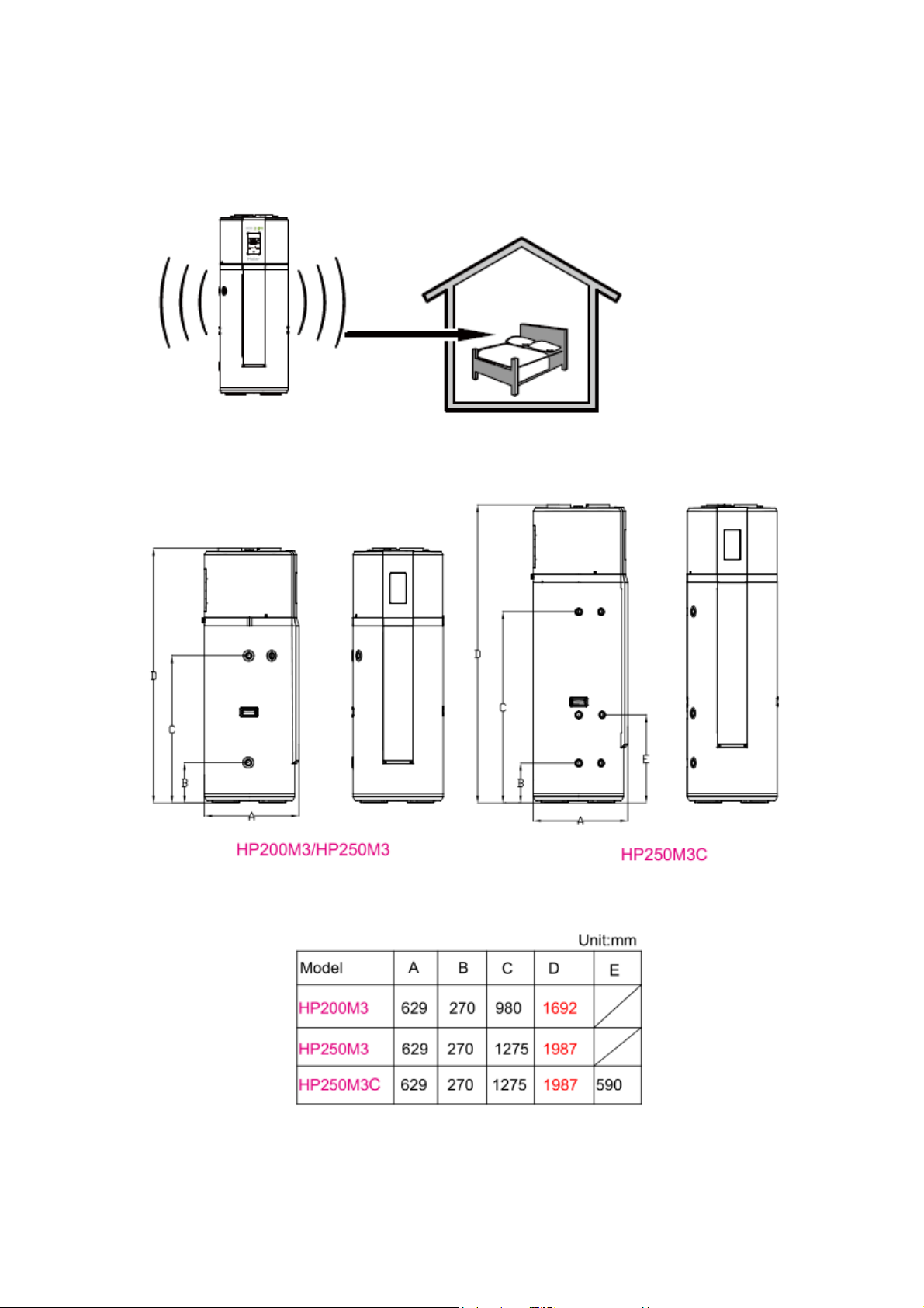
HP200M3
HP250M3
HP250M3C
Please read this manual carefully prior to your use of this water heater.
The appearance of the water heater given in this manual is for reference only.

Contents
1. Product safety statement.......................................................................................................... 3
2. Functionings & principles .................................................................................................... 4
3. Technical parameters ............................................................................................................ 5
4. Description of parts and components ................................................................................. 6
5. Installation introduction ........................................................................................................11
6. Operating and settings.............................................................................................................. 22
7. Faults and protection ............................................................................................................... 25
8. Faults and protection .................................................................................................................26
9. The method of dismantling products ........................................................................................33
10. Repairs common tools ............................................................................................................38
2

1. Product safety statement
1. This appliance can be used by children aged from 8 years and above and persons with reduced
physical, sensory or mental capabilities or lack of experience and knowledge if they have been
given supervision or instruction concerning use of the appliance in a safe way and understand the
hazards involved. Children shall not play with the appliance. Cleaning and user maintenance shall
not be made by children without supervision.
2. Children shall be closely supervised to make sure they stay away from this product.
3. The method of installing safety valve please refer to Page 16.
4. The water may drip from the discharge pipe of the pressure relief device and this pipe must be
left open to the atmosphere.
5. The water heater is to be drained according to the instructions specified on page 27.
Safety instructions (to be followed at any time)
Refrigerant: R134a; When handling product, you should
- No smoking
- Prevent the accumulation of electrostatic charges
- Work in a well ventilated place.
- Avoid contact with the skin and eyes
- Do not inhale the vapours
- Evacuate the hazardous area
- Stop the leakage
3
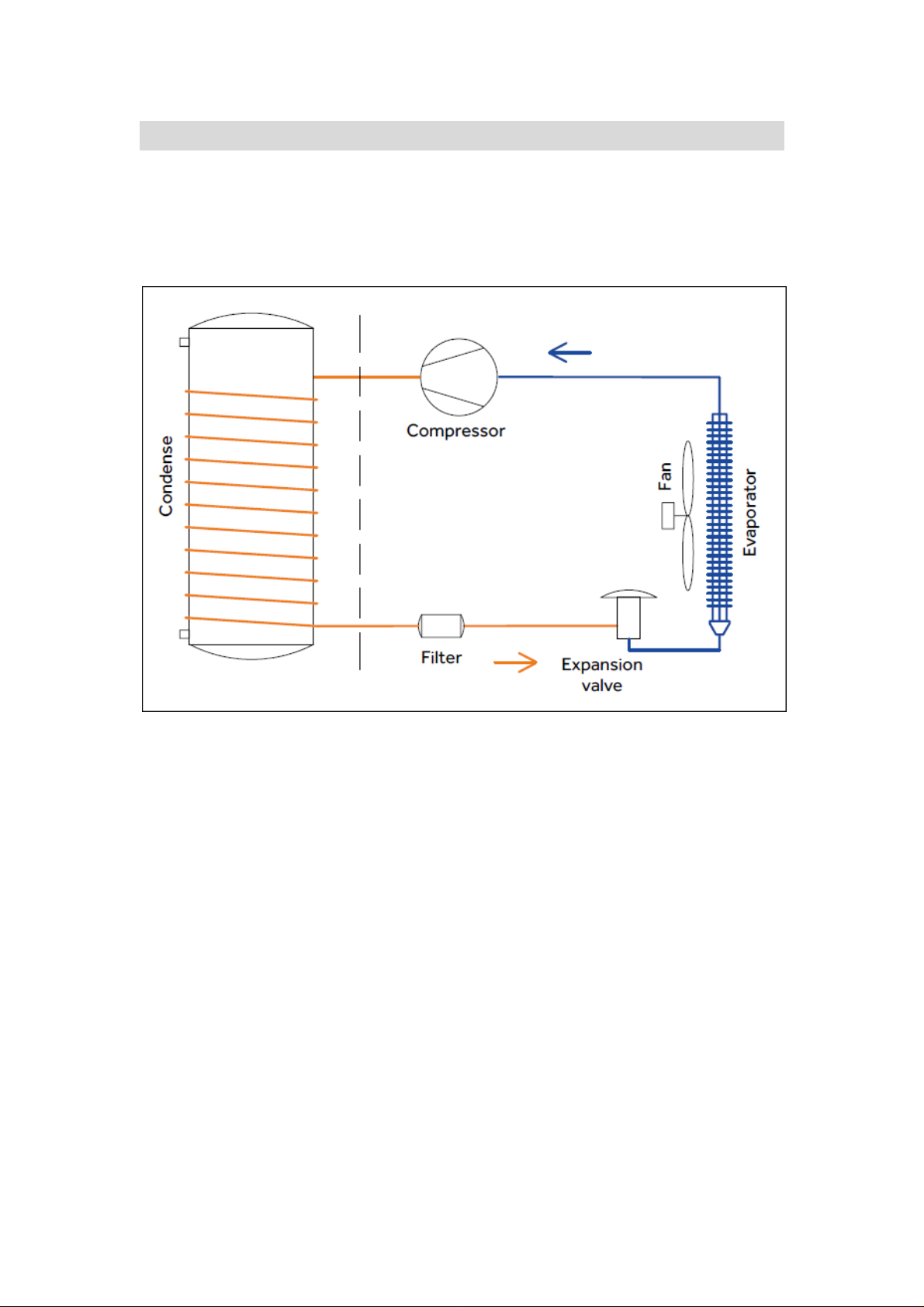
2. Functionings & principles
A low-pressure liquid refrigerant is vaporized in the heat pump's evaporator and passed into the
compressor. As the pressure of the refrigerant increases, so does its temperature. The heated
refrigerant runs through a condenser coil within the storage tank, transferring heat to the water
stored there. As the refrigerant delivers its heat to the water, it cools and condenses, and then
passes through an expansion valve where the pressure is reduced and the cycle starts over.
4
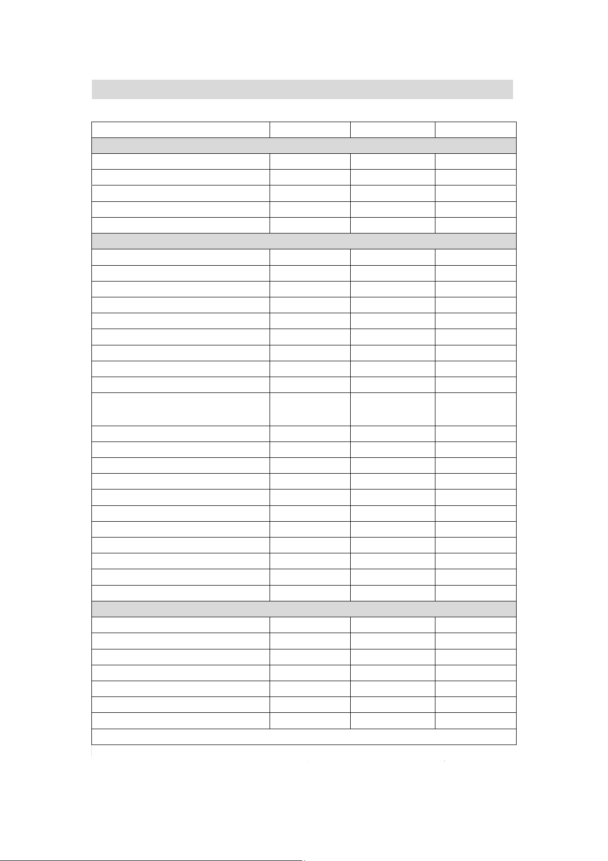
3. Technical parameters
Model HP200M3
HP250M3
HP250M3C
Tank
Tank volume 195L
246L
240L
Rated voltage/ frequency
220V~240V/50Hz
220V~240V/50Hz
220V~240V/50Hz
Tank rated pressure
0.7MPa
0.7MPa
0.7MPa
Corrosion protection
Magnesium rod
Magnesium rod
Magnesium rod
Water proof grade
IPX4 IPX4
IPX4
Performances
Type of extraction
Ambient / Exterior
Ambient / Exterior
Ambient / Exterior
COP@7℃/EN16147
3.04
3.02
3.10
COP@14℃/EN16147
3.39 3.41 3.56
Tapping cycle L L L
Power input by electric backup
1500W
1500W
1500W
Rated power input by heat pump
495W
495W
495W
Maximum power input by heat pump
865W
865W
865W
Maximum power input
2365W
2365W
2365W
Standby power input/ Pes
27W 27W
27W
Max volume of usable hot water at 40℃
setting at 55℃
224L
311L 332L
Heating up time (7℃)
5.5 h 7.35h
6.92h
Heating up time (14℃)
4.68h
6.17h
6h
Default temperature setting
55℃
55℃
55℃
Temperature setting range- with heater
35℃-75℃
35℃-75℃
35℃-75℃
Maximum length of air inlet duct
2.5m 2.5m 2.5m
Maximum length of air outlet duct
2.5m 2.5m 2.5m
Max working pressure of refrigerant
0.8/2.8MPa
0.8/2.8MPa
0.8/2.8MPa
Refrigerant type / weight
R134a/0.9kg
R134a/0.9kg
R134a/0.9kg
Sound power level
57dB 58dB
59dB
Ambient temperature for use of product
-7~35℃
-7~35℃
-7~35℃
Operating temperature of heat pump
-7~35℃
-7~35℃
-7~35℃
Dimension and connections
Water inlet and outlet connection
G3/4"F
G3/4"F
G3/4"F
Safety valve connection
G3/4"F
G3/4"F
G3/4"F
Drain & Water intlet connection
G3/4"F
G3/4"F
G3/4"F
Product Dimensions
600*629*1692mm
600*629*1987 mm
600*629*1987 mm
Packing dimension without pallet
736*695*1810 mm
736*695*2120 mm
736*695*2120 mm
Packing dimension with pallet
736*695*1940 mm
736*695*2250 mm
736*695*2250 mm
Net/Gross weight
91/103kg
102/115kg
119/132kg
* The COP and noise level data was tested in Haier lab
5
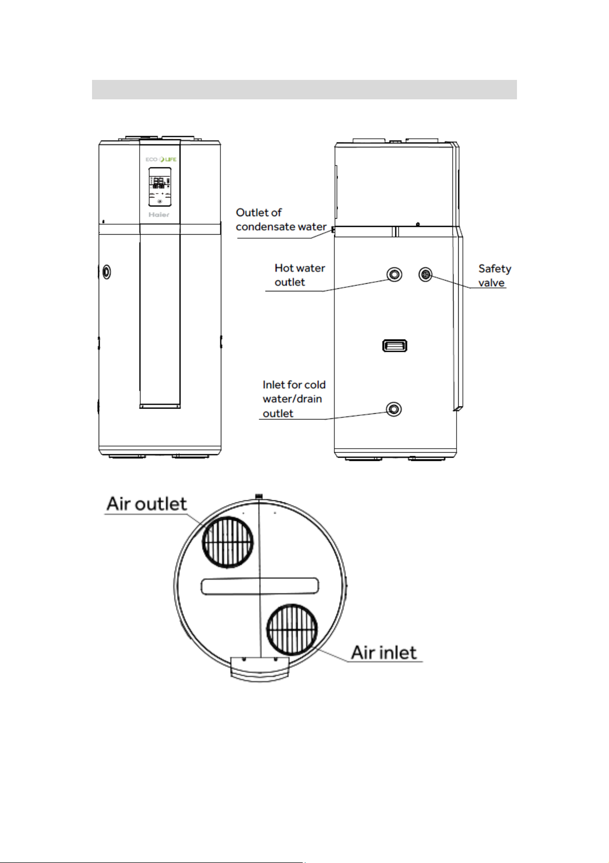
4. Description of parts and components
Heat pump structure(HP200M3/HP250M3)
6
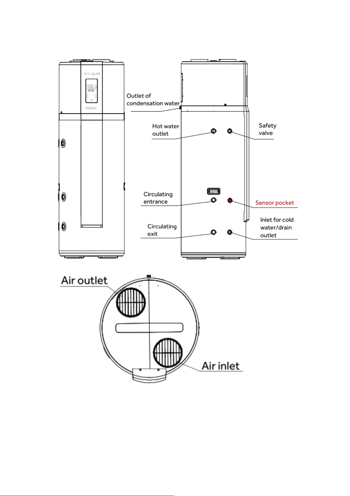
Heat pump structure(HP250M3C)
7
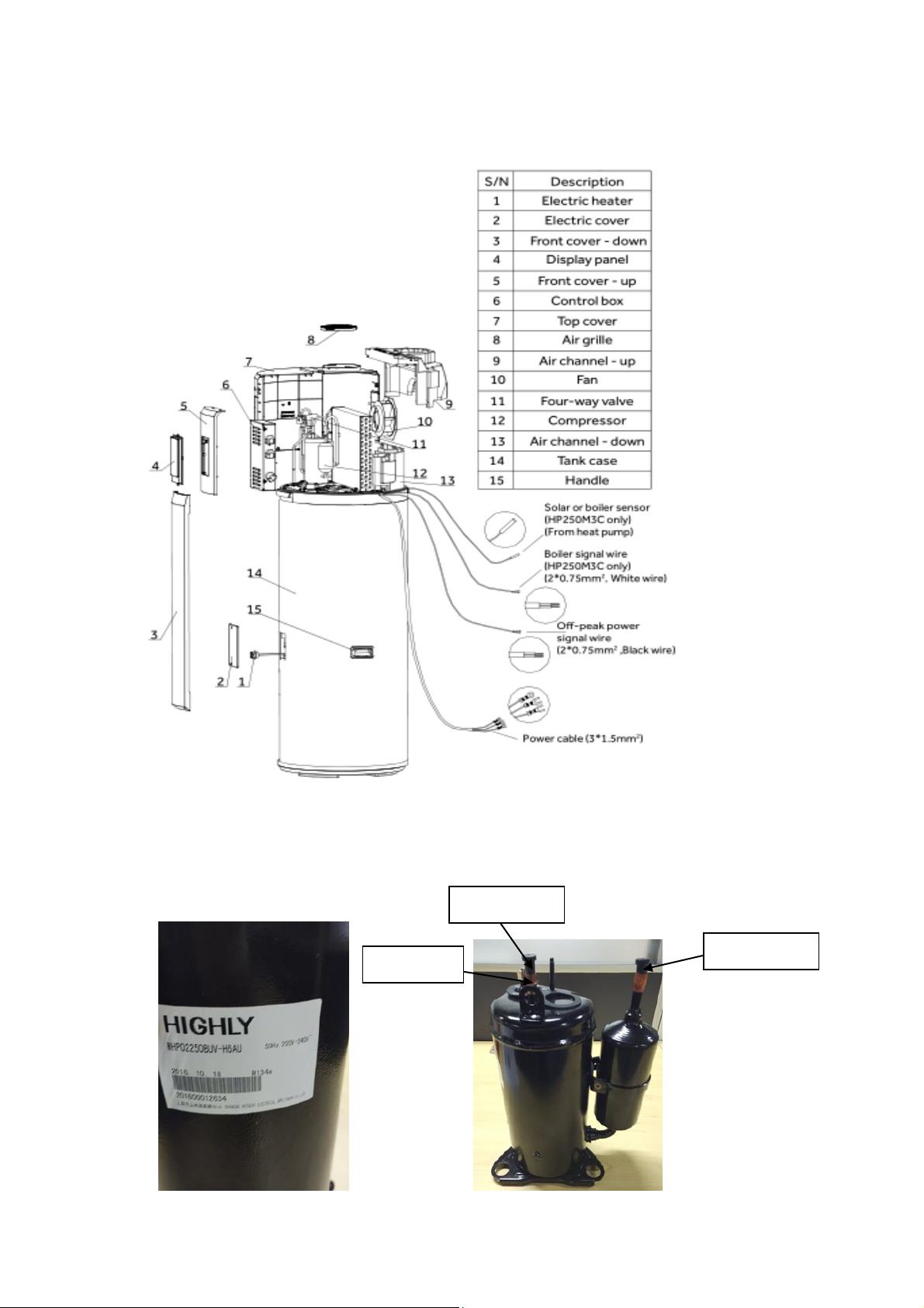
Exploded view
Intake pipe
Exhaust pipe
Wiring box
Heat pump system components
1. Compressor
The compressor is to effect a low-temperature low-pressure evaporator refrigerant vapor sucked
and compressed into high temperature and pressure of the superheated vapor, and then discharged
to the condenser heat exchanger.
8
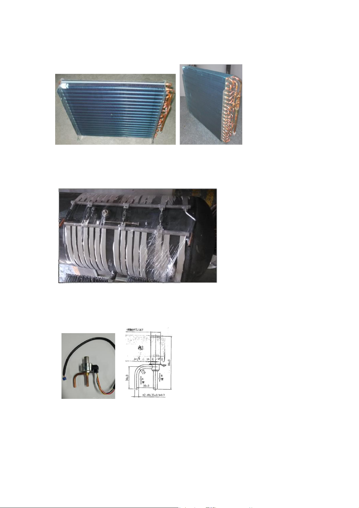
2. Evaporator
Evaporator effects: it makes the liquid refrigerant absorbs heat and is evaporated into steam.
3. Condenser
A condenser: high-temperature high-pressure refrigerant vapor is condensed into liquid, during
condensation, the refrigerant vapor discharge heat, the heat is absorbed by the heating medium.
4. Electronic expansion valve:
The refrigerant passes through the electric expansion valve, the pressure from the condensing
pressure is reduced to the evaporation pressure, part of the refrigerant will evaporate into gas in
the throttling process.
5. Filter
It’s interior has a filter and desiccant, the desiccant absorbs moisture from the refrigerant, the filter
can filter out impurities in the refrigerant.
9
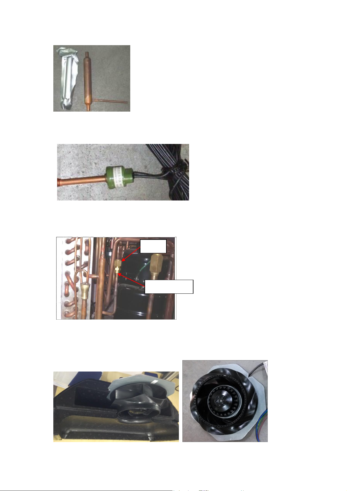
Service valve
nuts
6. High Voltage Switchgear
High-voltage switch is to prevent excessive pressure in the system, thus affecting the life of the
system components, high-pressure of the high-voltage switch is 2.8MPa.
7. Service valve
Service valve is mainly used for filling refrigerant, after removing the nuts, it contains a valve
needle, sales staff can vacuum infusion refrigerant from here.
8. Fan
It forced air through the duct, and then flows through a heat exchanger to improve heat transfer
efficiency of the heat exchanger.
10

9. Refrigerant
Heat pump refrigerant is R134a, ODP value is 0, no damage to the ozone layer. R134a refrigerant
cans appearance is as follows:
5. Installation introduction
a. Installation precaution
- Do not install the water heater in the position where exposed to gas, vapours or dust.
- Install the appliance on a flat, solid surface. The surface can support the machine weight and the
condensate water can be drained freely.
- Noise due to operating and air flow do not bother neighbors.
- Make sure there is sufficient space left for installation and maintenance.
- There is no strong electromagnetic interference around that may affect control functions.
- There is no sulfur gas or mineral oil existing at the installation place, which may cause corrosion
of the machine and the fittings.
- The water pipe for the water heater used at temperatures below 0°C shall not freeze.
- It shall not be set in rooms where a heating system is used so that heating supply to the room
will not be affected.
- It shall not be set inside a totally-enclosed space.
- The air taken in must in no event be dusty.
- Install the appliance in a dry, frost-free room.
- Temperature of the ambient air or of the air taken in by the heat pump for optimum running:
11
from 10 to 35°C.
Keep an adequate distance between the working heat-pump and the resting places.
b. Installation dimensions (mm)
12
 Loading...