

Haier HP200M2, HP250M2, HP250CM2 Installation And Service Manual
Heat Pump Water Heater
Installation and Service Manual
Model
HP200M2
HP250M2
HP250CM2
Please read this manual carefully prior to your use of this water heater.
The appearance of the water heater given in this manual is for reference only.

2
Contents
1. Product safety statement.......................................................................................................... 3
2. Functionings & principles .................................................................................................... 4
3. Technical parameters ............................................................................................................ 5
4. Description of parts and components ................................................................................. 6
5. Installation introduction ........................................................................................................11
6. Operating and settings.............................................................................................................. 22
7. Faults and protection .................................................. ................................................ ............. 25
8. Faults and protection .................................................. ................................................ ...............26
9. The method of dismantling products ........................................................................................33
10. Repairs common tools ............................................................................................................38

3
1. Product safety statement
1. This appliance can be used by children aged from 8 years and above and persons with reduced
physical, sensory or mental capabilities or lack of experience and knowledge if they have been
given supervision or instruction concerning use of the appliance in a safe way and understand the
hazards involved. Children shall not play with the appliance. Cleaning and user maintenance shall
not be made by children without supervision.
2. Children shall be closely supervised to make sure they stay away from this product.
3. The method of installing safety valve please refer to Page 16.
4. The water may drip from the discharge pipe of the pressure relief device and this pipe must be
left open to the atmosphere.
5. The water heater is to be drained according to the instructions specifi ed on pa ge 27 .
Safety instructions (to be followed at any time)
Refrigerant: R134a; When handling product, you should
- No smoking
- Prevent the accumulation of electrostatic charges
- Work in a well ventilated place.
- Avoid contact with the skin and eyes
- Do not inhale the vapours
- Evacuate the hazardous area
- Stop the leakage
4
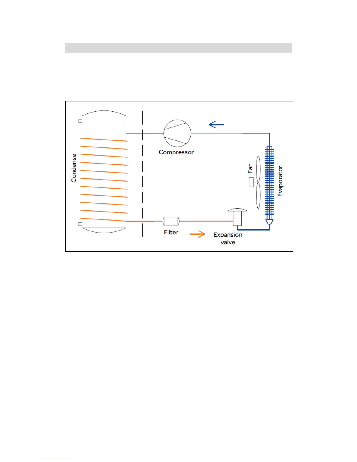
2. Functionings & principles
A low-pressure liquid refrigerant is vaporized in the heat pump's evaporator and passed into the
compressor. As the pressure of the refrigerant increases, so does its temperature. The heated
refrigerant runs through a condenser coil within the storage tank, transferring heat to the water
stored there. As the refrigerant delivers its heat to the water, it cools and condenses, and then
passes through an expansion valve where the pressure is reduced and the cycle starts over.
5
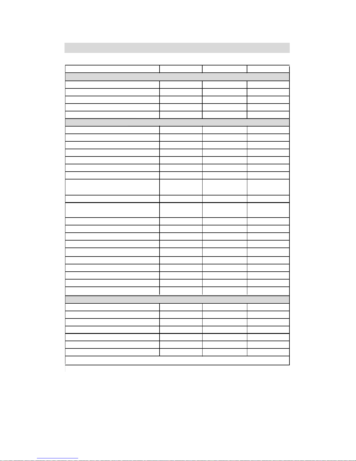
3. Technical parameters
Model HP200M2 HP250M2 HP250CM2
Tank volume 200L 250L 245L
Rated voltage/ frequency 230V/50Hz 230V/50Hz 230V/50Hz
Tank rated pressure 0.85MPa 0.85MPa 0.85MPa
Corrosion protection Magnesium rod Magnesium rod Magnesium rod
Water proof grade IPX4 IPX4 IPX4
Type of extraction Ambient / Exterior Ambient / Exterior Ambient / Exterior
COP@7
℃
/ EN16147 2.5
2.5
2.5
COP@15
℃
/ EN16147 2.9 2.9 2.9
Tapping cycle L L L
Electric heater power 2150W 2150W 2150W
Average
input - heat pump only 665W 665W 665W
Maximum input- heat pump only 850W 850W 850W
Maximum total power input of the
appliance
3000W 3000W 3000W
Standby power input/ Pes 33W 33W 33W
Max volume of usable hot water at 40
℃
setting at 55
℃
230L 300L 275L
Heating up time (7
℃
) 6.5h 8.5h 8.2h
Heating up time (15
℃
) 5.0h 6.8h 6.7h
Default temperature setting 55
℃
55
℃
55
℃
Temperature setting range- with heater 35℃-75
℃
35℃-75
℃
35℃-75
℃
Pressure drop in air circuit 25Pa 25Pa 25Pa
Max working pressure of refrigerant 0.8/2
.8MPa 0.8/2.8MPa 0.8/2.8MPa
Refrigerant type / weight R134a/0.9kg R134a/0.9kg R134a/0.9kg
Noise pressure level (2m) 40dB 40dB 40dB
Ambient temperature for use of product -5~35
℃
-5~35
℃
-5~35
℃
Operating temperature of heat pump -5~35
℃
-5~35
℃
-5~35
℃
Water inlet and outlet connection G3/4"F G3/4"F G3/4"F
Safety valve connection G3/4"F G3/4"F G3/4"F
Drain & Water intlet connection G3/4"F G3/4"F G3/4"F
Product Dimensions
600*629*1692mm 600*629*1987 mm 600*629*1987 mm
Packing dimension without pallet
736*695*1810 mm 736*695*2120 mm 736*695*2120 mm
Packing dimension with pallet
736*695*1940 mm 736*695*2250 mm 736*695*2250 mm
Net/Gross weight 104/118kg 117/131kg 136/150kg
* The COP and noise level data was tested in Haier lab
Tank
Performances
Dimension and connections
6
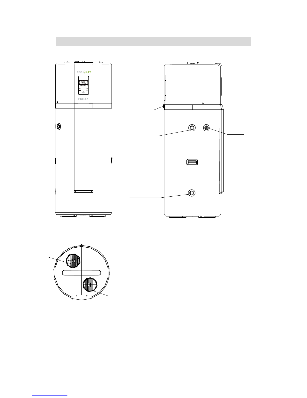
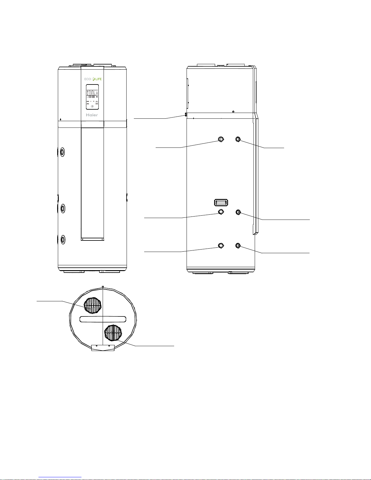
4. Description of parts and components
Heat pump structure(HP200M2/HP250M2)
Safety
valve
Outlet of
condensation water
Air inlet
Inlet for cold
water/drain
outlet
Hot water
outlet
Air outlet
7
Heat pump structure(HP250CM2)
Safety
valve
Outlet of
condensation water
Air inlet
Inlet for cold
water/drain
outlet
Hot water
outlet
Air outlet
HP250CM2
Circulating
entrance
Circulating
exit
Sensor pocket

8
Exploded view
Heat pump system components
1. Compressor
The compressor is to effect a low-temperature low-pressure evaporator refrigerant vapor sucked
and compressed into high temperature and pressure of the superheated vapor, and then discharged
to the condenser heat exchanger.
Inspiratory pipe
Exhaust pipe
Wiring box
5
6
7
9
10
13
12
11
12
3
4
1
4
15
8
Boiler signal wire
(HP250CM2 only)
(2*0.75mm2,White wire)
Power cable (3*1.5mm2)
Off-peak power
signal wire
(2*0.75mm2 ,Black wire)
Solar or boiler sensor
(HP250CM2 only)
(From heat pump)
1 Electric heater
2 Electric cover
3 Front cover - down
4 Display panel
5 Front cover - up
6 Control box
7
Compressor
8 Air grille
9 Air channel - up
Air channel - down
10 Fan
11 Four-way valve
12
Top cover
Tank case
13
14
15 Handle
S/N Description
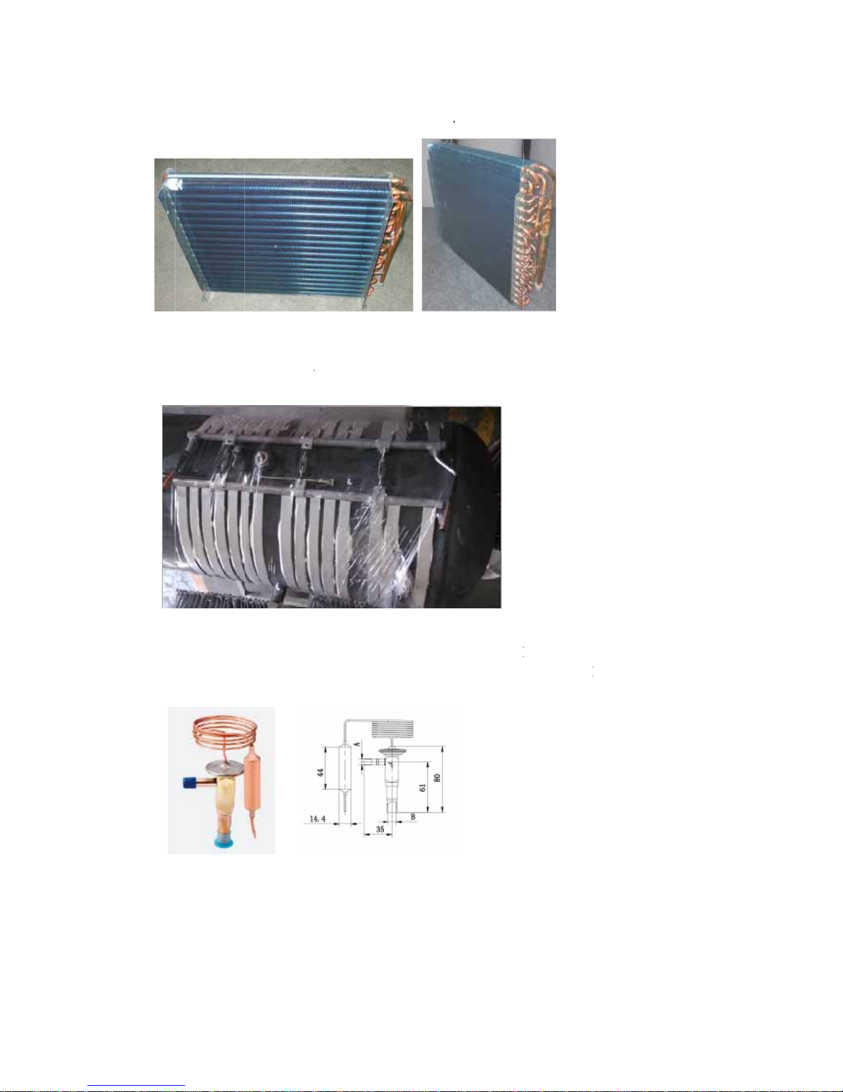
2. E
v
Eva
p
3. C
A c
o
con
d
4. T
h
The
pres
the
t
5. F
i
It’s
i
can
v
aporator
orator effec
t
ondenser
ndenser: hi
g
ensation, th
e
ermal expa
n
refrigerant
p
sure is redu
c
hrottling pro
lter
nterior has a
filter out im
p
s: it makes t
h
h-temperat
u
refrigerant
v
sion valve:
asses throu
g
ed to the ev
a
cess.
filter and de
urities in the
e liquid refr
i
re high-pres
s
apor discha
r
h the ther
m
poration pr
e
siccant, the
d
refrigerant.
9
gerant abso
r
ure refriger
a
ge heat, the
h
al expansio
n
ssure, part
o
esiccant abs
o
bs heat and i
s
nt vapor is
eat is absor
b
valve, the
p
f the refrige
r
rbs moistur
e
evaporated
condensed i
n
ed by the he
a
p
ressure fro
m
ant will eva
p
from the re
f
into steam.
to liquid, d
u
ting mediu
m
the conde
n
p
orate into
g
rigerant, the
ring
.
sing
as in
filte
r
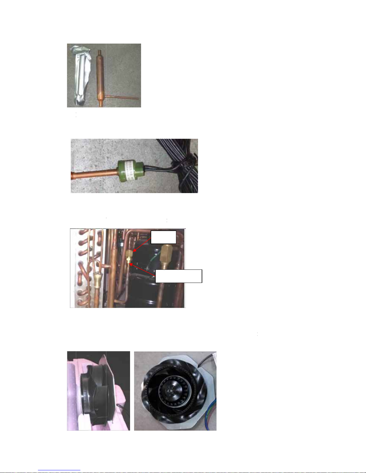
6.
H
Hig
h
syst
e
7. S
e
Ser
v
nee
d
8. F
a
It f
o
effi
c
igh Voltage
S
-voltage sw
i
m compone
n
rvice valve
ice valve is
le, sales sta
ff
n
rced air thr
o
iency of the
witchgear
tch is to pr
e
ts, high-pre
s
mainly use
d
can vacuu
m
ugh the duc
t
heat exchan
g
vent excessi
v
sure of the
h
for filling
r
infusion re
fr
, and then f
l
er.
Se
r
nuts
10
e pressure
i
igh-voltage
s
efrigerant, a
f
igerant fro
m
ows through
vice valve
n the syste
m
witch is 2.8
M
ter removin
g
here.
a heat exch
a
, thus affect
i
Pa.
the nuts, i
t
nger to imp
r
ng the life
o
contains a
v
r
ove heat tr
a
f the
alve
nsfer
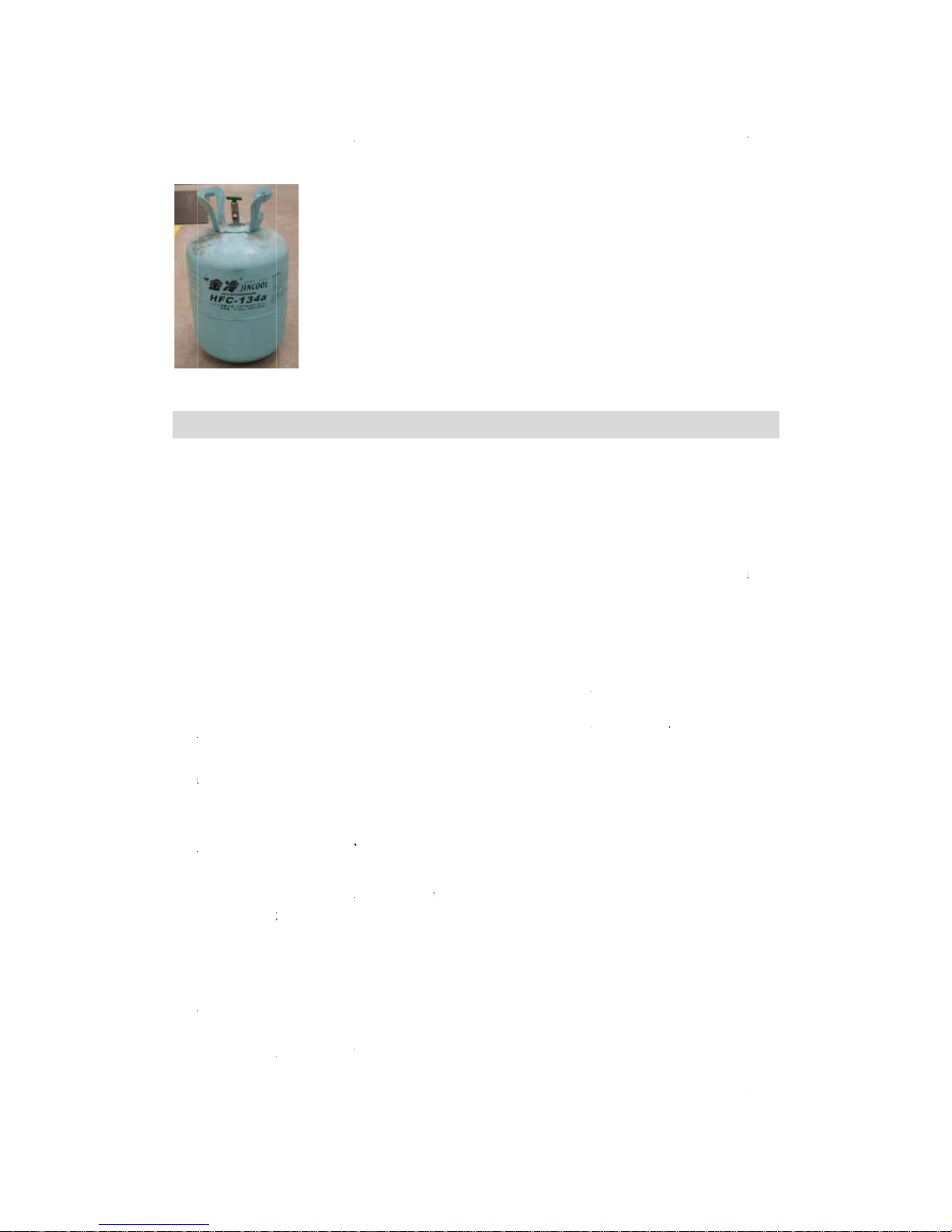
9.
R
Hea
t
can
s
5.
I
a. I
- D
o
- In
s
con
d
- N
o
- M
a
- T
h
- T
h
of t
h
- T
h
- I
will
- It
s
- T
h
- In
s
- Te
efrigerant
pump refri
g
appearance
nstalla
t
nstallatio
n
not install t
h
tall the appl
i
ensate wate
r
ise due to o
p
ke sure ther
e
ere is no stro
ere is no sul
f
e machine a
n
e water pipe
t shall not b
e
not be affec
t
hall not be s
e
e air taken i
n
tall the appl
i
mperature o
f
erant is R13
4
is as follows
:
ion intr
o
precauti
e water heat
ance on a fl
a
can be drai
n
erating and
a
is sufficien
t
ng electrom
a
ur gas or mi
n
d the fitting
s
for the wate
r
set in roo
m
ed.
t inside a to
t
must in no
e
ance in a dr
y
the ambien
t
a, ODP val
u
ductio
n
on
er in the pos
i
t, solid surf
a
ed freely.
ir flow do n
o
space left f
o
gnetic interf
e
eral oil exis
t
.
heater used
a
s where a h
e
ally-enclose
d
vent be dust
y
, frost-free r
o
air or of t
h
11
e is 0, no d
a
tion where e
x
ce. The surf
a
t bother nei
g
r installation
rence aroun
d
ing at the in
s
t temperatu
r
ating syste
m
space.
.
om.
e air taken i
mage to the
posed to ga
s
ce can supp
o
hbors.
and mainte
n
that may a
ff
tallation pla
c
es below 0°
C
is used so t
h
n by the he
a
ozone layer.
, vapours or
rt the machi
ance.
ect control
f
e, which m
a
shall not fr
e
at heating s
u
t pump for
o
R134a refri
g
dust.
ne weight a
n
unctions.
y cause corr
o
eze.
pply to the
r
ptimum run
n
erant
d the
sion
oom
n
ing:

12
from 10 to 35°C.
Keep an adequate distance between the working heat-pump and the resting places.
b. Installation dimensions (mm)
HP200M2/HP250M2
HP250CM2
 Loading...