

Haier HCC2230AGS Installation Manual

Installation Instructions
Instructions d’installation
Instrucciones de instalación
HCC2230AGS
HCC3230AGS
24” and 30” Gas Cooktops
Tables de cuisson à gaz de 24” et 30”
Supercies de cocción a gas de 24” y 30”
OFF
OFF
OFF
OFF
ON
ON
ON
MIN
MIN
ON
MIN
MIN
Installation Instructions
Figure 6
INSTALLATION AND SERVICE MUST BE PERFORMED BY A QUALIFIED INSTALLER.
IMPORTANT: SAVE THESE INSTRUCTIONS FOR LOCAL ELECTRICAL INSPECTOR'S USE.
READ AND SAVE THESE INSTRUCTIONS FOR FUTURE REFERENCE.
Advance Preparation
• For proper operation of a gas appliance, the air necessary for the combustion of the gas must be
able to flow into the room naturally. The air must flow into the room directly through openings in the
outside walls. These openings must have an unobstructed cross-section not less than 2m3/hfor each
kw of power (see total power in kw on the appliance).
• This opening must be constructed so that it will not be obstructed from inside or outside, or
constructed close to the floor. The opening is recommended to be on the side opposite to that on
which the flue gases are discharged.
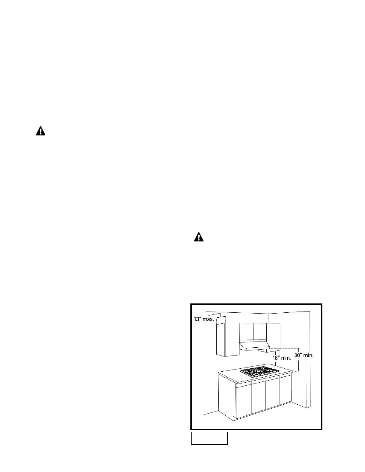
• Avoid placing cabinetry directly above
cooktop when possible. If cabinetry is used
above cooking surface, use cabinets no more
than 13″ deep (see Figure 6).
• Working areas adjacent to the cooktop
should have 18″ minimum clearance between
countertop and cabinet bottom.
Make sure the wall coverings, countertop and
cabinets around the cooktop can withstand
heat (up to 200º F) generated by the cooktop.
• Maintain 30″ minimum clearance between
cooktop surface and cabinets installed above
• If range hood is installed above cooktop,
maintain a 30” minimum clearance between
cooktop and bottom of range hood. The range
hood must be connected directly to flues or to
the outside.
the cooktop.
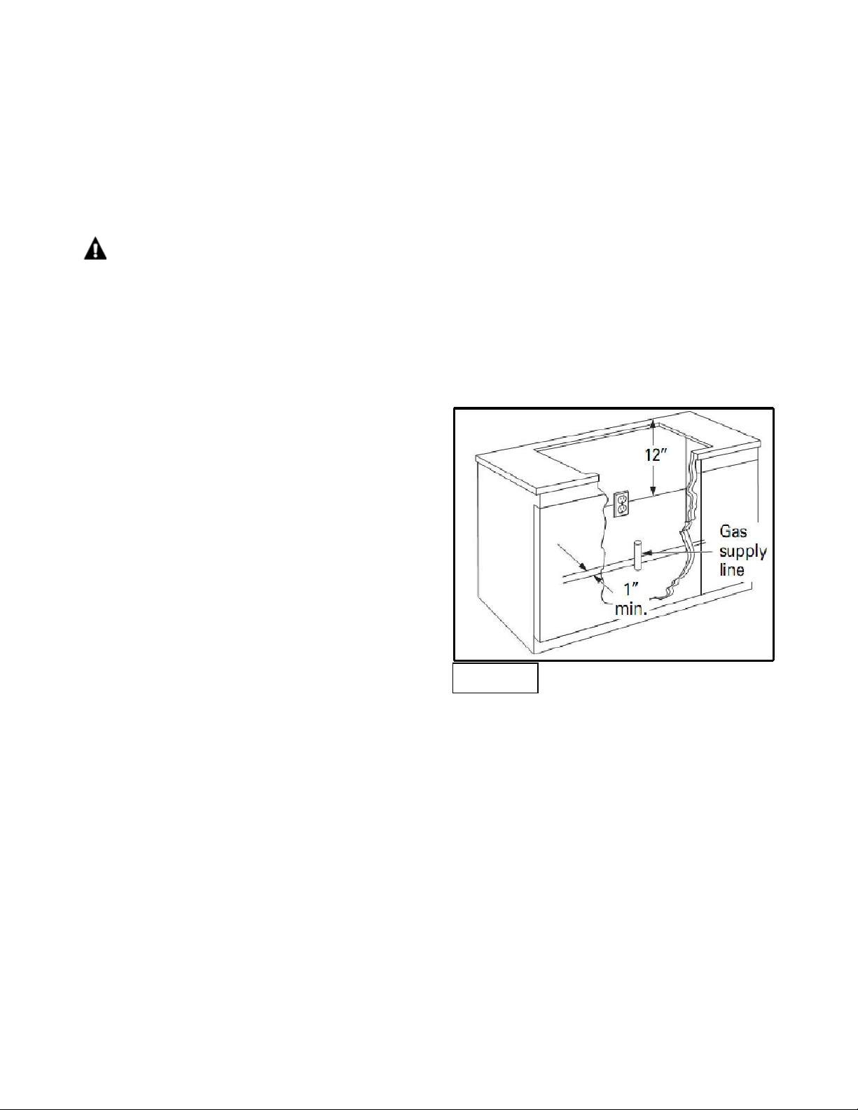
Figure 7
• A range hood with minimum 350 CFM that projects at least 5” beyond front of cabinets can reduce
risk of burns caused by reaching over heated surface units.
Provide an Adequate Gas and Electrical Supply
• Installation must comply with local codes. In the absence of local codes, the gas cooktop must
comply with the National Fuel Gas Code ANSI Z223.1—latest edition in the United States, or in
Canada CAN/CGA B149.1, and CAN/CGA B149.2, and the National Electrical Code ANSI/NFPA No.
70—latest edition in United States, or in Canada CSA Standard C22.1, Canadian Electrical Code,
Part 1, and local code requirements.
• Gas supply should be located near the
opening for this cooktop and be a minimum of
1” from the back wall (see Figure 7). This
cooktop is set for natural gas and is designed
to operate at 5” water column pressure. The
regulator is required to provide a minimum of
6” water column to a maximum of 14” water
column to the cooktop regulator.
• The electric spark ignition feature for this model requires a 120V electrical power supply and should
be located 12” below the countertop and within reach of the cooktop’s four-foot power cord.
Tools and Materials Needed
Figure 8
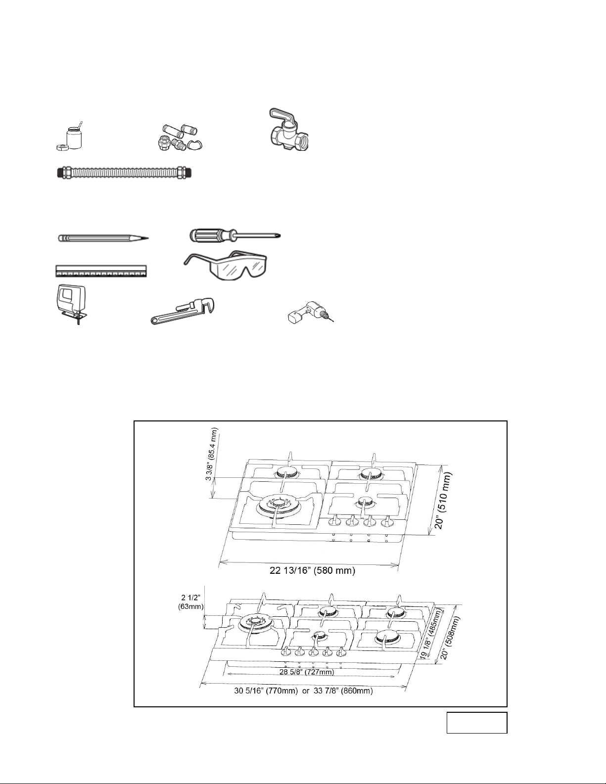
MATERIALS YOU WILL NEED:
Joint Sealant Pipe Fittings Shut-Off Valve
CSA-Approved Flexible ½” or ¾” Gas Line
TOOLS YOU WILL NEED:
Pencil Phillips-Head Screwdriver
Ruler Safety Glasses
Saber Saw Pipe Wrench 1/8” Drill Bit & Electric or Hand Drill
Cutting the Countertop
1) Use a 24” or deeper base cabinet.
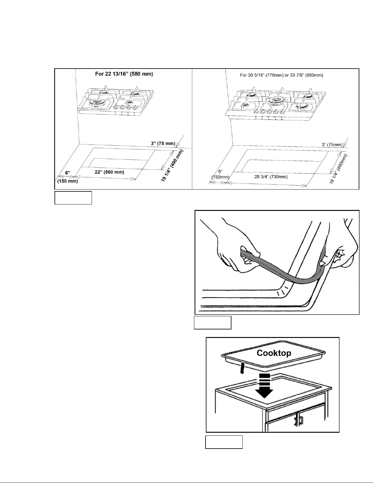
2) Cut the opening in the countertop. To ensure accuracy it is best to make a template (see Figure 9) for
Figure 9
Figure 10
Figure 11
the opening. Make sure the sides are parallel also rear and front cuts are exactly perpendicular to the
sides. Observe all minimum clearances.
3) Before inserting the cooktop into the
opening in the countertop, remove the
grates and burner caps, turn the
cooktop upside down and place the
special foam gasket around the bottom
edge of the cooktop (see Figure 10). It
is important to fix this gasket evenly,
without gaps or overlapping, to prevent
liquid seeping underneath the cooktop.
4) After the foam gasket has been affixed,
place the cooktop into the countertop
(see Figure 11).
 Loading...